Embed Size (px)
Citation preview
DeltaV SIS Product Data Sheet
February 2016 – Page 1 DeltaV SIS Logic Solver
www.DeltaVSIS.com
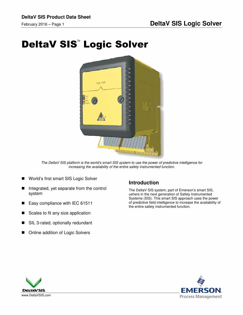
DeltaV SISTM
Logic Solver
The DeltaV SIS platform is the world’s smart SIS system to use the power of predictive intelligence for increasing the availability of the entire safety instrumented function.
World’s first smart SIS Logic Solver
Integrated, yet separate from the control system
Easy compliance with IEC 61511
Scales to fit any size application
SIL 3-rated, optionally redundant
Online addition of Logic Solvers
Introduction
The DeltaV SIS system, part of Emerson’s smart SIS, ushers in the next generation of Safety Instrumented Systems (SIS). This smart SIS approach uses the power of predictive field intelligence to increase the availability of the entire safety instrumented function.

DeltaV SIS Product Data Sheet
February 2016 – Page 2 DeltaV SIS Logic Solver
Benefits
The World’s first smart SIS. Research shows that over 85% of all faults in SIS applications occur in field instruments and final control elements. The DeltaV SIS system has the first smart Logic Solver. It communicates with intelligent field devices using the HART protocol to diagnose faults before they cause spurious trips. This approach increases process availability and reduces lifecycle costs.
Integrated yet separate. Safety standards insist on separation of the control and safety systems in order to remove any possibility of a common failure affecting both layers of protection. End users require an integrated configuration, maintenance, and operations environment. The DeltaV SIS system has a unique solution to this problem; implementing safety functions with dedicated hardware, software, and networks while being seamlessly integrated at the workstations.
Easy Compliance with IEC 61511. IEC 61511 demands rigorous user management and the DeltaV SIS platform provides it. IEC 61511 requires that any changes made from an HMI (e.g. to a trip limit) be extensively vetted to ensure that the right data is written to the right Logic Solver. The DeltaV SIS system automatically provides this data verification.
Scales to fit any size application. Whether you have an isolated wellhead or a large ESD/fire and gas application, the DeltaV SIS system scales to provide you with the safety coverage you need for your SIL 1, 2 and 3 safety functions. Each Logic Solver has dual CPUs and sixteen channels of I/O built into it. This means that no additional processors will ever be required to expand the system, since each Logic Solver contains its own CPUs. Scan rate and memory usage are constant and independent of system size.
The DeltaV SIS system scales to fit your safety application.
SIL 3-rated, optionally redundant. DeltaV SLS 1508 Logic Solvers can be installed in redundant pairs for increased process availability of your SIS loops.
A redundant pair of SLS 1508 Logic Solvers
Redundant architecture includes:
dedicated redundancy link
separate power supply to each Logic Solver
I/O published locally every scan on redundant peer-to-peer link
same input data for each Logic Solver
Online addition of Logic Solvers. The system checks for new hardware every scan, so equipment can be added to an on-line system in real time. Online addition of new modules means your process does not get interrupted. As new equipment is added, the DeltaV Explorer software recognizes it and makes it ready to be configured.
DeltaV SIS Product Data Sheet
February 2016 – Page 3 DeltaV SIS Logic Solver
Product Description
This section provides general information on DeltaV SIS hardware. Refer to the Installing Your DeltaV Digital Automation System manual for more information on DeltaV system equipment.
DeltaV SIS Equipment
A DeltaV automation system consists of carriers, one or more I/O subsystems, controllers, power supplies, workstations, and a control network.
The DeltaV SIS system consists of:
Logic Solvers (SLS 1508) and termination blocks
SISnet Repeaters (see separate product data sheet)
Carrier extender cables
Local peer bus extender cables
Right 1-wide carrier with termination
Logic Solvers (SLS) contain the logic-solving capability and provide an interface to 16 I/O channels that can be configured as Discrete Input, Discrete Output, Analog Input (HART) and HART two-state output channels. Logic Solvers and termination blocks install on the 8-wide carrier. The DeltaV SIS platform supports simplex and redundant Logic Solvers. Logic Solvers communicate with each other through the carriers over a two-channel, local peer bus (SISnet) and remote peer ring. Local Logic Solvers are hosted by the same DeltaV controller and remote Logic Solvers are hosted by a different DeltaV controller. Logic Solvers are powered by a 24 V DC power supply that is separate from the power supply that drives the DeltaV controller and I/O. Logic Solvers install in odd-numbered slots (1,3,5,7) on the 8-wide carrier. Simplex Logic Solvers use two slots and redundant Logic Solvers use four slots.
SISnet Repeaters extend communication beyond the local Logic Solvers connected to one DeltaV controller and broadcast global messages to remote Logic Solvers through a fiber-optic ring Carrier extender cables extend Local Bus power and signals between 8-wide carriers. Local peer bus extender cables extend the local peer bus (SISnet) between Logic Solvers on different carriers. 1-wide carriers with terminators terminate the local peer bus at the final carrier.
Communication
Control Network: The DeltaV Control Network provides communication between the nodes in the DeltaV network. Refer to the Installing Your DeltaV Digital Automation System manual for complete information on the Control Network.
Local Bus: The Local Bus provides communication between DeltaV controllers and Logic Solvers and between DeltaV controllers and SISnet Repeaters.
Local Peer Bus (SISnet): Logic Solvers communicate with other Logic Solvers and with local SISnet Repeaters through the carriers over a 2 channel local peer bus. The same message is broadcast over both channels. The local peer bus must be terminated at both ends. The local peer bus is terminated at the left end through the 2-wide power/controller carrier and at the right end through a terminated 1-wide carrier.
The SISnet Repeaters can be located anywhere on a local peer bus – between the MQ Controller(s) and the terminated 1-wide carrier.
Remote Peer Ring: SISnet Repeaters hosted by one DeltaV controller communicate with SISnet Repeaters hosted by a different DeltaV controller over a fiber-optic remote peer ring. A local SISnet Repeater collects locally generated messages that have been designated as global variables into a single message and sends it to the next SISnet Repeater in the ring. Upon receipt of a message, the receiving SISnet Repeater broadcasts it on its local peer bus (SISnet) and forwards the message to the next SISnet Repeater in the ring. A global message is forwarded around the ring once. The primary SISnet Repeaters form one fiber-optic ring and the secondary form a separate, independent ring.
Carrier extender cables and local peer bus extender cables connecting a DeltaV controller and 8-wide carrier with standard DeltaV I/O and DeltaV SIS to a second 8-wide carrier (hosted by the same controller) are installed with Logic Solvers, SISnet Repeaters, and a terminated 1-wide carrier. Logic Solver messages are communicated to a remote DeltaV SIS (hosted by a separate controller) through fiber-optic cables.
DeltaV SIS Product Data Sheet
February 2016 – Page 4 DeltaV SIS Logic Solver
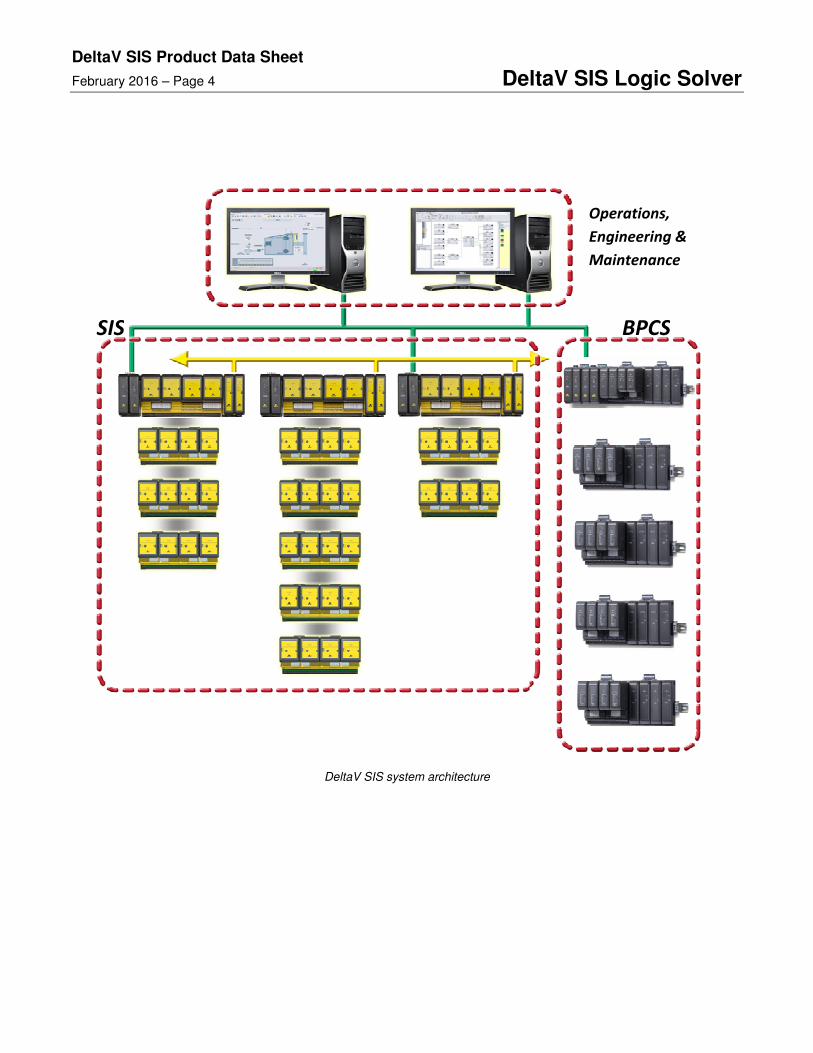
DeltaV SIS system architecture
SIS BPCS
Operations,
Engineering &
Maintenance
DeltaV SIS Product Data Sheet
February 2016 – Page 5 DeltaV SIS Logic Solver
Unique Redundancy Methodology
Introduction to Redundancy
Unlike other SIS Logic Solvers, the SLS 1508 is rated suitable for use in SIL 3 applications in simplex mode. However, some end users may wish to use redundant SLS 1508 modules to increase their process availability.
When redundant SLS 1508 modules are chosen, the two modules run in parallel at all times. Both read the inputs from the I/O terminals, both execute the logic and both drive the outputs at the I/O terminals. There is no concept of primary and backup or master and slave, which is unlike any other SIS. The only difference between the two is that one communicates with both the engineering and operator workstations and the dedicated safety network (SISnet); this is the one with the Active light on the bezel. The other (Standby) is communicating only on the SISnet.
In the event that a failure is detected in one of the SLS 1508 modules, it automatically goes to a failed state. In this condition all its output channels are de-energized; this has no impact on the other Logic Solver or the physical outputs because the other module continues to read inputs, execute logic and drive outputs. The transition from redundant to simplex mode is therefore completely bumpless.
Redundancy
The redundant SLS 1508 Logic Solver modules are connected to the field at the redundant terminal block. No control strategy configuration is required to take advantage of SLS 1508 Logic Solver redundancy, as the system’s auto-sense capability automatically recognizes the redundant pair of cards.
An integrity error alarm in a redundant Logic Solver pair will notify the operator of a failure. Both Logic Solvers in a redundant pair are monitored for integrity alarms at all times.
Events that can cause integrity alarms include:
Hardware failure within a Logic Solver
Communications failure between a Logic Solver and the SISnet
Communications failure between a redundant pair of Logic Solvers
Communications failure between a Logic Solver and an MQ Controller
Removal of a Logic Solver from the carrier
The health and status of both Logic Solvers and their channels are available in the diagnostics explorer.
When one of a redundant pair of SLS 1508 modules is removed online there is no disturbance to the process. When the missing module is replaced with another module, the new module completes its power-up self-tests before the active module cross-loads the current database. In safe areas, failed cards can be replaced under power. In hazardous areas, appropriate installation procedures must be followed.
Automatic proof testing can be selected on a redundant pair of Logic Solvers. The desired proof-test interval is set in the configuration and the Logic Solvers perform the proof test automatically. A warning is given to the operator before the automatic proof test is started.
Sequence of Events Capability
The Cause and Effects Matrix and Boolean Fan Input Function Blocks trap the first out cause per effect automatically at the scan rate of the Logic Solver, which is 50 mS by default. This first-out cause is stored in the Event Chronicle. In general, when there is a plant event that triggers an emergency shutdown from the SIS, one input will exceed a trip limit on one scan and this will cause outputs to trip and more inputs will then change state. Sequence of Events Recording has been used to find that first input that caused the trip by looking at all of the inputs in the plant. With the DeltaV SIS system, the operator simply filters the Event Chronicle for first out trips, and the first-out is clearly visible.
If higher resolution is required for some channels then they should be wired to both the DeltaV SIS Logic Solver and also to a DeltaV Discrete Input Card for Sequence of Events.
DeltaV SIS Product Data Sheet
February 2016 – Page 6 DeltaV SIS Logic Solver
System Compatibility
DeltaV SLS 1508 Specifications
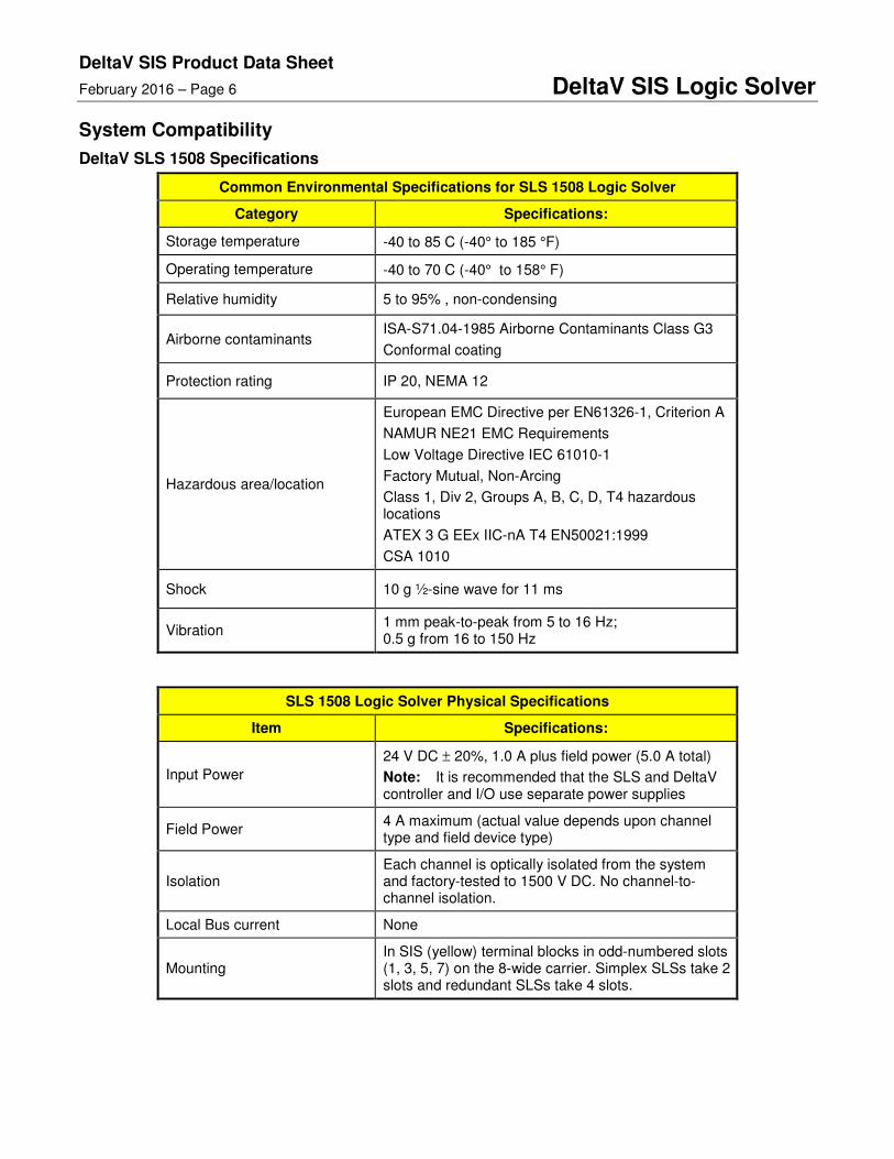
Common Environmental Specifications for SLS 1508 Logic Solver
Category Specifications:
Storage temperature -40 to 85 C (-40° to 185 °F)
Operating temperature -40 to 70 C (-40° to 158° F)
Relative humidity 5 to 95% , non-condensing
Airborne contaminants ISA-S71.04-1985 Airborne Contaminants Class G3
Conformal coating
Protection rating IP 20, NEMA 12
Hazardous area/location
European EMC Directive per EN61326-1, Criterion A
NAMUR NE21 EMC Requirements
Low Voltage Directive IEC 61010-1
Factory Mutual, Non-Arcing
Class 1, Div 2, Groups A, B, C, D, T4 hazardous locations
ATEX 3 G EEx IIC-nA T4 EN50021:1999
CSA 1010
Shock 10 g ½-sine wave for 11 ms
Vibration 1 mm peak-to-peak from 5 to 16 Hz; 0.5 g from 16 to 150 Hz
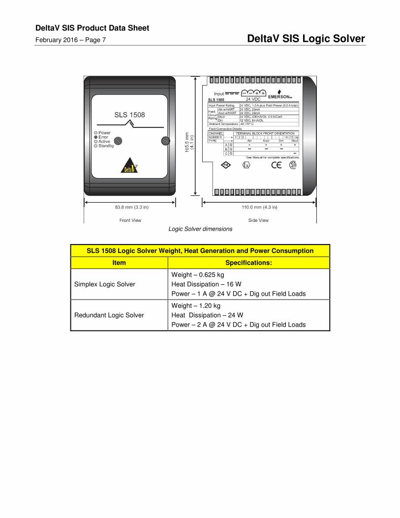
SLS 1508 Logic Solver Physical Specifications
Item Specifications:
Input Power
24 V DC ± 20%, 1.0 A plus field power (5.0 A total)
Note: It is recommended that the SLS and DeltaV controller and I/O use separate power supplies
Field Power 4 A maximum (actual value depends upon channel type and field device type)
Isolation Each channel is optically isolated from the system and factory-tested to 1500 V DC. No channel-to-channel isolation.
Local Bus current None
Mounting In SIS (yellow) terminal blocks in odd-numbered slots (1, 3, 5, 7) on the 8-wide carrier. Simplex SLSs take 2 slots and redundant SLSs take 4 slots.
DeltaV SIS Product Data Sheet
February 2016 – Page 7 DeltaV SIS Logic Solver
Logic Solver dimensions
SLS 1508 Logic Solver Weight, Heat Generation and Power Consumption
Item Specifications:
Simplex Logic Solver
Weight – 0.625 kg
Heat Dissipation – 16 W
Power – 1 A @ 24 V DC + Dig out Field Loads
Redundant Logic Solver
Weight – 1.20 kg
Heat Dissipation – 24 W
Power – 2 A @ 24 V DC + Dig out Field Loads
DeltaV SIS Product Data Sheet
February 2016 – Page 8 DeltaV SIS Logic Solver
Channel Specifications
The Logic Solver provides 16 channels of flexible I/O, meaning that each channel can be configured as an Analog Input (HART), HART Two-State Output, Discrete Input, or Discrete Output channel.
Analog Input Channel Specifications (includes HART)
Item Specifications:
Number of channels 16
Isolation Each channel is optically isolated from the system and factory-tested to 1500 V DC. No channel-to-channel isolation.
Nominal signal span 4 to 20 mA
Full signal range 1 to 24 mA
2-wire transmitter power 15.0 V minimum terminal-to-terminal @ 20 mA; current limited to 24 mA max
Safety / diagnostic accuracy 2.0% of span
Resolution 16 bits
Filtering
2-pole, corner frequency 5.68 Hz
-3 dB at 5.68 Hz
-20.0 dB at 40 Hz (half the sample rate)
Wiring diagram and terminations for HART analog input channels
DeltaV SIS Product Data Sheet
February 2016 – Page 9 DeltaV SIS Logic Solver
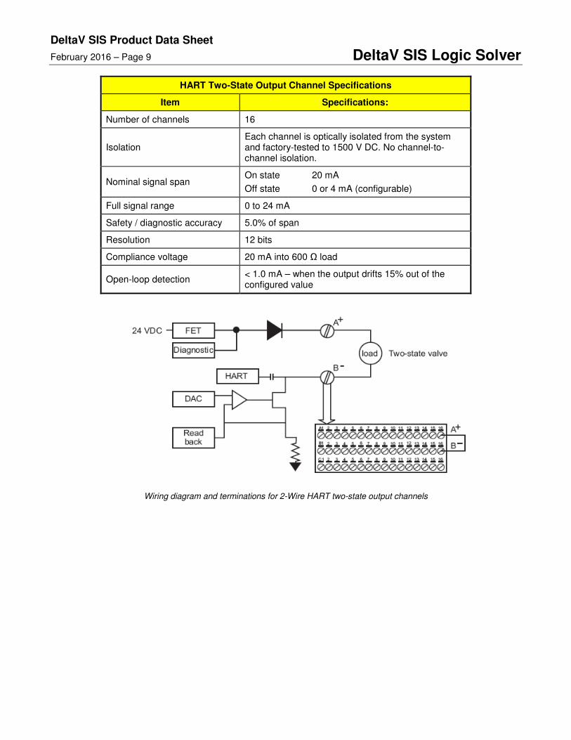
HART Two-State Output Channel Specifications
Item Specifications:
Number of channels 16
Isolation Each channel is optically isolated from the system and factory-tested to 1500 V DC. No channel-to-channel isolation.
Nominal signal span On state 20 mA
Off state 0 or 4 mA (configurable)
Full signal range 0 to 24 mA
Safety / diagnostic accuracy 5.0% of span
Resolution 12 bits
Compliance voltage 20 mA into 600 Ω load
Open-loop detection < 1.0 mA – when the output drifts 15% out of the configured value
Wiring diagram and terminations for 2-Wire HART two-state output channels
DeltaV SIS Product Data Sheet
February 2016 – Page 10 DeltaV SIS Logic Solver
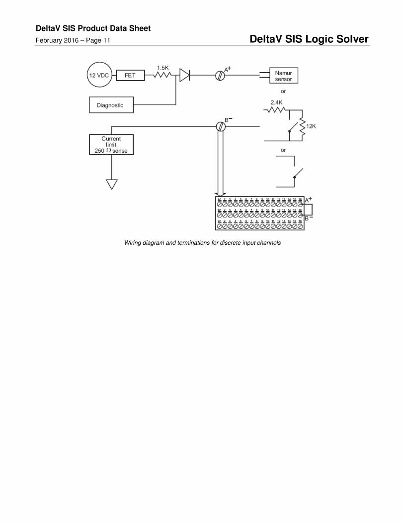
Discrete Input Channel Specifications
Item Specifications:
Number of channels 16
Isolation Each channel is optically isolated from the system and factory-tested to 1500 V DC. No channel-to-channel isolation.
Detection level for ON ≥ 2 mA
Detection level for OFF ≤ 1.65 mA
Input impedance ~ 1790 Ω
Input compatibility
Inputs compatible with:
NAMUR sensors (12 V)
Dry contact
Dry contact with end-of-line resistance
Line fault detection – short circuit (optional)
100 Ω
> 6 mA
Line fault detection – open circuit (optional)
> 40 kΩ
< 0.35 mA
Line Fault Detection — The Discrete Input channels have line fault detection for detecting open or short circuits in field wiring. To use this capability you must:
Enable line fault detection in your configuration. Enable line fault detection on a channel-by-channel basis when you configure the channels.
Connect the dry contact to external resistors. Connect the dry contact to a 12 KΩ resistor in parallel (allows the open circuit detection) and a 2.4 KΩ resistor in series (allows short circuit detection).
Line Fault Detection in NAMUR Sensors — Line fault detection is built into NAMUR sensors. Do not use external resistors with NAMUR sensors; however, you must enable line fault detection in your configuration when using NAMUR sensors.
DeltaV SIS Product Data Sheet
February 2016 – Page 11 DeltaV SIS Logic Solver
Wiring diagram and terminations for discrete input channels
DeltaV SIS Product Data Sheet
February 2016 – Page 12 DeltaV SIS Logic Solver
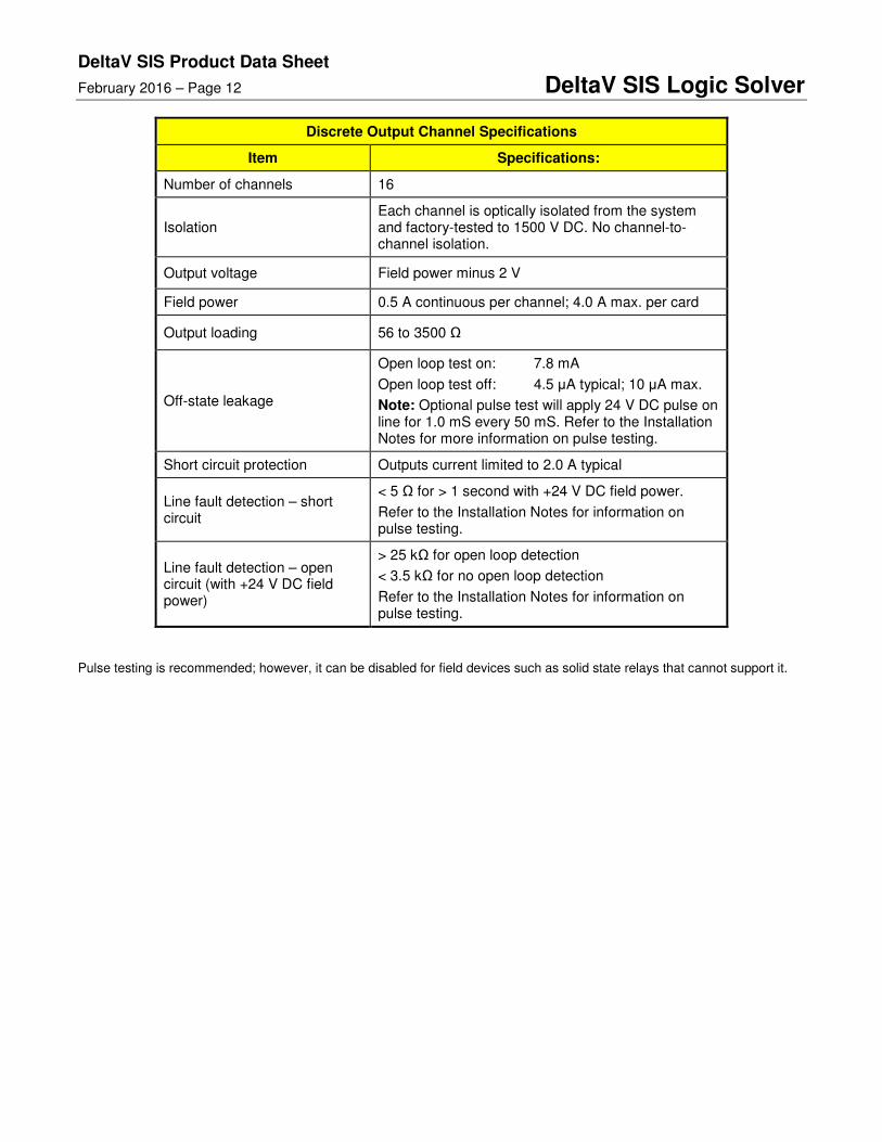
Discrete Output Channel Specifications
Item Specifications:
Number of channels 16
Isolation Each channel is optically isolated from the system and factory-tested to 1500 V DC. No channel-to-channel isolation.
Output voltage Field power minus 2 V
Field power 0.5 A continuous per channel; 4.0 A max. per card
Output loading 56 to 3500 Ω
Off-state leakage
Open loop test on: 7.8 mA
Open loop test off: 4.5 µA typical; 10 µA max.
Note: Optional pulse test will apply 24 V DC pulse on line for 1.0 mS every 50 mS. Refer to the Installation Notes for more information on pulse testing.
Short circuit protection Outputs current limited to 2.0 A typical
Line fault detection – short circuit
< 5 Ω for > 1 second with +24 V DC field power.
Refer to the Installation Notes for information on pulse testing.
Line fault detection – open circuit (with +24 V DC field power)
> 25 kΩ for open loop detection
< 3.5 kΩ for no open loop detection
Refer to the Installation Notes for information on pulse testing.
Pulse testing is recommended; however, it can be disabled for field devices such as solid state relays that cannot support it.
DeltaV SIS Product Data Sheet
February 2016 – Page 13 DeltaV SIS Logic Solver
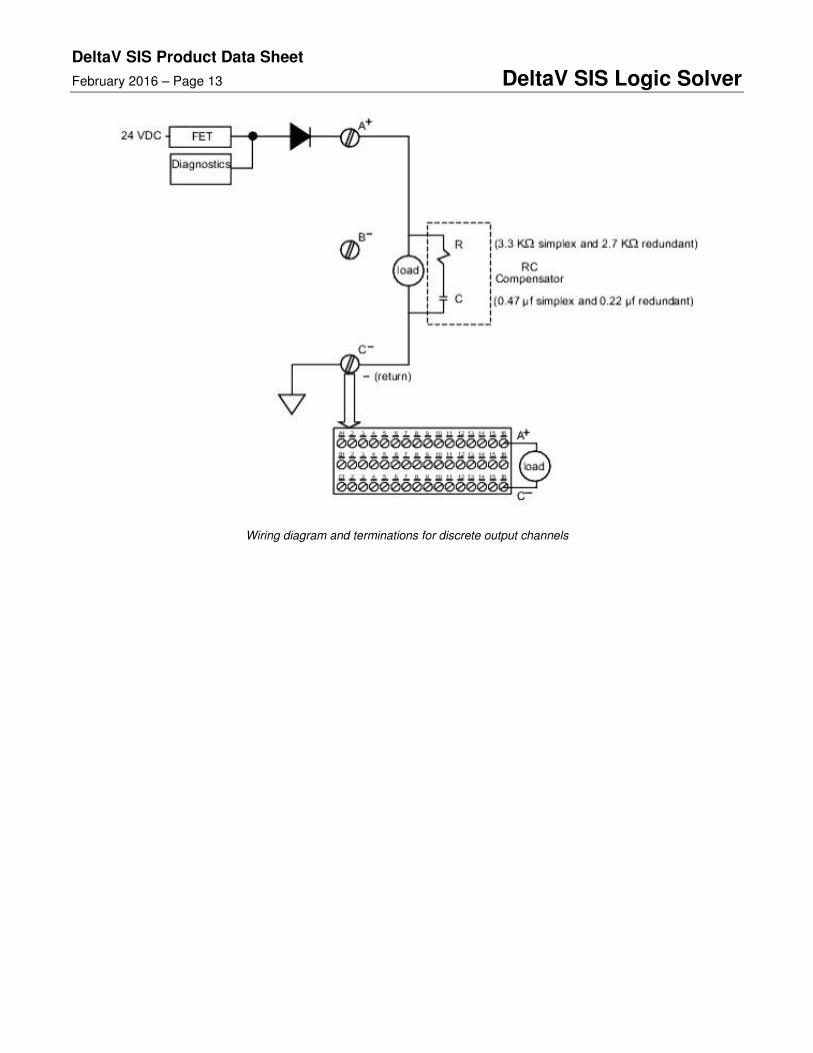
Wiring diagram and terminations for discrete output channels
DeltaV SIS Product Data Sheet
February 2016 – Page 14 DeltaV SIS Logic Solver
To locate a sales office near you, visit our website at: www.EmersonProcess.com Or call us at: India: +91 22 66620566 Asia Pacific: 65.6777.8211
Office Address: Emerson Process Management (India) Pvt. Ltd. Delphi B-Wing, 601-602, 6th Floor, Central Avenue, Hiranandani Business Park, Mumbai-400076
© Emerson Process Management 2016. All rights reserved. For Emerson Process Management trademarks and service marks, go to: http://www.emersonprocess.com/home/news/resources/marks.pdf. The contents of this publication are presented for informational purposes only, and while every effort has been made to ensure their accuracy, they are not to be construed as warrantees or guarantees, express or implied, regarding the products or services described herein or their use or applicability. All sales are governed by our terms and conditions, which are available on request. We reserve the right to modify or improve the design or specification of such products at any time without notice.
www.DeltaVSIS.com
Ordering Information
Description Model Number
DeltaV SLS 1508 Simplex Logic Solver – includes Terminal Block
CS3201
DeltaV SLS 1508 Redundant Logic Solver – includes Terminal Block
CS3202
1-wide SIS Net Terminator Assembly
(right-hand extender card and two termination resistors)
CS6051
Database Extension for SIS CS1508
8-Wide Carrier with Extend Cable Assembly
(Cable Assembly consists of left & right extender cards, 2 coax cables for Logic Solver communications bus and one cable for carrier backplane communications)
CE4050E1C2
2-Wide Carrier
(New modified 2-wide carrier containing bus terminations)
CE3051C0
Prerequisites
For DeltaV R5 English, the earliest MD or MD Plus Controllers will not support the DeltaV SIS system. Recommend to use MQ controller.