Embed Size (px)
DESCRIPTION
Demand Factor-Diversity Factor
Citation preview
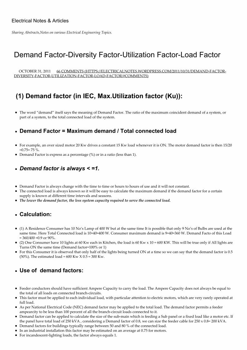
Electrical Notes & Articles
Sharing Abstracts,Notes on various Electrical Engineering Topics.
Demand Factor-Diversity Factor-Utilization Factor-Load Factor
OCTOBER 31, 2011 66 COMMENTS (HTTPS://ELECTRICALNOTES.WORDPRESS.COM/2011/10/31/DEMAND‑FACTOR‑DIVERSITY‑FACTOR‑UTILIZATION‑FACTOR‑LOAD‑FACTOR/#COMMENTS)
(1) Demand factor (in IEC, Max.Utilization factor (Ku)):
The word “demand” itself says the meaning of Demand Factor. The ratio of the maximum coincident demand of a system, orpart of a system, to the total connected load of the system.
Demand Factor = Maximum demand / Total connected load
For example, an over sized motor 20 Kw drives a constant 15 Kw load whenever it is ON. The motor demand factor is then 15/20=0.75= 75 %.Demand Factor is express as a percentage (%) or in a ratio (less than 1).
Demand factor is always < =1.
Demand Factor is always change with the time to time or hours to hours of use and it will not constant.The connected load is always known so it will be easy to calculate the maximum demand if the demand factor for a certainsupply is known at different time intervals and seasons.The lower the demand factor, the less system capacity required to serve the connected load.
Calculation:
(1) A Residence Consumer has 10 No’s Lamp of 400 W but at the same time It is possible that only 9 No’s of Bulbs are used at thesame time. Here Total Connected load is 10×40=400 W. Consumer maximum demand is 9×40=360 W. Demand Facto of this Load= 360/400 =0.9 or 90%.(2) One Consumer have 10 lights at 60 Kw each in Kitchen, the load is 60 Kw x 10 = 600 KW. This will be true only if All lights areTurns ON the same time (Demand factor=100% or 1)For this Consumer it is observed that only half of the lights being turned ON at a time so we can say that the demand factor is 0.5(50%). The estimated load = 600 Kw X 0.5 = 300 Kw.
Use of demand factors:
Feeder conductors should have sufficient Ampere Capacity to carry the load. The Ampere Capacity does not always be equal tothe total of all loads on connected branch‑circuits.This factor must be applied to each individual load, with particular attention to electric motors, which are very rarely operated atfull load. As per National Electrical Code (NEC) demand factor may be applied to the total load. The demand factor permits a feederampearcity to be less than 100 percent of all the branch‑circuit loads connected to it.Demand factor can be applied to calculate the size of the sub‑main which is feeding a Sub panel or a fixed load like a motor etc. Ifthe panel have total load of 250 kVA , considering a Demand factor of 0.8, we can size the feeder cable for 250 x 0.8= 200 kVA.Demand factors for buildings typically range between 50 and 80 % of the connected load.In an industrial installation this factor may be estimated on an average at 0.75 for motors.For incandescent‑lighting loads, the factor always equals 1.
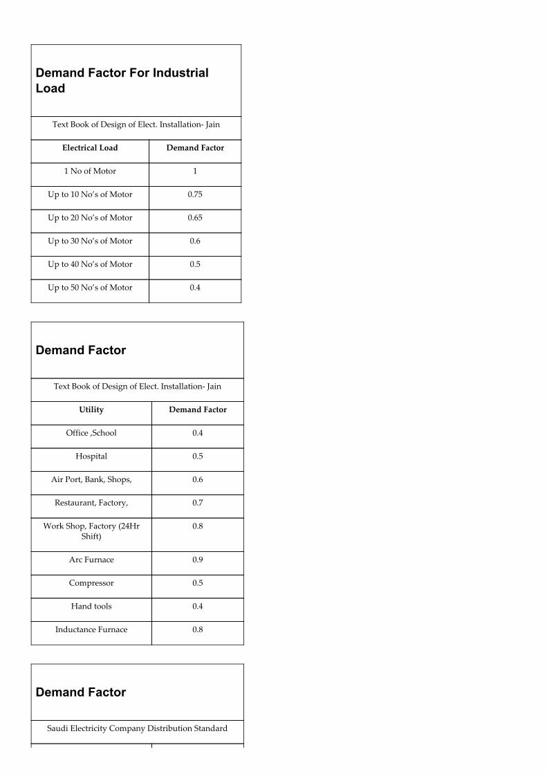
Demand Factor For IndustrialLoad
Text Book of Design of Elect. Installation‑ Jain
Electrical Load Demand Factor
1 No of Motor 1
Up to 10 No’s of Motor 0.75
Up to 20 No’s of Motor 0.65
Up to 30 No’s of Motor 0.6
Up to 40 No’s of Motor 0.5
Up to 50 No’s of Motor 0.4
Demand Factor
Text Book of Design of Elect. Installation‑ Jain
Utility Demand Factor
Office ,School 0.4
Hospital 0.5
Air Port, Bank, Shops, 0.6
Restaurant, Factory, 0.7
Work Shop, Factory (24HrShift)
0.8
Arc Furnace 0.9
Compressor 0.5
Hand tools 0.4
Inductance Furnace 0.8
Demand Factor
Saudi Electricity Company Distribution Standard
Utility Demand Factor
Residential 0.6
Commercial 0.7
Flats 0.7
Hotel 0.75
Mall 0.7
Restaurant 0.7
Office 0.7
School 0.8
Common Area in building 0.8
Public Facility 0.75
Street Light 0.9
Indoor Parking 0.8
Outdoor Parking 0.9
Park / Garden 0.8
Hospital 0.8
Workshops 0.6
Ware House 0.7
Farms 0.9
Fuel Station 0.7
Factories 0.9
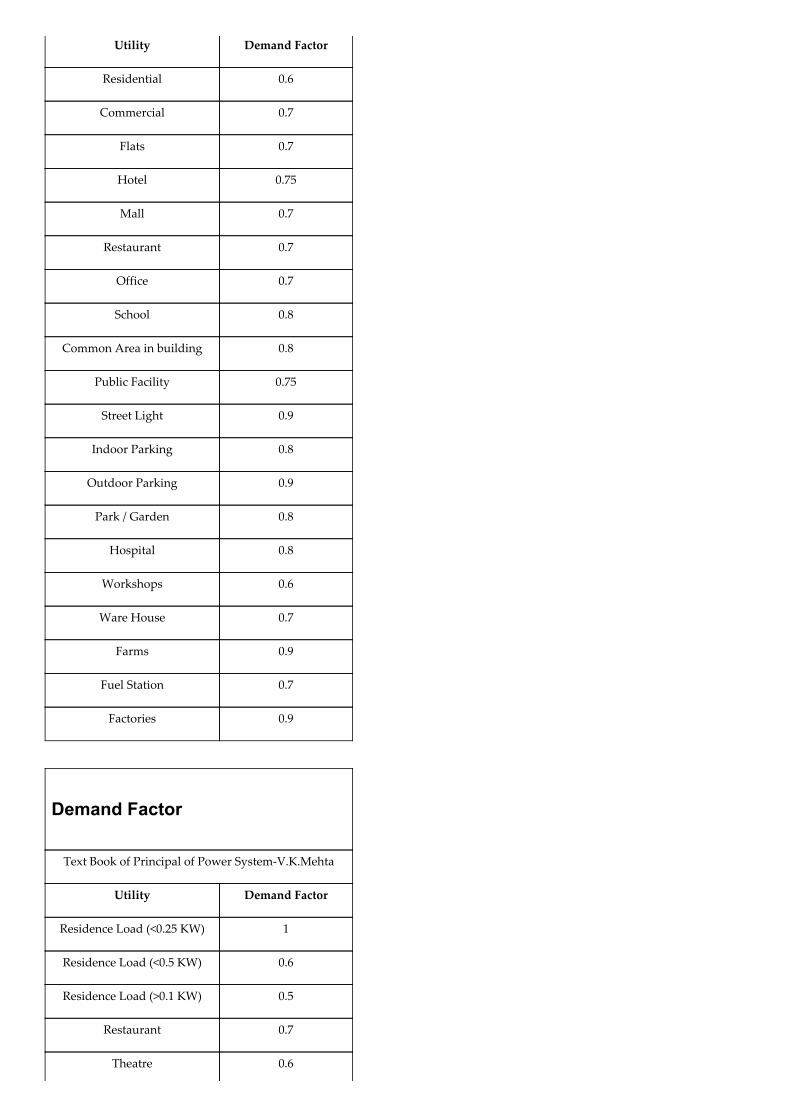
Demand Factor
Text Book of Principal of Power System‑V.K.Mehta
Utility Demand Factor
Residence Load (<0.25 KW) 1
Residence Load (<0.5 KW) 0.6
Residence Load (>0.1 KW) 0.5
Restaurant 0.7
Theatre 0.6

Hotel 0.5
School 0.55
Small Industry 0.6
Store 0.7
Motor Load (up to 10HP) 0.75
Motor Load (10HP to 20HP) 0.65
Motor Load (20HP to 100HP) 0.55
Motor Load (Above 100HP) 0.50
(2) Diversity factor:
Diversity Factor is ratio of the sum of the individual maximum demands of the various sub circuit of a system to the maximumdemand of the whole system.
Diversity Factor = Sum of Individual Maximum Demands / Maximum Demand ofthe System.
Diversity Factor = Installed load / Running load.
The diversity factor is always >= 1.
Diversity Factor is always >1 because sum of individual max. Demands >Max. Demand.In other terms, Diversity Factor (0 to 100%) is a fraction of Total Load that is particular item contributed to peak demand. 70%diversity means that the device operates at its nominal or maximum load level 70% of the time that it is connected and turnedON.It is expressed as a percentage (%) or a ratio more than 1.If we use diversity value in % than it should be multiply with Load and if we use in numerical value (>1) than it should bedivided with Load.Diversity occurs in an operating system because all loads connected to the System are not operating simultaneously or are notsimultaneously operating at their maximum rating. The diversity factor shows that the whole electrical load does not equal thesum of its parts due to this time Interdependence (i.e. diverseness).In general terms we can say that diversity factor refers to the percent of time available that a machine. 70% diversity means thatthe device operates at its nominal or maximum load level 70% of the time that it is connected and turned ON.Consider two Feeders with the same maximum demand but that occur at different intervals of time. When supplied by the samefeeder, the demand on such is less the sum of the two demands. In electrical design, this condition is known as diversity.Diversity factor is an extended version of demand factor. It deals with maximum demand of different units at a time/Maximumdemand of the entire system.Greater the diversity factor, lesser is the cost of generation of power.Many designers prefer to use unity as the diversity factor in calculations for planning conservatism because of plant load growthuncertainties. Local experience can justify using a diversity factor larger than unity, and smaller service entrance conductors andtransformer requirements chosen accordingly.The diversity factor for all other installations will be different, and would be based upon a local evaluation of the loads to beapplied at different moments in time. Assuming it to be 1.0 may, on some occasions, result in a supply feeder and equipmentrating that is rather larger than the local installation warrants, and an over‑investment in cable and equipment to handle therated load current. It is better to evaluate the pattern of usage of the loads and calculate an acceptable diversity factor for eachparticular case.
Calculation:
One Main Feeder have two Sub feeder (Sub Feeder A and Sub Feeder B), Sub Feeder‑A have demand at a time is 35 KW and SubFeeder‑B have demands at a time is 42 KW, but the maximum demand of Main Feeder is 70 KW.Total individual Maximum Demand =35+42=77 KW.Maximum Demand of whole System=70 KWSo Diversity factor of The System= 77/70 =1.1Diversity factor can shoot up above 1.
Use of diversity factor:
The Diversity Factor is applied to each group of loads (e.g. being supplied from a distribution or sub‑distribution board). Diversity factor is commonly used for a complete a coordination study for a system. This diversity factor is used to estimate theload of a particular node in the system.Diversity factor can be used to estimate the total load required for a facility or to size the TransformerDiversity factors have been developed for main feeders supplying a number of feeders, and typically 1.2 to 1.3 for ResidenceConsumer and 1.1 to 1.2 for Commercial Load. 1.50 to 2.00 for power and lighting loads.Note: Reciprocal of the above ratio (will be more than 1) also is used in some other countries.Diversity factor is mostly used for distribution feeder size and transformer as well as to determine the maximum peak load anddiversity factor is always based on knowing the process. You have to understand what will be on or off at a given time fordifferent buildings and this will size the feeder. Note for typical buildings diversity factor is always one. You have to estimate orhave a data records to create 24 hours load graph and you can determine the maximum demand load for node then you caneasily determine the feeder and transformer size.The diversity factor of a feeder would be the sum of the maximum demands of the individual consumers divided by themaximum demand of the feeder. In the same manner, it is possible to compute the diversity factor on a substation, a transmissionline or a whole utility system.The residential load has the highest diversity factor. Industrial loads have low diversity factors usually of 1.4, street lightpractically unity and other loads vary between these limits.
Diversity Factor in distribution Network
(Standard Handbook for Electrical Engineers” by Fink and Beaty)
Elements of System Residential Commercial GeneralPower Large Industrial
Between individualusers
2.00 1.46 1.45
Between transformers 1.30 1.30 1.35 1.05
Between feeders 1.15 1.15 1.15 1.05
Between substations 1.10 1.10 1.10 1.10
From users totransformers
2.00 1.46 1.44
From users to feeder 2.60 1.90 1.95 1.15
From users tosubstation
3.00 2.18 2.24 1.32
From users togenerating station
3.29 2.40 2.46 1.45
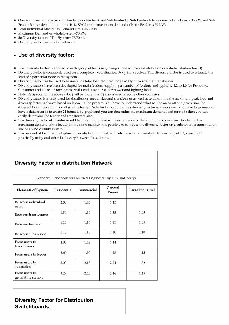
Diversity Factor for DistributionSwitchboards
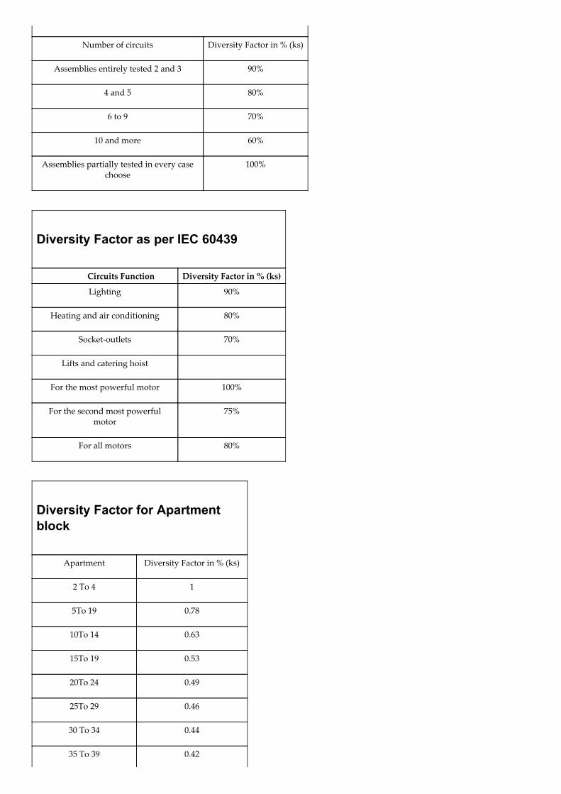
Number of circuits Diversity Factor in % (ks)
Assemblies entirely tested 2 and 3 90%
4 and 5 80%
6 to 9 70%
10 and more 60%
Assemblies partially tested in every casechoose
100%
Diversity Factor as per IEC 60439
Circuits Function Diversity Factor in % (ks)
Lighting 90%
Heating and air conditioning 80%
Socket‑outlets 70%
Lifts and catering hoist
For the most powerful motor 100%
For the second most powerfulmotor
75%
For all motors 80%
Diversity Factor for Apartmentblock
Apartment Diversity Factor in % (ks)
2 To 4 1
5To 19 0.78
10To 14 0.63
15To 19 0.53
20To 24 0.49
25To 29 0.46
30 To 34 0.44
35 To 39 0.42
40To 40 0.41
50 To Above 0.40
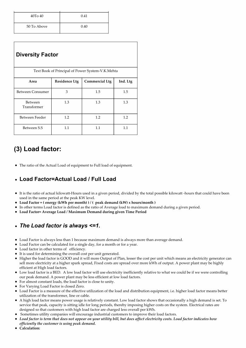
Diversity Factor
Text Book of Principal of Power System‑V.K.Mehta
Area Residence Ltg Commercial Ltg Ind. Ltg
Between Consumer 3 1.5 1.5
BetweenTransformer
1.3 1.3 1.3
Between Feeder 1.2 1.2 1.2
Between S.S 1.1 1.1 1.1
(3) Load factor:
The ratio of the Actual Load of equipment to Full load of equipment.
Load Factor=Actual Load / Full Load
It is the ratio of actual kilowatt‑Hours used in a given period, divided by the total possible kilowatt ‑hours that could have beenused in the same period at the peak KW level.Load Factor = ( energy (kWh per month) ) / ( peak demand (kW) x hours/month )In other terms Load factor is defined as the ratio of Average load to maximum demand during a given period.Load Factor= Average Load / Maximum Demand during given Time Period
The Load factor is always <=1.
Load Factor is always less than 1 because maximum demand is always more than average demand.Load Factor can be calculated for a single day, for a month or for a year.Load factor in other terms of efficiency.It is used for determining the overall cost per unit generated.Higher the load factor is GOOD and it will more Output of Plan, lesser the cost per unit which means an electricity generator cansell more electricity at a higher spark spread, Fixed costs are spread over more kWh of output. A power plant may be highlyefficient at High load factors.Low load factor is a BED. A low load factor will use electricity inefficiently relative to what we could be if we were controllingour peak demand. A power plant may be less efficient at low load factors.For almost constant loads, the load factor is close to unity.For Varying Load Factor is closed Zero.Load Factor is a measure of the effective utilization of the load and distribution equipment, i.e. higher load factor means betterutilization of the transformer, line or cable.A high load factor means power usage is relatively constant. Low load factor shows that occasionally a high demand is set. Toservice that peak, capacity is sitting idle for long periods, thereby imposing higher costs on the system. Electrical rates aredesigned so that customers with high load factor are charged less overall per kWh. Sometimes utility companies will encourage industrial customers to improve their load factors.Load factor is term that does not appear on your utility bill, but does affect electricity costs. Load factor indicates howefficiently the customer is using peak demand.Calculation:
Motor of 20 hp drives a constant 15 hp load whenever it is on. The motor load factor is then 15/20 = 75%.
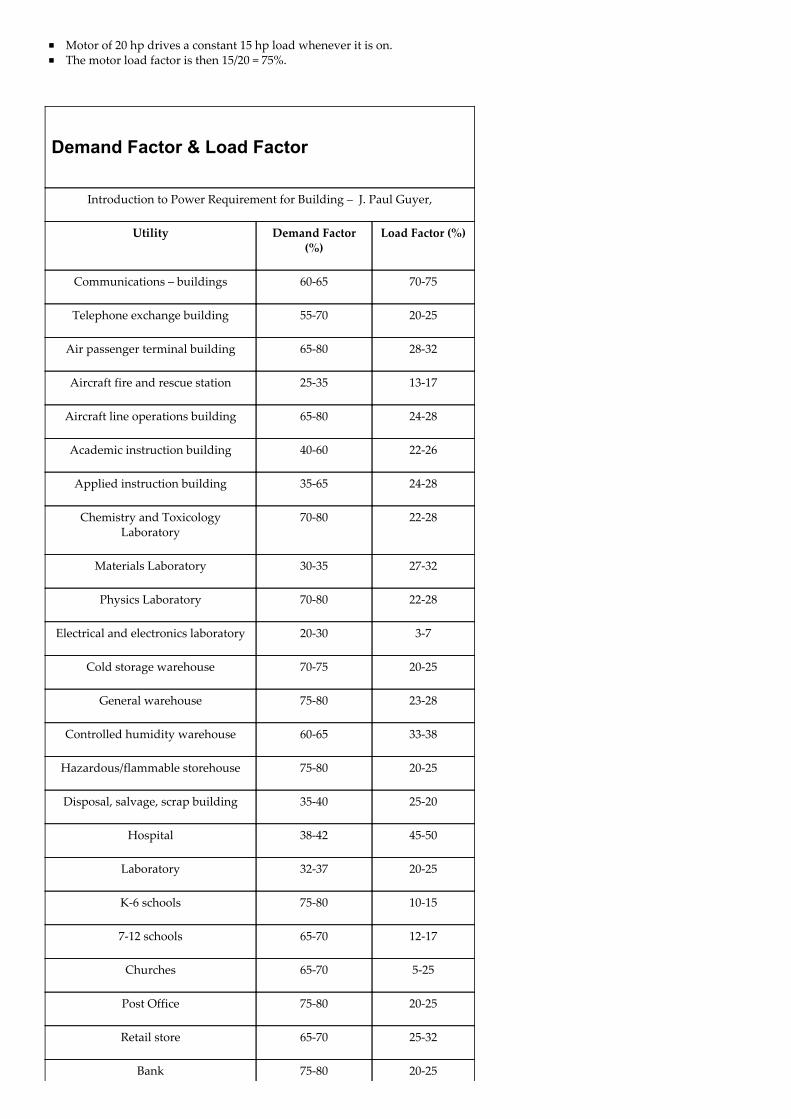
Demand Factor & Load Factor
Introduction to Power Requirement for Building – J. Paul Guyer,
Utility Demand Factor(%)
Load Factor (%)
Communications – buildings 60‑65 70‑75
Telephone exchange building 55‑70 20‑25
Air passenger terminal building 65‑80 28‑32
Aircraft fire and rescue station 25‑35 13‑17
Aircraft line operations building 65‑80 24‑28
Academic instruction building 40‑60 22‑26
Applied instruction building 35‑65 24‑28
Chemistry and ToxicologyLaboratory
70‑80 22‑28
Materials Laboratory 30‑35 27‑32
Physics Laboratory 70‑80 22‑28
Electrical and electronics laboratory 20‑30 3‑7
Cold storage warehouse 70‑75 20‑25
General warehouse 75‑80 23‑28
Controlled humidity warehouse 60‑65 33‑38
Hazardous/flammable storehouse 75‑80 20‑25
Disposal, salvage, scrap building 35‑40 25‑20
Hospital 38‑42 45‑50
Laboratory 32‑37 20‑25
K‑6 schools 75‑80 10‑15
7‑12 schools 65‑70 12‑17
Churches 65‑70 5‑25
Post Office 75‑80 20‑25
Retail store 65‑70 25‑32
Bank 75‑80 20‑25
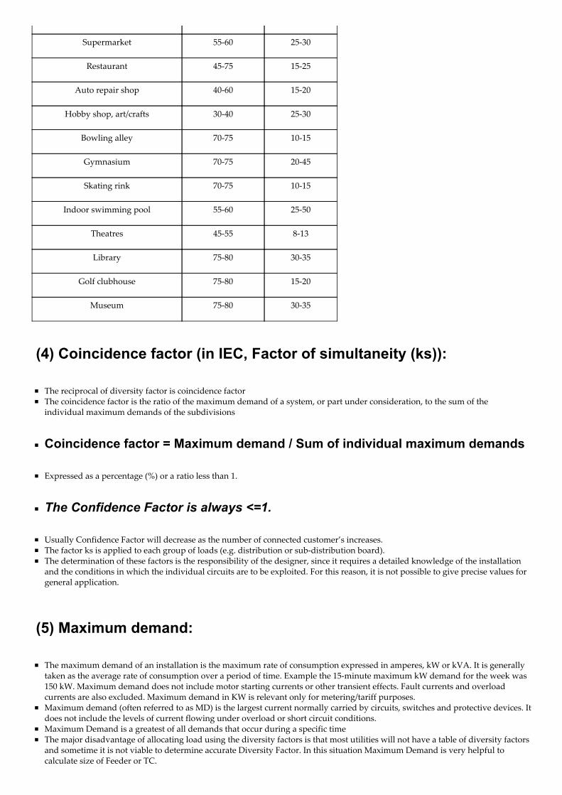
Supermarket 55‑60 25‑30
Restaurant 45‑75 15‑25
Auto repair shop 40‑60 15‑20
Hobby shop, art/crafts 30‑40 25‑30
Bowling alley 70‑75 10‑15
Gymnasium 70‑75 20‑45
Skating rink 70‑75 10‑15
Indoor swimming pool 55‑60 25‑50
Theatres 45‑55 8‑13
Library 75‑80 30‑35
Golf clubhouse 75‑80 15‑20
Museum 75‑80 30‑35
(4) Coincidence factor (in IEC, Factor of simultaneity (ks)):
The reciprocal of diversity factor is coincidence factorThe coincidence factor is the ratio of the maximum demand of a system, or part under consideration, to the sum of the individual maximum demands of the subdivisions
Coincidence factor = Maximum demand / Sum of individual maximum demands
Expressed as a percentage (%) or a ratio less than 1.
The Confidence Factor is always <=1.
Usually Confidence Factor will decrease as the number of connected customer’s increases.The factor ks is applied to each group of loads (e.g. distribution or sub‑distribution board). The determination of these factors is the responsibility of the designer, since it requires a detailed knowledge of the installationand the conditions in which the individual circuits are to be exploited. For this reason, it is not possible to give precise values forgeneral application.
(5) Maximum demand:
The maximum demand of an installation is the maximum rate of consumption expressed in amperes, kW or kVA. It is generallytaken as the average rate of consumption over a period of time. Example the 15‑minute maximum kW demand for the week was150 kW. Maximum demand does not include motor starting currents or other transient effects. Fault currents and overloadcurrents are also excluded. Maximum demand in KW is relevant only for metering/tariff purposes.Maximum demand (often referred to as MD) is the largest current normally carried by circuits, switches and protective devices. Itdoes not include the levels of current flowing under overload or short circuit conditions.Maximum Demand is a greatest of all demands that occur during a specific timeThe major disadvantage of allocating load using the diversity factors is that most utilities will not have a table of diversity factorsand sometime it is not viable to determine accurate Diversity Factor. In this situation Maximum Demand is very helpful tocalculate size of Feeder or TC.
The kVA rating of all distribution transformers is always known for a feeder. The metered readings can be taken to eachtransformer based upon the transformer rating. An “allocation factor” (AF) can be calculate.Allocation Factor= Metered Demand (KVA) / Total KVA.Equipment Demand= AF x Total KVA of Equipments
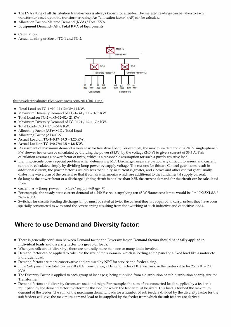
Calculation:Actual Loading or Size of TC‑1 and TC‑2.
(https://electricalnotes.files.wordpress.com/2011/10/11.jpg)
Total Load on TC‑1 =10+11+12+08= 41 KW.Maximum Diversity Demand of TC‑1= 41 / 1.1 = 37.3 KW.Total Load on TC‑2 =4+3+12+02= 21 KW.Maximum Diversity Demand of TC‑2= 21 / 1.2 = 17.5 KW.Total Load= 37.3 + 17.5 =54.8 KW.Allocating Factor (AF)= M.D / Total LoadAllocating Factor (AF)= 0.27.Actual Load on TC‑1=0.27×37.3 = 1.20 KW.Actual Load on TC‑2=0.27×17.5 = 4.8 KW. Assessment of maximum demand is very easy for Resistive Load , For example, the maximum demand of a 240 V single‑phase 8kW shower heater can be calculated by dividing the power (8 kW) by the voltage (240 V) to give a current of 33.3 A. Thiscalculation assumes a power factor of unity, which is a reasonable assumption for such a purely resistive load.Lighting circuits pose a special problem when determining MD. Discharge lamps are particularly difficult to assess, and currentcannot be calculated simply by dividing lamp power by supply voltage. The reasons for this are Control gear losses result inadditional current, the power factor is usually less than unity so current is greater, and Chokes and other control gear usuallydistort the waveform of the current so that it contains harmonics which are additional to the fundamental supply current.So long as the power factor of a discharge lighting circuit is not less than 0.85, the current demand for the circuit can be calculatedfrom:current (A) = (lamp power x 1.8) / supply voltage (V)For example, the steady state current demand of a 240 V circuit supplying ten 65 W fluorescent lamps would be: I = 10X65X1.8A /240 = 4.88ASwitches for circuits feeding discharge lamps must be rated at twice the current they are required to carry, unless they have beenspecially constructed to withstand the severe arcing resulting from the switching of such inductive and capacitive loads.
Where to use Demand and Diversity factor:
There is generally confusion between Demand factor and Diversity factor. Demand factors should be ideally applied toindividual loads and diversity factor to a group of loads.When you talk about ‘diversity’, there are naturally more than one or many loads involved.Demand factor can be applied to calculate the size of the sub‑main, which is feeding a Sub panel or a fixed load like a motor etc,individual Load.Demand factors are more conservative and are used by NEC for service and feeder sizing.If the Sub panel have total load is 250 kVA , considering a Demand factor of 0.8, we can size the feeder cable for 250 x 0.8= 200kVA.The Diversity Factor is applied to each group of loads (e.g. being supplied from a distribution or sub‑distribution board), size theTransformer.Demand factors and diversity factors are used in design. For example, the sum of the connected loads supplied by a feeder ismultiplied by the demand factor to determine the load for which the feeder must be sized. This load is termed the maximumdemand of the feeder. The sum of the maximum demand loads for a number of sub feeders divided by the diversity factor for thesub feeders will give the maximum demand load to be supplied by the feeder from which the sub feeders are derived.
Calculate Size of Electrical Switchgear by Demand & DiversityFactor:
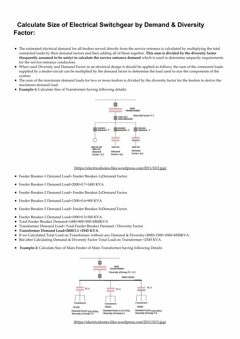
The estimated electrical demand for all feeders served directly from the service entrance is calculated by multiplying the totalconnected loads by their demand factors and then adding all of these together. This sum is divided by the diversity factor(frequently assumed to be unity) to calculate the service entrance demand which is used to determine ampacity requirementsfor the service entrance conductors.When used Diversity and Demand Factor in an electrical design it should be applied as follows, the sum of the connected loadssupplied by a feeder‑circuit can be multiplied by the demand factor to determine the load used to size the components of thesystem.The sum of the maximum demand loads for two or more feeders is divided by the diversity factor for the feeders to derive themaximum demand load.Example‑1: Calculate Size of Transformer having following details:
(https://electricalnotes.files.wordpress.com/2011/10/2.jpg)
Feeder Breaker‑1 Demand Load= Feeder Breaker‑1xDemand Factor.
Feeder Breaker‑1 Demand Load=2000×0.7=1400 KVA
Feeder Breaker‑2 Demand Load= Feeder Breaker‑2xDemand Factor.
Feeder Breaker‑2 Demand Load=1500×0.6=900 KVA
Feeder Breaker‑3 Demand Load= Feeder Breaker‑3xDemand Factor.
Feeder Breaker‑2 Demand Load=1000×0.5=500 KVATotal Feeder Breaker Demand=1400+900+500=2800KVATransformer Demand Load= Total Feeder Breaker Demand / Diversity Factor.Transformer Demand Load=2800/1.1 =2545 KVAIf we Calculated Total Load on Transformer without any Demand & Diversity=2000+1500+1000=4500KVA.But after Calculating Demand & Diversity Factor Total Load on Transformer =2545 KVA
Example‑2: Calculate Size of Main Feeder of Main Transformer having following Details:
(https://electricalnotes.files.wordpress.com/2011/10/3.jpg)

Sum of Maximum Demand of Customer on TC‑1 =10 KWx0.65 =6.5 KWSum of Maximum Demand of Customer on TC‑2 =20 KWx0.75 =15 KWSum of Maximum Demand of Customer on TC‑3 =30 KWx0.65 =19.5 KWAs Diversity of Consumer Connected on TC‑1 is 1.5 so,Maximum Demand on TC‑1 =6.5 KW/1.5 = 4 KW.As Diversity of Consumer Connected on TC‑2 is 1.1 so,Maximum Demand on TC‑2 =15 KW/1.1 = 14 KWAs Diversity of Consumer Connected on TC‑3 is 1.5 so,Maximum Demand on TC‑3 =19.5 KW/1.5 = 13 KW.Individual Maximum Demand on Main Transformer =04+14+13= 31 KW.Maximum Demand on Main Feeder =04+14+13 / 1.3 =24 KW
Significance of Load Factor and Diversity Factor
Load factor and diversity factor play an important part in the cost of the supply of electrical energy. Higher the values of loadfactor and diversity factors, lower will be the overall cost per unit generated.The capital cost of the power station depends upon the capacity of the power station. Lower the maximum demand of the powerstation, the lower is the capacity required and therefore lower is the capital cost of the plant. With a given number of consumersthe higher the diversity factor of their loads, the smaller will be the capacity of the plant required and consequently the fixedcharges due to capital investment will be much reduced.Similarly higher load factor means more average load or more number of units generated for a given maximum demand andtherefore overall cost per unit of electrical energy generated is reduced due to distribution of standing charges which areproportional to maximum demand and independent of number of units generated.Thus the suppliers should always try to improve the load factor as well as diversity factor by inducing the consumers to use theelectrical energy during off peak hours and they may be charged at lower rates for such schemes.
FILED UNDER UNCATEGORIZED
About Jignesh.ParmarJignesh Parmar has completed M.Tech (Power System Control), B.E(Electrical) from Gujarat University. He has more than 13 yearsexperience in Power Transmission‑Power Distribution‑Electrical energy theft detection‑Electrical Maintenance‑ElectricalProjects(Planning‑Designing‑coordination‑Execution). He is Presently associate with one of the leading business group as a DeputyManager at Ahmedabad,India. He is Freelancer Programmer of Advance Excel and design useful Excel Sheets of ElectricalEngineering as per IS,NEC,IEC,IEEE codes. He is technical Author for ʺElectrical Mirrorʺ and ʺElectrical Indiaʺ Magazines. He isTechnical Blogger and Familiar with English, Hindi, Gujarati, French languages. He wants to Share his experience & knowledge andhelp technical enthusiasts to find suitable solutions and updating themselves on various Engineering Topics.
66 Responses to Demand Factor-Diversity Factor-Utilization Factor-Load Factor
Manish says:October 31, 2011 at 4:14 pmThank you very much for such a good and detailed article.Your blog posts are always quite good !
ReplyDieter says:November 9, 2011 at 10:55 amAs a junior E&I Engineer, I herewith thank you for your kindness of sharing your knowledge.
I look foreward to more of your work.
You May Like
1.
About these ads (https://wordpress.com/about-these-ads/)

ReplyS.SAMBATH says:November 29, 2011 at 1:36 pmSir,The informations are very useful like me as Electricity Board Engineer. Thank u and I expect more.s.sambath
Replyzaheer khattak says:May 30, 2012 at 7:15 amdear sir, thanks a lot both of u i am electrical engineer and i m working in consultancy firm in pakistani mostly design high rise official and residential building. i want to share and gain some important knowledge aboutdesigning for All of u and every one how help me.thanksZaheer khattakshaz consultant Peshawar Pakistan
available on Facebook
chemie says:November 30, 2011 at 6:21 amme from malaysia… u are great sir.. thanks a lot
ReplyMd.Samiuddin says:December 7, 2011 at 8:58 amDear Mr. Jignesh Parmar,
The details provided by are very useful. Excellent!
I need a small help. I am an Indian, native of Andhra Pradesh. I am a mechanical engineer, handling a new project in Jeddah,Saudi Arabia.The details in the power summary report are:Connected Power Usage = 1290KWHAfter multiplying by power factors and maximum utilization factors individually to each equipment the sum is = 535 KWH.Example: Crane connected power = 95 kwh; power factor = 0.6; Max. Utlzn. Factor= 0.75 gives 95kwh X 0.6 X 0.75 = 42.75kwh
Now, If I want buy the generators (OR) to ask for electricity dept. what power should I ask? Will it be 1290KWH or 535 KWH?Please clarify and explain me to improve my awaeness in this perticular topic because always I come across with such incidents.
Please reply to me to my email: (or)
Thanks for your support in advance.
Best Regard
Md.SamiuddinPlant managerMIM Co.,JeddahKSA
ReplyMansour A, says:January 15, 2012 at 7:08 pmThank u very much Mr. Parmar, I really get use and understand these factors which were confused to me. I have set this site infavourities looking foreward to read your good activities.
Replyfrancis azumah says:February 18, 2012 at 2:49 pmam very greatful for the explanatory notes, i say well done but needs more of that. thank you
ReplyRahman says:February 27, 2012 at 11:49 amvery useful link thank you
Replyopeyemi says:March 17, 2012 at 6:32 amGreat answer,it really meet my demand
Replyranx says:March 23, 2012 at 6:57 pmThank for your kindness, your explanation very useful and very understadble to us….
Replyranx says:March 23, 2012 at 6:58 pmThanks for the sharing of your knowledge this s very useful to my design…
Replyanam says:April 25, 2012 at 1:03 pmcan i have the definition of growth factor?
Replygoldwincs says:June 18, 2012 at 2:42 pmgreat post! can you explain about peak diversity factor?
Replyahmed nazmi says:July 19, 2012 at 9:05 amwhat the difference between diversity factor and diversity factor (ks) and where i will use :diversity factor , diversity factor (ks)and demand factor
Replydaniel says:August 8, 2012 at 5:45 pmgreat, please do more post and detailed explanation
Replymy name is okekhian stanley. says:August 16, 2012 at 2:34 pmThank you for your knowledge. This will be of help in my field work.
Replykwame says:August 16, 2012 at 2:57 pmThanks very much, I am really enlightened alot.
ReplyJose Antonio Martins says:September 28, 2012 at 6:06 pmDear Mr. Jignesh Parmar,
The details provided about this issue are very useful.
Would you mind informing me about the origin of the table: “Diversity Factor for an apartment block”?
Please answer me by email.
Thanks for your support in advance.
ReplyJose Antonio Martins says:December 19, 2012 at 8:21 pmI have already found the referred table in the French Standard “NF C 14‑100 (2008): Low‑voltage mains installations”.Please consider the corrections:– where is “40To 40” should be “40 to 49”– where is “50 To Above, ks = 0.40” should be “50 to Above, ks = 0.38”.
Replydhananjay Prasad says:October 12, 2012 at 2:18 amThank you sir
Replysalman p says:November 7, 2012 at 8:16 amthank u sir

Replytiger says:November 19, 2012 at 11:05 amVery good article , but these calculation derived from which Code or standard ??? specially table (Demand Factor & Load Factoraccording to Type of Industries) , because these values is varied and depend on the practice wise
ReplyJignesh.Parmar says:November 19, 2012 at 2:35 pmYes. Agree with you. This is just reference Value .This Value vary according to it’s user’s Profile.We can not predict the actual value but this table value helpful us to calculate more realistic assumption.I got this Table from one Book or Manual. If it is more valuable for You than I will defiantly convey it’s Reference Source.
Replytiger man says:November 20, 2012 at 7:48 amMany thanks for your reply , and i hope to send to me this reference or book it will be a kind from you
Samer says:January 2, 2013 at 9:10 amCan you please provide me with the reference source? It is very important to me.Thank you for the great article.Regards.
Ron Chatterji says:December 5, 2012 at 1:26 pmI am from US. My name is Ron. I want to talk with you on something. Please tell me what phone # I can call and time. I will callyou after getting your 3
ReplyJignesh.Parmar says:December 5, 2012 at 2:20 pmI am available on Email.My Email Id is [email protected]
ReplyMohammed says:February 24, 2013 at 4:16 pmDear Jignesh, i need the references of your diversity , demand and coincidence factros tables. are they as per anyinternational / national codes. Your kind reply will bne helful in studying a project.
M.A.Bari
Shakil says:July 6, 2013 at 2:49 amJignesh.Parmar,I need your help.I am fm Bangladesh.Iam also a electrical engineer.I saw that you have most experience inpower sector.In15th july,a Bangladeshi power generation company call a interview.I am also a candidate for thatinterview.Sir please give some materials and tell me how can i got that job.I like to inform you that,I have no experience towork any power plant.I am a fresher electrical engineer
Ron Chatterji says:December 5, 2012 at 1:27 pmI need your phone # and the time/date
Replyminhaz says:December 23, 2012 at 5:00 amexellent
Replysaad says:December 23, 2012 at 9:31 amthanks dear
ReplyMark Jason Acopio Obordo says:January 17, 2013 at 2:08 pmthanks!!now i know.:)
Replycolin challinger says:February 5, 2013 at 9:59 am
Hi I have an appartment block with 12 flats to cost and they are all electrily heated toal pot divesity equals 22.4 Kvaref to (ks) will this factor still apply to the incoming main?
ReplyPercy Makhuvha says:February 28, 2013 at 8:28 amThank you very much know I am happy
ReplyAllan Sanjose says:March 18, 2013 at 12:32 amYour first statement regarding demand factor is always less than one.
if your demand factor is 100% that is equal to one.
Philippines
ReplyJignesh.Parmar says:March 18, 2013 at 2:25 pmPlease carefully Read Definition First !!!Demand Factor = Maximum demand of a system / Total connected load on the system.Your max demand never goes beyond connected load so D.F is always less than 1.Hope this clarification may clear your dough.
ReplyRahul says:March 21, 2013 at 5:22 pmDear sir,
I came across another formula like
Maximum normal running plant load = 100% sum of all continuously operating loads + 30% sum of all intermittent loads.
Where 100% and 30% are considered as the diversity factors of continuous and intermittent loads respectively
Sir do you know which industry is this formula commonly used. can you explain this formula..
I hope you will reply to my question
ReplyKhwaja Salim says:April 3, 2013 at 9:36 amThank You Mr. Jignesh Parmar. It is very useful in designing of electrical installtion.
ReplyJohn says:May 11, 2013 at 2:52 pmDear Sir, I would like to learn about the reference for this info.Thank you very much for your kind help.
Replyavtar singh says:May 27, 2013 at 10:44 amDear sir, one confusion is that if my conected load is 450 kw and consumption is 307 kwh then what the rating of incommingtransformer please tell me brief.
ReplyBala says:September 22, 2013 at 5:56 amThank You Mr.Jignesh Parmar.
Replyprit chitroda says:October 3, 2013 at 6:04 pmvery usefull things u have given, thanks,
Replysaad says:November 2, 2013 at 8:04 amthank you very much.
Replya test says:

November 12, 2013 at 7:52 amthis is a test
Replyaki says:November 25, 2013 at 8:17 amthank uuu
Replyhaseebullha says:November 25, 2013 at 12:51 pmnice and simple information thanks for your effort
Replyirdan ray bodiongan says:January 17, 2014 at 8:44 amwhat is the demand factor and load factor for drafting room?
ReplyAlberto Gasmen says:February 24, 2014 at 8:21 pmBasically, these data for the DEMAND and DIVERSITY factors are excellent info for a fast estimation of POWER SUPPLY,CABLE / WIRE SIZES, many thanks
Replysouvik says:March 22, 2014 at 8:56 amthanks for the article….. it helped me. thanks
ReplyS P Sarathy says:March 23, 2014 at 12:46 pmYour effort is laudable. We stand to gain with your sharing in a simple way.
Replyashok chaudhary says:September 7, 2014 at 6:00 amthanks for useful And applicable knowlge
ReplyHarish Kumar Johri says:September 8, 2014 at 5:10 amThank you Mr. Jignesh! Nice explanations of these Electricity factors in one Article.Harish Kumar Johri, L&T Faridabad.
ReplyRafiq says:September 21, 2014 at 5:55 pmThanks for this note, hopefully can i know what is your reference for this … Im glad to know…thanks in advance
ReplyGodfrey says:November 15, 2014 at 8:45 amAm appreciation for this provision of the infomatiom about diversity factor bcause its always difficult to find reliable notes forthis topic.
ReplyDaramola Dele says:November 23, 2014 at 7:00 amyour article is always edifying my studies. May God Bless you more and more
ReplyDaramola Dele says:November 24, 2014 at 10:06 amhow can get this paper
ReplyMahmoud Elghazaly says:December 29, 2014 at 11:14 amthank you very much for such valuable informations
ReplyRajesh says:January 19, 2015 at 12:12 pmVery simple explanation and really valuable .This is an antibiotic for my knowledge
Replyzak says:March 2, 2015 at 12:57 pmdear Jignesh
i have a small question regarding the transformers.i need to know according to NEC what is the percentage to be loaded for the capacity of a transformer.As a practice we always consider 80% of total kva of a transformer.ex. if we have 1600 kva t/r then we can use 1600*80% = 1280 kva.we can use only 1280kva instead of 1600 kva. supoose your total load is 1400 kva then you have to go to higher size that is 2000kva.
Replyusman says:April 2, 2015 at 7:12 amnice effort for making it understandable to non technical also..
ReplyRAJNISH KUMAR says:April 22, 2015 at 9:30 amSir ,thanks for providing useful information as it helps in preparation of amie
Replymonaco del pasao says:June 16, 2015 at 5:38 amgreat notes but alot of spelling mistakes
Replyavnish kumar says:July 6, 2015 at 9:41 ami am plant engineer(electrcial).dis concept always we r using, so undestand the LF,DF etc..
Replythong raty says:August 4, 2015 at 8:46 amDear sir,
Actually sir, Could you please more detail for me about what is the Ku and What is the Ks cos i still confuse with what youshowed above.
Best regard,
Reply
Create a free website or blog at WordPress.com.
The Enterprise Theme.
Follow
Follow “Electrical Notes & Articles”
Build a website with WordPress.com