Embed Size (px)
Citation preview
DIVISION • FORD MOTOR COMPANY
Copyright © 2011, Forel Publishing Company, LLC, Woodbridge, Virginia
All Rights Reserved. No part of this book may be used or reproduced in any manner whatsoever without written permission of Forel Publishing Company, LLC. For information write to Forel
Publishing Company, LLC, 3999 Peregrine Ridge Ct., Woodbridge, VA 22192
1957 Ford Truck Shop Manual EAN: 978-1-60371-066-4
ISBN: 1-60371-066-3
Forel Publishing Company, LLC 3999 Peregrine Ridge Ct. Woodbridge, VA 22192
Email address: [email protected] Website: http://www.ForelPublishing.com
This publication contains material that is reproduced and distributed under a license from Ford Motor Company. No further reproduction or distribution of the Ford Motor Company material is
allowed without the express written permission of Ford Motor Company.
NNoottee ffrroomm tthhee PPuubblliisshheerr This product was created from the original Ford Motor Company’s publication. Every effort has been made to use the original scanned images, however, due to the condition of the material; some pages have been modified to remove imperfections.
Disclaimer
Although every effort was made to ensure the accuracy of this book, no representations or warranties of any kind are made concerning the accuracy, completeness or suitability of the information, either expressed or implied. As a result, the information contained within this book should be used as general information only. The author and Forel Publishing Company, LLC shall have neither liability nor responsibility to any person or entity with respect to any loss or damage caused, or alleged to be caused, directly or indirectly by the information contained in this book. Further, the publisher and author are not engaged in rendering legal or other professional services. If legal, mechanical, electrical, or other expert assistance is required, the services of a competent professional should be sought.
fOREWORD This manual has been prepared to provide information for the
proper servicing of 1957 Ford Trucks. Body information on the
Ranchero has also been included. Other information for servicing
the Ranchero is the same as for the 1957 Ford Car and can be found
in the 1957 Ford Car and Thunderbird Shop Manual. Service in
formation on the Fordomatic transmission may be found in the
1956-57 Fordomatic Shop Manual.
The manual is divided into 13 parts as designated on the title
page. At the beginning of each part is a title page which lists the
chapters and the sections included. The heading on each left-hand
or even-numbered page indicates the name of the chapter, and the
heading on each right-hand or odd-numbered page indicates the
section covered.
The descriptions and specifications contained in this manual
were in effect at the time the book was approved for printing. Ford
Division of Ford Motor Company reserves the right to discontinue
models at any time, or change specifications or design, without notice
and without incurring obligation.
SERVICE DEPARTMENT
FORD DIVISION FORD MOTOR COMPANY
1957 FORD TRUCK
SHOP MANUAL PART 1 ENGINES
Chapter 1 GENERAL ENGINE SERVICE
Section
1. General Engine Trouble Shooting ....... . 2. Tune-up ... " ............ " .......... . 3. Manifolds and Exhaust Gas Control V:alve 4. Rocker Arm Assembly, Push Rods, '.
and Cylinder Heads ................ . 5. Valve Mechanism ..................... . 6. Timing Chain, Timing Gears, Camshaft,
and Bearings ...................... . 7. Crankshaft and Main Bearings ......... . 8. Flywheel ............................ . 9. Connecting Rods and Bearings ......... .
10. Pistons, Pins, and Rings ............... . 11. Cylinder Block ....................... . 12. Oil Pan and Oil Pump ................. . 13. Exhaust System ...................... . 14. Engine Dimensions, and Clearance
and Adjustment Specifications ....... .
Chapter 2 6-CYLINDER ENGINES
Section
Page
1-2 1-6 1-8
1-9 1-12
1-17 1-19 1-23 1-23 1-25 1-27 1-29 1-30
1-30
1. Description. . . . . . . . . . . . . . . . . . . . . . . . . .. 1-37 2. Engine Removal and Installation ........ 1-40 3. Engine Supports ....................... 1-42 4. Manifolds and Exhaust Gas Control Valve 1-43 5. Cylinder Head and Valves .............. 1-44 6. Crankshaft Damper, Cylinder Front
Cover, and Crankshaft Oil Seal. . . . . .. 1-47 7. Sprockets and Timing Chain, Camshaft,
Bearings, and Tappets. . . . . . . . . . . . . .. 1-48 8. Flywheel, Crankshaft, and Main Bearings. 1-50 9. Connecting Rods and Bearings, Pistons,
Pins, and Rings. . . . . . . . . . . . . . . . . . .. 1-53 10. Oil Pan, Oil Filter, and Oil Pump ........ 1-55 11. Exhaust System. . . . . . . . . . . . . . . . . . . . . .. 1-56 12. General Specifications-6-Cylinder
Engines. . . . . . . . . . . . . . . . . . . . . . . . . .. 1-57
Chapter 3 a-CYLINDER ENGINES
Section
1. Description. . . . . . . . . . . . . . . . . . . . . . . . . .. 1-59 2. Engine Removal and Installation ........ 1-63 3. Engine Supports. . . . . . . . . . . . . . . . . . . . . .. 1-66 4. Manifolds and Exhaust Gas Control Valve 1-67 5. Cylinder Heads and Valves ............. 1-68 6. Crankshaft Damper, Cylinder Front
Cover, and Crankshaft Oil Seal. ...... 1-71 7. Sprockets and Timing Chain, Timing
Gears, Camshaft, Bearings, and Tappets ........................... 1-73
8. Flywheel, Crankshaft, and Main Bearings. 1-78 9. Connecting Rods and Bearings, Pistons,
Pins, and Rings. . . . . . . . . . . . . . . . . . .. 1-81 10. Oil Pan, Oil Filter, and Oil Pump ........ 1-83 11. Exhaust System ...... , ................ 1-84 12. General Specifications-8-Cylinder
Engines. . . . . . . . . . . . . . . . . . . . . . . . . .. 1-85
I
1-2
Part 1-ENGINES Chapter 1
GENERAL ENGINE SERVICE Section Page
1 2 3 4 5 6 7 8 9
General Engine Trouble Shooting ...................................................... . 1-2 1-6 1-8 1-9 1-12 1-17 1-19 1-23 1-23 1-25 1-27 1-29 1-30 1-30
Tune-Up .......................................................................... . Manifolds and Exhaust Gas Control Valve ............................................... . Rocker Arm Assembly, Push Rods, and Cylinder Heads .................................... . Valve Mechanism ................................................................... . Timing Chain, Timing Gears, Camshaft, and Bearings ... ' ................................. . Crankshaft and Main Bearings ........................................................ . Flywheel .......................................................................... . Connecting Rods and Bearings ........................................................ .
10 11 12 13 14
Pistons, Pins, and Rings .............................................................. . Cylinder Block ..................................................................... . Oil Pan and Oil Pump ............................................................... . Exhaust System .................................................................... . Engine Dimensions, and Clearance and Adjustment Specifications ............................ .
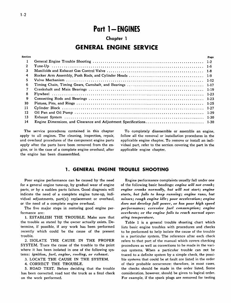
The service procedures contained in this chapter apply to all engines. The cleaning, inspection, repair, and overhaul procedures of the component engine parts apply after the parts have been removed from the engine, or in the case of a complete engine overhaul, after the engine has been disassembled.
To completely disassemble or assemble an engine, follow all the removal or installation procedures in the applicable engine chapter. To remove or install an individual part, refer to the section covering the part in the applicable engine chapter.
1. GENERAL ENGINE TROUBLE SHOOTING
Poor engine performance can be caused by the need for a general engine tune-up, by gradual wear of engine parts, or by a sudden parts failure. Good diagnosis will indicate the need of a complete engine tune-up, individual adjustments, part(s) replacement or overhaul, or the need of a complete engine overhaul.
The five major steps in restoring good engine performance are:
1. ESTABLISH THE TROUBLE. Make sure that the trouble as stated by the owner actually exists. Determine, if possible, if any work has been performed recently which could be the cause of the present trouble.
2. ISOLATE THE CAUSE IN THE PROPER SYSTEM. Trace the cause of the trouble to the point where it has been isolated in one of the following systems: ignition, fllPI, engint" cooling, or exlulU.d.
3. LOCATE THE CAUSE IN THE SYSTEM. 4. CORRECT THE TROUBLE. 5. ROAD TEST. Before deciding that the trouble
has been corrected. road test the truck as a final check on the work performed.
Engine performance complaints usually fall under one of the following basic headings: engine will not crank; engine cranks 'IOrmally, but will not start; engine slarts, but fails to keep running; engine runs, but misses; rough engine i(lle; poor acceleration; engine does not det'elop full power, or has poor high speed performance; exce.'isive fuel consumption; engine overheats; or the engine fails to reach normal operating temperature.
Table 1 is a general trouble shooting chart which lists basic engine troubles with procedures and checks to be performed to help isolate the cause of the trouble in a particular system. The reference after each check refers to that part of the manual which covers checking procedures as well as corrections to be made in the various systems. When a particular trouble can not be traced to a definite system by a simple check, the possible systems that could be at fault are listed in the order of their probable occurrence; therefore, in most cases, the checks should be made in the order listed. Some consideration, however, should be given to logical order. For example, if the spark plugs are removed for testing
Section 1-General Engine Trouble Shooting 1-3
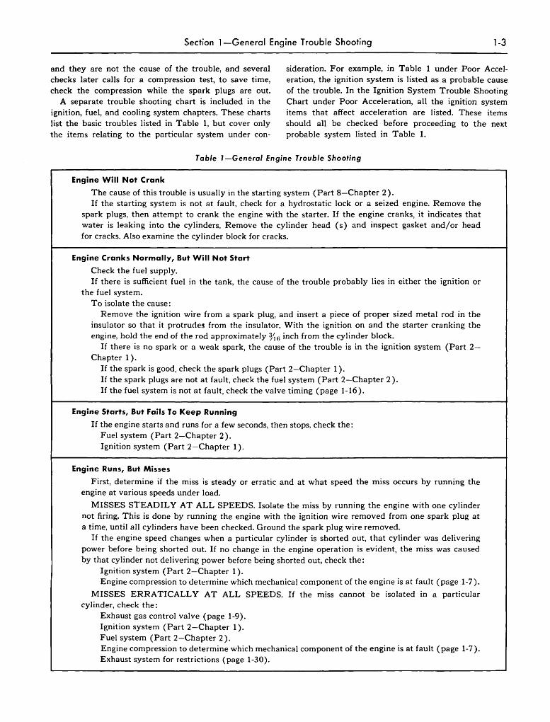
and they are not the cause of the trouble, and several checks later calls for a compression test, to save time, check the compression while the spark plugs are out.
A separate trouble shooting chart is included in the ignition, fuel, and cooling system chapters. These charts list the basic troubles listed in Table 1, but cover only the items relating to the particular system under con-
sideration. For example, in Table 1 under Poor Acceleration, the ignition system is listed as a probable cause of the trouble. In the Ignition System Trouble Shooting Chart under Poor Acceleration, all the ignition system items that affect acceleration are listed. These items should all be checked before proceeding to the next probable system listed in Table 1.
Table l-General Engine Trouble Shooting
Engine Will Not Crank
The cause of this trouble is usually in the starting system (Part 8-Chapter 2). If the starting system is not at fault, check for a hydrostatic lock or a seized engine. Remove the
spark plugs, then attempt to crank the engine with the starter. If the engine cranks, it indicates that water is leaking into the cylinders. Remove the cylinder head (s) and inspect gasket and/or head for cracks. Also examine the cylinder block for cracks.
Engine Cranks Normally, But Will Not Start
Check the fuel supply. If there is sufficient fuel in the tank, the cause of the trouble probably lies in either the ignition or
the fuel system. To isolate the cause:
Remove the ignition wire from a spark plug, and insert a piece of proper sized metal rod in the insulator so that it protrudes from the insulator. With the ignition on and the starter cranking the engine, hold the end of the rod approximately ~~6 inch from the cylinder block.
If there is no spark or a weak spark, the cause of the trouble is in the ignition system (Part 2-Chapter 1).
If the spark is good, check the spark plugs (Part 2-Chapter 1). If the spark plugs are not at fault, check the fuel system (Part 2-Chapter 2). If the fuel system is not at fault, check the valve timing (page 1-16).
Engine Starts, But Fails To Keep Running
If the engine starts and runs for a few seconds, then stops, check the: Fuel system (Part 2-Chapter 2). Ignition system (Part 2-Chapter 1).
Engine Runs, But Misses
First, determine if the miss is steady or erratic and at what speed the miss occurs by running the engine at various speeds under load.
MISSES STEADILY AT ALL SPEEDS. Isolate the miss by running the engine with one cylinder not firing. This is done by running the engine with the ignition wire removed from one spark plug at a time, until all cylinders have been checked. Ground the spark plug wire removed.
If the engine speed changes when a particular cylinder is shorted out, that cylinder was delivering power before being shorted out. If no change in the engine operation is evident, the miss was caused by that cylinder not delivering power before being shorted out, check the:
Ignition system (Part 2-Chapter 1). Engine compression to determine which mechanical component of the engine is at fault (page 1-7).
MISSES ERRA TICALL Y AT ALL SPEEDS. If the miss cannot be isolated in a particular cylinder, check the:
Exhaust gas control valve (page 1-9). Ignition system (Part 2-Chapter 1). Fuel system (Part 2-Chapter 2). Engine compression to determine which mechanical component of the engine is at fault (page 1-7). Exhaust system for restrictions (page 1-30).
'-4 Chapter l-General Engine Service
Table l-General Engine Trouble Shooting (cont'dJ
Engine Runs, But Misses (cont'd)
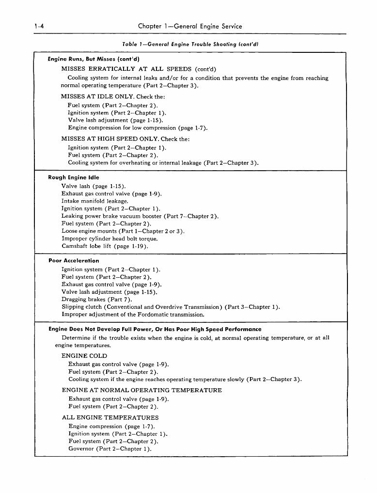
MISSES ERRATICALLY AT ALL SPEEDS (cont'd)
Cooling system for internal leaks and/or for a condition that prevents the engine from reaching normal operating temperature (Part 2-Chapter 3).
MISSES AT IDLE ONLY. Check the:
Fuel system (Part 2-Chapter 2). Ignition system (Part 2-Chapter 1). Valve lash adjustment (page 1-15). Engine compression for low compression (page l-7).
MISSES AT HIGH SPEED ONLY. Check the:
Ignition system (Part 2-Chapter 1). Fuel system (Part 2-Chapter 2). Cooling system for overheating or internal leakage (Part 2-Chapter 3).
Rough Engine Idle
Valve lash (page 1-15). Exhaust gas control valve (page 1-9). Intake manifold leakage. Ignition system (Part 2-Chapter 1). Leaking power brake vacuum booster (Part 7-Chapter 2). Fuel system (Part 2-Chapter 2). Loose engine mounts (Part I-Chapter 2 or 3). Improper cylinder head bolt torque. Camshaft lobe lift (page 1-19).
Poor Acceleration
Ignition system (Part 2-Chapter 1). Fuel system (Part 2-Chapter 2). Exhaust gas control valve (page 1-9). Valve lash adjustment (page 1-15). Dragging brakes (Part 7). Slipping clutch (Conventional and Overdrive Transmission) (Part 3-Chapter 1). Improper adjustment of the Fordomatic transmission.
Engine Does Not Develop Full Power, Or Has Poor High Speed Performance
Determine if the trouble exists when the engine is cold, at normal operating temperature, or at all engine temperatures.
ENGINE COLD
Exhaust gas control valve (page 1-9). Fuel system (Part 2-Chapter 2). Cooling system if the engine reaches operating temperature slowly (Part 2-Chapter 3).
ENGINE AT NORMAL OPERATING TEMPERATURE
Exhaust gas control valve (page 1-9). Fuel system (Part 2-Chapter 2).
ALL ENGINE TEMPERATURES
Engine compression (page 1-7). Ignition system (Part 2-Chapter 1). Fuel system (Part 2-Chapter 2). Governor (Part 2-Chapter 1).
Section l-General Engine Trouble Shooting
Table J -General Engine Trouble Shooting (conf'dJ
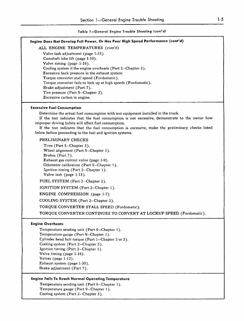
Engine Does Not Develop Full Power, Or Has Poor High Speed Performance (cont'd)
ALL ENGINE TEMPERATURES (cont'd)
Valve lash adjustment (page 1-15). Camshaft lobe lift (page 1-19). Valve timing (page 1-16). Cooling system if the engine overheats (Part 2-Chapter 3). Excessive back pressure in the exhaust system. Torque converter stall speed (Fordomatic). Torque converter fails to lock up at high speeds (Fordomatic). Brake adjustment (Part 7). Tire pressure (Part s-Chapter 3). Excessive carbon in engine.
Excessive Fuel Consumption
Determine the actual fuel consumption with test equipment installed in the truck. If the test indicates that the fuel consumption is not excessive, demonstrate to the owner how
improper driving habits will affect fuel consumption. If the test indicates that the fuel consumption is excessive, make the preliminary checks listed
below before proceeding to the fuel and ignition systems.
PRELIMINARY CHECKS
Tires (Part s-Chapter 3). Wheel alignment (Part s-Chapter 1). Brakes (Part 7). Exhaust gas control valve (page 1-9). Odometer calibration (Part 9-Chapter 1). Ignition timing (Part 2-Chapter 1). Valve lash (page 1-15).
FUEL SYSTEM (Part 2-Chapter 2).
IGNITION SYSTEM (Part 2-Chapter 1).
ENGINE COMPRESSION (page 1-7).
COOLING SYSTEM (Part 2-Chapter 3).
TORQUE CONVERTER STALL SPEED (Fordomatic).
TORQUE CONVERTER CONTINUES TO CONVERT AT LOCKUP SPEED (Fordomatic).
Engine Overheats
Temperature sending unit (Part 9-Chapter 1). Temperature gauge (Part 9-Chapter 1). Cylinder head bolt torque (Part I-Chapter 2 or 3). Cooling system (Part 2-Chapter 3). Ignition timing (Part 2-Chapter 1). Valve timing (page 1-16). Valves (page 1-12). Exhaust system (page 1-30). Brake adjustment (Part 7).
Engine Fails To Reach Normal Operating Temperature
Temperature sending unit (Part 9-Chapter 1). Temperature gauge (Part 9-Chapter 1). Cooling system (Part 2-Chapter 3).
1-5
1-6 Chapter l-General Engine Service
2. TUNE-UP
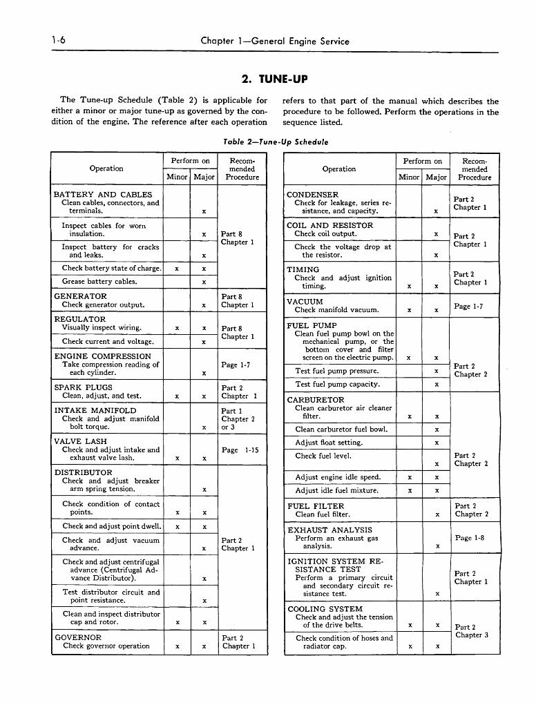
The Tune-up Schedule (Table 2) is applicable for either a minor or major tune-up as governed by the condition of the engine. The reference after each operation
refers to that part of the manual which describes the procedure to be followed. Perform the operations in the sequence listed.
Table 2-Tune-Up Schedule
Perform on Recom- Perform on Recom-Operation mended Operation mended
Minor Major Procedure Minor Major Procedure
BATTERY AND CABLES Clean cables, connectors, and
terminals. x
CONDENSER Part 2 Check for leakage, series re-Chapter 1 sistance, and capacity. x
Inspect cables for worn COIL AND RESISTOR insulation. x Part 8 Check coil output. x Part 2
Inspect battery for cracks Chapter 1
Check the voltage drop at Chapter 1
and leaks. x the resistor. x
Check battery state of charge. x x
Grease battery cables. x
TIMING Part 2 Check and adjust ignition Chapter 1 timing. x x
GENERATOR Part 8 Check generator output. x Chapter 1 VACUUM
Page 1-7 Check manifold vacuum. x x REGULATOR
Visually inspect wiring. x x Part 8
Check current and voltage. Chapter 1
x
FUEL PUMP Clean fuel pump bowl on the
mechanical pump, or the bottom cover and filter
ENGINE COMPRESSION screen on the electric pump. x x Take compression reading of Page 1-7
each cylinder. x Test fuel pump pressure. Part 2
x Chapter 2
SPARK PLUGS Part 2 Test fuel pump capacity. x
Clean, adjust, and test. x x Chapter 1 CARBURETOR
INTAKE MANIFOLD Part 1 Check and adjust manifold Chapter 2
Clean carburetor air cleaner filter. x x
bolt torque. x or 3 Clean carburetor fuel bowl. x
VALVE LASH Adjust float setting. x Check and adjust intake and Page 1·15
exhaust valve lash. x x Check fuel level. Part 2 x Chapter 2
DISTRIBUTOR Check and adjust breaker Adjust engine idle speed. x x
arm spring tension. x Adjust idle fuel mixture. x x
Check condition of contact points. x x
FUEL FILTER Part 2 Clean fuel filter. x Chapter 2
Check and adjust point dwell. x x EXHAUST ANALYSIS Check and adjust vacuum Part 2
advance. x Chapter 1 Perform an exhaust gas Page 1-8
analysis. x
Check and adjust centrifugal IGNITION SYSTEM RE-advance (Centrifugal Ad-vance Distributor). x
Test distributor circuit and
SIST ANCE TEST Part 2 Perform a primary circuit Chapter 1 and secondary circuit re-sistance test. x
point resistance. x
Clean and inspect distributor cap and rotor. x x
COOLING SYSTEM Check and adjust the tension
of the drive belts. x x Part 2 GOVERNOR Part 2 Check condition of hoses and Chapter 3
Check governor operation x x Chapter 1 radiator cap. x x
Section 2-Tune-Up 1-7
Manifold Vacuum Test A test of manifold vacuum is a valuable aid in deter
mining the condition of an engine and also in helping to locate the cause of poor engine performance. To test manifold vacuum:
1. Operate the engine for a minimum of 1f2-hour at 1200 rpm.
2. Install an accurate, sensitive vacuum gauge on the fuel pump end of the vacuum line or on the fitting in the intake manifold.
3. Run the engine at recommended idle rpm. 4. Check the vacuum reading on the gauge.
TEST CONCLUSIONS. Manifold vacuum is affected by carburetor adjustment, valve timing, the condition of the valves, valve lash, cylinder compression, and gasket leakage at the intake manifold, carburetor, or cylinder head(s).
Because abnormal gauge readings may indicate that more than one of the above factors are at fault, exercise caution in analyzing an abnormal reading. For example, if the vacuum is low, the correction of one item may increase the vacuum enough to indicate that the trouble has been corrected. It is important, therefore, that each cause of an abnormal reading be investigated and further tests conducted where necessary in order to arrive at the correct diagnosis of the trouble.
Table 3 lists various types of readings and their possible causes.
Allowance should be made for the effect of altitude on the gauge reading. The engine vacuum will decrease with an increase in altitude.
Engine Compression Test 1. Be sure the battery is good. Operate the engine
for a minimum of 1f2 hour at 1200 rpm. Tum the ignition switch off, then remove all the spark plugs.
2. Set the throttle plates (primary throttle plates only on the 4-barrel carburetor) and choke plate in the wide open position.
3. Install a compression gauge in No.1 cylinder. 4. Crank the engine until the gauge registers a maxi
mum reading and record the reading. Note the number of compression strokes required to obtain the maximum reading.
5. Repeat the test on each cylinder, cranking the engine the same number of strokes for each cylinder as was required to obtain a maximum reading on No.1 cylinder.
TEST CONCLUSIONS. A variation of ± 10 pounds from specified pressure is satisfactory. However, the compression of all cylinders should be uniform within 10 pounds.
A reading of more than 10 pounds above normal indicates excessive deposits in the cylinder.
A reading of more than 10 pounds below normal indicates leakage at the head gasket, rings, or valves.
A low even compression in two adjacent cylinders indicates a head gasket leak. This should be checked before condemning the rings or valves.
To determine whether the rings or the valves are at fault, squirt the equivalent of a tablespoon of heavy oil in the combustion chamber, then crank the engine to distribute the oil and repeat the compression test. The
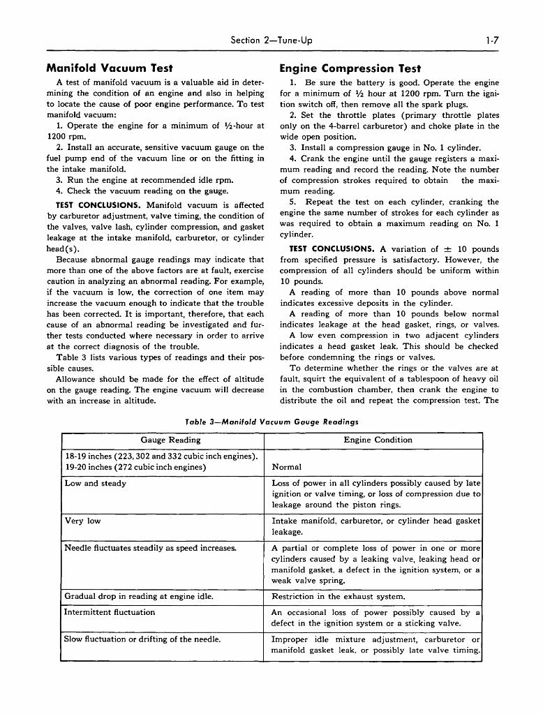
Table 3-Manilold Vacuum Gauge Readings
Gauge Reading Engine Condition
18-19 inches (223,302 and 332 cubic inch engines). 19-20 inches (272 cubic inch engines) Normal
Low and steady Loss of power in all cylinders possibly caused by late ignition or valve timing, or loss of compression due to leakage around the piston rings.
Very low Intake manifold, carburetor, or cylinder head gasket leakage.
Needle fluctuates steadily as speed increases. A partial or complete loss of power in one or more cylinders caused by a leaking valve, leaking head or manifold gasket. a defect in the ignition system, or a weak valve spring.
Gradual drop in reading at engine idle. Restriction in the exhaust system.
Intermittent fluctuation An occasional loss of power possibly caused by a defect in the ignition system or a sticking valve.
Slow fluctuation or drifting of the needle. Improper idle mixture adjustment, carburetor or manifold gasket leak, or possibly late valve timing.
1-8 Chapter I-General Engine Service
oil will temporarily seal leakage past the rings. If ap
proximately the same reading is obtained, the rings are
satisfactory, but the valves are leaking, If the compres
sion has increased 10 pounds or more over the original
reading, there is leakage past the rings.
During a compression test, if the pressure fails to
climb steadily and remains the same during the first
two successive strokes, but climbs higher on the succeed
ing strokes, or fails to climb during the entire test, it
indicates a sticking valve.
Exhaust Gas Analysis An exhaust gas analysis is a method of testing the
ratio of fuel and air entering the cylinders, and the adjustment and performance of the carburetor. HOur ever, it cannot be used to calibrate a carburetor.
As there are various types of analyzers, follow the instructions of the manufacturer. On a dual exhaust system, install the analyzer in the outlet p ipe opposite the side of the system that contains the exhaust gas control valve. For example, if the valve is on the right side, install the analyzer in the left muffler outlet pipe.
3. MANIFOLDS AND EXHAUST GAS CONTROL VALVE
Hot exhaust gases a re diverted into the intake manifold heat riser to provide the heat necessary to vaporize the incoming fuel-air mixture a nd to minimize engine stalling and carburetor icing during cold engine operation.
On the 223 cubic inch engines, a chamber (heat riser) is cast into the intake manifold cente r section between the carburetor and exhaust manifold mounting flanges. A thermostatically controlled va lve, located in the exh aust manifold, directs the exhaust gases into this area.
All 8-cylinder intake manifolds contain a passage through the center section a nd under the carburetor, through which the hot exhaust gases are directed,
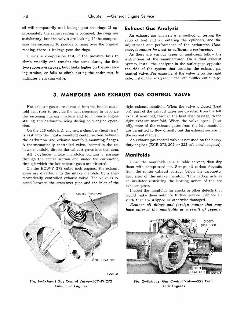
On the ECW-Y 272 cubic inch engines, the exhaust gases are diverted into the intake manifold by a thermostatically controlled exhaust valve. The valve is located between the cross-over pipe and the inlet of the
lOOl-A
Fig, I-E x haust Gas Conlrol Valve-fCY-W 272 Cubic Inch Engin es
right exhaust m a nifold. When the valve is closed (heat on), part of the exhaust gases are diverted from the left
exhaust manifold, through the heat riser passage, to the r ight exhaust manifold. When the va lve opens (heat off), more of the exhaust gases from the left manifold are permitted to flow directly out the exhaust system in the normal manner.
An exhaust gas control valve is not used on the heavy duty engines (ECR 272, 302, or 332 cubic inch engines).
Manifolds Clean the manifo lds In a suitable solvent, then dry
them with compressed air. Scrape all carbon deposits from the center exhaust passage below the carburetor heat riser of the intake manifold. This carbon acts as an insulator restricting the heating action of the hot exhaust gases.
Inspect the m anifolds for cracks or other defects that would make them unfit for further service. Replace all studs that are stripped or otherwise damaged.
R em ove all filings aud Joreign maUer that may have enl.ered I.he mnniJolds a.'i a result of repnirs,
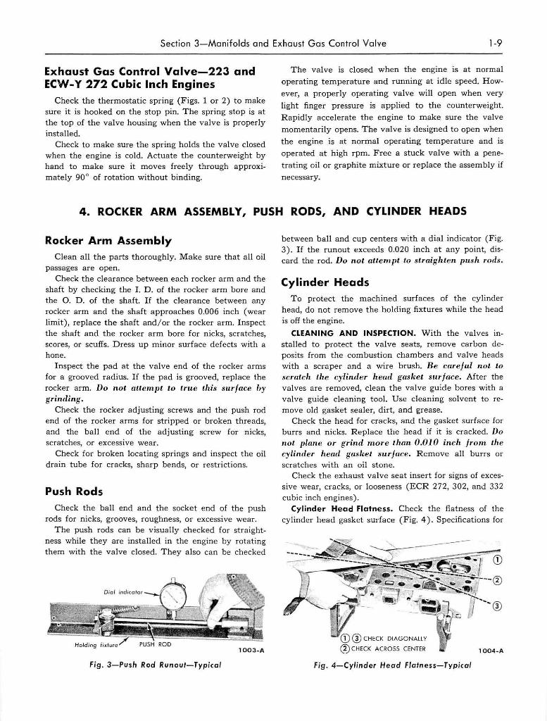
Fig. 2-Exh aust Gas Control Valve-223 Cubic Inch Engines
Section 3-Manifolds and Exhaust Gas Control Valve 1-9
Exhaust Gas Control Valve-223 and ECW-Y 272 Cubic Inch Engines
Check the thermostatic spring (Figs. 1 or 2) to make sure it is hooked on the stop pin. The spring stop is at the top of the valve housing when the valve is properly installed.
Check to make sure the spring holds the valve closed when the engine is cold. Actuate the counterweight by hand to make sure it moves freely through approximately 90 ° of rotation without binding.
The valve is closed when the engine is at normal
operating temperature and running at idle speed. How
ever, a properly operating valve will open when very
light finger pressure is applied to the counterweight.
Rapidly accelerate the engine to make sure the valve
momentarily opens. The valve is designed to open when
the engine is at normal operating temperature and is
operated at high rpm. Free a stuck valve with a pene
trating oil or graphite mixture or replace the assembly if
necessary.
4. ROCKER ARM ASSEMBLY, PUSH RODS, AND CYLINDER HEADS
Rocker Arm Assembly Clean all the parts thoroughly. Make sure that all oil
passages are open. Check the clearance between each rocker arm and the
shaft by checking the I. D. of the rocker arm bore and the O. D. of the shaft. If the clearance between any rocker arm and the shaft approaches 0.006 inch (wear limit), replace the shaft and/or the rocker arm. Inspect the shaft and the rocker arm bore for nicks, scratches, scores, or scuffs. Dress up minor surface defects with a hone.
Inspect the pad at the valve end of the rocker arms for a grooved radius. If the pad is grooved, replace the rocker arm. Do not auem.pt to lrue this slLrface by grinding.
Check the rocker adjusting screws and the push rod end of the rocker arms for stripped or broken threads, and the ball end of the adjusting screw for nicks, scratches, or excessive wear.
Check for broken locating springs and inspect the oil drain tube for cracks, sharp bends, Or restrictions.
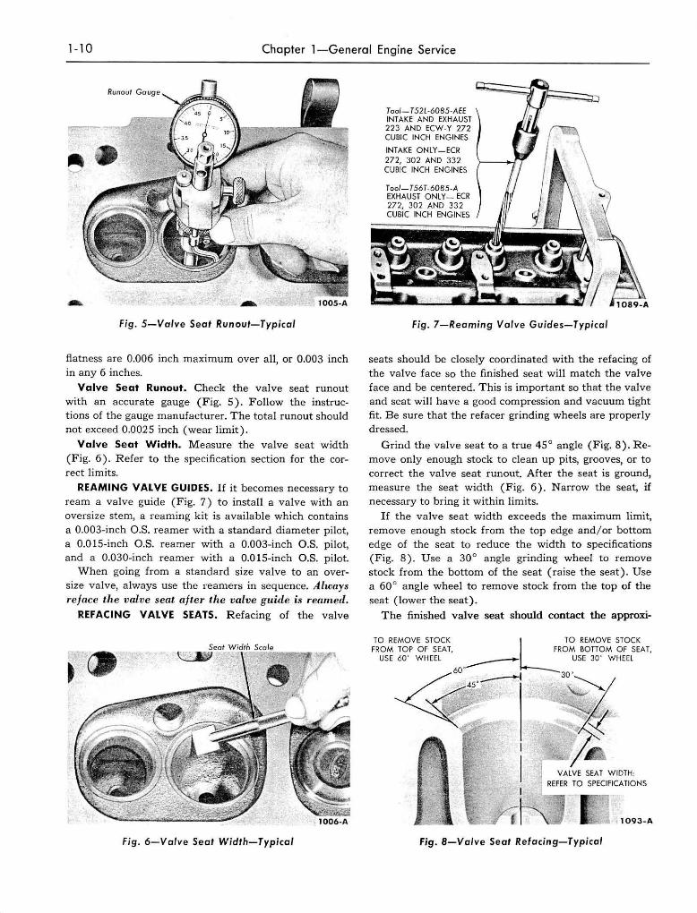
Push Rods Check the ball end and the socket end of the push
rods for nicks, grooves, roughness, or excessive wear. The push rods can be visually checked for straight
ness while they are installed in the engine by rotating them with the valve closed. They also can be checked
Fjg. 3-Push Rod Runout-Typical
between ball and cup centers with a dial indicator (Fig. 3). If the runout exceeds 0.020 inch at any point, discard the rod. Do not atlempt to straighten push rods.
Cylinder Heads To protect the machined surfaces of the cylinder
head, do not remove the holding fixtures while the head is off the engine.
CLEANING AND INSPECTION. With the valves installed to protect the valve seats, remove carbon deposits from the combustion chambers and valve heads with a scraper and a wire brush. Be careful not to scratch the cylinder head gasket surface. After the valves are removed, clean the valve guide bores with a valve guide cleaning tool. Use cleaning solvent to remove old gasket sealer, dirt, and grease.
Check the head for cracks, and the gasket surface for burrs and nicks. Replace the head if it is cracked. Do not plane or grind m.ore than 0.010 inch fro TIt th e cylinder head gasket, surface. Remove all burrs or scratches with an oil stone.
Check the exhaust valve seat insert for signs of excessive wear, cracks, or looseness (ECR 272, 302, and 332 cubic inch engines).
Cylinder Head Flatness. Check the flatness of the cylinder head gasket surface (Fig. 4). Specifications for
'~ ::: -- -;:" -...-------~~---::::' ~--; ~--/~I .".--cD
)" -~PC ~~-;:~~-~"'::. .. j r -® ~1 ' ~ _. ___ ~l_\if "'-----it ·... . . "- 00
CD ® CHECK DIAGONALLY
® CHECK ACROSS CENTER 1004-A
Fig. 4-Cylinder Head Flatness-Typical
1-1 0 Chapter 1-General Engine Service
- - 100S-A
Fig. 5-Valve Seat Runout-Typ;cal
flatness are 0.006 inch maximum over all, or 0.003 inch in any 6 inches.
Valve Seat Runout. Check the valve seat runout with an accurate gauge (Fig. 5). Follow the instructions of the gauge manufacturer. The tota l runout should not exceed 0.0025 inch (wear limit).
Valve Seat Width. Measure the valve seat width (Fig. 6). Refer to the specification section for the correct limits.
REAMING VALVE GUIDES_ If it becomes necessary to ream a valve guide (Fig, 7) to install a va lve with an oversize stern, a reaming kit is available which contains a O.003-inch O.S. reamer with a standard diameter pilot, a O.OIS-inch O.S. reamer with a O.003-inch O.S. pilot, and a O.030-inch reamer with a 0.0 IS-inch O.S. pilot.
When going from a standard size valve to an oversize valve, a lways use the reamers in sequence. Always re face tire v alve seat after the valve guide is reamed.
REFACING VALVE SEATS. Refacing of the valve
Seat ~~.:, -
Fig. 6-Valve Seat Width-Typical
Too/- TS2L-608S -AEE INTAKE AND EXHAUST 223 AND ECW -Y 272 CUBIC INCH ENGINES
INTAKE ONLY -ECR 272, 302 AND 332 CUBIC INCH ENGINES
Tool-TS6 T-60BS-A EXHAUST ONLY _ EeR 272, 302 AND 332 CUBIC INCH ENGINES
Fig. 7-Reaming Valve Guides-Typical
seats should be closely coordinated with the refacing of the valve face so the finished seat will match the valve face and be centered. This is important so that the valve and seat will have a good compression and vacuum tight fit. Be sure that the refacer grinding wheels are properly dressed_
Grind the valve seat to a true 45 ° angle (Fig. 8)_ Remove only enough stock to clean up pits, grooves, or to correct the valve seat run out. After the seat is ground, measure the seat width (Fig. 6). Narrow the seat, if necessary to bring it within limits.
If the valve seat width exceeds the maximum limit, remove enough stock from the top edge and / or bottom edge of the seat to reduce the width to specifications (Fig. 8). Use a 30 0 angle grinding wheel to remove stock from the bottom of the seat (raise the seat). Use a 60 0 angle wheel to remove stock from the top of the seat (lower the seat).
The finished valve seat should contact the approxi-
Fig. 8-Valve Seat Refacing-Typical
Section 4-Rocker Arm Assembly, Pu sh Rods, and Cylinder Heads 1- 11
mate center of the valve face. To determine where the valve seat contacts the face, coat the seat with Prussian blue, then set the valve in place. Rotate the valve with light pressure. If the blue is transferred to the center of the va lve face, the contact is satisfactory. If the blue is transferred to the top edge of the valve face, lower the valve seat. If the blue is transferred to the bottom edge of the valve face, raise the valve seat.
After refacing the valve seat, it is good practice to lightly lap in the valve with a medium grade lapping compound. Remove a ll the compound from the valve and seat a fter the lapping operation.
EXHAUST VALVE SEAT INSERT REPLACEMENT-ECR 272, 302, AND 332 CUBIC INCH ENGINES. To reo
move the valve seat insert, invert t he head and position a drift in the exhaust valve port, then drive the insert out.
Counterbore the insert recess to specifications (Fig. 9). Cut slightly below the o ld counterbore depth to clean up this face (approximately 0.001-0.002 inch) . Clean out chips and oil from the recess.
Chill the oversize insert and the insta llation tool in dry ice for lj2 hour. The insert must be installed im· m.ediately upon rem.oval from the dry ice. Protect the hands when Iwndling the chilled ill sert ami tool. Position the insert on the tool with the small r adius on the outer edge facing outward. P ilot the driving tool in the valve guide, then drive the insert into the counterbore unt il i:)is fully seated. Do not peen the area around the insert. Reface the new insert.
WATER OUTlET CONNECTION - 8·CYLINDER ENGINES. The cylinder heads on each particular engine are interchangeable.
To cha nge the heads from one bank to another on a 272 cubic inch engine, it is necessary t hat a pl ug be installed in the water outlet at the rear of the right head and a water temperature sending unit adapter is insta lled in the water opening at the rear of the left head.
To change the heads from one bank to another on a 302 or 332 cubic inch engine, it is necessary to remove
COUNTERBORE TO ENGINE SPECIFICATIONS
':::";:::j'--:-------i-;:;,;:;;::.'- EXHAUST
TRUE UP THIS FACE liGHTlY
VALVE PORT
1210· A
Fig . 9-Counterbore For Oversize Insert-fCR 2721 302 , and 332 Cubic Inch Engine s
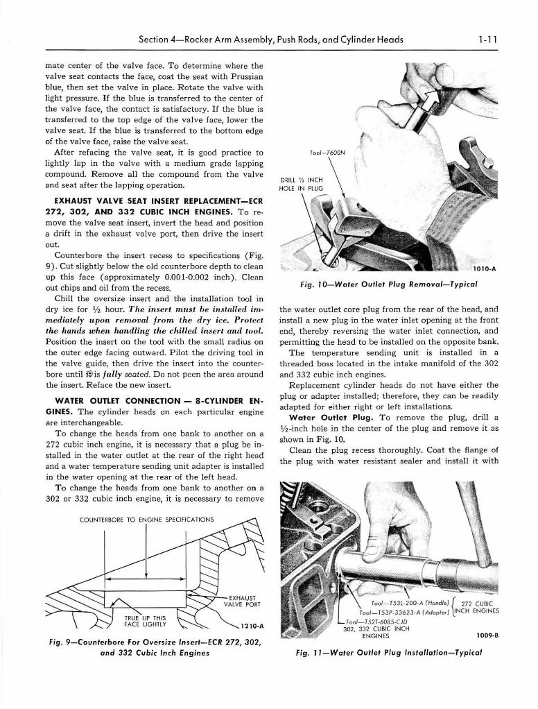
Fig. r O-Wafer Ou"ef Plug Removal-Typical
the water outlet core p lug from t he rear of the head, and insta ll a new plug in the water inlet opening at the front end, thereby reversing the water inlet connection, and permitting the head to be installed on the opposite bank.
The temperature sending unit is installed in a threaded boss located in the intake manifold of the 302 and 332 cubic inch engines.
R eplacement cylinder heads do not have either the plug or adapter installed; therefore, they can be readily adapted for either right or left insta llations.
Woter Outlet Plug. To remove t he plug, drill a lj2 -inch hole in the center of the plug and remove it as shown in Fig. 10.
Clean the plug recess t horou ghly. Coat the flange of the plug with water resistan t sealer and install it with
Too/ - T53l ·200·A (Hood/e) r 272 CUBIC
Too/-T53P-33623 .A (Adopter) ~NCH ENGINES
T ool- T52T·6085-CJO 302, 332 CUBIC INCH
ENGINES 1009·8
Fig. J 1-Water OUflet Plug Installafion-Typical
1- 1 2 Chapter 1-General En gin e Service
INSTAll TOOl INTO ADAPTER
Tool- Tsor ·IDOA
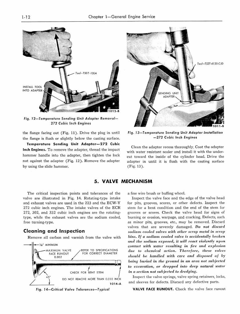
Fig . 12-Temperature Sending Un it Adapter Remova/-
272 Cubic Inch Engin es
the flange facing out (Fig. 11) . Drive the plug in until
the flange is flush or slightly below the casting surface.
Temperature Send ing Unit Adapter-272 Cubic
Inch Engines. To remove the adapter, thread the impact
hammer handle into the adapter, then tighten the lock
nut against the adapter (Fig, 12). Remove the adapter
by using the slide hammer.
Too/-T52T-6135-CJD
Fig. J 3-Temperature Sending Unit Adapter Installation -272 Cubic Inch Engin es
Clean the adapter recess thoroughly. Coat the adapter with water resistant sea ler and insta ll it with the undercut toward the inside of the cylinder head. Drive the
adapte r in until it is fl u sh with the casting surface
(Fig. 13).
5. VALVE MECHANISM
The critical inspection points and tolerances of the
valve are illustrated in Fig. 14. Rotating-type intake
and exhaust valves a re used in the 223 and the ECW-Y 272 cubic inch engines. The intake valves of the ECR 272, 302, and 332 cubic inch en gines are the rotatingtype, while the exhaust valves a re the sodium cooled,
free turning-type.
Cleaning and Inspection Remove a ll carbon and varnish from the valve with
MINIMUM
"", _ _ MAXIMUM VALVE FACE RUNOU T
0.002
REFER TO SPECIFICATIONS FO R CORRECT DIAMETER
f CHECK FOR BENT STEM l
DO NOT REMOVE MORE THAN 0.0 I 0 INCH
1014-A
fjg . 14-Crit;cal Valv e Tol era nces-Typical
a fine wire brush or buffing whee1. Inspect the va lve face and the edge of the valve head
for pits, grooves, scores, or other defects. Inspect the stem for a bent condition an d the end of the stem for grooves or scores. Check the valve head for signs of
burning or erosion, warpage, and cracking. D efec ts, such as minor pits, grooves, etc., may be removed. Discard
va lves that are severely damaged. Do not d iscard sodium cooled va/ve ... wi lh oth er scrap m elni in seral} bins. If n sodiu.m. (;ooletl valve is (lCcirienLally IJrolwn a",l th e sodium exposed, it will r eact v iolently u.pon con/at;l. w ilh water resu.lting in. fir e nrul ex plosion du e to chemical act io 1l. T h ere fore, these 'vldlH:S
shou ld be handled with care (Ind disposed oj hy
beill g bu.ried in I.h e ground in an area not subjected
to excavlltion, or (hopped into d eep natural water
in (l sec/.ion flat sulJjeded to dredgill g. Inspect the va lve springs, valve spring retainers, locks,
and sleeves for defects. Discard any defective parts.
VALVE FACE RUNOUT. Check the valve face runout
Section 5 - Va lve Mechan ism 1 -1 3
(Fig. 15). The wea r limit for runout is 0 .002 inch tota l indicator reading.
VALVE STEM CLEARANCE. Check the va lve stem to va lve guide clearance of each valve in its respective valve guide with the tool shown in Fig. 16 or its equivalent.
Install t he tool on t he va lve s tem until fully seated and ti ghten the set screw, t hen permit the va lve to drop away from its seat unti l t he tool contac ts the upper surface of the valve guide. P osition a dial ind ica tor with a fiat tip against the center portion of the sphe rical section of the tool at a pproximate ly 90° to the va lve ste m. Move the tool back a nd fo rth on a p lane tha t para ll els normal rocker action and t ake the indica to r reading wit hout lifting the tool from the valve guide upper surface. Divide the ind ica tor reading by 2 (divis ion factor of the tool) to obtain the actual stem cleara nce.
The wear limit for inta ke valve st em clearance is 0.0045 inch. The wea r limit for the exhaust va lve stem clearance is 0.0065 inch (223 a nd ECW·Y 272 cubic inch engines) o r 0.0055 inch ( ECR 272, 302, a nd 332 cubic inch engines. If the clea ra nce a pproaches the wear limit, try a new valve.
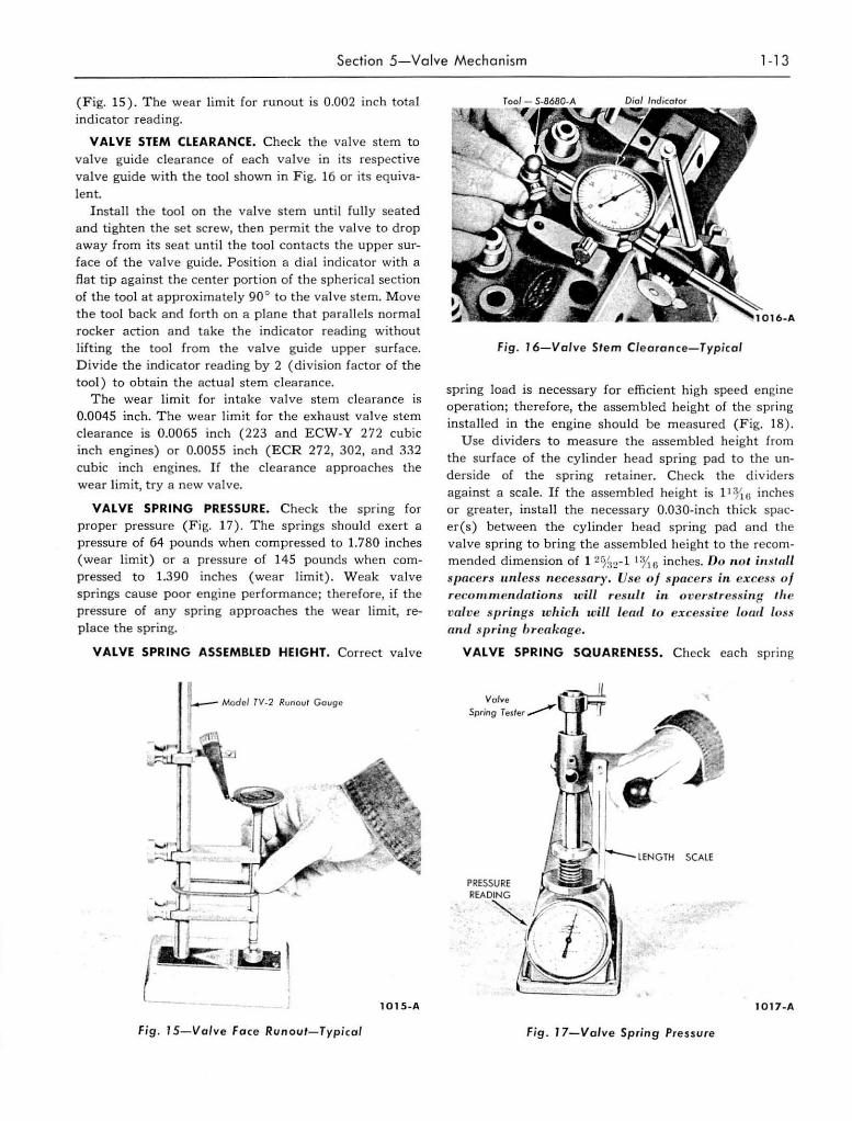
VALVE SPRING PRESSURE. Check the spring for proper pressure (Fi g. 17). The springs should exert a pressure of 64 pounds when compressed to 1.780 inches (wear limit) or a pressure of 145 pounds when compressed to 1.390 inches (wear limit ). Weak va lve spr ings cause poor engine performa nce; therefore, if the pressure of any spring approaches t he wear lim it, replace the spring.
VALVE SPRING ASSEMBLED HEIGHT. Correct valve
Model TV·2 RtJnoul Gouge
lOlS- A
Fig . J 5-Valve Face Runout- Typ ical
6-A
Fig . 16-Valve St e m Clearance-Typical
spring load is necessary for effici ent high speed e ngine operation; therefore, the assembled height of the spring insta lled in the engine should be m easured (Fig. 18) .
U se dividers to measure the assembled he ight from the surface of the cyJinder head spring pad t o the unde rside of the spring reta iner. Check the div ide rs aga inst a scale. If t he assembled height is ] 1:yl{j inches or greater, inst a ll the necessary O.030-inch th ick spacer(s ) between the cylinder head spring pad a nd the va lve spring to bring the assembled height to the recommended dimension of 1 2%2-1 111 G inches. Do 1I 0l ill Mall spacers unless necessary. Use of Sp flcers in. ex cess oj recOlnm elltialio lls will re.'HI./t ill o versl.ressill f! 'lte ·valve springs w hich will lead Lo excessive lowl loss alit! .~pritlg breakage .
VALVE SPRING SQUARENESS. Check each spring
I017- A
Fig . '7-Valve Spring Pres ~ ure
1-14 Chapter 1-Ge ne ral Eng in e Se rvice
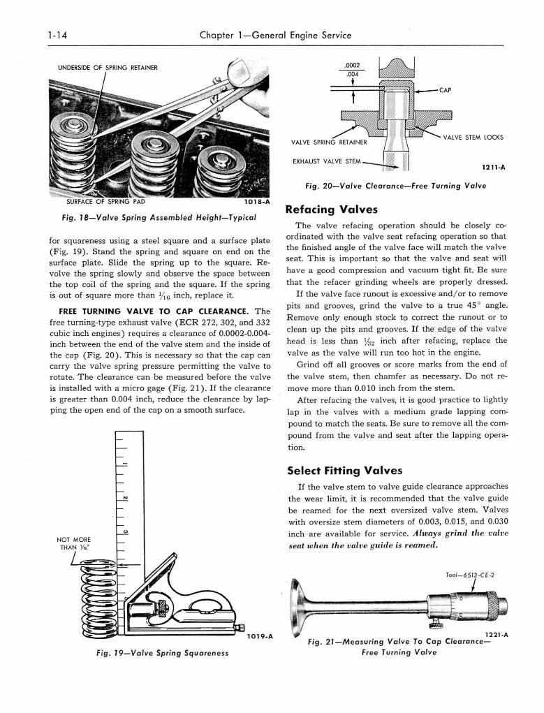
fjg . JS-Val ve Spring As sembled He ight-T ypical
for squareness using a steel square a nd a surface plate (Fig. 19) . Stand the spring and square on end on the surface plate. Slide the spring up to the square. R evolve the spring slowly and observe the space between the top coi l of the spring and the square. If the spring is out of square more than lit 6 inch, replace it.
FREE TURNING VALVE TO CAP CLEARANCE. T he free turning-type exhaust valve (ECR 272, 302, and 332 cubic inch engines) requires a clearance of 0.0002-0.004-inch between the end o f the va lve stem and the inside of the cap (Fig. 20) . T h is is necessary so tha t t he cap can carry the valve spring pressure permitt ing the va lve to rotate. The clearance can be measured before the valve
is inst a lled with a micro gage (Fig. 21). If the clearance is greater than 0.004 inch , reduce the clearance by lapping the open end of the cap on a smooth surface.
Fig . 19- Valve Spring Square ness
VALVE VALVE STeM LOCKS
EXHAUST VALVE '''.M .--w:..L Ull ·A
Fig. 20-Valve Cle aran ce-Free Turning Val ve
Refacing Valves The va lve refacing opera tion should be closely co
ordinated with t he va lve seat refacing operation so that the finished angle o f the va lve face wi ll match the valve sea t. This is important so tha t t he valve a nd seat wi ll
have a good compression and vacuum tight fit. B e sure
t ha t the refacer grinding wheels are properly dressed.
If the va lve face runout is excessive and / or to remove
pits and grooves, grind the valve to a true 45 ° angle.
R emove only enough stock to correct the run out or to
clean up the pits and grooves. If the edge o f the valve
head is less than Y:~2 inch a fter refacing, replace the
va lve as the valve will run too hot in the engine.
Grind off a ll grooves or score marks from the end of
the valve stem, then chamfer as necessary. Do not re
move more than 0.0 10 inch from the stem.
After refacing the va lves, it is good practice to lightly
lap in t he valves w ith a medium grade lapping com
pound to match t he seats. Be sure to rem ove a ll the com
pound from the va lve a nd seat a fter the lapp ing opera
tion.
Select Fitting Valves If the va lve stem to valve guide clea rance approaches
the wear limit, it is recommended that t he va lve guide
be reamed for the next oversized valve stern. V a lves
with oversize stem diameters of 0.003, 0.0 15, and 0.030 inch are avai lable for service. A lways grind th e val vc
sea l whclI I.he 'valve gu ide is reamed.
U ll ·A Fi g . 2 J -Me asuring Val ve To Cap Cle a ran ce-
Free Tu rnin g Valv e
Section 5-Valve Mechan ism 1 -1 5
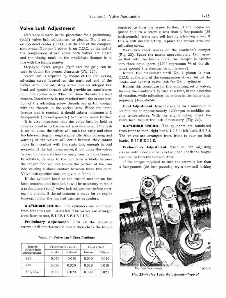
Valve Lash Adjustment
R eference is made in the procedure for a preliminary (cold) valve lash ad justment to placing N o. 1 piston on top dead center (T.n.C.) at the end of the compression stroke. Number 1 piston is on T.n.C. at the end of the compression stroke when both valves are closed and the timing mark on the crankshaft damper is in line with the timing pointer.
Step-type feeler gauges (lego" and "no go") can be used to obtain the proper clearance (Fig. 22).
V alve lash is adjusted by means of the self locking adjusting screw located on the push rod e nd of the rocker arm. The adjusting screw has an integral hex head and special threads which provide a n interference fit in the rocker arm. The first three t hreads are lead threads. Interference is not reached until the center portion of the ad justing screw threads are in full contact with the threads in the rocker arm. When the interference area is reached, it should take a minimum of 3 foot-pounds (36 inch-pounds) to turn the screw furth er.
It is very important that the valve lash be held as close as poss ible to the correct specifications. If the lash is set too close, the valves will open too early and close too late resulting in rough engine idle. Also, burning and warping of the valves will occur because they ca nnot make firm contact with the seats long enough to cool
properly. If the lash is excessive, it will cause t he va lves
to open too late a nd close too early causing valve bounce.
In addition, damage to the cam lobe is likely because
the tappet foot will not fo llow the pattern of the cam
lobe causing a shock contact between these two parts.
Va lve lash specifications are given in T able 4.
If the cylinder head or the rocker mecha nism has
been removed a nd installed, it will be necessary to make
a preliminary (cold) valve lash adjustment before start
ing the engine. If the adjustment is made for an engine
tune-up, follow the final adjustment procedure.
6-CYLINDER ENGINE. The cylinders are numbered
from front to rear , 1-2-3-4-5-6. The valves a re arranged
from front to rear, E-I-I-E-I-E -E-I-E-I-I-E.
Preliminary Adjustment. T urn all the adjusting
screws until interference is noted, then check the torque
Ta ble 4- Valve Lash Specification s
E ngine P rel imi nary ( Cold) Final (Hot) (Cub ic I nch
Dis placement ) Intake Exhaust Intake Exhaust
223 0.0 19 0.019 0.019 0.01 9
272 0.020 0.020 0.01 9 0.01 9
302,332 0.009 0.02 3 0.009 0.021
required to turn the screw furth er. If the torque required to turn a screw is less t ha n 3 foot-pounds (36 inch~pounds), try a new self locking adjust ing screw. If this is sti1l unsatisfactory, replace t he rocker a rm and adjusting screw.
Make two chalk marks on the crankshaft d8mper (Fig. 23) . Space the marks approximately 120 0 apart so that with the timing mark, the damper is divided into three equal parts ( 120 0 represents % of the distance around the da mper circumference).
Rotate the crankshaft until No. 1 piston 1S near T.D.C. at the end of the compression stroke. Adjust the intake a nd exhaust valve lash for No. 1 cylinder.
R epeat this procedure for the remaining set o f va lves, turning the crankshaft 1/3 turn at a t ime, in the direction of rotat"ion, while adjusting the va lves in the firin g order sequence (1-5-3-6-2-4).
Final Adjustme nt. Run the engine for a mi nimum of 30 minutes at approximately 1200 rpm to stabilize en~ gine temperatures. W ith the engine idling, check the va lve lash. Adjust t he lash if necessary (Fig. 22).
S-CYLINDER ENGINE. The cylinders are numbered
from front to rear- right bank, 1-2-3-4; left bank, 5-6-7-8. T he va lves are arranged from front to rear on both
banks, E-I-I-E -E-I-I-E.
Preli minary Adjustme nt. Turn a ll the adjusting
screws until interference is noted, then check t he t orque
required to tUrn the screw fu rther. If the torque required to tu rn the screw is less than
3 foot-pounds (36 inch-pounds), try a new self locking
Fig. 22-Valve Lash Adjustment- Typical
1-16 Chapter 1-General Engine Service
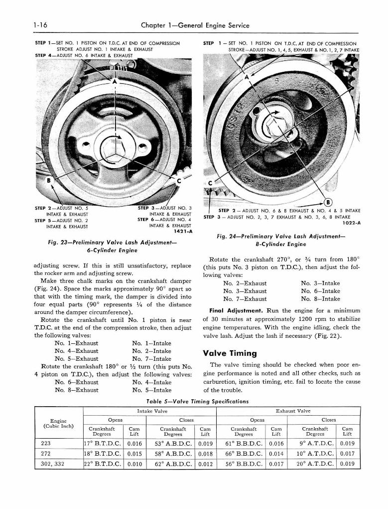
STEP l -SET NO. 1 PISTON ON LD.C. AT END OF COMPRESSION STROKE ADJUST NO. l iNT AKE & EXHAUST
STEP 4 _ADJUST NO. 6 INTAKE & EXHAUST
INTAKE & EXHAUST
STEP 5 -ADJUST NO. 2 INTAKE & EXHAUST
INTAKE & EXHAUST STEP 6 _ADJUST NO . .4
INTAKE & EXHAUST
1421·A
Fig. 23-Preliminary Valve Lash Adjustment-6-Cylinder Engine
adjusting screw. If this is st ill unsat isfactory, replace the rocker arm a nd adjusting screw.
Make three chalk m arks on the crankshaft damper (Fig. 24). Space the marks approximately 90° apart so that with the timing mark, the da mpe r is divided into four equal parts (90 0 represents 1f4 of the distance around the damper circumference).
Rotate the cranksha ft until No. 1 piston is near T.n,C. at the end of the compression stroke, then adjust the following valves:
No. I-Exhaust No.4- E xhaust No.5- Exhaust
No. 1- Intake No.2- Intake No.7- Intake
Rotate the crankshaft 180° or 1f2 tUrn (this puts No. 4 piston on T .n .c.) , then adjust the following valves:
No. 6-Exhaust No.4- Intake No.8-Exhaust No.5- Intake
STEP 1 - SET NO. 1 PISTON ON T.D.C. AT END O F COMPRESS ION
STEP :2 - ADJUST NO.6 & 8 EXHAUST & NO.4 & 5 INTAKE
STEP 3 - ADJ UST NO.2, 3, 7 EXHAUST & NO.3, 6, 8 INTAKE 1022-A
Fig. 24-Pre/iminary Valve lash AdjustmentS-Cylinder Engine
R otate the crankshaft 270°, or % turn from 1800
(this puts No.3 piston on T .n.C.) , then adjust the following valves:
No.2- Exhaust No.3 - Exhaust N o.7-E xhaust
No.3- Intake No.6-Intake No.8- Intake
Final Adjustment. Run the engine for a minimum
of 30 minutes at approximate ly 1200 rpm to stabi lize
engine temperatures. With t he engine id ling, check the
va lve lash. Adjust the lash if necessary (Fig. 22).
Valve Timing The va lve timing should be checked when poor en
gine performance is noted and a ll other checks, such as
carburetion, ignition timing, etc. fail to locate the cause
of the trouble.
Table 5-Valve Timing Specifications
Intake Vnlve Exhaust Valve
E ngine Opens Closes Opens Closes (Cubic Inch) Cranksha ft Cam Crankshaft Cam Crankshaft Cam Crankshaft Cam
Degrees L ift D egrees Lift D egrees Lift Degrees L ift
223 17° B .T.D .C . 0.016 53° A.B. D.C. 0.019 61 ° B.B.D.C. 0.0 16 9° A.T.D.C. 0.019
272 18° B.T.D.C. 0.015 58° A .B . D.C. 0.018 66° B.B.D.C. 0.01 4 10° A .T.D.C. 0.017
302, 332 22 ° B.T.D.C . 0.010 62 ° A.B.D.C. 0.0 12 56° B.B.D.C . 0.017 20° A.T.D .C. 0.019
Section 5-Valve Mechan ism 1-17
Before the valve timing is checked, check for a bent timing pointer. Bring the No. 1 piston to T .D.C. on the compression stroke and see if the timing pointer is aligned with the T.n.C. mark on the damper.
If the va lve timing is not within specifications, check the timing chain, camshaft sprocket or gear, c rankshaft sprocket or gear, camshaft, and crankshaft in the order of accessibility.
To check the valve timing with the engine installed in the truck, proceed as fo llows :
Install a quadrant on the crankshaft damper. Back off the No. 1 intake va lve adjusting screw, then sl ide the rocker arm assembly to one side and secure it in this position. Make sure the push rod is in the t appet
socket, then install a dial indicator in such a manner as to have the actuating point of the indica tor in the push rod socket and in the same plane as the push rod movement (Fig. 29). T urn the crankshaft damper s lowly in the d irection of rotation until the tappet is on the heel of the cam lobe. At this point the push rod wi ll be in its lowest position. Zero t he dial indicator and continue turning the crankshaft s lowly in the direction of rotation until the dial indicator registers the specified camshaft lobe lift (Table 5).
Compare the crankshaft degrees indicated on t he quadrant with specifications (Table 5) . After the va lve opening is checked, continue to rotate the engine to check the valve closing.
6. TIMING CHAIN, TIMING GEARS, CAMSHAFT, AND BEARINGS
Timing Chain-223 and 272 Cubic Inch Engines
CLEANING AND INSPECTION. Clean all parts in solvent and dry them with compressed air. Inspect the chain for broken links and the sprockets for cracks,
worn or d amaged teeth. It is recommended that all the
components be replaced if anyone item needs replace
ment.
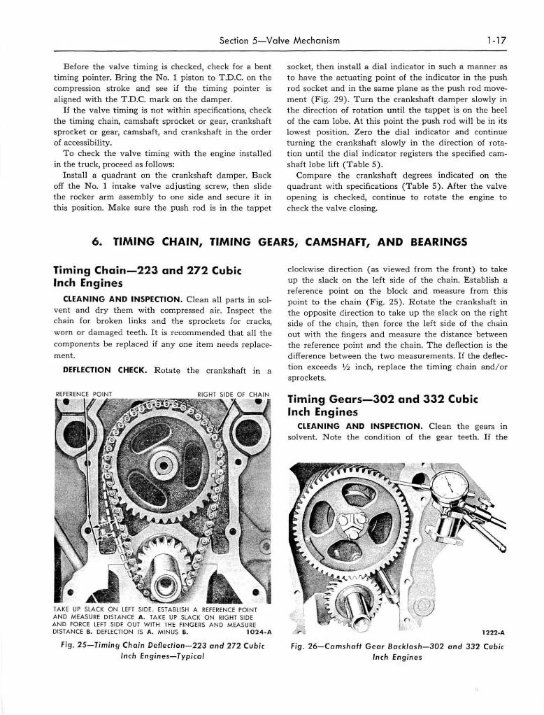
DEFLECTION CHECK. Rotate the crankshaft in a
REfERENCE POINT RIGHT SIDE Of CHAIN
• •
TAKE UP SLACK ON LEFT SIDE. ESTABLISH A REFERENCE POINT AND MEASURE DISTAN CE A . TAKE UP SLACK ON RIGHT SIDE AND FORCE LEFT SIDE O UT WITH THE fiNGE RS AND MEASURE DI STANCE B. DEfLECTION IS A . MINUS B. 102 4 -A
Fig. 2S-Timing Chain De Oection-223 a nd 2 72 Cu bic In ch En gin es-Typical
clockwise direction (as viewed from the front) to take up the slack on the left side of the chain. Establish a reference point on the block and measure from this point to the chain (Fig. 25) . Rotate the crankshaft in the opposite direction to take up the s lack on the right side of the chain, then force the left side of the chain out with the fingers and measure the distance between the reference point and the chain. T he deflection is the difference between the two measurements. If the deflection exceeds 1/2 inch, replace the timing chain and/or sprockets.
Timing Gears-302 and 332 Cubic Inch Engines
CLEANING AND INSPECTION . C lean the gears In
solvent. Note the condition of the gear teeth . If the
Fig. 26-Cams h a ft Ge ar Backla sh-302 and 332 Cubic Inch En gines
I· 18 Chapte r I-General Engi ne Service
/
1234-A
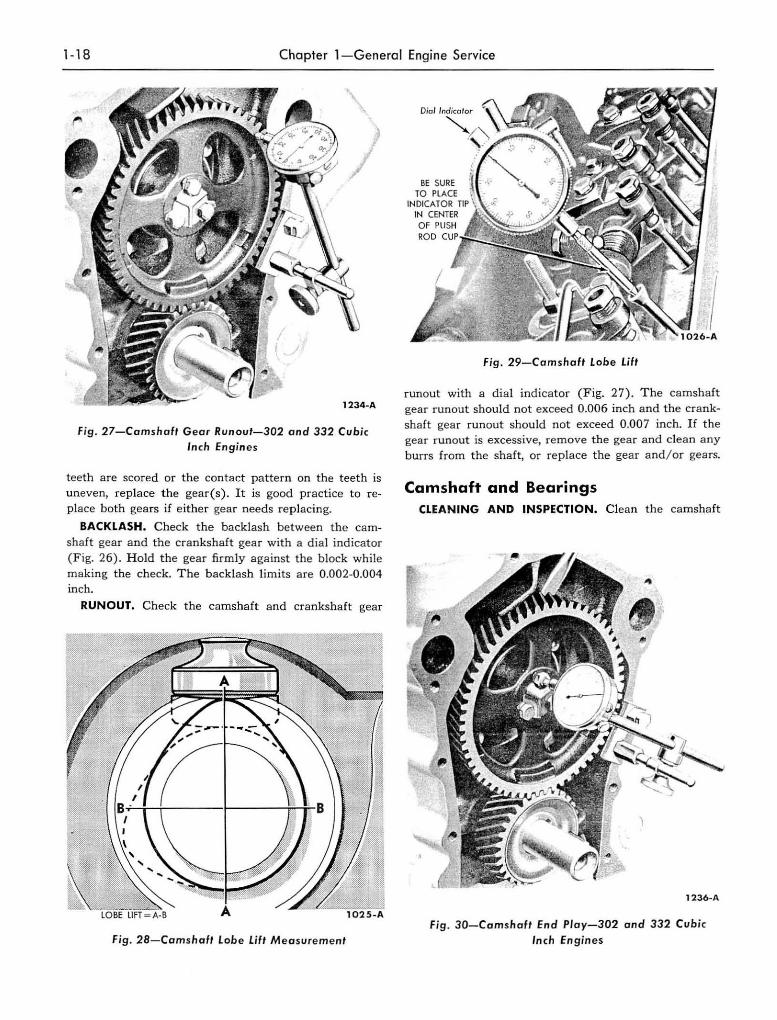
Fig . 27-Camshoft Gear Runoul-302 and 332 Cubic Inch Engines
teeth are scored or the contact pattern on the teeth is uneven, replace the gear(s) . It is good practice to replace both gears if either gear needs replacing.
BACKLASH. Check the backlash between the cam· shaft gear and the crankshaft gear with a dia l indicator (Fig. 26) . H old the gear firmly against the block while making the check. The backlash limits are 0.002-0.004 inch.
RUNOUT. Check the camshaft a nd crankshaft gear
fig . 28-Comshalt Lobe Lift Measurement
BE SURE TO PLACE
INDICATOR TIP IN CENTER OF PUSH ROD CUP"::i!!". ::i!
Fig. 29-Camshaft Lobe Lift
runa ut with a dial indicator (Fig. 27) . The camshaft gear funaut should not exceed 0 .006 inch and the crankshaft gear runaut should not exceed 0 .007 inch. If the gear runout is excessive, remove the gear and clean any burrs from the shaft, or replace the gear and/ or gears.
Camshaft and Bearings CLEANING AND INSPECTION. Clean the camshaft
1236-A
Fig . 30-Camshaft End P/ay-302 and 332 Cubic Inch Engin es
Section 6-Timing Chain , Timing Gears, Camshaft, and Bearings 1-19
in solvent and wipe dry. Inspect t he camshaft lobes for pitting, scoring, and signs of abnorma l wear. Lobe wear characteristics may result in pitting in the general area of t he nose portion of the lobe. This pitt ing is not detrimenta l t o the operation of the camshaft, therefore, it should not be replaced unti l the lobe lift loss has exceeded 0.005 inch. The li ft of suspected worn lobes should be checked by measuring over the top of the lobe with a micrometer and subtracting the measurement of the base circle diameter (Fig. 28).
Check the camshaft journal to bearing clearances by measuring the d iameter of the journals and the 1.0. of the bearings. The bearing clearance wear limit is 0.006 inch. If the clearance approaches the wear limit, the camshaft journa ls should be ground for undersize bear~ ings or the camshaft replaced, and / or t he bearings should be replaced. Bearings are availa ble pre-fi nished to size for standard and undersize journa l diameters. Check the parts catalog for the undersizes available.
Check the distributor d rive gear for broken or chipped teeth.
Remove light scuffs, scores, or nicks from the cam~
shaft machined surfaces with a smooth oi lstone.
CAMSHAFT LOBE LIFT (CAMSHAFT INSTALLED). This procedure is similar to the procedure for checking va lve timing. Loosen the valve rocker arm adjusting screw,
then slide the rocker arm assembly t o one side and secure it in this position. M ake sure the push rod is in the tappet socket, then insta ll a dia l indicator in such a manner as to have the actuat ing point of the indicator in the push rod socket a nd in the same plane as the push rod movement (Fig. 29). Turn the crankshaft damper slowly in the d irection of rotation until the tappet is on the heel of the cam lobe. At this point the push rod will be in its lowest position. Set the d ia l indicator on zero, then continue t o rotate the damper slowly until the push rod is in the fully raised position. Compare the total lift recorded on the indicator with specifications. Continue to rotate the engine until the indicator reads zero. This later step is a check on the accuracy of the original indicator reading.
CAMSHAFT END PLAY-302 AND 332 CUBIC INCH
ENGINES. Push the camshaft toward the rear of the
engine. Place a dial indicator point against a suitable
surface on the front end of the camshaft assembly (Fig.
30). Set the dial on zero, then pull the camshaft forward and release it. Compare the dia l reading with
specifications. The end play wear limit is 0.012 inch.
If the end play is excessive, check the spacer for cor
rect insta llation. Replace the thrust p la te and/or spacer
if necessary.
7. CRANKSHAFT AND MAIN BEARINGS
The crankshaft is supported by five main bearings in 8-cylinder engines and by four main bearings in 6-cylinder engines. Crankshaft end play in a11 engines IS controlled by the No.3 main bearing flanges .
Crankshaft Handle the crankshaft wit,1t care to avoid possible
fractures or damage to the finished surfaces.
CLEANING AND INSPECTION. Clean the crankshaft with solvent, then blowout all oil passages with compressed air.
Inspect main and connecting rod journals for cracks, scrat ches, grooves, or scores. Dress m inor imperfections with an oi lstone. R egrind severely marred journals.
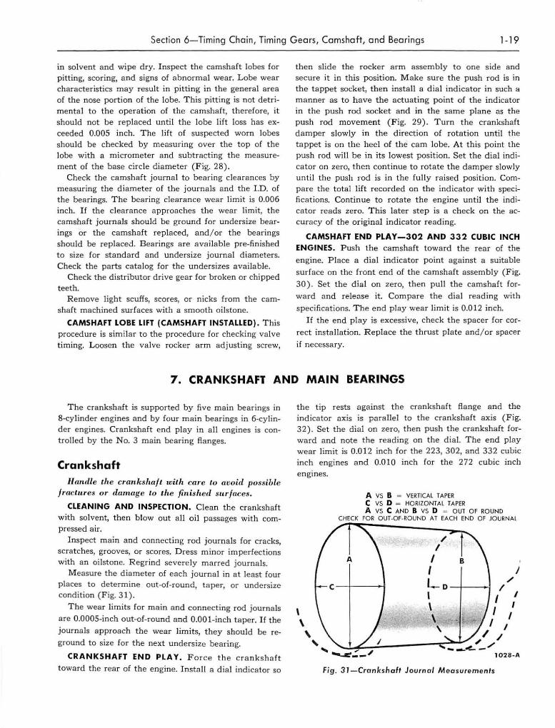
Measure the diameter of each journal in at least four places to determine out-of-round, taper, or undersize condition (F ig. 31).
The wear limits for ma in and connecting rod journals are O.OOOS-inch out-of-round and O.OOl-inch t aper. If the
journals approach the wear limits, they should be re
ground to size for the next undersize bearing.
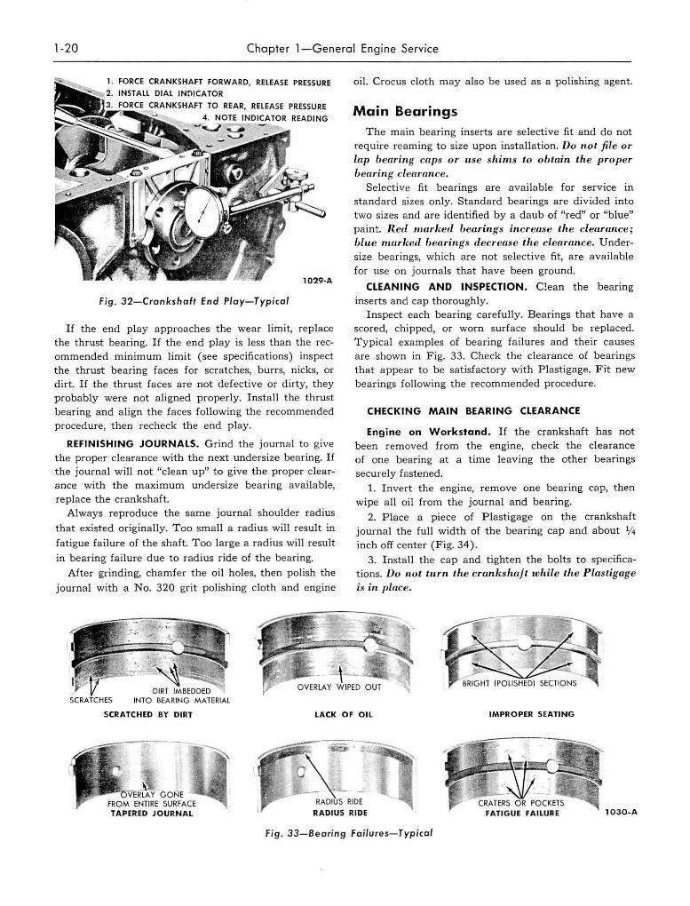
CRANKSHAFT END PLAY. F orce the cra nkshaft toward the rear of the engine. Insta ll a dial indicator so
the tip rests against the crankshaft flange and the indicator axis is parallel to the crankshaft axis (Fig. 32). Set the d ial on zero, then push the crankshaft forward and note the reading on the dial. The end play wear limit is 0.012 inch for the 223, 302, and 332 cubic inch engines a nd 0.010 inch for the 272 cubic inch engines.
\ \ , ,
A vs B "" VERTICAL TAPER C VS D = HORIZONTAL TAPER A VS C AND B VS 0 .... OUT OF ROUND
CHECK fO R OUT·Of·ROUND AT EACH END OF JOURNAL
A
/
'~.:_/ 102B-A
Fig . 31-Crankshaf' Journal M easurements
1-20 Chapler 1-General Engine Service
FORCE CRANKSHAFT FORWARD, RElEASE PRESSURE INSTALL DIAL IN~ICATOR
CRANKSHAFT TO REAR, RElEASE PRESSURE
l029-A
Fig. 32-Crankshaft End Play-Typical
If the end play approaches the wear limit, replace the thrust bearing. If the end play is less than the recommended minimum limit (see specifications) inspect the thrust bearing faces for scratches, burrs, nicks, or dirt. If the thrust faces are not defective or dirty, they probably were not a li gned prope rly. Insta ll the thrust bearing and align the faces following the recommended procedure, then recheck the end play.
REFINISHING JOURNALS. Grind the journal to give the proper clearance with the next undersize bearing. If the journal will not uc1ean up" to give the proper clearance with the maximum undersize bearing available, replace the crankshaft.
Always reproduce the same journal shoulder radius
that existed originally. Too small a radius will resu lt in
fatigue failure of the shaft. Too large a radius will result
in bearing failure due to radius ride of the bearing.
After grinding, chamfer the oil holes, then polish the
journal with a No. 320 grit polishing cloth and engine
oil. Crocus cloth may also be used as a polishing agent.
Main Bearings
The main bearing inserts are selective fit and do not require reaming to size upon installa tion. Do not file or lap bearing caps or use shinls Lo oblain the proper bearing clearance.
Selective fit bearings are available for service in standard sizes only. Standard bearings are divided into two sizes and are identified by a daub of "red" or "blue" paint. RetL Ilwdwd bellrings increllse Lire clearance; Mue 1nllrhetl 11carings decren,'!e the clellrllnce. Under
size bearings, which are not selective fit, are available for use on journals that have been ground.
CLEANING AND INSPECTION. C!ean the bearing inserts and cap thoroughly.
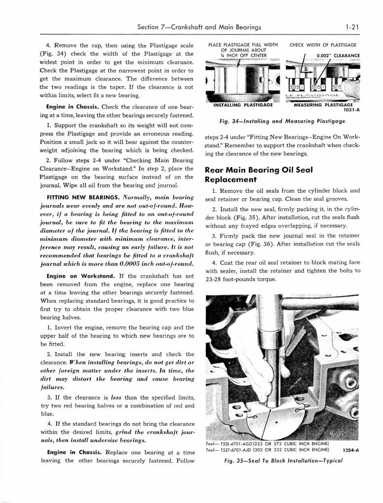
Inspect each bearing carefully. Bearings that have a scored, chipped, or worn surface should be replaced. Typical examples of bearing failures and their causes are shown in Fig, 33. Check the clearance of bearings that appear to be satisfactory with Plastigage. Fit new bearings following the recommended procedure.
CHECKING MAIN BEARING CLEARANCE
Engine on Workstand. If the crankshaft has not been removed from the engine, check the clearance of one bearing at a time leaving the other bearings securely fastened.
1. Invert the engine, remove one bearing cap, then wipe all oil from the journal and bearing.
2. Place a piece of Plastigage on the crankshaft journal the full width of the bearing cap and about V4 inch off center (Fig. 34).
3. Install the cap and tighten the bolts to specifications. Du nuL turn I,/ie crankshafl while lhe Plasligage is in place.
SCRATCHED BY DIRT LACK OF OIL IMPROPER SEATING
RADIUS RIDE 1030-A
Fig . 33-Beoring Failures-Typical
Section 7-Cronkshaft and Main Bearings 1-2 1
4. Remove the cap, then using t he Plastigage scale
(Fig. 34) check the width of the Plast igage a t the
widest point in order to get the minimum clearance.
Check the Plastigage at the narrowest point in order to
get the maximum clearance. The difference between
the t wo readings is the ta per. If the clearance is not
within limits, se lect fit a new bearing.
Engine in Chassis. Check the clearance of onc bear
ing at a time, leaving the other bearings securely fastened.
1. Support the crankshaft so its weight will not com
press the Plastigage and provide a n erroneous reading.
Position a small jack so it wi ll bea r against the counter
weight adjoining the bearing which is being checked.
2. Follow steps 2-4 under "Checking M ain Bearing
Clearance- Engine on W orkstand." In step 2, p lace the
Plastigage on the bearing surface instead of on the
journal. Wipe all oi l from the bearing and journal.
FITTING NEW BEARINGS. Normally, main bearing journals wcar evenly and are not oU/-of-round. How .. ever, if a bcaring is being fiue(l 10 all out-oj-round
journal , be sure to fit the bearing to th e nwximum diameter of the jourual. If the beariug is fitted to fh e minimum. diameter with tninimum. clearallce, inler
j erence mny result , causing an enriy jnillLre . It is not reco mmended that IJearings be fitl.e(l to a crankshaft journal which is more tlran 0.0005 inch out-of-round.
Engine on Workstand . If the crankshaft has not
been removed from the engine, replace one bearing
at a time leaving the other bearings securely fastened.
When replacing standard bearings, it is good practice to
first try to obtain the proper cleara nce with two b lue
bearing halves.
1. I nvert the engine, remove the bearing cap and the
upper half of the bearing to which new bearings are to
be fitted.
2. Install the new bearing inserts and check the
clearance. JP'h cn ins tailin g bearings, du lIot get dirt or other foreign mailer unde r the in serts . In time, th e dirt may dist ort I,he IJ caring wul cau se bcn ring
failures.
3. If the clearance is less than the specified limits,
try two red bearing ha lves or a combination of red and
blue.
4. If the standard bearings do not bring the clearance
within the desired limits, grind til e crankshaft journals, then ill stall undersize bearings.
Engine in Chassis. Replace one bearing at a time
leaving the other bearings securely fastened. Follow
PLACE PlASTlGAGE FUll WIDTH OF JOURNAL ABOUT
CHECK WIDTH OF PLASTIGAGE
14 INCH OFF CENTER
l031-A
Fig. 34-lnstalling and Measuring Plastigage
steps 2-4 under "Fitting New B earings-Engine On Work
stand." Remember to support the crankshaft when check
ing the clearance of the new bearings.
Rear Main Bearing Oil Seal Replacement
1. Remove the oi l seals from the cylinder block and
seal retainer or bearing cap. Clean the seal grooves.
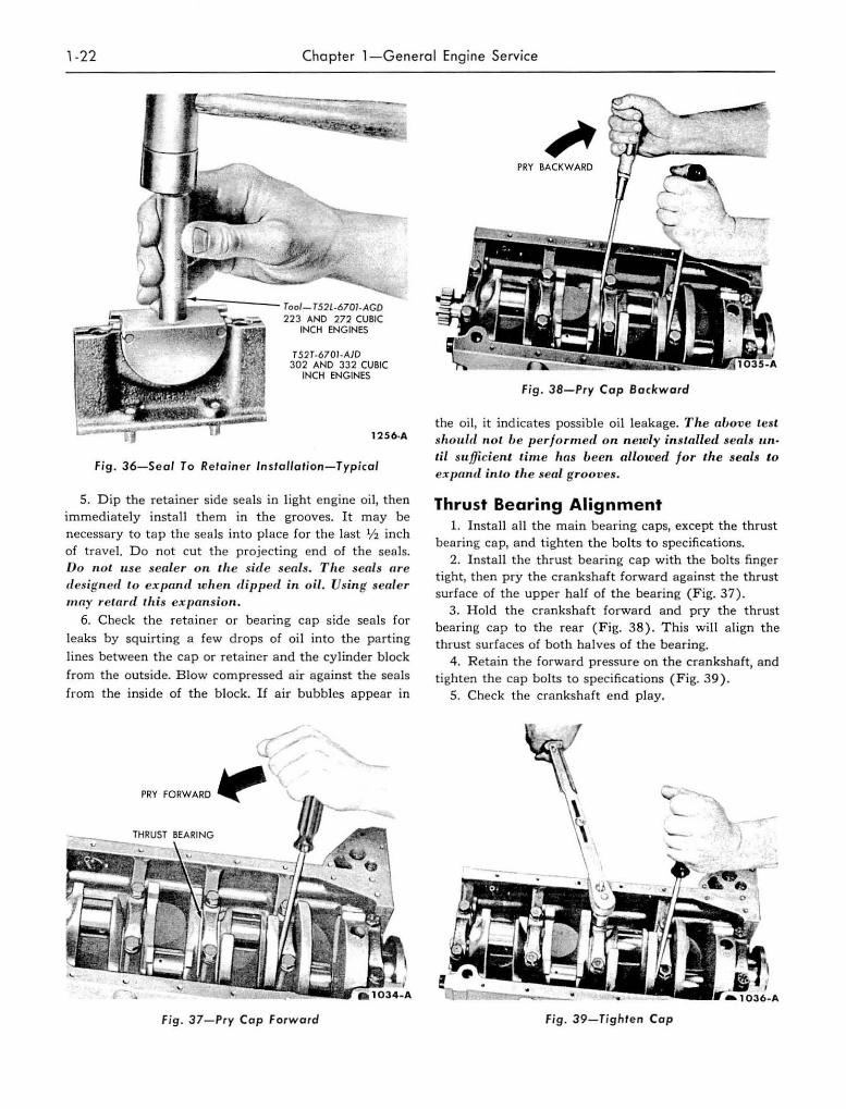
2. I nstall the new seal, firmly packing it, in the cylin
d er block (Fig. 35) . After installation, cut the seals flush
without any frayed edges overlapping, if necessary.
3. Firmly pack the new journal seal in the retainer
or bearing cap (Fig. 36). Afte r insta llation cut the seals
flu sh, if necessary.
4. Coat the rear oi l seal retainer to block mating face
with sealer, install the retainer and tighten the bolts to
23-28 foot-pounds torque.
Tool- T52l.670J.AGD(223 OR 272 CUBIC INCH Tool- T52T·670J-AJD (302 OR 332 CUBIC INCH ENGINE) 1254-A
Fig . 35-Seol To Block Installorion-Typical
1-22 Chapte r l -Gene ra l Eng ine Service
1:;;;:;;;;;---- Too/_ T52L-670l·AGD 223 ANO 272 CUBIC
INCH ENGINES
T52T-670J-AJD 302 AND 332 CUBIC
INCH ENGINES
1256 ·A
Fig. 36-Sea l To Reta in er In stallation-Typical
5. Dip the retainer side seals in light engine oi l, the n immediately install them in the grooves. It may be necessary to tap the seals into place for the last 1/2 inch of travel. Do not cut the projecting end of the seals. Do not use sealer 0 11 the s;fie seals. T he seals are des igned 10 expand when d ip ped ;n o il . Using sealer may retard th is expan sion .
6. Check the retainer or bearing cap side seals for
leaks by squirting a few drops of oil into the parting
lines between the cap or retainer and the cylinder b lock
from the outside. Blow compressed air against the seals
from the inside of the block. If air bubbles appear in
PRY FORWARD JtIJ
c'. Fig . 37-Pry Cap For w ard
PRY BACKWARD
Fig, 38-Pry Cap Backward
the oil, it indicates possible oil leakage. T he above les t should n o t be perfo rmed o n newly imfi.alled seals unI.if su ffi cient time has been allowed f o r the seal j t.o expand into th e seal grooves .
Thrust Bearing Alignment 1. Install a ll the main bearing caps, except the thrust
bearing cap, and tighten the bolts to specifications. 2. I nstall the thrust bearing cap with the bolts finger
tight, then pry the crankshaft forward against the thrust surface of the upper half of the bearing (Fig, 37),
3 . Hold the crankshaft forward and pry the thrust bearing cap to the rear (Fig. 38). T his will align the thrust surfaces of both halves of the bearing.
4. R etain the forward pressure on t he crankshaft, and tighten the cap bolts to specifications (Fig. 39) .
5. Check the crankshaft end play.
Fig. 39-Tighte n Cop
Section 8-Flywhee l 1-23
8. FLYWHEEL
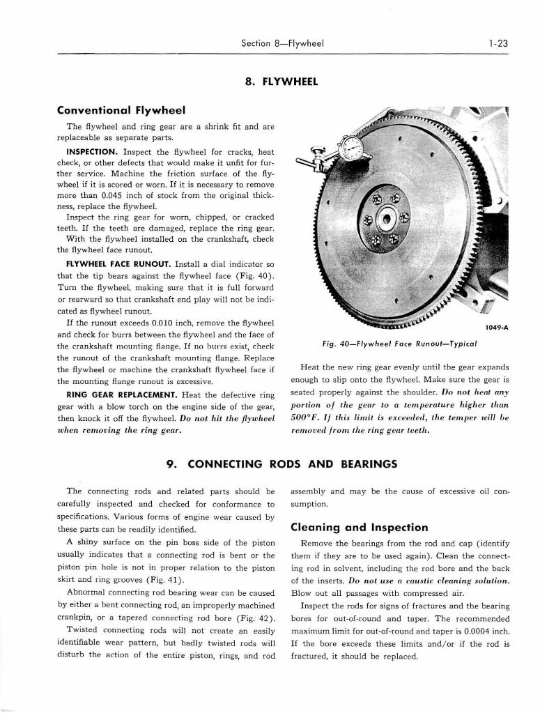
Conventional Flywheel
The flywheel and ring gear are a shrink fit and are replaceable as separate parts.
INSPECTION. I nspect the flywheel for cracks, heat check, or other defects that would make it unfit for further service. M achine the friction surface of the flywheel if it is scored or worn. If it is necessary to remove more than 0.045 inch of stock from the original thickness, replace the flywheel.
Inspect the ring gear for worn, chipped, or cracked teeth. If the teeth are damaged, replace the ring gear.
With the flywheel installed on the crankshaft, check the flywheel fa ce runout.
FLYWHEEL FACE RUN OUT. Install a dial indicator so
that the tip bears against the flywhe el face (Fig. 40 ).
Turn the flywheel, making sure that it is full forward
or rearward so that crankshaft end play will not be indi
cated as flywheel runout.
If the runout exceeds 0.010 inch, remove the flywheel
and check for burrs between the flywheel and the face of
the crankshaft mount in g fl ange. If no burrs exist, check
the runaut of the crankshaft mounting fl a nge. Replace
the flywheel or machine the crankshaft flywheel face if
the mounting flan ge runout is excessive.
RING GEAR REPLACEMENT. H eat the defective ring gear with a b low torch on the engine side of the gear,
then knock it off the flywheel. Do not hit the flywheel
when removing the ring gear.
Fig . 40-Flywh ee l Face Runout-Typico/
Heat the new ring gear evenly until the gear expands
enough to slip onto the fl ywheel. M a ke sure the gear is
seated properly against the shoulder. Do noJ heal (IllY
portioll of the gear to n temperature high er th an
500°F. If this limit is exceeded, th e temper will f, e
removed from Ih e ring gear teeth.
9. CONNECTING RODS AND BEARINGS
The connecting rods and related parts should be
carefully inspected and checked for conformance to
specifications. Various forms of engine wear caused by
these parts can be readily identified.
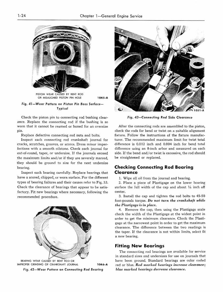
A shiny surface on the pin boss side of the piston
usually indicates that a connecting rod is bent or the
piston pin hole is not in proper relation to the piston
skirt and ring grooves (Fig. 41).
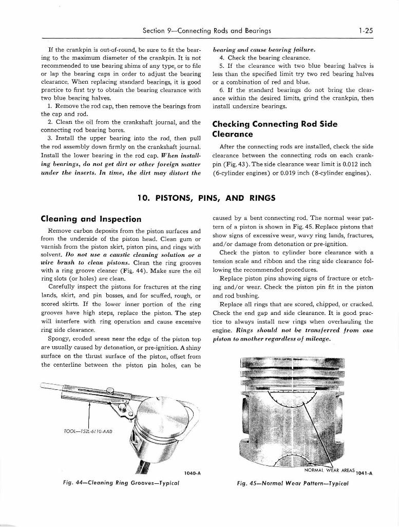
Abnormal connecting rod bearing wea r can be caused
by either a bent connecting rod , an improperly machined
crank pin, or a tapered connecting rod bore (Fig. 42).
Twisted connecting rods will not create an easily
identifiable wear pattern, but badly twisted rods wi ll
disturb the a ction of the entire piston, rings, and rod
assembly and may be the cause of excessive oil con
sumption.
Cleaning and Inspection R emove the bearings from the rod a nd cap (identify
them if they a re to be used again). Clean the connect
ing rod in solvent, including the rod bore and the back
of the inserts. Do not use (l caustic cleaning sulutiun.
Blowout a lJ passages with compressed a ir.
Inspect the rods for signs of fractures and the bearing
bo res for out-of-round a nd taper. The recommended
ma ximum limit for out-of-round and taper is 0.0004 inch.
If the bore exceeds these limi ts and /or if the rod is
fractured, it should be replaced.
1-24 Chapter 1-General Engine Service
OR MISALIGNED PISTON PIN HOLE 104S-A
Fig. 41-Wear Paftern on Piston Pin Boss Surface
Typical
Check the piston pin to connecting rod bushing clearance. Replace the connecting rod if the bushing is so worn that it cannot be reamed or honed for an oversize pin.
Replace defect ive connecting rod nuts and bolts. Inspect each connecting rod crankshaft journal for
cracks, scratches, grooves, or scores. Dress minor imperfections with a smooth oilstone. Check each journal fo r out-oC-round, taper, or undersize. If the journals exceed
the maximum limits and/or if they are severely marred,
they should be ground to size for the next undersize
bearing.
Inspect each bearing carefully. Replace bearings that
have a scored, chipped, or worn surface. For the different
types of bearing failures and their causes refer to Fig. 33.
Check the clearance of bearings that appear to be satis
factory. Fit new bear ings where necessary, following the
recommended procedure.
BEARING WEAR
IMPROPER GRINDING OF CRANKSHAFT JOURNAL 1046-A
Fig . 42-Wear Pattern on Connecting Rod Bearing
fig. 43-Connecting Rod Side Clearance
After the connecting rods are assembled to the piston, check the rods for bend or twist on a suitable a lignment fixture. Follow the instruct ions of the fixture manufacturer. The recommended maximum limit for twist total difference is 0.012 inch and 0.004 inch for bend total difference using an 8-inch arbor and measured on each side. If the bend and/or twist is excessive, t he rod should be straightened or replaced..
Checking Connecting Rod Bearing Clearance
1. Wipe all oil from the journal and bearing. 2. P lace a piece of Plastigage on t he lower bearing
surface the full width of the cap and about 1/ 4 inch off center.
3. Install the cap and tighten the rod bolts to 45-50 foot-pounds torque. Do not turn the crankshaft l()/tiie the Plasligage is in place.
4. Remove the cap, then using the Plastigage scale check the width of the Plastigage at the widest point in order to get the minimum clearance. Check the Plastigage at the narrowest point in order to get the maximum clearance. The difference between the two readings is the taper. If t he clearance is not within limits, select fit a new bearing.
Fitting New Bearings The connecting rod bearings are available for service
in standard sizes and undersizes for use on journals that have been ground. Standard bearings are color coded red or b lue. R ed marked bearings increase clearance; blue marked bearings dec reuse clearance.
Section 9-Connecling Rods and Bearings 1-25
If the crankpin is out-DC-round, be sure to fit the bear
ing to the maximum diameter of the crankpin. It is not recommended to use bearing shims of any type, or to file or lap the bearing caps in order to adjust the bearing clearance. When replacing standard bearings, it is good practice to first try to obtain the bearing clearance with two blue bearing halves.
1. Remove the rod cap, then remove the bearings from the cap and rod.
2. Clean the oil from the crankshaft journal, and the connecting rod bearing bores.
3. Install the upper bearing into the rod, then pull
the rod assembly down firmly on the crankshaft journal.
Install the lower bearing in the rod cap. When installing bearings, do not get dirt or other foreign matter under t.he inserts. In lime, th e dirt. may distort the
I)earing and cause bearing fa ilure. 4. Check the bearing clearance. 5. If the clearance with two blue bearing halves is
Jess than the specified limit try two red bearing halves or a combination of red and blue.
6. If the standard bearings do not bring the clearance within the desired limits, grind the crankpin, then install undersize bearings.
Checking Connecting Rod Side Clearance
After the connecting rods are installed, check the side
clearance between the connecting rods on each crank
pin (Fig.43). The side clearance wear limit is 0.012 inch
(6-cylinder engines) or 0.019 inch (8-cylinder engines).
10. PISTONS, PINS, AND RINGS
Cleaning and Inspection Remove carbon deposits from the piston surfaces and
from the underside of the piston head. Clean gum or varnish from the piston skirt, piston pins, and rings with solvent. Do n ot. use a caustic cleaning solution or a wire brush La clean pistons. Clean the ring grooves with a ring groove cleaner (Fig,. 44). Make sure the oil ring slots (or holes) are clean.
Carefully inspect the pistons for fractures at the ring
lands, skirt, and pin bosses, and for scuffed, rough, or
scored skirts. If the lower inner portion of the ring
grooves have high steps, replace the piston. The step
will interfere with ring operation and cause excessive ring side clearance.
Spongy, eroded areas near the edge of the piston top
are usually caused by detonation, or pre-ignition. A shiny
surface on the thrust surface of the piston, offset from
the centerline between the p iston pin holes, can be
Fig. 44-C/ean in g Ring Grooves-T ypica l
caused by a bent connecting rod. The normal wear pat
tern of a piston is shown in Fig. 45. Replace pistons that
show signs of excessive wear, wavy ring lands, fractures,
and / or damage from detonation or pre-ignition.
Check the piston to cylinder bore clearance with a tension scale and ribbon and the ring side clearance fol
lowing the recommended procedures.
Replace piston pins showing signs of fracture or etch
ing and / or wear. Check the piston pin fit in the piston
and rod bushing.
Replace all rings that are scored, chipped, or cracked.
Check the end gap and side clearance. It is good prac
tice to always install new rings when overhauling the
engine. Rings should not be transferred fro m one
piston to n1wlher regardless of m ileage.
AREAS 104 l-A
Fi g. 45-Normal Wear Patfern-T ypical
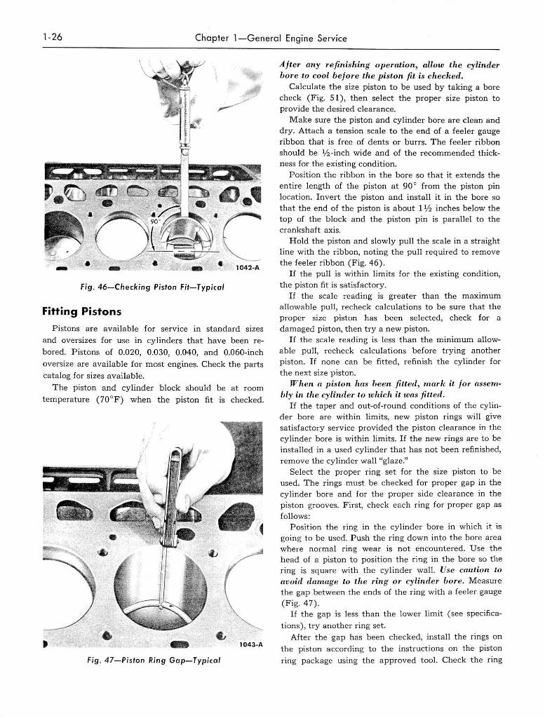
1-26 Chapter 1-General Engine Service
Fig. 46-Checking Piston Fit-Typical
Fitting Pistons
Pistons are available for service in standard sizes
and oversizes for use in cylinders that have been re
bored. Pistons of 0.020, 0.030, 0.040, and 0.060-inch oversize are available for most engines. Check the parts
catalog for sizes available.
The piston and cylinder block should be at room
temperature (70°F) when the piston fit is checked.
-Fig. 47-pjston Ring Gap-Typical
After any refinishing operation, allow the cylinder bore Lo cool before the piston fit is checked.
Calculate the size piston to be used by taking a bore check (Fig. 51), then select the proper size piston to provide the desired clearance.
Make sure the piston and cylinder bore are clean and dry, Attach a tension scale to the end of a feeler gauge ribbon that is free of dents or burrs. The feeler ribbon should be 1/2-inch wide and of the recommended thickness for the existing condition.
Position the ribbon in the bore so that it extends the entire length of the piston at 90 0 from the piston pin location. Invert the piston and install it in the bore so that the end of the piston is about 1 % inches below the top of the block and the piston pin is parallel to the crankshaft axis.
Hold the piston and slowly pull the scale in a straight line with the ribbon, noting the pull required to remove the feeler ribbon (Fig. 46).
If the pull is within limits for the existing condition, the piston fit is satisfactory.
If the scale reading is greater than the maximum allowable pull, recheck calculations to be sure that the proper size piston has been selected, check for a damaged piston, then try a new piston.
If the scale reading is less than the minimum allowable pull, recheck calculations before trying another piston. If none can be fitted, refinish the cylinder for the next size piston.
When a piston has heen jilleri, mark i/. for assembly in the cylinder to which it was filled.
If the taper and out-of-round conditions of the cylinder bore are within limits, new piston rings will give satisfactory service provided the piston clearance in the cylinder bore is within limits. If the new rings are to be installed in a used cylinder that has not been refinished, remove the cylinder wall "glaze."
Select the proper ring set for the size piston to be used. The rings must be checked for proper gap in the cylinder bore and for the proper side clearance in the piston grooves. First, check each ring for proper gap as follows:
Position the ring in the cylinder bore in which it is going to be used. Push the ring down into the bore area where normal ring wear is not encountered. Use the head of a piston to position the ring in the bore so the ring is square with the cy linder wall. Use caution to avoid damage to the ring or cylinder bore. M easure the gap between the ends of the ring with a feeler gauge (Fig. 47).
If the gap is less than the lower limit (see specifica
tions), try another ring set. After the gap has been checked, install the rings on
the piston according to the instructions on the piston ring package using the approved tool. Check the ring