Embed Size (px)
Citation preview
Copyright © 2010, Forel Publishing Company, LLC, Woodbridge, Virginia
All Rights Reserved. No part of this book may be used or reproduced in any manner whatsoever without written permission of Forel Publishing Company, LLC. For information write to Forel
Publishing Company, LLC, 3999 Peregrine Ridge Ct., Woodbridge, VA 22192
1959 Ford Car Shop Manual EAN: 978-1-60371-053-4
ISBN: 1-60371-053-1
Forel Publishing Company, LLC 3999 Peregrine Ridge Ct. Woodbridge, VA 22192
Email address: [email protected] Website: http://www.ForelPublishing.com
This publication contains material that is reproduced and distributed under a license from Ford Motor Company. No further reproduction or distribution of the Ford Motor Company material is
allowed without the express written permission of Ford Motor Company.
NNoottee ffrroomm tthhee EEddiittoorr This product was created from the original Ford Motor Company’s publication. Every effort has been made to use the original scanned images, however, due to the condition of the material; some pages have been modified to remove imperfections.
Disclaimer
Although every effort was made to ensure the accuracy of this book, no representations or warranties of any kind are made concerning the accuracy, completeness or suitability of the information, either expressed or implied. As a result, the information contained within this book should be used as general information only. The author and Forel Publishing Company, LLC shall have neither liability nor responsibility to any person or entity with respect to any loss or damage caused, or alleged to be caused, directly or indirectly by the information contained in this book. Further, the publisher and author are not engaged in rendering legal or other professional services. If legal, mechanical, electrical, or other expert assistance is required, the services of a competent professional should be sought.
FOREWORD
This manual provides information for the proper servicing of 1959
Ford Cars, Station Wagons, Courier, and Ranchero. The
descriptions and specifications contained in this manual were
in effect at the time the manual was approved for printing.
The Ford Division of Ford Motor Company reserves the right
to discontinue models at any time, or change specifications
or design, without notice and without incurring obligation.
SERVICE DEPARTMENTF O R D D I V I S I O NFORD MOTOR COMPANY
I1 9 5 9 FORD CAR SHOP MANUAL
iGROUP I
ENGINES ANDEXHAUST SYSTEMS
PAGE
P A R T 1 - 1 GENERAL ENGINE SERVICE 1-2
P A R T 1 - 2 MILEAGE MAKER SIX 1-25
P A R T 1 - 3 THUNDERBIRD 292 V-8 1-45
P A R T 1 - 4 THUNDERBIRD 332 AND 352 SPECIAL V-8, AND352 POLICE SPECIAL V-8 1-68
P A R T 1 - 5 EXHAUST SYSTEMS 1-93
P A R T 1 - 6 SPECIFICATIONS 1-98
1-2
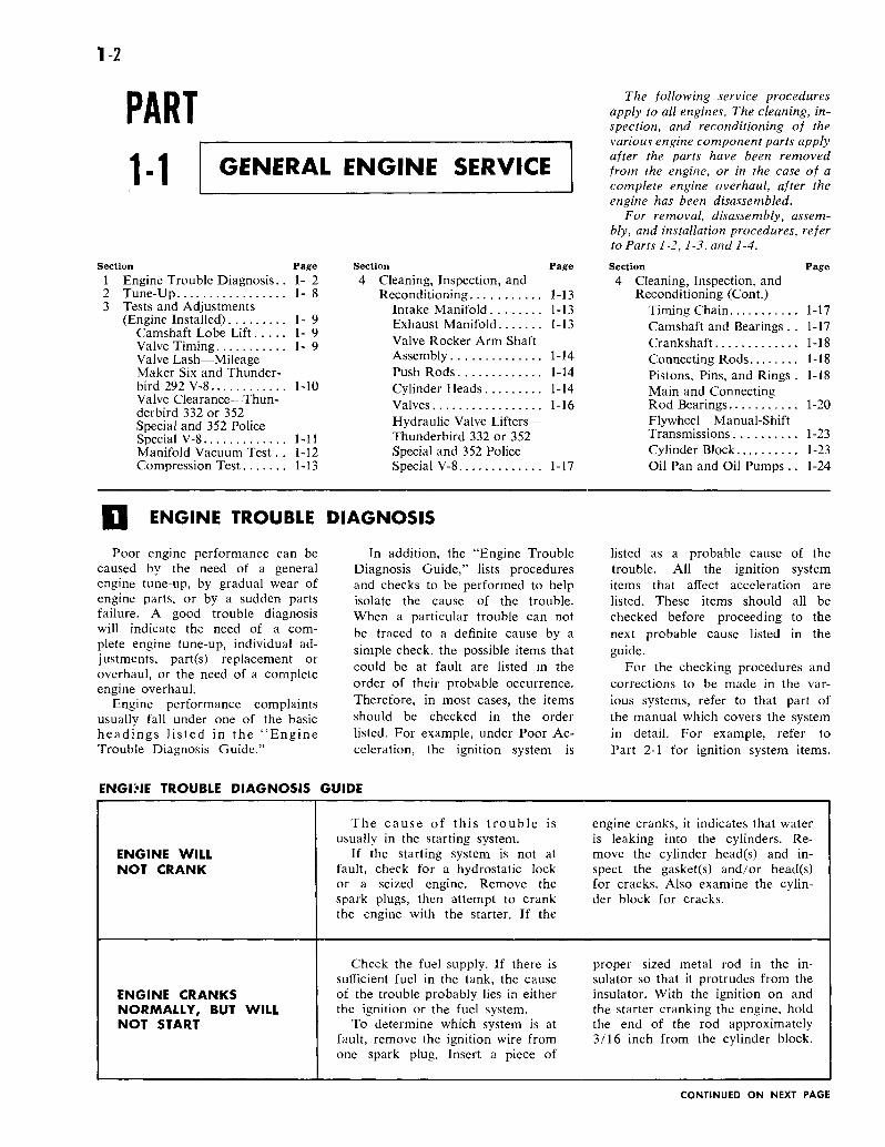
PART1-1 GENERAL ENGINE SERVICE
Section Page1 Engine Trouble Diagnosis.. 1-22 Tune-Up 1- 83 Tests and Adjustments
(Engine Installed) 1-9Camshaft Lobe Lift 1-9Valve Timing 1-9Valve Lash—MileageMaker Six and Thunder-bird 292 V-8 1-10Valve Clearance—Thun-derbird 332 or 352Special and 352 PoliceSpecial V-8 1-11Manifold Vacuum Test. . 1-12Compression Test 1-13
Section Page4 Cleaning, Inspection, and
Reconditioning 1-13Intake Manifold 1-13Exhaust Manifold 1-13Valve Rocker Arm ShaftAssembly 1-14Push Rods 1-14Cylinder Heads 1-14Valves 1-16Hydraulic Valve Lifters—Thunderbird 332 or 352Special and 352 PoliceSpecial V-8 1-17
The following service proceduresapply to all engines. The cleaning, in-spection, and reconditioning of thevarious engine component parts applyafter the parts have been removedfrom the engine, or in the case of acomplete engine overhaul, after theengine has been disassembled.
For removal, disassembly, assem-bly, and installation procedures, referto Parts 1-2, 1-3, and 1-4.
Section Page4 Cleaning, Inspection, and
Reconditioning (Cont.)Timing Chain 1-17Camshaft and Bearings . . 1-17Crankshaft 1-18Connecting Rods 1-18Pistons, Pins, and Rings . 1-18Main and ConnectingRod Bearings 1-20Flywheel—Manual-ShiftTransmissions 1-23Cylinder Block 1-23Oil Pan and Oil Pumps .. 1-24
ENGINE TROUBLE DIAGNOSIS
Poor engine performance can becaused by the need of a generalengine tune-up, by gradual wear ofengine parts, or by a sudden partsfailure. A good trouble diagnosiswill indicate the need of a com-plete engine tune-up, individual ad-justments, part(s) replacement oroverhaul, or the need of a completeengine overhaul.
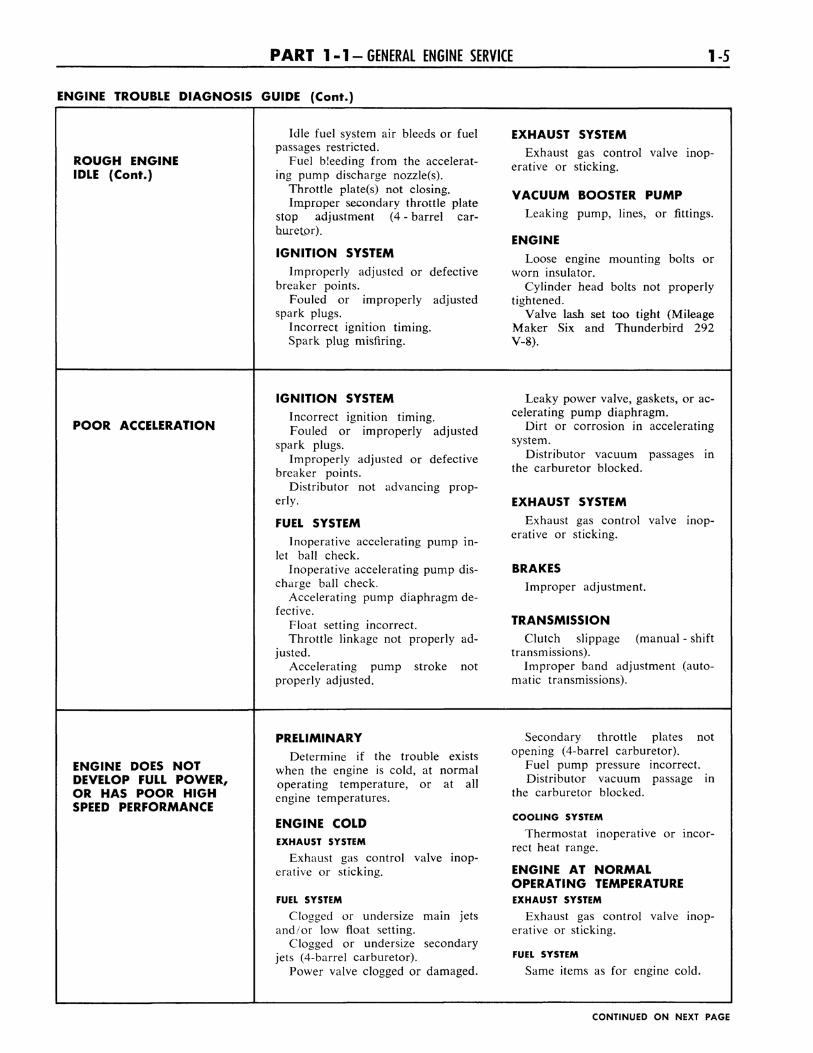
Engine performance complaintsusually fall under one of the basicheadings listed in the "EngineTrouble Diagnosis Guide."
In addition, the "Engine TroubleDiagnosis Guide," lists proceduresand checks to be performed to helpisolate the cause of the trouble.When a particular trouble can notbe traced to a definite cause by asimple check, the possible items thatcould be at fault are listed in theorder of their probable occurrence.Therefore, in most cases, the itemsshould be checked in the orderlisted. For example, under Poor Ac-celeration, the ignition system is
listed as a probable cause of thetrouble. All the ignition systemitems that affect acceleration arelisted. These items should all bechecked before proceeding to thenext probable cause listed in theguide.
For the checking procedures andcorrections to be made in the var-ious systems, refer to that part ofthe manual which covers the systemin detail. For example, refer toPart 2-1 for ignition system items.
ENGINE TROUBLE DIAGNOSIS GUIDE
ENGINE WILLNOT CRANK
ENGINE CRANKSNORMALLY, BUT WILLNOT START
The cause of this trouble is engine cranks, it indicates that waterusually in the starting system. is leaking into the cylinders. Re-
If the starting system is not at move the cylinder head(s) and in-fault, check for a hydrostatic lock spect the gasket(s) and/or head(s)or a seized engine. Remove the for cracks. Also examine the cylin-spark plugs, then attempt to crank der block for cracks,the engine with the starter. If the
Check the fuel supply. If there is proper sized metal rod in the in-sufficient fuel in the tank, the cause sulator so that it protrudes from theof the trouble probably lies in either insulator. With the ignition on andthe ignition or the fuel system. the starter cranking the engine, hold
To determine which system is at the end of the rod approximatelyfault, remove the ignition wire from 3/16 inch from the cylinder block,one spark plug. Insert a piece of
CONTINUED ON NEXT PAGE
P A R T 1 -1 -GENERAL ENGINE SERVICE 13
ENGINE TROUBLE DIAGNOSIS GUIDE (Continued)
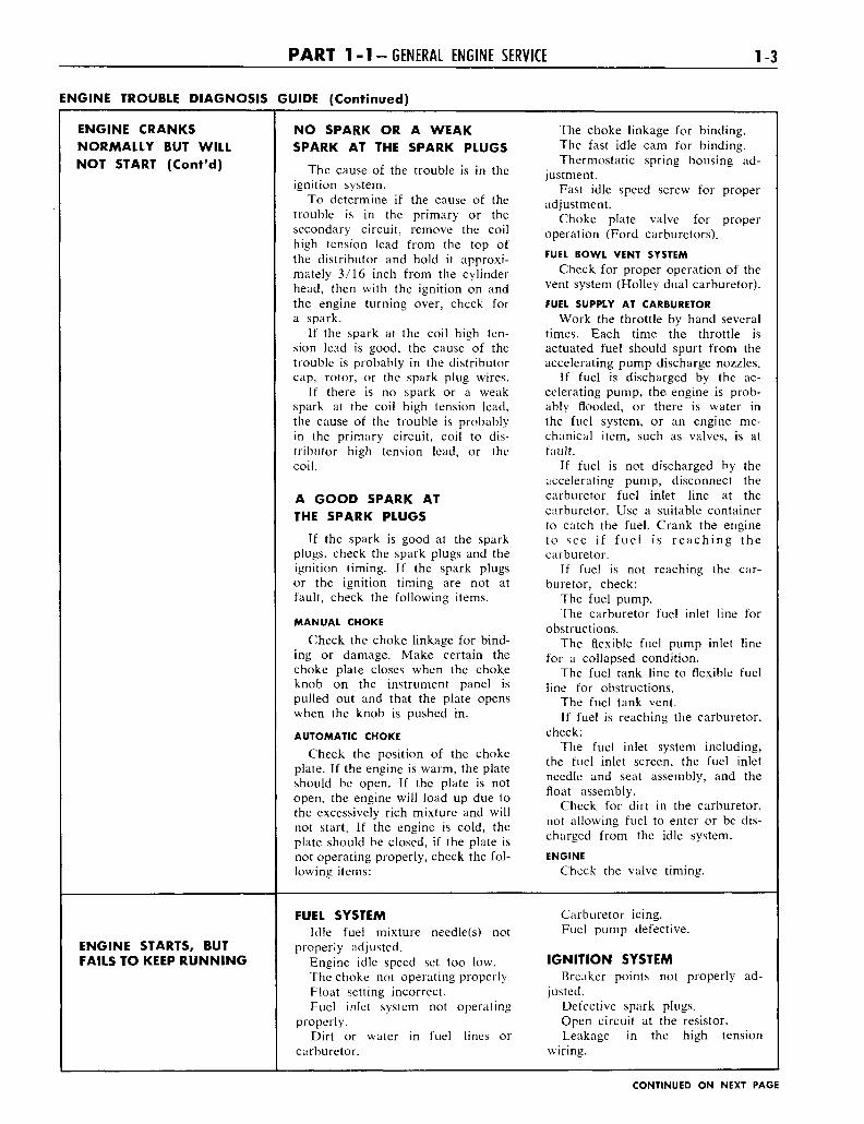
ENGINE CRANKSNORMALLY BUT WILLNOT START (Cont'd)
NO SPARK OR A WEAKSPARK AT THE SPARK PLUGS
The cause of the trouble is in theignition system.
To determine if the cause of thetrouble is in the primary or thesecondary circuit, remove the coilhigh tension lead from the top ofthe distributor and hold it approxi-mately 3/16 inch from the cylinderhead, then with the ignition on andthe engine turning over, check fora spark.
If the spark at the coil high ten-sion lead is good, the cause of thetrouble is probably in the distributorcap, rotor, or the spark plug wires.
If there is no spark or a weakspark at the coil high tension lead,the cause of the trouble is probablyin the primary circuit, coil to dis-tributor high tension lead, or thecoil.
A GOOD SPARK ATTHE SPARK PLUGS
If the spark is good at the sparkplugs, check the spark plugs and theignition timing. If the spark plugsor the ignition timing are not atfault, check the following items.
MANUAL CHOKE
Check the choke linkage for bind-ing or damage. Make certain thechoke plate closes when the chokeknob on the instrument panel ispulled out and that the plate openswhen the knob is pushed in.
AUTOMATIC CHOKE
Check the position of the chokeplate. If the engine is warm, the plateshould be open. If the plate is notopen, the engine will load up due tothe excessively rich mixture and willnot start. If the engine is cold, theplate should be closed, if the plate isnot operating properly, check the fol-lowing items:
The choke linkage for binding.The fast idle cam for binding.Thermostatic spring housing ad-
justment.Fast idle speed screw for proper
adjustment.Choke plate valve for proper
operation (Ford carburetors).FUEL BOWL VENT SYSTEM
Check for proper operation of thevent system (Holley dual carburetor).FUEL SUPPLY AT CARBURETOR
Work the throttle by hand severaltimes. Each time the throttle isactuated fuel should spurt from theaccelerating pump discharge nozzles.
If fuel is discharged by the ac-celerating pump, the engine is prob-ably flooded, or there is water inthe fuel system, or an engine me-chanical item, such as valves, is atfault.
If fuel is not discharged by theaccelerating pump, disconnect thecarburetor fuel inlet line at thecarburetor. Use a suitable containerto catch the fuel. Crank the engineto see if fuel is reaching thecarburetor.
If fuel is not reaching the car-buretor, check:
The fuel pump.The carburetor fuel inlet line for
obstructions.The flexible fuel pump inlet line
for a collapsed condition.The fuel tank line to flexible fuel
line for obstructions.The fuel tank vent.If fuel is reaching the carburetor,
check:The fuel inlet system including,
the fuel inlet screen, the fuel inletneedle and seat assembly, and thefloat assembly.
Check for dirt in the carburetor,not allowing fuel to enter or be dis-charged from the idle system.
ENGINE
Check the valve timing.
ENGINE STARTS, BUTFAILS TO KEEP RUNNING
FUEL SYSTEMIdle fuel mixture needle(s) not
properly adjusted.Engine idle speed set too low.The choke not operating properly.Float setting incorrect.Fuel inlet system not operating
properly.Dirt or water in fuel lines or
carburetor.
Carburetor icing.Fuel pump defective.
IGNITION SYSTEMBreaker points not properly ad-
justed.Defective spark plugs.Open circuit at the resistor.Leakage in the high tension
wiring.
CONTINUED ON NEXT PAGE
1-4 G R O U P 1-ENGINES AND EXHAUST SYSTEMS
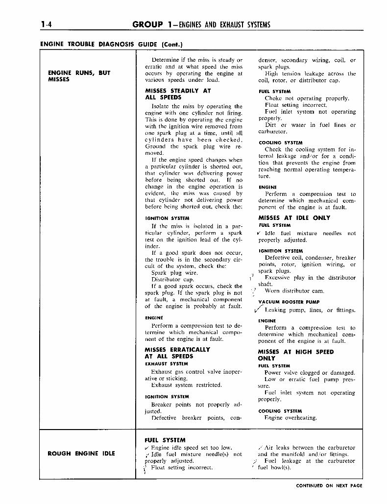
ENGINE TROUBLE DIAGNOSIS
ENGINE RUNS, BUTMISSES
ROUGH ENGINE IDLE
GUIDE (Cont.)
Determine if the miss is steady orerratic and at what speed the missoccurs by operating the engine atvarious speeds under load.
MISSES STEADILY ATALL SPEEDS
Isolate the miss by operating theengine with one cylinder not firing.This is done by operating the enginewith the ignition wire removed fromone spark plug at a time, until allcylinders have been checked.Ground the spark plug wire re-moved.
If the engine speed changes whena particular cylinder is shorted out,that cylinder was delivering powerbefore being shorted out. If nochange in the engine operation isevident, the miss was caused bythat cylinder not delivering powerbefore being shorted out, check the:
IGNITION SYSTEM
If the miss is isolated in a par-ticular cylinder, perform a sparktest on the ignition lead of the cyl-inder.
If a good spark does not occur,the trouble is in the secondary cir-cuit of the system, check the:
Spark plug wire.Distributor cap.If a good spark occurs, check the
spark plug. If the spark plug is notat fault, a mechanical componentof the engine is probably at fault.
ENGINE
Perform a compression test to de-termine which mechanical compo-nent of the engine is at fault.
MISSES ERRATICALLYAT ALL SPEEDSEXHAUST SYSTEM
Exhaust gas control valve inoper-ative or sticking.
Exhaust system restricted.
IGNITION SYSTEM
Breaker points not properly ad-justed.
Defective breaker points, con-
FUEL SYSTEMv Engine idle speed set too low./ Id le fuel mixture needle(s) notproperly adjusted.f Float setting incorrect.<
denser, secondary wiring, coil, orspark plugs.
High tension leakage across thecoil, rotor, or distributor cap.
FUEL SYSTEM
Choke not operating properly.Float setting incorrect.Fuel inlet system not operating
properly.Dirt or water in fuel lines or
carburetor.
COOLING SYSTEM
Check the cooling system for in-ternal leakage and/or for a condi-tion that prevents the engine fromreaching normal operating tempera-ture.
ENGINE
Perform a compression test todetermine which mechanical com-ponent of the engine is at fault.
MISSES AT IDLE ONLYFUEL SYSTEM
v Idle fuel mixture needles notproperly adjusted.
IGNITION SYSTEM
Defective coil, condenser, breakerpoints, rotor, ignition wiring, orspark plugs.
•? Excessive play in the distributor'" shaft.\? Worn distributor cam.
VACUUM BOOSTER PUMP
i/ Leaking pump, lines, or fittings.
ENGINE
Perform a compression test todetermine which mechanical com-ponent of the engine is at fault.
MISSES AT HIGH SPEEDONLYFUEL SYSTEM
Power valve clogged or damaged.Low or erratic fuel pump pres-
sure.Fuel inlet system not operating
properly.
COOLING SYSTEM
Engine overheating.
/ Air leaks between the carburetorand the manifold and/or fittings.
;/ Fuel leakage at the carburetor' fuel bowl(s).
CONTINUED ON NEXT PAGE
1-6 G R O U P 1-ENGINES AND EXHAUST SYSTEMS
ENGINE TROUBLE DIAGNOSIS
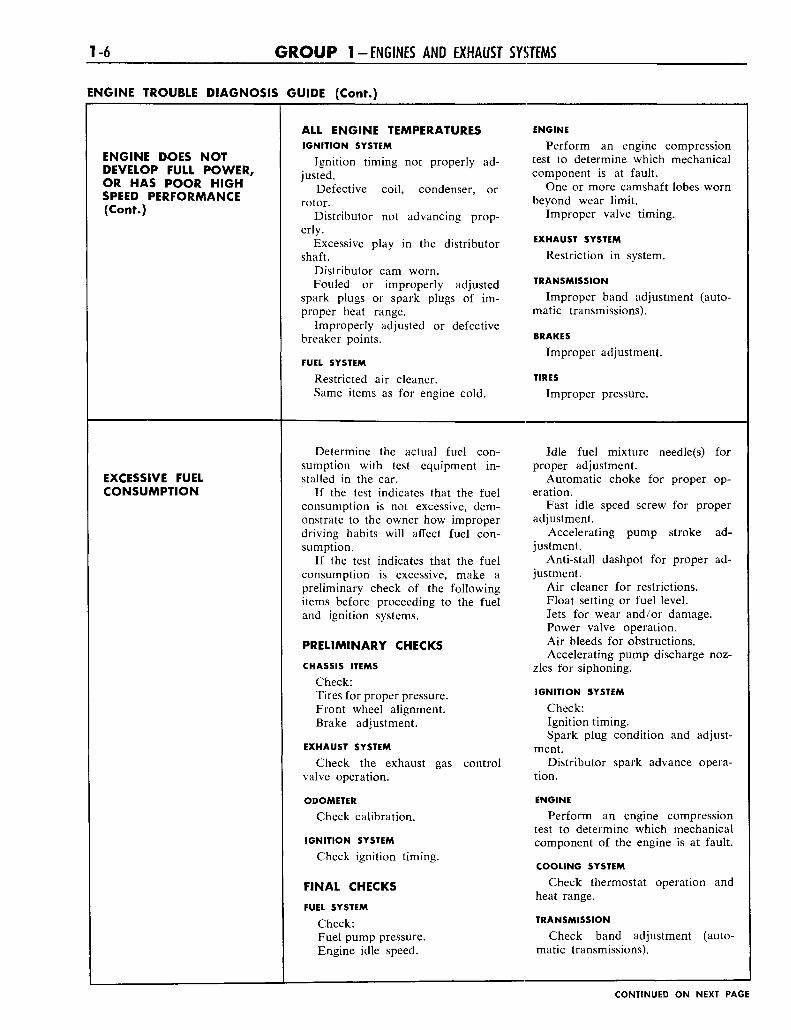
ENGINE DOES NOTDEVELOP FULL POWER,OR HAS POOR HIGHSPEED PERFORMANCE(Cont.)
EXCESSIVE FUELCONSUMPTION
GUIDE (Cont.)
ALL ENGINE TEMPERATURESIGNITION SYSTEM
Ignition timing not properly ad-justed.
Defective coil, condenser, orrotor.
Distributor not advancing prop-
erly.Excessive play in the distributor
shaft.Distributor cam worn.Fouled or improperly adjusted
spark plugs or spark plugs of im-proper heat range.
Improperly adjusted or defectivebreaker points.
FUEL SYSTEM
Restricted air cleaner.Same items as for engine cold.
Determine the actual fuel con-sumption with test equipment in-stalled in the car.
If the test indicates that the fuelconsumption is not excessive, dem-onstrate to the owner how improperdriving habits will affect fuel con-sumption.
If the test indicates that the fuelconsumption is excessive, make apreliminary check of the followingitems before proceeding to the fueland ignition systems.
PRELIMINARY CHECKS
CHASSIS ITEMS
Check:Tires for proper pressure.Front wheel alignment.Brake adjustment.
EXHAUST SYSTEM
Check the exhaust gas controlvalve operation.
ODOMETER
Check calibration.
IGNITION SYSTEM
Check ignition timing.
FINAL CHECKS
FUEL SYSTEM
Check:Fuel pump pressure.Engine idle speed.
ENGINE
Perform an engine compressiontest to determine which mechanicalcomponent is at fault.
One or more camshaft lobes wornbeyond wear limit.
Improper valve timing.
EXHAUST SYSTEM
Restriction in system.
TRANSMISSION
Improper band adjustment (auto-matic transmissions).
BRAKES
Improper adjustment.
TIRES
Improper pressure.
Idle fuel mixture needle(s) forproper adjustment.
Automatic choke for proper op-eration.
Fast idle speed screw for properadjustment.
Accelerating pump stroke ad-justment.
Anti-stall dashpot for proper ad-justment.
Air cleaner for restrictions.Float setting or fuel level.Jets for wear and/or damage.Power valve operation.Air bleeds for obstructions.Accelerating pump discharge noz-
zles for siphoning.
IGNITION SYSTEM
Check:Ignition timing.Spark plug condition and adjust-
ment.Distributor spark advance opera-
tion.
ENGINE
Perform an engine compressiontest to determine which mechanicalcomponent of the engine is at fault.
COOLING SYSTEM
Check thermostat operation andheat range.
TRANSMISSION
Check band adjustment (auto-matic transmissions).
CONTINUED ON NEXT PAGE
P A R T 1 -1 -GENERAL ENGINE SERVICE 1-7
ENGINE TROUBLE DIAGNOSIS GUIDE (Cont.)
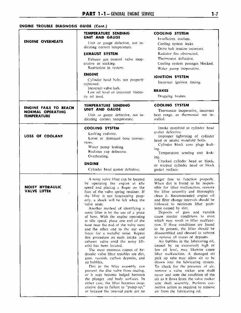
ENGINE OVERHEATS
ENGINE FAILS TO REACHNORMAL OPERATINGTEMPERATURE
LOSS OF COOLANT
NOISY HYDRAULICVALVE LIFTER
TEMPERATURE SENDING COOLING SYSTEMUNIT AND GAUGE Insufficient coolant.
Unit or gauge defective, not in- Cooling system leaks,dicating correct temperature. D r j v e b d t t e n s i o n i n c o r r e c t
EXHAUST SYSTEM Radiator fins obstructed.Exhaust gas control valve inop- Thermostat defective,
erative or sticking. Cooling system passages blocked.Restriction in system. Water pump inoperative.
E N G I N E IGNITION SYSTEMCylinder head bolts not properly . . . . .
tightened. Incorrect ignition timing.
Incorrect valve lash. BRAKESLow oil level or incorrect viscos- BRAKES
ity oil used. Dragging brakes.
TEMPERATURE SENDING COOLING SYSTEMUNIT AND GAUGE Thermostat inoperative, incorrect
Unit or gauge defective, not in- heat range, or thermostat not in-dicating correct temperature. stalled.
COOLING SYSTEM Intake manifold to cylinder headLeaking radiator. § a s k e t defective.
. , Improper tightening of cylinderLoose or damaged hose connec- , , . . . .; . , , ,;
. 5 head or intake manifold bolts., , . Cylinder block core plugs leak-
Water pump leaking. •Radiator cap defective. Temperature sending unit leak-Overheating. j n g i
Cracked cylinder head or block,ENGINE o r w a r p e ( j cylinder head or block
Cylinder head gasket defective. gasket surface.
A noisy valve lifter can be located longer free to function properly,by operating the engine at idle When dirt is found to be respon-speed and placing a finger on the sible for lifter malfunction, removeface of the valve spring retainer. If the lifter assembly and thoroughlythe lifter is not functioning prop- clean it. Recommended engine oilerly, a shock will be felt when the and filter change intervals should bevalve seats. followed to minimize lifter prob-
Another method of identifying a lems caused by dirt,noisy lifter is by the use of a piece Deposits of gum and varnishof hose. With the engine operating cause similar conditions to existat idle speed, place one end of the which may result in lifter malfunc-hose near the end of the valve stem tion. If these conditions are foundand the other end to the ear and to be present, the lifter should belisten for a metallic noise. Repeat disassembled and cleaned in solventthis procedure on each intake and to remove all traces of deposits,exhaust valve until the noisy lift- Air bubbles in the lubricating oil,er(s) has been located. caused by an excessively high or
The most common causes of hy- low oil level, may likewise causedraulic valve lifter troubles are dirt, lifter malfunction. A damaged oilgum, varnish, carbon deposits, and pick up tube may allow air to beair bubbles. drawn into the lubricating system.
Dirt in the lifter assembly can To check for the presence of air,prevent the disc valve from seating, remove a valve rocker arm shaftor it may become lodged between cover and note the condition of thethe plunger and body surfaces. In oil as it flows from the valve rockereither case, the lifter becomes inop- arm shaft assembly. Perform cor-erative due to failure to "pump-up," rective action as required to removeor because the internal parts are no air from the lubricating oil.
1-8 G R O U P 1-ENGINES AND EXHAUST SYSTEMS
TUNE-UP
A tune-up is a systematic pro-cedure for testing various enginecomponents, and, if necessary,bringing them within recommendedspecifications to restore engine ef-ficiency and performance.
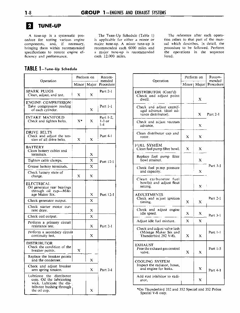
The Tune-Up Schedule (Table 1)is applicable for either a minor ormajor tune-up. A minor tune-up isrecommended each 6000 miles anda major tune-up is recommendedeach 12,000 miles.
The reference after each opera-tion refers to that part of the man-ual which describes, in detail, theprocedure to be followed. Performthe operations in the sequencelisted.
TABLE 1-Tune-Up Schedule
Operation
SPARK PLUGSClean, adjust, and test.
ENGINE COMPRESSIONTake compression reading
of each cylinder.
INTAKE MANIFOLDCheck and tighten bolts.
DRIVE BELTSCheck and adjust the ten-
sion of all drive belts.
BATTERYClean battery cables and
terminals.
Tighten cable clamps.
Grease battery terminals.
Check battery state ofcharge.
ELECTRICALOil generator rear bearings
through oil cup—Mile-age Maker Six.
Check generator output.
Check starter motor cur-rent draw.
Check coil output.
Perform a primary circuitresistance test.
Perform a secondary circuitcontinuity test.
DISTRIBUTORCheck the condition of the
breaker points.
Replace the breaker pointsand the condenser.
Check and adjust breakerarm spring tension.
Lubricate the distributorcam. Oil the lubricatingwick. Lubricate the dis-tributor bushing throughthe oil cup.
Perform on
Minor
X
X*
X
X
t
X
Major
X
X
X
X
X
X
X
X
X
X
X
X
X
X
X
X
X
Recom-mended
Procedure
Part 2-1
Part 1-1
Part 1-2,1-3 or1-4
Part 4-1
Part 12-1
Part 12-1
Part 2-1
Part 2-1
Operation
DISTRIBUTOR (Cont'd)Check and adjust point
dwell.
Check and adjust centrif-ugal advance, (dual ad-vance distributor).
Check and adjust vacuumadvance.
Clean distributor cap androtor.
FUEL SYSTEMClean fuel pump filter bowl.
Replace fuel pump filterbowl strainer.
Check fuel pump pressureand capacity.
Clean carburetor fuelbowl(s) and adjust floatsetting.
ADJUSTMENTSCheck and adjust ignition
timing.
Check and adjust engineidle speed.
Adjust idle fuel mixture.
Check and adjust valve lash(Mileage Maker Six andThunderbird. 292 V-8).
EXHAUSTFree the exhaust gas control
valve.
COOLING SYSTEMInspect the radiator, hoses,
and engine for leaks.
Add rust inhibitor to radi-ator.
Perform on
Minor
X
X
X
X
X
X
X
Major
X
X
X
X
X
X
X
X
X
X
X
X
X
X
X
Recom-mended
Procedure
Part 2-1
Part 3-1
Part 2-1
Part 3-1
Part 1-1
Part 1-5
Part 4-1
•On Thunderbird 332 and 352 Special and 352 PoliceSpecial V-8 only.
P A R T 1 - 1 - GENERAL ENGINE SERVICE 1-9
TESTS AND ADJUSTMENTS (ENGINE INSTALLED)
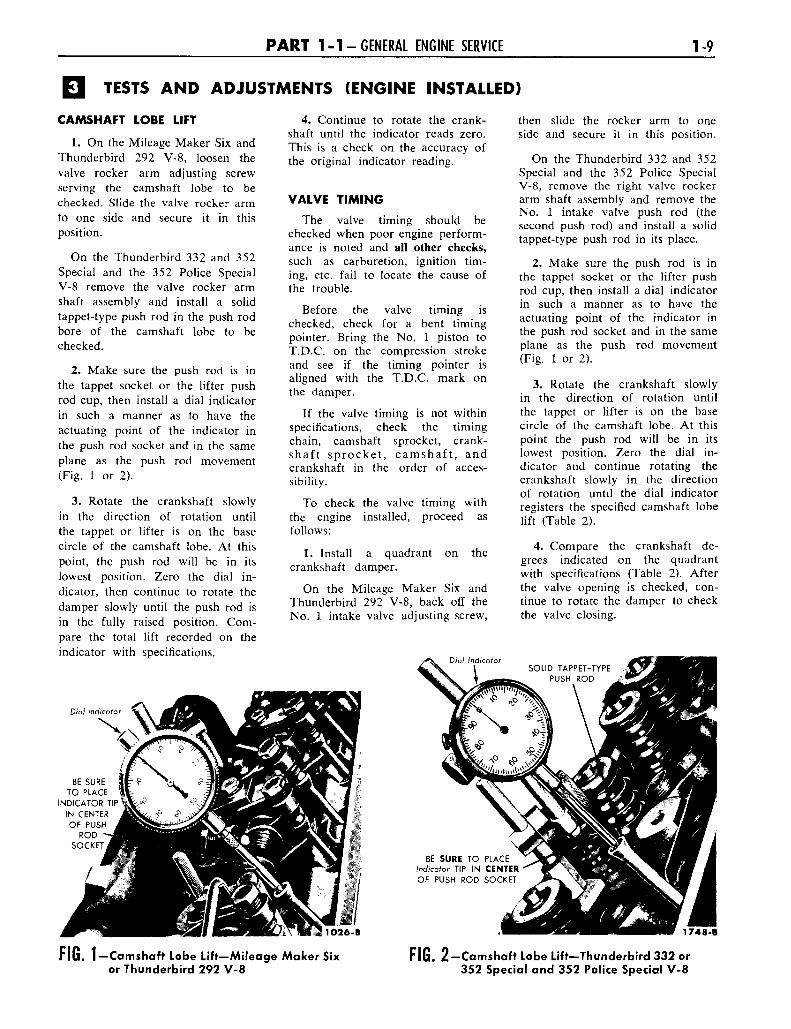
CAMSHAFT LOBE LIFT
1. On the Mileage Maker Six andThunderbird 292 V-8, loosen thevalve rocker arm adjusting screwserving the camshaft lobe to bechecked. Slide the valve rocker armto one side and secure it in thisposition.
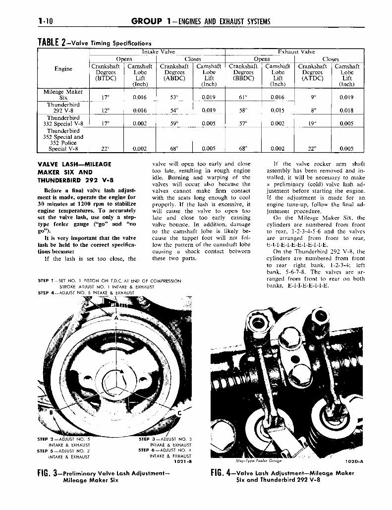
On the Thunderbird 332 and 352Special and the 352 Police SpecialV-8 remove the valve rocker armshaft assembly and install a solidtappet-type push rod in the push rodbore of the camshaft lobe to bechecked.
2. Make sure the push rod is inthe tappet socket or the lifter pushrod cup, then install a dial indicatorin such a manner as to have theactuating point of the indicator inthe push rod socket and in the sameplane as the push rod movement(Fig. 1 or 2).
3. Rotate the crankshaft slowlyin the direction of rotation untilthe tappet or lifter is on the basecircle of the camshaft lobe. At thispoint, the push rod will be in itslowest position. Zero the dial in-dicator, then continue to rotate thedamper slowly until the push rod isin the fully raised position. Com-pare the total lift recorded on theindicator with specifications.
Dial indicator
BE SURETO PLACE
INDICATOR TIPIN CENTEROF PUSH
RODSOCKET
4. Continue to rotate the crank-shaft until the indicator reads zero.This is a check on the accuracy ofthe original indicator reading.
VALVE TIMING
The valve timing should bechecked when poor engine perform-ance is noted and all other checks,such as carburetion, ignition tim-ing, etc. fail to locate the cause ofthe trouble.
Before the valve timing ischecked, check for a bent timingpointer. Bring the No. 1 piston toT.D.C. on the compression strokeand see if the timing pointer isaligned with the T.D.C. mark onthe damper.
If the valve timing is not withinspecifications, check the timingchain, camshaft sprocket, crank-shaft sprocket, camshaft, andcrankshaft in the order of acces-sibility.
To check the valve timing withthe engine installed, proceed asfollows:
1. Install a quadrant on thecrankshaft damper.
On the Mileage Maker Six andThunderbird 292 V-8, back off theNo. 1 intake valve adjusting screw,
then slide the rocker arm to oneside and secure it in this position.
On the Thunderbird 332 and 352Special and the 352 Police SpecialV-8, remove the right valve rockerarm shaft assembly and remove theNo. 1 intake valve push rod (thesecond push rod) and install a solidtappet-type push rod in its place.
2. Make sure the push rod is inthe tappet socket or the lifter pushrod cup, then install a dial indicatorin such a manner as to have theactuating point of the indicator inthe push rod socket and in the sameplane as the push rod movement(Fig. 1 or 2).
3. Rotate the crankshaft slowlyin the direction of rotation untilthe tappet or lifter is on the basecircle of the camshaft lobe. At thispoint the push rod will be in itslowest position. Zero the dial in-dicator and continue rotating thecrankshaft slowly in the directionof rotation until the dial indicatorregisters the specified camshaft lobelift (Table 2).
4. Compare the crankshaft de-grees indicated on the quadrantwith specifications (Table 2). Afterthe valve opening is checked, con-tinue to rotate the damper to checkthe valve closing.
1O26-B
BE SURE TO PLACEIndicator TIP IN CENTEROF PUSH ROD SOCKET
1748-B
FIG. 1-Camshaft Lobe Lift-Mileage Maker Sixor Thunderbird 292 V-8
FIG. 2—Camshaft Lobe Lift—Thunderbird 332 or352 Special and 352 Police Special V-8
MO G R O U P 1-ENGINES AND EXHAUST SYSTEMS
TABLE 2—Valve Timing Specifications
Engine
Mileage MakerSix
Thunderbird292 V-8
Thunderbird332 Special V-8
Thunderbird352 Special and
352 PoliceSpecial V-8
Intake ValveOpens
CrankshaftDegrees(BTDC)
17°
12°
17°
22°
CamshaftLobeLift
(Inch)
0.016
0.016
0.002
0.002
ClosesCrankshaft
Degrees(ABDC)
53°
54°
59°
68°
CamshaftLobeLift
(Inch)
0.019
0.019
0.005
0.005
Exhaust ValveOpens
CrankshaftDegrees(BBDC)
61°
58°
57°
68°
CamshaftLobeLift
(Inch)
0.016
0.015
0.002
0.002
ClosesCrankshaft
Degrees(ATDC)
9°
8°
19°
22°
CamshaftLobeLift
(Inch)
0.019
0.018
0.005
0.005
VALVE LASH—MILEAGEMAKER SIX ANDTHUNDERBIRD 292 V-8
Before a final valve lash adjust-ment is made, operate the engine for30 minutes at 1200 rpm to stabilizeengine temperatures. To accuratelyset the valve lash, use only a step-type feeler gauge ("go" and "nogo").
It is very important that the valvelash be held to the correct specifica-tions because:
If the lash is set too close, the
valve will open too early and closetoo late, resulting in rough engineidle. Burning and warping of thevalves will occur also because thevalves cannot make firm contactwith the seats long enough to coolproperly. If the lash is excessive, itwill cause the valve to open toolate and close too early causingvalve bounce. In addition, damageto the camshaft lobe is likely be-cause the tappet foot will not fol-low the pattern of the camshaft lobecausing a shock contact betweenthese two parts.
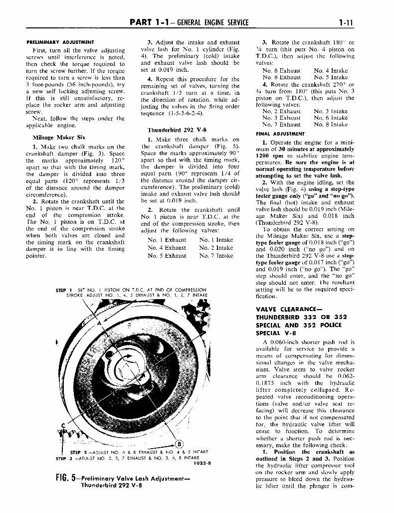
STEP 1 — SET NO. 1 PISTON ON T.D.C. AT END OF COMPRESSION
STROKE ADJUST NO. 1 INTAKE & EXHAUST
STEP 4 —ADJUST NO. 6 INTAKE & EXHAUST
If the valve rocker arm shaftassembly has been removed and in-stalled, it will be necessary to makea preliminary (cold) valve lash ad-justment before starting the engine.If the adjustment is made for anengine tune-up, follow the final ad-justment procedure.
On the Mileage Maker Six, thecylinders are numbered from frontto rear, 1-2-3-4-5-6 and the valvesare arranged from front to rear,E-I-I-E-I-E-E-I-E-I-I-E.
On the Thunderbird 292 V-8, thecylinders are numbered from frontto rear—right bank, 1-2-3-4; leftbank, 5-6-7-8. The valves are ar-ranged from front to rear on bothbanks, E-I-I-E-E-I-I-E.
STEP 2—ADJUST NO. 5
INTAKE & EXHAUST
STEP 5—ADJUST NO. 2
INTAKE & EXHAUST
STEP 3 - A D J U S T NO. 3
INTAKE & EXHAUSTSTEP 6 - A D J U S T NO. 4
INTAKE & EXHAUST1O21-B Step-Type Feeler Gauge TO2O-A
FIG. 3—Preliminary Valve Lash Adjustment-Mileage Maker Six
FIG. 4—Valve Lash Adjustment—Mileage MakerSix and Thunderbird 292 V-8
P A R T 1 - 1 - GENERAL ENGINE SERVICE M l
PRELIMINARY ADJUSTMENT
First, turn all the valve adjustingscrews until interference is noted,then check the torque required toturn the screw further. If the torquerequired to turn a screw is less than3 foot-pounds (36 inch-pounds), trya new self locking adjusting screw.If this is still unsatisfactory, re-place the rocker arm and adjustingscrew.
Next, follow the steps under theapplicable engine.
Mileage Maker Six1. Make two chalk marks on the
crankshaft damper (Fig. 3). Spacethe marks approximately 120°apart so that with the timing mark,the damper is divided into threeequal parts (120° represents 1/3of the distance around the dampercircumference).
2. Rotate the crankshaft until theNo. 1 piston is near T.D.C. at theend of the compression stroke.The No. 1 piston is on T.D.C. atthe end of the compression strokewhen both valves are closed andthe timing mark on the crankshaftdamper is in line with the timingpointer.
3. Adjust the intake and exhaustvalve lash for No. 1 cylinder (Fig.4). The preliminary (cold) intakeand exhaust valve lash should beset at 0.019 inch.
4. Repeat this procedure for theremaining set of valves, turning thecrankshaft 1/3 turn at a time, inthe direction of rotation, while ad-justing the valves in the firing ordersequence (1-5-3-6-2-4).
Thunderbird 292 V-81. Make three chalk marks on
the crankshaft damper (Fig. 5).Space the marks approximately 90°apart so that with the timing mark,the damper is divided into fourequal parts (90° represents 1/4 ofthe distance around the damper cir-cumference). The preliminary (cold)intake and exhaust valve lash shouldbe set at 0.019 inch.
2. Rotate the crankshaft untilNo. 1 piston is near T.D.C. at theend of the compression stroke, thenadjust the following valves:
No. 1 Exhaust No. 1 IntakeNo. 4 Exhaust No. 2 IntakeNo. 5 Exhaust No. 7 Intake
STEP 1 -SET NO. 1 PISTON ON T.D.C. AT END OF COMPRESSIONSTROKE-ADJUST NO. 1, 4, 5 EXHAUST & NO. 1, 2, 7 INTAKE
STEP 2 -ADJUST NO. 6 & 8 EXHAUST & NO. 4 & 5 INTAKE
STEP 3 -ADJUST NO. 2, 3, 7 EXHAUST & NO. 3, 6, 8 INTAKE
1O22-B
FIG. 5—Preliminary Valve Lash Adjustment—Thunderbird 292 V-8
3. Rotate the crankshaft 180° orV2 turn (this puts No. 4 piston onT.D.C), then adjust the followingvalves:
No. 6 Exhaust No. 4 IntakeNo. 8 Exhaust No. 5 Intake4. Rotate the crankshaft 270° or
3A turn from 180° (this puts No. 3piston on T.D.C), then adjust thefollowing valves:
No. 2 Exhaust No. 3 IntakeNo. 3 Exhaust No. 6 IntakeNo. 7 Exhaust No. 8 Intake
FINAL ADJUSTMENT
1. Operate the engine for a mini-mum of 30 minutes at approximately1200 rpm to stabilize engine tem-peratures. Be sure the engine is atnormal operating temperature beforeattempting to set the valve lash.
2. With the engine idling, set thevalve lash (Fig. 4) using a step-typefeeler gauge only ("go" and "no go").The final (hot) intake and exhaustvalve lash should be 0.019 inch (Mile-age Maker Six) and 0.018 inch(Thunderbird 292 V-8).
To obtain the correct setting onthe Mileage Maker Six, use a step-type feeler gauge of 0.018 inch ("go")and 0.020 inch ("no go") and onthe Thunderbird 292 V-8 use a step-type feeler gauge of 0.017 inch ("go")and 0.019 inch ("no go"). The "go"step should enter, and the "no go"step should not enter. The resultantsetting will be to the required speci-fication.
VALVE CLEARANCE—THUNDERBIRD 332 OR 352SPECIAL AND 352 POLICESPECIAL V-8
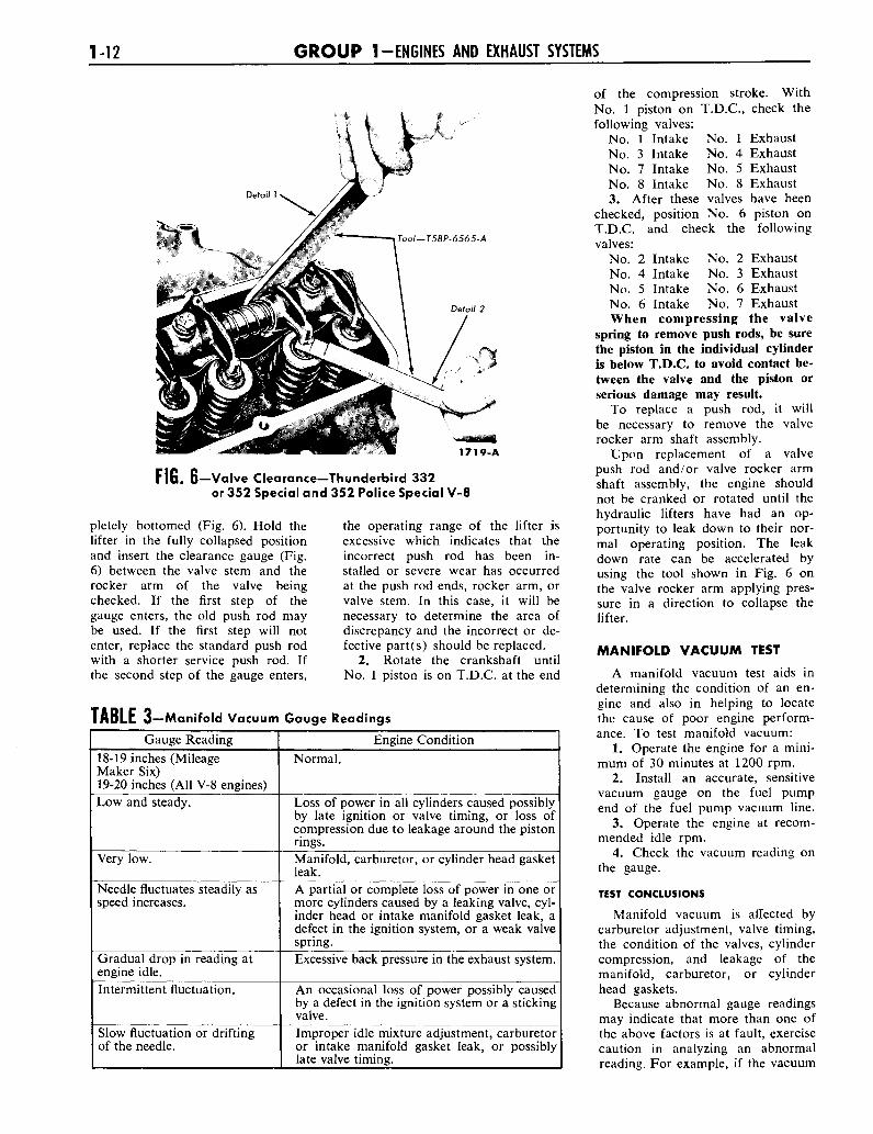
A 0.060-inch shorter push rod isavailable for service to provide ameans of compensating for dimen-sional changes in the valve mecha-nism. Valve stem to valve rockerarm clearance should be 0.062-0.1875 inch with the hydrauliclifter completely collapsed. Re-peated valve reconditioning opera-tions (valve and/or valve seat re-facing) will decrease this clearanceto the point that if not compensatedfor, the hydraulic valve lifter willcease to function. To determinewhether a shorter push rod is nec-essary, make the following check:
1. Position the crankshaft asoutlined in Steps 2 and 3. Positionthe hydraulic lifter compressor toolon the rocker arm and slowly applypressure to bleed down the hydrau-lic lifter until the plunger is com-
1-12 G R O U P 1-ENGINES AND EXHAUST SYSTEMS
L
1719-A
FIG. 6— Valve Clearance—Thunderbird 332or 352 Special and 352 Police Special V-8
pletely bottomed (Fig. 6). Hold thelifter in the fully collapsed positionand insert the clearance gauge (Fig.6) between the valve stem and therocker arm of the valve beingchecked. If the first step of thegauge enters, the old push rod maybe used. If the first step will notenter, replace the standard push rodwith a shorter service push rod. Ifthe second step of the gauge enters,
the operating range of the lifter isexcessive which indicates that theincorrect push rod has been in-stalled or severe wear has occurredat the push rod ends, rocker arm, orvalve stem. In this case, it will benecessary to determine the area ofdiscrepancy and the incorrect or de-fective part(s) should be replaced.
2. Rotate the crankshaft untilNo. 1 piston is on T.D.C. at the end
TABLE 3—Manifold Vacuum Gauge ReadingsGauge Reading
18-19 inches (MileageMaker Six)19-20 inches (All V-8 engines)Low and steady.
Very low.
Needle fluctuates steadily asspeed increases.
Gradual drop in reading atengine idle.Intermittent fluctuation.
Slow fluctuation or driftingof the needle.
Engine ConditionNormal.
Loss of power in all cylinders caused possiblyby late ignition or valve timing, or loss ofcompression due to leakage around the pistonrings.Manifold, carburetor, or cylinder head gasketleak.A partial or complete loss of power in one ormore cylinders caused by a leaking valve, cyl-inder head or intake manifold gasket leak, adefect in the ignition system, or a weak valvespring.Excessive back pressure in the exhaust system.
An occasional loss of power possibly causedby a defect in the ignition system or a stickingvalve.Improper idle mixture adjustment, carburetoror intake manifold gasket leak, or possiblylate valve timing.
of the compression stroke. WithNo. 1 piston on T.D.C, check thefollowing valves:
No. 1 Intake No. 1 ExhaustNo. 3 Intake No. 4 ExhaustNo. 7 Intake No. 5 ExhaustNo. 8 Intake No. 8 Exhaust3. After these valves have been
checked, position No. 6 piston onT.D.C. and check the followingvalves:
No. 2 IntakeNo. 4 IntakeNo. 5 IntakeNo. 6 Intake
No. 2 ExhaustNo. 3 ExhaustNo. 6 ExhaustNo. 7 Exhaust
When compressing the valvespring to remove push rods, be surethe piston in the individual cylinderis below T.D.C. to avoid contact be-tween the valve and the piston orserious damage may result.
To replace a push rod, it willbe necessary to remove the valverocker arm shaft assembly.
Upon replacement of a valvepush rod and/or valve rocker armshaft assembly, the engine shouldnot be cranked or rotated until thehydraulic lifters have had an op-portunity to leak down to their nor-mal operating position. The leakdown rate can be accelerated byusing the tool shown in Fig. 6 onthe valve rocker arm applying pres-sure in a direction to collapse thelifter.
MANIFOLD VACUUM TEST
A manifold vacuum test aids indetermining the condition of an en-gine and also in helping to locatethe cause of poor engine perform-ance. To test manifold vacuum:
1. Operate the engine for a mini-mum of 30 minutes at 1200 rpm.
2. Install an accurate, sensitivevacuum gauge on the fuel pumpend of the fuel pump vacuum line.
3. Operate the engine at recom-mended idle rpm.
4. Check the vacuum reading onthe gauge.
TEST CONCLUSIONS
Manifold vacuum is affected bycarburetor adjustment, valve timing,the condition of the valves, cylindercompression, and leakage of themanifold, carburetor, or cylinderhead gaskets.
Because abnormal gauge readingsmay indicate that more than one ofthe above factors is at fault, exercisecaution in analyzing an abnormalreading. For example, if the vacuum
P A R T 1-1 -GENERAL ENGINE SERVICE 1-13
is low, the correction of one itemmay increase the vacuum enough soas to indicate that the trouble hasbeen corrected. It is important,therefore, that each cause of an ab-normal reading be investigated andfurther tests conducted where nec-essary in order to arrive at the cor-rect diagnosis of the trouble.
Table 3 lists various types ofreadings and their possible causes.
Allowance should be made forthe effect of altitude on the gaugereading. The engine vacuum will de-crease with an increase in altitude.
COMPRESSION TEST
1. Be sure the battery is good.Operate the engine for a minimumof 30 minutes at 1200 rpm. Turn theignition switch off, then remove allthe spark plugs.
2. Set the throttle plates (primarythrottle plates only on the 4-barrelcarburetor) and the choke plate inthe wide open position.
3. Install a compression gauge inNo. 1 cylinder.
4. Crank the engine several timesand record the highest reading reg-istered. Note the number of com-pression strokes required to obtainthe highest reading.
5. Repeat the test on each cylin-der, cranking the engine the samenumber of times for each cylinderas was required to obtain the high-est reading on No. 1 cylinder.
TEST CONCLUSIONS
A variation of =+=20 pounds(Thunderbird 332 or 352 Specialand 352 Police Special V-8) or ±10pounds (Mileage Maker Six andThunderbird 292 V-8) from specifiedpressure is satisfactory. However, thecompression of all cylinders shouldbe uniform within 10 pounds.
A reading of more than the al-lowable tolerance above normal in-dicates excessive deposits in thecylinder.
A reading of more than the al-lowable tolerance below normal in-dicates leakage at the cylinder headgasket, piston rings, or valves.
A low even compression in twoadjacent cylinders indicates a cylin-der head gasket leak. This shouldbe checked before condemning therings or valves.
To determine whether the ringsor the valves are at fault, squirt theequivalent of a tablespoon of heavyoil into the combustion chamber,then crank the engine to distributethe oil and repeat the compressiontest. The oil will temporarily sealleakage past the rings. If approxi-mately the same reading is ob-tained, the rings are satisfactory,but the valves are leaking. If thecompression has increased 10pounds or more over the originalreading, there is leakage past therings.
During a compression test, if thepressure fails to climb steadily andremains the same during the firsttwo successive strokes, but climbshigher on the succeeding strokes, orfails to climb during the entire test,it indicates a sticking or stuckvalve.
CLEANING, INSPECTION, AND RECONDITIONING
INTAKE MANIFOLD
Clean the manifolds in a suitablesolvent, then dry them with com-pressed air. Scrape all carbon de-posits from the center exhaust pas-sage below the carburetor heatriser. This carbon acts as an insu-lator restricting the heating actionof the hot exhaust gases.
Inspect the manifold for cracks,leaks, or other defects that wouldmake it unfit for further service. Re-place all studs that are stripped orotherwise damaged. Remove all fil-ings and foreign matter that mayhave entered the manifold as a re-sult of repairs.
On the Thunderbird 292 V-8,blow out the automatic choke pas-sages of the intake manifold withcompressed air. Make sure the pas-sages are completely open, other-wise choke operation will be im-paired. Check the automatic chokeair heat tube that passes throughthe intake manifold for leaks, asfollows:
Adjust a vacuum pump to obtaina steady reading of three inches ofvacuum. Block off one opening ofthe tube with a moistened finger,then connect the vacuum pumphose to the other opening. If the
pump does not maintain a steadyreading there is a leak in the tubeand the tube should be replaced.
On the Thunderbird 332 or352 Special and the 352 Police Spe-cial V-8, check the baffle plate onthe underside of the manifold forlooseness and be sure the mazescreen is in place. Clean off any var-nish accumulation.
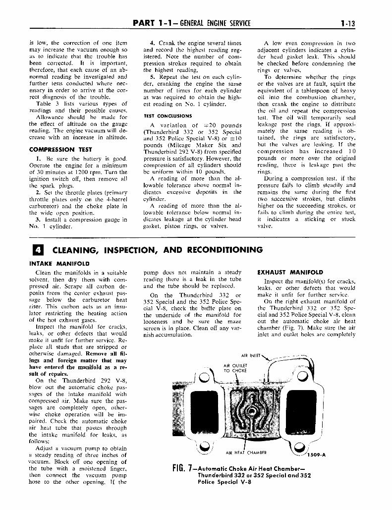
EXHAUST MANIFOLD
Inspect the manifold(s) for cracks,leaks, or other defects that wouldmake it unfit for further service.
On the right exhaust manifold ofthe Thunderbird 332 or 352 Spe-cial and 352 Police Special V-8, cleanout the automatic choke air heatchamber (Fig. 7). Make sure the airinlet and outlet holes are completely
AIR INLET'
1509-A
FIG. 7—Automatic Choke Air Heat Chamber—Thunderbird 332 or 352 Special and 352Police Special V-8

1-14 G R O U P 1-ENGINES AND EXHAUST SYSTEMS
Runout Gauge •
Holding fixture' PUSH ROD
FIG. 8—Push Rod Runout—Typical
1003-A
( I / w^ ^ A1735-A
0 (3) CHECK DIAGONALLY
( 2 ) CHECK ACROSS CENTER
FIG. 9—Cylinder Head Flatness—Typical
FIG. 10—Valve Seat Runout—Typical
1729-A
open and the cover does not leak.Blow out the automatic choke airheat tube with compressed air.
VALVE ROCKER ARMSHAFT ASSEMBLY
Clean all the parts thoroughly.Make sure that all oil passages areopen.
Check the clearance betweeneach rocker arm and the shaft bychecking the I.D. of the rockerarm bore and the O.D. of the shaft.If the clearance between any rockerarm and the shaft exceeds the wearlimit, replace the shaft and/or therocker arm. Inspect the shaft andthe rocker arm bore for nicks,scratches, scores, or scuffs. Dress upminor surface defects with a hone.
Inspect the pad at the valve endof the rocker arms for a groovedradius. If the pad is grooved, re-place the rocker arm. Do not at-tempt to true this surface by grind-ing.
Check for broken locatingsprings.
On the Mileage Maker Six andThunderbird 292 V-8, check therocker arm adjusting screws and thepush rod end of the rocker armsfor stripped or broken threads, andthe ball end of the adjusting screwfor nicks, scratches, or excessive
wear. Inspect the oil tubes forcracks or sharp bends.
PUSH RODS
Check the ends of the push rodsfor nicks, grooves, roughness, or ex-cessive wear.
The push rods can be visuallychecked for straightness while theyare installed in the engine by rotat-ing them with the valve closed.They also can be checked with adial indicator (Fig. 8). If the run-out exceeds the maximum limit atany point, discard the rod. Do notattempt to straighten push rods.
CYLINDER HEADS
CLEANING AND INSPECTION
With the valves installed to pro-tect the valve seats, remove depositsfrom the combustion chambers andvalve heads with a scraper and awire brush. Be careful not to scratchthe cylinder head gasket surface.After the valves are removed, cleanthe valve guide bores with a valveguide cleaning tool. Use cleaningsolvent to remove dirt, grease, andother deposits.
Check the cylinder head forcracks, and the gasket surface forburrs and nicks. Replace the headif it is cracked. Do not plane or
grind more than 0.010 inch fromthe cylinder head gasket surface.Remove all burrs or scratches withan oil stone.
CYLINDER HEAD FLATNESS
Check the flatness of the cylinderhead gasket surface (Fig. 9). Speci-fications for flatness are 0.006 inchmaximum overall, or 0.003 inch inany 6 inches.
VALVE SEAT RUNOUT
Check the valve seat runout withan accurate gauge (Fig. 10). Followthe instructions of the gauge manu-facturer. The total runout shouldnot exceed the wear limit.
VALVE SEAT WIDTH
Measure the valve seat width(Fig. 11). The intake valve seatwidth limits are 0.060-0.080 inchand the exhaust valve seat widthlimits are 0.070-0.090 inch.
REAMING VALVE GUIDES
If it becomes necessary to reama valve guide (Fig. 12) to install avalve with an oversize stem, a ream-ing kit is available which containsthe following reamer and pilot com-binations; a 0.003-inch O.S. reamerwith a standard diameter pilot, a0.015-inch O.S. reamer with a0.003-inch O.S. pilot, and a 0.030-inch reamer with a 0.015-inch O.S.pilot.
P A R T 1-1-GENERAL ENGINE SERVICE 1-15
Seat Width Scale
Tool-T58P-6085-B332 AND 352 SPECIAL V-8
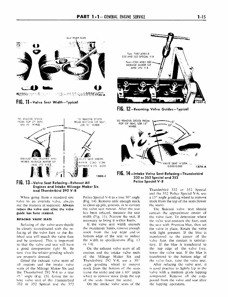
FIG. 11-Valve Seat Width-Typical
Tool-T52L-6085-AEEMILEAGE MAKER SIX
AND 292 V-8
1007-C
FIG. 12—Reaming Valve Guides—Typical
TO REMOVE STOCKFROM TOP OF SEAT,
USE 60° WHEEL
TO REMOVE STOCKFROM BOTTOM OF SEAT,
USE 30" WHEEL
TO REMOVE STOCK FROMTOP OF SEAT, USE 15°
WHEEL
EXHAUST ALL ENGINES ANDINTAKE MILEAGE MAKER SIX
AND 292 V-8 |
illVALVE SEAT WIDTH:
INTAKE 0.060—0.080
EXHAUST 0.070—0.090
• — - *
VALVE SEAT WIDTH:0.060-0.080
7 I \ I1578-A
1OO8-C
FIG. 13-Valve Seat Refacing-Exhaust AllEngines and Intake Mileage Maker Sixand Thunderbird 292 V-8
FIG. 14—Intake Valve Seat Refacing—Thunderbird332 or 352 Special and 352Police Special V-8
When going from a standard sizevalve to an oversize valve, alwaysuse the reamers in sequence. Alwaysreface the valve seat after the valveguide has been reamed.
REFACING VALVE SEATS
Refacing of the valve seats shouldbe closely co-ordinated with the re-facing of the valve face so the fin-ished seat will match the valve faceand be centered. This is importantso that the valve and seat will havea good compression tight fit. Besure that the refacer grinding wheelsare properly dressed.
Grind the exhaust valve seats ofall engines and the intake valveseats of the Mileage Maker Six andthe Thunderbird 292 V-8 to a true45° angle (Fig. 13). Grind the in-take valve seat of the Thunderbird332 or 352 Special and the 352
Police Special V-8 to a true 30° angle(Fig. 14). Remove only enough stockto clean up pits, grooves, or to correctthe valve seat runout. After the seathas been refaced, measure the seatwidth (Fig. 11). Narrow the seat, ifnecessary to bring it within limits.
If the valve seat width exceedsthe maximum limits, remove enoughstock from the top edge and orbottom edge of the seat to reducethe width to specifications (Fig. 13or 14).
On the exhaust valve seats of allengines and the intake valve seatsof the Mileage Maker Six andThunderbird 292 V-8, use a 30°angle grinding wheel to removestock from the bottom of the seats(raise the seats) and use a 60° anglewheel to remove stock from the topof the seats (lower the seats).
On the intake valve seats of the
Thunderbird 332 or 352 Specialand the 352 Police Special V-8, usea 15° angle grinding wheel to removestock from the top of the seats (lowerthe seats).
The finished valve seat shouldcontact the approximate center ofthe valve face. To determine wherethe valve seat contacts the face, coatthe seat with Prussian blue, then setthe valve in place. Rotate the valvewith light pressure. If the blue istransferred to the center of thevalve face, the contact is satisfac-tory. If the blue is transferred tothe top edge of the valve face,lower the valve seat. If the blue istransferred to the bottom edge ofthe valve face, raise the valve seat.
After refacing the valve seat, itis good practice to lightly lap in thevalve with a medium grade lappingcompound. Remove all the com-pound from the valve and seat afterthe lapping operation.
1-16 G R O U P 1-ENGINES AND EXHAUST SYSTEMS
MINIMUM
REFER TO SPECIFICATIONSFOR CORRECT DIAMETER
TCHECK FOR BENT STEM
Model TV-2 Runout Gauge
DO NOT REMOVE MORE THAN 0.010 INCH
45° EXHAUST, ALL ENGINES45° INTAKE, MILEAGE MAKER SIX AND 292 V-830° INTAKE, 332, 352 SPECIAL V-8 1 0 1 4 C
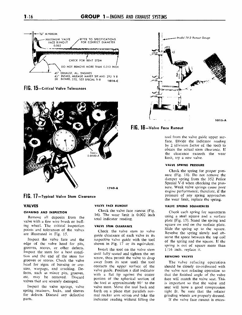
FIG. 15—Critical Valve Tolerances
1O15-A
FIG. 16—Valve Face Runout
1740-A
FIG. 17—Typical Valve Stem Clearance
VALVES
CLEANING AND INSPECTION
Remove all deposits from thevalve with a fine wire brush or buff-ing wheel. The critical inspectionpoints and tolerances of the valvesare illustrated in Fig. 15.
Inspect the valve face and theedge of the valve head for pits,grooves, scores, or other defects.Inspect the stem for a bent condi-tion and the end of the stem forgrooves or scores. Check the valvehead for signs of burning or ero-sion, warpage, and cracking. De-fects, such as minor pits, grooves,etc. may be removed. Discardvalves that are severely damaged.
Inspect the valve springs, valvespring retainers, locks, and sleevesfor defects. Discard any defectiveparts.
VALVE FACE RUNOUT
Check the valve face runout (Fig.16). The wear limit is 0.002 inchtotal indicator reading.
VALVE STEM CLEARANCE
Check the valve stem to valveguide clearance of each valve in itsrespective valve guide with the toolshown in Fig. 17 or its equivalent.
Install the tool on the valve stemuntil fully seated and tighten the setscrew, then permit the valve to dropaway from its seat until the toolcontacts the upper surface of thevalve guide. Position a dial indicatorwith a flat tip against the centerportion of the spherical section ofthe tool at approximately 90° to thevalve stem. Move the tool back andforth on a plane that parallels nor-mal rocker arm action and take theindicator reading without lifting the
tool from the valve guide upper sur-face. Divide the indicator readingby 2 (division factor of the tool) toobtain the actual stem clearance. Ifthe clearance exceeds the wearlimit, try a new valve.
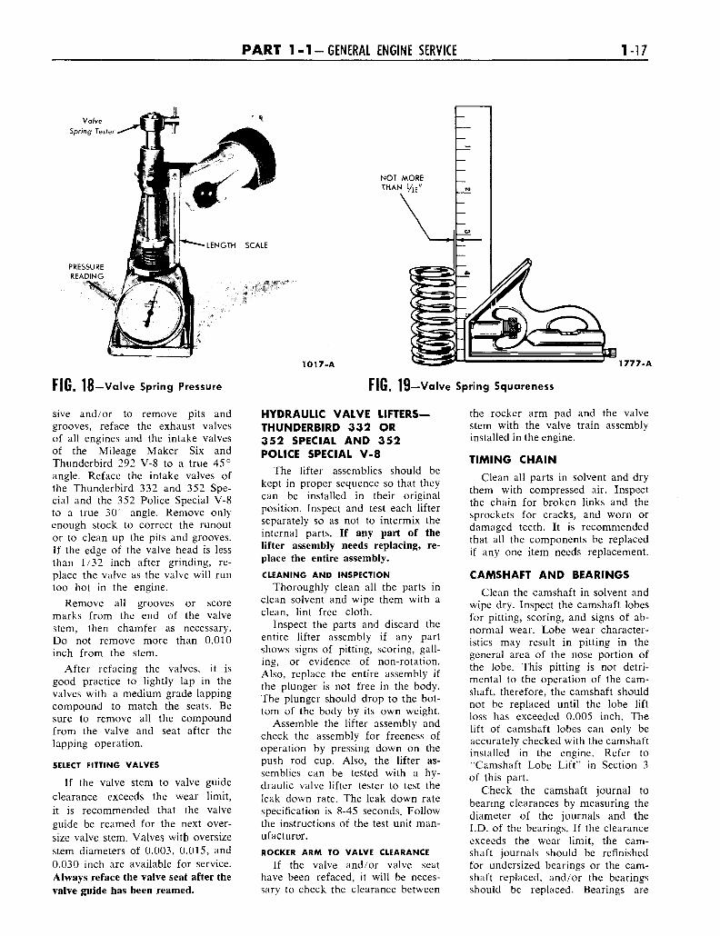
VALVE SPRING PRESSURE
Check the spring for proper pres-sure (Fig. 18). Do not remove thedamper spring from the 352 PoliceSpecial V-8 when checking the pres-sure. Weak valve springs cause poorengine performance; therefore, if thepressure of any spring approachesthe wear limit, replace the spring.
VALVE SPRING SQUARENESS
Check each spring for squarenessusing a steel square and a surfaceplate (Fig. 19). Stand the spring andsquare on end on the surface plate.Slide the spring up to the square.Revolve the spring slowly and ob-serve the space between the top coilof the spring and the square. If thespring is out of square more than1/16 inch, replace it.
REFACING VALVES
The valve refacing operationshould be closely co-ordinated withthe valve seat refacing operation sothat the finished angle of the valveface will match the valve seat. Thisis important so that the valve andseat will have a good compressiontight fit. Be sure that the refacergrinding wheels are properly dressed.
If the valve face runout is exces-
P A R T 1-1-GENERAL ENGINE SERVICE 1-17
ValveSpring Tester
PRESSUREREADING
NOT MORETHAN 1/16"
FIG. 18— Valve Spring Pressure
sive and/or to remove pits andgrooves, reface the exhaust valvesof all engines and the intake valvesof the Mileage Maker Six andThunderbird 292 V-8 to a true 45°angle. Reface the intake valves ofthe Thunderbird 332 and 352 Spe-cial and the 352 Police Special V-8to a true 30° angle. Remove onlyenough stock to correct the runoutor to clean up the pits and grooves.If the edge of the valve head is lessthan 1/32 inch after grinding, re-place the valve as the valve will runtoo hot in the engine.
Remove all grooves or scoremarks from the end of the valvestem, then chamfer as necessary.Do not remove more than 0.010inch from the stem.
After refacing the valves, it isgood practice to lightly lap in thevalves with a medium grade lappingcompound to match the seats. Besure to remove all the compoundfrom the valve and seat after thelapping operation.
SELECT FITTING VALVES
If the valve stem to valve guideclearance exceeds the wear limit,it is recommended that the valveguide be reamed for the next over-size valve stem. Valves with oversizestem diameters of 0.003, 0.015, and0.030 inch are available for service.Always reface the valve seat after thevalve guide has been reamed.
1017-A 1777-A
FIG. 19—Valve Spring Squareness
HYDRAULIC VALVE LIFTERS—THUNDERBIRD 332 OR352 SPECIAL AND 352POLICE SPECIAL V-8
The lifter assemblies should bekept in proper sequence so that theycan be installed in their originalposition. Inspect and test each lifterseparately so as not to intermix theinternal parts. If any part of thelifter assembly needs replacing, re-place the entire assembly.
CLEANING AND INSPECTION
Thoroughly clean all the parts inclean solvent and wipe them with aclean, lint free cloth.
Inspect the parts and discard theentire lifter assembly if any partshows signs of pitting, scoring, gall-ing, or evidence of non-rotation.Also, replace the entire assembly ifthe plunger is not free in the body.The plunger should drop to the bot-tom of the body by its own weight.
Assemble the lifter assembly andcheck the assembly for freeness ofoperation by pressing down on thepush rod cup. Also, the lifter as-semblies can be tested with a hy-draulic valve lifter tester to test theleak down rate. The leak down ratespecification is 8-45 seconds. Followthe instructions of the test unit man-ufacturer.ROCKER ARM TO VALVE CLEARANCE
If the valve and/or valve seathave been refaced, it will be neces-sarv to check the clearance between
the rocker arm pad and the valvestem with the valve train assemblyinstalled in the engine.
TIMING CHAINClean all parts in solvent and dry
them with compressed air. Inspectthe chain for broken links and thesprockets for cracks, and worn ordamaged teeth. It is recommendedthat all the components be replacedif any one item needs replacement.
CAMSHAFT AND BEARINGS
Clean the camshaft in solvent andwipe dry. Inspect the camshaft lobesfor pitting, scoring, and signs of ab-normal wear. Lobe wear character-istics may result in pitting in thegeneral area of the nose portion ofthe lobe. This pitting is not detri-mental to the operation of the cam-shaft, therefore, the camshaft shouldnot be replaced until the lobe liftloss has exceeded 0.005 inch. Thelift of camshaft lobes can only beaccurately checked with the camshaftinstalled in the engine. Refer to''Camshaft Lobe Lift" in Section 3of this part.
Check the camshaft journal tobearing clearances by measuring thediameter of the journals and theI.D. of the bearings. If the clearanceexceeds the wear limit, the cam-shaft journals should be refinishedfor undersized bearings or the cam-shaft replaced, and/or the bearingsshould be replaced. Bearings are
1-18 G R O U P 1-ENGINES AND EXHAUST SYSTEMS
available prefinished to size forstandard and 0.015-inch undersizejournal diameters.
Check the distributor drive gearfor broken or chipped teeth.
Remove light scuffs, scores, ornicks from the camshaft machinedsurfaces with a smooth oilstone.
CRANKSHAFTCLEANING AND INSPECTION
Handle the crankshaft with careto avoid possible fractures or dam-age to the finished surfaces. Cleanthe crankshaft with solvent, thenblow out all oil passages with com-pressed air.
Inspect main and connecting rodjournals for cracks, scratches,grooves, or scores. Dress minor im-perfections with an oilstone. Refin-ish severely marred journals.
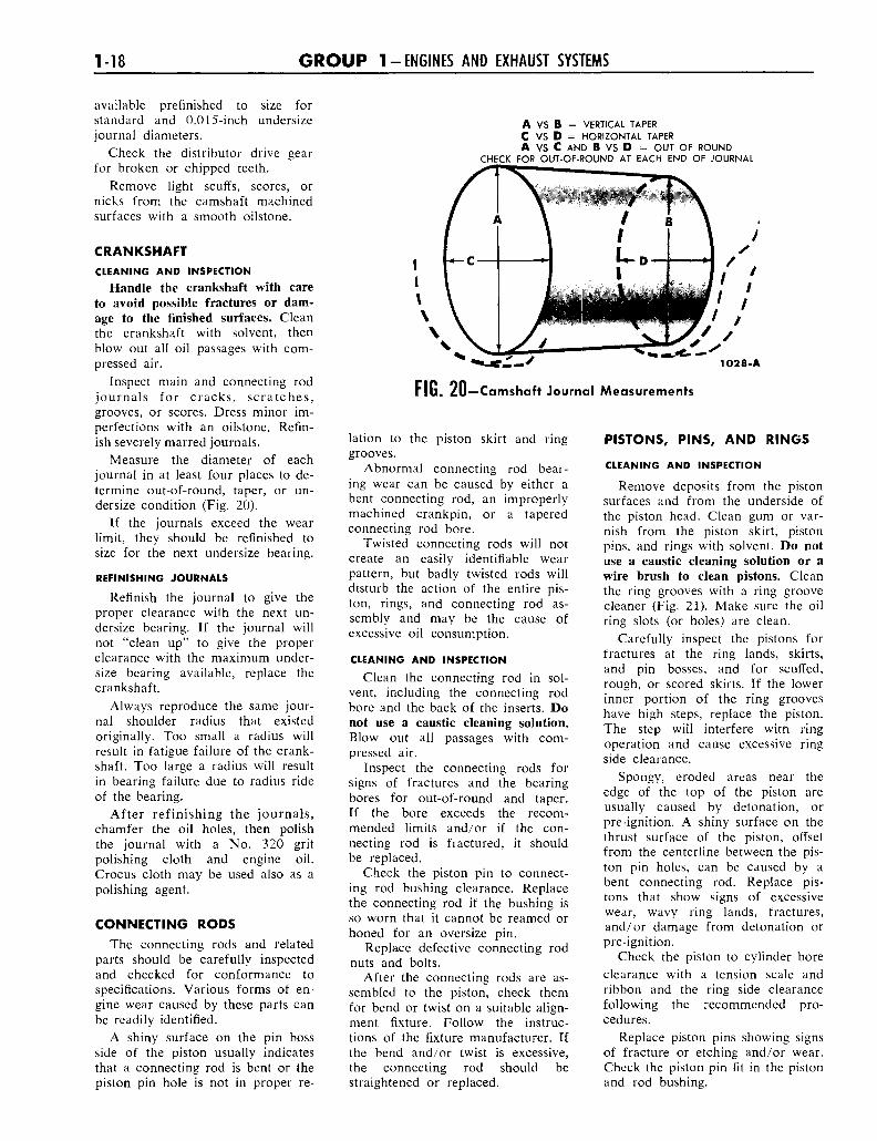
Measure the diameter of eachjournal in at least four places to de-termine out-of-round, taper, or un-dersize condition (Fig. 20).
If the journals exceed the wearlimit, they should be refinished tosize for the next undersize bearing.
REFINISHING JOURNALS
Refinish the journal to give theproper clearance with the next un-dersize bearing. If the journal willnot "clean up" to give the properclearance with the maximum under-size bearing available, replace thecrankshaft.
Always reproduce the same jour-nal shoulder radius that existedoriginally. Too small a radius willresult in fatigue failure of the crank-shaft. Too large a radius will resultin bearing failure due to radius rideof the bearing.
After refinishing the journals,chamfer the oil holes, then polishthe journal with a No. 320 gritpolishing cloth and engine oil.Crocus cloth may be used also as apolishing agent.
CONNECTING RODSThe connecting rods and related
parts should be carefully inspectedand checked for conformance tospecifications. Various forms of en-gine wear caused by these parts canbe readily identified.
A shiny surface on the pin bossside of the piston usually indicatesthat a connecting rod is bent or thepiston pin hole is not in proper re-
A VS B = VERTICAL TAPERC V S D = HORIZONTAL TAPERA VS C AND B VS D = OUT OF ROUND
CHECK FOR OUT-OF-ROUND AT EACH END OF JOURNAL
102 8-A
FIG. 20—Camshaft Journal Measurements
lation to the piston skirt and ringgrooves.
Abnormal connecting rod bear-ing wear can be caused by either abent connecting rod, an improperlymachined crankpin, or a taperedconnecting rod bore.
Twisted connecting rods will notcreate an easily identifiable wearpattern, but badly twisted rods willdisturb the action of the entire pis-ton, rings, and connecting rod as-sembly and may be the cause ofexcessive oil consumption.
CLEANING AND INSPECTION
Clean the connecting rod in sol-vent, including the connecting rodbore and the back of the inserts. Donot use a caustic cleaning solution.Blow out all passages with com-pressed air.
Inspect the connecting rods forsigns of fractures and the bearingbores for out-of-round and taper.If the bore exceeds the recom-mended limits and/or if the con-necting rod is fractured, it shouldbe replaced.
Check the piston pin to connect-ing rod bushing clearance. Replacethe connecting rod if the bushing isso worn that it cannot be reamed orhoned for an oversize pin.
Replace defective connecting rodnuts and bolts.
After the connecting rods are as-sembled to the piston, check themfor bend or twist on a suitable align-ment fixture. Follow the instruc-tions of the fixture manufacturer. Ifthe bend and/or twist is excessive,the connecting rod should bestraightened or replaced.
PISTONS, PINS, AND RINGS
CLEANING AND INSPECTION
Remove deposits from the pistonsurfaces and from the underside ofthe piston head. Clean gum or var-nish from the piston skirt, pistonpins, and rings with solvent. Do notuse a caustic cleaning solution or awire brush to clean pistons. Cleanthe ring grooves with a ring groovecleaner (Fig. 21). Make sure the oilring slots (or holes) are clean.
Carefully inspect the pistons forfractures at the ring lands, skirts,and pin bosses, and for scuffed,rough, or scored skirts. If the lowerinner portion of the ring grooveshave high steps, replace the piston.The step will interfere with ringoperation and cause excessive ringside clearance.
Spongy, eroded areas near theedge of the top of the piston areusually caused by detonation, orpre-ignition. A shiny surface on thethrust surface of the piston, offsetfrom the centerline between the pis-ton pin holes, can be caused by abent connecting rod. Replace pis-tons that show signs of excessivewear, wavy ring lands, fractures,and/or damage from detonation orpre-ignition.
Check the piston to cylinder boreclearance with a tension scale andribbon and the ring side clearancefollowing the recommended pro-cedures.
Replace piston pins showing signsof fracture or etching and/or wear.Check the piston pin fit in the pistonand rod bushing.
P A R T 1-1-GENERAL ENGINE SERVICE 1-19
Tool-RC-500
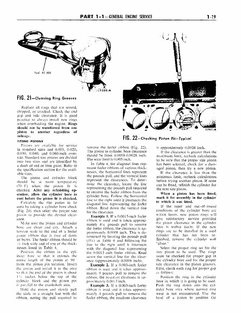
FIG. 21—Cleaning Ring Grooves
Replace all rings that are scored,chipped, or cracked. Check the endgap and side clearance. It is goodpractice to always install new ringswhen overhauling the engine. Ringsshould not be transferred from onepiston to another regardless ofmileage.FITTING PISTONS
Pistons are available for servicein standard sizes and 0.003, 0.020,0.030, 0.040, and 0.060-inch over-size. Standard size pistons are dividedinto two sizes and are identified bya daub of red or blue paint. Refer tothe specification section for the avail-able sizes.
The piston and cylinder blockshould be at room temperature(70 F) when the piston fit ischecked. After any refinishing op-eration, allow the cylinder bore tocool before the piston fit is checked.
Calculate the size piston to beused by taking a cylinder bore check(Fig. 28), then select the proper sizepiston to provide the desired clear-ance.
Make sure the piston and cylinderbore are clean and dry. Attach atension scale to the end of a feelergauge ribbon that is free of dentsor burrs. The feeler ribbon should beV2 inch wide and of one of the thick-nesses listed in Table 4.
Position the ribbon in the cyl-inder bore so that it extends theentire length of the piston at 90from the piston pin location. Invertthe piston and install it in the boreso that the end of the piston is about1 V*. inches below the top of thecylinder block and the piston pinis parallel to the crankshaft axis.
Hold the piston and slowly pullthe scale in a straight line with theribbon, noting the pull required to
1535-A
1741-A
FIG. 22 —Checking Piston Fit—Typical
remove the feeler ribbon (Fig. 22).The piston to cylinder bore clearanceshould be from 0.0008-0.0026 inch.The wear limit is 0.005 inch.
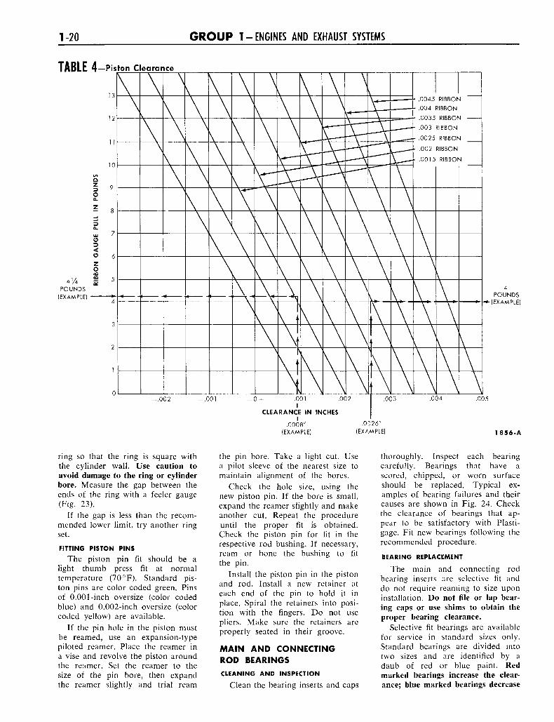
In Table 4, the diagonal lines rep-resent feeler ribbons of various thick-nesses, the horizontal lines representthe pounds pull, and the vertical linesrepresent the clearances. To deter-mine the clearance, locate the linerepresenting the pounds pull requiredto remove the feeler ribbon from thecylinder bore. Follow the horizontalline to the right until it intersects thediagonal line representing the feelerribbon. Read down the vertical linefor the clearance.
Example 1. If a 0.0015-inch feelerribbon is used and it takes approxi-mately 414 pounds pull to removethe feeler ribbon, the clearance is ap-proximately 0.0008 inch. This is de-termined by locating the pounds pull(414) in Table 4 and following theline to the right until it intersectswith the diagonal line representingthe 0.0015-inch feeler ribbon. Readdown the vertical line for the clear-ance (approximately 0.0008 inch).
Example 2. If a 0.003-inch feelerribbon is used and it takes approxi-mately 9 pounds pull to remove theribbon, the resultant clearance is ap-proximately 0.0015 inch.
Example 3. If a 0.003-inch feelerribbon is used and it takes approxi-mately 4 pounds pull to remove thefeeler ribbon, the resultant clearance
is approximately 0.0026 inch.If the clearance is greater than the
maximum limit, recheck calculationsto be sure that the proper size pistonhas been selected, check for a dam-aged piston, then try a new piston.
If the clearance is less than theminimum limit, recheck calculationsbefore trying another piston. If nonecan be fitted, refinish the cylinder forthe next size piston.
When a piston has been fitted,mark it for assembly in the cylinderto which it was fitted.
If the taper and out-of-roundconditions of the cylinder bore arewithin limits, new piston rings willgive satisfactory service providedthe piston clearance in the cylinderbore is within limits. If the newrings are to be installed in a usedcylinder that has not been re-finished, remove the cylinder wall"glaze."
Select the proper ring set for thesize piston to be used. The ringsmust be checked for proper gap inthe cylinder bore and for the properside clearance in the piston grooves.First, check each ring for proper gapas follows:
Position the ring in the cylinderbore in which it is going to be used.Push the ring down into the cyl-inder bore area where normal ringwear is not encountered. Use thehead of a piston to position the
1-20 G R O U P 1 - ENGINES AND EXHAUST SYSTEMS
TABLE 4-Piston Clearance
4 ' / 4
POUNDS(EXAMPLE)
13.0045 RIBBON
.004 RIBBON
.0035 RIBBON
.003 RIBBON
.0025 RIBBON
.002 RIBBON
.0015 RIBBON
POUNDS(EXAMPLE)
- . 0 0 2 -.001 .001I
CLEARANCE IN INCHESI
.0008"(EXAMPLE)
.005
.0026"(EXAMPLE) 1856-A
ring so that the ring is square withthe cylinder wall. Use caution toavoid damage to the ring or cylinderbore. Measure the gap between theends of the ring with a feeler gauge(Fig. 23).
If the gap is less than the recom-mended lower limit, try another ringset.
FITTING PISTON PINS
The piston pin fit should be alight thumb press fit at normaltemperature (70°F). Standard pis-ton pins are color coded green. Pinsof 0.001-inch oversize (color codedblue) and 0.002-inch oversize (colorcoded yellow) are available.
If the pin hole in the piston mustbe reamed, use an expansion-typepiloted reamer. Place the reamer ina vise and revolve the piston aroundthe reamer. Set the reamer to thesize of the pin bore, then expandthe reamer slightly and trial ream
the pin bore. Take a light cut. Usea pilot sleeve of the nearest size tomaintain alignment of the bores.
Check the hole size, using thenew piston pin. If the bore is small,expand the reamer slightly and makeanother cut. Repeat the procedureuntil the proper fit is obtained.Check the piston pin for fit in therespective rod bushing. If necessary,ream or hone the bushing to fitthe pin.
Install the piston pin in the pistonand rod. Install a new retainer ateach end of the pin to hold it inplace. Spiral the retainers into posi-tion with the fingers. Do not usepliers. Make sure the retainers areproperly seated in their groove.
MAIN AND CONNECTINGROD BEARINGSCLEANING AND INSPECTION
Clean the bearing inserts and caps
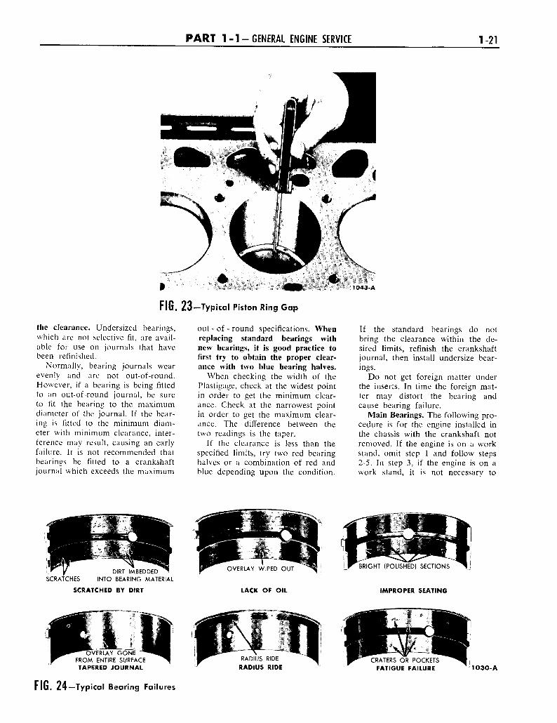
thoroughly. Inspect each bearingcarefully. Bearings that have ascored, chipped, or worn surfaceshould be replaced. Typical ex-amples of bearing failures and theircauses are shown in Fig. 24. Checkthe clearance of bearings that ap-pear to be satisfactory with Plasti-gage. Fit new bearings following therecommended procedure.
BEARING REPLACEMENT
The main and connecting rodbearing inserts are selective fit anddo not require reaming to size uponinstallation. Do not file or lap bear-ing caps or use shims to obtain theproper bearing clearance.
Selective fit bearings are availablefor service in standard sizes only.Standard bearings are divided intotwo sizes and are identified by adaub of red or blue paint. Redmarked bearings increase the clear-ance; blue marked bearings decrease
P A R T 1-1-GENERAL ENGINE SERVICE 1-21
1043-A
FIG. 23— Typical Piston Ring Gap
the clearance. Undersized bearings,which are not selective fit, are avail-able for use on journals that havebeen refinished.
Normally, bearing journals wearevenly and are not out-of-round.However, if a bearing is being fittedto an out-of-round journal, be sureto fit the bearing to the maximumdiameter of the journal. If the bear-ing is fitted to the minimum diam-eter with minimum clearance, inter-ference may result, causing an earlyfailure. It is not recommended thatbearings be fitted to a crankshaftjournal which exceeds the maximum
out - of - round specifications. Whenreplacing standard bearings withnew bearings, it is good practice tofirst try to obtain the proper clear-ance with two blue bearing halves.
When checking the width of thePlastigage, check at the widest pointin order to get the minimum clear-ance. Check at the narrowest pointin order to get the maximum clear-ance. The difference between thetwo readings is the taper.
If the clearance is less than thespecified limits, try two red bearinghalves or a combination of red andblue depending upon the condition.
If the standard bearings do notbring the clearance within the de-sired limits, refinish the crankshaftjournal, then install undersize bear-ings.
Do not get foreign matter underthe inserts. In time the foreign mat-ter may distort the bearing andcause bearing failure.
Main Bearings. The following pro-cedure is for the engine installed inthe chassis with the crankshaft notremoved. If the engine is on a workstand, omit step 1 and follow steps2-5. In step 3, if the engine is on awork stand, it is not necessary to
DIRT IMBEDDEDINTO BEARING MATERIALSCRATCHES
SCRATCHED BY DIRT
OVERLAY WIPED OUT
LACK OF OIL
BRIGHT (POLISHED) SECTIONS
IMPROPER SEATING
)VERLAY GONEFROM ENTIRE SURFACETAPERED JOURNAL
FIG. 24— Typical Bearing Failures
RADIUS RIDE
RADIUS RIDECRATERS OR POCKETS
FATIGUE FAILURE 1030-A
1-22 G R O U P 1-ENGINES AND EXHAUST SYSTEMS
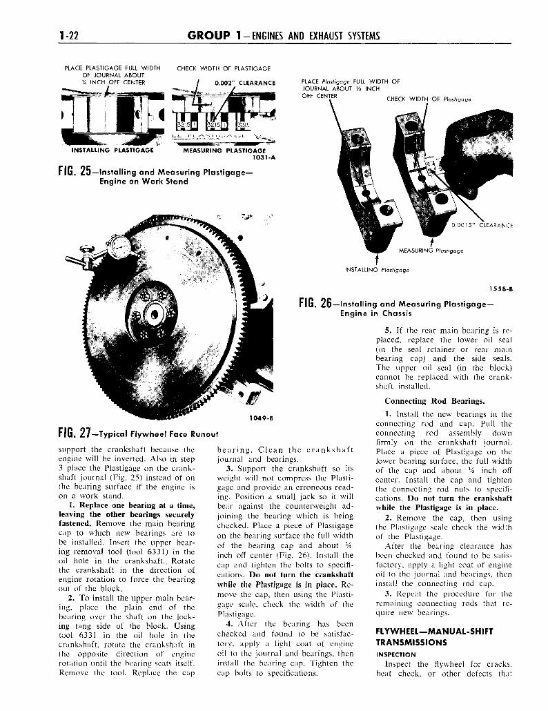
PLACE PLASTIGAGE FULL WIDTHOF JOURNAL ABOUTVA INCH OFF CENTER
CHECK WIDTH OF PLASTIGAGE
0.002 ' CLEARANCE PLACE Plastigage FULL WIDTH OFJOURNAL ABOUT VA INCHOFF CENTER CHECK WIDTH OF Plastigage
INSTALLING PLASTIGAGE MEASURING PLASTIGAGE1031-A
FIG. 25—Installing and Measuring Plastigage—Engine on Work Stand
0015 " CLEARANCE
MEASURING Plastigage
INSTALLING Plastigage
1558-B
1049-B
FIG. 27—Typical Flywheel Face Runout
support the crankshaft because theengine will be inverted. Also in step3 place the Plastigage on the crank-shaft journal (Fig. 25) instead of onthe bearing surface if the engine ison a work stand.
1. Replace one bearing at a time,leaving the other bearings securelyfastened. Remove the main bearingcap to which new bearings are tobe installed. Insert the upper bear-ing removal tool (tool 6331) in theoil hole in the crankshaft., Rotatethe crankshaft in the direction ofengine rotation to force the bearingout of the block.
2. To install the upper main bear-ing, place the plain end of thebearing over the shaft on the lock-ing tang side of the block. Usingtool 6331 in the oil hole in thecrankshaft, rotate the crankshaft inthe opposite direction of enginerotation until the bearing seats itself.Remove the tool. Replace the cap
bearing. Clean the crankshaftjournal and bearings.
3. Support the crankshaft so itsweight will not compress the Plasti-gage and provide an erroneous read-ing. Position a small jack so it willbear against the counterweight ad-joining the bearing which is beingchecked. Place a piece of Plastigageon the bearing surface the full widthof the bearing cap and about */4inch off center (Fig. 26). Install thecap and tighten the bolts to specifi-cations. Do not turn the crankshaftwhile the Plastigage is in place. Re-move the cap, then using the Plasti-gage scale, check the width of thePlastigage.
4. After the bearing has beenchecked and found to be satisfac-tory, apply a light coat of engineoil to the journal and bearings, theninstall the bearing cap. Tighten thecap bolts to specifications.
Flu. 26—Installing and Measuring Plastigage—Engine in Chassis
5. If the rear main bearing is re-placed, replace the lower oil seal(in the seal retainer or rear mainbearing cap) and the side seals.The upper oil seal (in the block)cannot be replaced with the crank-shaft installed.
Connecting Rod Bearings.1. Install the new bearings in the
connecting rod and cap. Pull theconnecting rod assembly downfirmly on the crankshaft journal.Place a piece of Plastigage on thelower bearing surface, the full widthof the cap and about XA inch offcenter. Install the cap and tightenthe connecting rod nuts to specifi-cations. Do not turn the crankshaftwhile the Plastigage is in place.
2. Remove the cap, then usingthe Plastigage scale check the widthof the Plastigage.
After the bearing clearance hasbeen checked and found to be satis-factory, apply a light coat of engineoil to the journal and bearings, theninstall the connecting rod cap.
3. Repeat the procedure for theremaining connecting rods that re-quire new bearings.
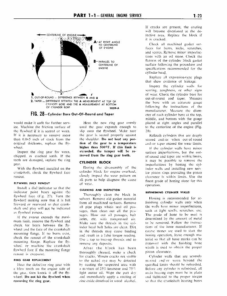
FLYWHEEL—MANUAL-SHIFTTRANSMISSIONSINSPECTION
Inspect the flywheel for cracks,heat check, or other defects that
P A R T 1-1-GENERAL ENGINE SERVICE 1-23
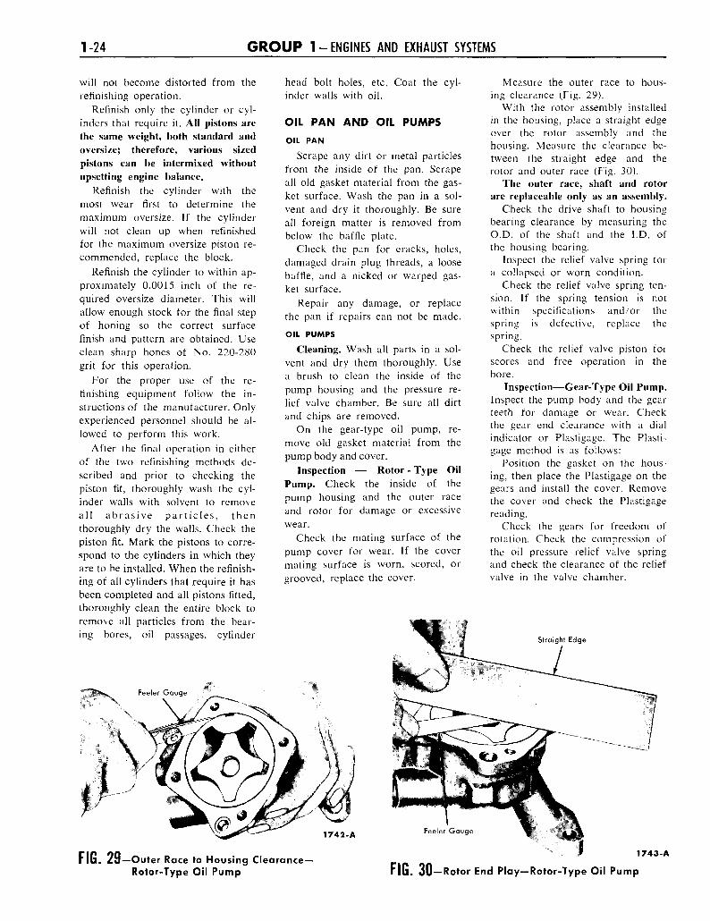
CENTERLIN£_OF ENGINE'A , . '••; -r'^K
A - A T RIGHT ANGLETO CENTERLINEOF ENGINE
B ~ PARALLEL TOCENTERLINE OFENGINE
h A1. OUT-OF-ROUND = DIFFERENCE BETWEEN A AND B
2 . TAPER = DIFFERENCE BETWEEN THE A MEASUREMENT AT TOP OFCYLINDER BORE AND THE A MEASUREMENT AT BOTTOMOF CYLINDER BORE 1039-A
FIG. 28—Cylinder Bore Out-Of-Round and Taper
would make it unfit for further serv-ice. Machine the friction surface ofthe flywheel if it is scored or worn.If it is necessary to remove morethan 0.045 inch of stock from theoriginal thickness, replace the fly-wheel.
Inspect the ring gear for worn,chipped, or cracked teeth. If theteeth are damaged, replace the ringgear.
With the flywheel installed on thecrankshaft, check the flywheel facerunout.
FLYWHEEL FACE RUNOUT
Install a dial indicator so that theindicator point bears against theflywheel face (Fig. 27). Turn theflywheel making sure that it is fullforward or rearward so that crank-shaft end play will not be indicatedas flywheel runout.
If the runout exceeds the maxi-mum limit, remove the flywheel andcheck for burrs between the fly-wheel and the face of the crankshaftmounting flange. If no burrs exist,check the runout of the crankshaftmounting flange. Replace the fly-wheel or machine the crankshaftflywheel face if the mounting flangerunout is excessive.
RING GEAR REPLACEMENT
Heat the defective ring gear witha blow torch on the engine side ofthe gear, then knock it off the fly-wheel. Do not hit the flywheel whenremoving the ring gear.
Heat the new ring gear evenlyuntil the gear expands enough toslip onto the flywheel. Make surethe gear is seated properly againstthe shoulder. Do not heat any por-tion of the gear to a temperaturehigher than 500°F. If this limit isexceeded, the temper will be re-moved from the ring gear teeth.
CYLINDER BLOCK
During the disassembly of thecylinder block for engine overhaul,closely inspect the wear pattern onall parts to help diagnose the causeof wear.
CLEANING AND INSPECTION
Thoroughly clean the block insolvent. Remove old gasket materialfrom all machined surfaces. Removeall pipe plugs which seal oil pas-sages, then clean out all the pas-sages. Blow out all passages, boltholes, etc. with compressed air.Make sure the threads in the cyl-inder head bolt holes are clean. Dirtin the threads may cause bindingand result in a false torque reading.Use a tap to true-up threads and toremove any deposits.
After the block has beenthoroughly cleaned, make a checkfor cracks. Minute cracks not visibleto the naked eye may be detectedby coating the suspected area witha mixture of 25% kerosene and 75%light motor oil. Wipe the part dryand immediately apply a coating ofzinc oxide dissolved in wood alcohol.
If cracks are present, the coatingwill become discolored at the de-fective area. Replace the block ifit is cracked.
Check all machined gasket sur-faces for burrs, nicks, scratches,and scores. Remove minor imperfec-tions with an oil stone. Check theflatness of the cylinder block gasketsurface following the procedure andspecifications recommended for thecylinder head.
Replace all expansion-type plugsthat show evidence of leakage.
Inspect the cylinder walls forscoring, roughness, or other signsof wear. Check the cylinder bore forout-of-round and taper. Measurethe bore with an accurate gaugefollowing the instructions of themanufacturer. Measure the diam-eter of each cylinder bore at the top,middle, and bottom with the gaugeplaced at right angles and parallelto the centerline of the engine (Fig.28).
Refinish cylinders that are deeplyscored and/or when out-of-roundand/or taper exceed the wear limits.
If the cylinder walls have minorsurface imperfections, but the out-of-round and taper are within limits,it may be possible to remove theimperfections by honing the cyl-inder walls and installing new serv-ice piston rings providing the pistonclearance is within limits. Use thefinest grade of honing stone for thisoperation.
REFINISHING CYLINDER WALLS
Honing is recommended for re-finishing cylinder walls only whenthe walls have minor imperfections,such as light scuffs, scratches, etc.The grade of hone to be used isdetermined by the amount of metalto be removed. Follow the instruc-tions of the hone manufacturer. Ifcoarse stones are used to start thehoning operation, leave enough ma-terial so that all hone marks can beremoved with the finishing honewhich is used to obtain the properpiston clearance.
Cylinder walls that are severelymarred and or worn beyond thespecified limits should be refinished.Before any cylinder is refinished, allmain bearing caps must be in placeand tightened to the proper torqueso that the crankshaft bearing bores
1-24 G R O U P 1 - ENGINES AND EXHAUST SYSTEMS
will not become distorted from therefinishing operation.
Refinish only the cylinder or cyl-inders that require it. AH pistons arethe same weight, both standard andoversize; therefore, various sizedpistons can be intermixed withoutupsetting engine balance.
Refinish the cylinder with themost wear first to determine themaximum oversize. If the cylinderwill not clean up when reflnishedfor the maximum oversize piston re-commended, replace the block.
Refinish the cylinder to within ap-proximately 0.0015 inch of the re-quired oversize diameter. This willallow enough stock for the final stepof honing so the correct surfacefinish and pattern are obtained. Useclean sharp hones of No. 220-280grit for this operation.
For the proper use of the re-finishing equipment follow the in-structions of the manufacturer. Onlyexperienced personnel should be al-lowed to perform this work.
After the final operation in eitherof the two refinishing methods de-scribed and prior to checking thepiston fit, thoroughly wash the cyl-inder walls with solvent to removeall abrasive particles, thenthoroughly dry the walls. Check thepiston fit. Mark the pistons to corre-spond to the cylinders in which theyare to be installed. When the refinish-ing of all cylinders that require it hasbeen completed and all pistons fitted,thoroughly clean the entire block toremove all particles from the bear-ing bores, oil passages, cylinder
head bolt holes, etc. Coat the cyl-inder walls with oil.
OIL PAN AND OIL PUMPSOIL PAN
Scrape any dirt or metal particlesfrom the inside of the pan. Scrapeall old gasket material from the gas-ket surface. Wash the pan in a sol-vent and dry it thoroughly. Be sureall foreign matter is removed frombelow the baffle plate.
Check the pan for cracks, holes,damaged drain plug threads, a loosebaffle, and a nicked or warped gas-ket surface.
Repair any damage, or replacethe pan if repairs can not be made.
OIL PUMPS
Cleaning. Wash all parts in a sol-vent and dry them thoroughly. Usea brush to clean the inside of thepump housing and the pressure re-lief valve chamber. Be sure all dirtand chips are removed.
On the gear-type oil pump, re-move old gasket material from thepump body and cover.
Inspection — Rotor - Type OilPump. Check the inside of thepump housing and the outer raceand rotor for damage or excessivewear.
Check the mating surface of thepump cover for wear. If the covermating surface is worn, scored, orgrooved, replace the cover.
Measure the outer race to hous-ing clearance (Fig. 29).
With the rotor assembly installedin the housing, place a straight edgeover the rotor assembly and thehousing. Measure the clearance be-tween the straight edge and therotor and outer race (Fig. 30).
The outer race, shaft and rotorare replaceable only as an assembly.
Check the drive shaft to housingbearing clearance by measuring theO.D. of the shaft and the I.D. ofthe housing bearing.
Inspect the relief valve spring fora collapsed or worn condition.
Check the relief valve spring ten-sion. If the spring tension is notwithin specifications and/or thespring is defective, replace thespring.
Check the relief valve piston forscores and free operation in thebore.
Inspection—Gear-Type Oil Pump.Inspect the pump body and the gearteeth for damage or wear. Checkthe gear end clearance with a dialindicator or Plastigage. The Plasti-gage method is as follows:
Position the gasket on the hous-ing, then place the Plastigage on thegears and install the cover. Removethe cover and check the Plastigagereading.
Check the gears for freedom ofrotation. Check the compression ofthe oil pressure relief valve springand check the clearance of the reliefvalve in the valve chamber.
Straight Edge
1742-A
FIG. 28—Outer Race to Housing Clearance—Rotor-Type Oil Pump
Feeler Gauge
1743-A
FIG. 30—Rotor End Play—Rotor-Type Oil Pump

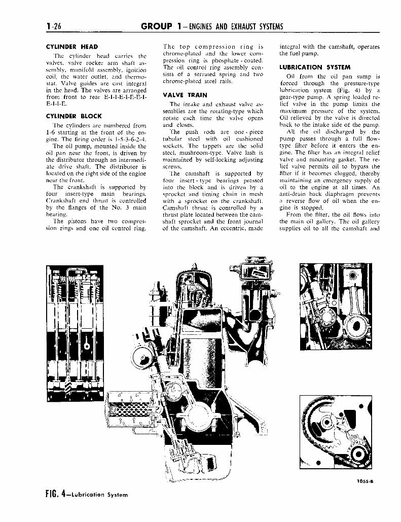
1-26 G R O U P 1-ENGINES AND EXHAUST SYSTEMS
CYLINDER HEAD
The cylinder head carries thevalves, valve rocker arm shaft as-sembly, manifold assembly, ignitioncoil, the water outlet, and thermo-stat. Valve guides are cast integralin the head. The valves are arrangedfrom front to rear E-I-I-E-I-E-E-I-E-I-I-E.
CYLINDER BLOCK
The cylinders are numbered from1-6 starting at the front of the en-gine. The firing order is 1-5-3-6-2-4.
The oil pump, mounted inside theoil pan near the front, is driven bythe distributor through an intermedi-ate drive shaft. The distributor islocated on the right side of the enginenear the front.
The crankshaft is supported byfour insert-type main bearings.Crankshaft end thrust is controlledby the flanges of the No. 3 mainbearing.
The pistons have two compres-sion rings and one oil control ring.
The top compression ring ischrome-plated and the lower com-pression ring is phosphate - coated.The oil control ring assembly con-sists of a serrated spring and twochrome-plated steel rails.
VALVE TRAIN
The intake and exhaust valve as-semblies are the rotating-type whichrotate each time the valve opensand closes.
The push rods are one - piecetubular steel with oil cushionedsockets. The tappets are the solidsteel, mushroom-type. Valve lash ismaintained by self-locking adjustingscrews.
The camshaft is supported byfour insert - type bearings pressedinto the block and is driven by asprocket and timing chain in meshwith a sprocket on the crankshaft.Camshaft thrust is controlled by athrust plate located between the cam-shaft sprocket and the front journalof the camshaft. An eccentric, made
integral with the camshaft, operatesthe fuel pump.
LUBRICATION SYSTEM
Oil from the oil pan sump isforced through the pressure-typelubrication system (Fig. 4) by agear-type pump. A spring loaded re-lief valve in the pump limits themaximum pressure of the system.Oil relieved by the valve is directedback to the intake side of the pump.
All the oil discharged by thepump passes through a full flow-type filter before it enters the en-gine. The filter has an integral reliefvalve and mounting gasket. The re-lief valve permits oil to bypass thefilter if it becomes clogged, therebymaintaining an emergency supply ofoil to the engine at all times. Ananti-drain back diaphragm preventsa reverse flow of oil when the en-gine is stopped.
From the filter, the oil flows intothe main oil gallery. The oil gallerysupplies oil to all the camshaft and
1055-B
FIG. 4—Lubrication System
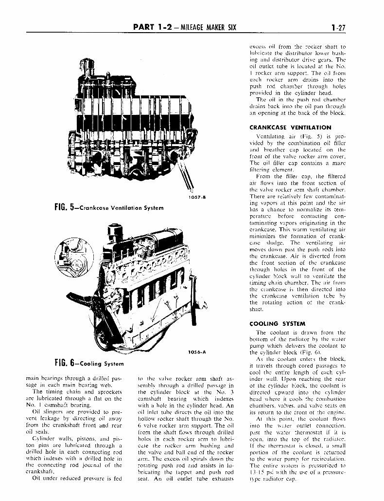
P A R T 1 - 2 - MILEAGE MAKER SIX 1-27
1057-B
FIG. 5—Crankcase Ventilation System
FIG. 6—Cooling System
main bearings through a drilled pas-sage in each main bearing web.
The timing chain and sprocketsare lubricated through a flat on theNo. 1 camshaft bearing.
Oil slingers are provided to pre-vent leakage by directing oil awayfrom the crankshaft front and rearoil seals.
Cylinder walls, pistons, and pis-ton pins are lubricated through adrilled hole in each connecting rodwhich indexes with a drilled hole inthe connecting rod journal of thecrankshaft.
Oil under reduced pressure is fed
1O56-A
to the valve rocker arm shaft as-sembly through a drilled passage inthe cylinder block at the No. 3camshaft bearing which indexeswith a hole in the cylinder head. Anoil inlet tube directs the oil into thehollow rocker shaft through the No.6 valve rocker arm support. The oilfrom the shaft flows through drilledholes in each rocker arm to lubri-cate the rocker arm bushing andthe valve and ball end of the rockerarm. The excess oil spirals down therotating push rod and assists in lu-bricating the tappet and push rodseat. An oil outlet tube exhausts
excess oil from the rocker shaft tolubricate the distributor lower bush-ing and distributor drive gears. Theoil outlet tube is located at the No.1 rocker arm support. The oil fromeach rocker arm drains into thepush rod chamber through holesprovided in the cylinder head.
The oil in the push rod chamberdrains back into the oil pan throughan opening at the back of the block.
CRANKCASE VENTILATION
Ventilating air (Fig. 5) is pro-vided by the combination oil fillerand breather cap located on thefront of the valve rocker arm cover.The oil filler cap contains a mazefiltering element.
From the filler cap, the filteredair flows into the front section ofthe valve rocker arm shaft chamber.There are relatively few contaminat-ing vapors at this point and the airhas a chance to normalize its tem-perature before contacting con-taminating vapors originating in thecrankcase. This warm ventilating airminimizes the formation of crank-case sludge. The ventilating airmoves down past the push rods intothe crankcase. Air is diverted fromthe front section of the crankcasethrough holes in the front of thecylinder block wall to ventilate thetiming chain chamber. The air fromthe crankcase is then directed intothe crankcase ventilation tube bythe rotating action of the crank-shaft.
COOLING SYSTEMThe coolant is drawn from the
bottom of the radiator by the waterpump which delivers the coolant tothe cylinder block (Fig. 6).
As the coolant enters the block,it travels through cored passages tocool the entire length of each cyl-inder wall. Upon reaching the rearof the cylinder block, the coolant isdirected upward into the cylinderhead where it cools the combustionchambers, valves, and valve seats onits return to the front of the engine.
At this point, the coolant flowsinto the water outlet connection,past the water thermostat if it isopen, into the top of the radiator.If the thermostat is closed, a smallportion of the coolant is returnedto the water pump for recirculation.The entire system is pressurized to13-15 psi with the use of a pressure-type radiator cap.
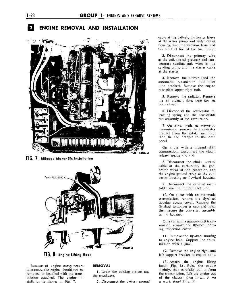
1-28 G R O U P 1-ENGINES AND EXHAUST SYSTEMS
ENGINE REMOVAL AND INSTALLATION
1806-A
FIG. 7—Mileage Maker Six Installation
Tool-T52L-6000-C
1060-A
FIG. 8—Engine Lifting Hook
Because of engine compartmenttolerances, the engine should not beremoved or installed with the trans-mission attached. The engine in-stallation is shown in Fig. 7.
REMOVAL
1. Drain the cooling system andthe crankcase.
2. Disconnect the battery ground
cable at the battery, the heater hosesat the water pump and water outlethousing, and the vacuum hose andflexible fuel line at the fuel pump.
3. Disconnect the primary wireat the coil, the oil pressure and tem-perature sending unit wires at thesending units, and the starter cableat the starter.
4. Remove the starter (and theautomatic transmission fluid fillertube bracket). Remove the enginerear plate upper right bolt.
5. Remove the radiator. Removethe air cleaner, then tape the airhorn closed.
6. Disconnect the accelerator re-tracting spring and the acceleratorrod assembly at the carburetor.
7. On a car with an automatictransmission, remove the acceleratorbracket from the intake manifold,then tie the bracket to the dashpanel.
On a car with a manual - shifttransmission, disconnect the clutchrelease spring and rod.
8. Disconnect the choke controlcable at the carburetor, the gen-erator wires at the generator, andthe engine ground strap at the con-verter housing or flywheel housing.
9. Disconnect the exhaust mani-fold from the muffler inlet pipe.
10. On a car with an automatictransmission, remove the flywheelhousing access cover. Remove theflywheel to converter nuts and bolts,then secure the converter assemblyin the housing.
On a car with a manual-shift trans-mission, remove the flywheel hous-ing inspection cover.
11. Remove the flywheel housingto engine bolts. Support the trans-mission with a jack.
12. Remove the engine right andleft support bracket to engine bolts.
13. Attach the engine liftinghook (Fig. 8) . Raise the engineslightly, then carefully pull it fromthe transmission. Lift the engine outof the chassis, then install it ona work stand (Fig. 9).
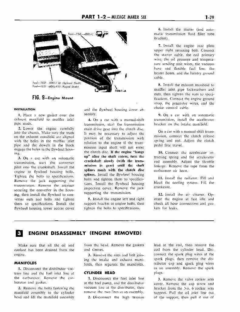
P A R T 1 - 2 - MILEAGE MAKER SIX 1-29
Too/—7527—6005-CJD (Splined Shaft)Tool—T52T—6005-KJD (Keyed Shaft)
FIG. 9—Engine Mount
INSTALLATION
1. Place a new gasket over theexhaust manifold to muffler inletpipe studs.
2. Lower the engine carefullyinto the chassis. Make sure the studson the exhaust manifold are alignedwith the holes in the muffler inletpipe and the dowels in the blockengage the holes in the flywheel hous-ing.
3. On a car with an automatictransmission, start the converterpilot into the crankshaft. Install theengine to flywheel housing bolts.Tighten the bolts to specifications.Remove the jack supporting thetransmission. Remove the retainersecuring the converter in the hous-ing, then install the flywheel to con-verter nuts and bolts and tightenthem to specifications. Install theflywheel housing lower access cover
and the flywheel housing cover as-sembly.
4. On a car with a manual-shifttransmission, start the transmissionmain drive gear into the clutch disc.It may be necessary to adjust theposition of the transmission withrelation to the engine if the trans-mission input shaft will not enterthe clutch disc. If the engine "hangsup" after the shaft enters, turn thecrankshaft slowly (with the trans-mission in gear) until the shaftsplines mesh with the clutch discsplines. Install the flywheel housingbolts and tighten them to specifica-tions. Install the flywheel housinginspection cover. Remove the jacksupporting the transmission.
5. Install the engine left and rightsupport bracket to engine bolts, thentighten the bolts to specifications.
6. Install the starter (and auto-matic transmission fluid filler tubebracket).
7. Install the engine rear plateupper right retaining bolt. Connectthe starter cable, the coil primarywire, the oil pressure and tempera-ture sending unit wires, the vacuumhose and flexible fuel line, theheater hoses, and the battery groundcable.
8. Install the exhaust manifold tomuffler inlet pipe lockwashers andnuts, then tighten the nuts to speci-fications. Connect the engine groundstrap, the generator wires, and thechoke control cable.
9. On a car with an automatictransmission, install the acceleratorbracket on the intake manifold.
On a car with a manual-shift trans-mission, connect the clutch releasespring and rod. Adjust the clutchpedal free travel.
10. Connect the accelerator re-tracting spring and the acceleratorrod assembly. Adjust the throttlelinkage. Remove the tape from thecarburetor air horn.
11. Install the radiator. Fill andbleed the cooling system. Fill thecrankcase.
12. Install the air cleaner. Op-erate the engine at fast idle andcheck all hose connections and gas-kets for leaks.
ENGINE DISASSEMBLY (ENGINE REMOVED)
Make sure that all the oil andcoolant has been drained from theengine.
MANIFOLDS
1. Disconnect the distributor vac-uum line and the fuel inlet line atthe carburetor. Remove the car-buretor and gasket.
2. Remove the bolts fastening themanifold assembly to the cylinderhead and lift the manifold assembly
from the head. Remove the gasketsand sleeves.
3. Remove the nuts and bolt join-ing the intake and exhaust mani-folds, then separate the manifolds.
CYLINDER HEAD
1. Disconnect the fuel inlet lineat the fuel pump, and the distributorvacuum line at the distributor, thenremove the two lines as an assembly.
2. Disconnect the high tension
lead at the coil, then remove thecoil from the cylinder head. Dis-connect the spark plug wires at thespark plugs, then remove the dis-tributor cap and spark plug wiresas an assembly. Remove the sparkplugs.
3. Remove the valve rocker armcover. Remove the cap screw andbracket from the No. 6 rocker armsupport. Pull the oil inlet line outof the support, then pull it out of
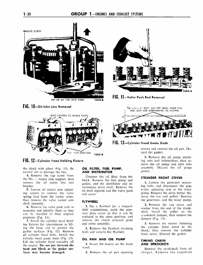
1-30 G R O U P 1-ENGINES AND EXHAUST SYSTEMS
REMOVE SCREW
1064-A
PRY UP OIL LINE WITH PLIERS 1063-AFIG. 11—Valve Push Rod Removal
FIG. 10—Oil Inlet Line Removal y 1 6 " _ 1 4 x 6 " BOLT. CUT OFF HEAD, TAPER ENDAND SLOT FOR SCREWDRIVER, AS SHOWN.
BOLT FIXTURES TO INTAKE PORTS
FIG. 13-Cylinder Head Guide Studs
Tool—T52P-6085-DAD1O65-B
FIG. 12—Cylinder Head Holding Fixture
the block with pliers (Fig. 10). Becareful not to damage the line.
4. Remove the cap screw fromthe No. 1 rocker arm support, thenremove the oil outlet line andbracket.
5. Loosen all rocker arm adjust-ing screws to remove the valvespring load from the rocker arms,then remove the valve rocker armshaft assembly.
6. Remove the valve push rods insequence and identify them so theycan be installed in their originalpositions (Fig. 11).
7. Install the cylinder head hold-ing fixtures for convenience in lift-ing the head and to protect thegasket surfaces (Fig. 12). Removeall cylinder head bolts. Install thecylinder head guide studs (Fig. 13).Lift the cylinder head assembly offthe engine. Do not pry between thehead and block as the gasket sur-faces may become damaged.
OIL FILTER, FUEL PUMP,AND DISTRIBUTOR
Unscrew the oil filter from theblock. Remove the fuel pump andgasket, and the distributor and in-termediate drive shaft. Remove theoil level dipstick and the valve pushrod cover.
FLYWHEEL
1. On a flywheel for a manual-shift transmission, mark the pres-sure plate cover so that it can bereplaced in the same position, andremove the clutch pressure plateand cover assembly.
2. Remove the flywheel retainingbolts and remove the flywheel.
OIL PAN AND OIL PUMP1. Invert the engine on the work
stand.
2. Remove the oil pan retaining
screws and remove the oil pan. Dis-card the gasket.
3. Remove the oil pump attach-ing nuts and lockwashers, then re-move the oil pump and inlet tubeassembly. Discard the oil pumpgasket.
CYLINDER FRONT COVER
1. Loosen the generator mount-ing bolts and disconnect the gen-erator adjusting arm at the waterpump. Remove the drive belt(s). Re-move the fan and pulley. Removethe generator, and the water pump.
2. Remove the cap screw andwasher from the end of the crank-shaft. Install the puller on thecrankshaft damper, then remove thedamper (Fig. 14).
3. Remove the screws fasteningthe cylinder front cover to theblock, then remove the cylinderfront cover. Discard the gasket.
TIMING CHAINAND SPROCKETS
Remove the crankshaft front oilslinger. Remove the camshaft