Embed Size (px)
Citation preview
Copyright © 2006, Forel Publishing Company, LLC, Woodbridge, Virginia
All Rights Reserved. No part of this book may be used or reproduced in any manner
whatsoever without written permission of Forel Publishing Company, LLC. For information write to Forel Publishing Company, LLC, 3999 Peregrine Ridge Ct.,
Woodbridge, VA 22192
1965 Comet, Falcon, Fairlane and Mustang Shop Manual (Form 7760-65, first printing September 1964)
ISBN 0-9673211-2-3 EAN: 978-0-9673211-2-7
Forel Publishing Company, LLC 3999 Peregrine Ridge Ct. Woodbridge, VA 22192
Email address: [email protected] Website: http://www.ForelPublishing.com
This publication contains material that is reproduced and distributed under a license from Ford Motor Company. No further reproduction or distribution of the Ford Motor Company material is allowed without the express written permission of Ford Motor Company.
Disclaimer
Although every effort was made to ensure the accuracy of this book, no representations or warranties of any kind are made concerning the accuracy, completeness or suitability of the information, either expressed or implied. As a result, the information contained within this book should be used as general information only. The author and Forel Publishing Company, LLC shall have neither liability nor responsibility to any person or entity with respect to any loss or damage caused, or alleged to be caused, directly or indirectly by the information contained in this book. Further, the publisher and author are not engaged in rendering legal or other professional services. If legal, mechanical, electrical, or other expert assistance is required, the services of a competent professional should be sought.
FOREWORD
This shop manual provides the Service Technician with com-
plete information for the proper servicing of the 1965 Comet,
Falcon, Fairlane and Mustang cars.
The information is grouped according to the type of work
being performed, such as diagnosis and testing, frequently
performed adjustments and repairs, in-vehicle adjustments,
overhaul, etc. Specifications and recommended special tools
are included.
Refer to the opposite page for important vehicle identifica-
tion data.
The descriptions and specifications in this manual were in
effect at the time this manual was approved for printing. The
Ford Motor Company reserves the right to discontinue models
at any time, or change specifications or design, without notice
and without incurring obligation.
SERVICE DEPARTMENT
FORD MOTOR COMPANY
12 VEHICLE IDENTIFICATION
BODY STYLE(FAIRLANE 5002-DOOR SEDAN)
EXTERIOR PAINT COLOR (WHITE) DATE CODE TRANSMISSION CODE
/
INTERIOR TRIM (26TH DAY OF AUGUST) (DUAL RANGE AUTOMATIC (C-4))
(TURQUOISE FABRIC AND / DETROIT AXLE RATIO CODELT. TURQUOISE MET. VINYL) / DISTRICT (3.00:1 AXLE RATIO)
\
.BODY CCOLOR TR IM
*62B XM 27 26H
5F4IC IOOOOI
THI1 VEMCLE% MANUFACTURED UNDER UNITED STATES
AWD FAVREIOOM PATENT^ AND PATENT APPLICATIONS
MODEL YEAR (1965) |
ASSEMBLY PLANT
(DEARBORN)
\ CONSECUTIVE UNIT NUMBER
ENGINE CODE (8 CYL. 289 CID ENGINE)I
BODY SERIAL CODE (2-DOOR SEDAN)R1184-C
FIG. 3—Fairlane Warranty Plate
EXTERIOR PAINT COLOR DATE CODE(WHITE) (6TH DAY APRIL)
BODY STYLE \ INTERIOR TRIM(2-DOOR HARDTOP) \ (PALOMINO VINYL) \ DETROIT DISTRICT
AXLE RATIO CODE(3.00:1 AXLE RATIO)
TRANSMISSION CODE(DUAL RANGE
AUTOMATIC (C-4))
89 06D
5FO7A 110196
THI5 M HldlE IS MANUFACTURED UNDER UNITED STATESA ND FOREIGN PAINTS AND PATENT APPLICATIONS
MODEL YEAR (1965) |ASSEMBLY PLANT
(DEARBORN)
\ CONSECUTIVE UNIT NUMBERENGINE CODE(8 CYL. 289 C10 ENGINE)
BODY SERIAL CODE (2-DOOR HARDTOP)
FIG. 4-Mustang Warranty Plate
N1406-A
FIG. 5-Vehicle IdentificationNumber Location—Comet, Falconand Mustang
IFIG. 6-Vehicle IdentificationNumber Location—Fairlane
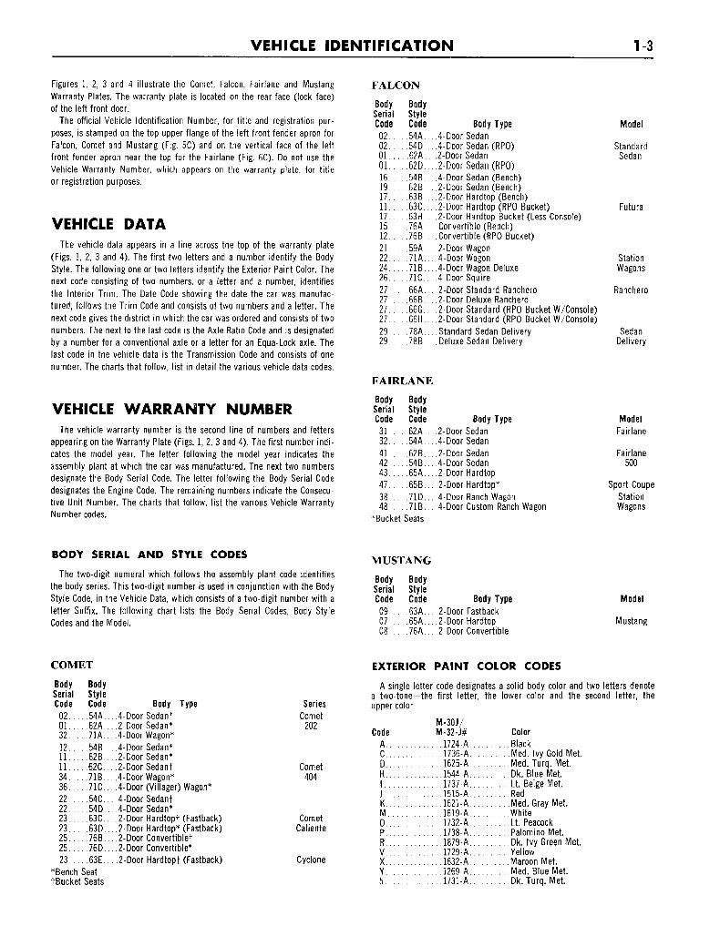
VEHICLE IDENTIFICATION 1-3
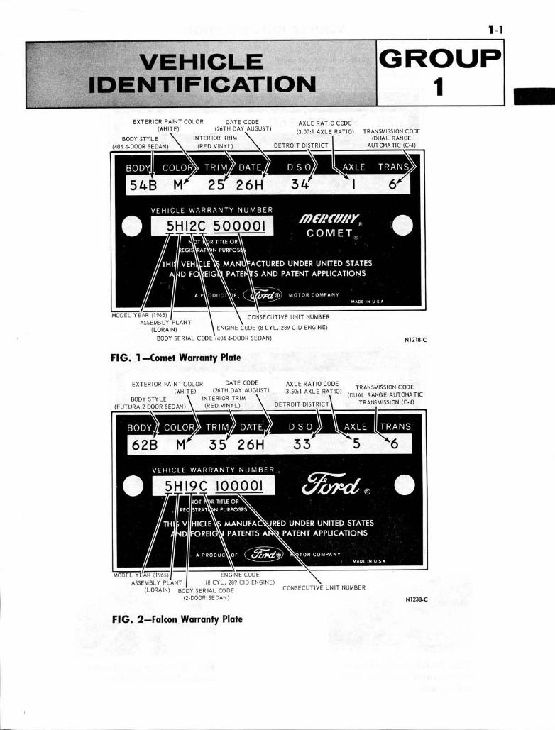
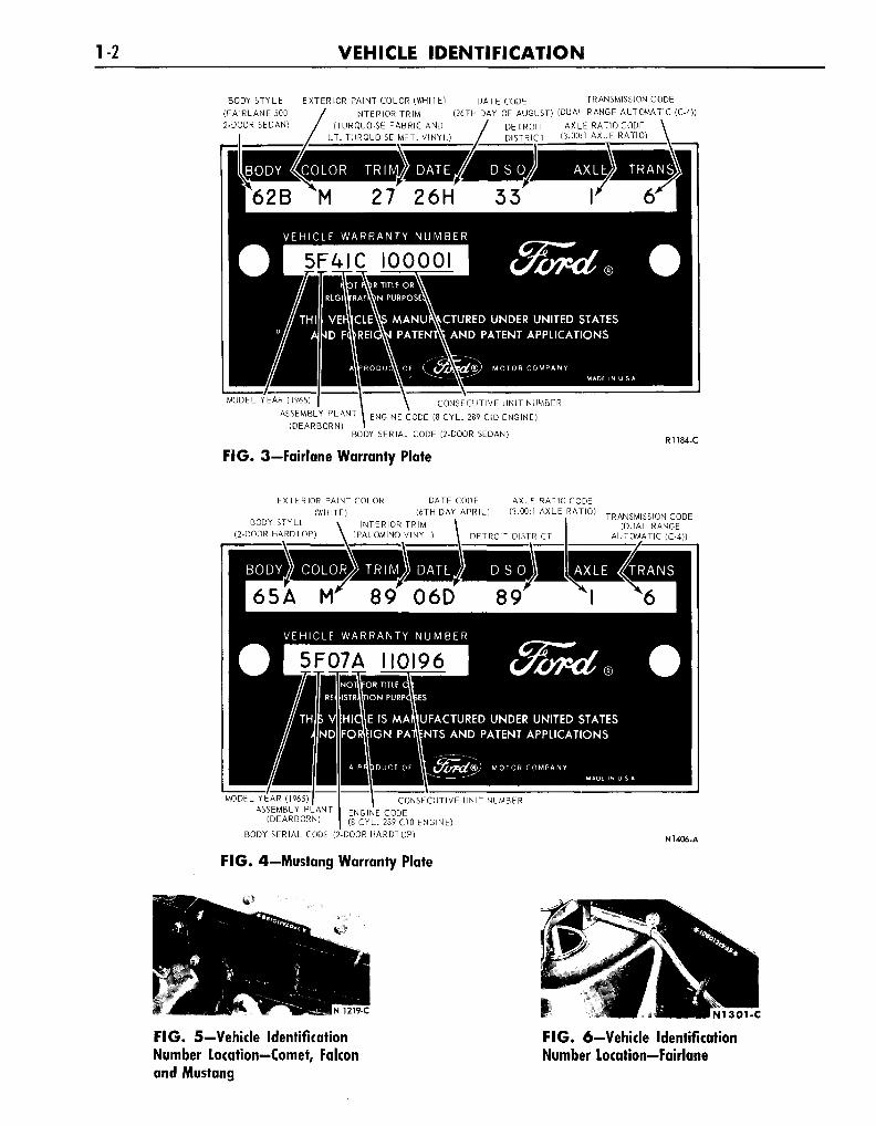
Figures 1, 2, 3 and 4 illustrate the Comet, Falcon, Fairlane and MustangWarranty Plates. The warranty plate is located on the rear face (lock face)of the left front door.
The official Vehicle Identification Number, for title and registration pur-poses, is stamped on the top upper flange of the left front fender apron forFalcon, Comet and Mustang (Fig. 5C) and on the vertical face of the leftfront fender apron near the top for the Fairlane (Fig. 6C). Do not use theVehicle Warranty Number, which appears on the warranty plate, for titleor registration purposes.
VEHICLE DATAThe vehicle data appears in a line across the top of the warranty plate
(Figs. 1, 2, 3 and 4). The first two letters and a number identify the BodyStyle. The following one or two letters identify the Exterior Paint Color. Thenext code consisting of two numbers, or a letter and a number, identifiesthe Interior Trim. The Date Code showing the date the car was manufac-tured, follows the Trim Code and consists of two numbers and a letter. Thenext code gives the district in which the car was ordered and consists of twonumbers. The next to the last code is the Axle Ratio Code and is designatedby a number for a conventional axle or a letter for an Equa-Lock axle. Thelast code in the vehicle data is the Transmission Code and consists of onenumber. The charts that follow, list in detail the various vehicle data codes.
VEHICLE WARRANTY NUMBERThe vehicle warranty number is the second line of numbers and letters
appearing on the Warranty Plate (Figs. 1, 2, 3 and 4). The first number indi-cates the model year. The letter following the model year indicates theassembly plant at which the car was manufactured. The next two numbersdesignate the Body Serial Code. The letter following the Body Serial Codedesignates the Engine Code. The remaining numbers indicate the Consecu-tive Unit Number. The charts that follow, list the various Vehicle WarrantyNumber codes.
BODY SERIAL AND STYLE CODES
The two-digit numeral which follows the assembly plant code identifiesthe body series. This two-digit number is used in conjunction with the BodyStyle Code, in the Vehicle Data, which consists of a two-digit number with aletter Suffix. The following chart lists the Body Serial Codes, Body StyleCodes and the Model.
FALCON
BodySerialCode0 2 . . .0 2 . . .0 1 . . .0 1 . . .16 . . .1 9 . . .17 . . .1 1 . . .17 . . .15 . . .12 . . .2 1 . . .2 2 . . .2 4 . . .2 6 . . .2 7 . . .2 7 . . .2 7 . . .2 7 . . .2 9 . . .2 9 . . .
BodyStyleCode
. .54A. . .
. .54D. . .
. .62A. .
. .62D. . .
. .54B. . .
. .62B. . .
. .63B. . .
. .63C. . .
. .63H.. .
. 76A...
. .76B. . .
. .59A. . .
. .71A. . .
. . 71B . . .
. .71C. . .,66A...
. .66B. . .
. .66G. . .
. .66H.. .
. .78A. . ., . 78B . . .
FAIRLANE
BodySerialCode
3 1 . . .3 2 . . .4 1 . . .4 2 . . .4 3 . . .4 7 . . .3 8 . . .4 8 . . .
*Bucket
BodyStyleCode
. 62A...
. .54A. . ., . 62B . . .. . 54B . . .. .65A. . .. . 65B . . .
,71D.... . 71B . . .Seats
MUSTANG
BodySerialCode
0 9 . . .07 . .0 8 . . .
BodyStyleCode
. 63A...
. 65A ..
. .76A. . .
Body Type.4-Door Sedan4-Door Sedan (RPO)
.2-Door Sedan2-Door Sedan (RPO)4-Door Sedan (Bench)2-Door Sedan (Bench)2-Door Hardtop (Bench)
.2-Door Hardtop (RPO Bucket)
.2-Door Hardtop Bucket (Less Console)Convertible (Bench)Convertible (RPO Bucket)2-Door Wagon
.4-Door Wagon4-Door Wagon Deluxe4-Door Squire
.2-Door Standard Ranchero
.2-Door Deluxe Ranchero2-Door Standard (RPO Bucket W/Console)
.2-Door Standard (RPO Bucket W/Console)Standard Sedan DeliveryDeluxe Sedan Delivery
Body Type.2-Door Sedan4-Door Sedan2-Door Sedan
.4-Door Sedan2-Door Hardtop2-Door Hardtop*4-Door Ranch Wagon
.4-Door Custom Ranch Wagon
Body Type2-Door Fastback2-Door Hardtop2-Door Convertible
Model
StandardSedan
Futura
StationWagons
Ranchero
SedanDelivery
ModelFairlane
Fairlane500
Sport CoupeStationWagons
Model
Mustang
COMET
BodySerialCode
0 2 . . .0 1 . . .3 2 . . .1 2 . . .1 1 . . .1 1 . . .3 4 . . .3 6 . . .2 2 . . .2 2 . . .2 3 . . .2 3 . . .2 5 . . .2 5 . . .2 3 . . .
*BenchtBucket
BodyStyleCode
. .54A. . .
. .62A. . .
. .71A. . .
. . 54B . . .
. . 62B . . .
. .62C. . .
. . 71B . . .
. .71C. . .
. .54C. . .
. .54D. . .
. .63C. . .
. .63D. . .
. . 76B . . .
. .76D. . .
. . 63E . . .SeatSeats
Body Type.4-Door Sedan*2-Door Sedan*4-Door Wagon*4-Door Sedan*
.2-DoorSedan*2-DoorSedanf
.4-DoorWagon*4-Door (Villager) Wagon*
.4-Door Sedanf4-Door Sedan*2-Door Hardtopf (Fastback)2-Door Hardtop* (Fastback)2-Door Convertible!
.2-Door Convertible*
.2-Door Hardtopf (Fastback)
SeriesComet
202
Comet404
CometCaliente
Cyclone
EXTERIOR PAINT COLOR CODES
A single letter code designates a solid body color and two letters denotea two-tone—the first letter, the lower color and the second letter, theupper color
CodeA..C .D..H..I . .J . .K..M.O..P..R..V. .X. .Y. .5 . .
M-30J/M-32-J#. .1724-A...1736-A...1625-A...1544-A...1737-A...1515-A.. .1621-A.. .1619-A.. .1732-A.. 1738-A...1879-A.. 1729-A...1632-A.. 1269-A...1731-A.
ColorBlackMed. Ivy Gold MetMed. Turq. Met.Dk. Blue Met.Lt. Beige Met.RedMed. Gray Met.WhiteLt. PeacockPalomino Met.Dk. Ivy Green MetYellowMaroon Met.Med. Blue Met.Dk. Turq. Met.
14 VEHICLE IDENTIFICATION
INTERIOR TRIM CODES
Code Trim Codes04 Beige Vinyl12 Med. Blue and Lt. Blue Met. Fabric and Vinyl15 Red Fabric and Vinyl16 Black Fabric and Vinyl17 Med. Turq. and Lt. Turq. Met. Fabric and Vinyl19 . . Palomino and Med. Palomino Fabric and Vinyl22 Med. and Lt. Blue Met. Vinyl (Comet),
Fabric and Vinyl (Except Comet)25 . . . . Red Vinyl (Comet), Fabric and Vinyl (Except Comet)26 Black Vinyl27 Med. and Lt. Turquoise Met. Vinyl (Comet),
Fabric and Vinyl (Except Comet)28 Ivy Gold and Lt. Ivy Gold D/L Fabric and Vinyl29 Palomino Vinyl (Comet), Fabric and Vinyl (Except Comet)32 Med. Blue and Lt. Blue Met. Fabric and Vinyl (Comet)
Vinyl (Except Comet)35 Red Fabric and Vinyl (Comet) Vinyl (Except Comet)36 Black Fabric and Vinyl (Comet) Vinyl (Except Comet)37 Med. Turquoise and Lt. Turq. Met. Fabric and Vinyl (Comet)
Vinyl (Except Comet)38 Ivy Gold Fabric and Vinyl (Comet) Vinyl (Except Comet)39 Palomino and Med. Palomino Fabric and Vinyl (Comet)
Vinyl (Except Comet)42 White and Blue Vinyl45 White and Red Vinyl46 White and Black Vinyl48 White and Ivy Gold Vinyl49 Med. Palomino Vinyl52 Med. Blue and Lt. Blue Met. Fabric and Vinyl (Comet),
Vinyl (Except Comet)55 Red Fabric and Vinyl (Comet), Vinyl (Except Comet)56 Black Fabric and Vinyl (Comet), Vinyl (Except Comet)59 Palomino and Med. Palomino Fabric and Vinyl (Comet),
Vinyl (Except Comet)F2 White Pearl (W/Red) Fabric and VinylF5 White Pearl (W/Black) Fabric and VinylF6 White Pearl (W/Turquoise) Fabric and VinylF8 White Pearl (W/Gold) Fabric and VinylF9 White Pearl (W/Palomino) Fabric and Vinyl62 Lt. Blue Met. Vinyl65 Red Vinyl66 Black Vinyl67 Turquoise Vinyl68 Ivy Gold Met. and D/L Vinyl69 Med. Palomino VinylG2 White Pearl (W/Blue) VinylG5 White Pearl (W/Red) VinylG6 White Pearl (W/Black) VinylG7 White Pearl (W/Turquoise) VinylG8 White Pearl (W/Gold) VinylG9 White Pearl (W/Palomino) Vinyl72 Lt. Blue Met. Vinyl75 Red Vinyl76 Black Vinyl77 Lt. Turq. Met. Vinyl78 Ivy Gold D/L Vinyl79 . . Med. Palomino VinylH2 White (W/Blue) VinylH5 White (W/Red) VinylH6 White (W/Black) VinylH7 White (W/Turquoise) VinylH8 White (W/Gold) VinylH9 White (W/Palomino) Vinyl82 Lt. and Med. Blue Met. Vinyl85 Red Vinyl86 Black Vinyl87 Lt. Turq. Met. Vinyl88 Lt. Ivy Gold Met. Vinyl89 Med. Palomino Vinyl92 Blue Vinyl95 Red Vinyl96 Black Vinyl (Except Fairlane) Fabric and Vinyl (Fairlane)99 Palomino Vinyl (Except Fairlane) Fabric and Vinyl (Fairlane)
DATE CODES
A number signifying the date precedes the month code letter. A second-yearcode letter will be used if the model exceeds exceeds 12 months.
MonthJanuary...February..MarchAprilMayJuneJulyAugus t . . .September.October...November.December.
CodeFirst Year
CodeSecond Year
. . . . NPQRSTUVwXYZ
DISTRICT CODES (DSO)
Units built on a Domestic Special Order, Foreign Special Order, or otherspecial orders will have the complete order number in this space. Also toappear in this space is the two-digit code number of the District whichordered the unit. If the unit is a regular production unit, only the Districtcode number will appear.
COMET
Code1116151421222326313233
DistrictBoston
PhiladelphiaNew York
WashingtonAtlanta
DallasJacksonville
MemphisBuffalo
CincinnatiCleveland
Code3441424551525354818490-99...
DistrictDetroit
ChicagoSt. Louis
Twin CitiesDenver
Los AngelesOakland
SeattleFord of Canada
.. Home Office ReserveExport
FALCON, FAIRLANE AND MUSTANG
Code District Code District111213141521222324252631323334353641424344
BostonBuffalo
New YorkPittsburgh
NewarkAtlanta
CharlottePhiladelphiaJacksonville
RichmondWashington
CincinnatiCleveland
DetroitIndianapolis
LansingLouisville
ChicagoFargo
RockfordTwin Cities
45515253545561626364657 1 . . . .727 3 . . . .74.. ..818 3 . . . .848 5 . . . .8990-99..
DavenportDenver
Des MoinesKansas City
OmahaSt. Louis
DallasHouston
MemphisNew Orleans
Oklahoma CityLos Angeles
San JoseSalt Lake City
SeattleFord of Canada
Government.Home Office Reserve
American Red CrossTransportation Services
Export
VEHICLE IDENTIFICATION 15
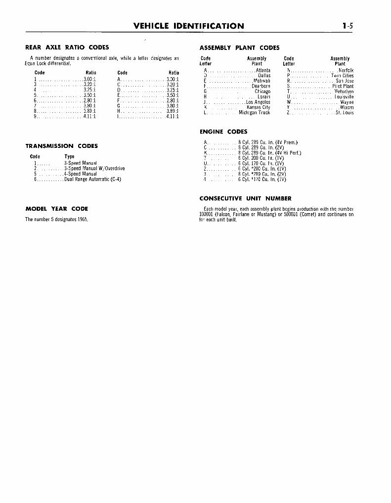
REAR AXLE RATIO CODES
A number designates a conventional axle, while a letter designates anEqua-Lock differential.
Code
1 . . . .34 . . . .56789
Ratio.3.00:1.3.20:1.3.25:1.3.50:1.2.80:1.3.80:1.3.89:1.4.11:1
CodeA . . .C. . .D. . .E....F . . . .G . . . .H . . .I
Ratio.3.00:13.20:1
.3.25:1
.3.50:1
.2.80:1
.3.80:1
.3.89:1
.4.11:1
ASSEMBLY
CodeLetter
ADEFGHJKL
PLANT CODES
AssemblyPlant
AtlantaDallas
MahwahDearborn
ChicagoLorain
Los AngelesKansas City
. .Michigan Truck
CodeLetter
NPRS . . . .T
uWYZ
AssemblyPlant
NorfolkTwin Cities
San JosePilot PlantMetuchenLouisville
WayneWixom
St. Louis
TRANSMISSION CODES
Code1256
Type3-Speed Manual3-Speed Manual W/Overdrive4-Speed ManualDual Range Automatic (C-4)
ENGINE CODES
A 8 Cyl. 289 Cu. In. (4V Prem.)C 8 Cyl. 289 Cu. In. (2V)K 8 Cyl. 289 Cu. In. (4V Hi-Perf.)T 6 Cyl. 200 Cu. In. (IV)U 6 Cyl. 170 Cu. In. (IV)2 6 Cyl. *200 Cu. In. (IV)3 8 Cyl. *289 Cu. In. (2V)4 6 Cyl. *170 Cu. In. ( IV)
MODEL YEAR CODE
The number 5 designates 1965.
CONSECUTIVE UNIT NUMBER
Each model year, each assembly plant begins production with the number100001 (Falcon, Fairlane or Mustang) or 500001 (Comet) and continues onfor each unit built.
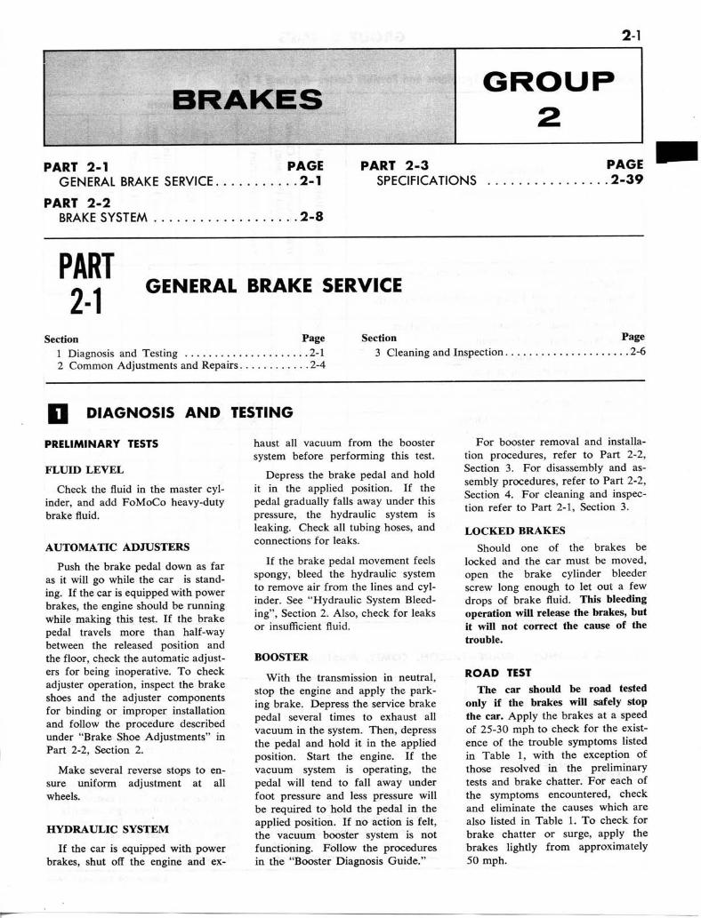
2-2 GROUP 2-BRAKES
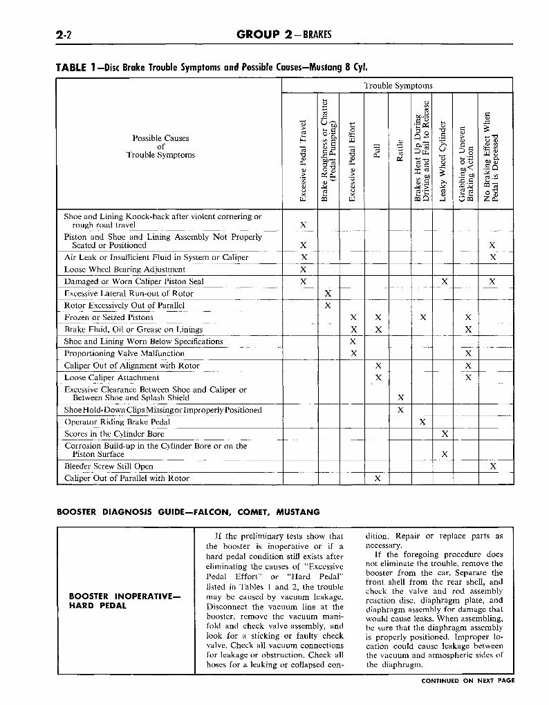
TABLE 1 —Disc Brake Trouble Symptoms and Possible Causes—Mustang 8 Cyl.
Possible Causesof
Trouble Symptoms
Shoe and Lining Knock-back after violent cornering orrough road travel
Piston and Shoe and Lining Assembly Not ProperlySeated or Positioned
Air Leak or Insufficient Fluid in System or CaliperLoose Wheel Bearing AdjustmentDamaged or Worn Caliper Piston SealExcessive Lateral Run-out of RotorRotor Excessively Out of ParallelFrozen or Seized PistonsBrake Fluid, Oil or Grease on LiningsShoe and Lining Worn Below SpecificationsProportioning Valve MalfunctionCaliper Out of Alignment with RotorLoose Caliper AttachmentExcessive Clearance Between Shoe and Caliper or
Between Shoe and Splash ShieldShoe Hold-Down Clips Missing or Improperly PositionedOperator Riding Brake PedalScores in the Cylinder BoreCorrosion Build-up in the Cylinder Bore or on the
Piston SurfaceBleeder Screw Still OpenCaliper Out of Parallel with Rotor
Trouble Symptoms
Exc
essi
ve P
edal
Tra
vel
X
X
X
X
X
Bra
ke R
ough
ness
or
Cha
tter
(Ped
al P
umpi
ng)
X
X
Exc
essi
ve P
edal
Eff
ort
X
X
X
X
Pull
X
X
X
X
X
Rat
tle
X
XB
rake
s H
eat
Up
Dur
ing
Dri
ving
and
Fai
l to
Rel
ease
X
X
Lea
ky W
heel
Cyl
inde
r
X
X
XG
rabb
ing
or U
neve
nB
raki
ng A
ctio
n
X
X
X
X
X
No
Bra
king
Eff
ect
Whe
nPe
dal
is D
epre
ssed
X
X
X
X
BOOSTER DIAGNOSIS GUIDE—FALCON, COMET, MUSTANG
BOOSTER INOPERATIVE-HARD PEDAL
If the preliminary tests show thatthe booster is inoperative or if ahard pedal condition still exists aftereliminating the causes of "ExcessivePedal Effort" or "Hard Pedal"listed in Tables 1 and 2, the troublemay be caused by vacuum leakage.Disconnect the vacuum line at thebooster, remove the vacuum mani-fold and check valve assembly, andlook for a sticking or faulty checkvalve. Check all vacuum connectionsfor leakage or obstruction. Check allhoses for a leaking or collapsed con-
dition. Repair or replace parts asnecessary.
If the foregoing procedure doesnot eliminate the trouble, remove thebooster from the car. Separate thefront shell from the rear shell, andcheck the valve and rod assemblyreaction disc, diaphragm plate, anddiaphragm assembly for damage thatwould cause leaks. When assembling,be sure that the diaphragm assemblyis properly positioned. Improper lo-cation could cause leakage betweenthe vacuum and atmospheric sides ofthe diaphragm.
CONTINUED ON NEXT PAGE
P A R T 2-1-GENERAL BRAKE SERVICE 23
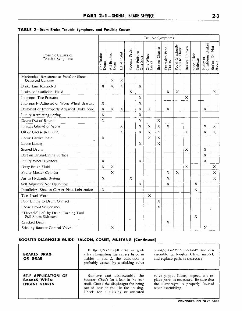
TABLE 2—Drum Brake Trouble Symptoms and Possible
Possible Causes ofTrouble Symptoms
Mechanical Resistance at Pedal or ShoesDamaged Linkage
Brake Line Restricted
Leaks or Insufficient Fluid
Improper Tire Pressure
Improperly Adjusted or Worn Wheel Bearing
Distorted or Improperly Adjusted Brake Shoe
Faulty Retracting Spring
Drum Out of Round
Linings Glazed or Worn
Oil or Grease In Lining
Loose Carrier Plate
Loose Lining
Scored Drum
Dirt on Drum-Lining Surface
Faulty Wheel Cylinder
Dirty Brake Fluid
Faulty Master Cylinder
Air in Hydraulic System
Self Adjusters Not Operating
Insufficient Shoe-to-Carrier Plate Lubrication
Tire Tread Worn
Poor Lining to Drum Contact
Loose Front Suspension
"Threads" Left by Drum Turning ToolPull Shoes Sideways
Cracked DrumSticking Booster Control Valve
Causes
Trouble Symptoms
One
Bra
keD
rags
X
X
X
X
X
X
X
X
X
X
All
Bra
kes
Dra
g
X
X
X
X
X
X
Har
d Pe
dal
X
X
X
X
XSp
ongy
Ped
al
X
X
Car
Pul
ls t
oOn
e Si
de
X
X
X
X
X
X
X
X
X
X
X
One
Whe
elL
ocks
X
X
X
X
X
X
Bra
kes
Cha
tter
X
X
X
X
X
X
X
Exc
essi
ve P
edal
Tra
vel
X
X
X
X
X
X
X
Peda
l G
radu
ally
Goe
s to
Flo
or
X
X
Bra
kes
Une
ven
X
X
X
X
Shoe
Clic
kR
elea
se
X
X
X
Noi
sy o
rG
rabb
ing
Bra
kes
X
X
X
X
X
X
X
Bra
kes
Do
Not
App
ly
X
X
X
X
X
X
BOOSTER DIAGNOSIS GUIDE—FALCON, COMET, MUSTANG (Continued)
BRAKES DRAGOR GRAB
SELF APPLICATION OFBRAKES WHENENGINE STARTS
If the brakes still drag or grab plunger assembly. Remove and dis-after eliminating the causes listed in assemble the booster. Clean, inspect,Tables 1 and 2, the condition is and replace parts as necessary,probably caused by a sticking valve
Remove and disassemble the valve poppet. Clean, inspect, and re-booster. Check for a leak in the rear place parts as necessary. Be sure thatshell. Check the diaphragm for being the diaphragm is properly locatedout of locating radii in the housing. when assembling.Check for a sticking or unseated
CONTINUED ON NEXT PAGE
2-4 G R O U P 2-BRAKES
BRAKE BOOSTER TROUBLE DIAGNOSIS GUIDE—FAIRLANE
BOOSTER INOPERATIVE-HARD PEDAL
BRAKES DRAG OR GRAB
SELF APPLICATIONOF BRAKES WHENENGINE STARTS
If the preliminary tests show that leaking or collapsed condition. Re-the booster is inoperative or if a pair or replace parts as necessary,hard pedal condition still exists after If the foregoing procedure doeseliminating the causes of "Hard not eliminate the trouble, removePedal" listed in Table 2, the trouble the booster from the car. Separatemay be caused by vacuum leakage. the booster body from the end plate,Disconnect the vacuum line (two and check the bellows, booster body,lines if equipped with an automatic and diaphragm assembly for damagetransmission) at the booster, remove that would cause leaks. When assem-the vacuum manifold and check bling, be sure that the diaphragmvalve assembly, and look for a stick- assembly is properly positioned. Im-ing or faulty check valve. Check all proper location could cause leakagevacuum connections for leakage or between the vacuum and atmos-obstruction. Check all hoses for a pheric sides of the diaphragm.
If the brakes still drag or grab assembly. Remove and disassembleafter eliminating the causes listed in the booster. Clean, inspect, and re-Table 1, the condition is probably place parts as necessary,caused by a sticking valve plunger
Remove and disassemble the seated atmospheric valve. Clean, in-booster. Check the diaphragm for spect, and replace parts as necessary,being out of locating radii in the Be sure that the diaphragm is prop-housing. Check for a sticking or un- erly located when assembling.
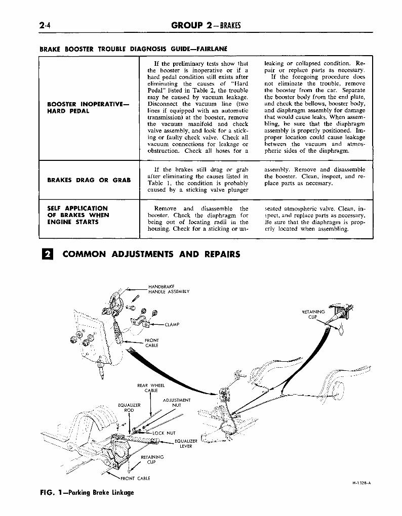
COMMON ADJUSTMENTS AND REPAIRS
HANDBRAKEHANDLE ASSEMBLY
•FRONT CABLE
F IG . 1 — Parking Brake Linkage
H-1328-A
P A R T 2-1 -GENERAL BRAKE SERVICE 25
PARKING BRAKELINKAGE ADJUSTMENT
Check the parking brake cableswhen the brakes are fully released.If the cables are loose, adjust themas follows:
1. Fully release the parking brakeby turning the handle counterclock-wise and pushing it inward.
2. Pull the parking brake handleoutward to the third notch from itsnormal released position.
3. Raise the car.4. On a Falcon, Comet or Fair-
lane, turn the lock nut in front ofthe equalizer (Fig. 1) several turnsforward.
5. On all cars, turn the adjustmentnut forward against the equalizeruntil a moderate drag is felt whenturning the rear wheels in the direc-tion of forward rotation.
6. When the cables are properlyadjusted on a Falcon, Comet or Fair-lane, tighten the lock nut againstthe equalizer.
7. Release the parking brake, andmake sure that the brake shoes re-turn to the fully released positionand no drag is felt when turningthe rear wheels.
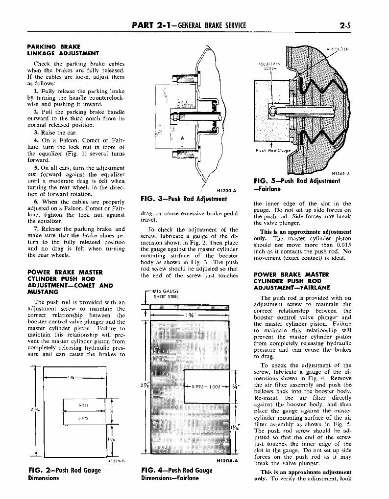
POWER BRAKE MASTERCYLINDER PUSH RODADJUSTMENT—COMET ANDMUSTANG
The push rod is provided with anadjustment screw to maintain thecorrect relationship between thebooster control valve plunger and themaster cylinder piston. Failure tomaintain this relationship will pre-vent the master cylinder piston fromcompletely releasing hydraulic pres-sure and can cause the brakes to
AIR FILTER
( H1330-A
F IG . 3—Push Rod Adjustment
drag, or cause excessive brake pedaltravel.
To check the adjustment of thescrew, fabricate a gauge of the di-mension shown in Fig. 2. Then placethe gauge against the master cylindermounting surface of the boosterbody as shown in Fig. 3. The pushrod screw should be adjusted so thatthe end of the screw just touches
HI 32 9-1 H12O8-A
F IG . 2—Push Rod GaugeDimensions
F IG . 4—Push Rod GaugeDimensions—Fairlane
H1349-A
FIG. 5-Push Rod Adjustment—Fairlane
the inner edge of the slot in thegauge. Do not set up side forces onthe push rod. Side forces may breakthe valve plunger.
This is an approximate adjustmentonly. The master cylinder pistonshould not move more than 0.015inch as it contacts the push rod. Nomovement (exact contact) is ideal.
POWER BRAKE MASTERCYLINDER PUSH RODADJUSTMENT—FAIRLANE
The push rod is provided with anadjustment screw to maintain thecorrect relationship between thebooster control valve plunger andthe master cylinder piston. Failureto maintain this relationship willprevent the master cylinder pistonfrom completely releasing hydraulicpressure and can cause the brakesto drag.
To check the adjustment of thescrew, fabricate a gauge of the di-mensions shown in Fig. 4. Removethe air filter assembly and push thebellows back into the booster body.Re-install the air filter directlyagainst the booster body, and thenplace the gauge against the mastercylinder mounting surface of the airfilter assembly as shown in Fig. 5.The push rod screw should be ad-justed so that the end of the screwjust touches the inner edge of theslot in the gauge. Do not set up sideforces on the push rod as it maybreak the valve plunger.
This is an approximate adjustmentonly. To verify the adjustment, look
2-6 G R O U P 2-BRAKES
through the make-up (rear) portwhen installing the master cylinderto the booster. The master cylinderpiston should not move more than0.015 inch as it contacts the pushrod. No movement (exact contact)is ideal.
HYDRAULIC SYSTEM BLEEDING
When any part of the hydraulicsystem has been disconnected for re-pair or replacement, air may getinto the lines and cause spongy pedalaction. Bleed the hydraulic systemafter it has been properly connectedto be sure that all air is expelledfrom the brake cylinders or discbrake calipers, and lines.
The hydraulic system can be bledmanually or with pressure bleedingequipment.
With disc brakes, more pumpingof the pedal is required and morefrequent checking of the master cyl-inder may be necessary while bleed-ing.
On a Mustang with disc brakes,remove the front wheel and tire as-semblies in order to gain access tothe bleeder fitting on the disc brakecalipers.
MANUAL BLEEDINGBleed the longest lines first. Keep
the master cylinder reservoir filledwith new SAE 70R3-Wagner 2IB(301) brake fluid during the bleedingoperation.
Never use brake fluid which hasbeen drained from the hydraulic sys-tem.
1. Position a bent %-inch boxwrench on the bleeder fitting on the
APPROXIMATELY 45C
HI 300-A
FIG. 6-Brake Bleeder Wrench
right rear brake wheel cylinder (Fig.6). Attach a rubber drain tube tothe bleeder fitting. The end of thetube should fit snugly around thebleeder fitting.
2. Submerge the free end of thetube in a container partially filledwith clean brake fluid, and loosenthe bleeder fitting approximately %turn.
3. Push the brake pedal downslowly through its full travel. Closethe bleeder fitting, then return thepedal to the fully-released position.Repeat this operation until air bub-bles cease to appear at the sub-merged end of the tube.
4. When the fluid is completelyfree of air bubbles, close the bleederfitting and remove the drain tube.
5. Repeat this procedure on thebrake cylinders or disc calipers ateach wheel in order: left rear, rightfront, and left front. Refill the mas-ter cylinder reservoir after eachbrake cylinder is bled and when thebleeding operation is completed. Thefluid level should be within 3/s inchof the top of the reservoir. The dia-phragm-type gasket should be prop-erly positioned in the reservoir capbefore the cap is installed.
6. On a Mustang with disc brakes,be sure that the front brake pistonsare returned to their normal posi-tions and that the shoe and liningassemblies are properly seated.
7. Before driving the car, checkthe operation of the brakes and besure that a firm pedal is obtained.
PRESSURE BLEEDINGBleed the longest lines first. Never
use brake fluid which has beendrained from the hydraulic system.
The bleeder tank should containenough new heavy-duty brake fluidto complete the bleeding operation,and it should be charged with 10-30pounds of air pressure.
1. Clean all dirt from the mastercylinder reservoir cap.
2. Remove the master cylinderreservoir cap, install an adapter
cap to the reservoir, and attach thebleeder tank hose to the fitting onthe adapter cap.
An adapter cap can be fabricatedby cutting a hole in the center of areservoir cap and soldering a fittingat the hole. The adapter cap m^stbe securely seated and completelysealed on the master cylinder orleakage will occur.
3. Position a 3/s-inch box wrenchon the bleeder fitting on the rightrear brake wheel cylinder (Fig. 6).Attach a rubber drain tube to thebleeder fitting. The end of the tubeshould fit snugly around the bleederfitting.
4. Open the valve on the bleedertank to admit pressurized brake fluidto the master cylinder reservoir.
5. Submerge the free end of thetube in a container partially filledwith clean brake fluid, and loosenthe bleeder fitting.
6. When air bubbles cease to ap-pear in the fluid at the submergedend of the drain tube, close thebleeder fitting and remove the tube.
7. Repeat this procedure on thebrake cylinder or disc caliper at eachwheel in order: left rear, right front,and left front. Refill the master cyl-inder reservoir after each brake cyl-inder is bled.
8. When the bleeding operation iscompleted, close the bleeder tankvalve and remove the tank hose fromthe adapter fitting.
9. Remove the adapter cap, refillthe master cylinder reservoir to with-in 3/8-inch from the top of the res-ervoir. Be sure that the diaphragm-type gasket is properly positioned inthe reservoir cap, and then installthe cap.
10. On a Mustang with discbrakes, be sure that the front brakepistons are returned to their normalpositions and that the shoe and lin-ing assemblies are properly seated.
11. Before driving the car, checkthe operation of the brakes and besure that a firm pedal is obtained.
CLEANING AND INSPECTION
DISC BRAKES
1. Remove the wheel and tire as-sembly, caliper splash shield, and theshoe and lining assemblies as out-lined in Part 2-2, Section 2.
2. Make three thickness measure-ments with a micrometer across themiddle section of the shoe and lin-ing. Take one reading at each sideand one in the center. If the assem-bly has worn to a thickness of 0.195-
inch (shoe and lining together) or0.030 -inch (lining material only) atany one of the three measuring loca-tions, replace all (4) shoe and liningassemblies on both front wheels.
3. With the shoe and lining assem-
P A R T 2-1 -GENERAL BRAKE SERVICE 2-7
blies installed, insert a feeler gaugebetween the lining and rotor. If theclearance is not within 0.002-0.010-inch, check for shoe and lining as-semblies not being properly seatedon the caliper bridges, for a pistonpushed back in the cylinder bore, fora seized piston, or for malfunctionof a piston seal.
Ordinarily, the clearance shouldbe 0.002-0.010-inch. However, ifthe vehicle was stopped by a brakeapplication just prior to checkingthe clearance, the brakes may dragslightly.
4. To check rotor runout, firsteliminate the wheel bearing end playby tightening the adjusting nut. Aftertightening the nut check to see thatthe rotor can still be rotated.
5. Clamp a dial indicator to thecaliper housing so that the styluscontacts the rotor at a point approxi-mately 1-inch from the outer edge.Rotate the rotor and take an indica-tor reading. If the reading exceeds0.002-inch total indicator runout, re-place the rotor. Do not attempt torefinish a rotor that indicates runoutin excess of specification. When therunout check is finished be sure toadjust the bearings as outlined inGroup 3, in order to prevent bear-ing failure.
6. Check the rotor for scoring.Minor scores can be removed witha fine emery cloth. If the rotor isexcessively scored, replace it.
7. Visually check the caliper. If itis cracked or if excess leakage is evi-dent, it should be replaced. Slightleakage or seized pistons indicate re-moval and disassembly.
8. If upon disassembly the caliperis found to be distorted or damaged,or if the cylinder bores are scoredor excessively worn, replace the as-sembly.
The two halves of the caliper as-sembly should never be separated.Damage or failure of one requiresreplacement of both as a unit.
DRUM BRAKES
1. Remove the wheel from thedrum, and remove the drum as out-lined in Part 2-2, Section 2. Washall the parts except the brake shoesin a cleaning fluid and dry with com-pressed air.
2. Brush all dust from the carrierplate and interior of the brake drum.
3. Inspect the brake shoes for ex-cessive lining wear or shoe damage.If the lining is worn to within 1/32-inch of the rivet heads or if theshoes are damaged, they must be re-placed. Replace any lining that hasbeen oil saturated. Replace the lin-ing in axle sets. Prior to replacementof the lining, the drum diametershould be checked to determine ifoversize linings must be installed.
4. Check the condition of thebrake shoes, retracting springs, anddrum for signs of overheating. If theshoes have a slight blue coloring, orif the springs show a change in freelength, indicating overheating, re-placement of the retracting and holddown springs is necessary. Over-heated springs lose their pull andcould cause the new lining to wearprematurely if they are not replaced.
5. If the car has 30,000 or moremiles of operation on the brake lin-ings, or signs of overheating arepresent when relining brakes, thewheel cylinders should be disassem-bled and inspected for wear and dirtin the cylinder. The cylinder cupsand other parts contained in theoverhaul kit should be replaced, thusavoiding future problems.
6. Inspect all other brake partsand replace any that are worn ordamaged.
7. Inspect the brake drums and,if necessary, refinish. Refer to Part2-2, Section 4 for refinishing.
BOOSTER UNIT—COMET
A disassembled view of the brakebooster is shown in Fig. 41, Part 2-2.
After disassembly, immerse allmetal parts in cleaning solvent.Clean the plastic parts in alcoholonly, taking care to avoid chippingor damage. Replace all rubber parts.Use an air hose to blow out dirt andcleaning solvent from recesses andinternal passages. When overhaulinga vacuum booster, use all parts fur-nished in the repair kit.
BOOSTER UNIT—FAIRLANE
A disassembled view of the brakebooster is shown in Fig. 50, Part 2-2.
After disassembly, immerse allmetal parts in a suitable solvent.Use only alcohol on rubber parts orparts containing rubber. After theparts have been thoroughly cleanedand rinsed in cleaning solvent, themetal parts which come in contactwith hydraulic brake fluid or rubberparts should be rewashed in cleanalcohol before assembly. Use an airhose to blow dirt and cleaning fluidfrom the recesses and internal pas-sages. When overhauling a powerbooster, use all parts furnished inthe repair kit. Discard all old rub-ber parts.
Inspect all other parts for damageor excessive wear. Replace damagedor excessively worn parts. If theinside of the booster body is rustedor corroded, polish it with steel woolor fine emery cloth.
2-8
PART2-2 BRAKE SYSTEM
Section Page1 Description and Operation 2- 82 In-Car Adjustments and Repairs 2-16
Section Page3 Removal and Installation 2-234 Major Repair Operations 2-31
DESCRIPTION AND OPERATION
Disc brakes are available as op-tional equipment for the front wheelson Mustang 8-cylinder cars. The hy-draulic brake system employs singleanchor, internal expanding and self-adjusting drum brake assemblies onthe rear wheels of cars with discbrakes, and of front and rear wheelsof all others.
A vacuum booster is available asoptional equipment on Comet andMustang models with an automatictransmission and on all Fairlanemodels.
A booster unit is not available onMustang models equipped with discbrakes.
The master cylinder converts phy-sical force from the brake pedal (andbooster if so equipped) into hydrau-lic pressure against the pistons in thecalipers (disc brakes) or in the wheelcylinders (drum brakes). The pistonsin turn convert hydraulic pressureback into physical force at the brakeshoes.
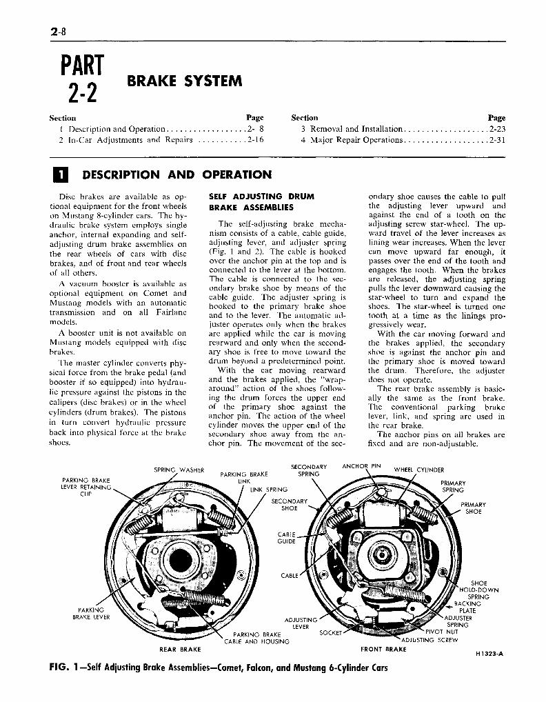
SELF ADJUSTING DRUMBRAKE ASSEMBLIES
The self-adjusting brake mecha-nism consists of a cable, cable guide,adjusting lever, and adjuster spring(Fig. 1 and 2). The cable is hookedover the anchor pin at the top and isconnected to the lever at the bottom.The cable is connected to the sec-ondary brake shoe by means of thecable guide. The adjuster spring ishooked to the primary brake shoeand to the lever. The automatic ad-juster operates only when the brakesare applied while the car is movingrearward and only when the second-ary shoe is free to move toward thedrum beyond a predetermined point.
With the car moving rearwardand the brakes applied, the "wrap-around" action of the shoes follow-ing the drum forces the upper endof the primary shoe against theanchor pin. The action of the wheelcylinder moves the upper end of thesecondary shoe away from the an-chor pin. The movement of the sec-
ondary shoe causes the cable to pullthe adjusting lever upward andagainst the end of a tooth on theadjusting screw star-wheel. The up-ward travel of the lever increases aslining wear increases. When the levercan move upward far enough, itpasses over the end of the tooth andengages the tooth. When the brakesare released, the adjusting springpulls the lever downward causing thestar-wheel to turn and expand theshoes. The star-wheel is turned onetooth at a time as the linings pro-gressively wear.
With the car moving forward andthe brakes applied, the secondaryshoe is against the anchor pin andthe primary shoe is moved towardthe drum. Therefore, the adjusterdoes not operate.
The rear brake assembly is basic-ally the same as the front brake.The conventional parking brakelever, link, and spring are used inthe rear brake.
The anchor pins on all brakes arefixed and are non-adjustable.
SPRING WASHER
PARKING BRAKELEVER RETAINING
CLIP
PARKING BRAKELINK
LINK SPRING
SECONDARYSPRING
ANCHOR PINWHEEL CYLINDER
CABLE
ADJUSTINGLEVER
PARKING BRAKECABLE AND HOUSING
PRIMARYSHOE
SOCKET
SHOEHOLD-DOWN
SPRINGBACKING
PLATEADJUSTERSPRING
PIVOT NUT
REAR BRAKE
'ADJUSTING SCREW
FRONT BRAKEH1323-A
F I G . 1 — Self Adjusting Brake Assemblies—Comet, Falcon, and Mustang 6-Cylinder Cars
P A R T 2 - 2 - BRAKE SYSTEM 2-9
CABLE ANCHOR
CABLE GUIDE
PARKING BRAKE LEVERRETAINING CLIP WASHER
PARKING BRAKE LINK
LINK SPRING
PRIMARY SHOE
AUTOMATIC ADJUSTERSPRING
CABLE
SECONDARY SHOE-TO- ANCHOR SPRING
SECONDARY SHOE PIVOT NUT
SOCKET ' ADJUSTING SCREW
FRONT BRAKE
CABLE HOOK
PRIMARY SHOE
°IVOT HOOK
ADJUSTING LEVER
PARKING BRAKE CABLE AND HOUSING*
PARKING BRAKECABLE HOUSING
RETAINING GROMMET
AUTOMATIC ADJUSTER SPRING
REAR BRAKE H122O-A
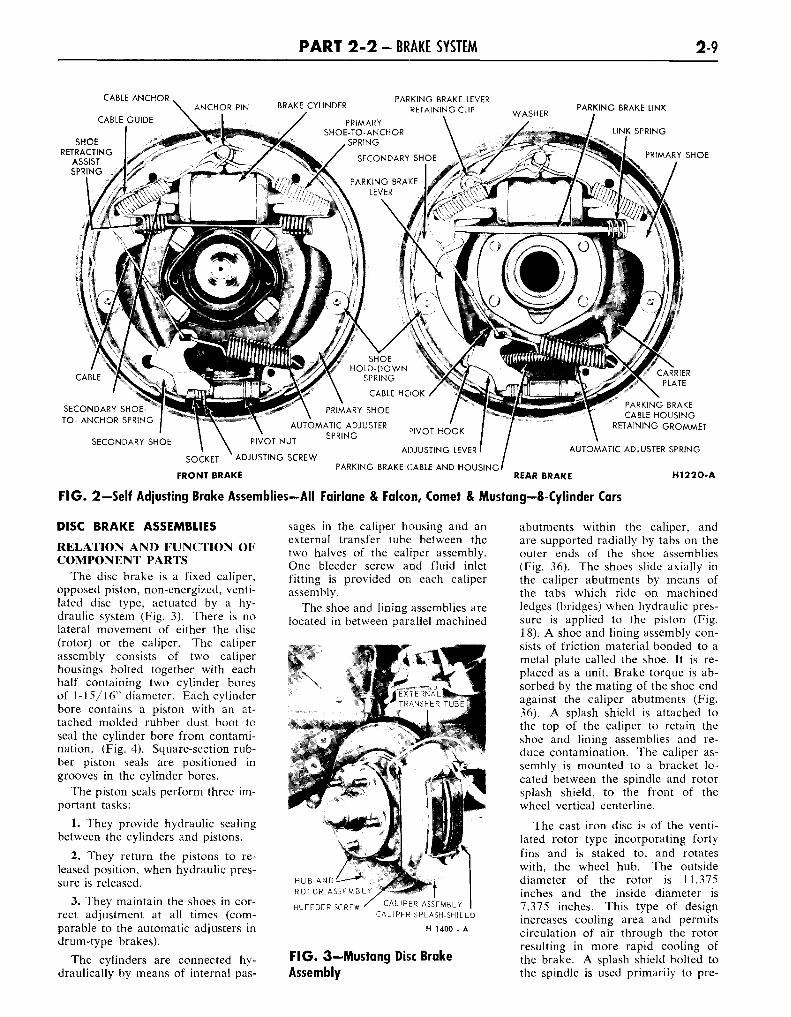
FIG. 2—Self Adjusting Brake Assemblies—All Fairlane & Falcon, Comet & Mustang—8-Cylinder Cars
DISC BRAKE ASSEMBLIES
RELATION AND FUNCTION OFCOMPONENT PARTS
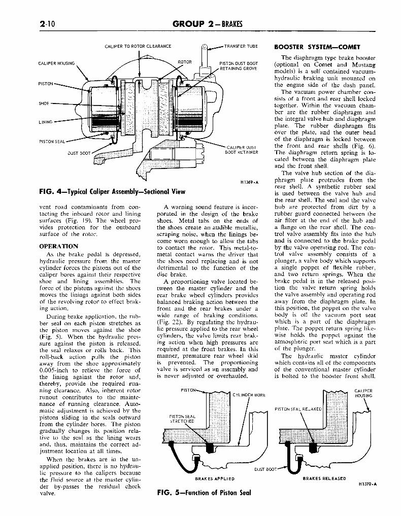
The disc brake is a fixed caliper,opposed piston, non-energized, venti-lated disc type, actuated by a hy-draulic system (Fig. 3). There is nolateral movement of either the disc(rotor) or the caliper. The caliperassembly consists of two caliperhousings bolted together with eachhalf containing two cylinder boresof 1-15/16" diameter. Each cylinderbore contains a piston with an at-tached molded rubber dust boot toseal the cylinder bore from contami-nation. (Fig. 4). Square-section rub-ber piston seals are positioned ingrooves in the cylinder bores.
The piston seals perform three im-portant tasks:
1. They provide hydraulic sealingbetween the cylinders and pistons.
2. They return the pistons to re-leased position, when hydraulic pres-sure is released.
3. They maintain the shoes in cor-rect adjustment at all times (com-parable to the automatic adjusters indrum-type brakes).
The cylinders are connected hy-draulically by means of internal pas-
sages in the caliper housing and anexternal transfer tube between thetwo halves of the caliper assembly.One bleeder screw and fluid inletfitting is provided on each caliperassembly.
The shoe and lining assemblies arelocated in between parallel machined
HUB AND:ROTOR ASSEMBLY^
BLEEDER SCREW ' CALIPER ASSEMBLYCALIPER SPLASH-SHIELD
H 1400 - A
FIG. 3—Mustang Disc BrakeAssembly
abutments within the caliper, andare supported radially by tabs on theouter ends of the shoe assemblies(Fig. 36). The shoes slide axially inthe caliper abutments by means ofthe tabs which ride on machinedledges (bridges) when hydraulic pres-sure is applied to the piston (Fig.18). A shoe and lining assembly con-sists of friction material bonded to ametal plate called the shoe. It is re-placed as a unit. Brake torque is ab-sorbed by the mating of the shoe endagainst the caliper abutments (Fig.36). A splash shield is attached tothe top of the caliper to retain theshoe and lining assemblies and re-duce contamination. The caliper as-sembly is mounted to a bracket lo-cated between the spindle and rotorsplash shield, to the front of thewheel vertical centerline.
The cast iron disc is of the venti-lated rotor type incorporating fortyfins and is staked to, and rotateswith, the wheel hub. The outsidediameter of the rotor is 11.375inches and the inside diameter is7.375 inches. This type of designincreases cooling area and permitscirculation of air through the rotorresulting in more rapid cooling ofthe brake. A splash shield bolted tothe spindle is used primarily to pre-
2-10 G R O U P 2-BRAKES
CALIPER TO ROTOR CLEARANCE
CALIPER HOUSING
PISTON
SHOE
LINING
PISTON SEAL
TRANSFER TUBE
PISTON DUST BOOTRETAINING GROVE
CALIPER DUSTBOOT RETAINER
HI 369. A
F I G . 4—Typical Caliper Assembly—Sectional View
vent road contaminants from con-tacting the inboard rotor and liningsurfaces (Fig. 19). The wheel pro-vides protection for the outboardsurface of the rotor.
OPERATIONAs the brake pedal is depressed,
hydraulic pressure from the mastercylinder forces the pistons out of thecaliper bores against their respectiveshoe and lining assemblies. Theforce of the pistons against the shoesmoves the linings against both sidesof the revolving rotor to effect brak-ing action.
During brake application, the rub-ber seal on each piston stretches asthe piston moves against the shoe(Fig. 5). When the hydraulic pres-sure against the piston is released,the seal relaxes or rolls back. Thisroll-back action pulls the pistonaway from the shoe approximately0.005-inch to relieve the force ofthe lining against the rotor and,thereby, provide the required run-ning clearance. Also, inherent rotorrunout contributes to the mainte-nance of running clearance. Auto-matic adjustment is achieved by thepistons sliding in the seals outwardfrom the cylinder bores. The pistongradually changes its position rela-tive to the seal as the lining wearsand, thus, maintains the correct ad-justment location at all times.
When the brakes are in the un-applied position, there is no hydrau-lic pressure to the calipers becausethe fluid source at the master cylin-der by-passes the residual checkvalve.
A warning sound feature is incor-porated in the design of the brakeshoes. Metal tabs on the ends ofthe shoes create an audible metallic,scraping noise, when the linings be-come worn enough to allow the tabsto contact the rotor. This metal-to-metal contact warns the driver thatthe shoes need replacing and is notdetrimental to the function of thedisc brake.
A proportioning valve located be-tween the master cylinder and therear brake wheel cylinders providesbalanced braking action between thefront and the rear brakes under awide range of braking conditions.(Fig. 22). By regulating the hydrau-lic pressure applied to the rear wheelcylinders, the valve limits rear brak-ing action when high pressures arerequired at the front brakes. In thismanner, premature rear wheel skidis prevented. The proportioningvalve is serviced as an assembly andis never adjusted or overhauled.
PISTON
BOOSTER SYSTEM—COMET
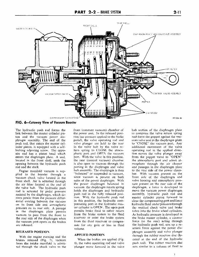
The diaphragm type brake booster(optional on Comet and Mustangmodels) is a self contained vacuum-hydraulic braking unit mounted onthe engine side of the dash panel.
The vacuum power chamber con-sists of a front and rear shell lockedtogether. Within the vacuum cham-ber are the rubber diaphragm andthe integral valve hub and diaphragmplate. The rubber diaphragm fitsover the plate, and the outer beadof the diaphragm is locked betweenthe front and rear shells (Fig. 6).The diaphragm return spring is lo-cated between the diaphragm plateand the front shell.
The valve hub section of the dia-phragm plate protrudes from therear shell. A synthetic rubber sealis used between the valve hub andthe rear shell. The seal and the valvehub are protected from dirt by arubber guard connected between theair filter at the end of the hub anda flange on the rear shell. The con-trol valve assembly fits into the huband is connected to the brake pedalby the valve operating rod. The con-trol valve assembly consists of aplunger, a valve body which supportsa single poppet of flexible rubber,and two return springs. When thebrake pedal is in the released posi-tion the valve return spring holdsthe valve assembly and operating rodaway from the diaphragm plate. Inthis position, the poppet on the valvebody is off the vacuum port seatwhich is a part of the diaphragmplate. The poppet return spring like-wise holds the poppet against theatmospheric port seat which is a partof the plunger.
The hydraulic master cylinderwhich contains all of the componentsof the conventional master cylinderis bolted to the booster front shell.
BRAKES APPLIED BRAKES RELEASEDHI 370-A
F IG . 5—Function of Piston Seal
P A R T 2 - 2 - BRAKE SYSTEM 2-11
REAR SHELLFRONT SHELL
MASTER CYLINDER
DIAPHRAGM PLATE AND VALVE HUB ASSEMBLY
DIAPHRAGM
DIAPHRAGM RETURN SPRING H1324-B
F IG . 6—Cutaway View of Vacuum Booster
The hydraulic push rod forms thelink between the master cylinder pis-ton and the vacuum power dia-phragm assembly. The end of thepush rod, that enters the master cyl-inder piston, is equipped with a self-locking adjusting screw. The oppo-site end has a piston head whichenters the diaphragm plate. A seal,located in the front shell, seals theopening between the hydraulic pushrod and the shell.
Engine manifold vacuum is sup-plied to the booster through avacuum check valve located in thefront shell. Air is admitted throughthe air filter located at the end ofthe valve hub. The hydraulic pushrod is actuated by pedal pressureassisted by the diaphragm, which de-rives power from the pressure differ-ential existing between the vacuumon its front side and atmosphericpressure on its rear side. A passagein the diaphragm plate permitsvacuum to pass from the front tothe rear side of the diaphragm whenthe vacuum port opens as the brakesare released.
RELEASED POSITION
With the engine running and thebrakes released (Fig. 7), vacuumfrom the intake manifold is admit-ted through the check valve to the
front (constant vacuum) chamber ofthe power unit. In the released posi-tion (no pressure applied to the brakepedal), the valve operating rod andvalve plunger are held to the rearin the valve hub by the valve re-turn spring to CLOSE the atmos-pheric port and OPEN the vacuumport. With the valve in this position,the rear (control vacuum) chamberis also open to vacuum through theporting in the diaphragm and valvehub assembly. The diaphragm is then"balanced" or suspended in vacuum,since vacuum is present on bothsides of the power diaphragm. Withthe power diaphragm balanced invacuum, the diaphragm return springholds the diaphragm and hydraulicpush rod in the fully released posi-tion. With the hydraulic push rodin this position, the hydraulic com-pensating port in the hydraulic mas-ter cylinder is OPEN . The open portpermits brake fluid to either returnfrom the brake system to the fluidreservoir or enter the brake systemfrom the fluid reservoir to compen-sate for any gain or loss in fluidvolume.
APPLIED POSITIONWhen the brakes are applied (Fig.
8), the valve operating rod and valveplunger move forward in the valve
hub section of the diaphragm plateto compress the valve return springand force the poppet against the vac-uum valve seat in the diaphragm plateto "CLOSE" the vacuum port. Anyadditional movement of the valveoperating rod in the applied direc-tion moves the valve plunger awayfrom the poppet valve to "OPEN"the atmospheric port and admit at-mosphere through the air cleanerand passages in the diaphragm plateto the rear side of the power cham-ber. With vacuum present on thefront side of the diaphragm andvalve housing and atmospheric pres-sure present on the rear side of thediaphragm, a force is developed tomove the vacuum power diaphragmassembly, hydraulic push rod andmaster cylinder piston forward toclose the compensating port and forcehydraulic fluid underpressure throughthe residual check valve and braketubes into the brake wheel cylinders.As hydraulic pressure is developed inthe brake master cylinder, a counterforce (to the rear) acting throughthe hydraulic push rod, sets up a re-action force against the power dia-phragm assembly and valve plungerthrough the rubber reaction disc (lo-cated at the end of the hydraulicpush rod). The rubber reaction discacts similar to a column of fluid to
2-12 G R O U P 2-BRAKES
VACUUM PORT OPEN
ATMOSPHERIC SOURCE
ATMOSPHERIC PORT CLOSED
VACUUM SOURCE
FIG. 7—Booster in Released Position
distribute the pressure between thevacuum power diaphragm assemblyand the valve plunger in proportionto their respective contact areas. Thepressure acting against the valveplunger and valve operating rodtends to move the valve plungerslightly to the rear in relation tothe diaphragm and valve hub assem-
H1325-A
bly to close off the atmosphericport. The driver is thus assured a"feel" of the brake, since part ofthe counter force reacts through thevalve plunger, valve operating rod,and pedal linkage against the driver'sfoot. This reaction force is in directproportion to the hydraulic pressuredeveloped within the brake system.
VACUUM PORTCLOSED
ATMOSPHERIC SOURCE
ATMOSPHERIC PORT OPEN
VACUUM SOURCE
F IG . 8—Booster in Applied Position
Hi 326-A
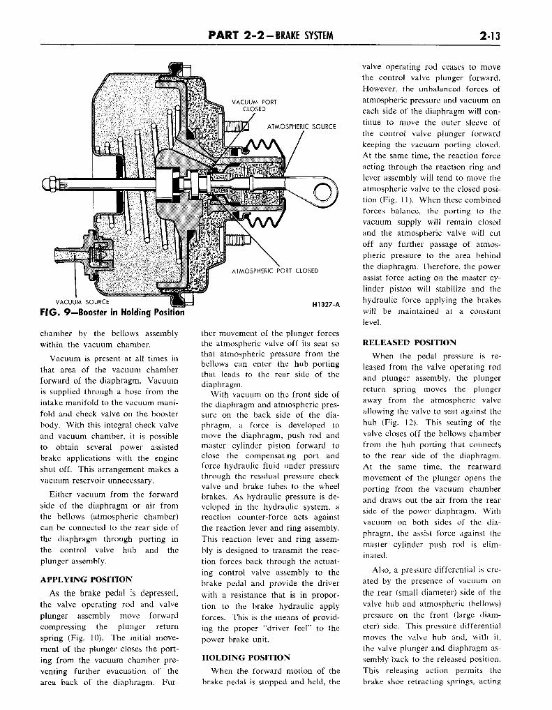
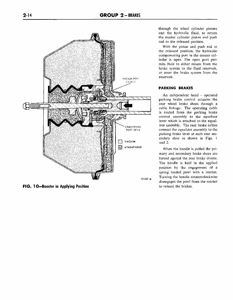
HOLDING POSITIONDuring brake application, the "re-
action" force which opposes theforce applied by the driver, tends toclose the atmospheric port. Whenboth atmospheric and vacuum portsare CLOSED, the booster is said tobe in the holding position (Fig. 9).With both valves closed, any degreeof brake application attained will beheld until either the atmosphericport is reopened by an increase inpedal pressure to further increasethe brake application or by a de-crease in pedal pressure to reopenthe vacuum port to decrease thebrake application. Whenever thepressure applied to the brake pedalis held constant for a moment, thevalve returns to its holding position.However, upon reaching the fullyapplied position the force appliedto the brake pedal overrules the re-action force. In this position thevalve plunger and atmospheric valveseat are held away from the valvepoppet to admit maximum atmos-pheric pressure to the rear chamber.With the front chamber open tomanifold vacuum, full power appli-cation is attained which is referredto as the "run-out" of the powerunit. Any increase in hydraulic pres-sure beyond this point must be sup-plied by physical effort of the driver.
NO POWER CONDITIONIt should be noted that in case
of engine failure and consequent lossof engine vacuum, at least one fullpower brake application may bemade from the vacuum in thebooster. With the engine off and novacuum in the power system, thebrakes can be applied in the conven-tional manner by applying more phy-sical effort to the brake pedal.
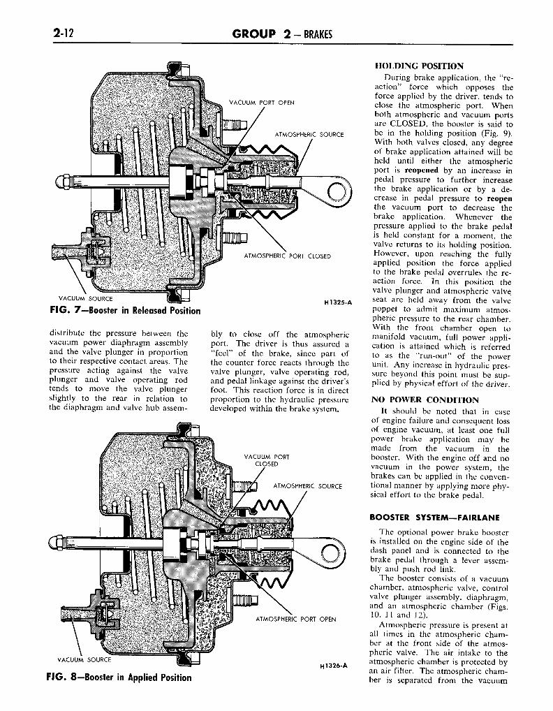
BOOSTER SYSTEM—FAIRLANE
The optional power brake boosteris installed on the engine side of thedash panel and is connected to thebrake pedal through a lever assem-bly and push rod link.
The booster consists of a vacuumchamber, atmospheric valve, controlvalve plunger assembly, diaphragm,and an atmospheric chamber (Figs.10, 11 and 12).
Atmospheric pressure is present atall times in the atmospheric cham-ber at the front side of the atmos-pheric valve. The air intake to theatmospheric chamber is protected byan air filter. The atmospheric cham-ber is separated from the vacuum
PART 2-2-BRAKE SYSTEM 2-13
ATMOSPHERIC SOURCE
ATMOSPHERIC PORT CLOSED
VACUUM SOURCE
FIG. 9—Booster in Holding Position
chamber by the bellows assemblywithin the vacuum chamber.
Vacuum is present at all times inthat area of the vacuum chamberforward of the diaphragm. Vacuumis supplied through a hose from theintake manifold to the vacuum mani-fold and check valve on the boosterbody. With this integral check valveand vacuum chamber, it is possibleto obtain several power assistedbrake applications with the engineshut off. This arrangement makes avacuum reservoir unnecessary.
Either vacuum from the forwardside of the diaphragm or air fromthe bellows (atmospheric chamber)can be connected to the rear side ofthe diaphragm through porting inthe control valve hub and theplunger assembly.
APPLYING POSITION
As the brake pedal is depressed,the valve operating rod and valveplunger assembly move forwardcompressing the plunger returnspring (Fig. 10). The initial move-ment of the plunger closes the port-ing from the vacuum chamber pre-venting further evacuation of thearea back of the diaphragm. Fur-
H1327-A
ther movement of the plunger forcesthe atmospheric valve off its seat sothat atmospheric pressure from thebellows can enter the hub portingthat leads to the rear side of thediaphragm.
With vacuum on the front side ofthe diaphragm and atmospheric pres-sure on the back side of the dia-phragm, a force is developed tomove the diaphragm, push rod andmaster cylinder piston forward toclose the compensating port andforce hydraulic fluid under pressurethrough the residual pressure checkvalve and brake tubes to the wheelbrakes. As hydraulic pressure is de-veloped in the hydraulic system, areaction counter-force acts againstthe reaction lever and ring assembly.This reaction lever and ring assem-bly is designed to transmit the reac-tion forces back through the actuat-ing control valve assembly to thebrake pedal and provide the driverwith a resistance that is in propor-tion to the brake hydraulic applyforces. This is the means of provid-ing the proper "driver feel" to thepower brake unit.
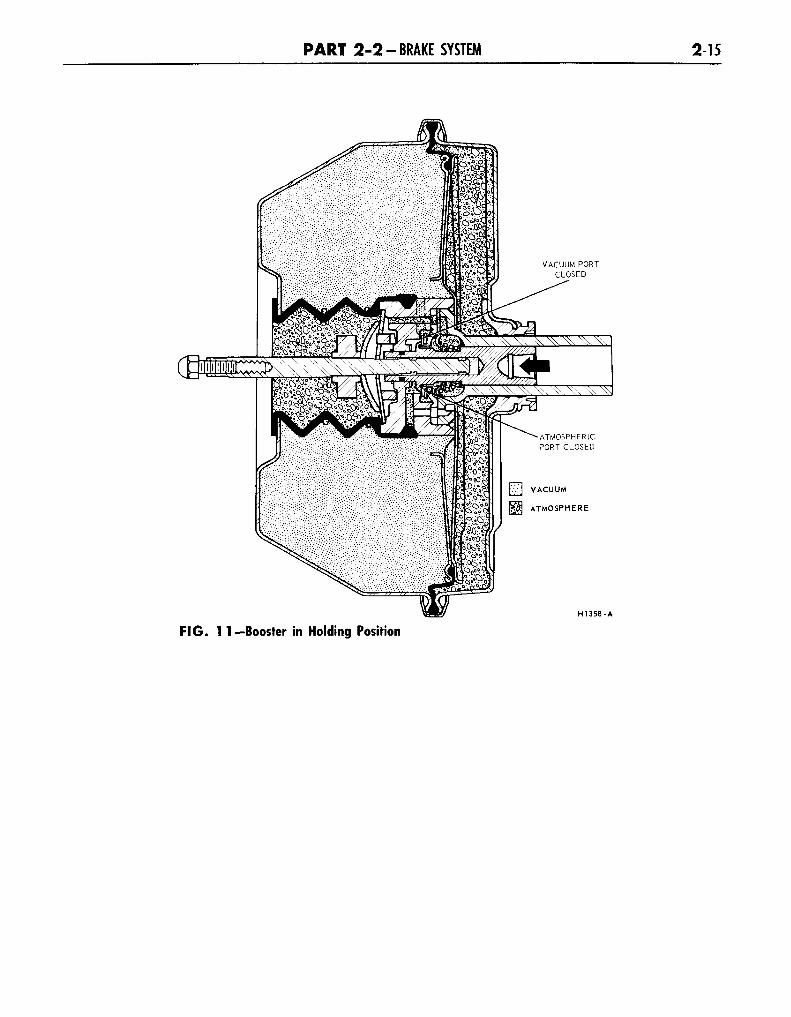
HOLDING POSITION
When the forward motion of thebrake pedal is stopped and held, the
valve operating rod ceases to movethe control valve plunger forward.However, the unbalanced forces ofatmospheric pressure and vacuum oneach side of the diaphragm will con-tinue to move the outer sleeve ofthe control valve plunger forwardkeeping the vacuum porting closed.At the same time, the reaction forceacting through the reaction ring andlever assembly will tend to move theatmospheric valve to the closed posi-tion (Fig. 11). When these combinedforces balance, the porting to thevacuum supply will remain closedand the atmospheric valve will cutoff any further passage of atmos-pheric pressure to the area behindthe diaphragm. Therefore, the powerassist force acting on the master cy-linder piston will stabilize and thehydraulic force applying the brakeswill be maintained at a constantlevel.
RELEASED POSITION
When the pedal pressure is re-leased from the valve operating rodand plunger assembly, the plungerreturn spring moves the plungeraway from the atmospheric valveallowing the valve to seat against thehub (Fig. 12). This seating of thevalve closes off the bellows chamberfrom the hub porting that connectsto the rear side of the diaphragm.At the same time, the rearwardmovement of the plunger opens theporting from the vacuum chamberand draws out the air from the rearside of the power diaphragm. Withvacuum on both sides of the dia-phragm, the assist force against themaster cylinder push rod is elim-inated.
Also, a pressure differential is cre-ated by the presence of vacuum onthe rear (small diameter) side of thevalve hub and atmospheric (bellows)pressure on the front (large diam-eter) side. This pressure differentialmoves the valve hub and, with it,the valve plunger and diaphragm as-sembly back to the released position.This releasing action permits thebrake shoe retracting springs, acting
2-14 G R O U P 2-BRAKES
H1357-A
F I G . 10—Booster in Applying Position
through the wheel cylinder pistonsand the hydraulic fluid, to returnthe master cylinder piston and pushrod to the released position.
With the piston and push rod inthe released position, the hydrauliccompensating port in the master cyl-inder is open. The open port per-mits fluid to either return from thebrake system to the fluid reservoir,or enter the brake system from thereservoir.
PARKING BRAKES
An independent hand - operatedparking brake control actuates therear wheel brake shoes through acable linkage. The operating cableis routed from the parking brakecontrol assembly to the equalizerlever which is attached to the equal-izer assembly. The rear brake cablesconnect the equalizer assembly to theparking brake lever at each rear sec-ondary shoe as shown in Figs. 1and 2.
When the handle is pulled the pri-mary and secondary brake shoes areforced against the rear brake drums.The handle is held in the appliedposition by the engagement of aspring loaded pawl with a ratchet.Turning the handle counterclockwisedisengages the pawl from the ratchetto release the brakes.
PART 2-2-BRAKE SYSTEM 2-15
VACUUM PORTCLOSED
H1358-A
FIG. 1 1 — Booster in Holding Position
2-16 G R O U P 2-BRAKES
ATMOSPHERICPORT CLOSED
VACUUM
ATMOSPHERE
H1359-A
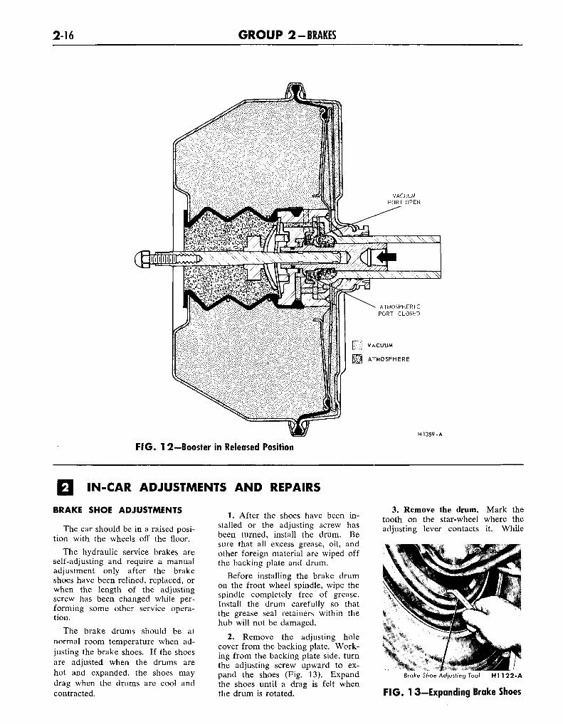
FIG. 1 2—Booster in Released Position
IN-CAR ADJUSTMENTS AND REPAIRS
BRAKE SHOE ADJUSTMENTS
The car should be in a raised posi-tion with the wheels off the floor.
The hydraulic service brakes areself-adjusting and require a manualadjustment only after the brakeshoes have been relined, replaced, orwhen the length of the adjustingscrew has been changed while per-forming some other service opera-tion.
The brake drums should be atnormal room temperature when ad-justing the brake shoes. If the shoesare adjusted when the drums arehot and expanded, the shoes maydrag when the drums are cool andcontracted.
1. After the shoes have been in-stalled or the adjusting screw hasbeen turned, install the drum. Besure that all excess grease, oil, andother foreign material are wiped offthe backing plate and drum.
Before installing the brake drumon the front wheel spindle, wipe thespindle completely free of grease.Install the drum carefully so thatthe grease seal retainers within thehub will not be damaged.
2. Remove the adjusting holecover from the backing plate. Work-ing from the backing plate side, turnthe adjusting screw upward to ex-pand the shoes (Fig. 13). Expandthe shoes until a drag is felt whenthe drum is rotated.
3. Remove the drum. Mark thetooth on the star-wheel where theadjusting lever contacts it. While
Brake Shoe Adjusting Tool HI 1 22-A
F IG . 13—Expanding Brake Shoes