Embed Size (px)
Citation preview
Demystifying EnterpriseFiber Networks
Adrian YoungLeviton Network Solutions
In this session• Multimode fiber types – distance matters• How many fibers do I need for my application?
– 2, 4, 8, 12, 16, 24 or 32?
• Current/Future IEEE and non IEEE applications– Will my existing fiber plant support these?
• Connectivity choices and conversion cassettes
FIBER TYPESDistance matters
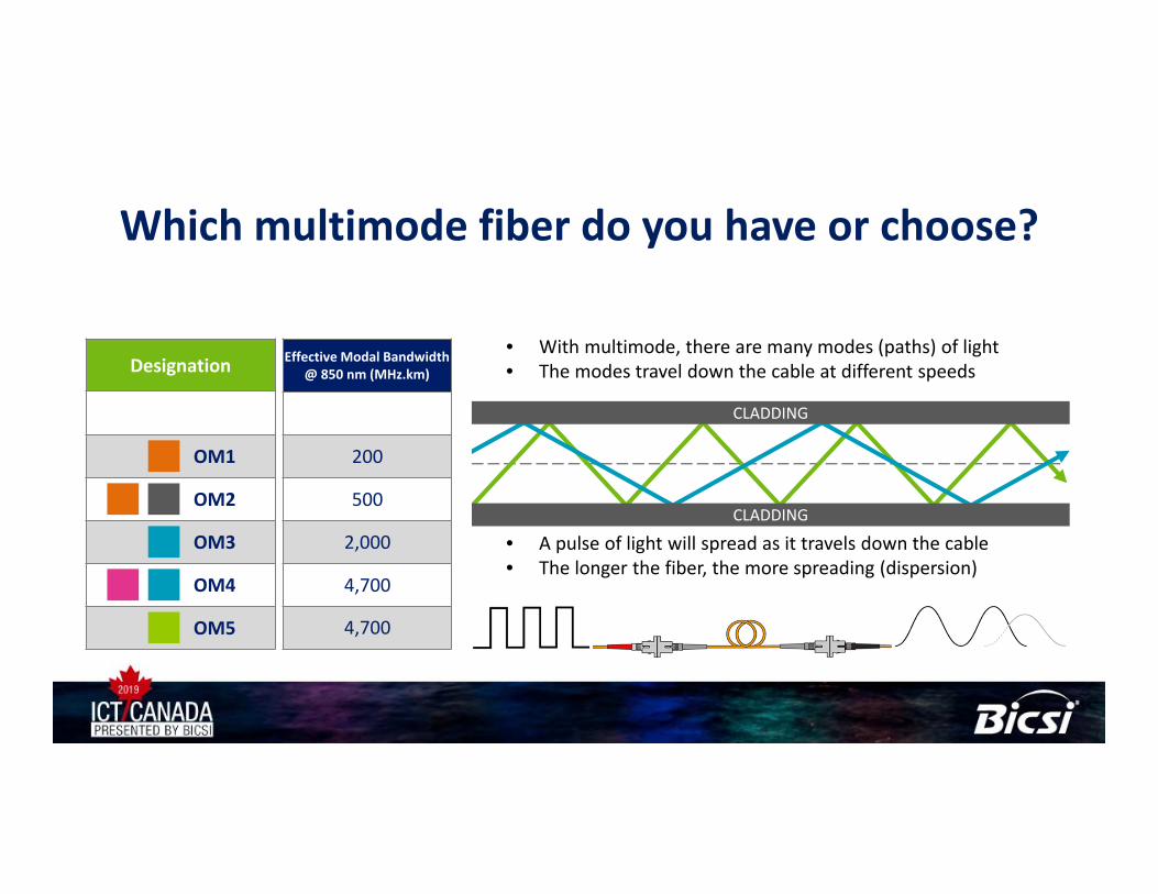
Which multimode fiber do you have or choose?
• With multimode, there are many modes (paths) of light• The modes travel down the cable at different speeds
• A pulse of light will spread as it travels down the cable• The longer the fiber, the more spreading (dispersion)
Designation Effective Modal Bandwidth @ 850 nm (MHz.km)
OM1
OM2
OM3
OM4
OM5
CLADDING
CLADDING
200
500
2,000
4,700
4,700
Effective Modal Bandwidth @ 850 nm (MHz.km)Designation
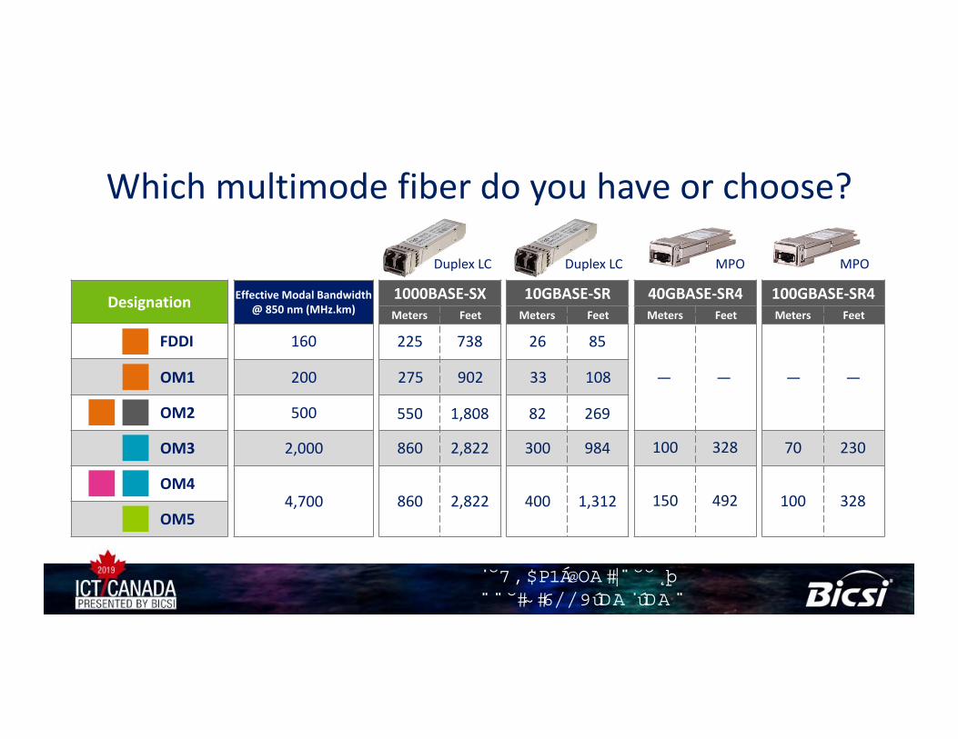
Which multimode fiber do you have or choose?
Duplex LC Duplex LC MPO MPO
100GBASE‐SR4Meters Feet
200
500
2,000
160FDDI
1000BASE‐SXMeters Feet
10GBASE‐SRMeters Feet
40GBASE‐SR4Meters Feet
OM2
OM3
225 738
275 902
550 1,808
860 2,822
860 2,822
26 85
33 108
82 269
300 984
400 1,312
100 328
150 492
— — — —
70 230
100 328OM4
OM1
OM54,700
��������� ��������� � ������� ���� �
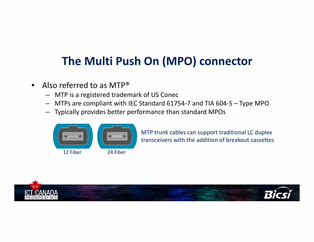
The Multi Push On (MPO) connector
• Also referred to as MTP®– MTP is a registered trademark of US Conec– MTPs are compliant with IEC Standard 61754‐7 and TIA 604‐5 – Type MPO– Typically provides better performance than standard MPOs
MTP trunk cables can support traditional LC duplex transceivers with the addition of breakout cassettes
24 Fiber12 Fiber
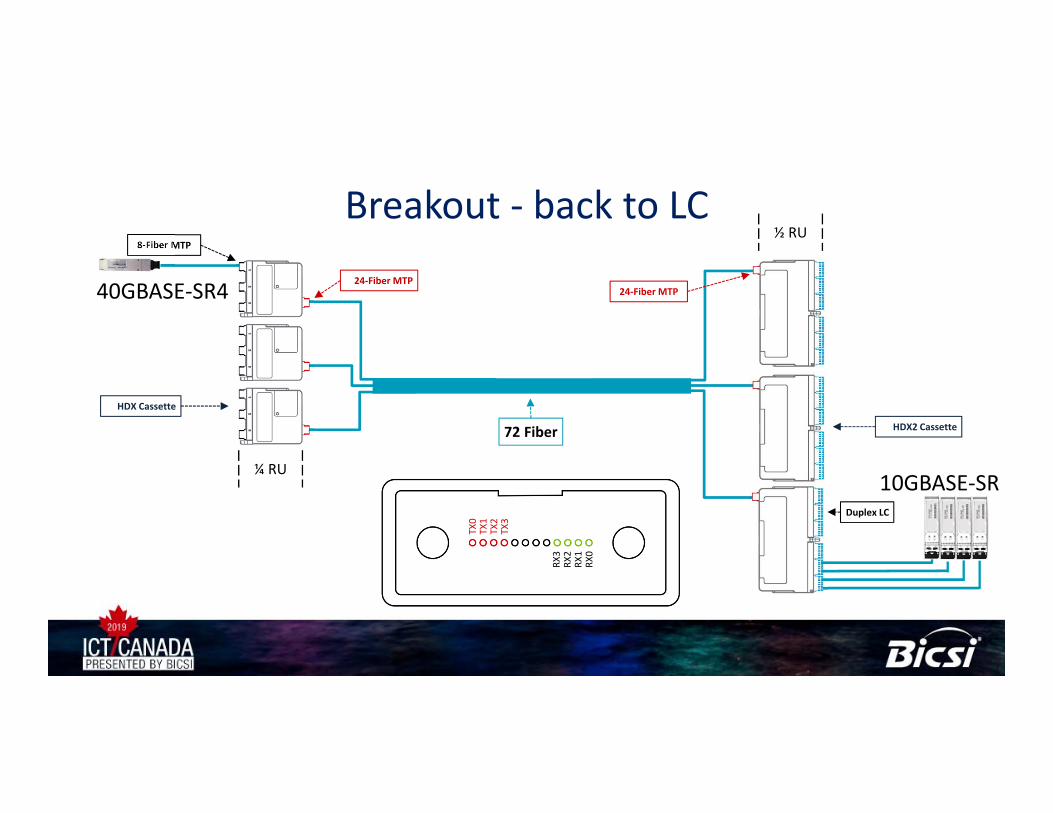
Breakout ‐ back to LC
Duplex LC
HDX2 Cassette
HDX Cassette
24‐Fiber MTP
8‐Fiber MTP
24‐Fiber MTP
¼ RU
½ RU
72 Fiber
40GBASE‐SR4
10GBASE‐SRTX0
TX1
TX2
TX3
RX3
RX2
RX1
RX0
Duplex SFP
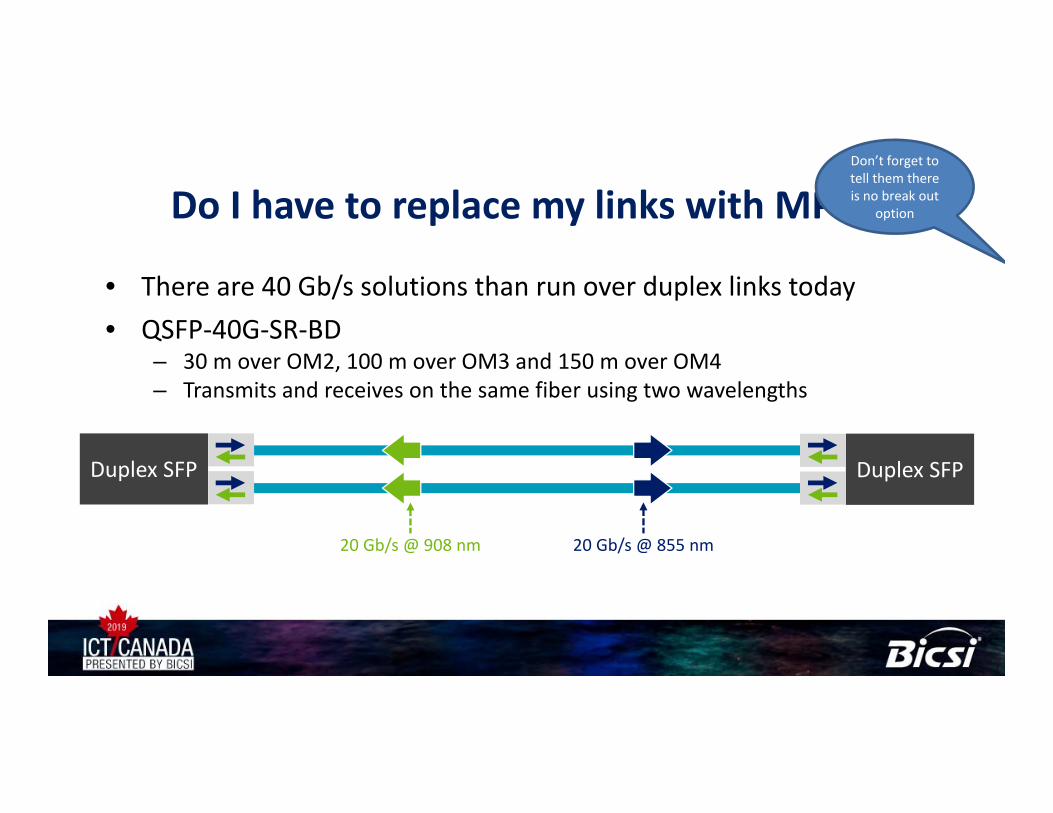
Do I have to replace my links with MPO?
• There are 40 Gb/s solutions than run over duplex links today• QSFP‐40G‐SR‐BD
– 30 m over OM2, 100 m over OM3 and 150 m over OM4– Transmits and receives on the same fiber using two wavelengths
Duplex SFP
20 Gb/s @ 908 nm 20 Gb/s @ 855 nm
Don’t forget to tell them there is no break out
option
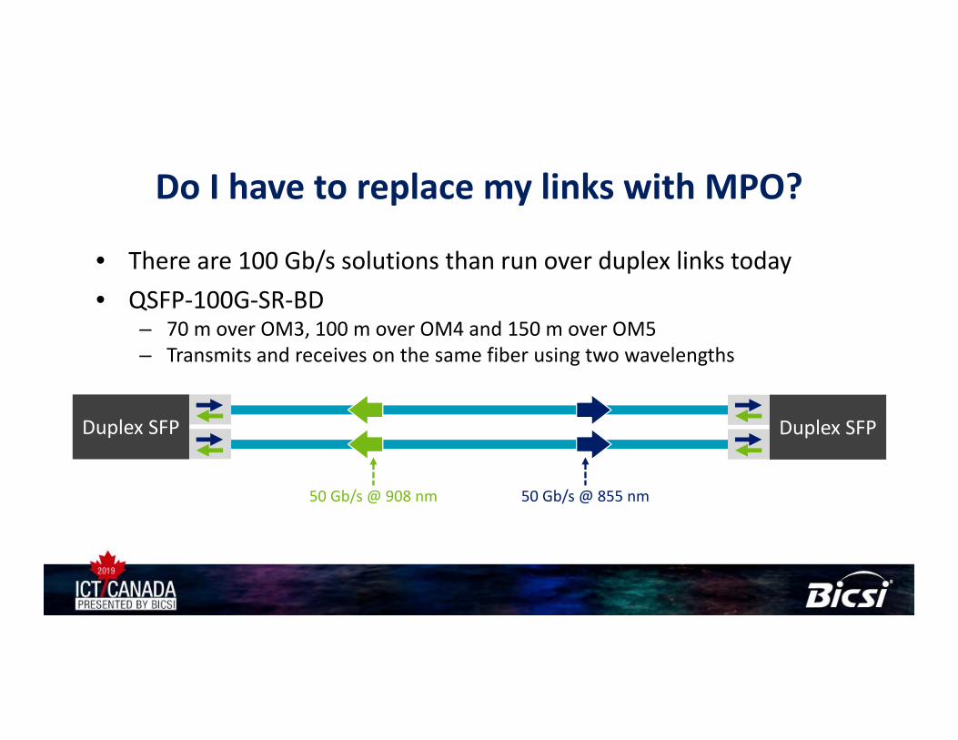
Do I have to replace my links with MPO?
• There are 100 Gb/s solutions than run over duplex links today• QSFP‐100G‐SR‐BD
– 70 m over OM3, 100 m over OM4 and 150 m over OM5– Transmits and receives on the same fiber using two wavelengths
Duplex SFP Duplex SFP
50 Gb/s @ 908 nm 50 Gb/s @ 855 nm
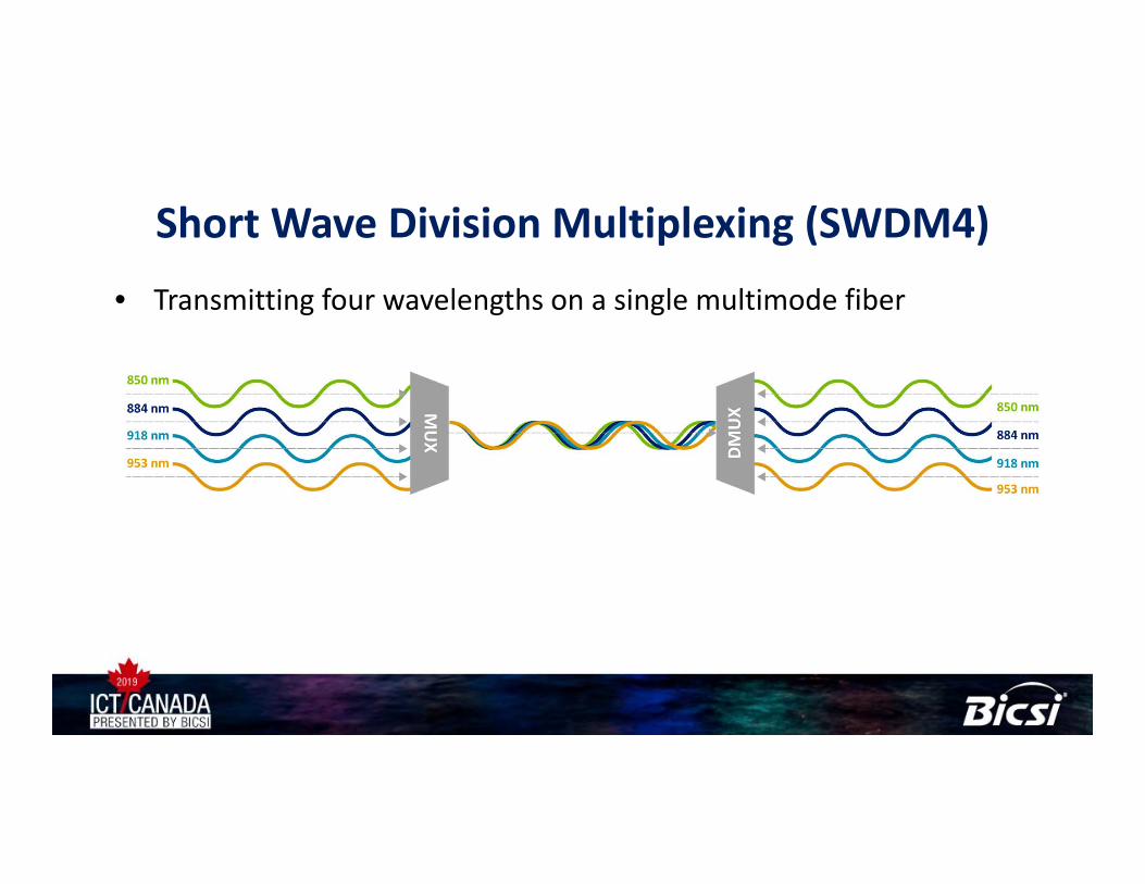
Short Wave Division Multiplexing (SWDM4)• Transmitting four wavelengths on a single multimode fiber
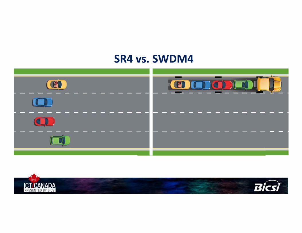
SR4 vs. SWDM4
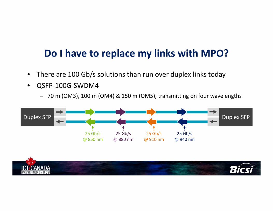
Do I have to replace my links with MPO?
• There are 100 Gb/s solutions than run over duplex links today• QSFP‐100G‐SWDM4
– 70 m (OM3), 100 m (OM4) & 150 m (OM5), transmitting on four wavelengths
25 Gb/s @ 850 nm
25 Gb/s @ 940 nm
25 Gb/s @ 880 nm
25 Gb/s @ 910 nm
Duplex SFP Duplex SFP
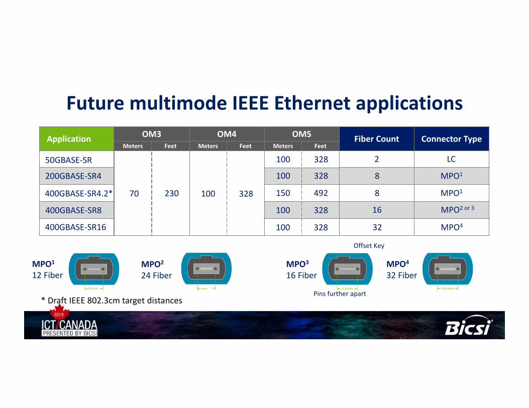
Future multimode IEEE Ethernet applicationsApplication OM3 OM4 OM5 Fiber Count Connector Type
Meters Feet Meters Feet Meters FeetApplication OM3 OM4 OM5 Fiber Count Connector Type
Meters Feet Meters Feet Meters Feet
70 230 100 328
2 LC
8 MPO1
8 MPO1
16 MPO2 or 3
32 MPO4
200GBASE‐SR4
400GBASE‐SR4.2
400GBASE‐SR8
400GBASE‐SR16
MPO3
16 FiberMPO4
32 Fiber4.6 mm
MPO2
24 FiberMPO1
12 Fiber4.6 mm
Offset Key
Pins further apart
100 328
100 328
150 492
100 328
100 328
* Draft IEEE 802.3cm target distances
50GBASE‐SR
*
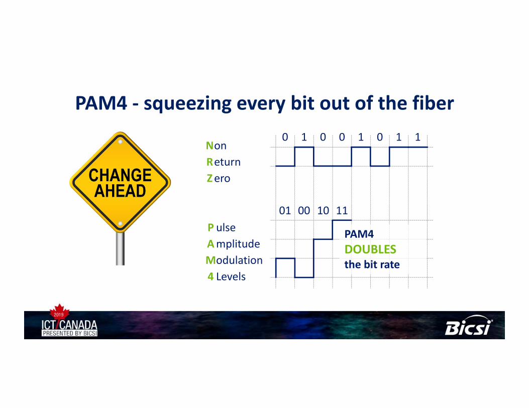
PAM4 ‐ squeezing every bit out of the fiber0 1 0 0 1 0 1 1
01 00 10 11
PAM4 DOUBLESthe bit rate
NonReturnZero
P ulseAmplitudeModulation4 Levels
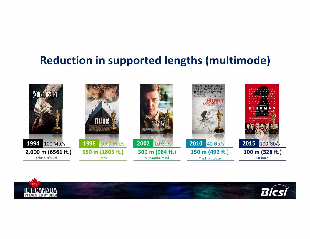
Reduction in supported lengths (multimode)
100 m (328 ft.) 2015 100 Gb/s
Birdman150 m (492 ft.) 2010 40 Gb/s
The Hurt Locker
300 m (984 ft.) 2002 10 Gb/s
A Beautiful Mind550 m (1805 ft.) 1998 1000 Mb/s
Titanic2,000 m (6561 ft.) 1994 100 Mb/s
Schindler’s List
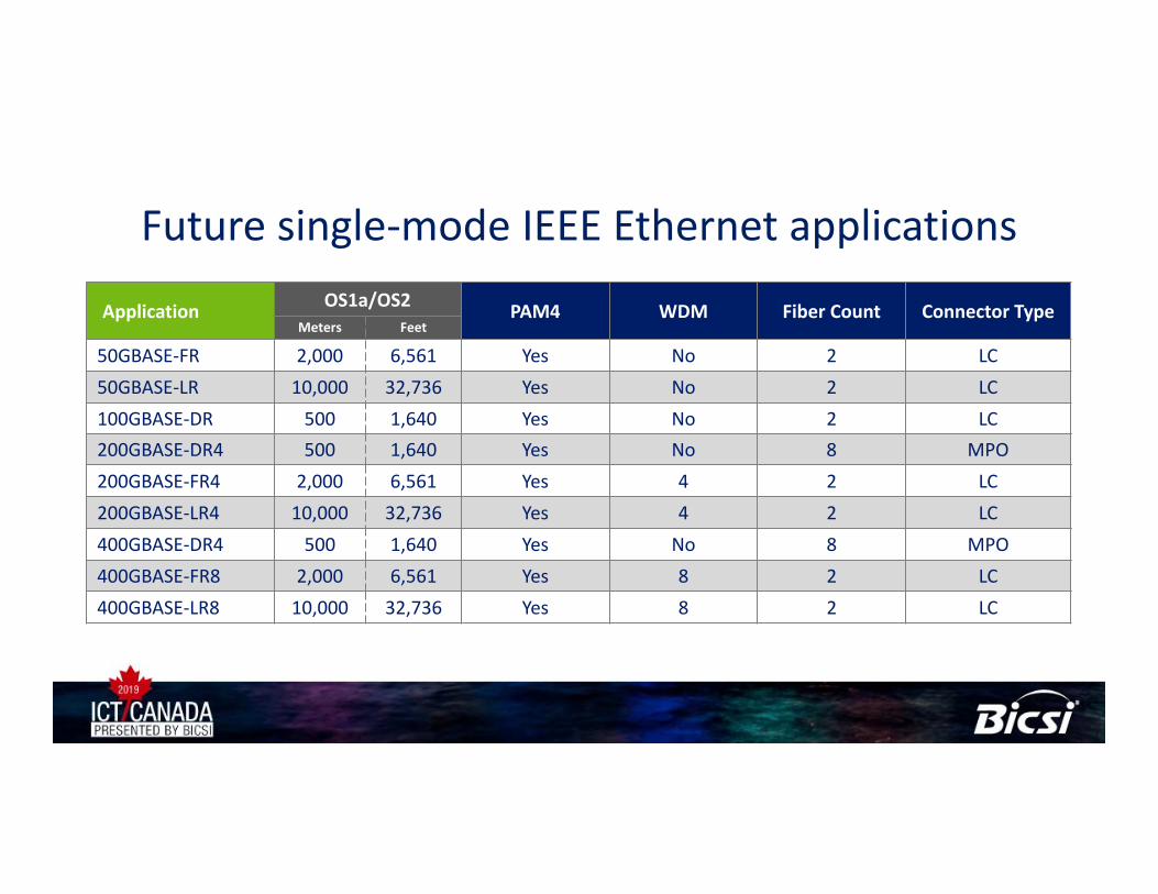
Future single‐mode IEEE Ethernet applications
Application OS1a/OS2 PAM4 WDM Fiber Count Connector TypeMeters Feet
50GBASE‐FR 2,000 6,561 Yes No 2 LC50GBASE‐LR 10,000 32,736 Yes No 2 LC100GBASE‐DR 500 1,640 Yes No 2 LC200GBASE‐DR4 500 1,640 Yes No 8 MPO200GBASE‐FR4 2,000 6,561 Yes 4 2 LC200GBASE‐LR4 10,000 32,736 Yes 4 2 LC400GBASE‐DR4 500 1,640 Yes No 8 MPO400GBASE‐FR8 2,000 6,561 Yes 8 2 LC400GBASE‐LR8 10,000 32,736 Yes 8 2 LC
CONNECTIVITY OPTIONSTermination options
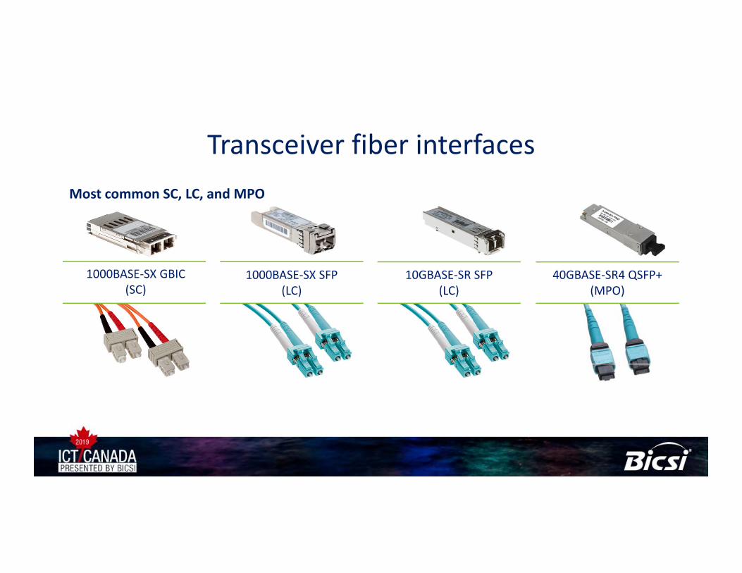
Transceiver fiber interfaces
1000BASE‐SX GBIC(SC)
1000BASE‐SX SFP(LC)
10GBASE‐SR SFP(LC)
40GBASE‐SR4 QSFP+(MPO)
Most common SC, LC, and MPO
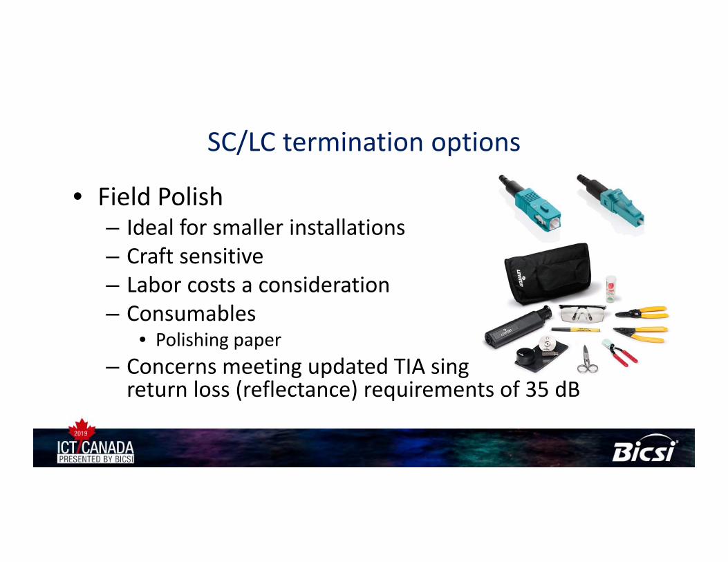
SC/LC termination options
• Field Polish– Ideal for smaller installations– Craft sensitive– Labor costs a consideration– Consumables
• Polishing paper– Concerns meeting updated TIA single‐modereturn loss (reflectance) requirements of 35 dB
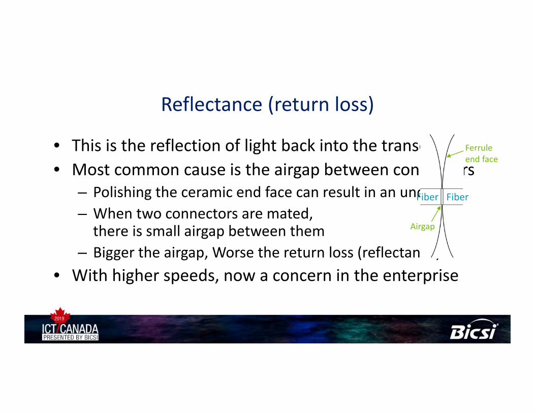
Reflectance (return loss)
• This is the reflection of light back into the transceiver• Most common cause is the airgap between connectors
– Polishing the ceramic end face can result in an undercut– When two connectors are mated,there is small airgap between them
– Bigger the airgap, Worse the return loss (reflectance)• With higher speeds, now a concern in the enterprise
Airgap
Ferrule end face
FiberFiber
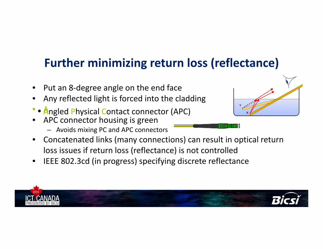
Angled Polish Connector (APC)Angled polish Connector (APC)Angled Physical Contact connector (APC)
Further minimizing return loss (reflectance)
• Put an 8‐degree angle on the end face• Any reflected light is forced into the cladding• A• APC connector housing is green
– Avoids mixing PC and APC connectors• Concatenated links (many connections) can result in optical return
loss issues if return loss (reflectance) is not controlled• IEEE 802.3cd (in progress) specifying discrete reflectance
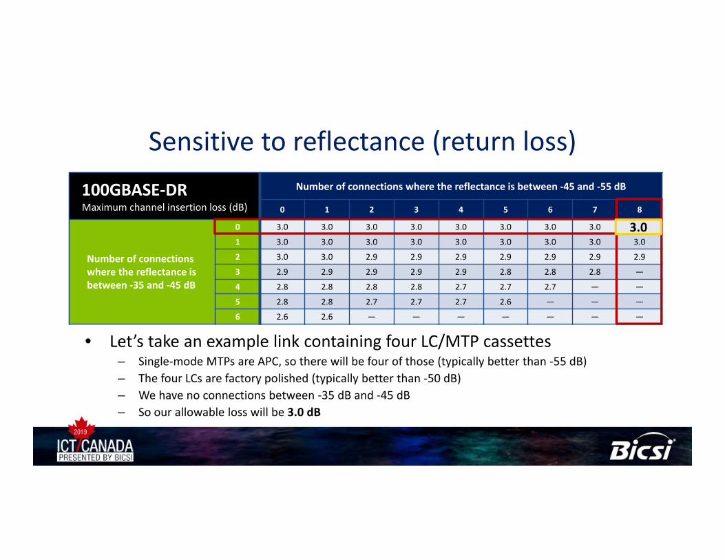
Sensitive to reflectance (return loss)
• Let’s take an example link containing four LC/MTP cassettes– Single‐mode MTPs are APC, so there will be four of those (typically better than ‐55 dB)– The four LCs are factory polished (typically better than ‐50 dB)– We have no connections between ‐35 dB and ‐45 dB– So our allowable loss will be 3.0 dB
100GBASE‐DRMaximum channel insertion loss (dB)
Number of connections where the reflectance is between ‐45 and ‐55 dB
0 1 2 3 4 5 6 7 8
0 3.0 3.0 3.0 3.0 3.0 3.0 3.0 3.0 3.0
1 3.0 3.0 3.0 3.0 3.0 3.0 3.0 3.0 3.0
2 3.0 3.0 2.9 2.9 2.9 2.9 2.9 2.9 2.9
3 2.9 2.9 2.9 2.9 2.9 2.8 2.8 2.8 —
4 2.8 2.8 2.8 2.8 2.7 2.7 2.7 — —
5 2.8 2.8 2.7 2.7 2.7 2.6 — — —
6 2.6 2.6 — — — — — — —
Number of connections where the reflectance is between ‐35 and ‐45 dB
3.0
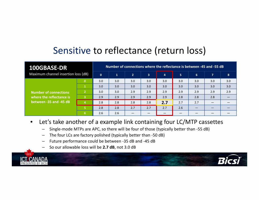
Sensitive to reflectance (return loss)
• Let’s take another of a example link containing four LC/MTP cassettes– Single‐mode MTPs are APC, so there will be four of those (typically better than ‐55 dB)– The four LCs are factory polished (typically better than ‐50 dB)– Future performance could be between ‐35 dB and ‐45 dB– So our allowable loss will be 2.7 dB, not 3.0 dB
100GBASE‐DRMaximum channel insertion loss (dB)
Number of connections where the reflectance is between ‐45 and ‐55 dB
0 1 2 3 4 5 6 7 8
0 3.0 3.0 3.0 3.0 3.0 3.0 3.0 3.0 3.0
1 3.0 3.0 3.0 3.0 3.0 3.0 3.0 3.0 3.0
2 3.0 3.0 2.9 2.9 2.9 2.9 2.9 2.9 2.9
3 2.9 2.9 2.9 2.9 2.9 2.8 2.8 2.8 —
4 2.8 2.8 2.8 2.8 2.7 2.7 2.7 — —
5 2.8 2.8 2.7 2.7 2.7 2.6 — — —
6 2.6 2.6 — — — — — — —
Number of connections where the reflectance is between ‐35 and ‐45 dB 2.7
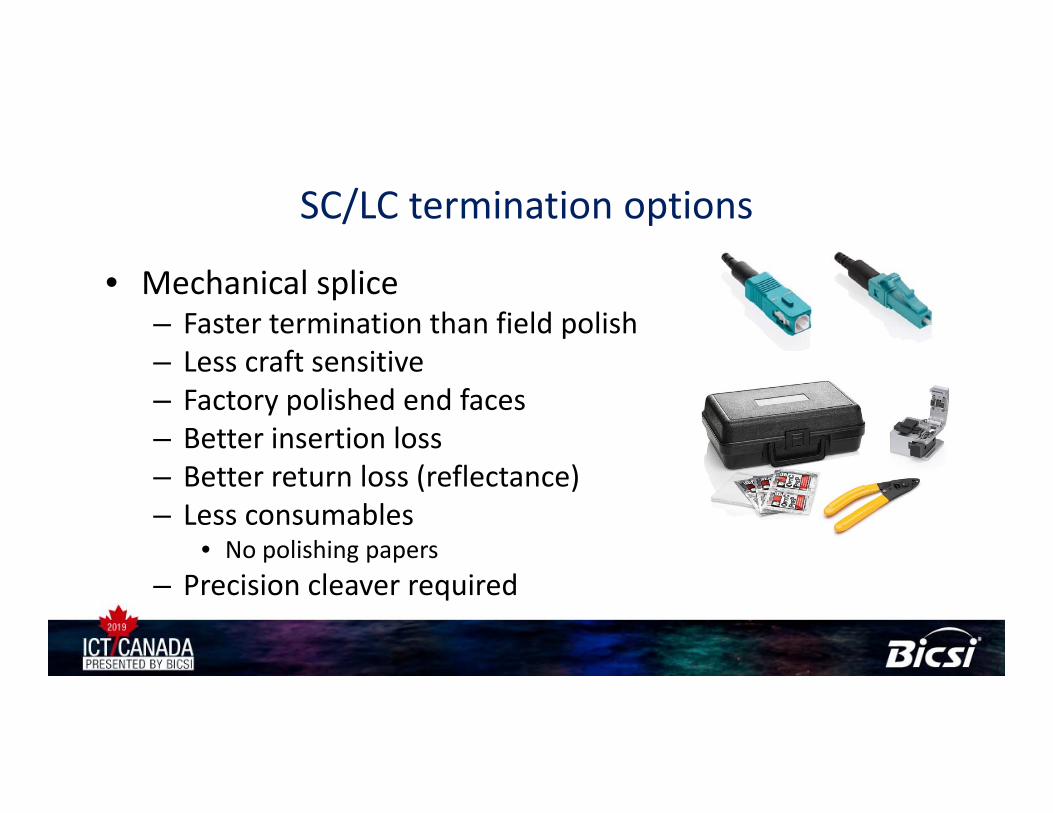
SC/LC termination options
• Mechanical splice– Faster termination than field polish– Less craft sensitive– Factory polished end faces– Better insertion loss– Better return loss (reflectance)– Less consumables
• No polishing papers– Precision cleaver required
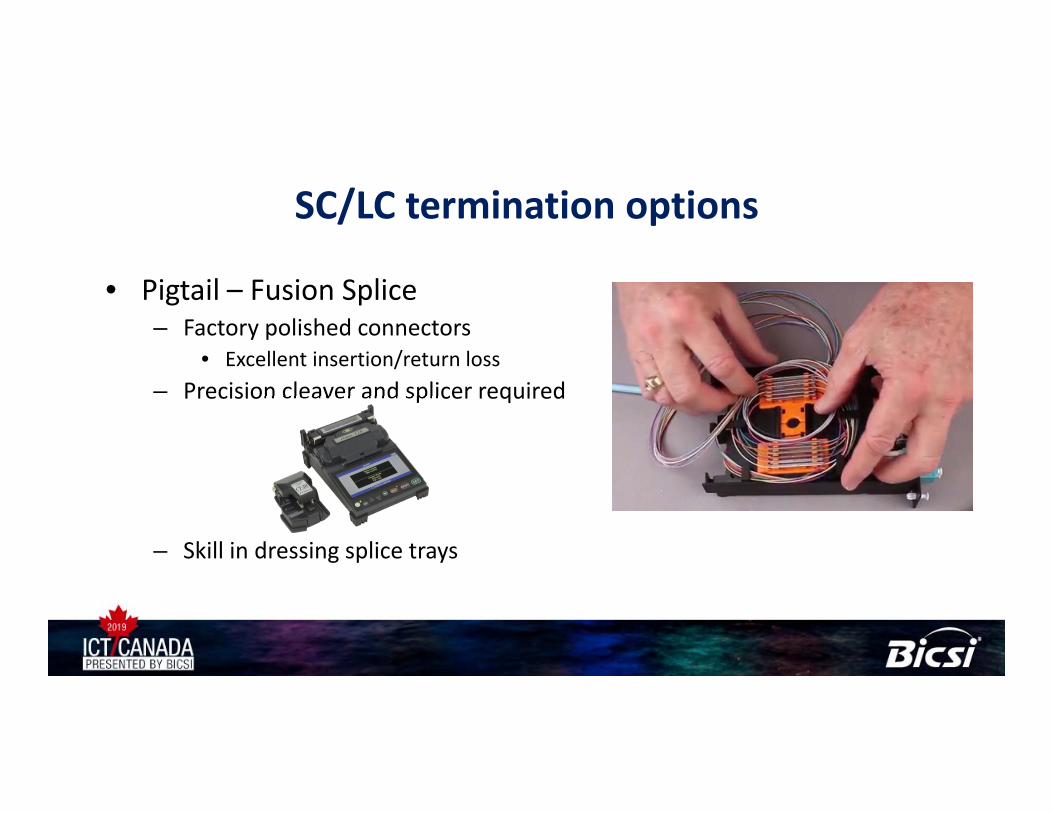
SC/LC termination options
• Pigtail – Fusion Splice– Factory polished connectors
• Excellent insertion/return loss– Precision cleaver and splicer required
– Skill in dressing splice trays
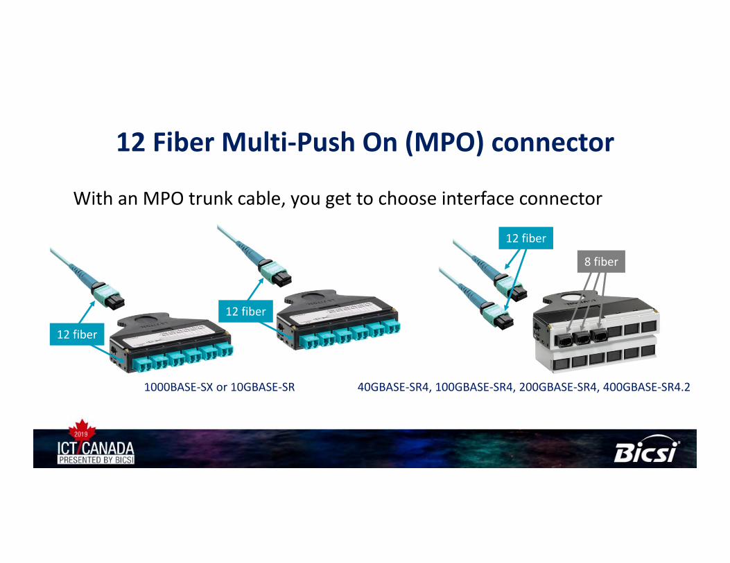
12 Fiber Multi‐Push On (MPO) connector
With an MPO trunk cable, you get to choose interface connector
1000BASE‐SX or 10GBASE‐SR
12 fiber
12 fiber
12 fiber
8 fiber
40GBASE‐SR4, 100GBASE‐SR4, 200GBASE‐SR4, 400GBASE‐SR4.2
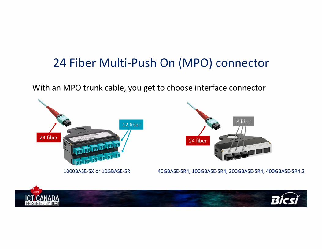
24 Fiber Multi‐Push On (MPO) connector
With an MPO trunk cable, you get to choose interface connector
1000BASE‐SX or 10GBASE‐SR 40GBASE‐SR4, 100GBASE‐SR4, 200GBASE‐SR4, 400GBASE‐SR4.2
24 fiber
12 fiber
24 fiber
8 fiber
Takeaways• Keep links under 100 m (328 ft.) for new OM4 multimode installs• Proprietary technologies to reuse existing duplex links now available• OM5 offers an advantage over OM3/4 for SWDM/BiDi only• Field polished single‐mode connectors may not support ≥100 Gb/s• Concatenated single‐mode links may benefit from APC connectors• MPO trunk cables offer flexibility and performance• 24‐fiber multimode MPO cables cover you from 100 Mb/s to 400 Gb/s• Interest in single‐mode increasing due to historical length reductions

Thank You