Embed Size (px)
Citation preview
Publ. 9-AM681
DENISON HYDRAULICSJupiter 500 Driver Card
Series S20-11712-0
E-Mail: [email protected] Internet: http://www.denisonhydraulics.com

SYSTEM FEATURES
2
SYSTEM FEATURES • Controls “Goldcup” and “Worldcup” Series Piston Pumps and the F5C Flow Control Valve
• Open or Closed Loop Control (w/Options Card)
• Eurocard Format for Eurorack or Panel mounting
• Separately Adjustable Positive and Negative Ramps(.1-40 sec.)
• Adjustable Dither for F5C
• Multiple Input Commands:
• Remote Potentiometer (10K CT)
• (±5) and (±10) VDC Voltage Inputs
• (±4-20mA), (±0-20mA) and (12±8mA) Current Loop Inputs
• Differential or Single-Ended
• Auxiliary Inputs
• Front Panel Operator Controls:
• Easy Calibration
• LED Control Indicators
• Potentiometer Adjustments
• Special Field Calibration Features
• Special Safety Features
SPECIFICATIONS
3
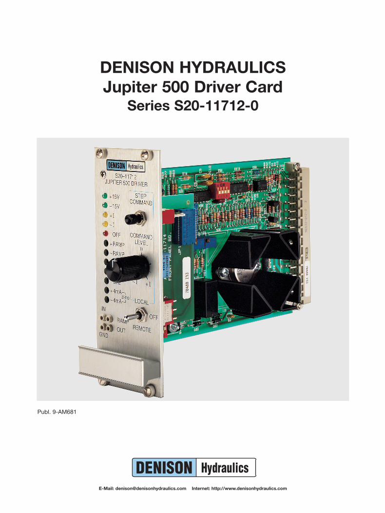
REMOTE COMMAND INPUTS Potentiometer Input: 10K, 5K ohms(Choice of one) Input Impedance: 100K ohms
Voltage Inputs (Single or Differential): ±0-5VDC, ±0-10VDC
Input Impedance(Single Ended): 100K ohms
Input Impedance(Differential): 200K ohms
Current Loop Inputs(Differential): ±4-20mA, ±0-20mA, 12±8mA
Input Impedance(4-20mA, 12±8mA): 309 ohms
Input Impedance(0-20mA): 249 ohms
Soft Stop Input: Gnd to stop
AUXILIARY REMOTE Potentiometer Input: 10K ohmsCOMMAND INPUT Input Impedance: 100K ohms(Choice of one) Voltage Input
(Single Ended): ±0-10VDCInput Impedance: 100K ohmsVoltage Input
(Single Ended): ±0-1VDCInput Impedance: 10K ohms
RAMP GENERATOR Switchable On or OffPositive Ramp Range A: 0.1-6 Sec
(Rising) Range B: 0.4-40 SecNegative Ramp Range A: 0.1-6 Sec
(Falling) Range B: 0.4-40 SecRamp at zero output: +13VDC
OUTPUT DRIVER Linear Constant Current with Current FeedbackSwitchable Unidirectional or BidirectionalSwitchable Dither On or OffCurrent Limited Short-Circuit Protected
Current Gain Adjustment: ±100-350mAZero Current Adjustment
(@ Min Gain): ±0-20mAStroker Coil Operating Characteristics
(25 ohm Coil) Output current(Bidirectional)* ±0-350mA
Voltage Compliance(Jupiter Supply): ±0-15VDC
Voltage Compliance(±15VDC Supply): ±0-11VDC
*May be switched to Unidirectional Operation for Worldcup Pumps.
F5C Operating Characteristics (60 ohm Coil)(See Note 1)
Output Current(Unidirectional) 0-220mA
Voltage Compliance(Jupiter Supply): 0-17VDC
Dither Amplitude(% of Current Output): 0-10%
Dither Frequency: 10-100HZ
SPECIFICATIONS
4
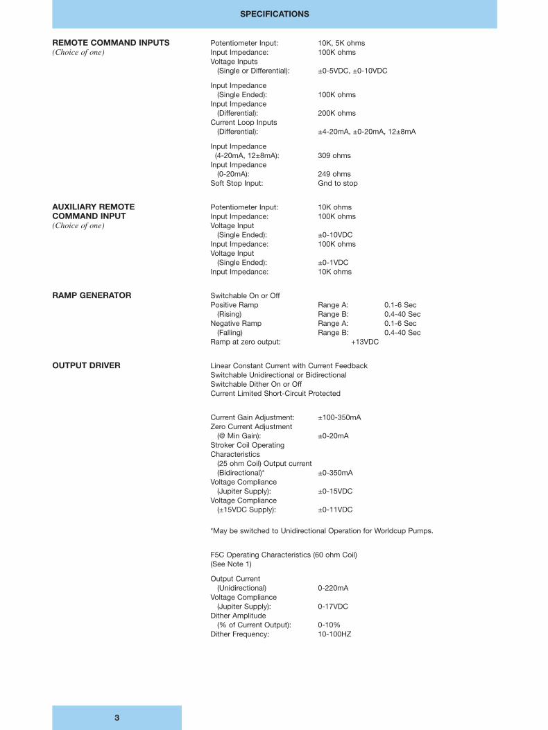
Maximum Output Ratings Short-Circuit Current
(Positive): +370mA Short-Circuit Current
(Negative): -410mA Open-Circuit Voltage
(Jupiter Supply): ±28VDCOpen-Circuit Voltage
(±5VDC Only): ±14VDC
ANALOG FEEDBACK INPUTS Horsepower Limit: ±10VDCMajor Loop: ±10VDCMinor Loop w/Balance
Adjustment: ±2.5-15VDCInput Command Disable: Gnd to Disable
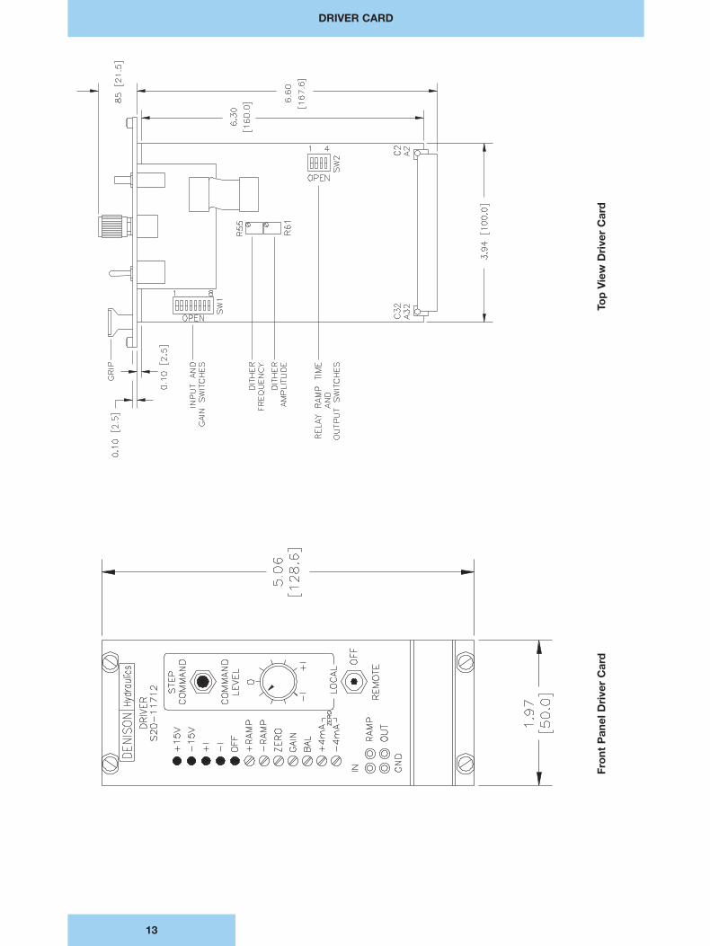
FRONT PANEL LED INDICATORS +15VDC +15VDC Power Supply Operational-15VDC -15VDC Power Supply Operational+I Positive Output Current to Coil-l Negative Output Current to Coil Off Open Circuit to Coil, Output Current I Off,
Emergency Shutdown Relay K1 De-Energized
FRONT PANEL +Ramp Adjusts Positive Ramp TimePOTENTIOMETER -Ramp Adjusts Negative Ramp TimeADJUSTMENTS Zero Adjusts Zero Scale Output Current I for Zero Input
Gain Adjusts Full Scale Output Current I for Max InputBal Balances the Input Command with the Minor Loop
Feedback+4mA Zero Adjusts Zero Output Current I for +4mA Current Input
Also Adjusts Zero Output for +12mA (12±8mA Loop)-4mA Zero Adjusts Zero Output Current I for -4mA Current Input
FRONT PANEL Local-Off-Remote Switch selects the mode of operation for the Driver Card. RemoteLOCAL CONTROLS selects Remote Operations and Local selects Front Panel Operation. Off de-energizes (See Note 2) the shutdown relay to open the circuit to the coil.
Command Level Potentiometer adjusts the input command from maximum input in one direction thru zero to maximum input in the opposite direction in Local Mode.If zero and gain of the output stage are adjusted for full scale output current, this pot can swing the output from positive full scale to negative full scale, which for apump means swinging the pump from full stroke in one direction to full stroke in the opposite direction. Only the positive side of the pot is functional if unidirectionaloutput is selected.
Step Command Pushbutton triggers ramping of the output from zero current to the±current level set by the command level pot, permitting direct measurement andadjustment of ramp times.
FRONT PANEL TEST POINTS In Input Command (±10VDC)Ramp Ramp Output (±10VDC)Out Coil Current Scaled ±1mV per ±1mV per ±1mAGND Signal Ground Reference
EMERGENCY SHUTDOWN The normally-open contact of shutdown relay K1 is placed in series between theoutput power transistor and the coil to provide an open circuit backup in the event of an emergency. The shutdown input is grounded to energize the coil for normaloperation and opened to de-energize the coil for emergency shutdown. This relay is normally operated externally, but may be overridden locally by placing the Local-Off-Remote switch in the Off position.
Coil Energized(40mA sinking): 0 VDC (Gnd)
Coil De-Energized: 15 VDC (or Open) Remote Shutdown Option: +12-24 VDC
SPECIFICATIONS
5
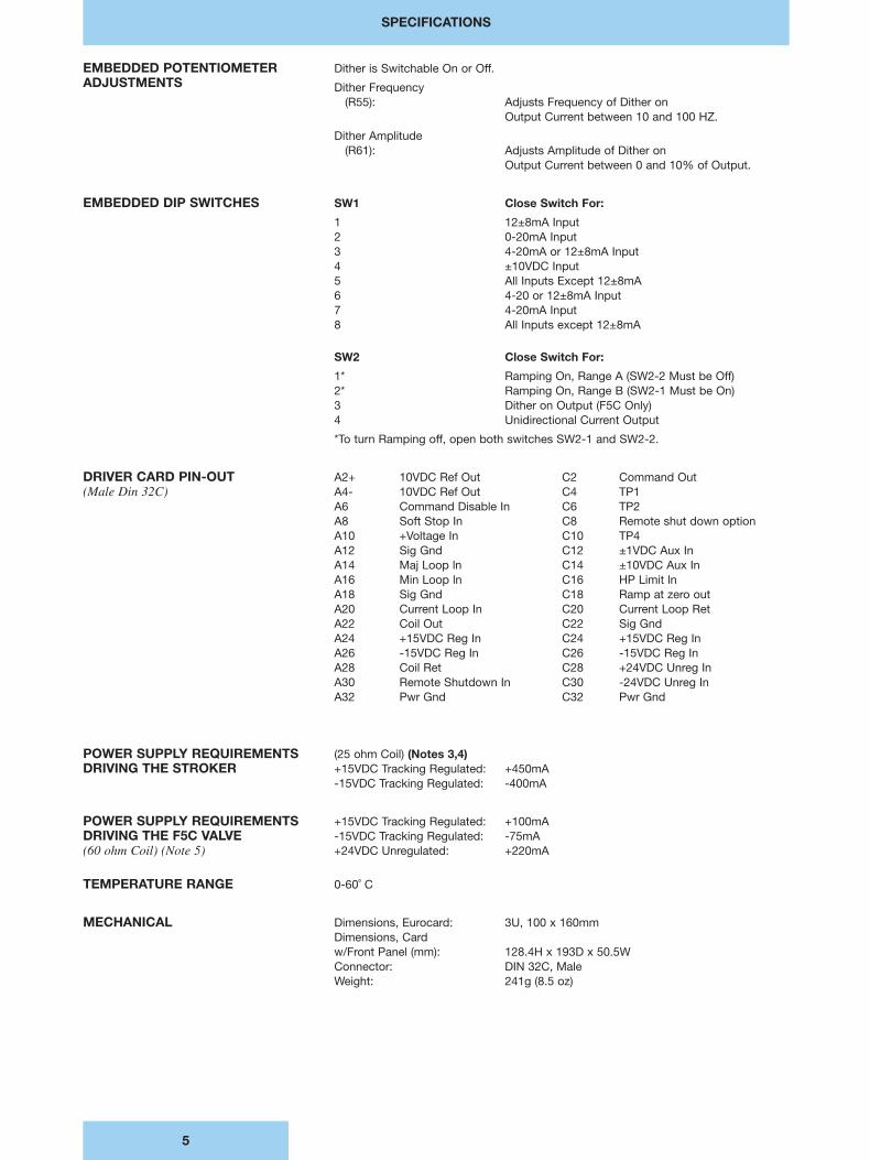
EMBEDDED POTENTIOMETER Dither is Switchable On or Off.ADJUSTMENTS Dither Frequency
(R55): Adjusts Frequency of Dither onOutput Current between 10 and 100 HZ.
Dither Amplitude(R61): Adjusts Amplitude of Dither on
Output Current between 0 and 10% of Output.
EMBEDDED DIP SWITCHES SW1 Close Switch For:
1 12±8mA Input2 0-20mA Input3 4-20mA or 12±8mA Input4 ±10VDC Input5 All Inputs Except 12±8mA6 4-20 or 12±8mA Input7 4-20mA Input8 All Inputs except 12±8mA
SW2 Close Switch For:
1* Ramping On, Range A (SW2-2 Must be Off)2* Ramping On, Range B (SW2-1 Must be On)3 Dither on Output (F5C Only)4 Unidirectional Current Output
*To turn Ramping off, open both switches SW2-1 and SW2-2.
DRIVER CARD PIN-OUT A2+ 10VDC Ref Out C2 Command Out(Male Din 32C) A4- 10VDC Ref Out C4 TP1
A6 Command Disable In C6 TP2A8 Soft Stop In C8 Remote shut down optionA10 +Voltage In C10 TP4A12 Sig Gnd C12 ±1VDC Aux InA14 Maj Loop ln C14 ±10VDC Aux InA16 Min Loop ln C16 HP Limit lnA18 Sig Gnd C18 Ramp at zero outA20 Current Loop In C20 Current Loop RetA22 Coil Out C22 Sig GndA24 +15VDC Reg In C24 +15VDC Reg InA26 -15VDC Reg In C26 -15VDC Reg InA28 Coil Ret C28 +24VDC Unreg InA30 Remote Shutdown In C30 -24VDC Unreg InA32 Pwr Gnd C32 Pwr Gnd
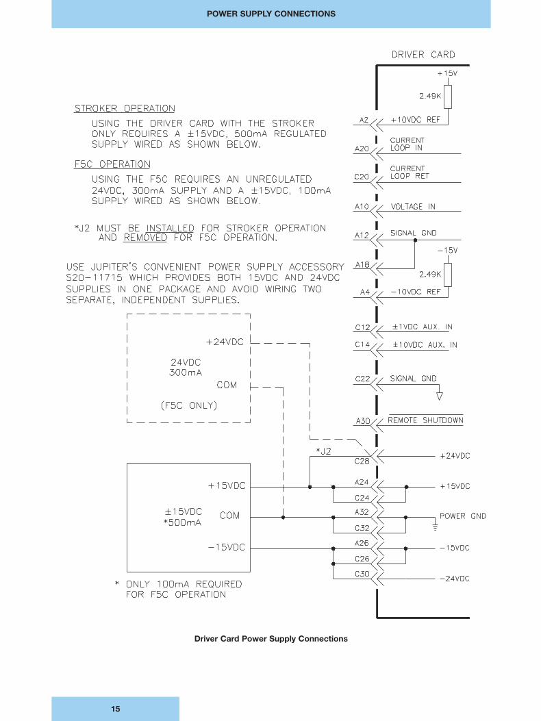
POWER SUPPLY REQUIREMENTS (25 ohm Coil) (Notes 3,4)DRIVING THE STROKER +15VDC Tracking Regulated: +450mA
-15VDC Tracking Regulated: -400mA
POWER SUPPLY REQUIREMENTS +15VDC Tracking Regulated: +100mADRIVING THE F5C VALVE -15VDC Tracking Regulated: -75mA(60 ohm Coil) (Note 5) +24VDC Unregulated: +220mA
TEMPERATURE RANGE 0-60˚ C
MECHANICAL Dimensions, Eurocard: 3U, 100 x 160mmDimensions, Card w/Front Panel (mm): 128.4H x 193D x 50.5WConnector: DIN 32C, MaleWeight: 241g (8.5 oz)
SPECIFICATIONS
6
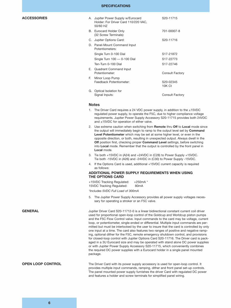
ACCESSORIES A. Jupiter Power Supply w/Eurocard S20-11715Holder: For Driver Card 110/220 VAC,50/60 HZ
B. Eurocard Holder Only 701-00007-8(32 Screw Terminals):
C. Jupiter Options Card: S20-11716
D. Panel-Mount Command InputPotentiometers:
Single Turn 0-100 Dial S17-21872
Single Turn 100 — 0-100 Dial S17-22773
Ten-Turn 0-100 Dial S17-22746
E. Quadrant Command Input Potentiometer: Consult Factory
F. Minor Loop PumpFeedback Potentiometer: S20-02345
10K Ct
G. Optical Isolation forSignal Inputs: Consult Factory
Notes1. The Driver Card requires a 24 VDC power supply, in addition to the ±15VDC
regulated power supply, to operate the F5C, due to higher compliance voltagerequirements. Jupiter Power Supply Accessory S20-11715 provides both 24VDCand ±15VDC for operation of either valve.
2. Use extreme caution when switching from Remote thru Off to Local mode sincethe output will immediately begin to ramp to the output level set by CommandLevel Potentiometer which may be set at some higher level, or even in theopposite direction, or both, resulting in unexpected output. Always dwell in theOff position first, checking proper Command Level settings, before switching into Local mode. Remember that the output is controlled by the front panel inLocal mode.
3. Tie both +15VDC in (A24) and +24VDC in (C28) to Power Supply +15VDC. Tie both -15VDC in (A26) and -24VDC in (C30) to Power Supply -15VDC.
4. If the Options Card is used, additional +15VDC current capacity is required as follows:
ADDITIONAL POWER SUPPLY REQUIREMENTS WHEN USING THE OPTIONS CARD+15VDC Tracking Regulated: +250mA *15VDC Tracking Regulated: 80mA
*Includes 5VDC Full Load of 300mA
5. The Jupiter Power Supply Accessory provides all power supply voltages neces-sary for operating a stroker or an F5C valve.
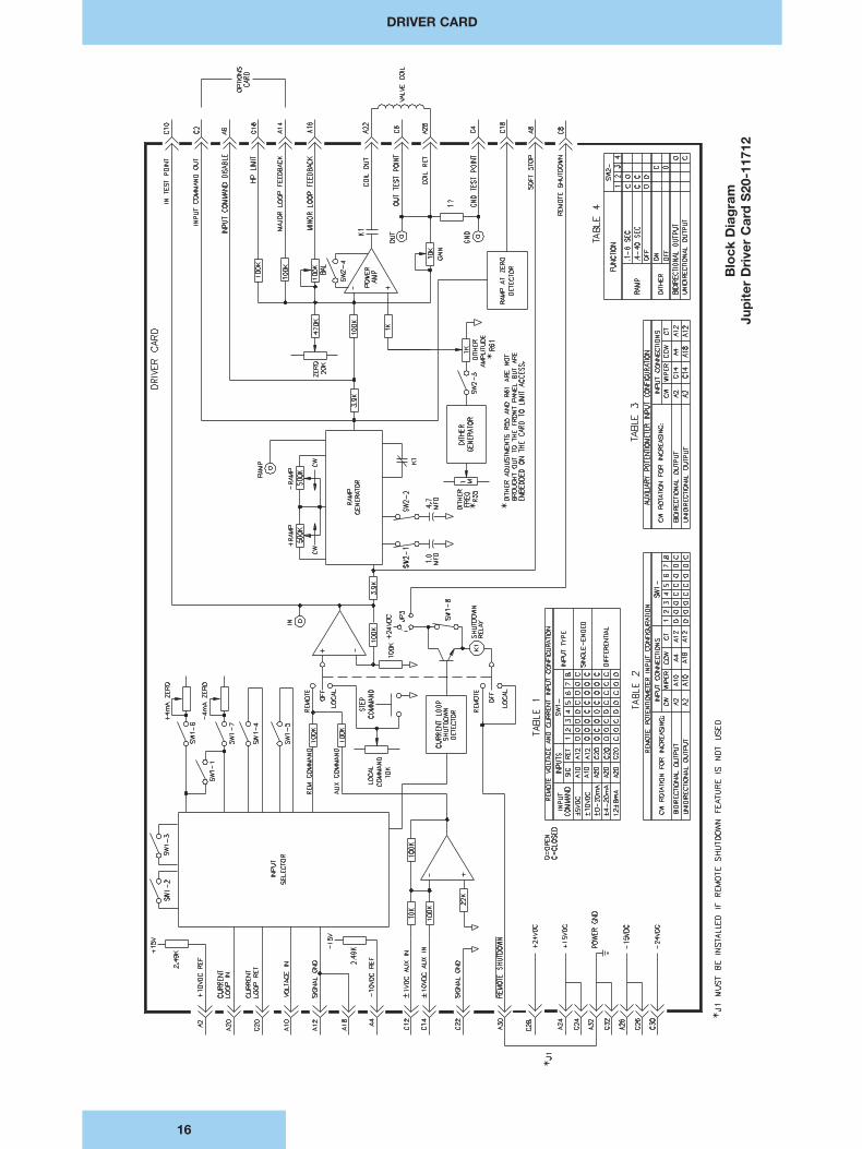
GENERAL Jupiter Driver Card S20-11712-0 is a linear bidirectional constant current coil driverused for proportional open-loop control of the Goldcup and Worldcup piston pumpsand the F5C Flow Control valve. Input commands to the card may be voltage, currentloop, or potentiometer, single-ended or differential. Multiple input commands are per-mitted but must be interlocked by the user to insure that the card is controlled by onlyone input at a time. The card also features two ranges of positive and negative ramp-ing, optional dither for the F5C, remote emergency shutdown control, and provisionsfor closed-loop control with Jupiter Options Card S20-11716. The Driver card is pack-aged in a 3U Eurocard size and may be operated with stand alone DC power suppliesor with Jupiter Power Supply Accessory S20-11715, which conveniently combines the required DC power supplies with a Eurocard holder in a single panel mountedpackage.
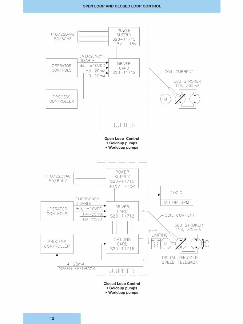
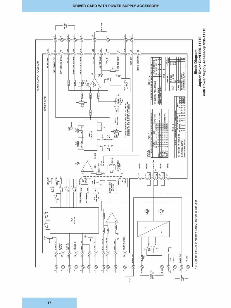
OPEN LOOP CONTROL The Driver Card with its power supply accessory is used for open-loop control. Itprovides multiple input commands, ramping, dither and front panel set-up controls.The panel mounted power supply furnishes the driver Card with regulated DC powerand features a holder and screw terminals for simplified panel wiring.
GENERAL
7
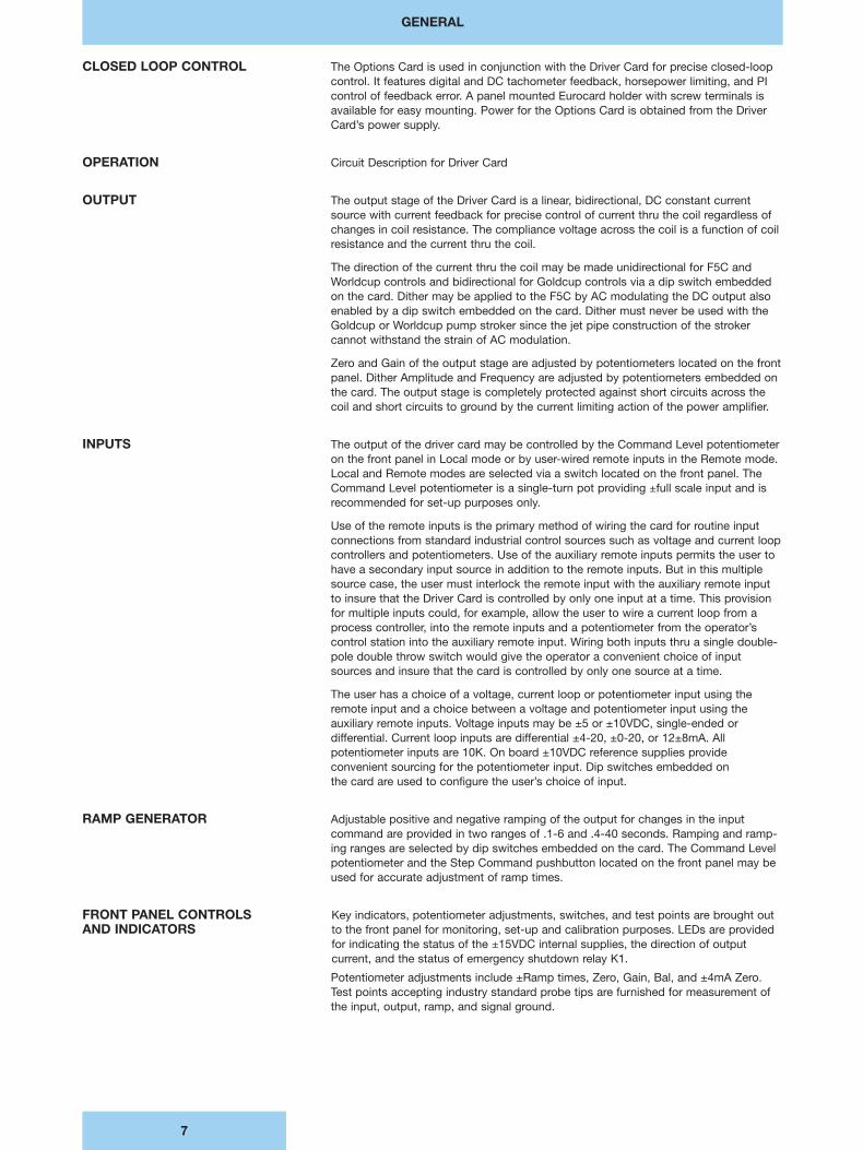
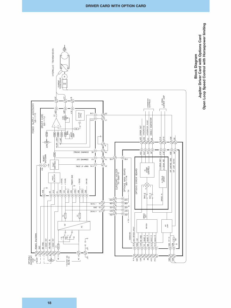
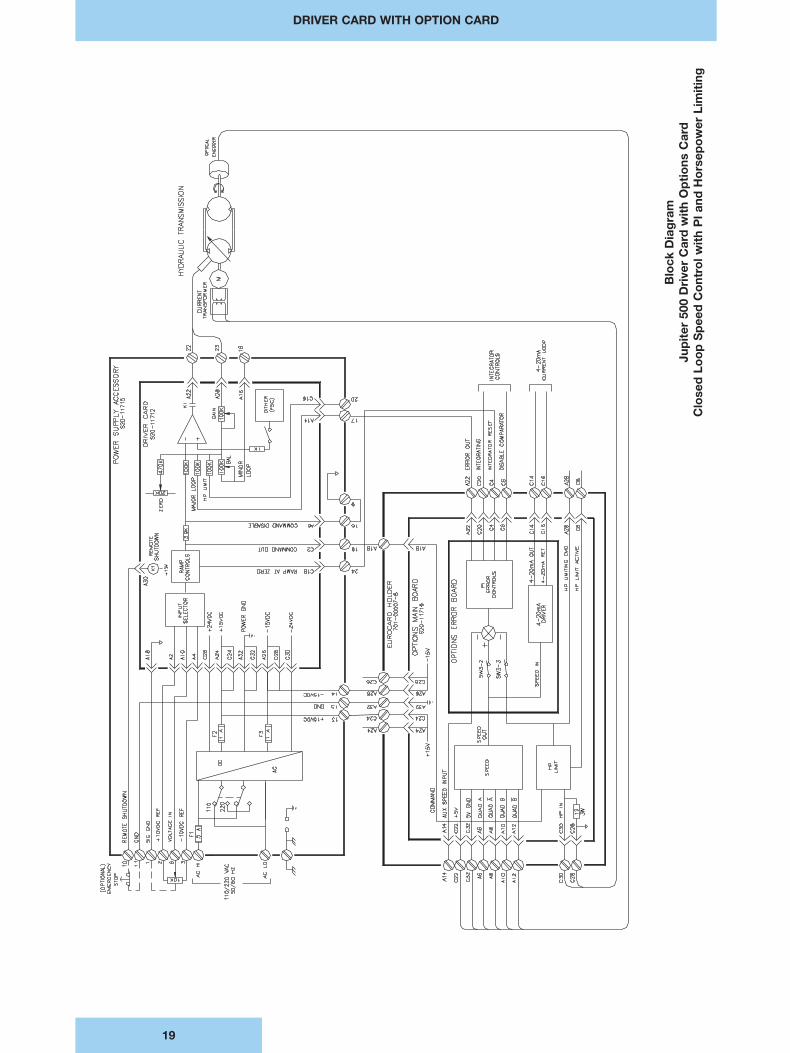
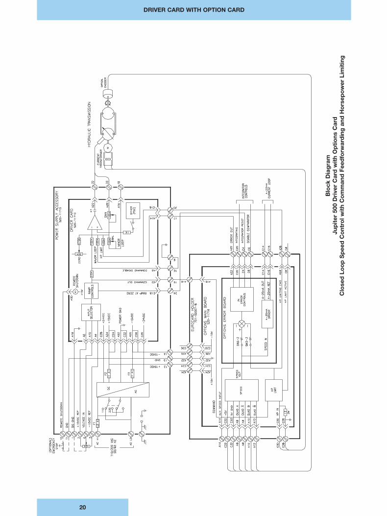
CLOSED LOOP CONTROL The Options Card is used in conjunction with the Driver Card for precise closed-loopcontrol. It features digital and DC tachometer feedback, horsepower limiting, and PIcontrol of feedback error. A panel mounted Eurocard holder with screw terminals isavailable for easy mounting. Power for the Options Card is obtained from the DriverCard’s power supply.
OPERATION Circuit Description for Driver Card
OUTPUT The output stage of the Driver Card is a linear, bidirectional, DC constant currentsource with current feedback for precise control of current thru the coil regardless ofchanges in coil resistance. The compliance voltage across the coil is a function of coilresistance and the current thru the coil.
The direction of the current thru the coil may be made unidirectional for F5C andWorldcup controls and bidirectional for Goldcup controls via a dip switch embeddedon the card. Dither may be applied to the F5C by AC modulating the DC output alsoenabled by a dip switch embedded on the card. Dither must never be used with theGoldcup or Worldcup pump stroker since the jet pipe construction of the strokercannot withstand the strain of AC modulation.
Zero and Gain of the output stage are adjusted by potentiometers located on the frontpanel. Dither Amplitude and Frequency are adjusted by potentiometers embedded onthe card. The output stage is completely protected against short circuits across thecoil and short circuits to ground by the current limiting action of the power amplifier.
INPUTS The output of the driver card may be controlled by the Command Level potentiometeron the front panel in Local mode or by user-wired remote inputs in the Remote mode.Local and Remote modes are selected via a switch located on the front panel. TheCommand Level potentiometer is a single-turn pot providing ±full scale input and isrecommended for set-up purposes only.
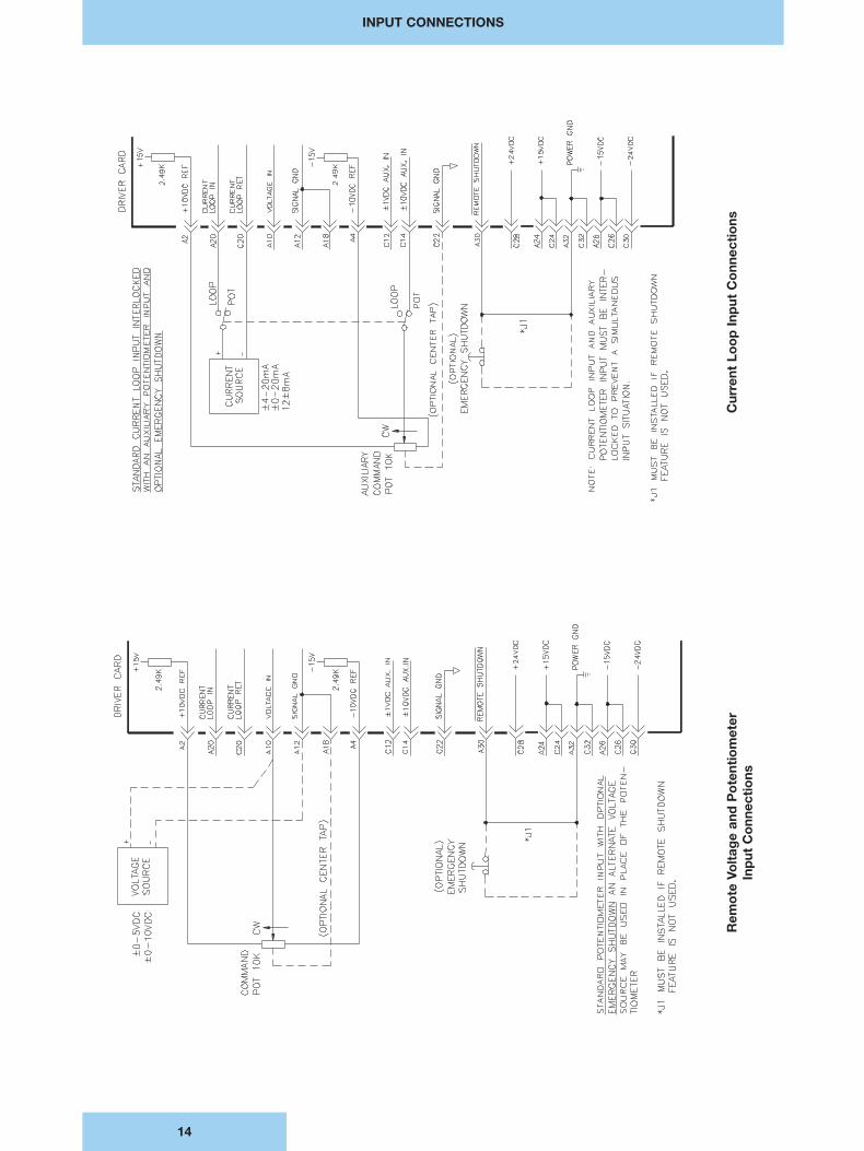
Use of the remote inputs is the primary method of wiring the card for routine inputconnections from standard industrial control sources such as voltage and current loopcontrollers and potentiometers. Use of the auxiliary remote inputs permits the user tohave a secondary input source in addition to the remote inputs. But in this multiplesource case, the user must interlock the remote input with the auxiliary remote inputto insure that the Driver Card is controlled by only one input at a time. This provisionfor multiple inputs could, for example, allow the user to wire a current loop from aprocess controller, into the remote inputs and a potentiometer from the operator’scontrol station into the auxiliary remote input. Wiring both inputs thru a single double-pole double throw switch would give the operator a convenient choice of inputsources and insure that the card is controlled by only one source at a time.
The user has a choice of a voltage, current loop or potentiometer input using theremote input and a choice between a voltage and potentiometer input using theauxiliary remote inputs. Voltage inputs may be ±5 or ±10VDC, single-ended ordifferential. Current loop inputs are differential ±4-20, ±0-20, or 12±8mA. Allpotentiometer inputs are 10K. On board ±10VDC reference supplies provide convenient sourcing for the potentiometer input. Dip switches embedded on the card are used to configure the user’s choice of input.
RAMP GENERATOR Adjustable positive and negative ramping of the output for changes in the inputcommand are provided in two ranges of .1-6 and .4-40 seconds. Ramping and ramp-ing ranges are selected by dip switches embedded on the card. The Command Levelpotentiometer and the Step Command pushbutton located on the front panel may beused for accurate adjustment of ramp times.
FRONT PANEL CONTROLS Key indicators, potentiometer adjustments, switches, and test points are brought outAND INDICATORS to the front panel for monitoring, set-up and calibration purposes. LEDs are provided
for indicating the status of the ±15VDC internal supplies, the direction of output current, and the status of emergency shutdown relay K1.
Potentiometer adjustments include ±Ramp times, Zero, Gain, Bal, and ±4mA Zero.Test points accepting industry standard probe tips are furnished for measurement ofthe input, output, ramp, and signal ground.
GENERAL
8
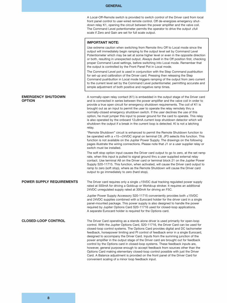
A Local-Off-Remote switch is provided to switch control of the Driver card from localfront panel control to user-wired remote control. Off de-energizes emergency shut-down relay K1, opening the circuit between the power amplifier and the valve coil. The Command Level potentiometer permits the operator to drive the output ±full scale if Zero and Gain are set for full scale output.
IMPORTANT NOTE:Use extreme caution when switching from Remote thru Off to Local mode since theoutput will immediately begin ramping to the output level set by Command LevelPotentiometer which may be set at some higher level or even in the opposite directionor both, resulting in unexpected output. Always dwell in the Off position first, checkingproper Command Level settings, before switching into Local mode. Remember thatthe output is controlled by the Front Panel Pot in Local mode.
The Command Level pot is used in conjunction with the Step Command pushbuttonfor set-up and calibration of the Driver card. Pressing then releasing the StepCommand pushbutton in Local mode triggers ramping of the output from zero currentto the current level set by the Command Level potentiometer, permitting accurate andsimple adjustment of both positive and negative ramp times.
EMERGENCY SHUTDOWN A normally-open relay contact (K1) is embedded in the output stage of the Driver cardOPTION and is connected in series between the power amplifier and the valve coil in order to
provide a true open circuit for emergency shutdown requirements. The coil of K1 isbrought out as an input to permit the user to operate the relay remotely thru anormally-closed emergency shutdown switch. If the user declines the use of thisoption, he must jumper this input to power ground for the card to operate. This relayis also operated by the onboard 12±8mA current loop shutdown detector which willshutdown the output if a break in the current loop is detected. Kl is not a latchingrelay.
“Remote Shutdown” circuit is enhanced to permit the Remote Shutdown function tobe operated with a +15-+24VDC signal on terminal C8. JP3 selects this function. Thisfunction is not available on the Jupiter Power Supply. The drawings on the followingpages illustrate the wiring connections. Please note that J1 or a user supplier relay orswitch must be installed.
The soft stop option input causes the Driver card output to go to zero, at the set ramprate, when this input is pulled to signal ground thru a user supplied external relaycontact. Use terminal A8 on the Driver card or terminal block 21 on the Jupiter PowerSupply S20-11715. This function, when activated, will cause the Driver card output toramp to zero (soft stop), where as the Remote Shutdown will cause the Driver cardoutput to go immediately to zero (hard stop).
POWER SUPPLY REQUIREMENTS The Driver card requires only a single ±15VDC dual tracking regulated power supplyrated at 500mA for driving a Goldcup or Worldcup stroker. It requires an additional24VDC unregulated supply rated at 300mA for driving an F5C.
Jupiter Power Supply Accessory S20-11715 conveniently provides both ±15VDC and 24VDC supplies combined with a Eurocard holder for the driver card in a singlepanel-mounted package. This power supply is also designed to handle the powerrequired by Jupiter Options Card S20-11716 used for closed-loop applications. A separate Eurocard holder is required for the Options card.
CLOSED-LOOP CONTROL The Driver Card operating as a stands alone driver is used primarily for open-loopcontrol. With the Jupiter Options Card, S20-11716, the Driver Card can be used forclosed-loop control systems. The Options Card provides digital and DC tachometerfeedback, horsepower limiting and PI control of feedback error in a single Eurocard,designed to accompany the Driver Card. Inputs from the summing junction of thepower amplifier in the output stage of the Driver card are brought out for feedbackcontrol by the Options card in closed-loop systems. These feedback inputs are,however, general purpose enough to accept feedback from sources other than theOptions Card making elementary closed-loop control possible with just the DriverCard. A Balance adjustment is provided on the front panel of the Driver Card forconvenient scaling of a minor loop feedback input.
GENERAL
9
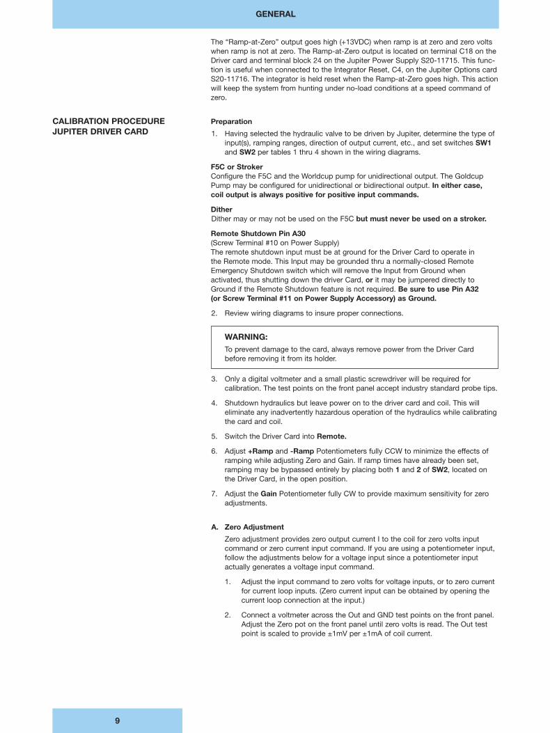
The “Ramp-at-Zero” output goes high (+13VDC) when ramp is at zero and zero voltswhen ramp is not at zero. The Ramp-at-Zero output is located on terminal C18 on theDriver card and terminal block 24 on the Jupiter Power Supply S20-11715. This func-tion is useful when connected to the Integrator Reset, C4, on the Jupiter Options cardS20-11716. The integrator is held reset when the Ramp-at-Zero goes high. This actionwill keep the system from hunting under no-load conditions at a speed command ofzero.
CALIBRATION PROCEDURE PreparationJUPITER DRIVER CARD 1. Having selected the hydraulic valve to be driven by Jupiter, determine the type of
input(s), ramping ranges, direction of output current, etc., and set switches SW1and SW2 per tables 1 thru 4 shown in the wiring diagrams.
F5C or StrokerConfigure the F5C and the Worldcup pump for unidirectional output. The GoldcupPump may be configured for unidirectional or bidirectional output. In either case, coil output is always positive for positive input commands.
DitherDither may or may not be used on the F5C but must never be used on a stroker.
Remote Shutdown Pin A30(Screw Terminal #10 on Power Supply)The remote shutdown input must be at ground for the Driver Card to operate in the Remote mode. This Input may be grounded thru a normally-closed RemoteEmergency Shutdown switch which will remove the Input from Ground whenactivated, thus shutting down the driver Card, or it may be jumpered directly toGround if the Remote Shutdown feature is not required. Be sure to use Pin A32 (or Screw Terminal #11 on Power Supply Accessory) as Ground.
2. Review wiring diagrams to insure proper connections.
WARNING:To prevent damage to the card, always remove power from the Driver Card before removing it from its holder.
3. Only a digital voltmeter and a small plastic screwdriver will be required forcalibration. The test points on the front panel accept industry standard probe tips.
4. Shutdown hydraulics but leave power on to the driver card and coil. This willeliminate any inadvertently hazardous operation of the hydraulics while calibratingthe card and coil.
5. Switch the Driver Card into Remote.
6. Adjust +Ramp and -Ramp Potentiometers fully CCW to minimize the effects oframping while adjusting Zero and Gain. If ramp times have already been set,ramping may be bypassed entirely by placing both 1 and 2 of SW2, located onthe Driver Card, in the open position.
7. Adjust the Gain Potentiometer fully CW to provide maximum sensitivity for zeroadjustments.
A. Zero Adjustment
Zero adjustment provides zero output current I to the coil for zero volts input command or zero current input command. If you are using a potentiometer input, follow the adjustments below for a voltage input since a potentiometer input actually generates a voltage input command.
1. Adjust the input command to zero volts for voltage inputs, or to zero currentfor current loop inputs. (Zero current input can be obtained by opening thecurrent loop connection at the input.)
2. Connect a voltmeter across the Out and GND test points on the front panel.Adjust the Zero pot on the front panel until zero volts is read. The Out testpoint is scaled to provide ±1mV per ±1mA of coil current.
GENERAL
10
B. ±4mA Zero Adjustments(±4-20mA current loop input command only)
±4mA zero adjustments provide zero output current I to the coil for inputcommands between +4mA and -4mA inclusive.
1. Perform Zero Adjustment, Part A before proceeding.
2. Adjust both +4mA and -4mA pots fully CW.
3. Set the input command to +4mA.
4. With the voltmeter connected across the Out and Gnd test points on thefront panel, adjust the +4mA pot slowly CCW just until zero volts is readand stop. Do not adjust the pot beyond this point. The Out test point isscaled to provide ±1mV per ±1mA of coil current.
5. Set the input command to -4mA.
6. With the voltmeter connected across the Out and Gnd test points on thefront panel, adjust the -4mA pot slowly CCW just until zero volts is read andstop. Do not adjust the pot beyond this point. The Out test point is scaledto provide ±1mV per ±1mA of coil current.
C. 12±8mA Zero Adjustments(12±8mA current loop input command only)
12±8mA zero adjustments provide zero output current I to the coil for +12mAinput. (+Full Scale = 20mA and -Full Scale = 4mA)
1. Perform Zero Adjustment, Part A before proceeding.
2. Set the input command to +12mA.
3. With the voltmeter connected across the Out and Gnd test points on thefront panel, adjust the +4mA pot on the front panel until zero volts is read.The Out test point is scaled to provide ±1mV per ±1mA of coil current.
WARNING:Negative full scale output is produced for a 12±8mA current loop input of +4mA. A broken current loop connection (0 mA Input) will drive the output even more negative than full scale, resulting in an unintentional and possibly hazardoushydraulic-mechanical situation. Remember to Place Switch SW1-8 in the OpenPosition to enable the automatic current loop shutdown detector which trips shutdown relay K1 if an open-circuit is detected in the loop.
D. Gain AdjustmentGain Adjustment provides full scale output current I thru the coil for maximuminput command.
1. Reconnect input and adjust the input command to + or - Full Scale. Fullscale Voltage Inputs may be ±5V, ±10V, or a potentiometer rotated fully CW or CCW. Full scale Current loop inputs may be ±20mA for ±0-20mA and ±4-20mA loops, and +20 and +4mA for the 12±8mA loop.
2. Adjust the Gain pot to provide Full Stroke at the Pump or Full Flow thruthe F5C. The output current from the driver card required to produce FullStroke or Full Flow may be read across the Out and Gnd test points scaledto provide ±1mV per ±1mA of coil current.
E. Ramp Adjustments
A Ramp Adjustment sets the time it takes for the output current to change inresponse to a step change in the input. The output current may ramp up or rampdown to the changed output commanded by the input depending upon the direc-tion the input changes. The +Ramp Pot adjusts ramp-up time and the -RampPot adjusts the ramp-down time.
1. Shutdown hydraulics but leave power on to the Driver Card.
2. Switch the Driver Card into Local mode.
GENERAL
11
WARNING: Remember that the Driver Card responds to the local command pot in the Local Modeand will drive the coil as commanded. Shutting down the hydraulics during this set-upoperation will prevent any inadvertently hazardous operation of the load.
3. To adjust Positive Ramp Time, connect a voltmeter across the Ramp andGnd test points on the front panel, adjust the Local Command pot fully CWto +I, press Step Command and hold until zero volts is read, then release.Ramp voltage will begin ramping from zero to 10VDC full scale. Ramp time is the time it takes to ramp from zero to 10VDC and may be measured by asimple wrist watch. Ramp time is adjustable between .1 and 6 sec. orbetween .4 and 40 sec. depending upon the ramp range selected on theDriver Card. (See SW2). Adjust the +Ramp pot on the front panel CW toIncrease Ramp Time and CCW to Decrease Ramp Time.
4. To adjust Negative Ramp Time, connect a voltmeter across the Ramp andGnd test points on the front panel, adjust the Local Command pot fullyCCW to -I, press Step Command and hold until zero volts is read, thenrelease. Ramp voltage will begin ramping from zero to -10VDC full scale.Ramp time is the time it takes to ramp from zero to -10VDC and may bemeasured by a simple wrist watch. Ramp time is adjustable between .1 and6 sec. or between .4 and 40 sec. depending upon the ramp range selectedon the Driver Card (See SW2). Adjust the +Ramp pot on the front panel CWto Increase Ramp Time and CCW to Decrease Ramp Time.
F. Balance Adjustment(Use only with Minor Closed-Loop Feedback on pin A16)
1. To begin, adjust Bal pot fully CW to provide Maximum Minor LoopFeedback.
2. Apply power to the hydraulics and set the Input Command at the desiredoperating point. With the Bal adjusted fully CW in Step 1, the system shouldnot be able to reach this operating point since maximum feedback is overrid-ing the Input Command. Turn the Bal pot slowly CCW to reduce the amountof feedback to the point where the feedback matches the Input Commandand the system moves toward the operating point.
G. Dither Adjustments(Use only with the F5C Flow Control Valve)
Dither is a sinusoidal signal superimposed upon the coil current flowing thru theF5C. It is used to reduce hysteresis in the valve, thus making the control of theflow thru the valve more responsive to the Input Command. Dither is adjusted byvarying the frequency and amplitude of the sinusoidal signal.
Potentiometer adjustments for Dither Frequency and Amplitude are embeddedon the Driver Card and labeled R55 and R61 respectively. Dither may beentirely disabled by placing SW2-3 in the Open position.
WARNING:
Never use Dither with a Pump Stroker. Always disable Dither by placing SW2-3 in the Open position.
1. Dither adjustments are made with power applied to the hydraulics and thesystem operational.
2. Place SW2-3 in the Closed position to enable Dither.
3. To begin, adjust Dither Frequency pot R55 fully CCW for minimumfrequency and the Amplitude Pot R61 fully CW for maximum amplitude.
4. Apply power to the hydraulics and observe valve pulsating and humming to the dither set at maximum amplitude and minimum frequency.
5. Decrease the amplitude (R61 CCW) and increase the frequency (R55 CW)until an optimum point is reached where pulsating and humming of the valve body has ceased, yet the spool is still felt to be moving and flowcontrol responds to the input command in both directions indicating reduced hysteresis.
OPEN LOOP AND CLOSED LOOP CONTROL
12
Open Loop Control• Goldcup pumps• Worldcup pumps
Closed Loop Control• Goldcup pumps• Worldcup pumps
DRIVER CARD
13
Top
Vie
w D
rive
r C
ard
Fro
nt P
anel
Dri
ver
Car
d
INPUT CONNECTIONS
14
Cur
rent
Lo
op
Inp
ut C
onn
ecti
ons
Rem
ote
Vo
ltag
e an
d P
ote
ntio
met
er
Inp
ut C
onn
ecti
ons
POWER SUPPLY CONNECTIONS
15
Driver Card Power Supply Connections
DRIVER CARD
16
Blo
ck D
iag
ram
Jup
iter
Dri
ver
Car
d S
20-1
1712
DRIVER CARD WITH POWER SUPPLY ACCESSORY
17
Blo
ck D
iag
ram
Jup
iter
Dri
ver
Car
d S
20-1
1712
wit
h P
ow
er S
upp
ly A
cces
sory
S20
-117
15
DRIVER CARD WITH OPTION CARD
18
Blo
ck D
iag
ram
Jup
iter
Dri
ver
Car
d w
ith
Op
tio
ns C
ard
Op
en L
oo
p S
pee
d C
ont
rol w
ith
Ho
rsep
ow
er li
mit
ing
DRIVER CARD WITH OPTION CARD
19
Blo
ck D
iag
ram
Jup
iter
500
Dri
ver
Car
d w
ith
Op
tio
ns C
ard
Clo
sed
Lo
op
Sp
eed
Co
ntro
l wit
h P
l and
Ho
rsep
ow
er L
imit
ing
DRIVER CARD WITH OPTION CARD
20
Blo
ck D
iag
ram
Jup
iter
500
Dri
ver
Car
d w
ith
Op
tio
ns C
ard
Clo
sed
Lo
op
Sp
eed
Co
ntro
l wit
h C
om
man
d F
eed
forw
ard
ing
and
Ho
rsep
ow
er L
imit
ing
DRIVER CARD WITH OPTION CARD
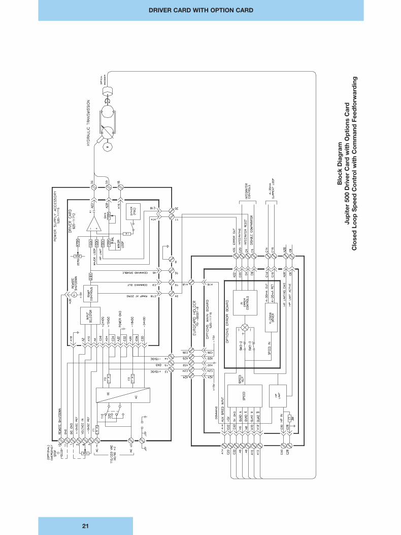
21
Blo
ck D
iag
ram
Jup
iter
500
Dri
ver
Car
d w
ith
Op
tio
ns C
ard
Clo
sed
Lo
op
Sp
eed
Co
ntro
l wit
h C
om
man
d F
eed
forw
ard
ing
DRIVER CARD WITH OPTION CARD
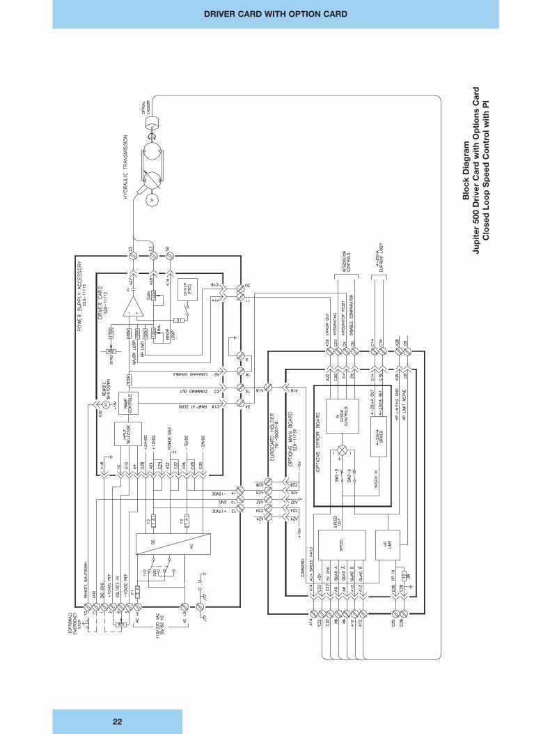
22
Blo
ck D
iag
ram
Jup
iter
500
Dri
ver
Car
d w
ith
Op
tio
ns C
ard
Clo
sed
Lo
op
Sp
eed
Co
ntro
l wit
h P
l

SALES & SERVICE WORLDWIDE
International DistributorsIn Europe:CyprusEastern EuropeThe Faroe IslandsFinlandGreeceIcelandNorwayPortugalSwitzerlandTurkey
In Africa:AlgeriaEgyptIvory CoastMoroccoNigeriaSouth AfricaTogoTunisia
In Middle East:IranIsraelLebanonPakistanQatarSaudi ArabiaSyriaUnited Arab Emirates
In Far East:IndonesiaKoreaMalaysiaNew ZealandPhilippinesThailand
AustraliaDENISON HYDRAULICS Pty. Ltd.41-43 St. Hillers RoadP.O. Box 192Auburn, N.S.W. 2144Tel. (612) 9646 5200Fax (612) 9643 1305Other sales offices:QueenslandSouth Wantirna VictoriaWestern Australia
AustriaDENISON HYDRAULIK GmbHZweigniederlassung LinzHaidbachstraße 69A-4061 PaschingTel. (43) 7229 4887Fax (43) 7229 63092
BeneluxDENISON HYDRAULICSBENELUX B. V.Pascalstraat 1003316 DordrechtHollandTel. (31) 786179 900Fax (31) 786175 755
CanadaDENISON HYDRAULICSCANADA Inc.2320 Bristol Circle, Unit 1Oakville, ON L6H 5S2Tel. (905) 829 5800Fax (905) 829 5805Other sales offices:Montreal, QCCalgary, AB
China, P.R.DENISON HYDRAULICS Ltd.3F, No. 1, Mao Jia Zhai, Bai Lian JingPudong New AreaShanghai 200126,Tel. (86) 21 5886 8991Fax (86) 21 5886 1978
DenmarkDENISON HYDRAULIKDENMARK A/SIndustrikrogen 2DK-2635 IshöjTel. (45) 4371 15 00Fax (45) 4371 15 16
FinlandDENISON HYDRAULICSP.O. Box 36FIN-08101 LohjaTel. (358) 208 33 045Fax (358) 207 33 045
FranceDENISON HYDRAULICS FRANCE SA14, route du Bois BlancBP 53918105 VierzonTel. (33) 2 48 53 01 20Fax (33) 2 48 75 02 91Other sales offices:BordeauxLyonParis
GermanyDENISON HYDRAULIK GmbHHerderstrasse 26D-40721 HildenTel. (49) 2103 940-6Fax (49) 2103 940-880Other sales offices:DresdenHanoverStuttgart
Great BritainDENISON HYDRAULICS U.K.Ltd.Kenmore RoadWakefield 41, Industrial EstateWakefield, WF20XEWest YorkshireEnglandTel. (44) 19 24 826 021Fax (44) 19 24 826 146Other sales offices:Burgess Hill
Hong Kong, N. T. DENISON HYDRAULICS Ltd.Unit 3, 25/F Wharf Cable Tower9 Hoi Shing RoadTsuen WanTel. (852) 24988381Fax (852) 24991522
ItalyDENISON HYDRAULICS S.r.l.Viale Europa 6820090 Cusago Tel. (39) 2 90 33 01Fax (39) 2 90 39 06 94
JapanDENISON JAPAN Inc.4-2-1 Tsujido-ShinmachiFujisawa 251,Tel. (81) 466 35 3257Fax (81) 466 35 2029Other sales office:Osaka
Mexico, Central America, South America and CaribbeanCountries ContactDENISON HYDRAULICS Inc.6167 NW 181 Terrace Circle NorthMiami, FL 33015, USATel. (305) 362 2246Fax (305) 362 6220
Other European, Middle Eastand African Countries ContactDENISON HYDRAULICSFRANCE SA14, route du Bois BlancBP 539 18105 Vierzon CedexFranceTel. (33) 2 48 53 01 45Fax (33) 2 48 53 01 46
SingaporeDENISON HYDRAULICS S.E.A. Pte. Ltd.No. 11 Lorong Tukang Dua2261 SingaporeTel. (65) 2687840Fax (65) 2687847
SpainDENISON HYDRAULICS, S.A.Gomis, 108023 BarcelonaTel. (34) 3418 46 87Fax (34) 3211 65 07Other sales offices:San Sebastian
SwedenDENISON HYDRAULICSSVENSKA ABSporregatan 13213 77 - MalmöTel. (46) 40 21 04 40Fax (46) 40 21 47 26Other sales offices:Spånga
Taiwan, R.O.C.DENISON HYDRAULICS Ltd.6F-10, No. 79, Sec. 2, Roosevelt RoadTaipei,Tel. (886) 2 3645101 / 3645102Fax (886) 2 3639025
USADENISON HYDRAULICS Inc.14249 Industrial ParkwayMarysville, OH 43040Tel. 937 644 3915Fax 937 642 3738For nearest Distributor:Call toll free 1 800 551 5956Other sales offices:Fulton, CAMulberry, FLMoline, ILRock Island, ILKentwood, MIPortland, ORCollierville, TNArlington, TXHouston, TX
Your local DENISON representative
Prin
ted
in U
.S.A
. 2-
98
Internet: http://www.denisonhydraulics.comE-mail: [email protected]