Embed Size (px)
Citation preview
bonded at lattice defects, dislocation lines, interior boundaries,micropores, or intermetallic phases, changing them to metalhydrides. During the recombination of atomic hydrogen an ex-cess-pressure is generated in the bulk, inducing microductileyielding and deformations, internal splits, and materials fa-tigue. Therefore, hydrogen embrittlement is the only kind ofcorrosion that causes cracks inside a component and producesbrittle forced cracking from inside outwards.
The short-lasting penetration of hydrogen into the mi-crostructure of coated components is not so destructive. Sub-critical crack growth requires the conservation of the state ofstress, due to restricted hydrogen desorption. Kinetic inhibi-tions normally exist at the surface, for example dense surfacecoatings or platings, preventing hydrogen effusion and tensionrelief. If the recombination to molecular hydrogen at the sur-face is impeded, the hydrogen loading into the components in-terior proceeds and the state of tension is conserved.
5.3 Testing susceptibility on stress corrosion cracking
Considering the possibile mechanisms of crack growth, it is un-derstandable that predictions on SCC are difficult. It is there-fore necessary to test coated components for their SCC sus-ceptibility. DIN 50922 [1] classifies constant loading testing(CLT), constant extension rate testing (CERT) and testing un-der low extension rates (LERT).
During the CLT procedure coated samples are pretensionedand immersed in corrosive electrolytes for a limited period oftime until the material fails up to a maximum of 1000 h. The SCCsusceptibility of components is scaled by their endurance. There-fore, the CLT-test characterizes the SCC behaviour of materi-als induced by construction and mounting reinforced tension.
Fabrication-caused malfunctions according to internal stressshould be investigated by the CERT method. Extending sam-ples at a constant rate, the results are correlated to the corrosiveconditions to obtain information about the cracking kinetics.
Thermal-sprayed coatings are best investigated by this proce-dure. Stress corrosion cracking, depending on cooling inducedresidual stress, is observed both at coatings and base materials.It is therefore recommended to investigate samples after metal-lographic preparation with respect to main cracks, secondarycracks and crack depth.
References
1. DIN Taschenbuch 219 (1995) Korrosion and Korrosion-schutz. Beuth, Berlin
2. ASTM G 48 (1987) ASTM Annual, sec 3, vol 03.02. Amer-ican Society for Testing and Materials, Philadelphia
3. ASTM A 262–70 (1987) ASTM Annual, sec 3, vol 03.02.American Society for Testing and Materials, Philadelphia
4. Reichel K (1991) Entwicklung der Charakterisierung vonkorrosions- und verschleißbeständigen Beschichtungen unterEinsatz des Arc-PVD-Verfahrens. VDI-Verlag
5. Pajonk G (1996) Korrosionsverhalten und Charakterisie-rung von Schichtverbunden. H-D Steffens (Hrsg) ModerneBeschichtungsverfahren. Berichtsband zum DGM-Fortbil-dungsseminar 1996 der Universität Dortmund, DeutscheGesellschaft für Materialkunde e.V., Oberursel
6. Pajonk G, Steffens H-D (1996) Galvanisches Beschichtenvon Kohlenstofffasern. Tagungsband zur INNOMATA 96,7.–9. Mai in Dresden
7. Orth H (1974) Korrosion und Korrosionsschutz. Wissen-schaftliche Verlags-GmbH, Stuttgart
8. Kaesche H (1990) Die Korrosion der Metalle, 3. Auflage.Springer, Berlin Heidelberg New York
9. Rahmel A, Schwenk W (1977) Korrosion und Korrosions-schutz von Stählen. Verlag Chemie, Weinheim New York
10.Heitz E, Henkhaus R, Rahmel A (1983) Korrosionskundeim Experiment. Verlag Chemie, Weinheim New York
11.Schatt W (1991) Einführung in die Werkstoffwissenschaft.Deutscher Verlag der Grundstoffindustrie, Leipzig
290
Fresenius J Anal Chem (1997) 358 :290–293 – © Springer-Verlag 1997
H. Krause · H. Börner · R.-H. Flagmeyer
Redistribution of zinc in MeV-implanted InP studied by SNMS and PIXE/RBS/channelling
Received: 24 June 1996 / Revised: 24 January 1997 / Accepted: 28 January 1997
Abstract Zn ions with energies of 1.2 and 2.5 MeV were im-planted into InP with the intention of producing p-conductingburied layers. In order to minimize the implantation-induced
damage a priori an elevated sample temperature of 200°C waschosen. The implanted samples were annealed using RapidThermal Annealing (RTA) at 750°C. Because often a diffusionof implanted acceptors into the bulk occurs during thermaltreatment, the Zn profiles were studied for different annealingtimes using SNMS. For annealing times greater than 40 s astrong broadening of the Zn profile was observed. For a betterunderstanding of these transport phenomena, the lattice sites oc-cupied by the Zn atoms after implantation and after annealingwere investigated. It is demonstrated that the combined use ofSNMS, PIXE/RBS/channelling, and Hall effect measurementresults in more quantitative information about the incorporationof Zn into InP. From the comparison of calculated with experi-mental PIXE channelling yields it is shown that, after implan-tation, nearly all Zn atoms occupy substitutional In sites. As aresult of RTA, the substitutional Zn fraction decreases and Znatoms appear partly on tetrahedral and partly on randomly dis-tributed interstitial sites. Differential Hall effect measurementsgave hints that the remaining substitutional Zn is completelyelectrically active.
H. Krause · R.-H. FlagmeyerAbt. Nukl. Festkörperphysik, Fak. Physik Geowiss., Univ. Leipzig, Linnéstrasse 5, D-04103 Leipzig, Germany
H. Börner (Y)Abt. Halbleiterphysik, Fak. Physik Geowiss., Univ. Leipzig, Linnéstrasse 5, D-04103 Leipzig, Germany
Introduction
Generally, ion implantation is followed by an annealing treat-ment which serves to reduce the lattice damage and forces thedopants to occupy the desired lattice sites. This annealing pro-cedure, however, is often accompanied by an undesirable redis-tribution of the implanted dopants. This process is not yet fullyunderstood.
We investigated the redistribution of Zn, a widely employedacceptor in InP, after MeV implantation and Rapid Thermal An-nealing. The depth profile of Zn was determined by SecondaryNeutral Mass Spectroscopy (SNMS). Further, localization ex-periments were carried out to find the lattice sites occupied bythe implanted Zn atoms before and after RTA. This aspect ofdopant redistribution is rarely discussed as most studies are basedon measurements of atomic and charge carrier concentrations.
We applied Proton Induced X-ray Emission (PIXE) com-bined with ion channelling for the Zn localization as well asRutherford Backscattering Spectrometry (RBS) for the deter-mination of the dechannelled beam fraction. Its knowledge andthat of the Zn profile from SNMS were essential for the inter-pretation of the PIXE results.
Experimental
(100)-oriented semi-insulating InP (Fe-doped) was implantedwith Zn ions. The implantation doses ranged from 5 × 10¹⁴
cm–2 to 5 × 1015 cm–2. The energies of 1.2 and 2.5 MeV werechosen to realize buried layers in a depth region of about 1 µm;the corresponding projected ion ranges Rp are 0.7 µm and 1.45µm, respectively (TRIM [1]). A method to minimize the im-plantation damage and to maximize the electrical activation [2]is to increase the sample temperature during implantation, asvarious groups found marked annealing stages in InP at tem-peratures of about 70...120°C [3, 4]. In this study the implanta-tion temperature was 200°C.
The implanted samples (siliconoxynitride capped) were an-nealed at an effective sample temperature of about 750°C for40...180 s using a graphite stripe heater.
The SNMS investigations were performed with the deviceINA 3 (Leybold AG/Specs GmbH) [5]. A standard plasmapressure p(Ar) of about 2 · 10–3 mbar, an rf power of 150 to 170W and a Helmholtz coil current of 5.0 to 6.0 A were employed.The profiles of the sputter craters were measured by a profilerDEKTAK 3030.
PIXE and RBS yields were recorded simultaneously as afunction of the angle Ψ between the incident beam and the < 100 >, < 110 >, and < 111 > crystal directions investigated.The proton energy was 1.7 MeV, and typical detection anglesof 135° (PIXE) and 170° (RBS) were used. The characteristicradiations of the In component of the InP host crystal (some In-K and In-L lines) as well as one of the dopants (Zn-Ka) are eas-ily detectable and separable.
The electrical activation after RTA was investigated by dif-ferential Hall effect measurements for one sample. Layers wereremoved by etching with an 0.5% solution of Br in methanol.The Au-Zn contacts were prepared at 150°C and capped duringetching so that for each measurement an identical geometrywas guaranteed.
Results and discussion
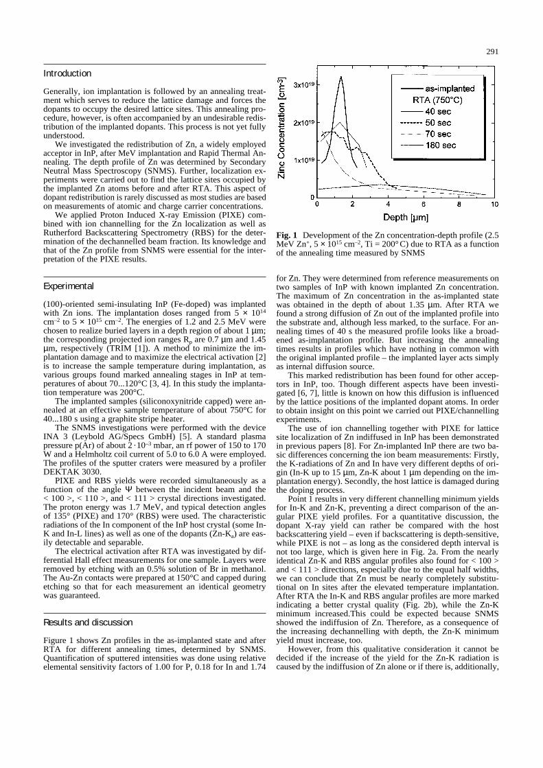
Figure 1 shows Zn profiles in the as-implanted state and afterRTA for different annealing times, determined by SNMS.Quantification of sputtered intensities was done using relativeelemental sensitivity factors of 1.00 for P, 0.18 for In and 1.74
for Zn. They were determined from reference measurements ontwo samples of InP with known implanted Zn concentration.The maximum of Zn concentration in the as-implanted statewas obtained in the depth of about 1.35 µm. After RTA wefound a strong diffusion of Zn out of the implanted profile intothe substrate and, although less marked, to the surface. For an-nealing times of 40 s the measured profile looks like a broad-ened as-implantation profile. But increasing the annealingtimes results in profiles which have nothing in common withthe original implanted profile – the implanted layer acts simplyas internal diffusion source.
This marked redistribution has been found for other accep-tors in InP, too. Though different aspects have been investi-gated [6, 7], little is known on how this diffusion is influencedby the lattice positions of the implanted dopant atoms. In orderto obtain insight on this point we carried out PIXE/channellingexperiments.
The use of ion channelling together with PIXE for latticesite localization of Zn indiffused in InP has been demonstratedin previous papers [8]. For Zn-implanted InP there are two ba-sic differences concerning the ion beam measurements: Firstly,the K-radiations of Zn and In have very different depths of ori-gin (In-K up to 15 µm, Zn-K about 1 µm depending on the im-plantation energy). Secondly, the host lattice is damaged duringthe doping process.
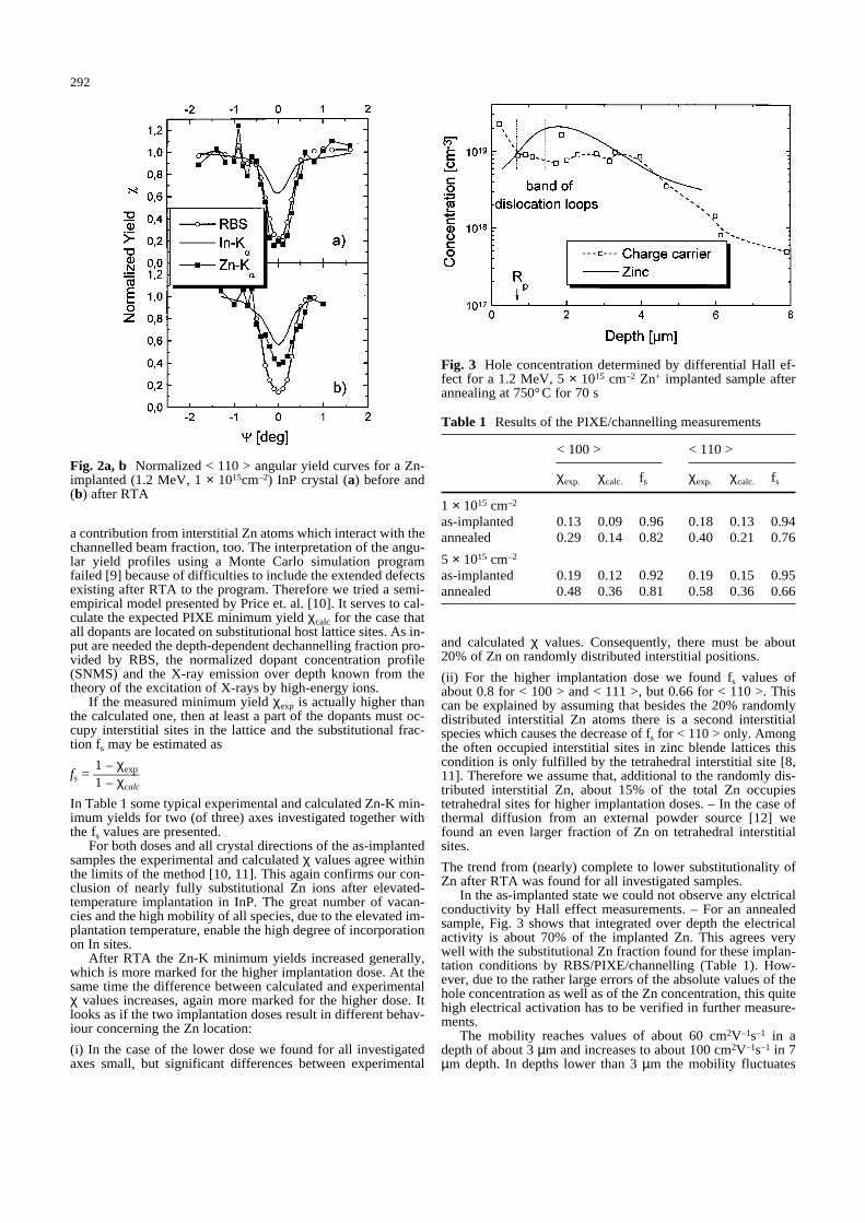
Point 1 results in very different channelling minimum yieldsfor In-K and Zn-K, preventing a direct comparison of the an-gular PIXE yield profiles. For a quantitative discussion, thedopant X-ray yield can rather be compared with the hostbackscattering yield – even if backscattering is depth-sensitive,while PIXE is not – as long as the considered depth interval isnot too large, which is given here in Fig. 2a. From the nearlyidentical Zn-K and RBS angular profiles also found for < 100 >and < 111 > directions, especially due to the equal half widths,we can conclude that Zn must be nearly completely substitu-tional on In sites after the elevated temperature implantation.After RTA the In-K and RBS angular profiles are more markedindicating a better crystal quality (Fig. 2b), while the Zn-Kminimum increased.This could be expected because SNMSshowed the indiffusion of Zn. Therefore, as a consequence ofthe increasing dechannelling with depth, the Zn-K minimumyield must increase, too.
However, from this qualitative consideration it cannot bedecided if the increase of the yield for the Zn-K radiation iscaused by the indiffusion of Zn alone or if there is, additionally,
291
Fig. 1 Development of the Zn concentration-depth profile (2.5MeV Zn+, 5 × 1015 cm–2, Ti = 200°C) due to RTA as a functionof the annealing time measured by SNMS
a contribution from interstitial Zn atoms which interact with thechannelled beam fraction, too. The interpretation of the angu-lar yield profiles using a Monte Carlo simulation programfailed [9] because of difficulties to include the extended defectsexisting after RTA to the program. Therefore we tried a semi-empirical model presented by Price et. al. [10]. It serves to cal-culate the expected PIXE minimum yield χcalc for the case thatall dopants are located on substitutional host lattice sites. As in-put are needed the depth-dependent dechannelling fraction pro-vided by RBS, the normalized dopant concentration profile(SNMS) and the X-ray emission over depth known from thetheory of the excitation of X-rays by high-energy ions.
If the measured minimum yield χexp is actually higher thanthe calculated one, then at least a part of the dopants must oc-cupy interstitial sites in the lattice and the substitutional frac-tion fs may be estimated as
1 – χexpfs = –––––––1 – χcalc
In Table 1 some typical experimental and calculated Zn-K min-imum yields for two (of three) axes investigated together withthe fs values are presented.
For both doses and all crystal directions of the as-implantedsamples the experimental and calculated χ values agree withinthe limits of the method [10, 11]. This again confirms our con-clusion of nearly fully substitutional Zn ions after elevated-temperature implantation in InP. The great number of vacan-cies and the high mobility of all species, due to the elevated im-plantation temperature, enable the high degree of incorporationon In sites.
After RTA the Zn-K minimum yields increased generally,which is more marked for the higher implantation dose. At thesame time the difference between calculated and experimentalχ values increases, again more marked for the higher dose. Itlooks as if the two implantation doses result in different behav-iour concerning the Zn location:
(i) In the case of the lower dose we found for all investigatedaxes small, but significant differences between experimental
and calculated χ values. Consequently, there must be about20% of Zn on randomly distributed interstitial positions.
(ii) For the higher implantation dose we found fs values ofabout 0.8 for < 100 > and < 111 >, but 0.66 for < 110 >. Thiscan be explained by assuming that besides the 20% randomlydistributed interstitial Zn atoms there is a second interstitialspecies which causes the decrease of fs for < 110 > only. Amongthe often occupied interstitial sites in zinc blende lattices thiscondition is only fulfilled by the tetrahedral interstitial site [8,11]. Therefore we assume that, additional to the randomly dis-tributed interstitial Zn, about 15% of the total Zn occupiestetrahedral sites for higher implantation doses. – In the case ofthermal diffusion from an external powder source [12] wefound an even larger fraction of Zn on tetrahedral interstitialsites.
The trend from (nearly) complete to lower substitutionality ofZn after RTA was found for all investigated samples.
In the as-implanted state we could not observe any elctricalconductivity by Hall effect measurements. – For an annealedsample, Fig. 3 shows that integrated over depth the electricalactivity is about 70% of the implanted Zn. This agrees verywell with the substitutional Zn fraction found for these implan-tation conditions by RBS/PIXE/channelling (Table 1). How-ever, due to the rather large errors of the absolute values of thehole concentration as well as of the Zn concentration, this quitehigh electrical activation has to be verified in further measure-ments.
The mobility reaches values of about 60 cm2V–1s–1 in adepth of about 3 µm and increases to about 100 cm2V–1s–1 in 7µm depth. In depths lower than 3 µm the mobility fluctuates
292
Table 1 Results of the PIXE/channelling measurements
< 100 > < 110 >
χexp. χcalc. fs χexp. χcalc. fs
1 × 1015 cm–2
as-implanted 0.13 0.09 0.96 0.18 0.13 0.94annealed 0.29 0.14 0.82 0.40 0.21 0.76
5 × 1015 cm–2
as-implanted 0.19 0.12 0.92 0.19 0.15 0.95annealed 0.48 0.36 0.81 0.58 0.36 0.66
Fig. 2a, b Normalized < 110 > angular yield curves for a Zn-implanted (1.2 MeV, 1 × 1015cm–2) InP crystal (a) before and(b) after RTA
Fig. 3 Hole concentration determined by differential Hall ef-fect for a 1.2 MeV, 5 × 1015 cm–2 Zn+ implanted sample afterannealing at 750°C for 70 s
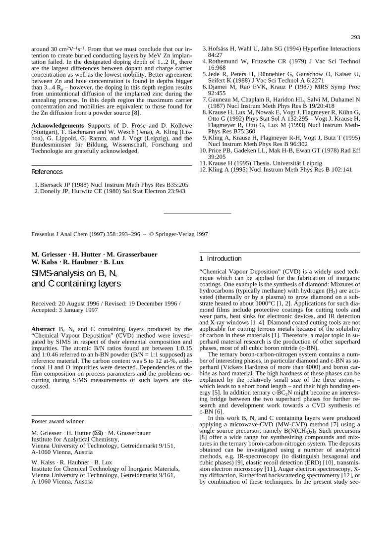
around 30 cm2V–1s–1. From that we must conclude that our in-tention to create buried conducting layers by MeV Zn implan-tation failed. In the designated doping depth of 1...2 Rp thereare the largest differences between dopant and charge carrierconcentration as well as the lowest mobility. Better agreementbetween Zn and hole concentration is found in depths biggerthan 3...4 Rp – however, the doping in this depth region resultsfrom unintentional diffusion of the implanted zinc during theannealing process. In this depth region the maximum carrierconcentration and mobilities are equivalent to those found forthe Zn diffusion from a powder source [8].
Acknowledgements Supports of D. Fröse and D. Kollewe(Stuttgart), T. Bachmann and W. Wesch (Jena), A. Kling (Lis-boa), G. Lippold, G. Ramm, and J. Vogt (Leipzig), and theBundesminister für Bildung, Wissenschaft, Forschung undTechnologie are gratefully acknowledged.
References
1. Biersack JP (1988) Nucl Instrum Meth Phys Res B35:2052. Donelly JP, Hurwitz CE (1980) Sol Stat Electron 23:943
3.Hofsäss H, Wahl U, Jahn SG (1994) Hyperfine Interactions84:27
4.Rothemund W, Fritzsche CR (1979) J Vac Sci Technol16:968
5. Jede R, Peters H, Dünnebier G, Ganschow O, Kaiser U,Seifert K (1988) J Vac Sci Technol A 6:2271
6.Djamei M, Rao EVK, Krauz P (1987) MRS Symp Proc92:455
7.Gauneau M, Chaplain R, Haridon HL, Salvi M, Duhamel N(1987) Nucl Instrum Meth Phys Res B 19/20:418
8.Krause H, Lux M, Nowak E, Vogt J, Flagmeyer R, Kühn G,Otto G (1992) Phys Stat Sol A 132:295 – Vogt J, Krause H,Flagmeyer R, Otto G, Lux M (1993) Nucl Instrum Meth-Phys Res B75:360
9.Kling A, Krause H, Flagmeyer R-H, Vogt J, Butz T (1995)Nucl Instrum Meth Phys Res B 96:302
10.Price PB, Gadeken LL, Mak H-B, Ewan GT (1978) Rad Eff39:205
11.Krause H (1995) Thesis. Universität Leipzig12.Kling A (1995) Nucl Instrum Meth Phys Res B 102:141
293
Fresenius J Anal Chem (1997) 358 :293–296 – © Springer-Verlag 1997
M. Griesser · H. Hutter · M. Grasserbauer ·W. Kalss · R. Haubner · B. Lux
SIMS-analysis on B, N, and C containing layers
Received: 20 August 1996 / Revised: 19 December 1996 / Accepted: 3 January 1997
Abstract B, N, and C containing layers produced by the“Chemical Vapour Deposition” (CVD) method were investi-gated by SIMS in respect of their elemental composition andimpurities. The atomic B/N ratios found are between 1:0.15and 1:0.46 referred to an h-BN powder (B/N = 1:1 supposed) asreference material. The carbon content was 5 to 12 at-%, addi-tional H and O impurities were detected. Dependencies of thefilm composition on process parameters and the problems oc-curring during SIMS measurements of such layers are dis-cussed.
1 Introduction
“Chemical Vapour Deposition” (CVD) is a widely used tech-nique which can be applied for the fabrication of inorganiccoatings. One example is the synthesis of diamond: Mixtures ofhydrocarbons (typically methane) with hydrogen (H2) are acti-vated (thermally or by a plasma) to grow diamond on a sub-strate heated to about 1000°C [1, 2]. Applications for such dia-mond films include protective coatings for cutting tools andwear parts, heat sinks for electronic devices, and IR detectionand X-ray windows [1–4]. Diamond coated cutting tools are notapplicable for cutting ferrous metals because of the solubilityof carbon in these materials [1]. Therefore, a major topic in su-perhard material research is the production of other superhardphases, most of all cubic boron nitride (c-BN).
The ternary boron-carbon-nitrogen system contains a num-ber of interesting phases, in particular diamond and c-BN as su-perhard (Vickers Hardness of more than 4000) and boron car-bide as hard material. The high hardness of these phases can beexplained by the relatively small size of the three atoms –which leads to a short bond length – and their high bonding en-ergy [5]. In addition ternary c-BC2N might become an interest-ing bridge between the two superhard phases for further re-search and development work towards a CVD synthesis of c-BN [6].
In this work B, N, and C containing layers were producedapplying a microwave-CVD (MW-CVD) method [7] using asingle source precursor, namely B(N(CH3)2)3. Such precursors[8] offer a wide range for synthesizing compounds and mix-tures in the ternary boron-carbon-nitrogen system. The depositsobtained can be investigated using a number of analyticalmethods, e.g. IR-spectroscopy (to distinguish hexagonal andcubic phases) [9], elastic recoil detection (ERD) [10], transmis-sion electron microscopy [11], Auger electron spectroscopy, X-ray diffraction, Rutherford backscattering spectrometry [12], orby combination of these techniques. In the present study sec-
Poster award winner
M. Griesser · H. Hutter (Y) · M. GrasserbauerInstitute for Analytical Chemistry, Vienna University of Technology, Getreidemarkt 9/151, A-1060 Vienna, Austria
W. Kalss · R. Haubner · B. LuxInstitute for Chemical Technology of Inorganic Materials, Vienna University of Technology, Getreidemarkt 9/161, A-1060 Vienna, Austria