Embed Size (px)
Citation preview
Name:
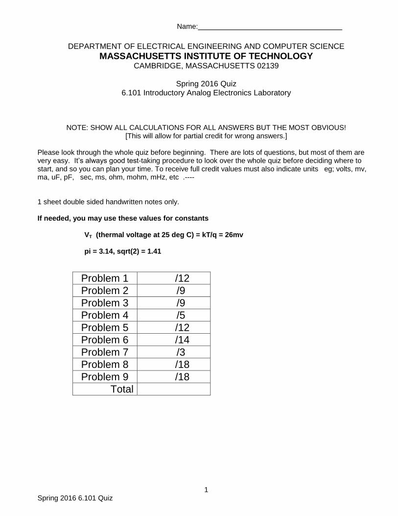
1 Spring 2016 6.101 Quiz
DEPARTMENT OF ELECTRICAL ENGINEERING AND COMPUTER SCIENCE
MASSACHUSETTS INSTITUTE OF TECHNOLOGY CAMBRIDGE, MASSACHUSETTS 02139
Spring 2016 Quiz
6.101 Introductory Analog Electronics Laboratory
NOTE: SHOW ALL CALCULATIONS FOR ALL ANSWERS BUT THE MOST OBVIOUS! [This will allow for partial credit for wrong answers.]
Please look through the whole quiz before beginning. There are lots of questions, but most of them are very easy. It’s always good test-taking procedure to look over the whole quiz before deciding where to start, and so you can plan your time. To receive full credit values must also indicate units eg; volts, mv, ma, uF, pF, sec, ms, ohm, mohm, mHz, etc .---- 1 sheet double sided handwritten notes only. If needed, you may use these values for constants
VT (thermal voltage at 25 deg C) = kT/q = 26mv
pi = 3.14, sqrt(2) = 1.41
Problem 1 /12
Problem 2 /9
Problem 3 /9
Problem 4 /5
Problem 5 /12
Problem 6 /14
Problem 7 /3
Problem 8 /18
Problem 9 /18
Total
2 Spring 2016 6.101
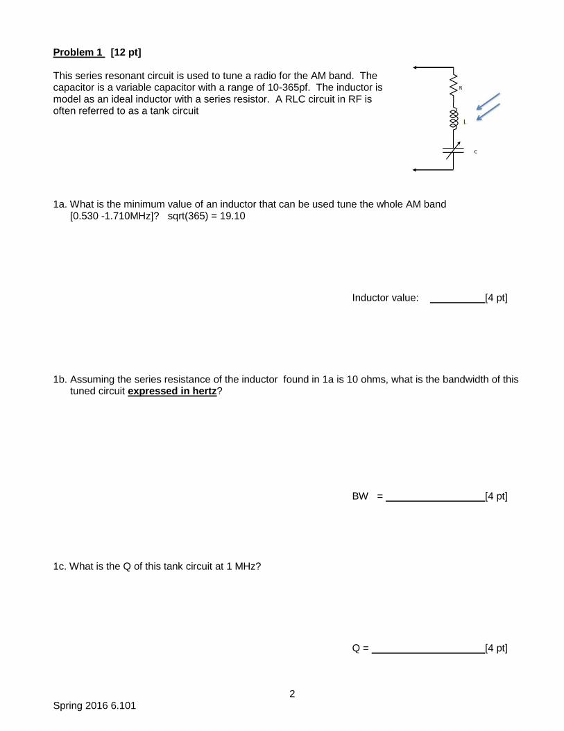
Problem 1 [12 pt] This series resonant circuit is used to tune a radio for the AM band. The capacitor is a variable capacitor with a range of 10-365pf. The inductor is model as an ideal inductor with a series resistor. A RLC circuit in RF is often referred to as a tank circuit 1a. What is the minimum value of an inductor that can be used tune the whole AM band [0.530 -1.710MHz]? sqrt(365) = 19.10 Inductor value: [4 pt] 1b. Assuming the series resistance of the inductor found in 1a is 10 ohms, what is the bandwidth of this tuned circuit expressed in hertz? BW = [4 pt] 1c. What is the Q of this tank circuit at 1 MHz?
Q = [4 pt]
3 Spring 2016 6.101
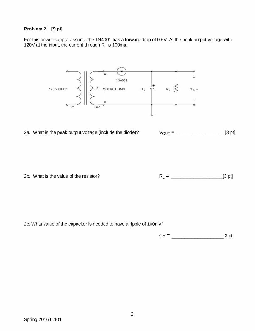
Problem 2 [9 pt] For this power supply, assume the 1N4001 has a forward drop of 0.6V. At the peak output voltage with 120V at the input, the current through RL is 100ma.
2a. What is the peak output voltage (include the diode)? VOUT = _______________[3 pt]
2b. What is the value of the resistor? RL = ________________[3 pt]
2c. What value of the capacitor is needed to have a ripple of 100mv?
CF = ________________[3 pt]
4 Spring 2016 6.101
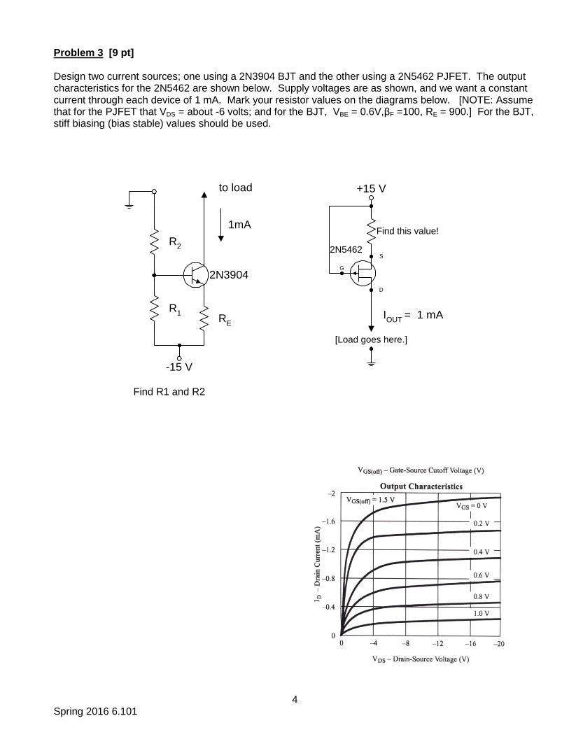
Problem 3 [9 pt] Design two current sources; one using a 2N3904 BJT and the other using a 2N5462 PJFET. The output characteristics for the 2N5462 are shown below. Supply voltages are as shown, and we want a constant current through each device of 1 mA. Mark your resistor values on the diagrams below. [NOTE: Assume that for the PJFET that VDS = about -6 volts; and for the BJT, VBE = 0.6V,βF =100, RE = 900.] For the BJT, stiff biasing (bias stable) values should be used.
2N3904
R2
RE
R1
to load
1mA
-15 V
Find this value!
+15 V
IOUT
= 1 mA
2N5462
G
D
S
[Load goes here.]
Find R1 and R2
5 Spring 2016 6.101
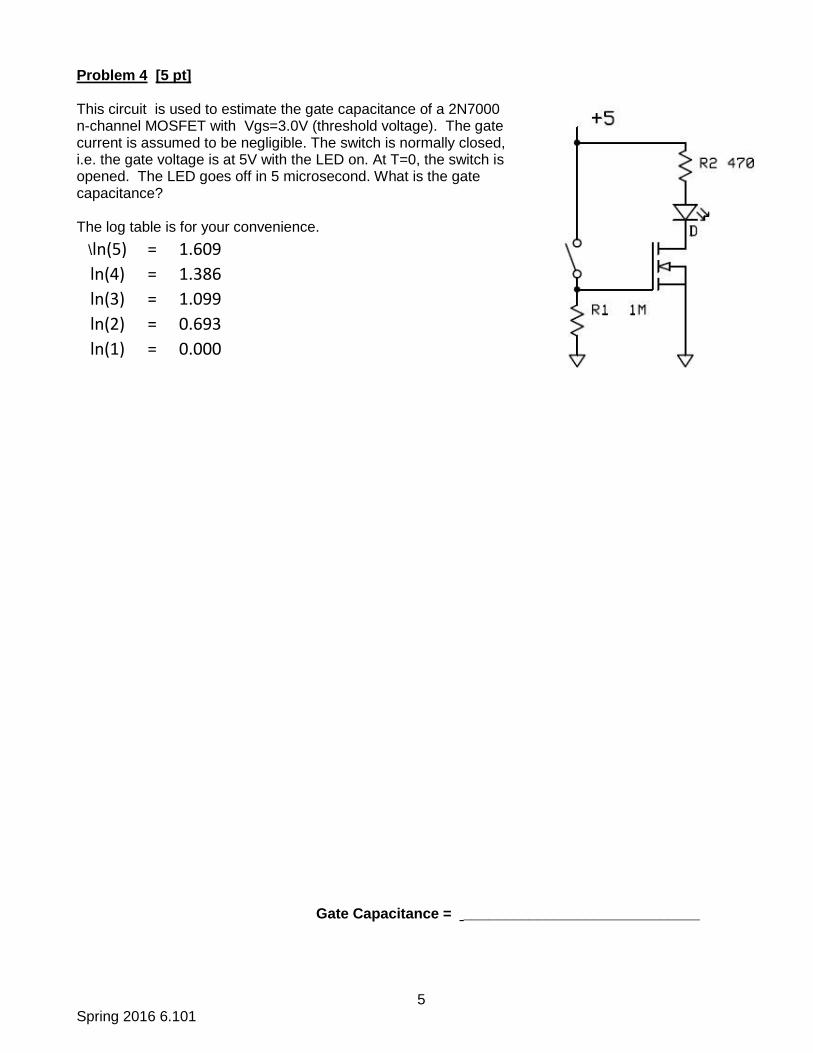
Problem 4 [5 pt] This circuit is used to estimate the gate capacitance of a 2N7000 n-channel MOSFET with Vgs=3.0V (threshold voltage). The gate current is assumed to be negligible. The switch is normally closed, i.e. the gate voltage is at 5V with the LED on. At T=0, the switch is opened. The LED goes off in 5 microsecond. What is the gate capacitance? The log table is for your convenience.
\ln(5) = 1.609
ln(4) = 1.386
ln(3) = 1.099
ln(2) = 0.693
ln(1) = 0.000
Gate Capacitance = _____________________________
6 Spring 2016 6.101
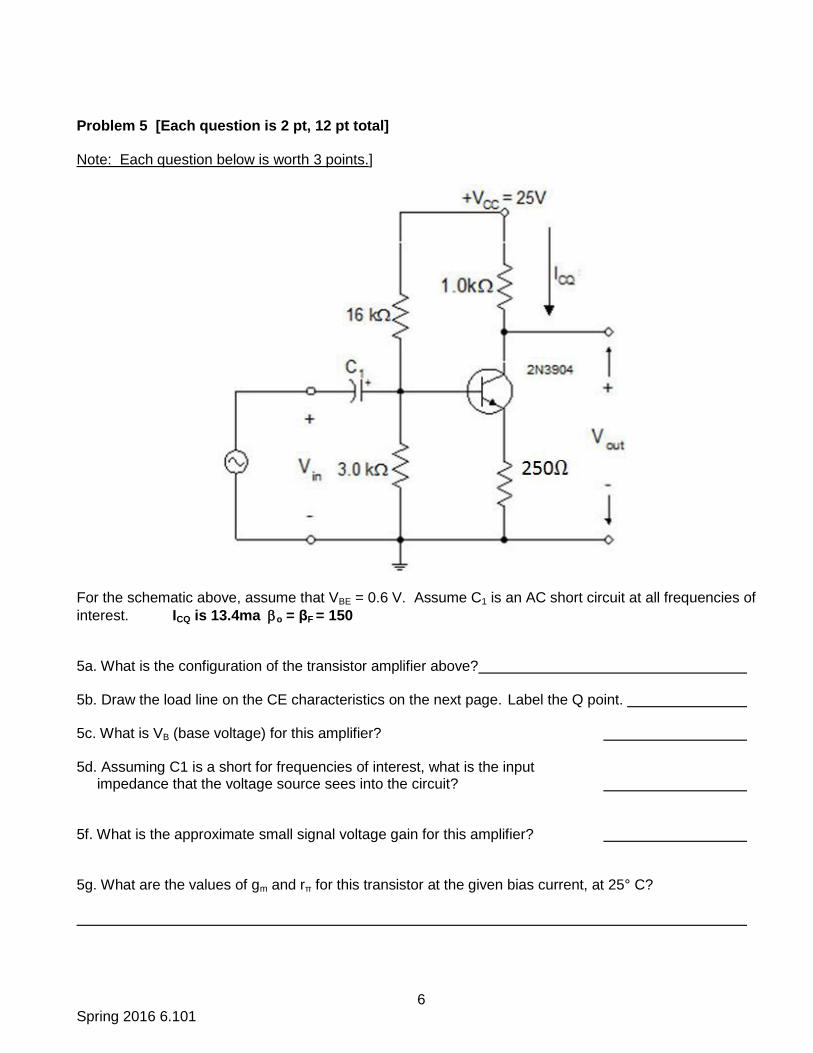
Problem 5 [Each question is 2 pt, 12 pt total] Note: Each question below is worth 3 points.]
For the schematic above, assume that VBE = 0.6 V. Assume C1 is an AC short circuit at all frequencies of
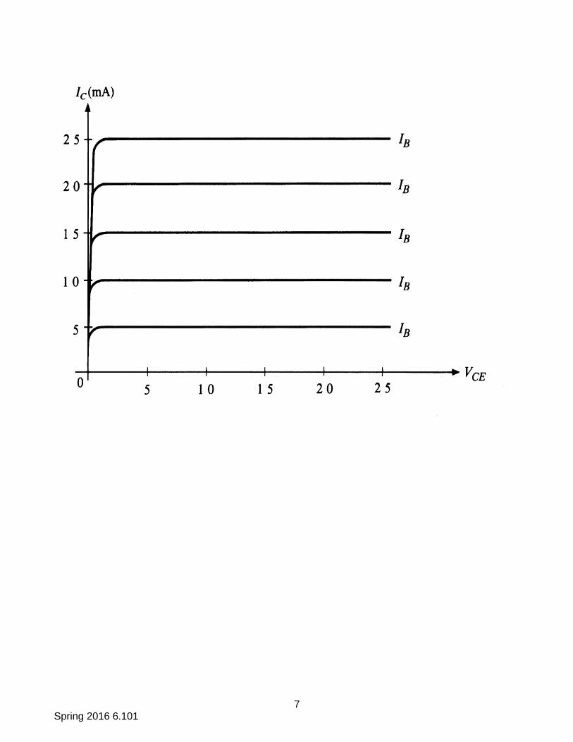
interest. ICQ is 13.4ma o = βF = 150 5a. What is the configuration of the transistor amplifier above? 5b. Draw the load line on the CE characteristics on the next page. Label the Q point. 5c. What is VB (base voltage) for this amplifier? 5d. Assuming C1 is a short for frequencies of interest, what is the input impedance that the voltage source sees into the circuit? 5f. What is the approximate small signal voltage gain for this amplifier? 5g. What are the values of gm and rπ for this transistor at the given bias current, at 25° C?
7 Spring 2016 6.101
8 Spring 2016 6.101
+
Vout
_
Q1
Q2
D2
1N914
D1 IN914 R
E= 1.0
330
+45 V
-45 V
+45 V
330
-45 V
RE=
1.0
RL= 10
VIN
Node 1
F = 25
F = 25
E1
B1
B2
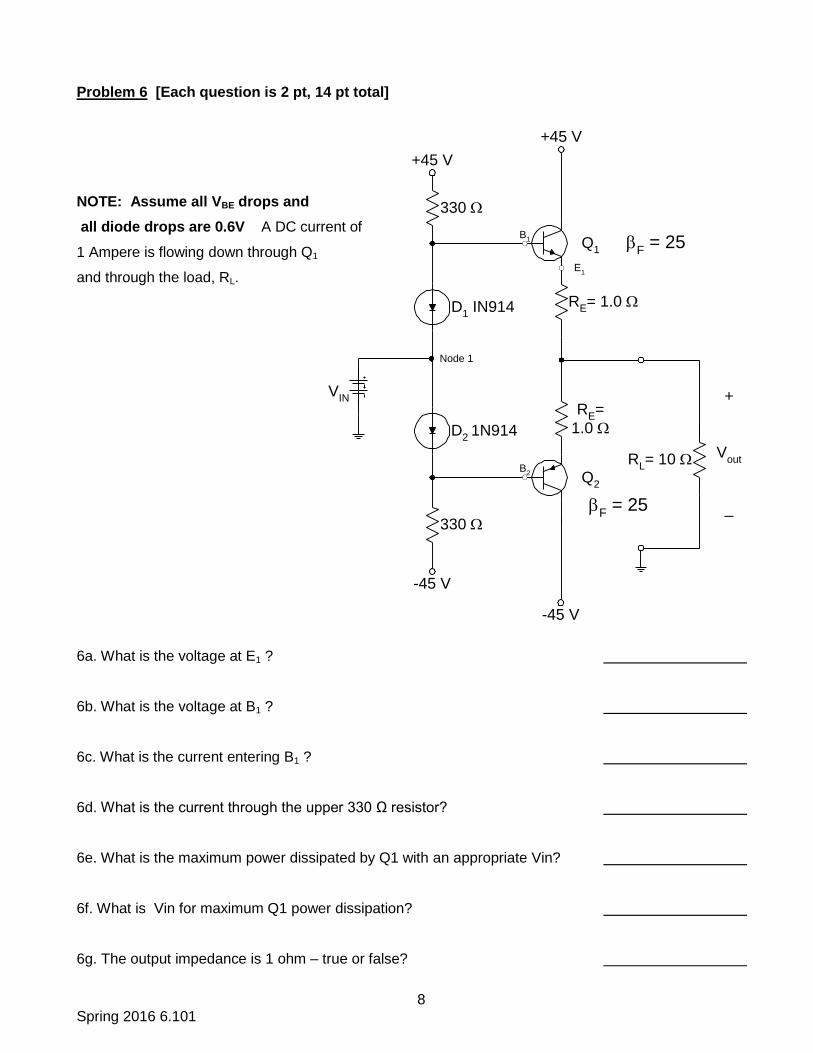
Problem 6 [Each question is 2 pt, 14 pt total]
NOTE: Assume all VBE drops and
all diode drops are 0.6V A DC current of
1 Ampere is flowing down through Q1
and through the load, RL.
6a. What is the voltage at E1 ?
6b. What is the voltage at B1 ?
6c. What is the current entering B1 ?
6d. What is the current through the upper 330 Ω resistor?
6e. What is the maximum power dissipated by Q1 with an appropriate Vin?
6f. What is Vin for maximum Q1 power dissipation?
6g. The output impedance is 1 ohm – true or false?
9 Spring 2016 6.101
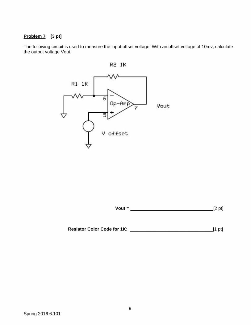
Problem 7 [3 pt] The following circuit is used to measure the input offset voltage. With an offset voltage of 10mv, calculate the output voltage Vout.
Vout = _________________________________[2 pt]
Resistor Color Code for 1K: _________________________________[1 pt]
10 Spring 2016 6.101
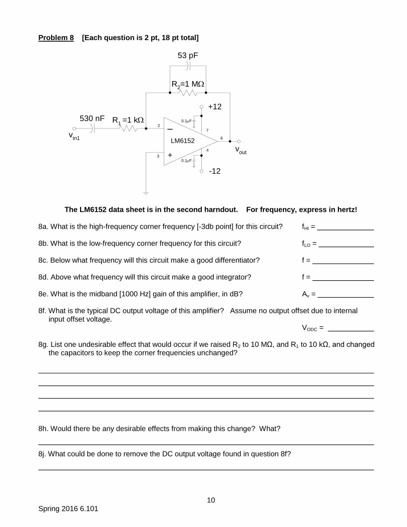
Problem 8 [Each question is 2 pt, 18 pt total]
The LM6152 data sheet is in the second harndout. For frequency, express in hertz!
8a. What is the high-frequency corner frequency [-3db point] for this circuit? fHI = 8b. What is the low-frequency corner frequency for this circuit? fLO = 8c. Below what frequency will this circuit make a good differentiator? f = 8d. Above what frequency will this circuit make a good integrator? f = 8e. What is the midband [1000 Hz] gain of this amplifier, in dB? Av = 8f. What is the typical DC output voltage of this amplifier? Assume no output offset due to internal input offset voltage. VODC = 8g. List one undesirable effect that would occur if we raised R2 to 10 MΩ, and R1 to 10 kΩ, and changed the capacitors to keep the corner frequencies unchanged?
8h. Would there be any desirable effects from making this change? What?
8j. What could be done to remove the DC output voltage found in question 8f?
vout
–
+
LM6152
2
3
4
7
6
R2=1 M
+12
-12
0.1F
0.1F
53 pF
R1
=1 k530 nF
vin1
11 Spring 2016 6.101
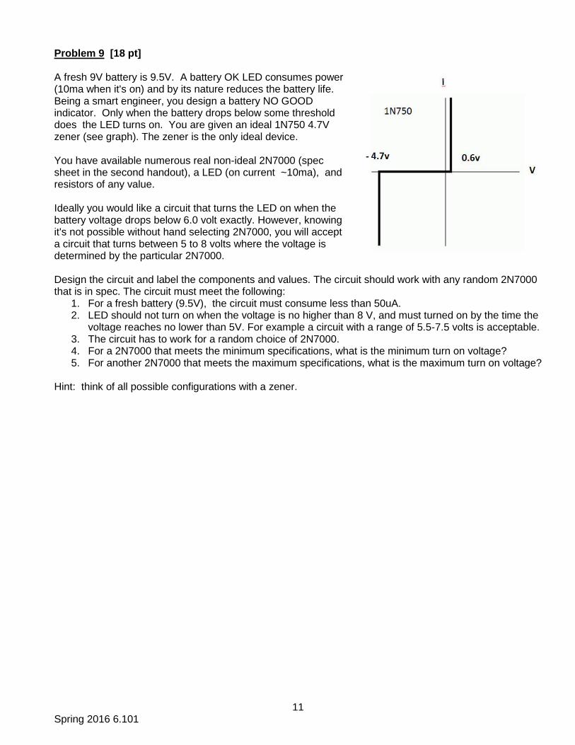
Problem 9 [18 pt] A fresh 9V battery is 9.5V. A battery OK LED consumes power (10ma when it's on) and by its nature reduces the battery life. Being a smart engineer, you design a battery NO GOOD indicator. Only when the battery drops below some threshold does the LED turns on. You are given an ideal 1N750 4.7V zener (see graph). The zener is the only ideal device. You have available numerous real non-ideal 2N7000 (spec sheet in the second handout), a LED (on current ~10ma), and resistors of any value. Ideally you would like a circuit that turns the LED on when the battery voltage drops below 6.0 volt exactly. However, knowing it's not possible without hand selecting 2N7000, you will accept a circuit that turns between 5 to 8 volts where the voltage is determined by the particular 2N7000. Design the circuit and label the components and values. The circuit should work with any random 2N7000 that is in spec. The circuit must meet the following:
1. For a fresh battery (9.5V), the circuit must consume less than 50uA. 2. LED should not turn on when the voltage is no higher than 8 V, and must turned on by the time the
voltage reaches no lower than 5V. For example a circuit with a range of 5.5-7.5 volts is acceptable. 3. The circuit has to work for a random choice of 2N7000. 4. For a 2N7000 that meets the minimum specifications, what is the minimum turn on voltage? 5. For another 2N7000 that meets the maximum specifications, what is the maximum turn on voltage?
Hint: think of all possible configurations with a zener.

12 Spring 2016 6.101
Problem 9 Solution page
Minimun turn on voltage: _______________________________________
Maximum turn on voltage: _______________________________________