Embed Size (px)
Citation preview
Pertanika J. Sci. & Techno!. 13(2): 213 - 235 (2005)ISSN: 0128-7680
© Universiti Putra Malaysia Press
Derivation of Bearing Capacity Equation for a Two LayeredSystem of Weak Clay Layer Overlaid by Dense Sand Layer
AbdulhaHz O. Al-Shenawy & Awad A. Al-KarniKing Saud University, Civil Eng. Dept., P. O. Box 800
Riyadh, 11421, Saudi Arabia
Received: 8 May 2003
ABSTRAK
Pengiraan keupayaan galas muktamad tapak cetek ke atas sistem tanah dualapisan bergantung pada corak permukaan kegagalan yang dibangunkan dibawah tapak. Bagi lapisan tanah liat lemah yang dilapisi oleh lapisan pasirtumpat atas, kajian terdahulu menganggap bahawa permukaan kegagalan adalahkegagalan ricih menebuk melalui lapisan pasir atas dan mod kegagalan Prandtldalam lapisan tanah liat lemah bawah. Dengan mengadaptasi anggapan inidalam kajian ini, persamaan keupayaan galas muktamad diperoleh sebagai satufungsi sifat-sifat tanah, kelebaran tapak, dan ketebalan tanah atas. Kertas inimembentangkan kajian berparameter yang terperinci bagi parameter rekabentuk termasuk kesan sudut geseran, nisbah ketebalan lapisan pasir dengankelebaran tapak, nisbah kedalaman pembenaman dengan kelebaran tapak, dannisbah kejeleketan tanah liat dengan keluaran berat unit tanah liat olehkelebaran tapak. Carta reka bentuk dibangunkan dalam bentuk tiada dimensiuntuk julat parameter reka bentuk yang sangat luas. Carta yang barn memberipilihan lain kepada sesiapa yang percaya bahawa carta reka bentuk dibangunkanberdasarkan analisis had atas lebih anggar keupayaan galas disebabkan sifatpenyelesaian had atas. Carta reka bentuk barn adalah terhad kepada tapak cetek.
ABSTRACT
Calculation of the ultimate bearing capacity of shallow footing on a two layeredsystem of soil depends on the pattern of the failure surface that develops belowthe footing. For a weak clay layer overlaid by a top dense sand layer, previousstudies assumed that the failure surface is a punching shear failure through theupper sand layer and Prandtl's failure mode in the bottom weak clay layer. Byadapting this assumption in this study, the ultimate bearing capacity equationwas derived as a function of the properties of soils, the footing width, and thetopsoil thickness. The paper presents a detailed parametric study of the designparameters including the effect of angle of friction, the ratio of the thicknessof sand layer to the footing width, the ratio of the depth of embedment to thefooting width, and the ratio of the clay soil cohesion to the product of the clayunit weight by the footing width. Design charts were developed in dimensionlessform for very wide ranges of design parameters. The available method based onthe limit equalibrium analysis was developed in dimensionlised form and for alimited range of design parametrs. The new charts give another option forthose who believe that the design charts developed based on the upper limitanalysis overestimate the bearing capacity due to the very nature of the upperbound solution. The new design charts are limited to shallow footings.
Keywords: Shallow footing, bearing capacity, two layered system, weak claylayer, dense sand layer, design chart
Abdulhafiz O. AJ-Shenawy & Awad A. AJ-Karni
INTRODUCTION
The function of a foundation is to transfer the load of the superstructure to theunderlying soil formation without overstressing the soil. The soil must becapable of carrying the load for structure(s) placed upon it without shearfailure and with the resulting settlement being tolerable for that structure.
Many investigations on the subject of ultimate bearing capacity have beencarried out during the past century. Subsequently, numerous proposals havebeen advanced regarding considerations, criteria, and procedures for evaluationof the ultimate bearing capacity of soils. Among the very early contributors werePrandtl (1921) who developed a solution for a surface strip footing over aperfectly plastic cohesive-frictional weightless half-space. Reissner (1924)extended the solution of Prandtl to include the effect of a uniform surchargeload on the resistance of penetration of ultimate applied load. Since real soilspossess weight, Terzaghi (1943) was the first to introduce the concept ofultimate bearing capacity and presented a comprehensive theory for theevaluation of such capacity of shallow foundations. Subsequently, the bearingcapacity theory went through many modifications to account for differentfeatures such as foundation shape, load inclination, ground slope,nonsymmetrical loads, and water table. The general bearing capacity theoriesproposed by Meyerhof (1963), Hansen (1970), Vesic (1973) and others are nowroutinely used in foundation design.
The bearing capacity theories mentioned above involve cases in which thesoil supporting the foundation is homogeneous and extends to a considerabledepth. However, in practice, layered soil profiles are often encountered. Forlayered clayey soil, Button (1953) was the first to analyse footings on layeredsoils of different cohesion. Many other studies were conducted for clayey layersincluding those of Sivareddy and Srinivasan (1967), Brown and Meyerhof(1969), Desai and Reese (1970a, b) and Merifield et al. (1999). In another case,many authors studied the bearing capacity of a sand layer overlaying a claylayer. These studies were conducted by Meyerhof (1974), Meyerhof and Hanna(1978), Hanna and Meyerhof (1980), Hardy and Townsend (1982), Okamuraet at. (1997), Kenny and Andrawes (1996), Burd and Frydman (1997), andMichalowski and Shi (1995). For footings resting over a two-layer c-<j> soil, theultimate bearing capacity was studied by Purushothamaraj et al. (1974),Satyanarayana and Garg (1980), Florkiewicz (1989), and Azam and Wang (1991).
In this study, design charts were developed using the punching shear modelin a dimensionless form since those of Hanna and Meyerhof (1980) were notpresented in a nondimensionlised form, which limits their application. Thenew design charts were developed for very wide ranges of design parameters.The presented charts here may be useful in overcoming the problem of thedesign charts that were developed by Michalowski and Shi (1995) which mayoverestimate the bearing capacity by a significant amount because of the verynature of the upper bound solution on which the derivation is based.
214 PertanikaJ. Sci. & Technol. Vol. 13 0.2,2005
Derivation of Bearing Capacity Equation for a Two Layered System of Weak Clay Layer
FORMUlATION
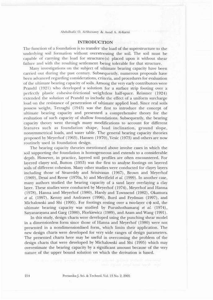
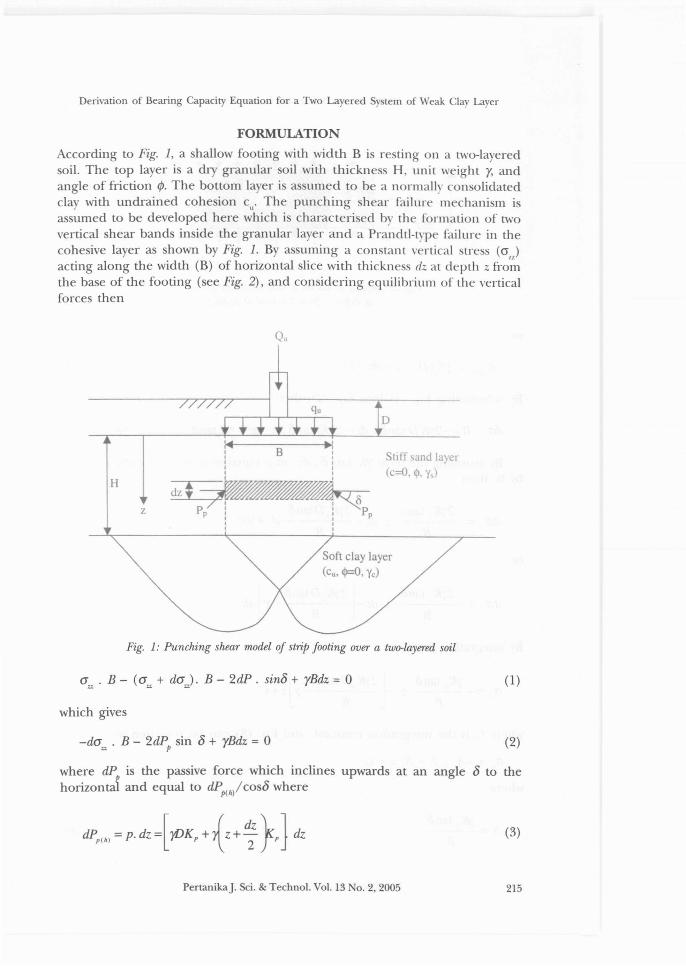
According to Fig. 1, a shallow footing with width B is resting on a two-layeredsoil. The top layer is a dry granular soil with thickness H, unit weight y, andangle of friction I/J. The bottom layer is assumed to be a normally consolidatedclay with undrained cohesion cu' The punching shear failure mechanism isassumed to be developed here which is characterised by the formation of twovertical shear bands inside the granular layer and a Prandtl-type failure in thecohesive layer as shown by Fig. 1. By assuming a constant vertical stress (cr,)acting along the width (B) of horizontal slice with thickness dz at depth z fromthe base of the footing (see Fig. 2), and considering equilibrium of the verticalforces then
Qu
H
z
III,I
~~Pp ! i Pp
I II I
Stlf! sand la)er(c=O. O. y,)
Soft clay layer(cu, ~O. yc)
Fig. 1: Punching shear model of strip footing over a two-layered soil
a . B- (a + da). B- 2dP. sino + yBdz-= 0u u u
which gives
-da . B - 2dP sin 0 + yBdz -= 0u p
(1)
(2)
where dP is the passive force which inclines upwards at an angle 0 to thehorizon~ and equal to dPp(h/cosO where
PertanikaJ. Sci. & Techno!. Vo!. 13 0.2.2005
(3)
215
Abdulhaflz O. AJ-Shenawy & Awad A. AJ-Karni
cra +dcrl1
Fig. 2: Applied forces on a strip dz of the failure zoneat depth z from the base offooting
or
dPP(h) = yKp[D + z + dz /2] .dz
By substituting Eq. (4) into Eq. (2), then
(4)
ria . B = -2yKD rano. dz - 2yKp ran15. z. dz - yKran15. dz. dz + yBdz (5)Z% p p
By assuming the term yKptan 8. dz. dz is equal to zero and dividing Eq. (5)by B, then
2yK tan15 2yK Dtan15dcr:; = p .z . dz - p . dz + )dz
B B
or
2yK tan15 l2yK Dtan15 Jdcr .. = p . z . dz - P - Y .dz.. B B
By integrating Eq.(7)
cr.. = yKP tano .z2_l2yKpDtan15 yJz+c.. B B
where C is the integration constant, and Eq. (8) can be rewritten as
where
yK tan15A =-!:....p--
I B
(6)
(7)
(8)
(9)
(10)
216 PertanikaJ. Sci. & Techno!. Vo!. 13 0.2,2005
Derivation of Bearing Capacity Equation for a Two Layered System of Weak Clay Layer
and
l2yK Dtano rJ-\= P B (11)
By applying the boundary conditions, at z=0; azz=qu and from Eq. (9), then
(12)
and at z=H, a = q where q = 5.14c + y(D + H) and from Eq. (9), thenu up up u
orq = -A H 2 - A H + C
up I ''2 (13)
C = quP + AIH 2 + -\H (14)
Then from Eq.(12) and Eq. (14)
qu = 5.14cu+ y(D + H) + A)H 2 + -\H (15)
By substituting with AI and -\' Eq. (15) can be written in a dimensionlessform as:
~= 5.14S-+ D+K tano(H J+2K tano(D XH)';13 ';13B P B P B B (16)
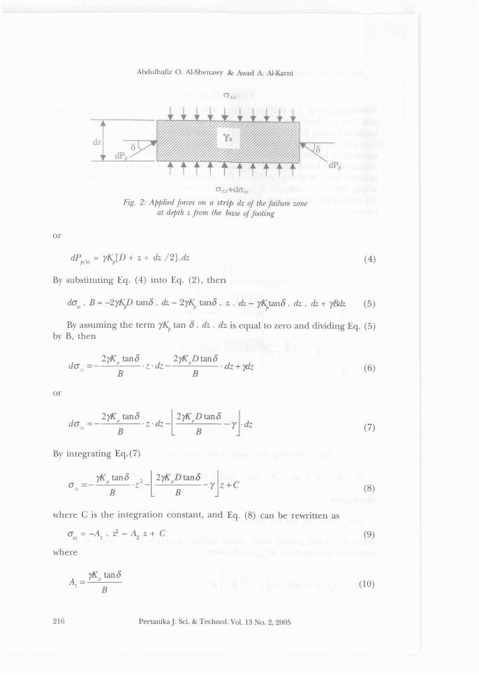
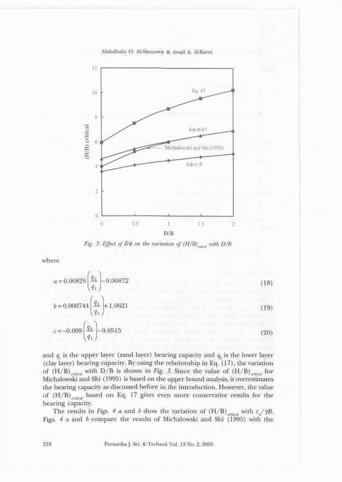
Evaluation of oil/>The effect of the parameter oil/> is a major concern here. Using a high valueof 01 l/> will lead to unconservative results. Fig. 3 shows a comparison between theresults of the variation of (H/B)Critical with D/B at oil/> of 1.0 and 0.67, where(H/B) critical is the ratio of the depth of the sand layer below the footing base tothe footing width at which the clay layer has no effect on the bearing capacity.A significant effect is shown. For example, the (H/B)Critica, at D/B=O is increasedfrom 3.5 to 4.77 when oil/> is decreased from 1.0 to 0.67, respectively. Thedifference between the two values increases as DIB increases. The figure alsoshows a comparison with the results of Michalowski and Shi (1995). The resultsof Michalowski and Shi (1995) show that the value of oil/> is close to one whenH/B is small and reduces as H/B increases. This conclusion is in agreementwith suggestion of Meyerhof (1974). However, the experimental results ofHanna and Meyerhof (1980) suggested lower values of 01 l/>. By using the valuesof oil/> suggested by Hanna and Meyerhof (1980) the following relationshipswere developed
PertanikaJ. Sci. & Technol. Vol. 13 No.2, 2005
(17)
217
Abdulhafiz O. Al-5henawy & Awad A. Al-Kami
12 ,------------------,
10
8
4
~--::::::...,.,::~ Michalowski and Shi (1995)
0/4>=1.0
2
21.50.5
O'-----'-----.L.- '--__--J
oD/B
Fig. 3: Effect of 81¢ on the variation of (H/B)mhad with D/B
where
a =0.00829 [~: )-0.00872
b = 0.000744 [~: } 1.0621
c =-0.009 [~: )-0.0515
(18)
(19)
(20)
and ql is the upper layer (sand layer) bearing capacity and q2 is the lower layer(clay layer) bearing capacity. By using the relationship in Eq. (17), the variationof (H/B\ritical with D/B is shown in Fig. 3. Since the value of (H/B)Critical forMichalowski and Shi (1995) is based on the upper bound analysis, it overestimatesthe bearing capacity as discussed before in the introduction. However, the valueof (H/B) critical based on Eq. 17 gives even more conservative results for thebearing capacity.
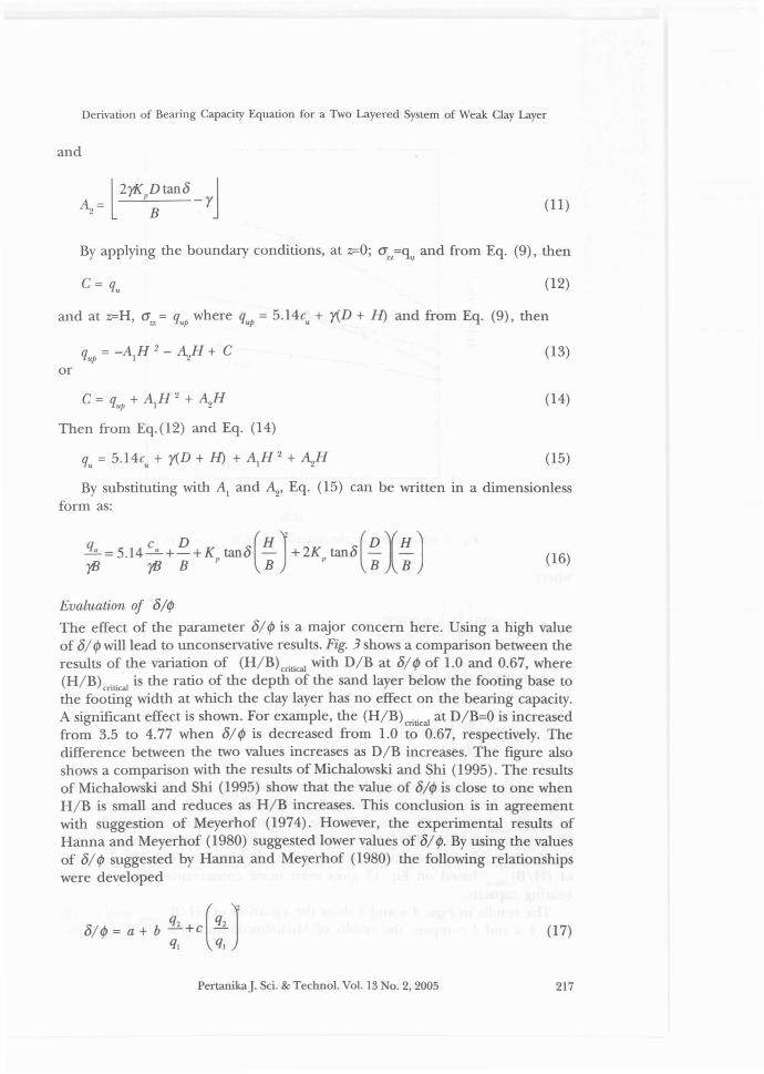
The results in Figs. 4 a and b show the variation of (H/B)CritiCal with c/rB.Figs. 4 a and b compare the results of Michalowski and Shi (1995) with the
218 PertanikaJ. Sci. & Techno!. Vo!. 13 No.2, 2005
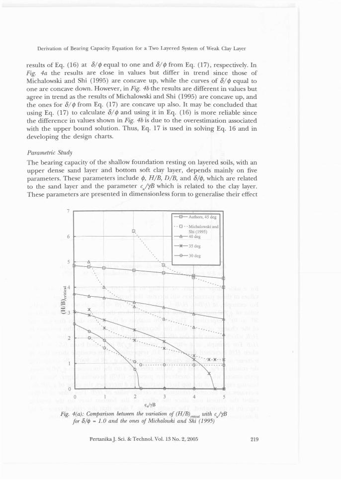
Derivation of Bearing Capacity Equation for a Two Layered System of Weak Clay Layer
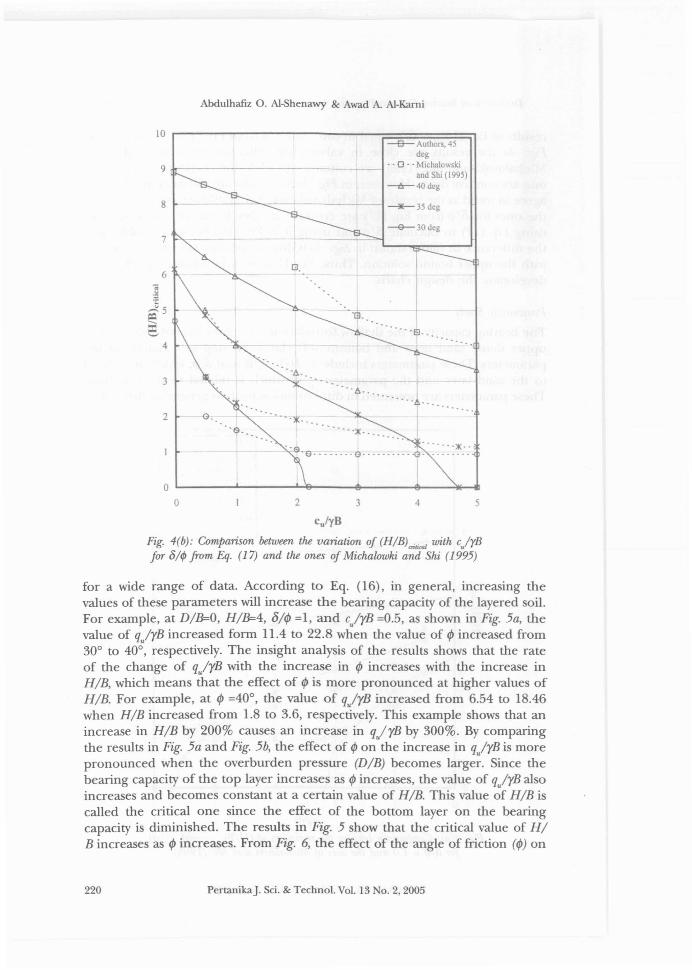
results of Eq. (16) at 8/ I/J equal to one and 8/ I/J from Eq. (17), respectively. InFig. 4a the results are close in values but differ in trend since those ofMichalowski and Shi (1995) are concave up, while the curves of 8/ I/J egual toone are concave down. However, in Fig. 4b the results are different in values butagree in trend as the results of Michalowski and Shi (1995) are concave up, andthe ones for 8/ I/J from Eg. (17) are concave up also. It may be concluded thatusing Eg. (17) to calculate 8/ I/J and using it in Eg. (16) is more reliable sincethe difference in values shown in Fig. 4b is due to the overestimation associatedwith the upper bound solution. Thus, Eg. 17 is used in solving Eg. 16 and indeveloping the design charts.
Parametric Study
The bearing capacity of the shallow foundation resting on layered soils, with anupper dense sand layer and bottom soft clay layer, depends mainly on fiveparameters. These parameters include I/J, H/B, D/B, and 8/1/J, which are relatedto the sand layer and the parameter c/rB which is related to the clay layer.These parameters are presented in dimensionless form to generalise their effect
7--e-- Author. 45 deg
'.6
- - 0 - - Michalow 'ki andSh1(1995)
~---------'-;------1--6--40deg
_.._35deg
~30deg
5G,
"
2
...... ¢.I········ ...
'G. ·--·lK-.
- 'x'G. G-- __ .. __ G-·· -- -- --. -G:: ::~:~.'.'
5432
OL...__.......L..-__.......'-&---4J---~--........,o
cj'YB
Fig. 4(a): Comparison between the variation oJ (H/B)m.rol with e/rBJOT 8/t/J = 1. 0 and the ones oJ Miehawwki and Shi (1995)
PertanikaJ. Sci. & Technol. Vol. 13 0.2,2005 219
Abdulhafiz O. A1-Shenawy & Awad A. A1-Karni
···S..
~30deg
--e-- Authors, 45dcg
.. 0 .. Michalowskiand Shi (1995)
--.!t- 40 dcg
-+-- -ilE--35deg
·.h········· ..,L .
G.
. ..~ .....G.2
3
6
7
8
9...---------
10
·S.. . ..~ .
.·S·O··· .... ·0.. ·· .. ···· G:'::: ::~: ...
5432
OL...---L...----''-&----I!~---e--''*''.....o
cu/yB
Fig. 4(b): Comparison between the variation of (H/B)<rih<al with e.lrBfor 8/¢ from Eq. (17) and the ones of Miehalowki and Shi (1995)
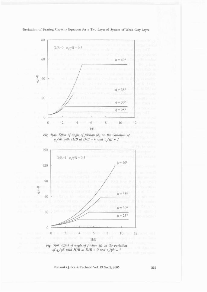
for a wide range of data. According to Eq. (16), in general, increasing thevalues of these parameters will increase the bearing capacity of the layered soil.For example, at DIB=O, HIB=4, ~/4J =1, and e/rB =0.5, as shown in Fig. 5a, thevalue of q/rB increased form 11.4 to 22.8 when the value of 4J increased from30° to 40°, respectively. The insight analysis of the results shows that the rateof the change of q/rB with the increase in 4J increases with the increase inHIB, which means that the effect of 4J is more pronounced at higher values ofHIB. For example, at 4J =40°, the value of q/rB increased from 6.54 to 18.46when HIB increased from 1.8 to 3.6, respectively. This example shows that anincrease in HIB by 200% causes an increase in q/rB by 300%. By comparingthe results in Fig. 5a and Fig. 5b, the effect of 4J on the increase in q/rB is morepronounced when the overburden pressure (DIB) becomes larger. Since thebearing capacity of the top layer increases as 4J increases, the value of q/rB alsoincreases and becomes constant at a certain value of HIB. This value of HIB iscalled the critical one since the effect of the bottom layer on the bearingcapacity is diminished. The results in Fig. 5 show that the critical value of HIB increases as 4J increases. From Fig. 6, the effect of the angle of friction (4J) on
220 PertanikaJ. Sci. & Techno!. Vo!. 13 No.2. 2005
Derivation of Bearing Capacity Equation for a Two Layered System of Weak Clay Layer
80
o B=O CU yB 0.5
60 $ =400
1210
$ = 300
842
oo 6
HlBFig. 5(a): Effect of angle offriction (¢) on the variation of
qJrB with RIB at DIB = 0 and cJrB = 1
20
150
o B=I eirB = 0.5
120
90
1210842
oo 6
HlBFig. 5(b): Effect of angle offriction (fJ on the variation
of qJrB with RIB at DIB = 0 and cJrB = 1
30
60
PertanikaJ. Sci. & Techno!. Vo!. 13 No.2, 2005 221
Abdulhafiz O. AI-8henawy & Awad A. AI-Kami
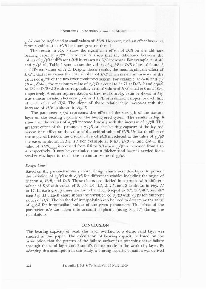
q/rB can be neglected at small values of HIB. However, such an effect becomesmore significant as HIB becomes greater than 1.
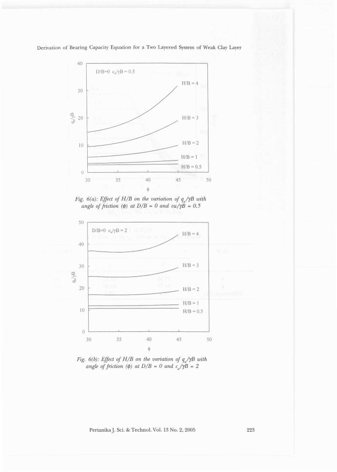
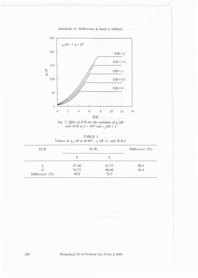
The results in Fig. 7 show the significant effect of DIB on the ultimatebearing capacity q/rB. These results show that the difference between thevalues of q/rB at different DIB increases as HIB increases. For example, at 4>=40and q/rB =1, Table 1 summarises the values of q/rB at DIB values of 0 and 2at different values of HIB. Despite these results, the most significant effect ofDIB is that it increases the critical value of HIB which means an increase in thevalues of q/rB of the two layer combined system. For example, at t/J=40 and q/rB =1, 81t/J=1, the maximum value of q/yB is equal to 54.71 at D/B=O and equalto 182 at D/B=2.0 with corresponding critical values of HIB equal to 6 and 10.6,respectively. Another representation of the results in Fig. 7 can be shown in Fig.8 as a linear variation between q/rB and D/B with different slopes for each lineof each value of HIB. The slope of these relationships increases with theincrease of HIB as shown in Fig. 8.
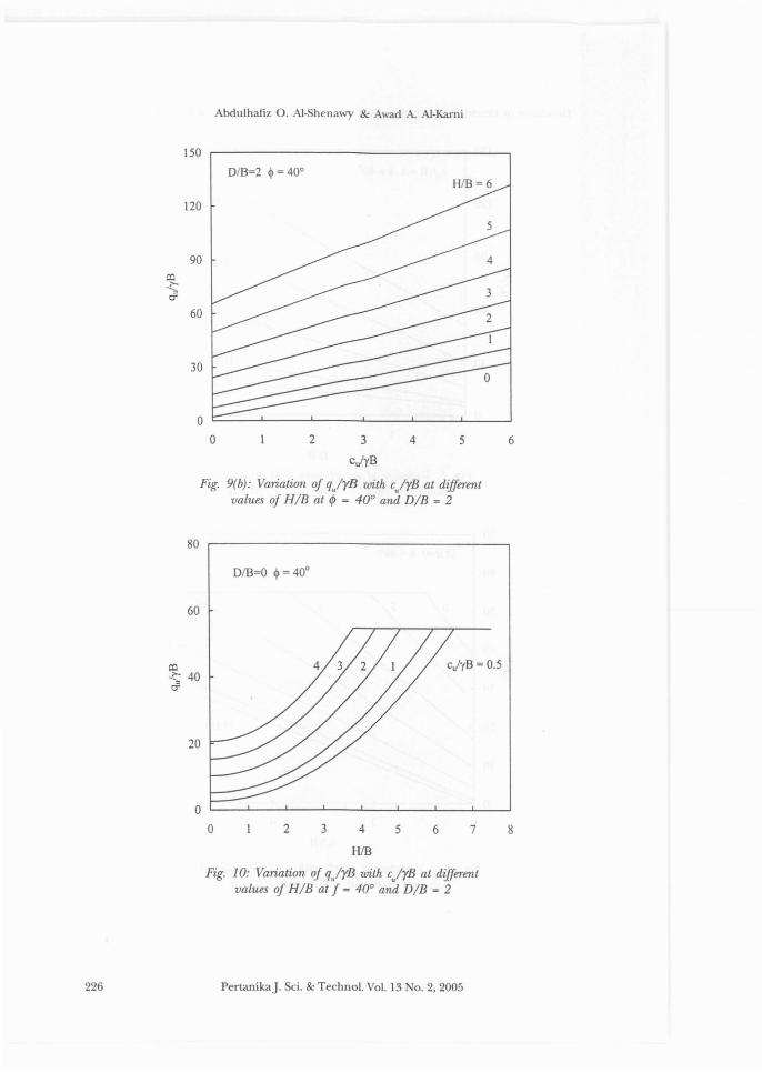
The parameter e/rB represents the effect of the strength of the bottomlayer on the bearing capacity of the two-layered system. The results in Fig. 9show that the values of q/rB increase linearly with the increase of e/rB. Thegreatest effect of the parameter q/rB on the bearing capacity of the layeredsystem is its effect on the value of the critical value of HIB. Unlike th effect ofthe angle of friction, the critical value of HIB is reduced as the value of q/rBincreases as shown in Fig. 10. For example at t/J=40°, DIB =0, and 81t/J=1, thevalue of (HIB)Critial1 is reduced from 6.0 to 3.8 when q/rB is increased from 1 to4, respectively. It may be concluded that a thicker sand layer is needed for aweaker clay layer to reach the maximum value of q/rB.
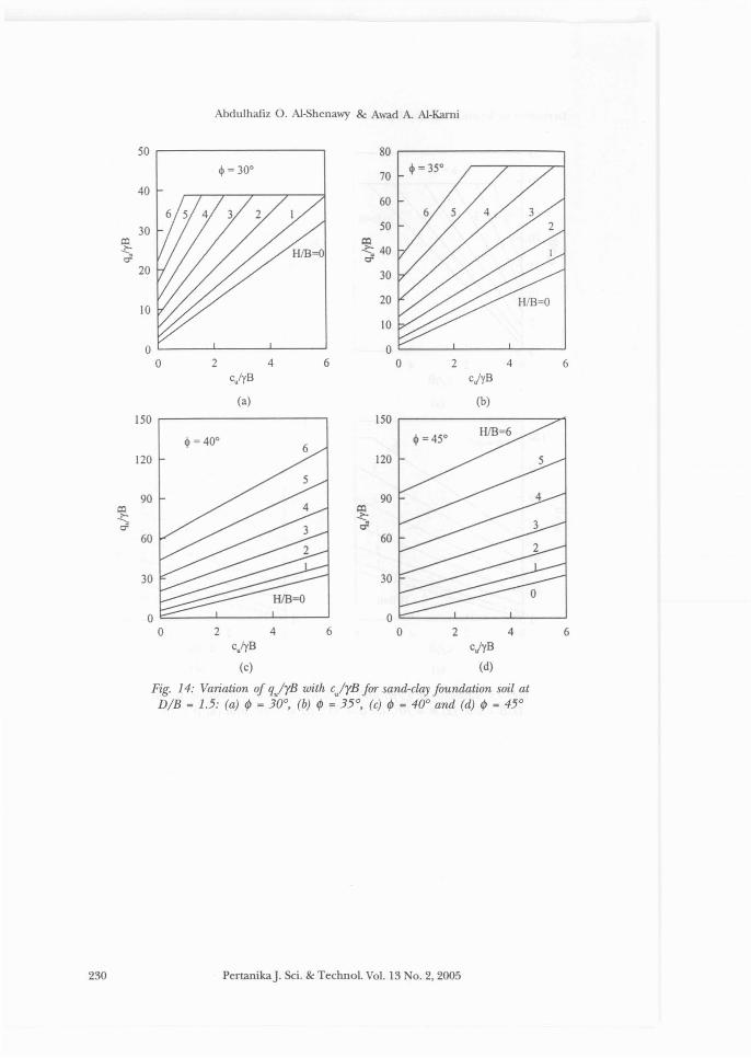
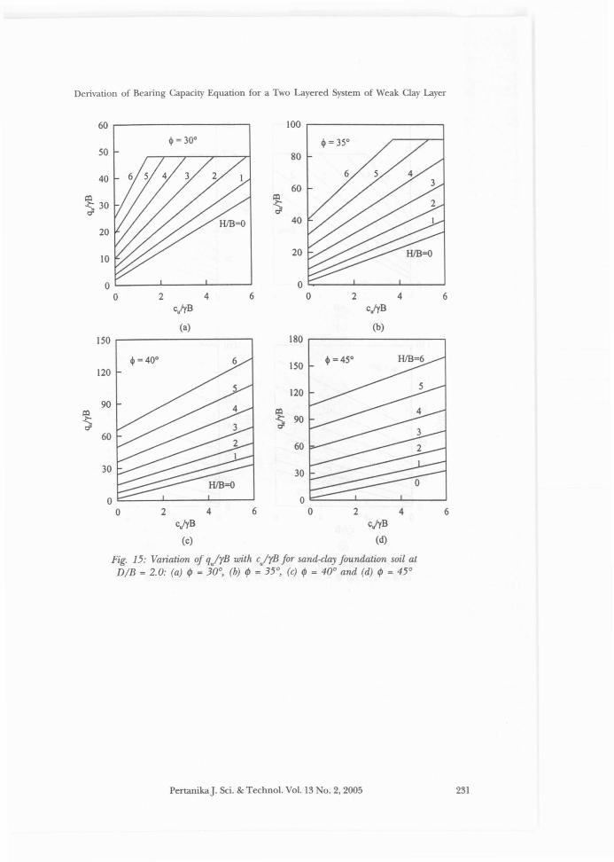
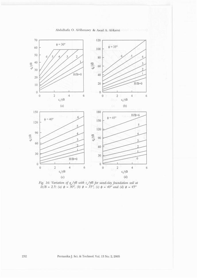
Design Charts
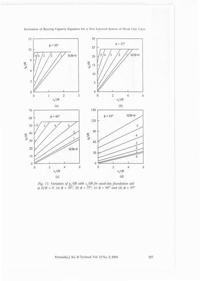
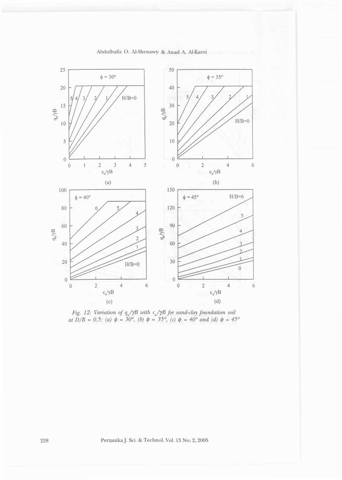
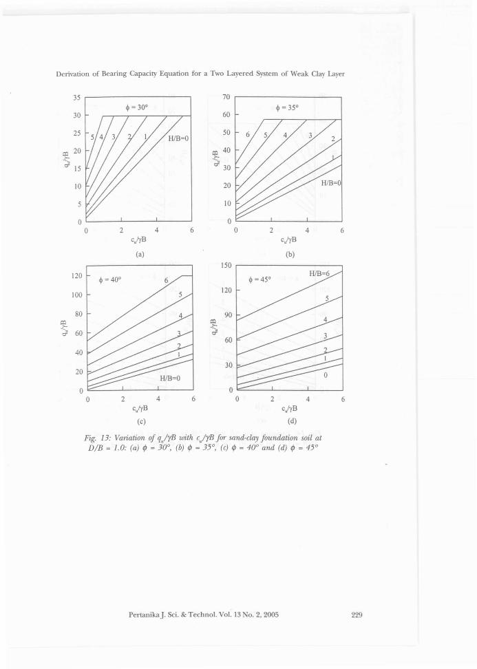
Based on the parametric study above, design charts were developed to presentthe variation of q/rB with e/rB for different variables including the angle offriction 1/>, HIB, and DIB. These charts are divided into groups with differentvalues of DIB with values of 0, 0.5, 1.0, 1.5, 2, 2.5, and 3 as shown in Figs. 11to 17. In each group there are four charts for I/> equal to 30°, 35°, 40°, and 45°(see Fig. 11). Each chart shows the variation of q/rB with e/rB for differentvalues of HIB. The method of interpolation can be used to determine the valueof q/rB for intermediate values of the given parameters. The effect of theparameter 811/> was taken into account implicitly (using Eq. 17) during thecalculations.
CONCLUSION
The bearing capacity of weak clay layer overlaid by a dense sand layer wasstudied in this paper. The calculation of bearing capacity is based on theassumption that the pattern of the failure surface is a punching shear failurethrough the sand layer and Prandtl's failure mode in the weak clay layer. Byadapting this assumption in this study, a bearing capacity equation was derived
222 PertanikaJ. Sci. & Techno!. Vo!. 13 No.2, 2005
Derivation of Bearing Capacity Equation for a Two Layered System of Weak Clay Layer
40
DfB=O cjyB = 0.5
HfB=4
30
co~ 200"
10
11fB=3
HiB=2
HiB= 1
f=============== HfB = 0.5o
30 35 40 45 50
~
Fig. 6(a): Effect of HIB on the variation of qJrB withangle offriction (1/» at DIB = 0 and culrB = 0.5
504540
~
35
DfB=O cjyB = 2H/B =4
HB=3
HfB=2
HfB= 1
HfB = 0.5
o30
10
20
30
50
40
Fig. 6(b): Effect of HIB on the variation of qJrB withangle offriction (1/» at DIB = 0 and cJrB = 2
PertanikaJ. Sci. & Technol. Vol. 13 No.2, 2005 223
Abdulhaflz O. A1-8henawy & Awad A. A1-Kami
250 r------------------,
cjyB = I $ =40°
200 0/8=2
0/8 = 1.5150
co 0/8= I?-
-"<T
100 0/8 = 0.5
0/8=0
50
2 4 6 8 10 12 14
HlB
Fig. 7: Effect of DIB on the variation of qJrBwith HIB at f = 40° and cJrB = 1
TABLE 1Values of qJrB at 1/>=40°, cirB =1, and 811/>=1
H/B
46
Difference (%)
o
27.4654.7199.2
D/B
2
51.7789.9673.7
Difference (%)
88.564.4
224 PertanikaJ. Sci. & Techno!. Vo!. 13 No.2. 2005
Derivation of Bearing Capacity Equation for a Two Layered System of Weak Clay Layer
150
c.JyB = I $ = 40°
120
90
o:l~CT
60
30
H/B=4
H/B =3
H1B=2
H/B= 1
IUB =0.5
oo 2 3 4
0/8
Fig. 8: Variation of qulgB with DIB at differentvalues of HIB at ¢ = 40° and c.JrB = 1
70
0/8=0 $ = 40°
60
50
40o:l~r:f
30
20
10
eJ'YB
Fig. 9(a): Variation of q.JrB with c.JrB at differentvalues of HIB at ¢ = 40° and DIB = 0
PertanikaJ. Sci. & Techno\. Vo\. 13 No.2, 2005 225
Abdulhafiz O. AI-5henawy & Awad A. AI-Rami
150
DIB=2 ~ =40°
120
90
60
30
or:::::.---->----"----L__-'-__..L.-_----.J
o 2 3 4 5 6
cjyB
Fig. 9(b): Variation of qjyB with ejrB at differentvalues of HIB at I/> = 40° and DIB = 2
80 ,..-------------------,
DIB=O ~ = 40°
60
87
ciyB =0.5
6532 4
HIB
Fig. 10: Variation of qjrB with ejrB at differentvalues of HIB at f = 40° and DIB = 2
oo
20
Cl:l~ 40C"
226 PertanikaJ. Sci. & Techno\. Vo\. 13 0.2,2005
Derivation of Bearing Capacity Equation for a Two Layered System of Weak Clay Layer
15 ,-----------, 30 ,...-----------,
1225
H1B=O 20
co~ 15r:r
10
5
3 2 4 6C)'YB
(a)
c/'YB
(b)
70 .-----------,
642
O=:::::......-....L.__--l.__-----l
oc/'YB
(d)
30
60
90
120
150 .-------------,
64c,lyB
(c)
2
10
20
50
60
co 40~r:r 30
Fig. 11: Variation of q/rB with c/rB for sand-clay foundation soilat DIB = 0: (a) ep = 30°, (b) ep = 35°, (c) ep = 40° and (d) ep = 45°
PertanikaJ. Sci. & Technol. Vol. 13 No.2, 2005 227
Abdulhafiz O. Al-5henawy & Awad A. A1-Kami
25 50
~ = 30° ~ =)SO
20 40
15 30CO CO~ ~a- a-
10 20
5 10
2 3 4 5 2 4 6eiyB ejyB
(a) (b)
100 150
~ = 40° H1B=6
80 120
60 90CO ~~a- dl
40 60
20 30
2 4 6 2 4 6eiyB eirB
(e) (d)
Fig. 12: Variation oj qjrB with cjrB Jor sand-clay Joundation soilat D/B = 0.5: (a) ep = 30°, (b) ep = 35°, (c) ep = 40° and (d) ep = 45°
228 PertanikaJ. Sci. & Techno!. Vo!. 13 No.2, 2005
Derivation of Bearing Capacity Equation for a Two Layered System of Weak Clay Layer
35 .--------------, 70$ = 300
30
25
co 20.t-O' 15
10
5
2 4 6
$ = 350
60
50
c:o 40.t-O' 30
20
10
2 4 6clyB
(a)
c,JyB
(b)
150 ,---------------,
6420=-----'----....1-----'
o
60
30
90
$ =450H1B=6
120
6
6
42
$ =400
40
20
80
120
100
co.t-O' 60
c/'yB
(c)
c,jyB
(d)
Fig. 13: Variation of q/rB with e/rB for sand-clay foundation soil atDlB = 1.0: (a) lP = 30°, (b) lP = 35°, (c) lP = 40° and (d) lP = 45°
PertanikaJ. Sci. & Technol. Vol. 13 0.2,2005 229
Abdulhafiz O. AI-5henawy & Awad A. AI-Kami
50 80
$= 30°70
4060
30 50co co~ ~ 40cf 0"'
20 30
2010
10
02 4 6 0 2 4 6
e/yB ejyB
(a) (b)
150 150
$ = 40°
120 120
90 90CO m~ <-cf cf
60 60
30 30
02 4 6 0 2 4 6
eiyB ejyB
(e) (d)
Fig. 14: Variation of q/rB with c/rB for sand-clay foundation soil atDIB = 1.5: (a) ¢ = 30°, (b) ¢ = 35°, (c) ¢ = 40° and (d) ¢ = 45°
230 PertanikaJ. Sci. & Technol. Vol. 13 0.2,2005
Derivation of Bearing Capacity Equation for a Two Layered System of Weak Clay Layer
60 100
~ = 30°50 80
4060
l:ll l:ll~ 30 ~a" a"
4020
1020
2 4 6 2 4 6c/..,B cjyB
(a) (b)
150 180
120150
12090
l:ll l:ll~ ~ 90a" rJ
6060
30 30
0 00 2 4 6 0 2 4 6
ciyB cj..,B
(c) (d)
Fig. 15: Variation of qJrB with cJrB for sand-clay foundation soil atDIB = 2.0: (a) 4J = 30°, (b) 4J = 35°, (c) 4J = 40° and (d) 4J = 45°
PertanikaJ. Sci. & Techno\. Vol. 13 0.2,2005 231
Abdulhafiz O. A1-5henawy & Awad A. A1-Kami
70 120
$ = 30°$ = 35°60 100
50 6 5 480
o:l 40 CO<:- ~ 60r:l 30 c::r
4020
10 20
02 4 6 0 2 4 6
cJyB cjyB
(a) (b)
150 180
$ =40°6
120150
12090
o:l CO
~~ 90d
6060
3030
0 00 2 4 6 0 2 4 6
c/yB cjyB
(c) (d)
Fig. 16: Variation of qJrB with cJrB for sand-clay foundation soil atDIB = 2.5: (a) ¢ = 30°, (b) ¢ = 35°, (c) ¢ = 40° and (d) ¢ = 45°
232 PertanikaJ. Sci. & Techno\. Va\. 13 0.2,2005
Derivation of Bearing Capacity Equation for a Two Layered System of Weak Clay Layer
80 r--------------, 150 r-------------,
~ =30°6120
642
OL-__--l-__--L__---J
o
20
60
c/yB
(a)
ciyB
(b)
6420'-----'----'------'
o
30
60
120
150
180 r-----------..,
642
Ot:-.__...L-__-.l..__---J
o
30
60
90
150 ,.----------
120
c/yB
(c)
c,fyB
(d)
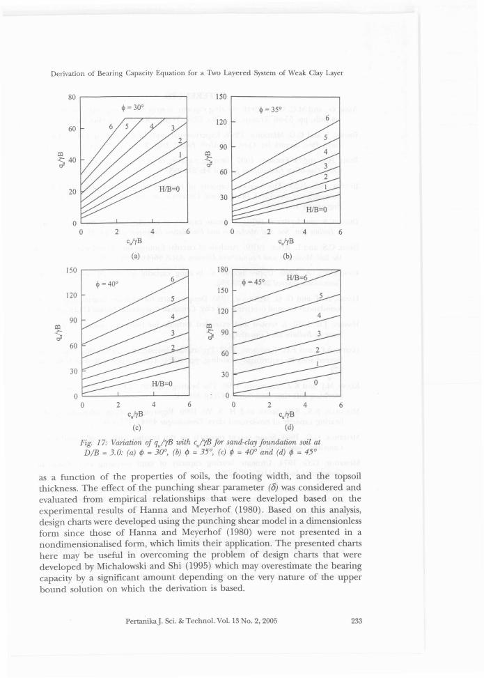
Fig. 17: Variation of qJrB with cJrB fOT sand-clay foundation soil atDIB = 3.0: (a) ¢ = 30°, (b) ¢ = 35°, (c) ¢ = 40° and (d) ¢ = 45°
as a function of the properties of soils, the footing width, and the topsoilthickness. The effect of the punching shear parameter (0) was considered andevaluated from empirical relationships that were developed based on theexperimental results of Hanna and Meyerhof (1980). Based on this analysis,design charts were developed using the punching shear model in a dimensionlessform since those of Hanna and Meyerhof (1980) were not presented in anondimensionalised form, which limits their application. The presented chartshere may be useful in overcoming the problem of design charts that weredeveloped by Michalowski and Shi (1995) which may overestimate the bearingcapacity by a significant amount depending on the very nature of the upperbound solution on which the derivation is based.
PertanikaJ. Sci. & Techno!. Vo!. 13 0.2,2005 233
Abdulhafiz O. Al-Shenawy & Awad A. Al-Karni
REFERENCESAzAM, G., and M.C. WANG. 1991. Bearing capacity of strip footing supported by two-layer
c~ soils. pp. 55-66. Transp. Res. o. 1331, Transp. Res. Board, Washington, D. C.
BROWN, J. and G.G. MEYERHOF. 1969. Experimental study of bearing capacity in layeredclays. Proc. Stmenth Int. Con! Soil Mech. Found. Eng., 2: 45-51. Mexico City, Mexico.
BURD, HJ. and S. FRIDMAN. 1997. Bearing capacity of plane-strain footings on layeredsoils. Canadian Geotechnical journal 34: 241-253.
BlJITON, S.S. 1953. The bearing capacity of footings on two-layer cohesive subsoil.Proceedings of the Third International Conference on Soil Mechanics and FoundationEngineering 1: 332-335.
DESAI, C.S. and L. REESE. 1970a. Ultimate capacity of circular footings on layered soils.J Indian Nat. Soc. Soil Mechanics and Foundation Engineering 96(1): 41-50.
DESAI, C.S. and L. REESE. 1970b. Analysis of circular footings on layered soils. journal ofthe Soil Mechanics and Foundations Division ASCE 96(4): 1289-1310.
FLORKIEWICZ, A. 1989. Upper bound to bearing capacity of layered soils. CanadianGeotechnical journal 26(4): 730-736.
HANNA, A.M. and G. G. MEYERHOF. 1980. Design charts for ultimate bearing capacity offoundations on sand overlying soft clay. Canadian GeotechnicaljournalI7(2): 300-303.
HANSEN, J.B. 1970. A revised and extended formula for bearing capacity. GeotechnicalInstitute Bul!£tin 28: Copenhagen.
HARDY, A.C. and F.C. TOWNSEND. 1982. Preliminary investigation of bearing capacity oflayered soils by centrifugal modeling, pp. 20-24. Transportation Research Record872.
•KENNY, MJ. and K.Z. ANDRAWES. 1996. The bearing capacity of footings on a sand layer
overlying soft clay. Geotechnique 47(2): 339-345.
MERlFlELD, R.S., S.W. SLOAN and H. S. Yu. 1999. Rigorous plasticity solutions for thebearing capacity of two-layered clays. Geotechnique 49(4): 471-490.
MEYERHOF, G.G. 1963. Some recent research on the bearing capacity of foundations.Canadian Geotechnical journal 1(1): 16-26.
MEYERHOF, G.G. 1974. Ultimate bearing capacity of sand overlying clay. CanadianGeotechnical journal 11 (2): 224-229.
MEYERHOF, G.G. and A.M. HANNA. 1978. Ultimate bearing capacity of foundations onlayered soil under inclined load. Canadian Geotechnical journal 15(4): 565-572.
MICHALOWSRl, R.L. and L. SHI. 1995. Bearing capacity offootings over two-layer foundationsoils. journal of Geotechnical Engineering ASCE 121(5): 421-428.
OKAMURA, M., J. TAKEMURA and T. KIMURA. 1997. Centrifuge model tests bearing capacityand deformation of sand layer overlying clay. Soils and Foundations 37(1): 73-88.
PRANDTL, L. 1921. Uber die Eindringungsfestigkeit plastisher Baustoffe und die Festigkeitvon Schneiden.i Zeitschrift fur Angewandte Mathematik und Mechanik 1(1): 15-20.
234 PerIanikaJ. Sci. & Technol. Vol. 13 0.2,2005
Derivation of Bearing Capacity Equation for a Two Layered System of Weak Clay Layer
PURUSHOTHAMARAJ, P., B.K. RAM1AH and K.N. Y.RAo. 1974. Bearing capacity of strip footingin two layered cohesive-friction soils. Canadian Geotechnical Journal 11: 32-45.
REISS ER, H. 1924. Zum Erddruckproblem. Proceedings, Frist International Conference onApplied Mechanics, pp. 295-311. Delft.
SAITANARAYANA, A.M. and R.K. CARG. 1980. Bearing capacity offootings on layered C1> soils.Journal of Geotechnical Engineering Division ASCE 106 Gt7: 819-824.
SIVAREDDY, A. and R. J. SRINIVASAN. 1967. Bearing capacity of footings on layered clays.Proceedings ASCE, Journal of the Soil Mechanics and Foundations Division 938M2: 83-99.
TERZAGHI, K. 1943. Theoretical Soil Mechanics. ew York: J. Wiley & Sons.
VESIC, A. S. 1973. Analysis of ultimate loads of Shallow foundations. Journal of the SoilMechanics and Foundations Division, ASCE 99 8Ml: 45-73.
PertanikaJ. Sci. & Techno!. Vo!. 13 No.2, 2005 235