Embed Size (px)
Citation preview
Descent Assisted Split Habitat Lunar Lander Concept
Daniel D. Mazanek and Kandyce E. Goodliff National Aeronautics and Space Administration (NASA) Langley Research Center
MS 462 Hampton, VA 23681
757-864-1739 / 757-864-4969 [email protected] / [email protected]
David M. Cornelius
Analytical Mechanics Associates, Inc. 303 Butler Farm Road, Suite 104A
Hampton, VA 23666 757-865-0944
Abstract—The Descent Assisted Split Habitat (DASH) lunar lander concept utilizes a disposable braking stage for descent and a minimally sized pressurized volume for crew transport to and from the lunar surface. The lander can also be configured to perform autonomous cargo missions. Although a braking-stage approach represents a significantly different operational concept compared with a traditional two-stage lander, the DASH lander offers many important benefits. These benefits include improved crew egress/ingress and large-cargo unloading; excellent surface visibility during landing; elimination of the need for deep-throttling descent engines; potentially reduced plume-surface interactions and lower vertical touchdown velocity; and reduced lander gross mass through efficient mass staging and volume segmentation. This paper documents the conceptual study on various aspects of the design, including development of sortie and outpost lander configurations and a mission concept of operations; the initial descent trajectory design; the initial spacecraft sizing estimates and subsystem design; and the identification of technology needs.1 2
TABLE OF CONTENTS
1. INTRODUCTION................................................................ 1 2. DASH LANDER OVERVIEW AND DESIGN APPROACH.... 2 3. DESCENT TRAJECTORY DESIGN ..................................... 3 4. SORTIE LANDER DESIGN................................................. 5 5. DASH LANDER DESIGNS FOR OUTPOST SUPPORT ...... 14 6. DESIGN CHALLENGES & RISKS, TECHNOLOGY NEEDS,
AND FUTURE WORK ...................................................... 15 7. CONCLUSIONS ............................................................... 15 REFERENCES ..................................................................... 15 BIOGRAPHY ....................................................................... 16 ACKNOWLEDGEMENTS ..................................................... 16
1 1 IEEEAC paper #1384, Version 15, Updated February 21, 2008 2 U.S. Government work not protected by U.S. copyright.
1. INTRODUCTION
In support of NASA’s Vision for Space Exploration, a Lunar Lander Preparatory Study (LLPS) was conducted as part of NASA’s Lunar Lander Pre-Project in 2006 to explore a wide breadth of conceptual lunar lander designs. Teams from nearly every NASA field center responded, providing dozens of innovative designs that addressed one or more specific lander technical challenges. Although none of the conceptual lander designs sought to solve every technical design issue, each added significantly to the technical database available to the Lunar Lander Project Office as it began operations in 2007. A team of engineers at the Langley Research Center conceived of and designed the Descent Assisted Split Habitat (DASH) lander concept. The DASH lander described in this paper represents a “pre-Phase A” study effort to determine the top-level feasibility of this lander approach. Limited resources were provided to develop this lander concept during the LLPS. More detailed design efforts would be required to fully evaluate the performance and risk of this conceptual design. During the LLPS, the DASH lander team was directed to focus their study efforts on refining specific aspects of the design by investigating a minimal ascent stage habitat design, refining the trajectory velocity change requirements, and identifying the primary issues associated with vehicle staging during descent. An initial risk analysis was conducted for all designs by a separate LLPS team. This risk analysis focused on propulsion system design comparative risk between the LLPS concepts and a two stage, single habitat lander design baselined during the Exploration Systems Architecture Study (ESAS) [1]. This paper qualitatively addresses relative risk between DASH lander and the baseline lander, but is not supported by a rigorous risk analysis and does not document the limited risk analysis performed during LLPS by the risk assessment team.
1
https://ntrs.nasa.gov/search.jsp?R=20080013516 2019-02-28T19:17:15+00:00Z
2. DASH LANDER OVERVIEW AND DESIGN APPROACH
The DASH lander is a versatile human and cargo lander concept that utilizes a disposable braking stage for lunar descent and a minimally sized habitat for crew transport to and from the lunar surface. The design approach for the DASH lander was to investigate a vertical lander concept that could significantly simplify surface operations by facilitating crew access and large-cargo deployment while reducing lander mass for both sortie and outpost missions. Past lunar mission approaches like the proposed Apollo direct flight modes included the use of a lunar braking module [2], and the Russian LK ('Lunniy Korabl' - lunar craft) lander included the use of a “crasher stage” during descent to the lunar surface [3, 4]. These innovative approaches for landing humans on the Moon, combined with the desire to get the crew and cargo extremely close to the lunar surface, provided the inspiration for the DASH lander.
Main Features and Benefits
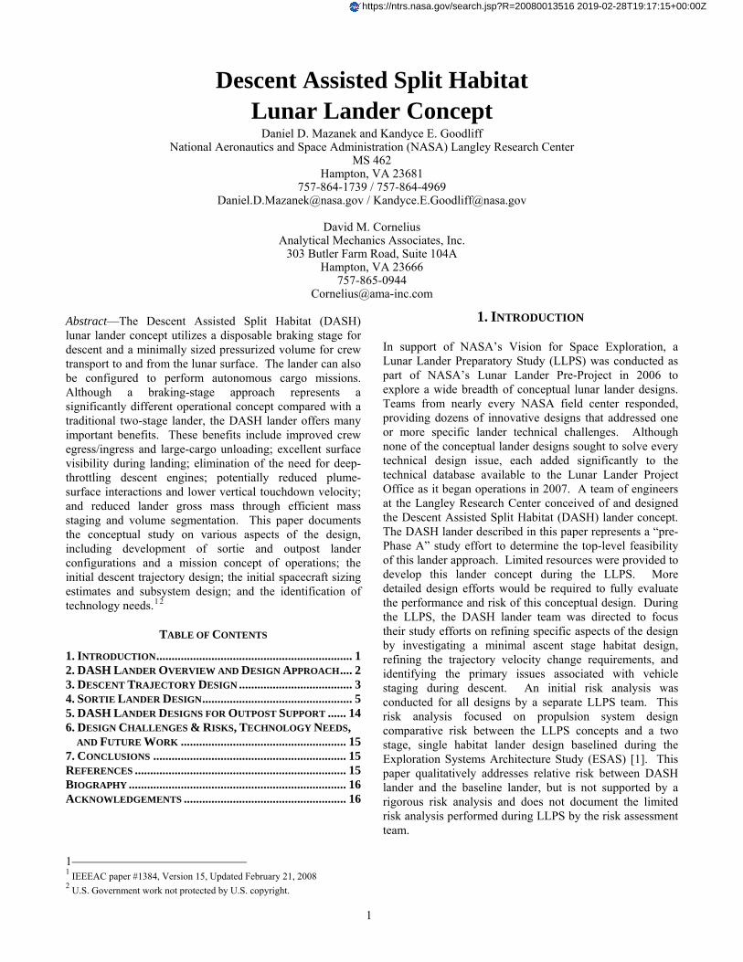
The DASH lander consists of three modules, as shown in Figure 1. The first module, the Lander Module (LM), provides all critical lander subsystems (propulsion, avionics, hazard avoidance, etc.) and utilizes a high-reliability pressure-fed hypergolic propulsion system with two engines that are derived from the Space Shuttle orbital maneuvering engine (OME) for final descent and ascent [5]. The height of the engines from the surface is approximately 3.7 m (12.1 ft), which reduces surface plume debris and should permit lower vertical touchdown velocity. The Transport Habitat, a part of the Lander Module, is an innovative, gem-shaped biconic habitat that provides efficient volume and excellent visibility for the crew during descent and ascent. The Transport Habitat can also be used during surface operations as separate sleeping quarters or for crew privacy.
The second module, the Payload Module (PM), provides a versatile platform that can accommodate both pressurized and unpressurized surface payloads, specifically lunar surface habitats, outpost infrastructure and cargo, and other surface equipment. The Surface Habitat consists of a rigid central core module with both an inflatable airlock and an alcove located on the front and rear of the lander, respectively, or a single, larger inflatable volume at the rear. Inflatables for expanded surface habitat volume permit tailoring of the pressurized volume for mission needs while still providing excellent pilot visibility during descent. The DASH concept can also support the use of suitport or suitlock approaches for Extra-Vehicular Activity (EVA), with the surface suits either attached externally during descent or contained within the rigid central core and mated externally after the initial lunar excursion.
Figure 1 – DASH lander modules
Lander Module
Payload Module
Retro Module
Transport Habitat
Surface Habitat
Lander Module
Payload Module
Retro Module
Transport Habitat
Surface Habitat
The third module, the Retro Module (RM), is a high-performance in-space braking stage powered by a pump-fed liquid oxygen/liquid hydrogen (LOX/LH2) propulsion system with a single RL10B-2 engine. The Retro Module engine is not required to throttle because the Lander Module engines perform the final portion of descent and landing. The RL10B-2 is a mature, in-space engine with significant heritage [6]. Its use for the DASH lander concept should require little to no modification, unlike the deep-throttling required if used for terminal descent. Twin RL10B-2 engines can be accommodated if including an extra engine significantly reduces mission risk [5].
DASH Lander Concept of Operations
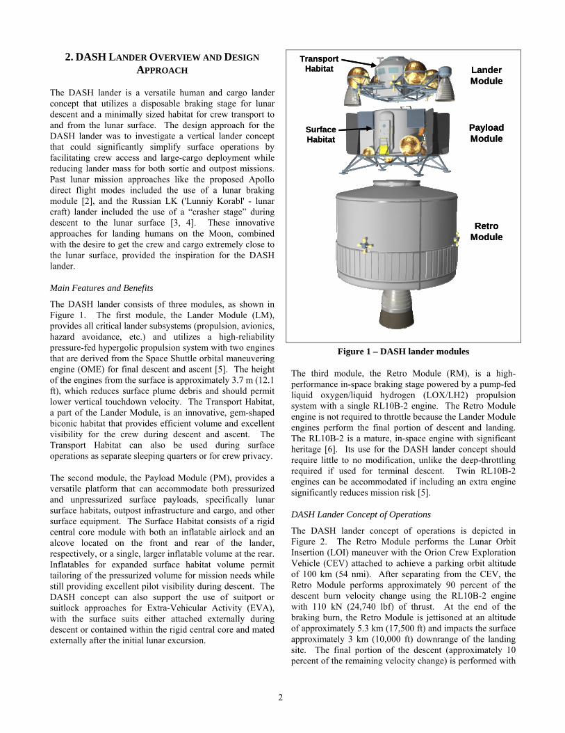
The DASH lander concept of operations is depicted in Figure 2. The Retro Module performs the Lunar Orbit Insertion (LOI) maneuver with the Orion Crew Exploration Vehicle (CEV) attached to achieve a parking orbit altitude of 100 km (54 nmi). After separating from the CEV, the Retro Module performs approximately 90 percent of the descent burn velocity change using the RL10B-2 engine with 110 kN (24,740 lbf) of thrust. At the end of the braking burn, the Retro Module is jettisoned at an altitude of approximately 5.3 km (17,500 ft) and impacts the surface approximately 3 km (10,000 ft) downrange of the landing site. The final portion of the descent (approximately 10 percent of the remaining velocity change) is performed with
2
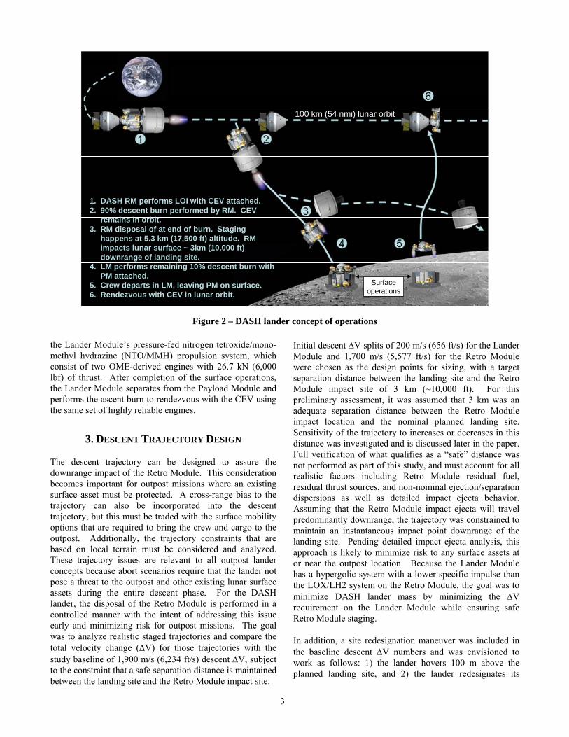
Figure 2 – DASH lander concept of operations
100 km (54 nmi) lunar orbit
Surface operations
1. DASH RM performs LOI with CEV attached.2. 90% descent burn performed by RM. CEV
remains in orbit.3. RM disposal of at end of burn. Staging
happens at 5.3 km (17,500 ft) altitude. RM impacts lunar surface ~ 3km (10,000 ft) downrange of landing site.
4. LM performs remaining 10% descent burn with PM attached.
5. Crew departs in LM, leaving PM on surface.6. Rendezvous with CEV in lunar orbit.
the Lander Module’s pressure-fed nitrogen tetroxide/mono-methyl hydrazine (NTO/MMH) propulsion system, which consist of two OME-derived engines with 26.7 kN (6,000 lbf) of thrust. After completion of the surface operations, the Lander Module separates from the Payload Module and performs the ascent burn to rendezvous with the CEV using the same set of highly reliable engines.
3. DESCENT TRAJECTORY DESIGN
The descent trajectory can be designed to assure the downrange impact of the Retro Module. This consideration becomes important for outpost missions where an existing surface asset must be protected. A cross-range bias to the trajectory can also be incorporated into the descent trajectory, but this must be traded with the surface mobility options that are required to bring the crew and cargo to the outpost. Additionally, the trajectory constraints that are based on local terrain must be considered and analyzed. These trajectory issues are relevant to all outpost lander concepts because abort scenarios require that the lander not pose a threat to the outpost and other existing lunar surface assets during the entire descent phase. For the DASH lander, the disposal of the Retro Module is performed in a controlled manner with the intent of addressing this issue early and minimizing risk for outpost missions. The goal was to analyze realistic staged trajectories and compare the total velocity change (ΔV) for those trajectories with the study baseline of 1,900 m/s (6,234 ft/s) descent ΔV, subject to the constraint that a safe separation distance is maintained between the landing site and the Retro Module impact site.
Initial descent ΔV splits of 200 m/s (656 ft/s) for the Lander Module and 1,700 m/s (5,577 ft/s) for the Retro Module were chosen as the design points for sizing, with a target separation distance between the landing site and the Retro Module impact site of 3 km (~10,000 ft). For this preliminary assessment, it was assumed that 3 km was an adequate separation distance between the Retro Module impact location and the nominal planned landing site. Sensitivity of the trajectory to increases or decreases in this distance was investigated and is discussed later in the paper. Full verification of what qualifies as a “safe” distance was not performed as part of this study, and must account for all realistic factors including Retro Module residual fuel, residual thrust sources, and non-nominal ejection/separation dispersions as well as detailed impact ejecta behavior. Assuming that the Retro Module impact ejecta will travel predominantly downrange, the trajectory was constrained to maintain an instantaneous impact point downrange of the landing site. Pending detailed impact ejecta analysis, this approach is likely to minimize risk to any surface assets at or near the outpost location. Because the Lander Module has a hypergolic system with a lower specific impulse than the LOX/LH2 system on the Retro Module, the goal was to minimize DASH lander mass by minimizing the ΔV requirement on the Lander Module while ensuring safe Retro Module staging.
In addition, a site redesignation maneuver was included in the baseline descent ΔV numbers and was envisioned to work as follows: 1) the lander hovers 100 m above the planned landing site, and 2) the lander redesignates its
3
landing location to within 50 m (164 ft) of the planned site to accommodate surface hazard avoidance. This redesignation area was initially assumed to be circular, as shown in Figure 3(a); however, it quickly became apparent that landers typically have low but non-zero horizontal velocity late in flight and that a redesignation area that does not require the lander to completely stop and reverse direction could be more efficient. Also, visibility and identification of hazards in the direction of motion may be much better than that behind the lander’s current location, assuming human pilot in the loop and the use of a window for visibility. Therefore, analysis was performed on an equivalent area that was wedge shaped with the nominal landing site at the apex of the wedge, as shown in Figure 3(b). Analysis confirmed that this wedge-shaped redesignation area saved approximately 4.5 m/s (14.8 ft/s) over the circular area; thus, this area was adopted as the baseline for trajectory analyses. An additional 4.5 m/s (14.8 ft/s) can be saved if the 50 m site redesignation distance is maintained, but only in the forward direction.
Figure 3 – Comparison of landing site redesignation footprints
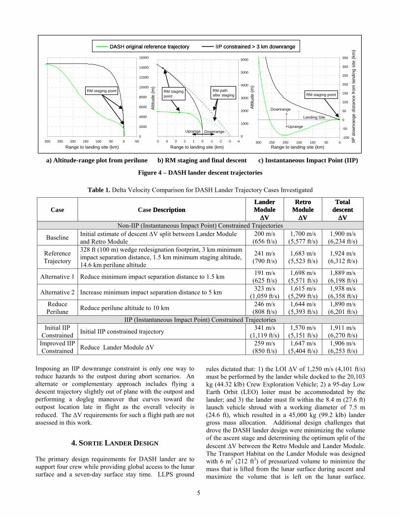
The original reference trajectory is represented by the green curves in Figures 4(a) and 4(b). The altitude-range plot shows the trajectory from the perilune altitude of approximately 15 km (8 nmi) to the lunar surface but does not show the burn that is necessary to reduce the circular parking orbit from 100 km (54 nmi) to 100 × 15 km. The Retro Module burns continuously from near perilune to just before the staging point at approximately 2 km (6,100 ft) in altitude and 3 km uprange of the landing site. At staging, the Retro Module thrust has terminated and follows a ballistic trajectory to its impact point more than 3 km downrange of the landing site. Results for this reference trajectory agreed well with the baseline ΔVs, resulting in a total of 1,924 m/s (6,312 ft/s). Additionally, trajectories with varied separation distances between the landing site and the impact point and with a reduced perilune altitude were analyzed; results are shown in Table 1. Total descent
ΔV for these cases ranged from 1,889 m/s (6,198 ft/s) to 1,938 m/s (6,358 ft/s), depending on constraints.
One observation from the trajectory analysis was the movement of the instantaneous impact point (IIP) with trajectory design. The IIP is the point on the lunar surface that the vehicle or object would strike at each point in time if all thrusting were terminated and the object followed a ballistic path from the current state (position and velocity). The IIP can also be thought of as the map of nominal impact points for “dropped” portions of the vehicle during an abort situation. This type of IIP was not initially a concern because sortie mission designs were the initial LLPS focus and this same IIP behavior is also seen in the Apollo trajectories. However, when considering an outpost mission, IIP migration uprange of the landing site is a significant concern for all lander designs. Early in the trajectory, when the IIP crosses the landing site/outpost and moves uprange, the lander is still traveling with a significant portion of its orbital speed, and the descent stage or Retro Module is nearly full of propellant. An abort during this phase, even if the IIP is significantly uprange of the outpost, would have to consider risk to the outpost from the high impact energy, explosive propellants, low flight-path angle, trajectory error ellipse, and range/velocity of impact ejecta from the impact event. Many of these risks can be eliminated or reduced significantly by keeping the IIP downrange of the outpost at all times.
Radius = 50 m
Arc Angle = 90°
X
Area = (7,854 m2)
Approachdirection
Approachdirection
100 m50 m
Area = 1,964 m2Nominal site Nominal site
(a) Original circular (b) Revised wedge
Area = (7,854 m2)
Saves ~9 m/s
Saves ~4.5 m/s(baseline)
X
Radius = 50 m
Arc Angle = 90°
X
Area = (7,854 m2)
Approachdirection
Approachdirection
100 m50 m
Area = 1,964 m2Nominal site Nominal site
(a) Original circular (b) Revised wedge
Area = (7,854 m2)
Saves ~9 m/s
Saves ~4.5 m/s(baseline)
X
The IIP position on the lunar surface relative to the planned landing site for the original DASH lander reference trajectory is shown by the green curve in Figure 4(c). Note that the IIP starts out far downrange of the landing site. As the range to the landing site decreases, the IIP migrates past the landing site to as much as 80 km (43 nmi) uprange of the landing site before migrating downrange, crossing again when the lander is about 25 km (13.5 nmi) from touchdown. At the time of Retro Module staging, the IIP downrange value is 3.1 km (~10,200 ft), which corresponds to the actual downrange impact site of the Retro Module, as shown in Figure 4(b). The black curves in Figure 4(a), 4(b) and 4(c) show a new trajectory that constrains the IIP downrange of the landing site. This trajectory maintains altitude much longer and includes a much more vertical approach to the landing site. In addition, the staging altitude is pushed above 5.3 km (17,500 ft), as compared with the reference trajectory staging altitude of approximately 2 km (6,100 ft). The total ΔV for the IIP constrained trajectory as shown in Table 1 is 1,911 m/s (6,270 ft/s). An improved IIP trajectory that is more optimized to keep the ΔV for the Lander Module low is also defined resulting in a reduced Lander Module ΔV from 341 m/s (1,119 ft/s) to 259 m/s (850 ft/s).
4
DASH original reference trajectory IIP constrained > 3 km downrangeDASH original reference trajectory IIP constrained > 3 km downrange
0
2000
4000
6000
8000
10000
12000
14000
16000
-50050100150200250300
Alti
tude
(m)
Range to landing site (km)
-100
-50
0
50
100
150
200
250
300
350
050100150200250300Range to Landing Site (km)
IIP D
ownr
ange
Dis
tanc
e fr
om L
andi
ng S
ite (k
m)
Landing Site
IIP d
ownr
ange
dis
tanc
e fro
m la
ndin
g si
te (k
m)
0
1000
2000
3000
4000
5000
6000
-4-3-2-1012345Range to Landing Site (km)
Alti
tude
(m)
Uprange
Downrange
Uprange Downrange
RM staging point RM stagingpoint RM staging point
RM pathafter staging
Range to landing site (km) Range to landing site (km)
Uprange DownrangeUprange
Downrange
Landing Site
Altit
ude
(m)
Altit
ude
(m)
a) Altitude-range plot from perilune b) RM staging and final descent c) Instantaneous Impact Point (IIP)
Figure 4 – DASH lander descent trajectories
Table 1. Delta Velocity Comparison for DASH Lander Trajectory Cases Investigated
Case Case Description Description Lander Module ΔV
Lander Module ΔV
Retro Module ΔV
Retro Module ΔV
Total descent ΔV
Total descent ΔV
Non-IIP (Instantaneous Impact Point) Constrained Trajectories
Baseline Initial estimate of descent ΔV split between Lander Module and Retro Module
200 m/s (656 ft/s)
1,700 m/s (5,577 ft/s)
1,900 m/s (6,234 ft/s)
Reference Trajectory
328 ft (100 m) wedge redesignation footprint, 3 km minimum impact separation distance, 1.5 km minimum staging altitude, 14.6 km perilune altitude
241 m/s (790 ft/s)
1,683 m/s (5,523 ft/s)
1,924 m/s (6,312 ft/s)
Alternative 1 Reduce minimum impact separation distance to 1.5 km 191 m/s (625 ft/s)
1,698 m/s (5,571 ft/s)
1,889 m/s (6,198 ft/s)
Alternative 2 Increase minimum impact separation distance to 5 km 323 m/s (1,059 ft/s)
1,615 m/s (5,299 ft/s)
1,938 m/s (6,358 ft/s)
Reduce Perilune Reduce perilune altitude to 10 km 246 m/s
(808 ft/s) 1,644 m/s
(5,393 ft/s) 1,890 m/s
(6,201 ft/s) IIP (Instantaneous Impact Point) Constrained Trajectories
Initial IIP Constrained Initial IIP constrained trajectory 341 m/s
(1,119 ft/s) 1,570 m/s
(5,151 ft/s) 1,911 m/s
(6,270 ft/s) Improved IIP Constrained Reduce Lander Module ΔV 259 m/s
(850 ft/s) 1,647 m/s
(5,404 ft/s) 1,906 m/s
(6,253 ft/s) Imposing an IIP downrange constraint is only one way to reduce hazards to the outpost during abort scenarios. An alternate or complementary approach includes flying a descent trajectory slightly out of plane with the outpost and performing a dogleg maneuver that curves toward the outpost location late in flight as the overall velocity is reduced. The ΔV requirements for such a flight path are not assessed in this work.
4. SORTIE LANDER DESIGN
The primary design requirements for DASH lander are to support four crew while providing global access to the lunar surface and a seven-day surface stay time. LLPS ground
rules dictated that: 1) the LOI ΔV of 1,250 m/s (4,101 ft/s) must be performed by the lander while docked to the 20,103 kg (44.32 klb) Crew Exploration Vehicle; 2) a 95-day Low Earth Orbit (LEO) loiter must be accommodated by the lander; and 3) the lander must fit within the 8.4 m (27.6 ft) launch vehicle shroud with a working diameter of 7.5 m (24.6 ft), which resulted in a 45,000 kg (99.2 klb) lander gross mass allocation. Additional design challenges that drove the DASH lander design were minimizing the volume of the ascent stage and determining the optimum split of the descent ΔV between the Retro Module and Lander Module. The Transport Habitat on the Lander Module was designed with 6 m3 (212 ft3) of pressurized volume to minimize the mass that is lifted from the lunar surface during ascent and maximize the volume that is left on the lunar surface.
5
While on the surface, the Surface Habitat on the Payload Module contains the primary pressurized volume and provides most of the power and life support functions during the surface stay. This volume is split between a 14-m3 (494-ft3) rigid volume and two 6-m3 (212-ft3) inflatable volumes. One volume serves as the airlock, and the other serves as an alcove. This volume could also be configured to be a single, larger pressurized volume (either inflatable or rigid).
Mass Estimate
The mass of the Lander Module and the Payload Module were sized using EXAMINE (EXploration Architecture Model for IN-space and Earth-to-orbit), a NASA-developed sizing tool that combines performance with subsystem sizing based on historical mass-estimating relationships. EXAMINE has been validated by sizing Apollo spacecraft. It has also been used to size multiple lander configurations with the results compared to those from sizing algorithms used at other NASA Centers. The Retro Module was sized using SPSP (Space Propulsion Sizing Program), a software tool developed at NASA Langley Research Center. SPSP mass estimates were validated by using the tool to estimate subsystem masses of existing upper stages. These tools provide a conceptual level sizing capability, but their absolute accuracy is difficult to assess because of the limited number of validation points available, which are also often used to develop the sizing algorithms themselves. Additionally, these tools are generally used to develop estimates for spacecraft that are inherently different from spacecraft used for validation. Design margin was included in the mass estimates to account for uncertainties in the sizing algorithms. As dictated by the LLPS requirements, the Lander Module and Payload Module include 20% dry mass growth. However, 15% dry mass growth was used for the Retro Module due to the similarity to mature in-space propulsion stages. These mass growth allowances are included to account for modeling uncertainties, programmatic growth due to requirements creep, ΔV
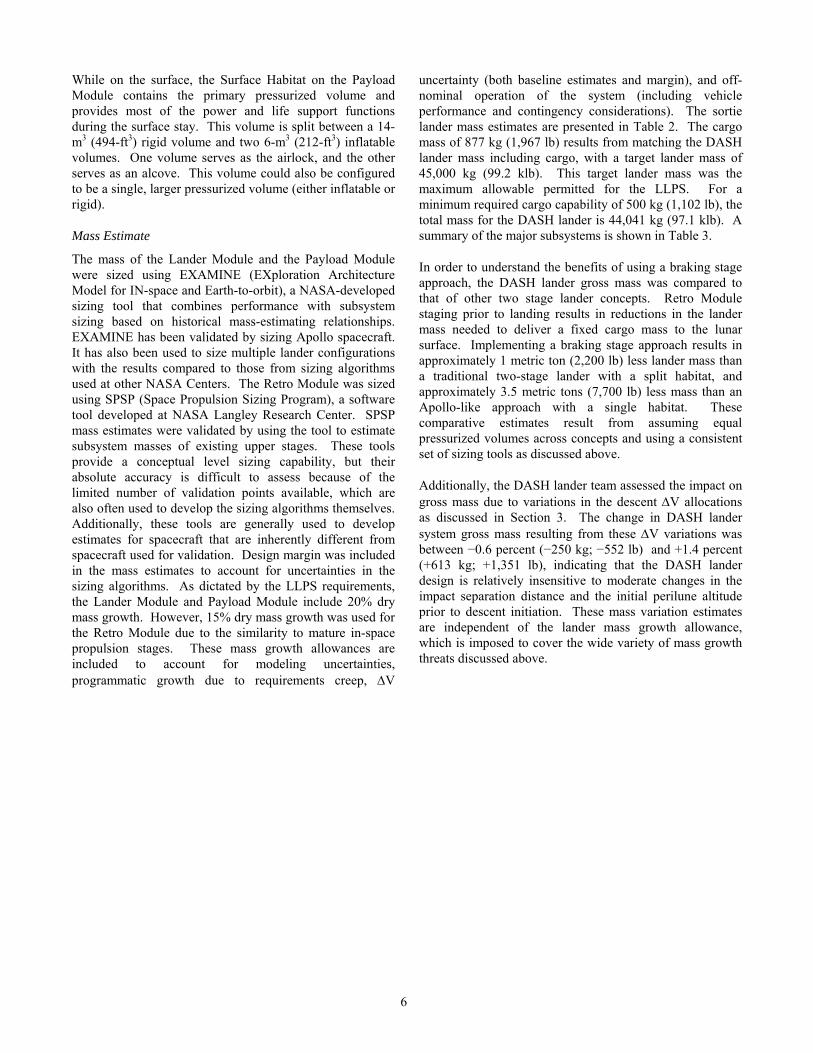
uncertainty (both baseline estimates and margin), and off-nominal operation of the system (including vehicle performance and contingency considerations). The sortie lander mass estimates are presented in Table 2. The cargo mass of 877 kg (1,967 lb) results from matching the DASH lander mass including cargo, with a target lander mass of 45,000 kg (99.2 klb). This target lander mass was the maximum allowable permitted for the LLPS. For a minimum required cargo capability of 500 kg (1,102 lb), the total mass for the DASH lander is 44,041 kg (97.1 klb). A summary of the major subsystems is shown in Table 3.
In order to understand the benefits of using a braking stage approach, the DASH lander gross mass was compared to that of other two stage lander concepts. Retro Module staging prior to landing results in reductions in the lander mass needed to deliver a fixed cargo mass to the lunar surface. Implementing a braking stage approach results in approximately 1 metric ton (2,200 lb) less lander mass than a traditional two-stage lander with a split habitat, and approximately 3.5 metric tons (7,700 lb) less mass than an Apollo-like approach with a single habitat. These comparative estimates result from assuming equal pressurized volumes across concepts and using a consistent set of sizing tools as discussed above.
Additionally, the DASH lander team assessed the impact on gross mass due to variations in the descent ΔV allocations as discussed in Section 3. The change in DASH lander system gross mass resulting from these ΔV variations was between −0.6 percent (−250 kg; −552 lb) and +1.4 percent (+613 kg; +1,351 lb), indicating that the DASH lander design is relatively insensitive to moderate changes in the impact separation distance and the initial perilune altitude prior to descent initiation. These mass variation estimates are independent of the lander mass growth allowance, which is imposed to cover the wide variety of mass growth threats discussed above.
6
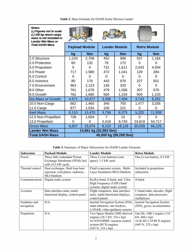
Table 2. Mass Estimate for DASH Sortie Mission Lander
kg lbm kg lbm kg lbm1.0 Structure 1,229 2,709 452 996 537 1,1842.0 Protection 60 132 78 172 0 03.0 Propulsion 0 0 731 1,611 2,043 4,5044.0 Power 717 1,580 472 1,041 129 2845.0 Control 0 0 0 0 0 06.0 Avionics 80 176 443 976 227 5017.0 Environment 963 2,123 145 320 0 08.0 Other 761 1,678 479 1,056 307 6769.0 Growth 762 1,680 560 1,234 500 1,103Dry Mass w/ Growth 4,571 10,077 3,358 7,404 3,743 8,25210.0 Non-Cargo 662 1,460 340 750 1,477 3,25611.0 Cargo 877 1,934 100 221 0 0Inert Mass 6,110 13,470 3,799 8,375 5,220 11,50812.0 Non-Propellant 728 1,604 7 15 0 013.0 Propellant 0 0 4,418 9,740 24,819 54,717Gross Mass 6,837 15,074 8,223 18,129 30,039 66,225Lander Wet MassTotal DASH Mass 45,000 kg (99,208 lbm)
Payload Module Lander Module
14,961 kg (32,983 lbm)
Retro Module
Notes:1.) Figures not to scale2.) 100 kg return cargo mass is not included in Lander Wet Mass or Total DASH Mass
Table 3. Summary of Major Subsystems for DASH Lander Elements
Subsystem Payload Module Lander Module Retro Module Power Three fully redundant Proton
Exchange Membrane (PEM) fuel cells (4.5 kW each)
Three Li-ion batteries (one spare), 1.5 kW each
One Li-ion battery, 0.5 kW
Thermal control Heat exchanger, fluid loop heat rejection, cold plates, radiators, MLI blankets
Fluid evaporator system, Multi-Layer Insulation (MLI) blankets
Included in propulsion subsystem
Communications Digital audio system Ka/Ku-band, S-band, and Ultra High Frequency (UHF) band systems, digital audio system
S-band
Avionics Data interface units, multi-functional display, control panel
Flight computers, data interface units, multi-functional displays, control panels
C-band radar, decoder, flight computer, data processor, multiplexer
Guidance and navigation
N/A Inertial Navigation System (INS), radar altimeter, star trackers, LADAR, video guidance sensors
Inertial Navigation System (INS), gyros, accelerometer
Propulsion N/A Two Space Shuttle OME-derived engines (26.7 kN, 316 s Isp) 16-NTO/MMH reaction control system (RCS) engines (445 N, 316 s Isp)
One RL-10B-2 engine (110 kN, 460 s Isp) 16-R-4D-1/10 RCS engines (445 N, 325 s Isp)
7
Lunar Surface Configuration
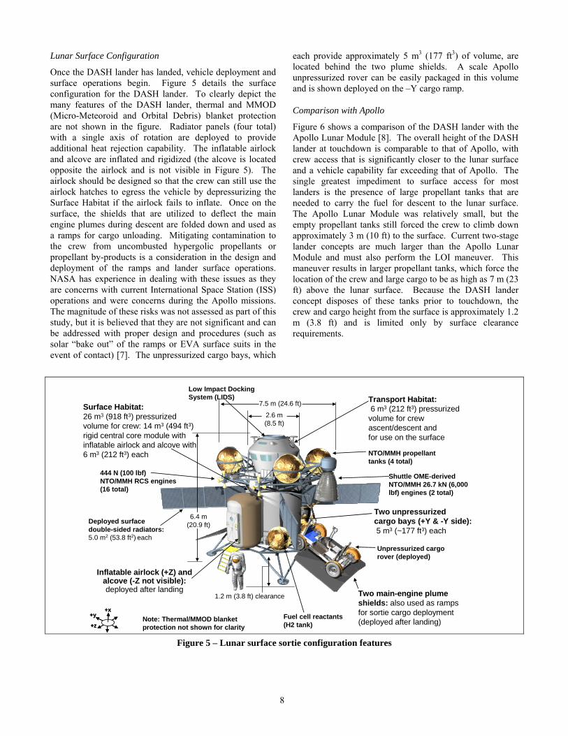
Once the DASH lander has landed, vehicle deployment and surface operations begin. Figure 5 details the surface configuration for the DASH lander. To clearly depict the many features of the DASH lander, thermal and MMOD (Micro-Meteoroid and Orbital Debris) blanket protection are not shown in the figure. Radiator panels (four total) with a single axis of rotation are deployed to provide additional heat rejection capability. The inflatable airlock and alcove are inflated and rigidized (the alcove is located opposite the airlock and is not visible in Figure 5). The airlock should be designed so that the crew can still use the airlock hatches to egress the vehicle by depressurizing the Surface Habitat if the airlock fails to inflate. Once on the surface, the shields that are utilized to deflect the main engine plumes during descent are folded down and used as a ramps for cargo unloading. Mitigating contamination to the crew from uncombusted hypergolic propellants or propellant by-products is a consideration in the design and deployment of the ramps and lander surface operations. NASA has experience in dealing with these issues as they are concerns with current International Space Station (ISS) operations and were concerns during the Apollo missions. The magnitude of these risks was not assessed as part of this study, but it is believed that they are not significant and can be addressed with proper design and procedures (such as solar “bake out” of the ramps or EVA surface suits in the event of contact) [7]. The unpressurized cargo bays, which
each provide approximately 5 m3 (177 ft3) of volume, are located behind the two plume shields. A scale Apollo unpressurized rover can be easily packaged in this volume and is shown deployed on the –Y cargo ramp.
Comparison with Apollo
Figure 6 shows a comparison of the DASH lander with the Apollo Lunar Module [8]. The overall height of the DASH lander at touchdown is comparable to that of Apollo, with crew access that is significantly closer to the lunar surface and a vehicle capability far exceeding that of Apollo. The single greatest impediment to surface access for most landers is the presence of large propellant tanks that are needed to carry the fuel for descent to the lunar surface. The Apollo Lunar Module was relatively small, but the empty propellant tanks still forced the crew to climb down approximately 3 m (10 ft) to the surface. Current two-stage lander concepts are much larger than the Apollo Lunar Module and must also perform the LOI maneuver. This maneuver results in larger propellant tanks, which force the location of the crew and large cargo to be as high as 7 m (23 ft) above the lunar surface. Because the DASH lander concept disposes of these tanks prior to touchdown, the crew and cargo height from the surface is approximately 1.2 m (3.8 ft) and is limited only by surface clearance requirements.
Figure 5 – Lunar surface sortie configuration features
2.6 m(8.5 ft)
Transport Habitat:6 m3 (212 ft3) pressurized
volume for crew ascent/descent andfor use on the surface
Surface Habitat:26 m3 (918 ft3) pressurized volume for crew: 14 m3 (494 ft3) rigid central core module with inflatable airlock and alcove with 6 m3 (212 ft3) each
6.4 m (20.9 ft)
1.2 m (3.8 ft) clearance
7.5 m (24.6 ft)
Two unpressurizedcargo bays (+Y & -Y side):5 m3 (~177 ft3) each
+x
+z
+y+x
+z
+y
Inflatable airlock (+Z) and alcove (-Z not visible): deployed after landing Two main-engine plume
shields: also used as ramps for sortie cargo deployment (deployed after landing)
Deployed surface double-sided radiators: 5.0 m2 (53.8 ft2) each
Unpressurized cargo rover (deployed)
Shuttle OME-derived NTO/MMH 26.7 kN (6,000 lbf) engines (2 total)
444 N (100 lbf) NTO/MMH RCS engines (16 total)
NTO/MMH propellant tanks (4 total)
Fuel cell reactants (H2 tank)
Low Impact Docking System (LIDS)
Note: Thermal/MMOD blanket protection not shown for clarity
8
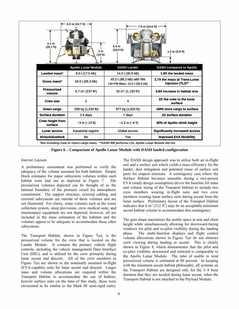
Figure 6 – Comparison of Apollo Lunar Module with DASH landed configuration
6.4 m (20.9 ft) 1.2 m (3.8 ft)
Improved EVA flexibilityYesNoAirlock/dustlock
Significantly increased accessGlobal accessEquatorial regionsLunar access
40% of Apollo climb height~1.2 m (~4 ft) ~3 m (~10 ft)Crew height from surface
2X surface duration7 days3.5 daysSurface duration
Down cargo
Crew size
Pressurized volume
Gross mass*
Landed mass*
~60% more cargo to surface877 kg (1,933 lb)558 kg (1,230 lb)
2X the crew to the lunar surface42
4.8X increase in habitat size32 m3 (1,130 ft3) 6.7 m3 (237 ft3)
2.7X the mass at Trans-Lunar Injection (TLI)**
45.0 t (99.2 klb) with RMLM+PM Mass: 15.0 t (33.0 klb)
16.5 t (36.3 klb)
1.8X the landed mass14.0 t (30.9 klb)8.0 t (17.5 klb)
DASH compared to ApolloDASH LanderApollo Lunar Module
6.0 m (19.7 ft)
*Not including crew or return cargo mass. **DASH RM performs LOI, Apollo Lunar Module did not.
7.5 m (24.6 ft)
6.1 m(20.1 ft)
3 m(10 ft)
Interior Layouts
A preliminary assessment was performed to verify the adequacy of the volume assumed for both habitats. Simple block estimates for major subsystem volumes within each habitat were laid out as depicted in Figure 7. The pressurized volumes depicted can be thought of as the internal boundary of the pressure vessel for atmospheric containment. The support structure, external cabling, and external subsystems are outside of these volumes and are not illustrated. For clarity, some volumes such as the waste collection system, sleep provisions, crew medical suite, and maintenance equipment are not depicted; however, all are included in the mass estimation of the habitats and the volumes appear to be adequate to accommodate these other subsystems.
The Transport Habitat, shown in Figure 7(a), is the pressurized volume for the crew that is located on the Lander Module. It contains the primary vehicle flight controls, including the vehicle management Data Interface Unit (DIU), and is utilized by the crew primarily during lunar ascent and descent. All of the crew members in Figure 7(a) are shown in the nominally assumed in-flight (EVA-capable) suits for lunar ascent and descent. Larger mass and volume allocations are required within the Transport Habitat to accommodate the use of bulkier, heavier surface suits (at the time of this study, these were envisioned to be similar to the Mark III semi-rigid suits).
The DASH design approach was to utilize both an in-flight suit and a surface suit which yields a mass efficiency for the lander, dust mitigation and potential reuse of surface suit parts for outpost missions. A contingency case where the Surface Habitat becomes unusable during a two-person EVA (study design assumption) drives the baseline for mass and volume sizing of the Transport Habitat to include two crew members wearing in-flight suits and two crew members wearing lunar surface suits during ascent from the lunar surface. Preliminary layout of the Transport Habitat indicates that 6 m3 (212 ft3) may be an acceptable minimum ascent habitat volume to accommodate this contingency.
The gem shape maximizes the usable space at arm and chest height while simultaneously allowing for downward-facing windows for pilot and co-pilot visibility during the landing phase. The multi-function displays and flight control volume allocations shown in Figure 7(a) do not obstruct crew viewing during landing or ascent. This is clearly shown in Figure 8, which demonstrates that the pilot and co-pilot visibility downward and outward is comparable to the Apollo Lunar Module. The ratio of usable to total pressurized volume is estimated at 80 percent. In keeping with the minimum ascent habitat philosophy, all systems on the Transport Habitat are designed only for the 3−8 hour duration that they are needed during lunar ascent, when the Transport Habitat is not attached to the Payload Module.
9
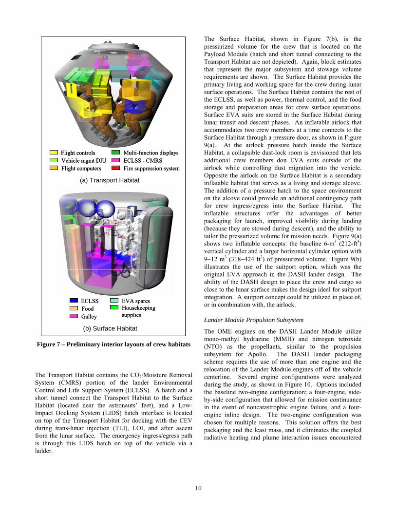
Figure 7 – Preliminary interior layouts of crew habitats
The Transport Habitat contains the CO2/Moisture Removal System (CMRS) portion of the lander Environmental Control and Life Support System (ECLSS). A hatch and a short tunnel connect the Transport Habitat to the Surface Habitat (located near the astronauts’ feet), and a Low-Impact Docking System (LIDS) hatch interface is located on top of the Transport Habitat for docking with the CEV during trans-lunar injection (TLI), LOI, and after ascent from the lunar surface. The emergency ingress/egress path is through this LIDS hatch on top of the vehicle via a ladder.
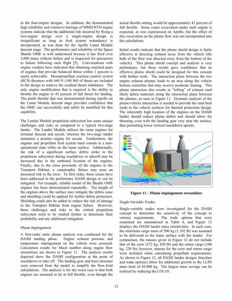
The Surface Habitat, shown in Figure 7(b), is the pressurized volume for the crew that is located on the Payload Module (hatch and short tunnel connecting to the Transport Habitat are not depicted). Again, block estimates that represent the major subsystem and stowage volume requirements are shown. The Surface Habitat provides the primary living and working space for the crew during lunar surface operations. The Surface Habitat contains the rest of the ECLSS, as well as power, thermal control, and the food storage and preparation areas for crew surface operations. Surface EVA suits are stored in the Surface Habitat during lunar transit and descent phases. An inflatable airlock that accommodates two crew members at a time connects to the Surface Habitat through a pressure door, as shown in Figure 9(a). At the airlock pressure hatch inside the Surface Habitat, a collapsible dust-lock room is envisioned that lets additional crew members don EVA suits outside of the airlock while controlling dust migration into the vehicle. Opposite the airlock on the Surface Habitat is a secondary inflatable habitat that serves as a living and storage alcove. The addition of a pressure hatch to the space environment on the alcove could provide an additional contingency path for crew ingress/egress into the Surface Habitat. The inflatable structures offer the advantages of better packaging for launch, improved visibility during landing (because they are stowed during descent), and the ability to tailor the pressurized volume for mission needs. Figure 9(a) shows two inflatable concepts: the baseline 6-m3 (212-ft3) vertical cylinder and a larger horizontal cylinder option with 9−12 m3 (318−424 ft3) of pressurized volume. Figure 9(b) illustrates the use of the suitport option, which was the original EVA approach in the DASH lander design. The ability of the DASH design to place the crew and cargo so close to the lunar surface makes the design ideal for suitport integration. A suitport concept could be utilized in place of, or in combination with, the airlock.
Flight controlsVehicle mgmt DIUFlight computers
Multi-function displaysECLSS - CMRSFire suppression system
Flight controlsVehicle mgmt DIUFlight computers
Multi-function displaysECLSS - CMRSFire suppression system
ECLSSFood Housekeeping
supplies
EVA spares
Galley
ECLSSFood Housekeeping
supplies
EVA spares
Galley
(a) Transport Habitat
(b) Surface HabitatLander Module Propulsion Subsystem
The OME engines on the DASH Lander Module utilize mono-methyl hydrazine (MMH) and nitrogen tetroxide (NTO) as the propellants, similar to the propulsion subsystem for Apollo. The DASH lander packaging scheme requires the use of more than one engine and the relocation of the Lander Module engines off of the vehicle centerline. Several engine configurations were analyzed during the study, as shown in Figure 10. Options included the baseline two-engine configuration; a four-engine, side-by-side configuration that allowed for mission continuance in the event of noncatastrophic engine failure, and a four-engine inline design. The two-engine configuration was chosen for multiple reasons. This solution offers the best packaging and the least mass, and it eliminates the coupled radiative heating and plume interaction issues encountered
10
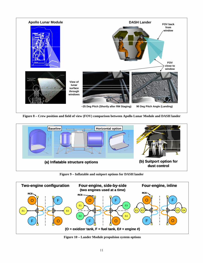
Figure 8 – Crew position and field of view (FOV) comparison between Apollo Lunar Module and DASH lander
Apollo Lunar Module DASH Lander
View of lunar
surface through windows
~25 Deg Pitch (Shortly after RM Staging) 90 Deg Pitch Angle (Landing)
FOV back from
window
FOV close to window
Figure 9 – Inflatable and suitport options for DASH lander
Baseline Horizontal option
(a) Inflatable structure options (b) Suitport option for dust control
Baseline Horizontal option
(a) Inflatable structure options (b) Suitport option for dust control
Figure 10 – Lander Module propulsion system options
Two-engine configuration
E2E1
F O
FO
RCS
Four-engine, side-by-side(two engines used at a time)
RCS
E1
E2 E4
E3
F
O
O
F
Four-engine, inline
E1 E2 E3 E4
F O
FO
RCS
(O = oxidizer tank, F = fuel tank, E# = engine #)
Two-engine configuration
E2E1
F O
FO
RCS
E2E1
F O
FO
RCS
Four-engine, side-by-side(two engines used at a time)
RCS
E1
E2 E4
E3
F
O
O
FRCS
E1
E2 E4
E3
F
O
O
F
Four-engine, inline
E1 E2 E3 E4
F O
FO
RCS
E1 E2 E3 E4
F O
FO
RCS
(O = oxidizer tank, F = fuel tank, E# = engine #)
11
in the four-engine designs. In addition, the demonstrated high reliability and extensive heritage of MMH/NTO engine systems indicate that the additional risk incurred by flying a two-engine design over a single-engine design is insignificant as long as feed system redundancy is incorporated, as was done for the Apollo Lunar Module descent stage. The performance and reliability of the Space Shuttle OME is well understood because it has fired over 2,000 times without failure and is inspected for precursors to failure following each flight [5]. Conversations with engine vendors have indicated that obtaining matched pairs of engines that provide balanced thrust within 1 percent is easily achievable. Monopropellant reaction control system (RCS) thrusters with 444 N (100 lbf) of thrust are included in the design to remove the residual thrust imbalance. The only engine modification that is required is the ability to throttle the engine to 43 percent of full thrust for landing. The pintle throttle that was demonstrated during Apollo on the Lunar Module descent stage provides confidence that the OME can successfully and safely be modified for this capability.
The Lander Module propulsion subsystem has some unique challenges and risks as compared to a typical two-stage lander. The Lander Module utilizes the same engines for terminal descent and ascent, whereas the two-stage lander maintains a pristine engine for ascent. Furthermore, the engines and propellant feed system must remain in a non-operational state while on the lunar surface. Additionally, the risk of a significant surface debris strike to the propulsion subsystem during touchdown or takeoff may be increased due to the outboard location of the engines. Finally, due to the close proximity of the engines to the Transport Habitat, a catastrophic failure may pose an increased risk to the crew. To first order, these issues have been addressed in the preliminary DASH design or can be mitigated. For example, reliable restart of the Shuttle OME engines has been demonstrated repeatedly. The height of the engines above the surface may mitigate the debris issue and shielding could be applied for further debris protection. Shielding could also be added to reduce the risk of damage to the Transport Habitat from engine failure. However, these challenges and risks to the critical propulsion subsystem need to be studied further to determine their probability and any additional mitigation.
Plume Impingement
A first-order static plume analysis was conducted for the DASH landing phase. Engine exhaust pressure and temperature impingement on the vehicle were assessed. Calculation results for Mach number along engine flow streamlines are shown in Figure 11. The analysis results depicted show the DASH configuration at the point of touchdown or take off. The landing gear and truss structure were removed from the model to simplify the flow-field calculations. The analysis is for the worst case in that both engines are assumed to be at full throttle, even though the
actual throttle setting would be approximately 43 percent of full throttle. Some crater excavation under each engine is expected, as was experienced on Apollo, but the effect of this excavation on the plume flow was not incorporated into the calculations.
Initial results indicate that the plume shield design is fairly effective at directing exhaust away from the vehicle (the bulk of the flow was directed away from the bottom of the vehicle). This plume shield concept and analysis is very preliminary, but these results gave confidence that an effective plume shield could be designed for this concept with further work. The interaction plane between the two engine exhaust plumes leads to an area along the vehicle bottom centerline that may receive moderate heating. This plume interaction also results in “lofting” of exhaust (and likely debris material) along the interaction plane between the plumes, as seen in Figure 11. Dynamic analysis of the plume/vehicle interaction is needed to provide the total heat loads to the vehicle surfaces for thermal protection design. The inherently high location of the engines on the DASH lander should reduce plume debris and should allow for thrusting even with the landing gear very near the surface, thus permitting lower vertical touchdown speeds.
Mach5.0753.8072.5381.2690.000
Figure 11 – Plume impingement streamlines
Single-Variable Trades
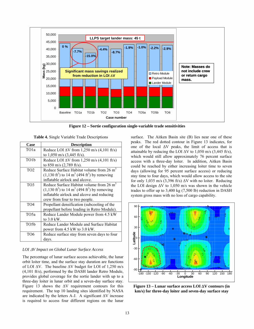
Single-variable trades were investigated for the DASH concept to determine the sensitivity of the concept to various requirements. The trade options that were examined are summarized in Table 4, and Figure 12 displays the DASH lander mass sensitivities. In each case, the minimum cargo mass of 500 kg (1,102 lb) was assumed to be delivered to the lunar surface with the lander. For comparison, the masses given in Figure 12 do not include that of the crew (372 kg; 820 lb) and the return cargo (100 kg; 220 lb); however, masses for the crew and return cargo were included when calculating propellant requirements. As shown in Figure 12, all DASH lander designs (baseline and trade options) allow for additional growth to the LLPS mass limit of 45,000 kg. The largest mass savings can be realized by reducing the LOI ΔV.
12
0
5,000
10,000
15,000
20,000
25,000
30,000
35,000
40,000
45,000
50,000
Baseline TO1a TO1b TO2 TO3 TO4 TO5a TO5b TO6
Case number
Mas
s (k
g)
Retro ModulePayload ModuleLander Module
LLPS target lander mass: 45 t
-7.7%-15.0%
-4.4%-8.7%
Significant mass savings realized from reduction in LOI ΔV
0 % -1.9% -1.0% -2.2% -2.9%
Note:not inor returnmass.
Masses do clude crew
cargo
Figure 12 – Sortie configuration single-variable trade sensitivities
Table 4. Single Variable Trade Descriptions
Case Description TO1a Reduce LOI ΔV from 1,250 m/s (4,101 ft/s)
to 1,050 m/s (3,445 ft/s). TO1b Reduce LOI ΔV from 1,250 m/s (4,101 ft/s)
to 850 m/s (2,789 ft/s). TO2 Reduce Surface Habitat volume from 26 m3
(1,130 ft3) to 14 m3 (494 ft3) by removing inflatable airlock and alcove.
TO3 Reduce Surface Habitat volume from 26 m3 (1,130 ft3) to 14 m3 (494 ft3) by removing inflatable airlock and alcove and reducing crew from four to two people.
TO4 Propellant densification (subcooling of the propellant before loading in Retro Module).
TO5a Reduce Lander Module power from 4.5 kW to 3.0 kW.
TO5b Reduce Lander Module and Surface Habitat power from 4.5 kW to 3.0 kW.
TO6 Reduce surface stay from seven days to four days.
13
LOI ΔV Impact on Global Lunar Surface Access
The percentage of lunar surface access achievable, the lunar orbit loiter time, and the surface stay duration are functions of LOI ΔV. The baseline ΔV budget for LOI of 1,250 m/s (4,101 ft/s), performed by the DASH lander Retro Module, provides global coverage for the sortie lander with up to a three-day loiter in lunar orbit and a seven-day surface stay. Figure 13 shows the ΔV requirement contours for this requirement. The top 10 landing sites identified by NASA are indicated by the letters A-J. A significant ΔV increase is required to access four different regions on the lunar
surface. The Aitken Basin site (B) lies near one of these peaks. The red dotted contour in Figure 13 indicates, for one of the local ΔV peaks, the limit of access that is attainable by reducing the LOI ΔV to 1,050 m/s (3,445 ft/s), which would still allow approximately 76 percent surface access with a three-day loiter. In addition, Aitken Basin could be reached by either increasing loiter time to seven days (allowing for 95 percent surface access) or reducing stay time to four days, which would allow access to the site for only 1,035 m/s (3,396 ft/s) ΔV with no loiter. Reducing the LOI design ΔV to 1,050 m/s was shown in the vehicle trades to offer up to 3,400 kg (7,500 lb) reduction in DASH system gross mass with no loss of cargo capability.
Figure 13 – Lunar surface access LOI ΔV contours (in km/s) for three-day loiter and seven-day surface stay
EE
AA
JJ
DD
GG FF
HH II
CC
BB
0.9
0.90.9
0.90.90.9
0.9
0.9
0.95
0.95
0.95
0.95
0.95
0.95
0.95
0.95
0.95
0.95
0.95
0.95
1
1
1
1
1
1
1
1
1
1
1.05
1.05 1.05
1.05
1.05
1.05
1.05
1.05
1.1
1.1
1.1
1.1
1.1
1.1
1.1
1.15
1.15
1.15
1.15 1.15
1.2
1.2
1.2
1.25
1.25
Longitude
Latit
ude
-180 -150 -120 -90 -60 -30 0 30 60 90 120 150 180-90
-60
-30
0
30
60
90
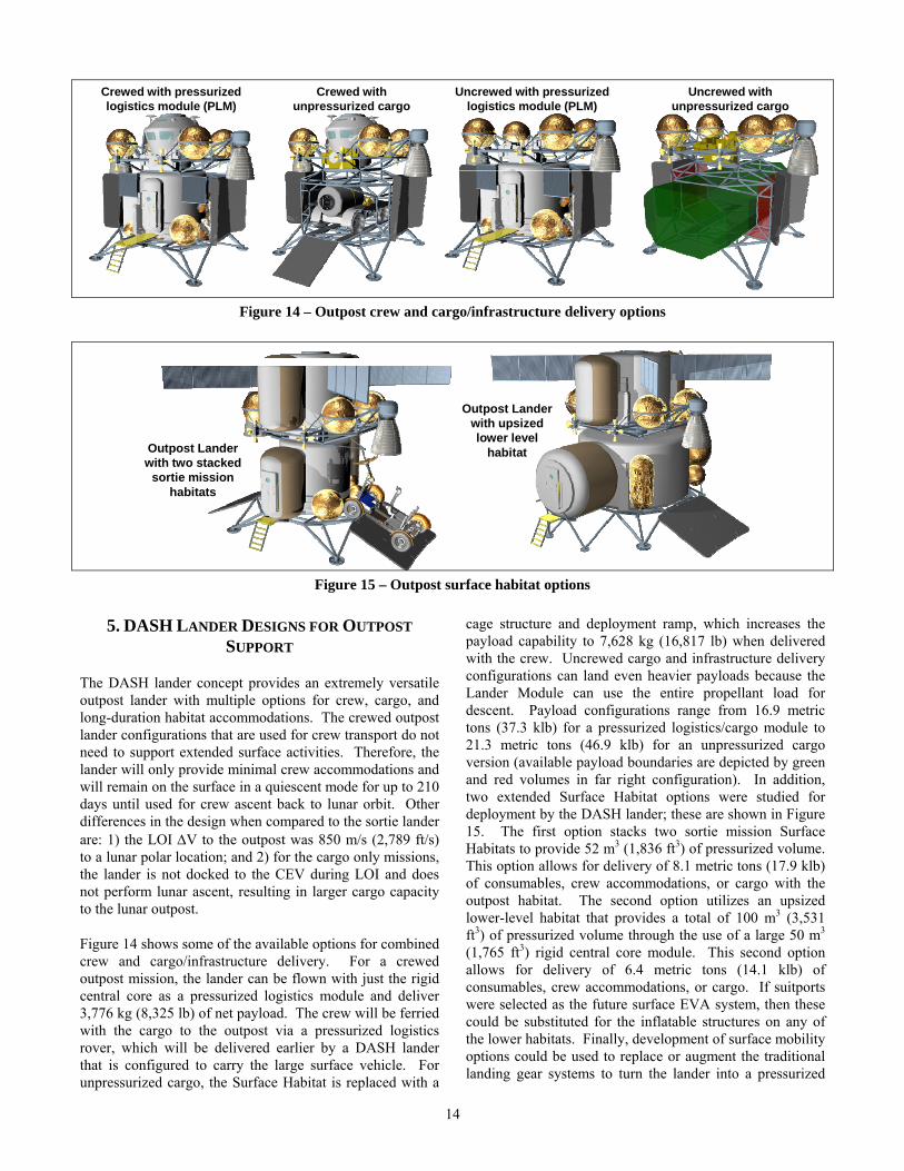
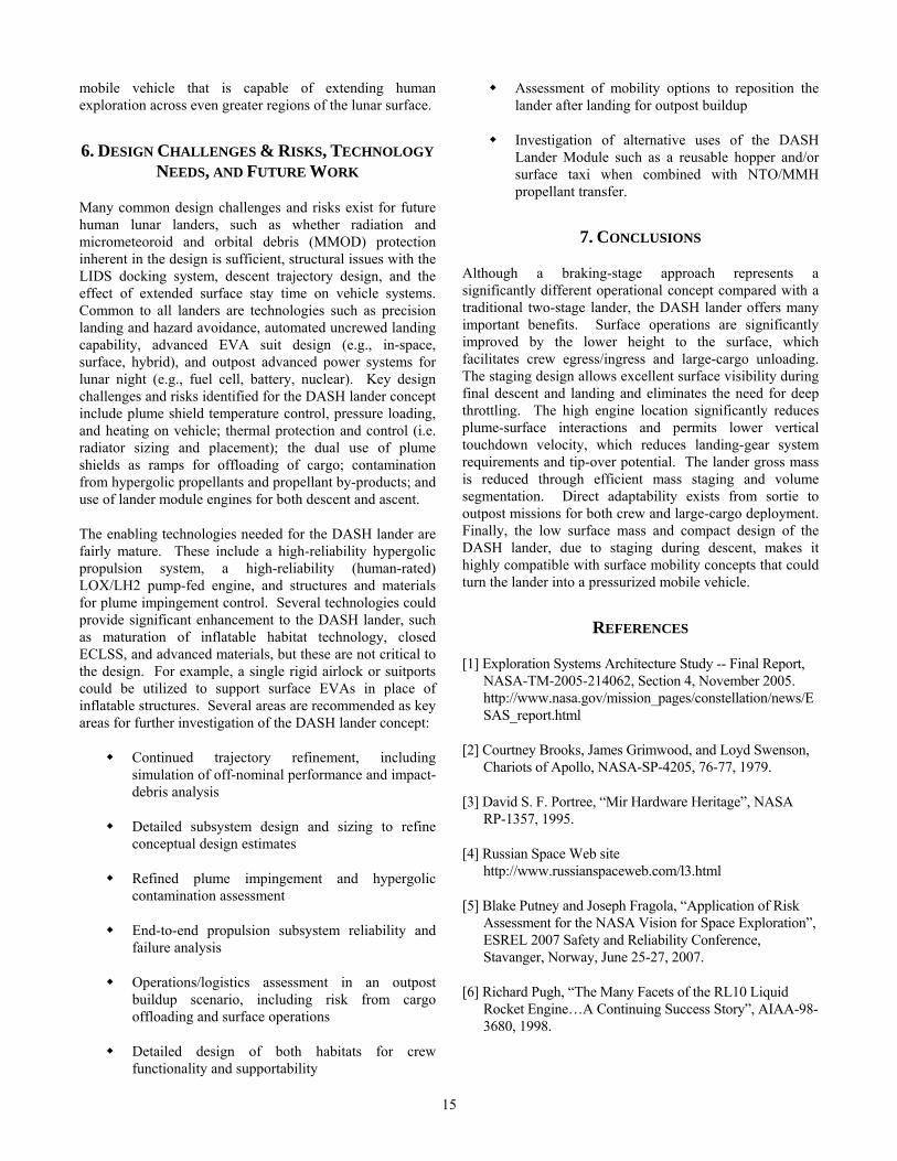
Figure 14 – Outpost crew and cargo/infrastructure delivery options
Crewed with pressurized logistics module (PLM)
Crewed with unpressurized cargo
Uncrewed with pressurized logistics module (PLM)
Uncrewed with unpressurized cargo
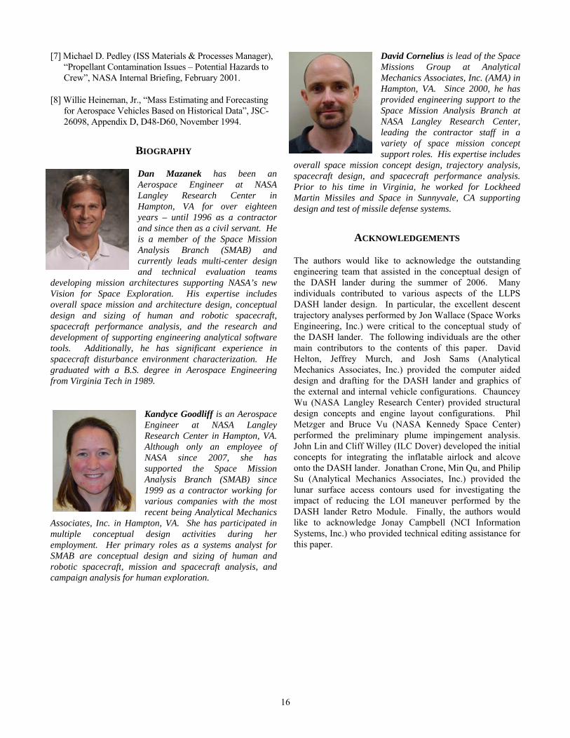
Figure 15 – Outpost surface habitat options
Outpost Lander with two stacked
sortie mission habitats
Outpost Lander with upsized lower level
habitat
5. DASH LANDER DESIGNS FOR OUTPOST
SUPPORT
The DASH lander concept provides an extremely versatile outpost lander with multiple options for crew, cargo, and long-duration habitat accommodations. The crewed outpost lander configurations that are used for crew transport do not need to support extended surface activities. Therefore, the lander will only provide minimal crew accommodations and will remain on the surface in a quiescent mode for up to 210 days until used for crew ascent back to lunar orbit. Other differences in the design when compared to the sortie lander are: 1) the LOI ΔV to the outpost was 850 m/s (2,789 ft/s) to a lunar polar location; and 2) for the cargo only missions, the lander is not docked to the CEV during LOI and does not perform lunar ascent, resulting in larger cargo capacity to the lunar outpost.
Figure 14 shows some of the available options for combined crew and cargo/infrastructure delivery. For a crewed outpost mission, the lander can be flown with just the rigid central core as a pressurized logistics module and deliver 3,776 kg (8,325 lb) of net payload. The crew will be ferried with the cargo to the outpost via a pressurized logistics rover, which will be delivered earlier by a DASH lander that is configured to carry the large surface vehicle. For unpressurized cargo, the Surface Habitat is replaced with a
cage structure and deployment ramp, which increases the payload capability to 7,628 kg (16,817 lb) when delivered with the crew. Uncrewed cargo and infrastructure delivery configurations can land even heavier payloads because the Lander Module can use the entire propellant load for descent. Payload configurations range from 16.9 metric tons (37.3 klb) for a pressurized logistics/cargo module to 21.3 metric tons (46.9 klb) for an unpressurized cargo version (available payload boundaries are depicted by green and red volumes in far right configuration). In addition, two extended Surface Habitat options were studied for deployment by the DASH lander; these are shown in Figure 15. The first option stacks two sortie mission Surface Habitats to provide 52 m3 (1,836 ft3) of pressurized volume. This option allows for delivery of 8.1 metric tons (17.9 klb) of consumables, crew accommodations, or cargo with the outpost habitat. The second option utilizes an upsized lower-level habitat that provides a total of 100 m3 (3,531 ft3) of pressurized volume through the use of a large 50 m3 (1,765 ft3) rigid central core module. This second option allows for delivery of 6.4 metric tons (14.1 klb) of consumables, crew accommodations, or cargo. If suitports were selected as the future surface EVA system, then these could be substituted for the inflatable structures on any of the lower habitats. Finally, development of surface mobility options could be used to replace or augment the traditional landing gear systems to turn the lander into a pressurized
14
mobile vehicle that is capable of extending human exploration across even greater regions of the lunar surface.
6. DESIGN CHALLENGES & RISKS, TECHNOLOGY NEEDS, AND FUTURE WORK
Many common design challenges and risks exist for future human lunar landers, such as whether radiation and micrometeoroid and orbital debris (MMOD) protection inherent in the design is sufficient, structural issues with the LIDS docking system, descent trajectory design, and the effect of extended surface stay time on vehicle systems. Common to all landers are technologies such as precision landing and hazard avoidance, automated uncrewed landing capability, advanced EVA suit design (e.g., in-space, surface, hybrid), and outpost advanced power systems for lunar night (e.g., fuel cell, battery, nuclear). Key design challenges and risks identified for the DASH lander concept include plume shield temperature control, pressure loading, and heating on vehicle; thermal protection and control (i.e. radiator sizing and placement); the dual use of plume shields as ramps for offloading of cargo; contamination from hypergolic propellants and propellant by-products; and use of lander module engines for both descent and ascent.
The enabling technologies needed for the DASH lander are fairly mature. These include a high-reliability hypergolic propulsion system, a high-reliability (human-rated) LOX/LH2 pump-fed engine, and structures and materials for plume impingement control. Several technologies could provide significant enhancement to the DASH lander, such as maturation of inflatable habitat technology, closed ECLSS, and advanced materials, but these are not critical to the design. For example, a single rigid airlock or suitports could be utilized to support surface EVAs in place of inflatable structures. Several areas are recommended as key areas for further investigation of the DASH lander concept:
Continued trajectory refinement, including simulation of off-nominal performance and impact- debris analysis
Detailed subsystem design and sizing to refine conceptual design estimates
Refined plume impingement and hypergolic contamination assessment
End-to-end propulsion subsystem reliability and failure analysis
Operations/logistics assessment in an outpost buildup scenario, including risk from cargo offloading and surface operations
Detailed design of both habitats for crew functionality and supportability
Assessment of mobility options to reposition the lander after landing for outpost buildup
Investigation of alternative uses of the DASH Lander Module such as a reusable hopper and/or surface taxi when combined with NTO/MMH propellant transfer.
7. CONCLUSIONS
Although a braking-stage approach represents a significantly different operational concept compared with a traditional two-stage lander, the DASH lander offers many important benefits. Surface operations are significantly improved by the lower height to the surface, which facilitates crew egress/ingress and large-cargo unloading. The staging design allows excellent surface visibility during final descent and landing and eliminates the need for deep throttling. The high engine location significantly reduces plume-surface interactions and permits lower vertical touchdown velocity, which reduces landing-gear system requirements and tip-over potential. The lander gross mass is reduced through efficient mass staging and volume segmentation. Direct adaptability exists from sortie to outpost missions for both crew and large-cargo deployment. Finally, the low surface mass and compact design of the DASH lander, due to staging during descent, makes it highly compatible with surface mobility concepts that could turn the lander into a pressurized mobile vehicle.
REFERENCES
[1] Exploration Systems Architecture Study -- Final Report, NASA-TM-2005-214062, Section 4, November 2005. http://www.nasa.gov/mission_pages/constellation/news/ESAS_report.html
[2] Courtney Brooks, James Grimwood, and Loyd Swenson, Chariots of Apollo, NASA-SP-4205, 76-77, 1979.
[3] David S. F. Portree, “Mir Hardware Heritage”, NASA RP-1357, 1995.
[4] Russian Space Web site http://www.russianspaceweb.com/l3.html
[5] Blake Putney and Joseph Fragola, “Application of Risk Assessment for the NASA Vision for Space Exploration”, ESREL 2007 Safety and Reliability Conference, Stavanger, Norway, June 25-27, 2007.
[6] Richard Pugh, “The Many Facets of the RL10 Liquid Rocket Engine…A Continuing Success Story”, AIAA-98-3680, 1998.
15
16
David Cornelius is lead of the Space Missions Group at Analytical Mechanics Associates, Inc. (AMA) in Hampton, VA. Since 2000, he has provided engineering support to the Space Mission Analysis Branch at NASA Langley Research Center, leading the contractor staff in a variety of space mission concept support roles. His expertise includes
overall space mission concept design, trajectory analysis, spacecraft design, and spacecraft performance analysis. Prior to his time in Virginia, he worked for Lockheed Martin Missiles and Space in Sunnyvale, CA supporting design and test of missile defense systems.
[7] Michael D. Pedley (ISS Materials & Processes Manager), “Propellant Contamination Issues – Potential Hazards to Crew”, NASA Internal Briefing, February 2001.
[8] Willie Heineman, Jr., “Mass Estimating and Forecasting for Aerospace Vehicles Based on Historical Data”, JSC-26098, Appendix D, D48-D60, November 1994.
BIOGRAPHY
Dan Mazanek has been an Aerospace Engineer at NASA Langley Research Center in Hampton, VA for over eighteen years – until 1996 as a contractor and since then as a civil servant. He is a member of the Space Mission Analysis Branch (SMAB) and currently leads multi-center design and technical evaluation teams
developing mission architectures supporting NASA’s new Vision for Space Exploration. His expertise includes overall space mission and architecture design, conceptual design and sizing of human and robotic spacecraft, spacecraft performance analysis, and the research and development of supporting engineering analytical software tools. Additionally, he has significant experience in spacecraft disturbance environment characterization. He graduated with a B.S. degree in Aerospace Engineering from Virginia Tech in 1989.
ACKNOWLEDGEMENTS
The authors would like to acknowledge the outstanding engineering team that assisted in the conceptual design of the DASH lander during the summer of 2006. Many individuals contributed to various aspects of the LLPS DASH lander design. In particular, the excellent descent trajectory analyses performed by Jon Wallace (Space Works Engineering, Inc.) were critical to the conceptual study of the DASH lander. The following individuals are the other main contributors to the contents of this paper. David Helton, Jeffrey Murch, and Josh Sams (Analytical Mechanics Associates, Inc.) provided the computer aided design and drafting for the DASH lander and graphics of the external and internal vehicle configurations. Chauncey Wu (NASA Langley Research Center) provided structural design concepts and engine layout configurations. Phil Metzger and Bruce Vu (NASA Kennedy Space Center) performed the preliminary plume impingement analysis. John Lin and Cliff Willey (ILC Dover) developed the initial concepts for integrating the inflatable airlock and alcove onto the DASH lander. Jonathan Crone, Min Qu, and Philip Su (Analytical Mechanics Associates, Inc.) provided the lunar surface access contours used for investigating the impact of reducing the LOI maneuver performed by the DASH lander Retro Module. Finally, the authors would like to acknowledge Jonay Campbell (NCI Information Systems, Inc.) who provided technical editing assistance for this paper.
Kandyce Goodliff is an Aerospace Engineer at NASA Langley Research Center in Hampton, VA. Although only an employee of NASA since 2007, she has supported the Space Mission Analysis Branch (SMAB) since 1999 as a contractor working for various companies with the most recent being Analytical Mechanics
Associates, Inc. in Hampton, VA. She has participated in multiple conceptual design activities during her employment. Her primary roles as a systems analyst for SMAB are conceptual design and sizing of human and robotic spacecraft, mission and spacecraft analysis, and campaign analysis for human exploration.