Embed Size (px)
Citation preview
Design and Construction Guidance for Breakaway Walls Below Elevated Buildings Located in Coastal High Hazard Areas in accordance with the National Flood Insurance Program Technical Bulletin 9 / August 2008
Comments on the Technical Bulletins should be directed to:
Department of Homeland Security FEMA Mitigation Directorate 500 C Street, SW. Washington, D.C. 20472
Technical Bulletin 9-08 replaces Technical Bulletin 9-99, Design and Construction Guidance for Breakaway Walls.
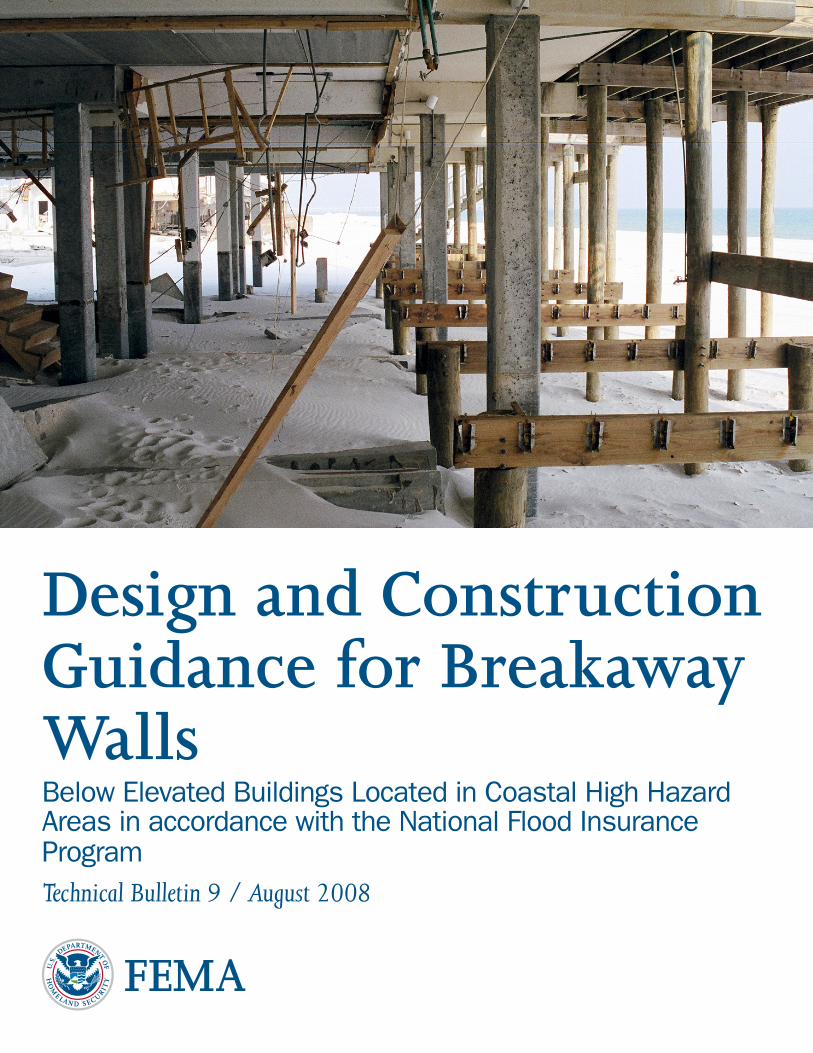
Cover photo: Post-Hurricane Ivan photo of the underside of an elevated V zone building. The break-away walls underneath the building failed as intended during the hurricane.
Table of ContentsIntroduction ..................................................................................................................................1
NFIP Regulations ..........................................................................................................................3
Flood Insurance Considerations .......................................................................................4
Building and Residential Code Considerations ...............................................................5
Wave Loads on Building Elements ...................................................................................5
Performance of Breakaway Walls ......................................................................................5
Options for Enclosing Areas Below Elevated Buildings ...............................................12
Prescriptive Design Method for Breakaway Walls ..........................................................13
Simplified Design Method for Breakaway Walls ............................................................18
Performance-Based Design of Breakaway Walls .............................................................25
Impact of Breakaway Wall Provisions on Other Building Elements ............................26
Construction Materials ....................................................................................................27
Existing Buildings: Repairs, Remodeling, Additions, and Retrofitting ........................28
Recommendations for Coastal A Zones .........................................................................28
The NFIP .....................................................................................................................................30
NFIP Technical Bulletins ............................................................................................................30
Ordering Technical Bulletins .....................................................................................................31
Further Information ...................................................................................................................31
Glossary ........................................................................................................................................32
1Technical BulleTin 9 – auGuST 2008
Introduction
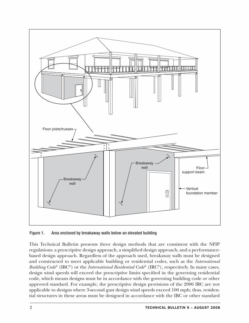
Protecting buildings that are constructed in special flood hazard areas (SFHAs) from dam-age caused by flood forces is an important objective of the National Flood Insurance Program (NFIP). In support of this objective, the NFIP regulations include minimum building design criteria that apply to new construction, repair of substantially damaged buildings, and substan-tial improvements of existing buildings in SFHAs. The base flood is used to delineate SFHAs on Flood Insurance Rate Maps (FIRMs) prepared by the NFIP. The base flood is the flood that has a 1-percent chance of being equaled or exceeded in any given year (commonly called the “100-year” flood). Certain terms used in this Technical Bulletin are defined in the Glossary.
Coastal waves and flooding can exert strong hydrodynamic forces on any building element that is exposed to the waves or flow of water. The NFIP requires that all new buildings, substantially damaged buildings, and substantially improved buildings in Coastal High Hazard Areas (Zones V, VE, and V1030) be elevated to or above the base flood elevation (BFE) on open foundations consisting of piles, posts, piers, or col-umns. These open foundations must be designed to allow waves and water moving at high velocity to flow beneath build-ings.
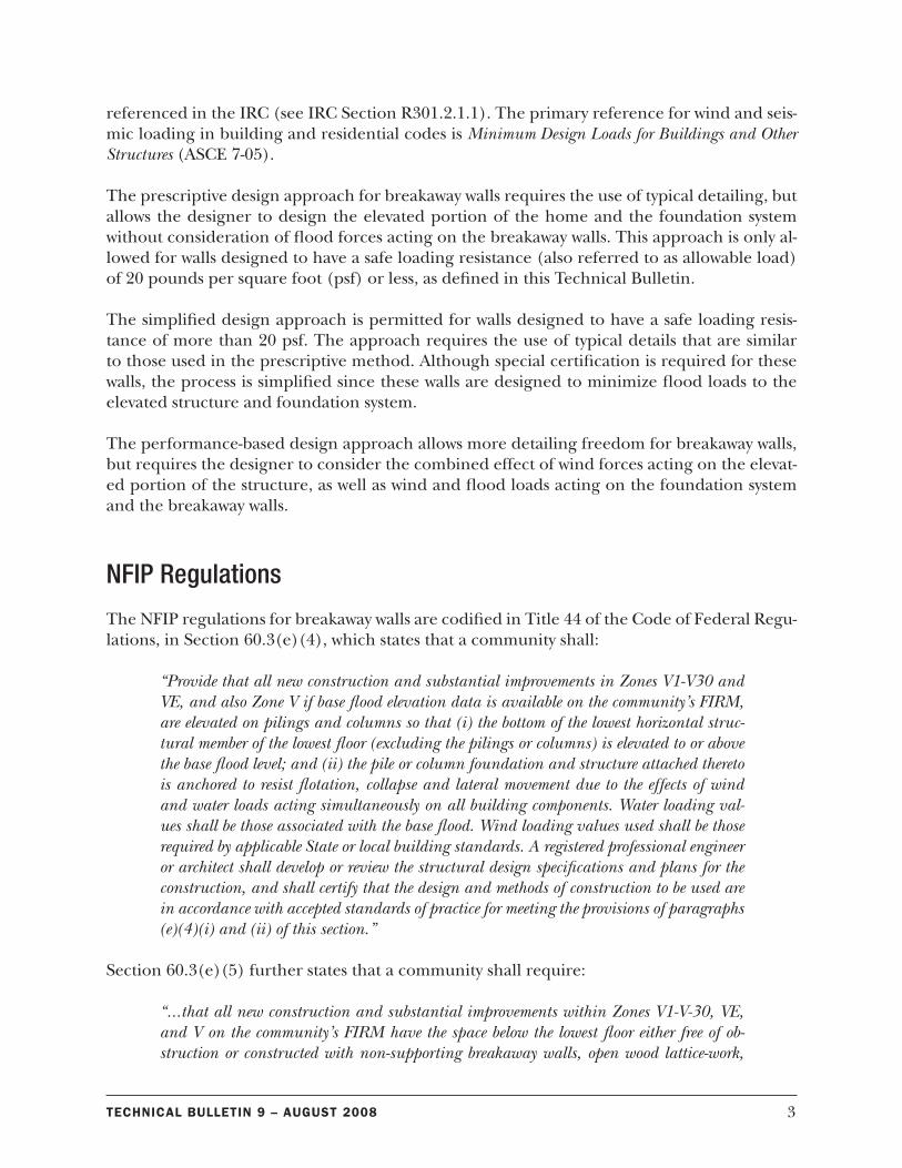
NFIP regulations require that the area below the lowest floor of elevated buildings either be free of obstructions or have any enclosed areas be constructed of non-supporting break-away walls, open lattice-work, or insect screening. The walls, lattice, or screening are intended to collapse under wave loads without causing collapse, displacement, or other structural damage to the elevated building or the supporting founda-tion system (see Figure 1). Obstructions below an elevated building can significantly increase the potential for flood damage by increasing the surface area subject to wave impact and ve-locity flow.
The NFIP regulations also specify that enclosures may be used only for parking of vehicles, building access, or storage; that all materials below the BFE, including materials used to con-struct enclosures, be flood damage-resistant materials; and that construction methods and practices minimize the potential for flood damage.
Specific design requirements for breakaway walls are included in the NFIP regulations. Those parameters were the subject of research on breakaway walls performed for the Federal Emer-gency Management Agency (FEMA) and the National Science Foundation by North Carolina State University and Oregon State University (Tung et al., 1999). The research evaluated fail-ure mechanisms that were demonstrated by full-scale, laboratory wave-tank tests of breakaway wall panels.
Under the NFIP, the “low-est floor” is the floor of the lowest enclosed area of a building. An unfinished or flood-resistant enclosure that is used solely for park-ing of vehicles, building access, or storage is not the lowest floor, provided the enclosure is built in compliance with applicable requirements.
As used by the NFIP, an “enclosure” is an area that is enclosed on all sides by walls.
2 Technical BulleTin 9 – auGuST 2008
This Technical Bulletin presents three design methods that are consistent with the NFIP regulations: a prescriptive design approach, a simplified design approach, and a performance-based design approach. Regardless of the approach used, breakaway walls must be designed and constructed to meet applicable building or residential codes, such as the International Building Code® (IBC®) or the International Residential Code® (IRC®), respectively. In many cases, design wind speeds will exceed the prescriptive limits specified in the governing residential code, which means designs must be in accordance with the governing building code or other approved standard. For example, the prescriptive design provisions of the 2006 IRC are not applicable to designs where 3-second gust design wind speeds exceed 100 mph; thus, residen-tial structures in these areas must be designed in accordance with the IBC or other standard
Figure 1. Area enclosed by breakaway walls below an elevated building
3Technical BulleTin 9 – auGuST 2008
referenced in the IRC (see IRC Section R301.2.1.1). The primary reference for wind and seis-mic loading in building and residential codes is Minimum Design Loads for Buildings and Other Structures (ASCE 7-05).
The prescriptive design approach for breakaway walls requires the use of typical detailing, but allows the designer to design the elevated portion of the home and the foundation system without consideration of flood forces acting on the breakaway walls. This approach is only al-lowed for walls designed to have a safe loading resistance (also referred to as allowable load) of 20 pounds per square foot (psf) or less, as defined in this Technical Bulletin.
The simplified design approach is permitted for walls designed to have a safe loading resis-tance of more than 20 psf. The approach requires the use of typical details that are similar to those used in the prescriptive method. Although special certification is required for these walls, the process is simplified since these walls are designed to minimize flood loads to the elevated structure and foundation system.
The performance-based design approach allows more detailing freedom for breakaway walls, but requires the designer to consider the combined effect of wind forces acting on the elevat-ed portion of the structure, as well as wind and flood loads acting on the foundation system and the breakaway walls.
NFIP Regulations
The NFIP regulations for breakaway walls are codified in Title 44 of the Code of Federal Regu-lations, in Section 60.3(e)(4), which states that a community shall:
“Provide that all new construction and substantial improvements in Zones V1-V30 and VE, and also Zone V if base flood elevation data is available on the community’s FIRM, are elevated on pilings and columns so that (i) the bottom of the lowest horizontal struc-tural member of the lowest floor (excluding the pilings or columns) is elevated to or above the base flood level; and (ii) the pile or column foundation and structure attached thereto is anchored to resist flotation, collapse and lateral movement due to the effects of wind and water loads acting simultaneously on all building components. Water loading val-ues shall be those associated with the base flood. Wind loading values used shall be those required by applicable State or local building standards. A registered professional engineer or architect shall develop or review the structural design specifications and plans for the construction, and shall certify that the design and methods of construction to be used are in accordance with accepted standards of practice for meeting the provisions of paragraphs (e)(4)(i) and (ii) of this section.”
Section 60.3(e)(5) further states that a community shall require:
“...that all new construction and substantial improvements within Zones V1-V-30, VE, and V on the community’s FIRM have the space below the lowest floor either free of ob-struction or constructed with non-supporting breakaway walls, open wood lattice-work,
4 Technical BulleTin 9 – auGuST 2008
or insect screening intended to collapse under wind and water loads without causing col-lapse, displacement, or other structural damage to the elevated portion of the building or supporting foundation system. For the purposes of this section, a breakaway wall shall have a design safe loading resistance of not less than 10 and no more than 20 pounds per square foot. Use of breakaway walls which exceed a design safe loading resistance of 20 pounds per square foot (either by design or when so required by local or State codes) may be permitted only if a registered professional engineer or architect certifies that the designs proposed meet the following conditions: (i) Breakaway wall collapse shall result from a water load less than that which would occur during the base flood; and (ii) The elevated portion of the building and supporting foundation system shall not be subject to collapse, displacement, or other structural damage due to the effects of wind and water loads acting simultaneously on all building components (structural and non-structural). Water load-ing values used shall be those associated with the base flood. Wind loading values used shall be those required by applicable State or local building standards. Such enclosed space shall be useable solely for parking of vehicles, building access, or storage.”
Proposals for substantial improvement of existing buildings in V zones, and proposals to repair those buildings that have sus-tained substantial damage, must comply with the requirements for new construction, including requirements for breakaway walls surrounding enclosed areas below the BFE. As part of issuing permits, community officials must review such propos-als to determine whether they comply with the requirements. Further information on substantial improvement and substan-tial damage is found in Answers to Questions About Substantially Damaged Buildings (FEMA 213).
Flood Insurance Considerations
Elevated buildings in V zones that do not have obstructions or enclosures below the BFE are subject to less flood damage and thus lower rates are used to determine premiums for NFIP flood insurance. Some considerations affecting the rates and costs of NFIP flood insurance for elevated buildings in V zones include:
n The use of an enclosure with breakaway walls increases the premium for the entire building.
n An increase in the flood insurance premium resulting from the presence of an enclosure depends upon the area of the enclosure; substantially higher premiums are charged for enclosures that are 300 square feet or greater in area.
n The presence of garage doors below an elevated building, even if designed in accordance with this Technical Bulletin, may increase the flood insurance premium for the building.
NFIP flood insurance policies have limits on coverage of contents in enclosures under elevat-ed buildings. Designers, contractors, and owners may wish to contact a qualified insurance agent or the NFIP for more information about policy coverage, coverage limits, and costs.
The NFIP Technical Bulletins provide guid-ance on the minimum requirements of the NFIP regulations. Community or State requirements that ex-ceed those of the NFIP take precedence. Design profes-sionals should contact the community to determine whether more restrictive provisions apply to the building or site in question. All other applicable require-ments of the State or local building codes must also be met for buildings in all flood hazard areas.
5Technical BulleTin 9 – auGuST 2008
Building and Residential Code Considerations
The IBC requires that breakaway walls be designed and detailed in accordance with Flood Re-sistant Design and Construction (ASCE 24-05). ASCE 24-05 provides minimum requirements for flood-resistant design and construction of structures that are located in flood hazard areas. It requires breakaway walls and their connections to be in accordance with the flood loads speci-fied in ASCE 7-05. In addition, ASCE 24-05 states that utilities and attendant equipment shall not be mounted on, pass through, or be located along breakaway walls.
The IRC contains NFIP-consistent provisions and requires that the design of breakaway walls be certified by a registered design professional if wind loading values exceed 20 psf. As an al-ternative, the IRC permits the use of ASCE 24-05 for the design of breakaway walls. It should be noted that component and cladding values presented in the IRC exceed 20 psf in locations where the 3-second gust design wind speed equals or exceeds 110 mph.
Wave Loads on Building Elements
Buildings in areas where conditions produce breaking waves are exposed to different loads and more severe loads than are imposed on buildings in flood hazard areas without waves. As a breaking wave passes a pile foundation or other element of an open foundation, the struc-ture experiences an oscillating, high-velocity flow that peaks at the wave crest, just as the wave breaks. While drag forces are imposed on the relatively narrow vertical surfaces of open foun-dations as water moves under the building and past the foundation elements, most of the flow is relatively undisturbed, which makes open foundations an appropriate design in V zones. Water flows past piles under a building in much the same way rivers flow past piles and piers used to support bridges.
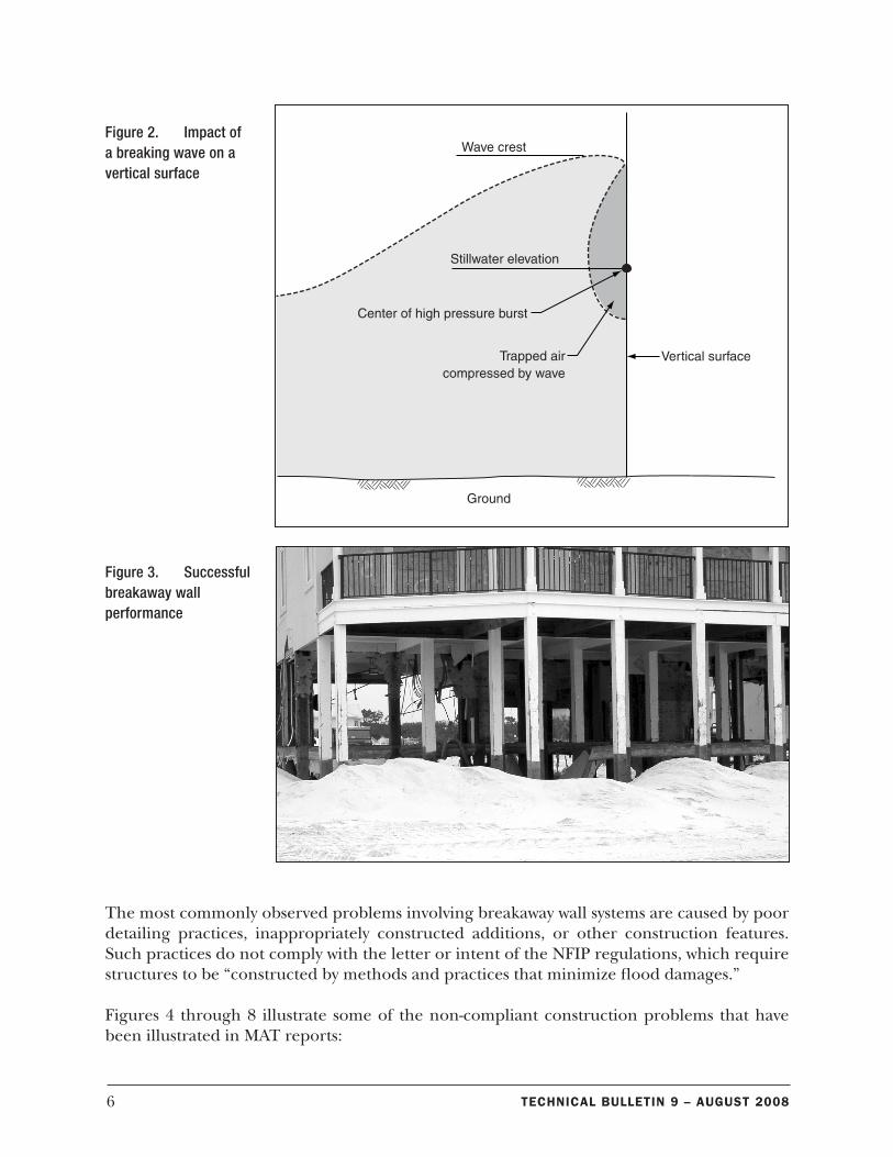
The effect is quite different when a breaking wave hits a wider, relatively continuous, verti-cal surface, such as a wall. When the crest of a breaking wave impacts a wall, a pocket of air is trapped and compressed by the wave (see Figure 2). As the air pocket collapses, an exceed-ingly high-pressure burst (i.e., shock wave) impacts the wall, with the force centered around the stillwater level. Peak pressures from a 5-foot breaking wave can be 100 times higher than the safe loading resistance of 10 to 20 psf that is specified for breakaway walls in the NFIP reg-ulations.
Performance of Breakaway Walls
FEMA’s Mitigation Assessment Team (MAT) Reports
FEMA deploys Mitigation Assessment Teams after some disasters to evaluate the performance of buildings and related infrastructure. MAT reports prepared after significant coastal storms have consistently concluded that breakaway wall systems perform as intended when they are designed and constructed to break away without damaging the elevated home and without becoming debris that can be trapped under buildings. Figure 3 shows an example of success-ful breakaway wall performance. MAT reports have also shown that some breakaway walls have been designed, constructed, or modified in ways that conflict with the NFIP regulations. In many cases, these non-compliant walls have led to unnecessary damage to, or collapse of, elevated structures.
6 Technical BulleTin 9 – auGuST 2008
The most commonly observed problems involving breakaway wall systems are caused by poor detailing practices, inappropriately constructed additions, or other construction features. Such practices do not comply with the letter or intent of the NFIP regulations, which require structures to be “constructed by methods and practices that minimize flood damages.”
Figures 4 through 8 illustrate some of the non-compliant construction problems that have been illustrated in MAT reports:
Figure 2. Impact of a breaking wave on a vertical surface
Figure 3. Successful breakaway wall performance
7Technical BulleTin 9 – auGuST 2008
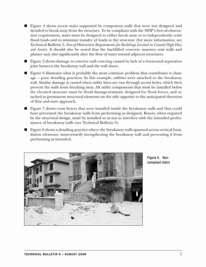
n Figure 4 shows access stairs supported by component walls that were not designed and detailed to break away from the structure. To be compliant with the NFIP’s free-of-obstruc-tion requirement, stairs must be designed to either break away or to independently resist flood loads and to minimize transfer of loads to the structure (for more information, see Technical Bulletin 5, Free-of-Obstruction Requirements for Buildings Located in Coastal High Haz-ard Areas). It should also be noted that the backfilled concrete masonry unit walls and planter may also significantly alter the flow of water toward adjacent structures.
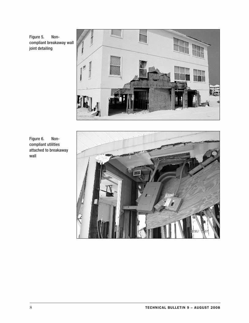
n Figure 5 shows damage to exterior wall covering caused by lack of a horizontal separation joint between the breakaway wall and the wall above.
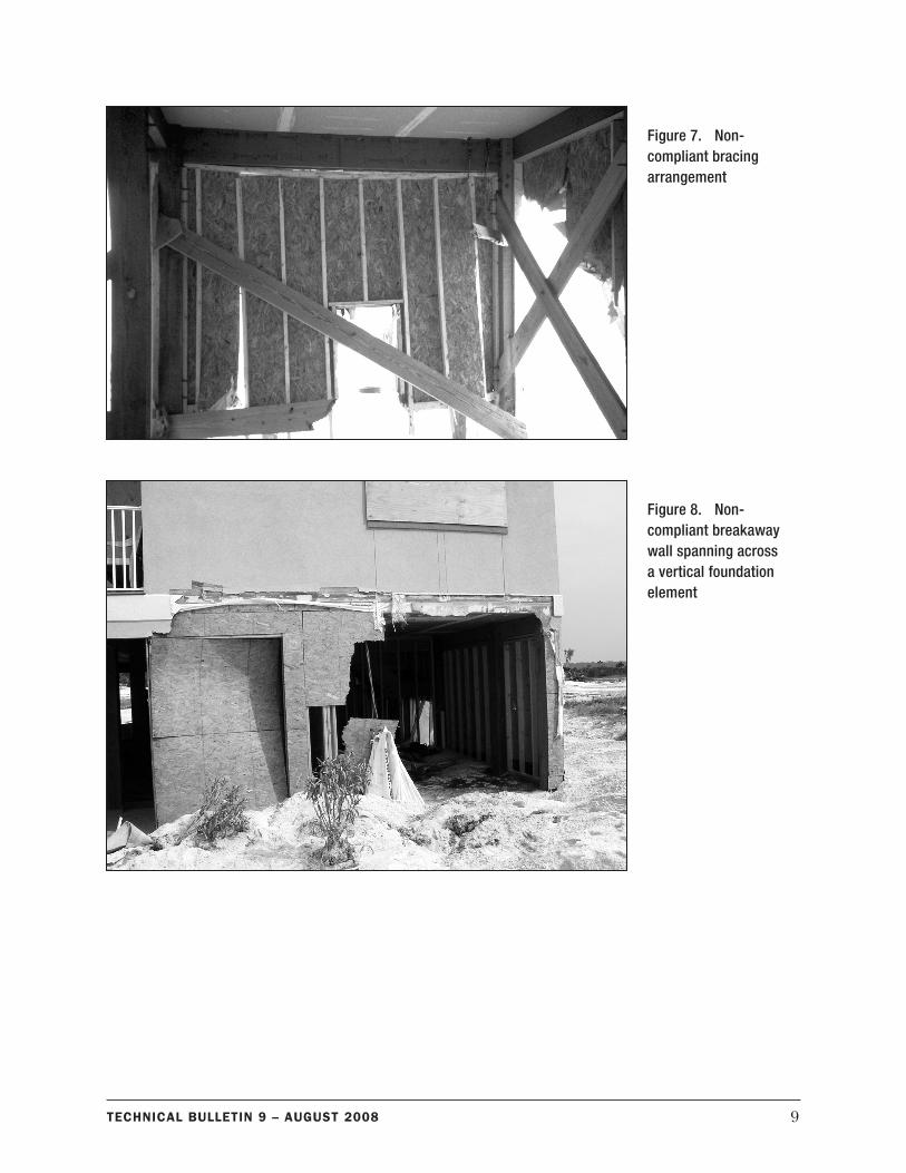
n Figure 6 illustrates what is probably the most common problem that contributes to dam-age – poor detailing practices. In this example, utilities were attached to the breakaway wall. Similar damage is caused when utility lines are run through access holes, which then prevent the walls from breaking away. All utility components that must be installed below the elevated structure must be flood damage-resistant, designed for flood forces, and at-tached to permanent structural elements on the side opposite to the anticipated direction of flow and wave approach.
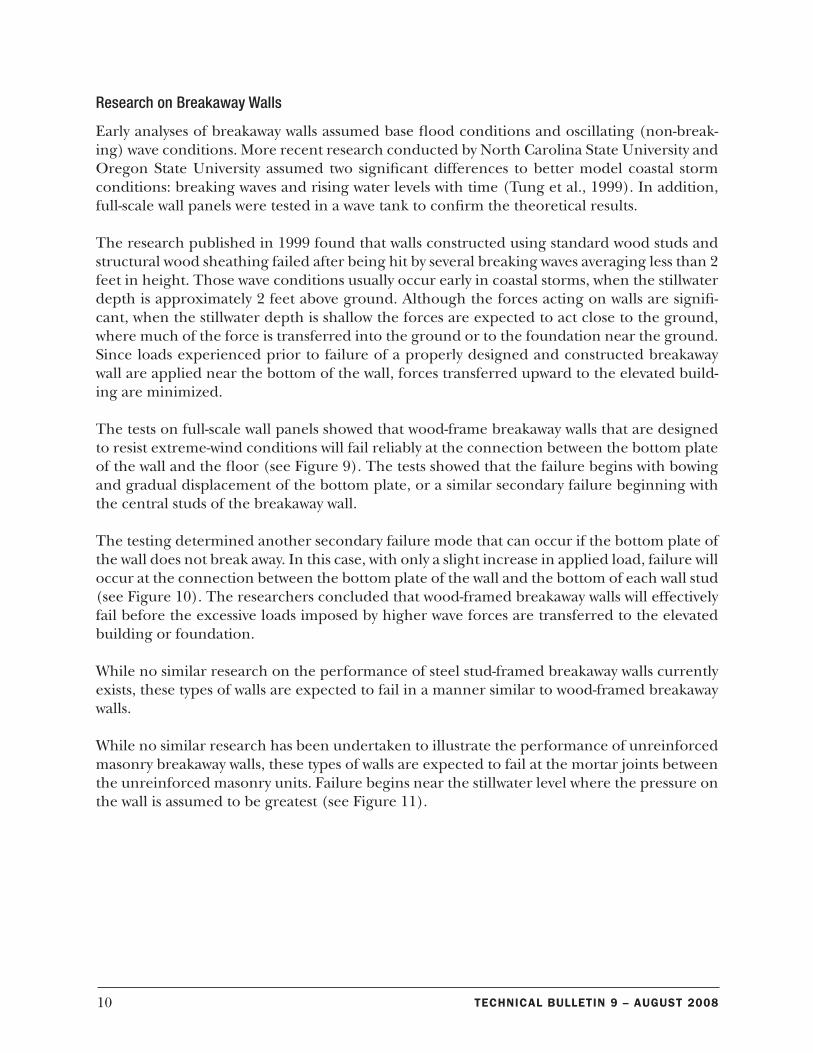
n Figure 7 shows cross braces that were installed inside the breakaway walls and that could have prevented the breakaway walls from performing as designed. Braces, when required by the structural design, must be installed so as not to interfere with the intended perfor-mance of breakaway walls (see Technical Bulletin 5).
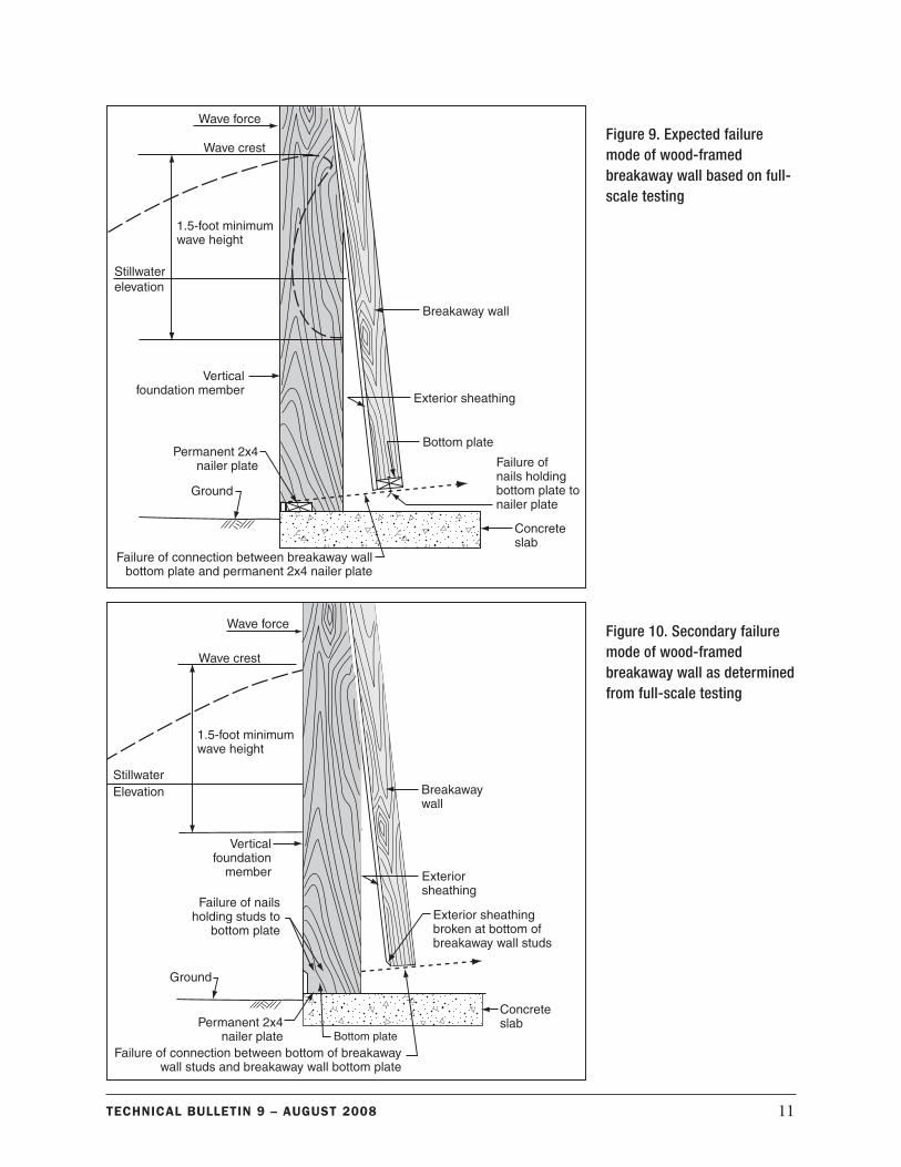
n Figure 8 shows a detailing practice where the breakaway walls spanned across vertical foun-dation elements, unnecessarily strengthening the breakaway wall and preventing it from performing as intended.
Figure 4. Non-compliant stairs
8 Technical BulleTin 9 – auGuST 2008
Figure 5. Non-compliant breakaway wall joint detailing
Figure 6. Non-compliant utilities attached to breakaway wall
9Technical BulleTin 9 – auGuST 2008
Figure 8. Non-compliant breakaway wall spanning across a vertical foundation element
Figure 7. Non-compliant bracing arrangement
10 Technical BulleTin 9 – auGuST 2008
Research on Breakaway Walls
Early analyses of breakaway walls assumed base flood conditions and oscillating (non-break-ing) wave conditions. More recent research conducted by North Carolina State University and Oregon State University assumed two significant differences to better model coastal storm conditions: breaking waves and rising water levels with time (Tung et al., 1999). In addition, full-scale wall panels were tested in a wave tank to confirm the theoretical results.
The research published in 1999 found that walls constructed using standard wood studs and structural wood sheathing failed after being hit by several breaking waves averaging less than 2 feet in height. Those wave conditions usually occur early in coastal storms, when the stillwater depth is approximately 2 feet above ground. Although the forces acting on walls are signifi-cant, when the stillwater depth is shallow the forces are expected to act close to the ground, where much of the force is transferred into the ground or to the foundation near the ground. Since loads experienced prior to failure of a properly designed and constructed breakaway wall are applied near the bottom of the wall, forces transferred upward to the elevated build-ing are minimized.
The tests on full-scale wall panels showed that wood-frame breakaway walls that are designed to resist extreme-wind conditions will fail reliably at the connection between the bottom plate of the wall and the floor (see Figure 9). The tests showed that the failure begins with bowing and gradual displacement of the bottom plate, or a similar secondary failure beginning with the central studs of the breakaway wall.
The testing determined another secondary failure mode that can occur if the bottom plate of the wall does not break away. In this case, with only a slight increase in applied load, failure will occur at the connection between the bottom plate of the wall and the bottom of each wall stud (see Figure 10). The researchers concluded that wood-framed breakaway walls will effectively fail before the excessive loads imposed by higher wave forces are transferred to the elevated building or foundation.
While no similar research on the performance of steel stud-framed breakaway walls currently exists, these types of walls are expected to fail in a manner similar to wood-framed breakaway walls.
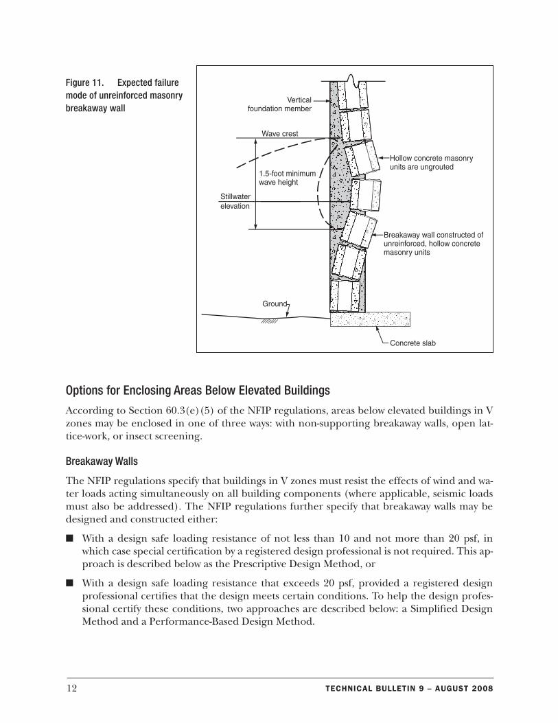
While no similar research has been undertaken to illustrate the performance of unreinforced masonry breakaway walls, these types of walls are expected to fail at the mortar joints between the unreinforced masonry units. Failure begins near the stillwater level where the pressure on the wall is assumed to be greatest (see Figure 11).
11Technical BulleTin 9 – auGuST 2008
Figure 9. Expected failure mode of wood-framed breakaway wall based on full-scale testing
Figure 10. Secondary failure mode of wood-framed breakaway wall as determined from full-scale testing
12 Technical BulleTin 9 – auGuST 2008
Options for Enclosing Areas Below Elevated Buildings
According to Section 60.3(e)(5) of the NFIP regulations, areas below elevated buildings in V zones may be enclosed in one of three ways: with non-supporting breakaway walls, open lat-tice-work, or insect screening.
Breakaway Walls
The NFIP regulations specify that buildings in V zones must resist the effects of wind and wa-ter loads acting simultaneously on all building components (where applicable, seismic loads must also be addressed). The NFIP regulations further specify that breakaway walls may be designed and constructed either:
n With a design safe loading resistance of not less than 10 and not more than 20 psf, in which case special certification by a registered design professional is not required. This ap-proach is described below as the Prescriptive Design Method, or
n With a design safe loading resistance that exceeds 20 psf, provided a registered design professional certifies that the design meets certain conditions. To help the design profes-sional certify these conditions, two approaches are described below: a Simplified Design Method and a Performance-Based Design Method.
Figure 11. Expected failure mode of unreinforced masonry breakaway wall
13Technical BulleTin 9 – auGuST 2008
Open Lattice-Work and Insect Screening
Open lattice-work and insect screening are not considered to be walls or obstructions as long as they will collapse under wind and water loads without causing damage to the building. To increase the likelihood of collapse as intended, it is recommended that the vertical fram-ing members (such as 2x4s) on which the screen or lattice-work is mounted be spaced at least 2 feet apart. Either metal or synthetic mesh insect screening is acceptable. Wood and plastic lattice is available in 4-foot x 8-foot sheets. The material used to fabricate the lattice should be no thicker than ½ inch, and the finished sheet should have an opening ratio of at least 40 percent. (Although the regulations explicitly identify wood lattice, plastic lattice is acceptable provided it meets these recommendations.)
Although not specified in the regulations, areas below elevated building may also be sur-rounded by plastic or wood shutters, slanted slats, or louvers (see Technical Bulletin 5). These materials must meet the following criteria:
n They must be cosmetic in nature,
n The material used for the slats must be no thicker than 1 inch, and
n They must have an opening ratio of at least 40 percent.
Prescriptive Design Method for Breakaway Walls
Walls with a design safe loading resistance of not less than 10 psf and not more than 20 psf are considered breakaway walls and do not require special certification by a registered design professional. This statement has caused much confusion among developers, designers, and lo-cal officials. The intent is to allow flood loads acting on breakaway walls to be neglected when designing the foundation elements and the elevated structure itself. It was never the intent to allow breakaway walls to be designed for wind and seismic pressures that circumvent or lessen local building or residential code requirements. The previously cited research showed that breakaway walls with a design safe loading resistance of not more than 20 psf will fail at very low flood loads (i.e., 1.5-foot wave height). Thus, combining wave and wind loads on breakaway walls with maximum loads acting on an elevated structure and foundation system is unrealistic, and not required when using the prescriptive design method.
Breakaway walls that are built in accordance with the following prescriptive design method are considered to have a design safe loading resistance of approximately 20 psf. Modern building and residential codes used along the Gulf and Atlantic coasts likely will require unfactored design wind pressures that exceed 20 psf. Building codes and material standards no longer permit allowable stress increases for masonry, and thus prohibit unreinforced masonry break-away walls to be designed using this method.
Applicability
The prescriptive design method for wood-framed and steel stud-framed breakaway walls does not require a design professional and is permitted to be used if all of the following conditions are satisfied:
14 Technical BulleTin 9 – auGuST 2008
1. Breakaway wall heights are between 6 and 9 feet, where piles, columns, or piers are spaced between 8 and 12 feet apart (the performance-based methods shall be used for situations that fall outside of these limitations).
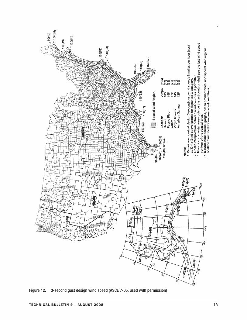
2. The 3-second gust design wind speed does not exceed 110 mph per ASCE 7-05 (see Figure 12) for all parts of breakaway walls, except those parts that are located within 4 feet of a building corner. Walls at building corners are subjected to substantially higher wind loads.
3. The 3-second gust design wind speed does not exceed 100 mph per ASCE 7-05 for those parts of breakaway walls that are located within 4 feet of a building corner.
4. The prescriptive design method is permitted for all Seismic Design Categories identified in ASCE 7-05.
5. Breakaway walls serving as backup for brick veneer or other material that may be damaged by excessive deflections shall not be designed using the prescriptive design method.
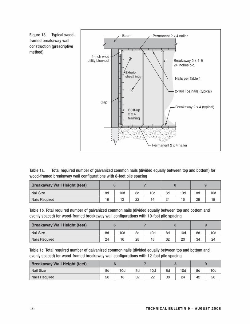
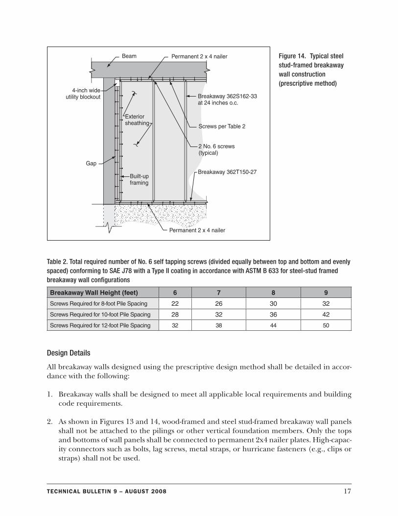
Design Methodology
Wood-framed breakaway walls and steel stud-framed breakaway walls shall be constructed in accordance with Figures 13 and 14, respectively. A note in Figure 13 refers to Table 1; Table 1 is a set of tables presenting alternative nail requirements. A note in Figure 14 refers to Ta-ble 2, which presents requirements for screws. Interpolation for different pile spacings and wall heights is permitted when using these tables. Wood-framed walls shall be constructed us-ing flood damage-resistant, No. 2 Grade Spruce-Pine-Fir or better grade/species (e.g., No. 2 Southern Pine is better as defined by its higher allowable bending stress).
The NFIP does not require installation of flood open-ings (vents) in breakaway walls under buildings in V zones. However, a num-ber of State and local governments do require openings in breakaway walls. Check with the local building official or flood-plain administrator for local requirements. Technical Bulletin 1 provides guid-ance on flood openings.
15Technical BulleTin 9 – auGuST 2008
Figure 12. 3-second gust design wind speed (ASCE 7-05, used with permission)
16 Technical BulleTin 9 – auGuST 2008
Table 1a. Total required number of galvanized common nails (divided equally between top and bottom) for wood-framed breakaway wall configurations with 8-foot pile spacing
Breakaway Wall Height (feet) 6 7 8 9
Nail Size 8d 10d 8d 10d 8d 10d 8d 10d
Nails Required 18 12 22 14 24 16 28 18
Table 1b. Total required number of galvanized common nails (divided equally between top and bottom and evenly spaced) for wood-framed breakaway wall configurations with 10-foot pile spacing
Breakaway Wall Height (feet) 6 7 8 9
Nail Size 8d 10d 8d 10d 8d 10d 8d 10d
Nails Required 24 16 28 18 32 20 34 24
Table 1c. Total required number of galvanized common nails (divided equally between top and bottom and evenly spaced) for wood-framed breakaway wall configurations with 12-foot pile spacing
Breakaway Wall Height (feet) 6 7 8 9
Nail Size 8d 10d 8d 10d 8d 10d 8d 10d
Nails Required 28 18 32 22 38 24 42 28
Figure 13. Typical wood-framed breakaway wall construction (prescriptive method)
17Technical BulleTin 9 – auGuST 2008
Figure 14. Typical steel stud-framed breakaway wall construction (prescriptive method)
Table 2. Total required number of No. 6 self tapping screws (divided equally between top and bottom and evenly spaced) conforming to SAE J78 with a Type II coating in accordance with ASTM B 633 for steel-stud framed breakaway wall configurations
Breakaway Wall Height (feet) 6 7 8 9
Screws Required for 8-foot Pile Spacing 22 26 30 32
Screws Required for 10-foot Pile Spacing 28 32 36 42
Screws Required for 12-foot Pile Spacing 32 38 44 50
Design Details
All breakaway walls designed using the prescriptive design method shall be detailed in accor-dance with the following:
1. Breakaway walls shall be designed to meet all applicable local requirements and building code requirements.
2. As shown in Figures 13 and 14, wood-framed and steel stud-framed breakaway wall panels shall not be attached to the pilings or other vertical foundation members. Only the tops and bottoms of wall panels shall be connected to permanent 2x4 nailer plates. High-capac-ity connectors such as bolts, lag screws, metal straps, or hurricane fasteners (e.g., clips or straps) shall not be used.
18 Technical BulleTin 9 – auGuST 2008
3. The exterior sheathing on breakaway wall panels shall neither overlap nor be attached to the vertical foundation members.
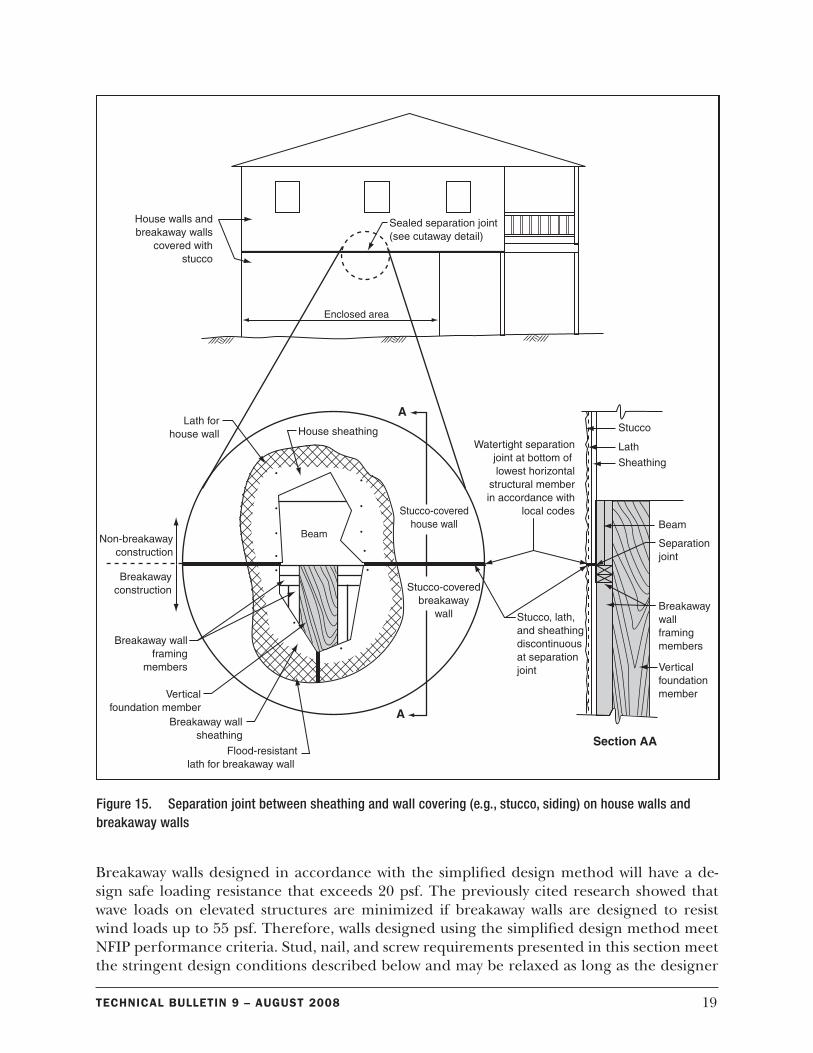
4. Breakaway wall sheathing and siding shall be discontinuous at elevated floor beams and joists; horizontal separation joints shall be provided to prevent damage to the sheathing or siding above the floor of the elevated building (see Figure 5). As shown in Figure 15, a watertight seal shall be provided for separation joints to prevent wind-driven rain water and sea spray from entering the building envelope. A similar vertical sealed joint may be needed in front of the piling.
5. Utilities, including electrical wiring, breaker boxes, power meters, plumbing, conduits, and ventilation ducts, shall not be placed in or attached to breakaway wall panels. Building supply lines and other utility fixtures, such as light switches or electrical outlets, may be attached to the sheltered side of vertical foundation members as allowed by applicable building codes and floodplain management regulations (which generally require that utilities be elevated above the BFE). If utility lines must be routed into or out of an enclosure, one or more of the walls shall be constructed with a utility blockout (see Figures 13 and 14). Utility lines that pass through the blockout shall be independent of the walls and therefore will not be damaged if the wall panels break away.
6. Breakaway wall panels shall be positioned such that, on failure, they do not collapse against cross-bracing or threaten other foundation components (for more information, see Techni-cal Bulletin 5).
7. Partial height breakaway wall systems are not permitted.
Prescriptive Design Method Example
Problem: Design a 10-foot wide by 9-foot tall wood-framed breakaway wall for a 3-second gust design wind speed of 110 mph. The Seismic Design Category is D, deflection of the wall is not important, and the wall is not within 4 feet of a building corner. Wood framing shall be con-structed using flood damage-resistant No. 2 Grade Spruce-Pine-Fir 2x4s.
Solution: The problem description clearly allows the use of the prescriptive design method. Figure 13 shows that 2x4 studs at 24 inches on center (o.c.) shall be toe nailed to the top and bottom plates using two 16d nails. According to Table 1b, twenty-four 10d nails (12 top and 12 bottom) can be used to connect the breakaway top and bottom plates to permanent 2x4 nailer plates.
Simplified Design Method for Breakaway Walls
In most coastal areas, the adopted building codes include wind and/or seismic design require-ments that exceed the 20 psf maximum limit allowed for breakaway walls that do not require certification by a registered design professional. NFIP performance criteria also allow for de-signs that meet these higher load requirements. Breakaway walls with allowable loads higher than 20 psf are permitted if a designer certifies that (1) the wall will collapse before base flood conditions are reached, and (2) the elevated building will not be damaged by combined wind and flood loads acting on all building components.
19Technical BulleTin 9 – auGuST 2008
Breakaway walls designed in accordance with the simplified design method will have a de-sign safe loading resistance that exceeds 20 psf. The previously cited research showed that wave loads on elevated structures are minimized if breakaway walls are designed to resist wind loads up to 55 psf. Therefore, walls designed using the simplified design method meet NFIP performance criteria. Stud, nail, and screw requirements presented in this section meet the stringent design conditions described below and may be relaxed as long as the designer
Figure 15. Separation joint between sheathing and wall covering (e.g., stucco, siding) on house walls and breakaway walls
20 Technical BulleTin 9 – auGuST 2008
ensures that the breakaway wall satisfies the governing code’s wind and/or seismic require-ments. Future research and testing on walls with design wind pressures significantly exceeding 55 psf may allow use of the simplified method where the 3-second gust design wind speed ex-ceeds 140 mph.
Applicability
The simplified design method for wood-framed and steel stud-framed breakaway walls does not require a design professional and is permitted to be used if all of the following conditions are satisfied:
1. Breakaway wall heights are between 6 and 9 feet, where piles, columns or piers are spaced between 8 and 12 feet apart (the performance-based method shall be used for situations that fall outside of these limitations).
2. The 3-second gust design wind speed is between 110 and 140 mph (see Figure 12).
3. The simplified design method is permitted for all Seismic Design Categories identified in ASCE 7-05.
4. Breakaway walls serving as backup for brick veneer or other material that may be damaged by excessive deflections shall not be designed using the simplified design method.
Design Methodology
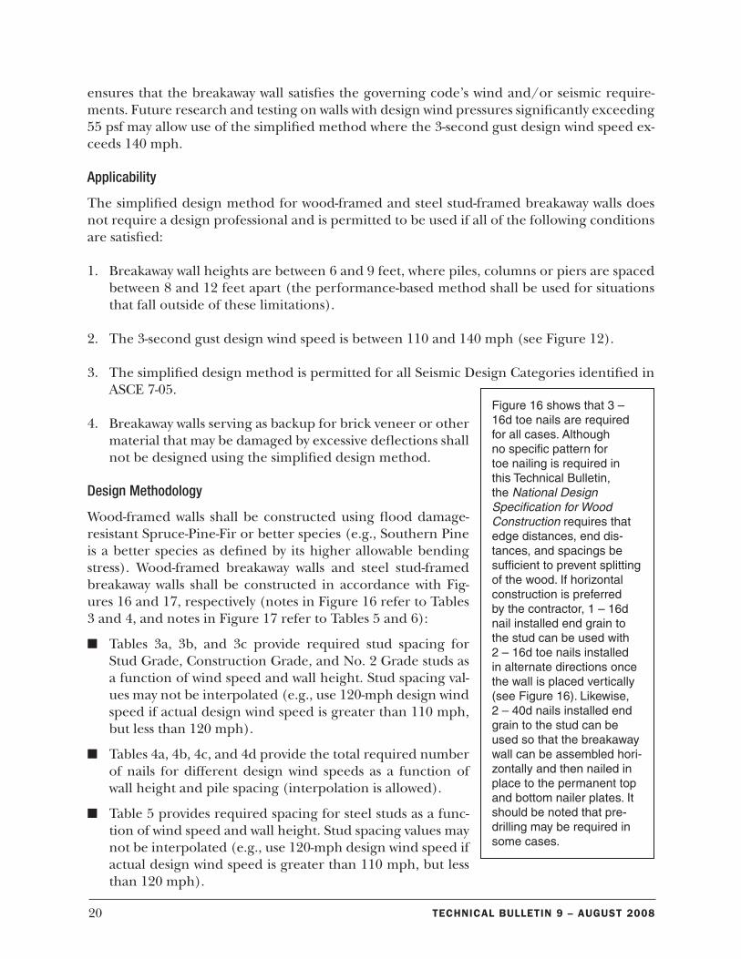
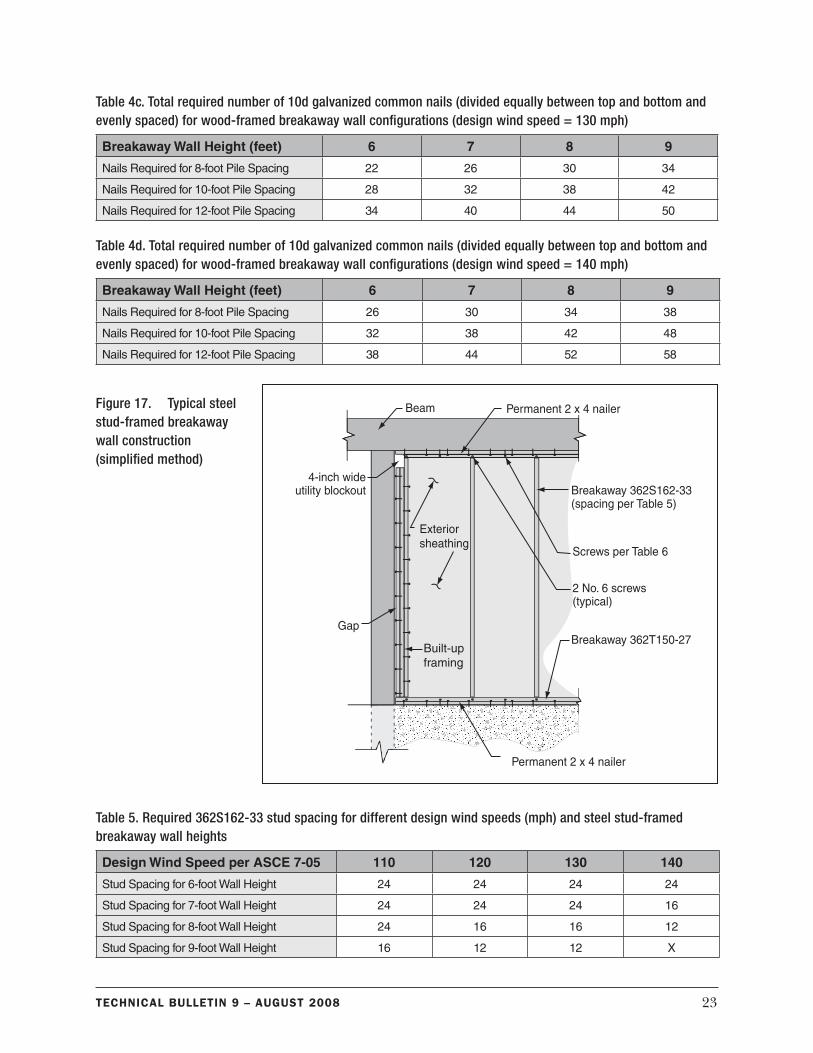
Wood-framed walls shall be constructed using flood damage-resistant Spruce-Pine-Fir or better species (e.g., Southern Pine is a better species as defined by its higher allowable bending stress). Wood-framed breakaway walls and steel stud-framed breakaway walls shall be constructed in accordance with Fig-ures 16 and 17, respectively (notes in Figure 16 refer to Tables 3 and 4, and notes in Figure 17 refer to Tables 5 and 6):
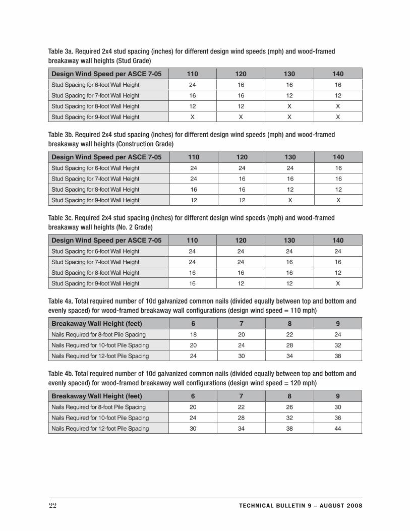
n Tables 3a, 3b, and 3c provide required stud spacing for Stud Grade, Construction Grade, and No. 2 Grade studs as a function of wind speed and wall height. Stud spacing val-ues may not be interpolated (e.g., use 120-mph design wind speed if actual design wind speed is greater than 110 mph, but less than 120 mph).
n Tables 4a, 4b, 4c, and 4d provide the total required number of nails for different design wind speeds as a function of wall height and pile spacing (interpolation is allowed).
n Table 5 provides required spacing for steel studs as a func-tion of wind speed and wall height. Stud spacing values may not be interpolated (e.g., use 120-mph design wind speed if actual design wind speed is greater than 110 mph, but less than 120 mph).
Figure 16 shows that 3 – 16d toe nails are required for all cases. Although no specific pattern for toe nailing is required in this Technical Bulletin, the National Design Specification for Wood Construction requires that edge distances, end dis-tances, and spacings be sufficient to prevent splitting of the wood. If horizontal construction is preferred by the contractor, 1 – 16d nail installed end grain to the stud can be used with 2 – 16d toe nails installed in alternate directions once the wall is placed vertically (see Figure 16). Likewise, 2 – 40d nails installed end grain to the stud can be used so that the breakaway wall can be assembled hori-zontally and then nailed in place to the permanent top and bottom nailer plates. It should be noted that pre-drilling may be required in some cases.
21Technical BulleTin 9 – auGuST 2008
n Tables 6a, 6b, 6c, and 6d provide the required number of self tapping screws for differ-ent design wind speeds as a function of wall height and pile spacing (interpolation is allowed).
Careful plan review and inspection by local jurisdictions is paramount when the simplified design method is used. Plan reviewers must ensure that the proper number and type of con-nectors are specified for both the top and the bottom plate connections, and inspectors should pay close attention that the installation complies with the approved plans.
In areas where design wind speeds are less than or equal to 140 mph, inspectors may accept more top and bottom connectors than are specified in Table 4 (for wood studs) and Table 6 (for steel studs). However, because breakaway walls fail near the ground, it is important that the number of bottom plate connectors not exceed one or two more than the number of con-nectors specified in Table 4d and Table 6d (regardless of design wind speed), or performance will be jeopardized.
Design Details
Design details described for the prescriptive design method in the previous section apply for the simplified design method (see page 17).
Figure 16. Typical wood-framed breakaway wall construction (simplified method)
22 Technical BulleTin 9 – auGuST 2008
Table 3a. Required 2x4 stud spacing (inches) for different design wind speeds (mph) and wood-framed breakaway wall heights (Stud Grade)
Design Wind Speed per ASCE 7-05 110 120 130 140
Stud Spacing for 6-foot Wall Height 24 16 16 16
Stud Spacing for 7-foot Wall Height 16 16 12 12
Stud Spacing for 8-foot Wall Height 12 12 X X
Stud Spacing for 9-foot Wall Height X X X X
Table 3b. Required 2x4 stud spacing (inches) for different design wind speeds (mph) and wood-framed breakaway wall heights (Construction Grade)
Design Wind Speed per ASCE 7-05 110 120 130 140
Stud Spacing for 6-foot Wall Height 24 24 24 16
Stud Spacing for 7-foot Wall Height 24 16 16 16
Stud Spacing for 8-foot Wall Height 16 16 12 12
Stud Spacing for 9-foot Wall Height 12 12 X X
Table 3c. Required 2x4 stud spacing (inches) for different design wind speeds (mph) and wood-framed breakaway wall heights (No. 2 Grade)
Design Wind Speed per ASCE 7-05 110 120 130 140
Stud Spacing for 6-foot Wall Height 24 24 24 24
Stud Spacing for 7-foot Wall Height 24 24 16 16
Stud Spacing for 8-foot Wall Height 16 16 16 12
Stud Spacing for 9-foot Wall Height 16 12 12 X
Table 4a. Total required number of 10d galvanized common nails (divided equally between top and bottom and evenly spaced) for wood-framed breakaway wall configurations (design wind speed = 110 mph)
Breakaway Wall Height (feet) 6 7 8 9
Nails Required for 8-foot Pile Spacing 18 20 22 24
Nails Required for 10-foot Pile Spacing 20 24 28 32
Nails Required for 12-foot Pile Spacing 24 30 34 38
Table 4b. Total required number of 10d galvanized common nails (divided equally between top and bottom and evenly spaced) for wood-framed breakaway wall configurations (design wind speed = 120 mph)
Breakaway Wall Height (feet) 6 7 8 9
Nails Required for 8-foot Pile Spacing 20 22 26 30
Nails Required for 10-foot Pile Spacing 24 28 32 36
Nails Required for 12-foot Pile Spacing 30 34 38 44
23Technical BulleTin 9 – auGuST 2008
Table 4c. Total required number of 10d galvanized common nails (divided equally between top and bottom and evenly spaced) for wood-framed breakaway wall configurations (design wind speed = 130 mph)
Breakaway Wall Height (feet) 6 7 8 9
Nails Required for 8-foot Pile Spacing 22 26 30 34
Nails Required for 10-foot Pile Spacing 28 32 38 42
Nails Required for 12-foot Pile Spacing 34 40 44 50
Table 4d. Total required number of 10d galvanized common nails (divided equally between top and bottom and evenly spaced) for wood-framed breakaway wall configurations (design wind speed = 140 mph)
Breakaway Wall Height (feet) 6 7 8 9
Nails Required for 8-foot Pile Spacing 26 30 34 38
Nails Required for 10-foot Pile Spacing 32 38 42 48
Nails Required for 12-foot Pile Spacing 38 44 52 58
Table 5. Required 362S162-33 stud spacing for different design wind speeds (mph) and steel stud-framed breakaway wall heights
Design Wind Speed per ASCE 7-05 110 120 130 140
Stud Spacing for 6-foot Wall Height 24 24 24 24
Stud Spacing for 7-foot Wall Height 24 24 24 16
Stud Spacing for 8-foot Wall Height 24 16 16 12
Stud Spacing for 9-foot Wall Height 16 12 12 X
Figure 17. Typical steel stud-framed breakaway wall construction (simplified method)
24 Technical BulleTin 9 – auGuST 2008
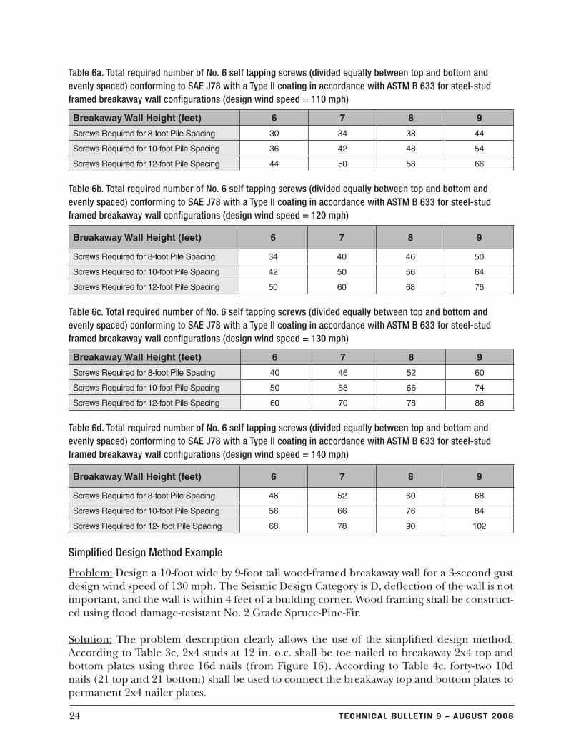
Table 6a. Total required number of No. 6 self tapping screws (divided equally between top and bottom and evenly spaced) conforming to SAE J78 with a Type II coating in accordance with ASTM B 633 for steel-stud framed breakaway wall configurations (design wind speed = 110 mph)
Breakaway Wall Height (feet) 6 7 8 9
Screws Required for 8-foot Pile Spacing 30 34 38 44
Screws Required for 10-foot Pile Spacing 36 42 48 54
Screws Required for 12-foot Pile Spacing 44 50 58 66
Table 6b. Total required number of No. 6 self tapping screws (divided equally between top and bottom and evenly spaced) conforming to SAE J78 with a Type II coating in accordance with ASTM B 633 for steel-stud framed breakaway wall configurations (design wind speed = 120 mph)
Breakaway Wall Height (feet) 6 7 8 9
Screws Required for 8-foot Pile Spacing 34 40 46 50
Screws Required for 10-foot Pile Spacing 42 50 56 64
Screws Required for 12-foot Pile Spacing 50 60 68 76
Table 6c. Total required number of No. 6 self tapping screws (divided equally between top and bottom and evenly spaced) conforming to SAE J78 with a Type II coating in accordance with ASTM B 633 for steel-stud framed breakaway wall configurations (design wind speed = 130 mph)
Breakaway Wall Height (feet) 6 7 8 9
Screws Required for 8-foot Pile Spacing 40 46 52 60
Screws Required for 10-foot Pile Spacing 50 58 66 74
Screws Required for 12-foot Pile Spacing 60 70 78 88
Table 6d. Total required number of No. 6 self tapping screws (divided equally between top and bottom and evenly spaced) conforming to SAE J78 with a Type II coating in accordance with ASTM B 633 for steel-stud framed breakaway wall configurations (design wind speed = 140 mph)
Breakaway Wall Height (feet) 6 7 8 9
Screws Required for 8-foot Pile Spacing 46 52 60 68
Screws Required for 10-foot Pile Spacing 56 66 76 84
Screws Required for 12- foot Pile Spacing 68 78 90 102
Simplified Design Method Example
Problem: Design a 10-foot wide by 9-foot tall wood-framed breakaway wall for a 3-second gust design wind speed of 130 mph. The Seismic Design Category is D, deflection of the wall is not important, and the wall is within 4 feet of a building corner. Wood framing shall be construct-ed using flood damage-resistant No. 2 Grade Spruce-Pine-Fir.
Solution: The problem description clearly allows the use of the simplified design method. According to Table 3c, 2x4 studs at 12 in. o.c. shall be toe nailed to breakaway 2x4 top and bottom plates using three 16d nails (from Figure 16). According to Table 4c, forty-two 10d nails (21 top and 21 bottom) shall be used to connect the breakaway top and bottom plates to permanent 2x4 nailer plates.
25Technical BulleTin 9 – auGuST 2008
As explained in the section on design methodology (see page 21), because this example is in an area with a design wind speed of less than or equal to 140 mph, additional top and bot-tom connectors may be used and accepted by inspectors. However, to allow the wall to break away as intended, inspectors should not accept more than the number of bottom connectors specified in Table 4d (plus an additional one or two). Therefore, while the solution indicated by Table 4c requires 21 nails at the top plate and 21 nails at the bottom plate, the maximum number that inspectors should accept for the bottom plate is 26 nails (per Table 4d, 24 nails plus not more than two extra nails).
Performance-Based Design of Breakaway Walls
Breakaway walls designed in accordance with the performance-based design method will nor-mally have an allowable load of more than 20 psf. Flood loads (i.e., wave loads, hydrodynamic loads, and impact loads) on breakaway walls must be calculated and taken into account when designing the elevated structure and the foundation system. However, as described below, the designer is given slightly more freedom when detailing breakaway wall systems.
Applicability
Performance-based design of breakaway walls must be performed by a design professional. This method is always permitted and these walls may be designed and constructed using wood studs, steel-studs, unreinforced masonry, or alternative materials. However, it is anticipated that performance-based design will be used primarily when the applicability criteria (e.g., taller walls, wider spans, higher design wind speeds) for the prescriptive and simplified design methods cannot be satisfied.
Design Methodology
Performance-based design of breakaway walls consists of designing the breakaway wall to resist the largest out-of-plane load of (a) the design wind pressure in accordance with ASCE 7-05, (b) the design seismic out-of-plane load in accordance with ASCE 7-05, or (c) 10 psf. Although breakaway walls are permitted by NFIP regulations, the effects of flood loads on these walls (and any other building components that are below the BFE) must be included in the design of the elevated structure and its foundation. It should be noted that more resistant breakaway walls increase the potential forces from debris impact loading on foundation elements and possibly on neighboring structures.
Design Details
All breakaway walls designed using the performance-based design method shall be detailed in accordance with the following:
1. Breakaway walls shall be designed to meet all applicable local requirements and building code requirements.
2. Breakaway wall sheathing and siding shall be discontinuous at elevated floor beams and joists; horizontal separation joints shall be provided to prevent damage to the sheathing or siding above the floor of the elevated building (see Figure 5). As shown in Figure 15, a watertight seal shall be provided for separation joints to prevent wind-driven rain water
26 Technical BulleTin 9 – auGuST 2008
and sea spray from entering the building envelope. A similar vertical sealed joint may be needed in front of the piling.
3. Utilities, including electrical wiring, breaker boxes, power meters, plumbing, conduits, and ventilation ducts, shall not be placed in or attached to breakaway wall panels. Building supply lines and other utility fixtures, such as light switches or electrical outlets, may be attached to the sheltered side of vertical foundation members as allowed by applicable building codes and floodplain management regulations (which generally require that utilities be elevated above the BFE). If utility lines must be routed into or out of an enclosure, one or more of the walls shall be constructed with a utility blockout (see Figures 13 and 14). Utility lines that pass through the blockout shall be independent of the walls and therefore will not be damaged if the wall panels break away.
4. Breakaway wall panels shall be positioned such that, on failure, they do not collapse against cross-bracing or threaten other foundation components (for more information, see Techni-cal Bulletin 5).
5. Partial height breakaway wall systems are not permitted.
When using the performance-based design method, wood-framed and steel stud-framed breakaway wall panels may be attached to pilings or other vertical foundation members (i.e., all four sides of the panel may be attached) as accounted for in the design of the wall and foundation elements.
Unreinforced, ungrouted hollow-cell masonry units may be attached to floor beams and to concrete or masonry vertical foundation members with standard mortars and minimum pe-rimeter connections, as accounted for in the design of the wall and foundation elements. Continuous breakaway wall systems that span across pilings are not permitted.
Impact of Breakaway Wall Provisions on Other Building Elements
The NFIP requirements for breakaway walls have direct impacts on the other building ele-ments described in this section.
Utilities
Utilities and attendant equipment shall not be mounted on, pass through, or be located along breakaway walls. Where utilities and attendant equipment (e.g., lighting circuits, switches, re-ceptacles) are required to be installed below the BFE to address life safety and electric code requirements, they shall be mounted on the sheltered (i.e., landward) side of foundation members. If utility lines must be routed into or out of an enclosure, one or more of the walls shall be constructed with a utility blockout. Utility lines that pass through the blockout shall be independent of the walls and therefore will not be damaged if the wall panels break away.
Garage Doors
Garage doors installed in enclosures with breakaway walls are not exempt from the NFIP re-quirements to break away under flood conditions. Standard residential garage doors may be
27Technical BulleTin 9 – auGuST 2008
considered breakaway panels and flood loads acting on these doors need not be considered. Although such doors have not been tested under wave loads, the IRC requires the use of doors that have been tested for wind loads. Experience has shown that these doors fail under very low wave loading that will not significantly affect the elevated home or foundation. Garage doors may be designed and detailed using the performance-based design provisions described in this Technical Bulletin.
Partial-Height Breakaway Wall Systems
Partial-height breakaway walls do not satisfy the NFIP requirements and are not permitted. These walls are constructed so that the bottom portion of the wall breaks away while the top portion of the wall (above the BFE but below the elevated structure) is strengthened to survive the design event. The NFIP regulations specifically state that walls below the lowest floor of an elevated building shall be breakaway walls.
Exterior Façade
Exterior façade treatments such as brick veneer, concrete plank, stucco, or other unrein-forced nonstructural elements may be attached to breakaway walls provided the façade does not inhibit the breakaway characteristics of the walls. Façade connections shall be designed and detailed to meet building code requirements for wind and seismic loading. Horizontal separation joints shall be used at the elevated floor level to minimize damage to the elevated structure.
Interior Finishes
Enclosures below elevated buildings are allowed only for parking of vehicles, building access, or storage. Installing utility stub-outs (i.e., purposely placed utility access points for future connections) is inconsistent with the allowable uses of an unfinished enclosed area. Likewise, finishing the interior of enclosures with drywall or other finish materials is not permitted un-less required to address life-safety and fire code requirements. An exception exists for steel stud-framed breakaway walls, where structural performance under wind loads requires con-tinuous lateral bracing of both stud flanges.
Construction Materials
The NFIP requires that construction materials used below the BFE be resistant to flood dam-age. Flood damage-resistant materials are those that are capable of withstanding direct and prolonged contact (i.e., at least 72 hours) with floodwaters without suffering significant dam-age (i.e., damage requiring more than reasonable cleanup or low-cost cosmetic repair, such as painting). More details are found in Technical Bulletin 2, Flood Damage-Resistant Materials Requirements for Buildings Located in Special Flood Hazard Areas.
Unless other materials are required to address life safety and fire code requirements, flood damage-resistant materials shall be used for breakaway walls and wall panels, as outlined be-low.
28 Technical BulleTin 9 – auGuST 2008
Wood-Frame Materials n All lumber shall be preservative-treated or decay-resistant (e.g., redwood, cedar, some
oaks, and bald cypress).
n Exterior siding shall be exterior grade and no thicker than ½-inch plywood, APA 32/16 rated sheathing or other equivalent sheathing material.
n Wall studs shall be no larger than 2 inches x 4 inches (nominal dimensions) unless designed using the performance-based design provisions described in this Technical Bulletin.
n Interior wall sheathing shall not be permitted.
Metal Connectorsn Metal connectors shall be corrosion-resistant (see Technical Bulletin 8, Corrosion Protection
for Metal Connectors in Coastal Areas).
Other Materials n Light-gauge steel framing, such as steel studs, shall be coated to resist corrosion.
n Stucco, Exterior Insulation Finishing System (EIFS) walls, and other lightweight exterior sheathing material may be applied, as long as a separation joint is provided where the material is attached at or near the bottom of the elevated floor beam or joists (see Fig-ure 15). Insulation shall also be installed with a separation joint so that it does not hinder performance.
n Foam sheathed walls may be designed and used as breakaway walls in accordance with the performance-based design provisions presented in this Technical Bulletin.
Existing Buildings: Repairs, Remodeling, Additions, and Retrofitting
Work that is determined to be substantial improvement of an existing building (including additions and repairs of substantial damage) must comply with the NFIP regulations and the entire structure must also be brought into compliance. Work on any existing building that was constructed in compliance with the NFIP requirements must comply with the requirements and not jeopardize the continued compliance of the building. Therefore, if enclosures are added below compliant buildings, breakaway walls shall be used. For more information about requirements for substantially improved and substantially damaged buildings, see Answers to Questions About Substantially Damaged Buildings (FEMA 213).
Recommendations for Coastal A Zones
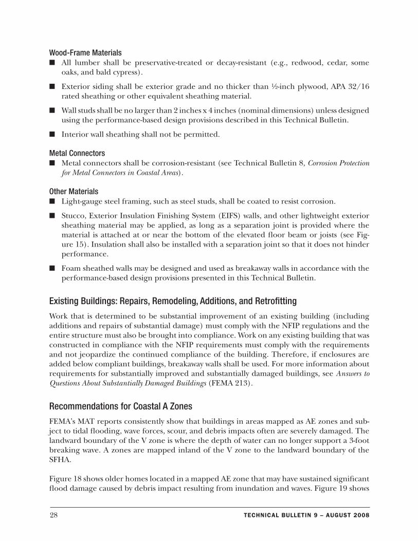
FEMA’s MAT reports consistently show that buildings in areas mapped as AE zones and sub-ject to tidal flooding, wave forces, scour, and debris impacts often are severely damaged. The landward boundary of the V zone is where the depth of water can no longer support a 3-foot breaking wave. A zones are mapped inland of the V zone to the landward boundary of the SFHA.
Figure 18 shows older homes located in a mapped AE zone that may have sustained significant flood damage caused by debris impact resulting from inundation and waves. Figure 19 shows
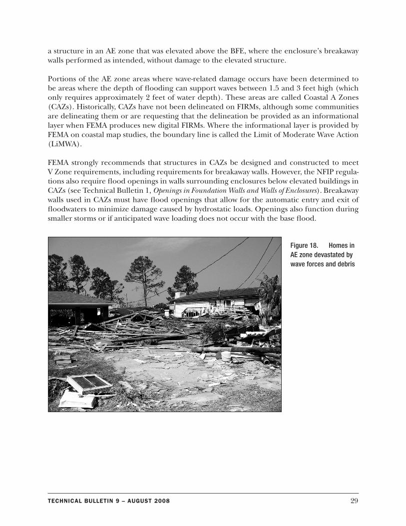
29Technical BulleTin 9 – auGuST 2008
a structure in an AE zone that was elevated above the BFE, where the enclosure’s breakaway walls performed as intended, without damage to the elevated structure.
Portions of the AE zone areas where wave-related damage occurs have been determined to be areas where the depth of flooding can support waves between 1.5 and 3 feet high (which only requires approximately 2 feet of water depth). These areas are called Coastal A Zones (CAZs). Historically, CAZs have not been delineated on FIRMs, although some communities are delineating them or are requesting that the delineation be provided as an informational layer when FEMA produces new digital FIRMs. Where the informational layer is provided by FEMA on coastal map studies, the boundary line is called the Limit of Moderate Wave Action (LiMWA).
FEMA strongly recommends that structures in CAZs be designed and constructed to meet V Zone requirements, including requirements for breakaway walls. However, the NFIP regula-tions also require flood openings in walls surrounding enclosures below elevated buildings in CAZs (see Technical Bulletin 1, Openings in Foundation Walls and Walls of Enclosures). Breakaway walls used in CAZs must have flood openings that allow for the automatic entry and exit of floodwaters to minimize damage caused by hydrostatic loads. Openings also function during smaller storms or if anticipated wave loading does not occur with the base flood.
Figure 18. Homes in AE zone devastated by wave forces and debris
30 Technical BulleTin 9 – auGuST 2008
The NFIP
The U.S. Congress established the NFIP with the passage of the National Flood Insurance Act of 1968. The NFIP is a Federal program enabling property owners in participating com-munities to purchase insurance as protection against flood losses, in exchange for State and community floodplain management regulations that reduce future flood damages. Participa-tion in the NFIP is based on an agreement between communities and the Federal Government. If a community adopts and enforces adequate floodplain management regulations, FEMA will make flood insurance available within the community.
Title 44 of the U.S. Code of Federal Regulations contains the NFIP criteria for floodplain man-agement, including design and construction standards for new and substantially improved buildings located in SFHAs identified on the NFIP’s FIRMs. FEMA encourages communities to adopt floodplain management regulations that exceed the minimum NFIP criteria. As an insurance alternative to disaster assistance, the NFIP reduces the escalating costs of repairing damage to buildings and their contents caused by floods.
NFIP Technical Bulletins
This is one of a series of Technical Bulletins that FEMA has produced to provide guidance concerning the building performance requirements of the NFIP. These requirements are con-tained in Title 44 of the U.S. Code of Federal Regulations at Section 60.3. The bulletins are intended for use by State and local officials responsible for interpreting and enforcing the requirements in their floodplain management regulations and building codes, and by mem-bers of the development community, such as design professionals and builders. New bulletins, as well as updates of existing bulletins, are issued periodically, as necessary. The bulletins do not create regulations; rather, they provide specific guidance for complying with the require-ments of existing NFIP regulations. Users of the Technical Bulletins who need additional
Figure 19. Structure elevated above BFE in AE zone showing successful response of breakaway walls
31Technical BulleTin 9 – auGuST 2008
guidance should contact their NFIP State Coordinator or the appropriate FEMA regional office. FEMA’s User’s Guide to Technical Bulletins (http://www.fema.gov/pdf/fima/guide01.pdf) lists the bulletins issued to date.
Ordering Technical Bulletins
The quickest and easiest way to acquire copies of FEMA’s Technical Bulletins is to down-load them from the FEMA website (http://www.fema.gov/plan/prevent/floodplain/techbul.shtm).
Technical Bulletins also may be ordered free of charge from the FEMA Publications Ware-house by calling 1-800-480-2520, or by faxing a request to 301-362-5355, Monday through Friday between 8 a.m. and 5 p.m. EST. Please provide the FEMA publication number, title, and quantity of each publication requested, along with your name, address, zip code, and day-time telephone number. Written requests may be also be submitted by mail to the following address:
FEMA Publications P.O. Box 2012 Jessup, MD 20794
Further Information
The following sources provide further information concerning breakaway walls below elevat-ed coastal buildings.
American Forest & Paper Association/American Wood Council, 2005, NDS: National Design Specification for Wood Construction.
American Society of Civil Engineers, Structural Engineering Institute. 2005. Flood Resistant Design and Construction, ASCE 24-05.
American Society of Civil Engineers, Structural Engineering Institute. 2005. Minimum Design Loads for Buildings and Other Structures, ASCE 7-05.
FEMA. 1991. Answers to Questions About Substantially Damaged Buildings. FEMA 213.
FEMA. 2000. Coastal Construction Manual, FEMA 55CD (3rd edition).
FEMA. 2005. FEMA 499: Home Builder’s Guide to Coastal Construction Technical Fact Sheet Series.
FEMA. 2008. NFIP Technical Bulletin 1-08. Openings in Foundation Walls and Walls of Enclo-sures.
32 Technical BulleTin 9 – auGuST 2008
FEMA. 2008. NFIP Technical Bulletin 2-08. Flood Damage-Resistant Materials Requirements.
FEMA. 2008. NFIP Technical Bulletin 5-08. Free-of-Obstruction Requirements.
FEMA. 1996. NFIP Technical Bulletin 8-96. Corrosion Protection for Metal Connectors in Coastal Areas.
International Code Council, Inc., 2006. International Building Code®, IBC 2006.
International Code Council, Inc., 2006. International Residential Code®, IRC 2006.
Rogers, Spencer M. 1991. Foundations and Breakaway Walls of Small Coastal Buildings in Hurri-cane Hugo. Proceedings of Coastal Zone ‘91. American Society of Civil Engineers. New York, NY.
Tung, C.C.; Bohumil Kasal; Spencer M. Rogers, Jr.; S.C. Yeh. 1999. Behavior of Breakaway Wall Subjected to Wave Forces: Analytical and Experimental Studies. North Carolina Sea Grant, North Carolina State University. Raleigh, NC.
Glossary
Base flood — The flood having a 1- percent chance of being equaled or exceeded in any given year; commonly referred to as the “100-year flood.” The base flood is the national standard used by the NFIP and all Federal agencies for the purposes of requiring the purchase of flood insurance and regulating new development.
Base flood elevation (BFE) — The height of the base (1- percent annual chance or 100-year) flood in relation to the specified datum on the community's flood hazard map, usually the National Geodetic Vertical Datum of 1929 (NGVD), or the North American Vertical Datum of 1988 (NAVD).
Breakaway wall — A wall that is not part of the structural support of the building and is in-tended through its design and construction to collapse under specified lateral loading forces, without causing damage to the elevated portion of the building or supporting foundation sys-tem.
Coastal A Zone — An area within a special flood hazard area, landward of a V zone or land-ward of an open coast without mapped V zones; in a Coastal A Zone, the principal source of flooding must be astronomical tides, storm surges, seiches, or tsunamis, not riverine flooding. During the base flood conditions, the potential for wave heights shall be greater than or equal to 1.5 feet. Coastal A Zones are not normally designated on FIRMs.
Coastal High Hazard Area — An area of special flood hazard extending from offshore to the inland limit of a primary frontal dune along an open coast and any other area subject to high-velocity wave action from storms or seismic sources.
33Technical BulleTin 9 – auGuST 2008
Detailing — The design practice of using structural and architectural drawings and specifica-tions to arrange, configure, and connect structural and nonstructural building components of a building system. Design details convey to the contractor exactly how the structural and nonstructural components of a building should be built.
Federal Emergency Management Agency (FEMA) — The Federal agency that, in addition to carrying out other activities, administers the National Flood Insurance Program.
Flood Insurance Rate Map (FIRM) — The official map of a community on which FEMA has delineated both the Special Flood Hazard Areas (SFHAs) and the risk premium zones appli-cable to the community.
Hydrodynamic load — The load imposed on an immersed object, such as a foundation element or enclosure wall, by water flowing against and around it. The magnitude of the hy-drodynamic load varies as a function of velocity and other factors.
Hydrostatic load — The load imposed on an immersed object such as an enclosure wall, by standing or slowly moving water. The magnitude of the hydrostatic load increases linearly with water depth.
Limit of Moderate Wave Action (LiMWA) — The boundary line given by FEMA on coastal map studies marking the extents of Coastal A Zones.
Lowest floor — The lowest floor of the lowest enclosed area of a building, including a base-ment. Any NFIP-compliant, unfinished or flood-resistant enclosure usable solely for parking of vehicles, building access, or storage (in an area other than a basement) is not considered a building’s lowest floor, provided the enclosure does not render the structure in violation of the applicable design requirements of the NFIP.
Mitigation Directorate — The component of FEMA directly responsible for administering the flood hazard identification and floodplain management aspects of the NFIP.
New construction— For floodplain management purposes, new construction means structures for which the start of construction commences on or after the effective date of a floodplain management regulation adopted by a community and includes subsequent improvements to the structure.
Registered Design Professional — An individual who is registered or licensed to practice their respective design profession as defined by the statutory requirements of the professional reg-istration laws of the State or jurisdiction in which the project is to be constructed.
Special Flood Hazard Area (SFHA) — An area delineated on a FIRM as being subject to inun-dation by the base flood.
Standard residential garage door — A door, typically up to 18 feet wide by up to 8 feet tall, intended for use in a residential garage for vehicular access and normally expected to be op-erated less than 1,500 cycles per year.
34 Technical BulleTin 9 – auGuST 2008
Substantial damage — Damage of any origin sustained by a structure whereby the cost of re-storing the structure to its before-damaged condition would equal or exceed 50 percent of the market value of the structure before the damage occurred. Structures that are determined to be substantially damaged are considered to be substantial improvements, regardless of the actual repair work performed.
Substantial improvement — Any reconstruction, rehabilitation, addition, or other improve-ment of a structure, the cost of which equals or exceeds 50 percent of the market value of the structure (or smaller percentage if established by the community) before the “start of con-struction” of the improvement. This term includes structures that have incurred “substantial damage,” regardless of the actual repair work performed.


![INDEX [] · iso 5675 push pull coupling ( with bulkhead) push pull agri series 71 8 iso 5675 breakaway coupling breakaway series 73 iso 5675 breakaway coupling (with male end ) breakaway](https://img.pdfslide.net/doc/110x75/5c168d0809d3f29f108cc8b6/index-iso-5675-push-pull-coupling-with-bulkhead-push-pull-agri-series.jpg)