Embed Size (px)
Citation preview
Design and Moldflow Analysis of Piston Cooling Nozzle in Automobiles
V. Ganeshram1* and M. Achudhan2
1Assistant Professor, Department of Mechanical Engineering, Bharath University, Chennai-600073; [email protected]
2Associate Professor, Department of Mechanical Engineering, Bharath University, Chennai-600073; [email protected]
AbstractAutomobile industries have shown great interest in replacing metal to plastic parts in order to reduce the cost and weight of the components. This can be achieved mostly be replacing metal component with injection molded components. Our study deals with the use of mold flow simulation in as a case study of metal to plastic conversion of the automobile compo-nent piston cooling nozzle. In this context the aluminium piston cooling nozzle is replaced by Nylon66+30GF piston cooling nozzle. Then based on the final product design, hand injection mold of the component was designed and manufactured. Finally the plastic part has to be tested for the working conditions, its performance in usage and compared with the alu-minium part.
Keywords: Metal to Plastic, Finite Element Analysis, Piston Cooling Nozzle.
1. IntroductionThe current trend in the automobile industry is towards increase in the power density of the engine and making lighter engines. These requirements lead to a higher ther-mal load on the engine especially on the pistons. Piston cooling nozzle is located in the cylinder of an engine. Its main function is to cool the piston by spraying the cool-ant through the nozzle of this piston cooling device in order to avoid overheating. The aluminium piston cooling nozzle is manufactured by castings followed by second-ary operations for drilling holes which leads to increase in production time. This can be reduced by using plastic as replacement of the metal apart from the weight and cost reduction [1]. The suitable plastic material is selected for flow simulation as per the working conditions of the prod-uct. The increase in the piston temperature causes cavity edge cracking due to an increase in the thermal load and reduction in material strength, in the case of aluminium
alloy pistons. An excessive temperature of the piston results in piston scuffing increased blow by owing to sticking of the piston rings to grooves and an increased oil consump-tion caused by wear of piston rings and ring grooves. These in turn decrease the reliability and durability of the engine significantly. Therefore, the control of piston temperature by piston cooling becomes important. There are basically two approaches to cope with the increase in the thermal load of pistons [2]. One is the improvement in piston cool-ing ability through redesign of the piston structure. The other is improvement of material strength in the high tem-perature region.
2. DescriptionPiston cooling nozzle used in automobiles is made up of metals like steel, aluminium. It is manufactured by die casting process. This is replaced by plastics material
* Corresponding author:V. Ganeshram ([email protected])
Indian Journal of Science and Technology
Supplementary Article
V. Ganeshram and M. Achudhan 4809
Indian Journal of Science and Technology | Print ISSN: 0974-6846 | Online ISSN: 0974-5645www.indjst.org | Vol 6 (6S) | May 2013
Nylon66+30GF which are manufactured by injection mold-ing process [3]. Its overall thickness is 3mm. Some problems of using this aluminium device is such that it leads to some secondary operations for drilling holes which leads to increase in production time. This can be reduced by using injection molded plastic part as a solution. The bound-ary conditions for the piston cooling device are found out as: (1) nozzle opening pressure: 1.6±0.3/-0.2 bar oil pres-sure. (2) Operating temperature: 120°C (3). Flow pressure: 3.1 bar oil pressure. Selection of material is a highly complex process. It involves the primary considerations in selecting a material for a specific application such as function and cost. The functional requirements of the part are heat with-stand ability, oil pressure withstanding capacity, mounting, design flexibility [4]. The selection criteria of the material are based on the following thermal properties of the mate-rial such as Heat deflection temperature (HDT) at 1.8MPa stress and continuous service temperature.
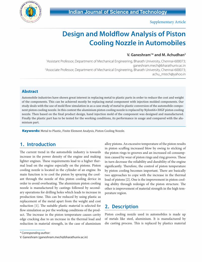
3. ExperimentThe modeling of the component is done by using the design software proe Figure 1. Small holes are important because it increases the pressure of oil flow.
Finite element analysis is a computer based numerical technique for calculating the strength and behavior of engi-neering structures. It can be used to calculate deflection, stress, vibration, buckling behavior and many other phenomena. It can be used to analyze either small or large scale deflection under loading or applied displacement. It can analyze elastic deformation or permanently bent out of shape plastics deformation [5]. The power and low cost of modern computers has made finite element analysis available to many disciplines and companies. The structure is broken down into many small simple blocks or elements.
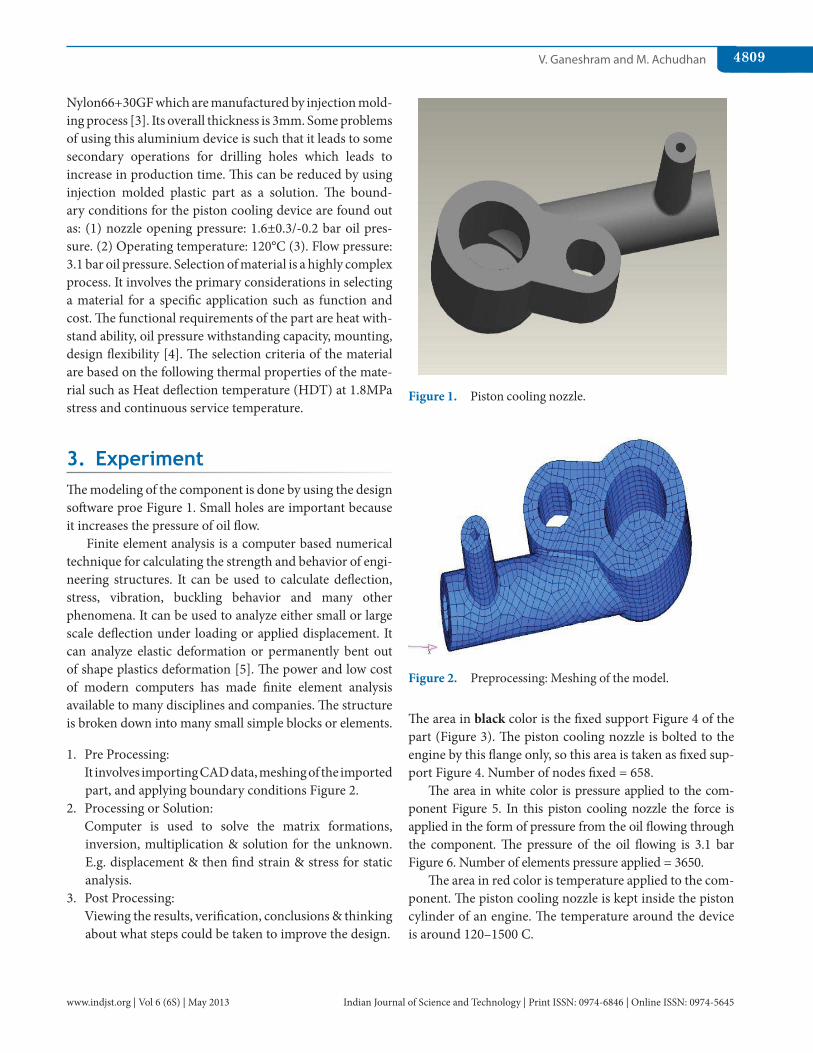
1. Pre Processing: It involves importing CAD data, meshing of the imported
part, and applying boundary conditions Figure 2.2. Processing or Solution: Computer is used to solve the matrix formations,
inversion, multiplication & solution for the unknown. E.g. displacement & then find strain & stress for static analysis.
3. Post Processing: Viewing the results, verification, conclusions & thinking
about what steps could be taken to improve the design.
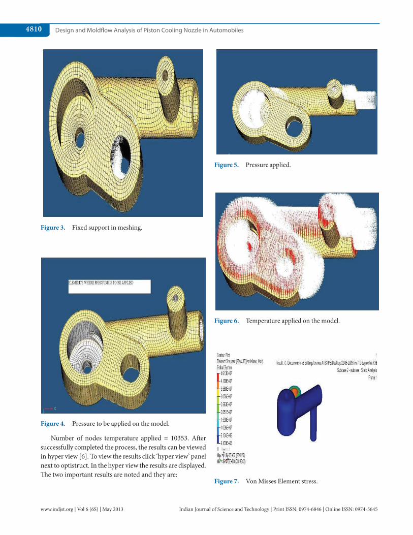
The area in black color is the fixed support Figure 4 of the part (Figure 3). The piston cooling nozzle is bolted to the engine by this flange only, so this area is taken as fixed sup-port Figure 4. Number of nodes fixed = 658.
The area in white color is pressure applied to the com-ponent Figure 5. In this piston cooling nozzle the force is applied in the form of pressure from the oil flowing through the component. The pressure of the oil flowing is 3.1 bar Figure 6. Number of elements pressure applied = 3650.
The area in red color is temperature applied to the com-ponent. The piston cooling nozzle is kept inside the piston cylinder of an engine. The temperature around the device is around 120–1500 C.
Figure 1. Piston cooling nozzle.
Figure 2. Preprocessing: Meshing of the model.
Design and Moldflow Analysis of Piston Cooling Nozzle in Automobiles4810
Indian Journal of Science and Technology | Print ISSN: 0974-6846 | Online ISSN: 0974-5645www.indjst.org | Vol 6 (6S) | May 2013
Number of nodes temperature applied = 10353. After successfully completed the process, the results can be viewed in hyper view [6]. To view the results click ‘hyper view’ panel next to optistruct. In the hyper view the results are displayed. The two important results are noted and they are:
Figure 3. Fixed support in meshing.
Figure 4. Pressure to be applied on the model.
Figure 5. Pressure applied.
Figure 6. Temperature applied on the model.
Figure 7. Von Misses Element stress.
V. Ganeshram and M. Achudhan 4811
Indian Journal of Science and Technology | Print ISSN: 0974-6846 | Online ISSN: 0974-5645www.indjst.org | Vol 6 (6S) | May 2013
• Vonmiseselementalstress• Displacement
4. OptimizationAnalyzing the performance of structures is usually only the first step for engineers. More often than not, they are called upon to make proposals on where and how to modify a part in order to meet stress, weight or stiffness requirements.
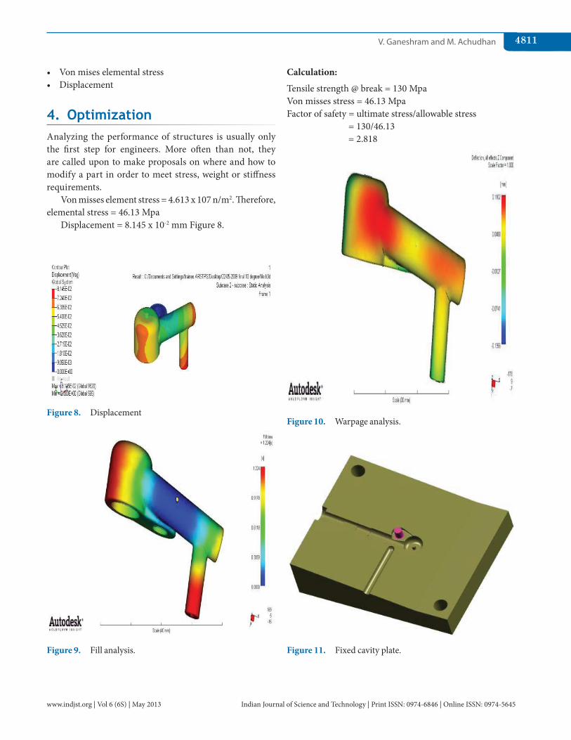
Von misses element stress = 4.613 x 10⁷ n/m2. Therefore, elemental stress = 46.13 Mpa
Displacement = 8.145 x 10⁻² mm Figure 8.
Calculation:
Tensile strength @ break = 130 Mpa Von misses stress = 46.13 Mpa Factor of safety = ultimate stress/allowable stress
= 130/46.13 = 2.818
Figure 8. Displacement
Figure 9. Fill analysis.
Figure 10. Warpage analysis.
Figure 11. Fixed cavity plate.
Design and Moldflow Analysis of Piston Cooling Nozzle in Automobiles4812
Indian Journal of Science and Technology | Print ISSN: 0974-6846 | Online ISSN: 0974-5645www.indjst.org | Vol 6 (6S) | May 2013
Factor of safety is more than 2, therefore the design is safe.
The mold flow analysis is a finite element volume method (FVM) based upon computer based numerical technique for validate complex engineering problem.
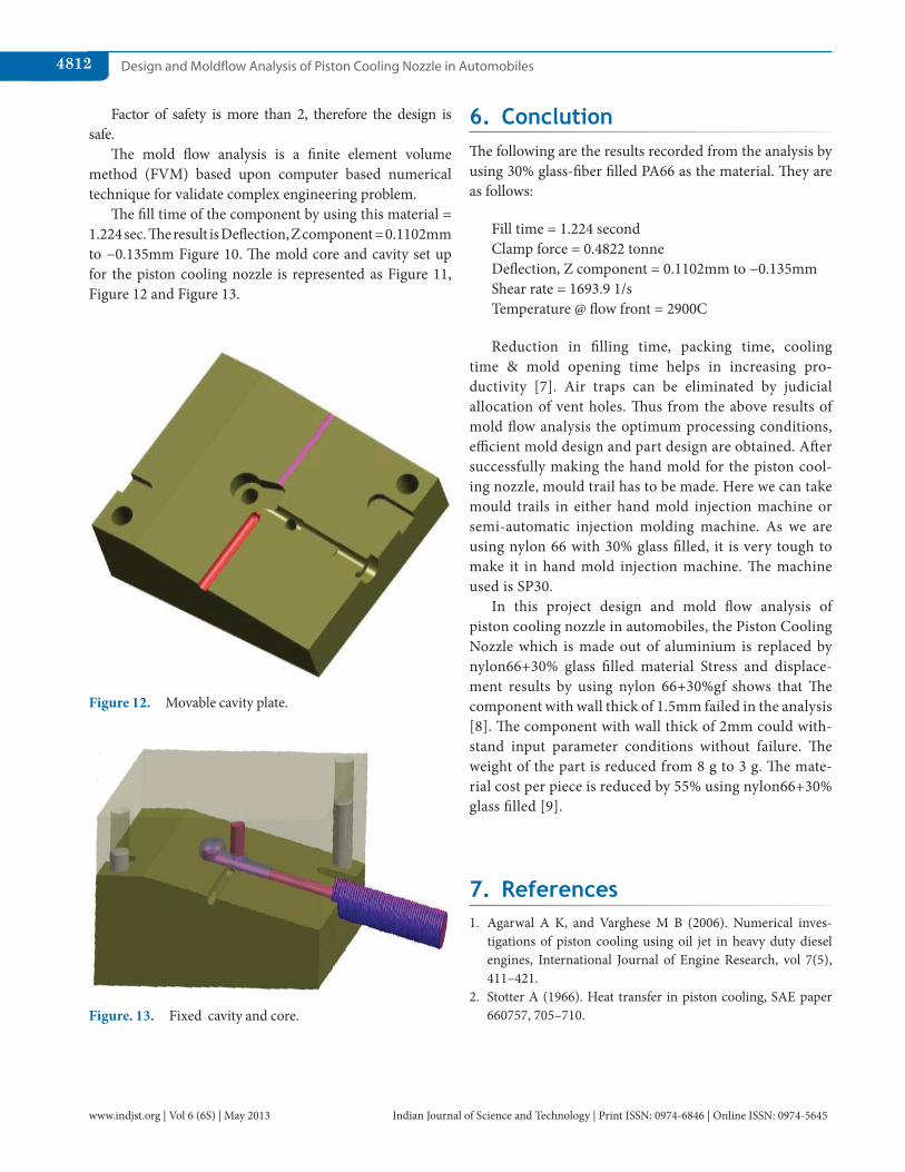
The fill time of the component by using this material = 1.224 sec. The result is Deflection, Z component = 0.1102mm to −0.135mm Figure 10. The mold core and cavity set up for the piston cooling nozzle is represented as Figure 11, Figure 12 and Figure 13.
6. ConclutionThe following are the results recorded from the analysis by using 30% glass-fiber filled PA66 as the material. They are as follows:
Fill time = 1.224 second Clamp force = 0.4822 tonne Deflection, Z component = 0.1102mm to −0.135mm Shear rate = 1693.9 1/s Temperature @ flow front = 2900C
Reduction in filling time, packing time, cooling time & mold opening time helps in increasing pro-ductivity [7]. Air traps can be eliminated by judicial allocation of vent holes. Thus from the above results of mold flow analysis the optimum processing conditions, efficient mold design and part design are obtained. After successfully making the hand mold for the piston cool-ing nozzle, mould trail has to be made. Here we can take mould trails in either hand mold injection machine or semi-automatic injection molding machine. As we are using nylon 66 with 30% glass filled, it is very tough to make it in hand mold injection machine. The machine used is SP30.
In this project design and mold flow analysis of piston cooling nozzle in automobiles, the Piston Cooling Nozzle which is made out of aluminium is replaced by nylon66+30% glass filled material Stress and displace-ment results by using nylon 66+30%gf shows that The component with wall thick of 1.5mm failed in the analysis [8]. The component with wall thick of 2mm could with-stand input parameter conditions without failure. The weight of the part is reduced from 8 g to 3 g. The mate-rial cost per piece is reduced by 55% using nylon66+30% glass filled [9].
7. References1. Agarwal A K, and Varghese M B (2006). Numerical inves-
tigations of piston cooling using oil jet in heavy duty diesel engines, International Journal of Engine Research, vol 7(5), 411–421.
2. Stotter A (1966). Heat transfer in piston cooling, SAE paper 660757, 705–710.
Figure 12. Movable cavity plate.
Figure. 13. Fixed cavity and core.

V. Ganeshram and M. Achudhan 4813
Indian Journal of Science and Technology | Print ISSN: 0974-6846 | Online ISSN: 0974-5645www.indjst.org | Vol 6 (6S) | May 2013
3. Lee R T (1990). Piston cooling nozzle, US patent no: 4979473. 4. Kajiwara H, Fujioka Y et al. (2002). An analytical approach for
prediction of piston temperature distribution in diesel engines JSAE review, vol 23(4), 429–434.
5. Dimla D E, Camilotto M et al. (2005). Design and optimization of conformal cooling channels in injection molding tools, Journal of Materials & Processing Technology, vol 164–165, 1294–1300.
6. Bamkin R J, and Piearcey B J (1990). Knowledge-based material selection in design , Materials & Design, vol 11(1), 25–29.
7. Wu J, Ruichong R et al. (2002). Vibration analysis of medi-cal devices with a calibrated FEA model, Computer and Structures, vol 80(12), 1081–1086.
8. Zienkiewicz O C, Taylor R L et al. (2000), The finite element method, 5th edition, solid mechanics, Elsevier Butterworth-Heinemann, MA
9. Panda R,and Vasanth (2009). Mold flow analysis of piston cool-ing nozzle, National Seminar, Kamaraj College of Technology, Madurai..