Embed Size (px)
Citation preview
International Journal of Latest Engineering and Management Research (IJLEMR)
ISSN: 2455-4847
www.ijlemr.com || Volume 03 - Issue 02(S) || PP.31-42
3rd
International Conference on Frontline Areas of Civil Engineering (ICFACE–2018) 31 | Page
Design Comprasion of Encased Composite Column under Bi
Axial Loading as Per Eurocode-4 and Aisc.Lrfd Code
1Dr. S. Yuvaraj,
2Md Arshad Jamal
1Associate Professor, Department of Civil Engineering, Veltech Dr. RR & Dr.SR University, Avadi, Chennai,
India 2Structural Engineering, Veltech Dr. R R & Dr.SR University, Avadi, Chennai, India
Abstract: The Encased composite column is one of the best option in the design of high-rise building where
building load is heavy and architect restrict the increase the size of column. That is highly resist fire load and
blast load. Rolled I-section is used in composite column because in built-up section there is more cost in
fabrication and the cost of connection between the beam and column is very high. In a country where this
technology is developed, it is used in design of important structure. In this paper analytical equation are using to
design the Encased composite column under biaxial loading for comparison between the design codes
Eurocode-4 and AISC.LRFD code that is more economical and serviceable.. This study further present a
investigation of design by using Etabs the analytical design is compare with the design of Etabs . In this study 3
size of composite column is used with different encased I- section.
I. Introduction A steel concrete composite column is a compression member, comprising either a concrete in case hot
rolled steel section or a concrete filled tubular section of a hot rolled steel and is generally used as a load
bearing member in a composite framed structure. Composite column represent a combination of one or more
steel sections and concrete in a compression member. In a Composite column both the steel and concrete would
resist the external loading by interacting together by bond and friction. Supplementary reinforcement in a
concrete encasement prevent excessive spalling of concrete under both normal load and fire condition. In the composite column we utilize both the property of concrete and steel section more efficiently as
compared to individually. Concrete is rigid, economical, fire resistance and durable. In other hand structural steel is
fire resistance, ductile, easy to assemble and fast to erect. Hence in composite column we take the advantage of both the property of concrete and steel and the overall structure is very efficient and economical too and also provide
excellent seismic property and other structural property like high strength, high ductility and large energy absorption
capacity.
Three types of composite section: concrete encased section, partially encased section and concrete filled
section.
Encased composite column section has high bearing resistance, high fire resistance and economical
solution with regard to material costs. Encased composite column is better than shear wall in hazards seismic
zone and it reduces the construction cost and saves time. It proves to be more economical where area is
restricted and load is heavy because section size is reduced. Encased composite column is also provided in high
rise building, airport structure, stadiums and the structure design for defense.
The precise analytical calculations involve hectic non linear three dimensional modeling of such
structures .So designers prefer to adopt design mechanism provided in different codes like Eurocode-4, ACI,
AISE-LFRD, BS 5400-5:1979 etc.
The concrete filler tubular columns have many advantages than conventional reinforced concrete
columns which make them stronger and economical. In concrete encased composite columns the steel ratio is
higher. Hence, it provide more ductility to the structure.
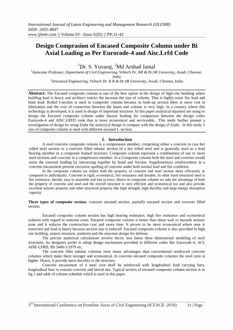
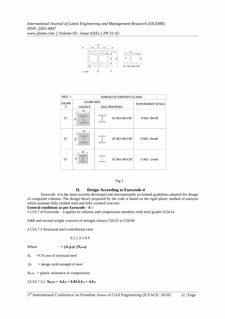
Concrete encasement of a steel core shall be reinforced with longitudinal load carrying bars,
longitudinal bars to restrain concrete and lateral ties. Typical section of encased composite column section is in
fig 1 and table of column schedule which is used in this paper.
International Journal of Latest Engineering and Management Research (IJLEMR)
ISSN: 2455-4847
www.ijlemr.com || Volume 03 - Issue 02(S) || PP.31-42
3rd
International Conference on Frontline Areas of Civil Engineering (ICFACE–2018) 32 | Page
Fig 1
II. Design According to Eurocode-4 Eurocode -4 is the most recently developed and internationally acclaimed guidelines adopted for design
of composite columns. The design theory proposed by the code is based on the rigid plastic method of analysis
which assumes fully yielded steel and fully crushed concrete.
General conditions as per Eurocode - 4 :-
1.Cl.6.7 of Eurocode – 4 applies to columns and compression members with steel grades S234 to
S460 and normal weight concrete of strength classes C20/25 to C50/60
2.Cl.6.7.1 Structural steel contribution ratio
0.2 ≤ δ ≤ 0.9
Where δ = (Aa.fyd)/ (Npl.Rd)
Aa =C/S area of structural steel
fyd = design yield strength of steel
Npl.Rd = plastic resistance to compression
3.Cl.6.7.3.2 Npl.Rd = Aafyd + 0.85Acfcd + Asfsd
International Journal of Latest Engineering and Management Research (IJLEMR)
ISSN: 2455-4847
www.ijlemr.com || Volume 03 - Issue 02(S) || PP.31-42
3rd
International Conference on Frontline Areas of Civil Engineering (ICFACE–2018) 33 | Page
Where,
Ac = area of concrete
fcd = design cylindrical strength of concrete As = Area
of reinforced steel
fsd = design yield strength of reinforced steel
Eurocode – 4 discusses two methods of design of composite column A .
General method of design:
The effect of local buckling of the steel section on the resistance shall be considered in design. The
effects of local buckling may be neglected for a steel section fully encased if the concrete cover to the flange of
a fully encased steel section should
a. Not be less than 40 mm.
b. Nor less than one-sixth of the breadth b of flange .
B . Simplified method
Scope of simplified method
1. Double symmetry cross sections. 2. Uniform cross-sections over the member length with rolled,
cold – formed or welded steel sections. 3. Steel contribution ratio
0.2 ≤ δ ≤ 0.9 :
[ if δ ≤ 0.2 - the column should be treated as reinforced concrete]
[ if δ ≥ 0.9 - the column should be treated as structural steel]
4. The non dimensional slenderness λ ≤ 2 5. Longitudinal reinforcement ratio
0.3% δ p δ 6% p = As / Ac
6. The ratio of depth to the width of the composite cross section
should be within the limit of
0.2 to 0.5.
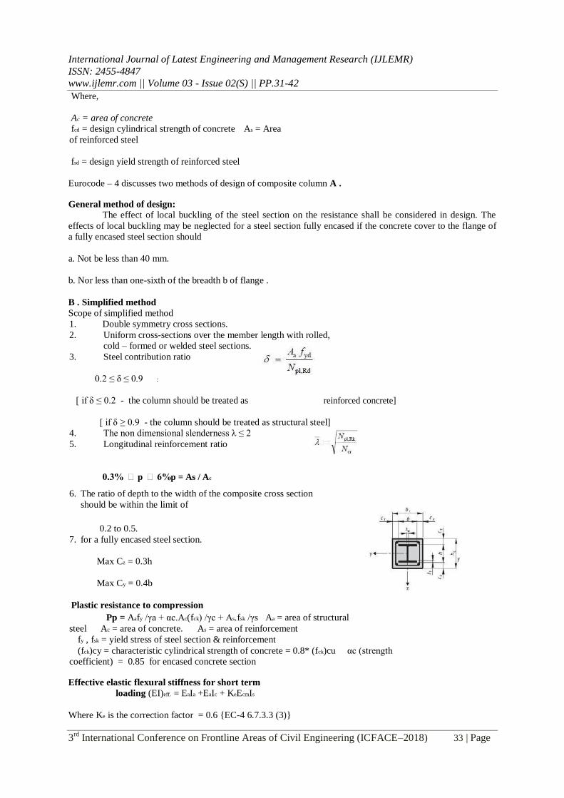
7. for a fully encased steel section.
Max Cz = 0.3h
Max Cy = 0.4b
Plastic resistance to compression
Pp = Aafy /γa + αc.Ac(fck) /γc + As.fsk /γs Aa = area of structural
steel Ac = area of concrete. As = area of reinforcement
fy , fsk = yield stress of steel section & reinforcement
(fck)cy = characteristic cylindrical strength of concrete = 0.8* (fck)cu αc (strength
coefficient) = 0.85 for encased concrete section
Effective elastic flexural stiffness for short term
loading (EI)eff. = EaIa +EaIc + KeEcmIs
Where Ke is the correction factor = 0.6 {EC-4 6.7.3.3 (3)}
International Journal of Latest Engineering and Management Research (IJLEMR)
ISSN: 2455-4847
www.ijlemr.com || Volume 03 - Issue 02(S) || PP.31-42
3rd
International Conference on Frontline Areas of Civil Engineering (ICFACE–2018) 34 | Page
Ia , Ic, Is are second moment of area of structural steel , uncracked concrete section & reinforcement.
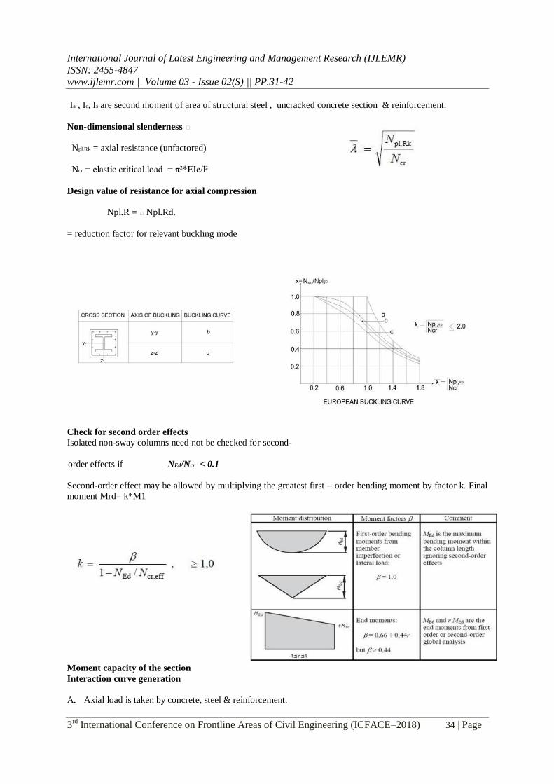
Non-dimensional slenderness δ
Npl,Rk = axial resistance (unfactored)
Ncr = elastic critical load = π²*EIe/l²
Design value of resistance for axial compression
Npl.R = χNpl.Rd.
= reduction factor for relevant buckling mode
Check for second order effects
Isolated non-sway columns need not be checked for second-
order effects if NEd/Ncr < 0.1
Second-order effect may be allowed by multiplying the greatest first – order bending moment by factor k. Final
moment Mrd= k*M1
Moment capacity of the section
Interaction curve generation
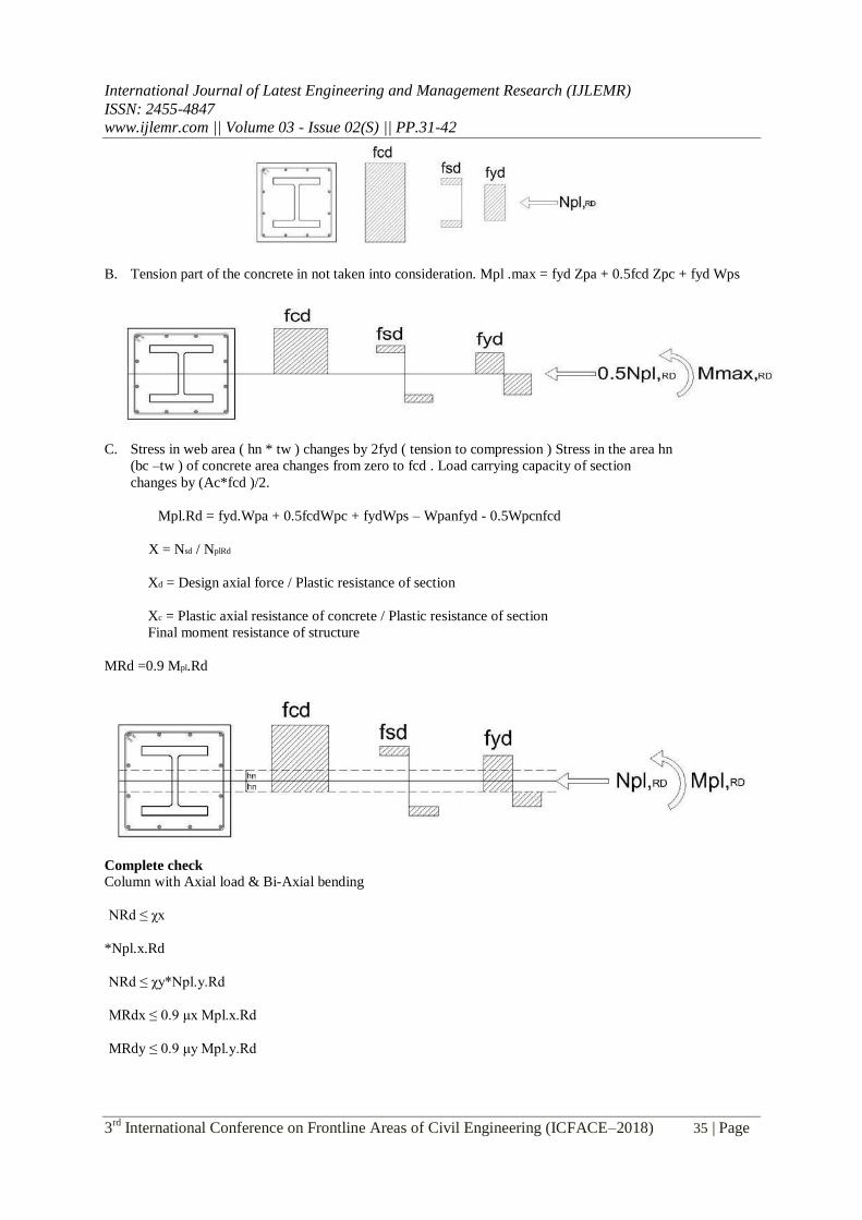
A. Axial load is taken by concrete, steel & reinforcement.
International Journal of Latest Engineering and Management Research (IJLEMR)
ISSN: 2455-4847
www.ijlemr.com || Volume 03 - Issue 02(S) || PP.31-42
3rd
International Conference on Frontline Areas of Civil Engineering (ICFACE–2018) 35 | Page
B. Tension part of the concrete in not taken into consideration. Mpl .max = fyd Zpa + 0.5fcd Zpc + fyd Wps
C. Stress in web area ( hn * tw ) changes by 2fyd ( tension to compression ) Stress in the area hn
(bc –tw ) of concrete area changes from zero to fcd . Load carrying capacity of section
changes by (Ac*fcd )/2.
Mpl.Rd = fyd.Wpa + 0.5fcdWpc + fydWps – Wpanfyd - 0.5Wpcnfcd
X = Nsd / NplRd
Xd = Design axial force / Plastic resistance of section
Xc = Plastic axial resistance of concrete / Plastic resistance of section
Final moment resistance of structure
MRd =0.9 Mpl.Rd
Complete check
Column with Axial load & Bi-Axial bending
NRd ≤ χx
*Npl.x.Rd
NRd ≤ χy*Npl.y.Rd
MRdx ≤ 0.9 μx Mpl.x.Rd
MRdy ≤ 0.9 μy Mpl.y.Rd
International Journal of Latest Engineering and Management Research (IJLEMR)
ISSN: 2455-4847
www.ijlemr.com || Volume 03 - Issue 02(S) || PP.31-42
3rd
International Conference on Frontline Areas of Civil Engineering (ICFACE–2018) 36 | Page
Interaction check
Mx Muy ≤ 1
µxM pl.x.Rd µyM pl.y.Rd
III. Design According To Aisc AISC-LRFD: code proposes design mechanism for composite structures. According to the LRFD design
mechanism it believes that composite materials in a composite structure should act together to resist bending or
in other words as one i.e. monolithically.
Limitations
For encased composite members, the following limitations shall be met:
1) The cross sectional area of steel core should be comprises of at least 1% of the total composite cross section.
2) Concrete encasement of the steel core shall be reinforced with continuous longitudinal bars and lateral
pies or spirals. .
Maximum spacing of lateral ties should not be greater than 0.5 times the least column dimension.
3) The minimum reinforcement ratio for continuous longitudinal reinforcing, ρsr, shall be
0.004, where ρsr is given by : ρsr =
Asr/Ag where
Ag = gross area of composite member in (mm²)
Asr = area of continuos reinforcing bars in (mm²)
Nominal Compressive Strength The resistance and safety factors used in calculation of design and allowable design compressive strength , φc Pn are:
φc = 0.75 (LFRD)
The slenderness ratio is preferably should not exceed 200 (AISC E2).
The nominal compressive strength of members of doubly symmetric axially loaded encased composite sections,
Pn, is the value obtained in accordance with the limit state of flexural buckling. The torsional and flexural-
torsional buckling limit states do not need to be considered.
When Pno/Pe ≤ 2.25
Pn = Pno 0.658 Pno/Pe
When Pno/Pe > 2.25
Pn = 0.877 Pe
Pno = FyAs + FysrAsr + 0.85fc’Ac
Pe = elastical critical buckling load
= π2(EIeff.)/(KL)
2
Ac = area of concrete in m2
International Journal of Latest Engineering and Management Research (IJLEMR)
ISSN: 2455-4847
www.ijlemr.com || Volume 03 - Issue 02(S) || PP.31-42
3rd
International Conference on Frontline Areas of Civil Engineering (ICFACE–2018) 37 | Page
As = area of the steel section, in m2
Ec = modulus of elasticity of concrete as input by the user , ksi
Eleff. = effective stiffness of the composite section, kip-in2
= EsIs + 0.5EsIsr + C1EcIc
C1= coefficient for calculation of effective rigidity of an encased composite compression member
= 0.1 + 2* As /(As +Ac)
Es = modulus of elasticity of steel
= 29,000 ksi
Fy = specified minimum yield stress of steel section, ksi
Fysr = specified minimum yield stress of reinforcing bars, ksi
Ic = most of inertia of the concrete section about the elastic neutral axis of the composite section, in4
Is = moment of inertia of steel shape about the elastic neutral axis of the composite section, in4 Isr = moment of
inertia of reinforcing bars about the elastic neutral axis of the composite section, in4
K = effective length factor = K2
L = laterally unbraced length of the member, in.
f’c = specified compressive strength of
concrete, ksi Nominal flexural strength
This section applies to members subjected to simple bending about one principal axis. The members are
assumed to be loaded in a plane parallel to a principal axis that passes through the shear centre, or restrained
against twisting.
The design flexural strength, φbMn is determined using the resistance and safety factors:
φb = 0.90 (LFRD)
Encased I-Rectangular sections
The plastic moment capacity in the major
direction,
Mp,major = MD – ZsnFy-1/2Zcn(0.85fc’)
Zcn = h1hn2 – Zs- Zsn
Where,
MD = ZsFy + ZrFyr + 1/2Zc(0.85fc’)
Zs = full x axis plastic section modulus of a stell I-shape
Zr = full x axis plastic modulus of reinforcement
International Journal of Latest Engineering and Management Research (IJLEMR)
ISSN: 2455-4847
www.ijlemr.com || Volume 03 - Issue 02(S) || PP.31-42
3rd
International Conference on Frontline Areas of Civil Engineering (ICFACE–2018) 38 | Page
Asr = area of continuous longitudinal reinforcing bars
Zr = (As – Asrs)(h2/2-c)
Zc = h1h22 /4-Zs-Zr
The position of hn and Zsn depends on the position of plastic neutral axis.
The plastic moment capacity in minor direction, Mp , is calculated as follows :
Mp,minor = MD - ZsnFy – 1/2Zcn(0.85f’c)
Zcn = h1h2n - Zsn
Where,
MD = ZSFy + ZrFsr + 1/2Zc(0.85f’c)
Zr = section modulus of reinforcement
Asr = area of continuous longitudinal reinforcing bars
Zr =Asr(h2/2-c)
Zc = h1h22/4 – Zc – Zr
The position of hn and Zsn depends on the position of plastic neutral axis.
Design of members for combined forces
Members subjected to flexure and axial compression
For Pr/Pc ≥ 0.2
Pr/Pc+8/9(Mr33/Mc33+Mr22/Mc22)≤1.0 For
Pr/Pc <0.2
Pr/2Pc + (Mr33/Mc33 + Mr22/Mc22)≤ 1.0
Where Pr and Pc are the required and available axial strengths; Mr and Mc are the required and
available flexural strengths; and 3 and 2 represent the strong and weak axes, respectively.
For design in accordance with LFRD provisions:
Pt = required axial compressive strength using LFRD load combinations
Pc = design axial compressive strength = φcPn
Mr = required flexural strength using LFRD combinations
Mc = design flexural strength = φbMn φc = resistance
factor for compression =0.75 φb = resistance factor
for flexure =0.90
International Journal of Latest Engineering and Management Research (IJLEMR)
ISSN: 2455-4847
www.ijlemr.com || Volume 03 - Issue 02(S) || PP.31-42
3rd
International Conference on Frontline Areas of Civil Engineering (ICFACE–2018) 39 | Page
IV. Interactive Composite Column Design The interactive composite column design command is an easy mode that allows to review the design
results for any composite column design and interactively revise the design assumptions and immediately
review the revised results. Etabs is analysis and design software that access the user to select design code as
long as structure have first been model and analyze data such as material property and member forces are
directly recovered from the model data base and are user defined or default design settings. As with the design
applications the user should carefully review all of the user option and default setting before the design process
that it is correct and according to code. The software is a better option to make user the direct analysis because it
can capture the second order P-delta analysis and P- delta effect.
Stress check
Composite column design/check consists of calculating flexural, axial and shear forces or stress at
several locations along the length of the member and then comparing those calculated values with acceptable
limits. That comparison produces the demand/capacity ratio, which typically should not exceed a value of one if
code requirement are to be satisfied. The programs follows the same review procedures whether it is checking a
user specified shape or a shape selected by the program from a predefined list. The program also check the
requirements for the beam column capacity ratio, checks the capacity of the panel zone, and calculates the
doubler plate and continuity plate thickness, if needed. The program does not do the connection design.
However, it calculates the design the basis forces for connection design.
Material properties
a)Structural steel
Characteristic Yield strength fy = 350 N/mm2
Modulus of elasticity Ea =200000.00 N/mm2
b) Reinforcing Steel
Characteristic Yield Strength fsk =500.00 N/mm2
Modulus of elasticity Es =200000.00 N/mm2
c) Concrete
Characteristic Comp. Strength (Cube) (fck)cu = 50.00 N/mm2
Characteristics Comp. Strength (Cylinder) (fck)cy =40.00 N/mm2
Secant modulus of Elasticity for short term loading,
Ecm = 5700(sqrt(fck)cu)
Ecm = 40305.09 N/mm2
=5700*SQRT(40)
d) Partial Safety Factors
Structural steel Ya = 1.10
Reinforcing steel Ys =1.15
Concrete Yc = 1.50
Load input
Design axial force (Factored) Ned = 28691.00 KN Max. Moment about
Major axis (factored) Mx = 101.80 KN-m
Max. Moment about Minor axis (factored) My =251.00 KN-m
Effective length of column Le = 4.68m
Section
Section C1 , C2 and C3 is defined and assign as per the model , model is single line element of length 4.68m , and
assign loads for the analysis and design of the composite column , and the strength calculation of the member .
International Journal of Latest Engineering and Management Research (IJLEMR)
ISSN: 2455-4847
www.ijlemr.com || Volume 03 - Issue 02(S) || PP.31-42
3rd
International Conference on Frontline Areas of Civil Engineering (ICFACE–2018) 40 | Page
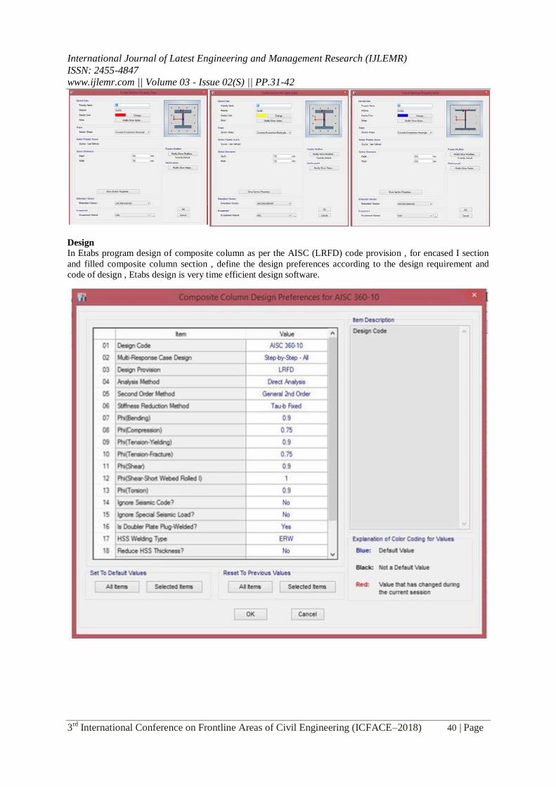
Design
In Etabs program design of composite column as per the AISC (LRFD) code provision , for encased I section
and filled composite column section , define the design preferences according to the design requirement and
code of design , Etabs design is very time efficient design software.
International Journal of Latest Engineering and Management Research (IJLEMR)
ISSN: 2455-4847
www.ijlemr.com || Volume 03 - Issue 02(S) || PP.31-42
3rd
International Conference on Frontline Areas of Civil Engineering (ICFACE–2018) 41 | Page
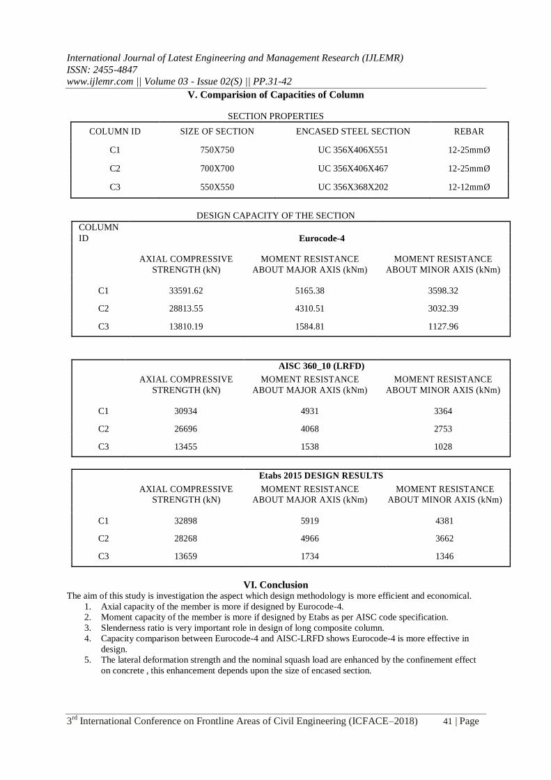
V. Comparision of Capacities of Column
SECTION PROPERTIES
COLUMN ID SIZE OF SECTION ENCASED STEEL SECTION REBAR
C1 750X750 UC 356X406X551 12-25mmØ
C2 700X700 UC 356X406X467 12-25mmØ
C3 550X550 UC 356X368X202 12-12mmØ
DESIGN CAPACITY OF THE SECTION
COLUMN
ID Eurocode-4
AXIAL COMPRESSIVE MOMENT RESISTANCE MOMENT RESISTANCE
STRENGTH (kN) ABOUT MAJOR AXIS (kNm) ABOUT MINOR AXIS (kNm)
C1 33591.62 5165.38 3598.32
C2 28813.55 4310.51 3032.39
C3 13810.19 1584.81 1127.96
AISC 360_10 (LRFD)
AXIAL COMPRESSIVE MOMENT RESISTANCE MOMENT RESISTANCE
STRENGTH (kN) ABOUT MAJOR AXIS (kNm) ABOUT MINOR AXIS (kNm)
C1 30934 4931 3364
C2 26696 4068 2753
C3 13455 1538 1028
Etabs 2015 DESIGN RESULTS
AXIAL COMPRESSIVE MOMENT RESISTANCE MOMENT RESISTANCE
STRENGTH (kN) ABOUT MAJOR AXIS (kNm) ABOUT MINOR AXIS (kNm)
C1 32898 5919 4381
C2 28268 4966 3662
C3 13659 1734 1346
VI. Conclusion The aim of this study is investigation the aspect which design methodology is more efficient and economical.
1. Axial capacity of the member is more if designed by Eurocode-4. 2. Moment capacity of the member is more if designed by Etabs as per AISC code specification. 3. Slenderness ratio is very important role in design of long composite column. 4. Capacity comparison between Eurocode-4 and AISC-LRFD shows Eurocode-4 is more effective in
design. 5. The lateral deformation strength and the nominal squash load are enhanced by the confinement effect
on concrete , this enhancement depends upon the size of encased section.
International Journal of Latest Engineering and Management Research (IJLEMR)
ISSN: 2455-4847
www.ijlemr.com || Volume 03 - Issue 02(S) || PP.31-42
3rd
International Conference on Frontline Areas of Civil Engineering (ICFACE–2018) 42 | Page
References [1] Sharad .S. Adlinge , A.k.Gupta . study of ultimate load capacity encased steel columns using finite
element method , International Journal of advance research , IJOAR .org.
[2] Composite structure of steel & concrete by R.P JOHNSON , second edition , volumn-1, Blackwell
scientific publication .
[3] Composite Column Design Manual AISC 360-10 for ETABS 2016.
[4] Simplified Design of Composite Columns , Based on a Comparative Study of the Development of
Building Regulations in Germany and the United States . Holger Eggemann
[5] Eurocode-4 : Design of composite steel and concrete structures .
[6] ANSI/AISC 360-10 : Specification for Structural Steel Buildings .