Embed Size (px)
Citation preview
Innovation Made to Order PlastiComp, Inc.
110 Galewski Drive • Winona, Minnesota, U.S.A. Internet: www.plasticomp.com • Email: [email protected]
Telephone: +1 507.858.0330
Design Considerations for Successfully Using
Long Fiber Reinforced Thermoplastic Composites
White Paper
© Copyright PlastiComp, Inc. Page 1 of 8
DESIGN CONSIDERATIONS FOR SUCCESSFULLY USING
LONG FIBER REINFORCED THERMOPLASTIC COMPOSITES
PlastiComp, Inc., 110 Galewski Dr., Winona, Minnesota, U.S.A. Telephone +1 (507) 858-0330, Internet www.plasticomp.com
Abstract ‒ Long fiber thermoplastic (LFT) composite design studies often emphasize fiber content but are sketchy on fiber-orientation, fiber-matrix interface, and mold design. At PlastiComp we use an all-inclusive approach to successfully deploy LFT materials in metal replacement applications. Examples show how long carbon-fiber compounds were successfully substituted for die-cast magnesium by redesigning the application for injection molding production. Achieving tailored fiber architectures at key stress locations through strategic gate locations, as advised through Finite Element Analysis (FEA) and Mold Flow Analysis (MFA). Maximizing mechanical properties through optimized molding processes. INTRODUCTION Fiber reinforcement of thermoplastic or thermoset resins is a mature science [1]. The earliest applications were in the aerospace sector, such as nose cones in missiles, where phenolic-based matrices were reinforced with carbon fibers. Currently, the use of thermoplastics in various industrial sectors is increasing because they do away with potentially toxic manufacturing processes and afford faster and simplified production methods that lower cost and speed time to market. They are also largely recyclable. As opposed to thermoset composites, the fiber-reinforcement in thermoplastics is mostly discontinuous since it has to lend itself to common manufacturing processes such as injection molding. Although several alternate manufacturing processes can accommodate continuous reinforcements, we concentrate on injection-molded long fiber reinforced thermoplastic composites. Since the emphasis is on discontinuous reinforcement, it is important to consider the length and orientation of fibers in these
composites. Most fiber-reinforced thermoplastics contain short chopped or milled fibers which do not possess the necessary fiber length or aspect ratio to act as effective reinforcement. Long-fiber reinforcement fills this gap, with aspect ratios routinely over 800. Additionally, fiber-morphology, fiber-diameter and fiber-matrix adhesion impact composite properties. At best, there is scattered information about these issues and their role in designing with long-fiber composites and examples, to illustrate how best practices are implemented. Usually, fiber content is increased in regular steps and the resulting properties are reported without further commentary. In this paper, we supplement that traditional approach with a careful consideration of all design factors that can expand the design space available to engineers, allowing them to meet product specifications. LONG FIBER THERMOPLASTICS Figure 1 is a schematic illustration of the production of LFT pellets or granules at PlastiComp.
© Copyright PlastiComp, Inc. Page 2 of 8
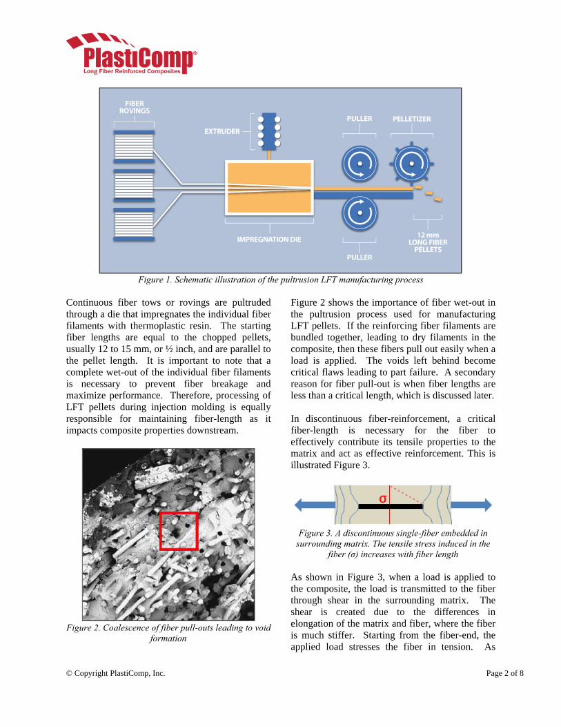
Figure 1. Schematic illustration of the pultrusion LFT manufacturing process
Continuous fiber tows or rovings are pultruded through a die that impregnates the individual fiber filaments with thermoplastic resin. The starting fiber lengths are equal to the chopped pellets, usually 12 to 15 mm, or ½ inch, and are parallel to the pellet length. It is important to note that a complete wet-out of the individual fiber filaments is necessary to prevent fiber breakage and maximize performance. Therefore, processing of LFT pellets during injection molding is equally responsible for maintaining fiber-length as it impacts composite properties downstream.
Figure 2. Coalescence of fiber pull-outs leading to void
formation
Figure 2 shows the importance of fiber wet-out in the pultrusion process used for manufacturing LFT pellets. If the reinforcing fiber filaments are bundled together, leading to dry filaments in the composite, then these fibers pull out easily when a load is applied. The voids left behind become critical flaws leading to part failure. A secondary reason for fiber pull-out is when fiber lengths are less than a critical length, which is discussed later. In discontinuous fiber-reinforcement, a critical fiber-length is necessary for the fiber to effectively contribute its tensile properties to the matrix and act as effective reinforcement. This is illustrated Figure 3.
Figure 3. A discontinuous single-fiber embedded in
surrounding matrix. The tensile stress induced in the fiber (σ) increases with fiber length
As shown in Figure 3, when a load is applied to the composite, the load is transmitted to the fiber through shear in the surrounding matrix. The shear is created due to the differences in elongation of the matrix and fiber, where the fiber is much stiffer. Starting from the fiber-end, the applied load stresses the fiber in tension. As
© Copyright PlastiComp, Inc. Page 3 of 8
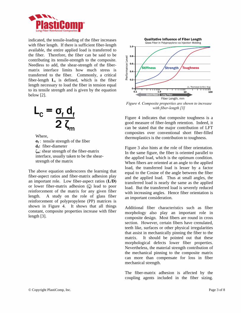
indicated, the tensile-loading of the fiber increases with fiber length. If there is sufficient fiber-length available, the entire applied load is transferred to the fiber. Therefore, the fiber can be said to be contributing its tensile-strength to the composite. Needless to add, the shear-strength of the fiber-matrix interface limits how much stress is transferred to the fiber. Commonly, a critical fiber-length Lc is defined, which is the fiber length necessary to load the fiber in tension equal to its tensile strength and is given by the equation below [2].
Where, σf : tensile strength of the fiber df: fiber-diameter ζm: shear strength of the fiber-matrix interface, usually taken to be the shear-strength of the matrix
The above equation underscores the learning that fiber-aspect ratios and fiber-matrix adhesion play an important role. Low fiber-aspect ratios (L/D) or lower fiber-matrix adhesion (ζ) lead to poor reinforcement of the matrix for any given fiber length. A study on the role of glass fiber reinforcement of polypropylene (PP) matrices is shown in Figure 4. It shows that all things constant, composite properties increase with fiber length [3].
Figure 4. Composite properties are shown to increase
with fiber-length [3] Figure 4 indicates that composite toughness is a good measure of fiber-length retention. Indeed, it can be stated that the major contribution of LFT composites over conventional short fiber-filled thermoplastics is the contribution to toughness. Figure 3 also hints at the role of fiber orientation. In the same figure, the fiber is oriented parallel to the applied load, which is the optimum condition. When fibers are oriented at an angle to the applied load, the transferred load is lesser by a factor equal to the Cosine of the angle between the fiber and the applied load. Thus at small angles, the transferred load is nearly the same as the applied load. But the transferred load is severely reduced with increasing angles. Hence fiber orientation is an important consideration. Additional fiber characteristics such as fiber morphology also play an important role in composite design. Most fibers are round in cross section. However, certain fibers have crenulated, teeth like, surfaces or other physical irregularities that assist in mechanically pinning the fiber to the matrix. It should be pointed out that these morphological defects lower fiber properties. Nevertheless, the material strength contribution of the mechanical pinning to the composite matrix can more than compensate for loss in fiber mechanical strength.
The fiber-matrix adhesion is affected by the coupling agents included in the fiber sizing.
© Copyright PlastiComp, Inc. Page 4 of 8
While the details are not elaborated on here, it is common to hear about “nylon glass” or “polypropylene glass” which is a personalization of specific sizing compositions used for specific thermoplastic matrixes. Fiber-sizing development is advanced in the thermoset matrix industry, because of the predominance of fiber-reinforced epoxy, polyester and vinyl ester -based composites usage in industrial sectors such as aerospace and wind energy. There is a need for rapid development of fiber sizings for thermoplastics matrixes. Furthermore, this development is best undertaken by fiber manufacturers since implementing post-manufacturing changes to fiber surfaces invariably leads to fiber degradation. Injection molding is the chief manufacturing process for LFT materials and the plasticizing screw plays an important role. Since the principle mechanism of fiber-degradation is shear in the melt phase, or at the mold walls and fiber-fiber interactions, the melt viscosity affects fiber lengths. It is accounted for, in processing conditions such as injection speed and pressure. Large compression ratios (3:1) and high injection speeds ( >50 rpm ) and back pressure ( >50 psi ) lead to fiber-length degradation. Secondly, the runners and gates used in injection molding severely affect fiber-length. It has been determined that 55.2% of fiber-length attrition occurs at the injection nozzle, another 31.3% in the injection gate and 13.5% fiber attrition in the mold center [4]. The recommended sizes for nozzles and gates must be strictly followed. In summary, composite strength is a function of several factors as illustrated in Figure 5, altering any one can result in a performance increase or decrease.
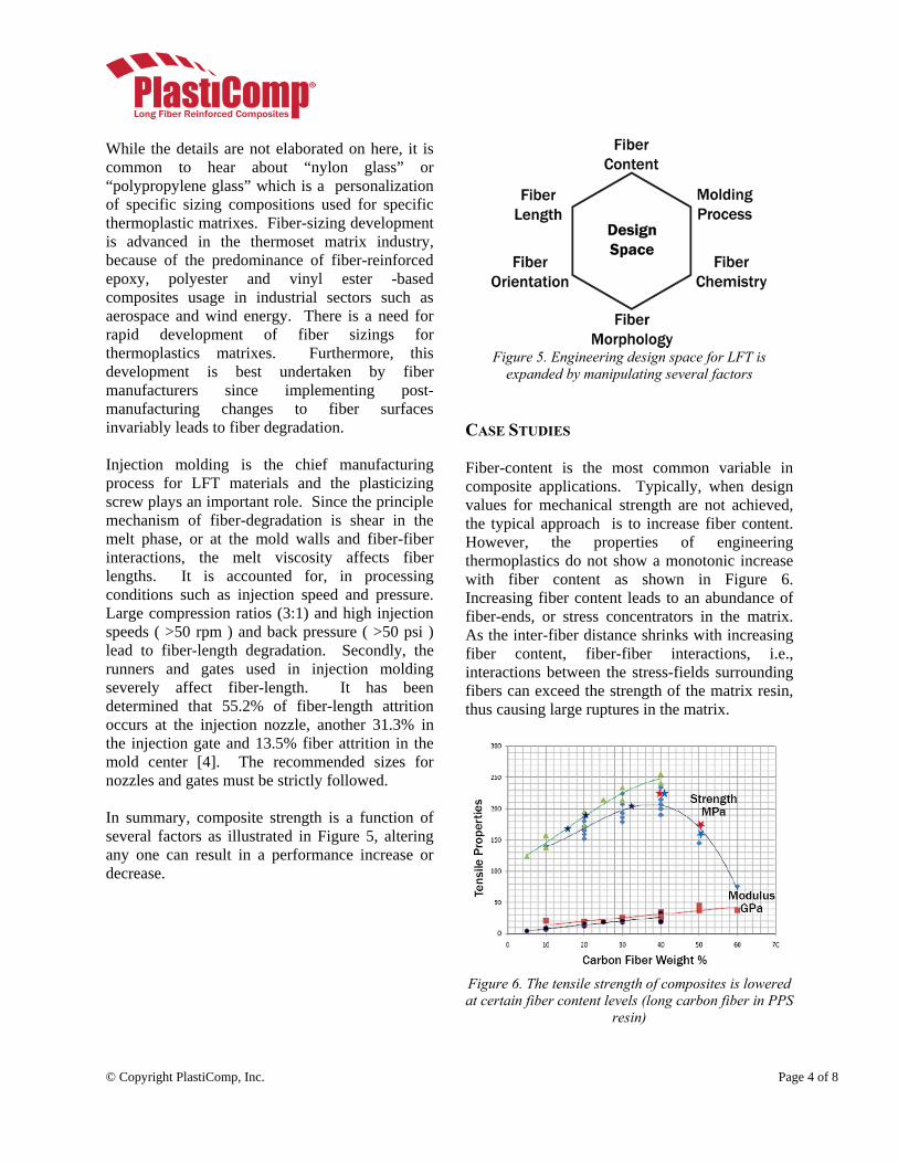
Figure 5. Engineering design space for LFT is
expanded by manipulating several factors CASE STUDIES Fiber-content is the most common variable in composite applications. Typically, when design values for mechanical strength are not achieved, the typical approach is to increase fiber content. However, the properties of engineering thermoplastics do not show a monotonic increase with fiber content as shown in Figure 6. Increasing fiber content leads to an abundance of fiber-ends, or stress concentrators in the matrix. As the inter-fiber distance shrinks with increasing fiber content, fiber-fiber interactions, i.e., interactions between the stress-fields surrounding fibers can exceed the strength of the matrix resin, thus causing large ruptures in the matrix.
Figure 6. The tensile strength of composites is lowered at certain fiber content levels (long carbon fiber in PPS
resin)
© Copyright PlastiComp, Inc. Page 5 of 8
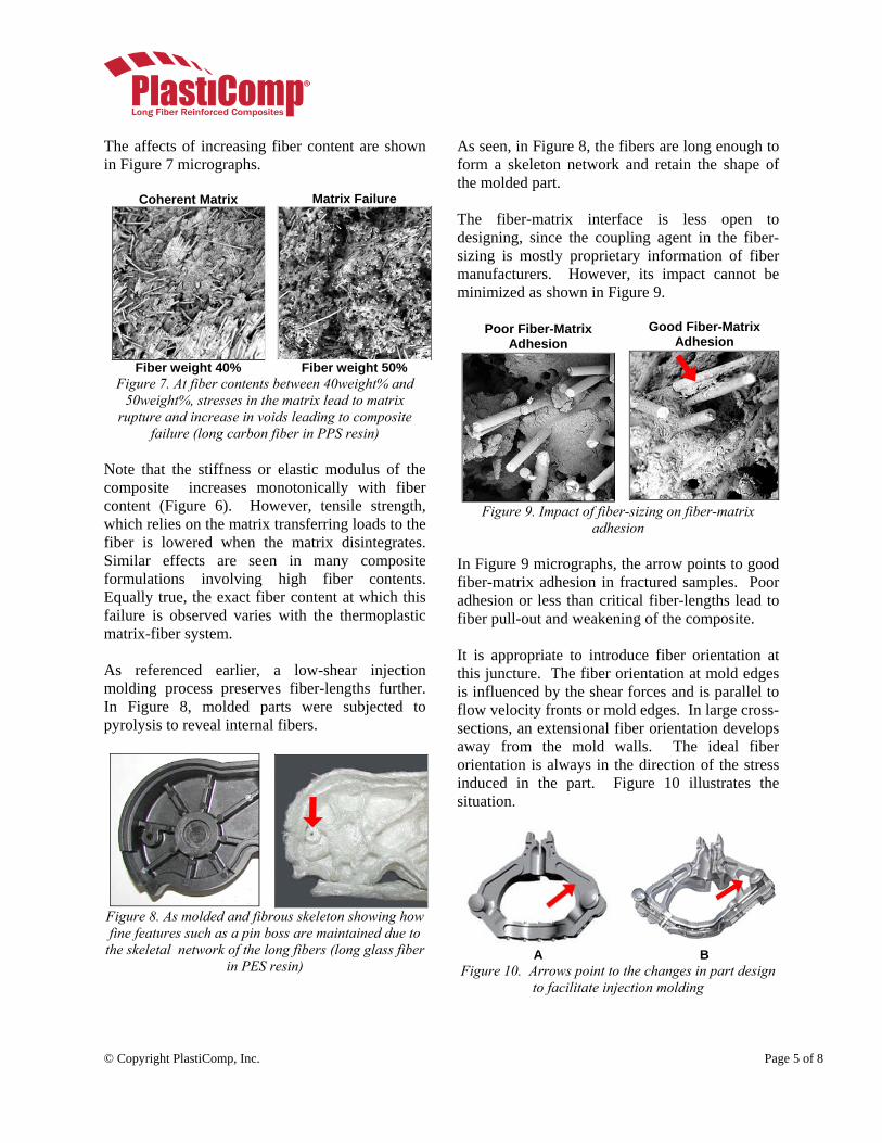
The affects of increasing fiber content are shown in Figure 7 micrographs.
Coherent Matrix
Fiber weight 40%
Matrix Failure
Fiber weight 50% Figure 7. At fiber contents between 40weight% and
50weight%, stresses in the matrix lead to matrix rupture and increase in voids leading to composite
failure (long carbon fiber in PPS resin) Note that the stiffness or elastic modulus of the composite increases monotonically with fiber content (Figure 6). However, tensile strength, which relies on the matrix transferring loads to the fiber is lowered when the matrix disintegrates. Similar effects are seen in many composite formulations involving high fiber contents. Equally true, the exact fiber content at which this failure is observed varies with the thermoplastic matrix-fiber system. As referenced earlier, a low-shear injection molding process preserves fiber-lengths further. In Figure 8, molded parts were subjected to pyrolysis to reveal internal fibers.
Figure 8. As molded and fibrous skeleton showing how fine features such as a pin boss are maintained due to
the skeletal network of the long fibers (long glass fiber in PES resin)
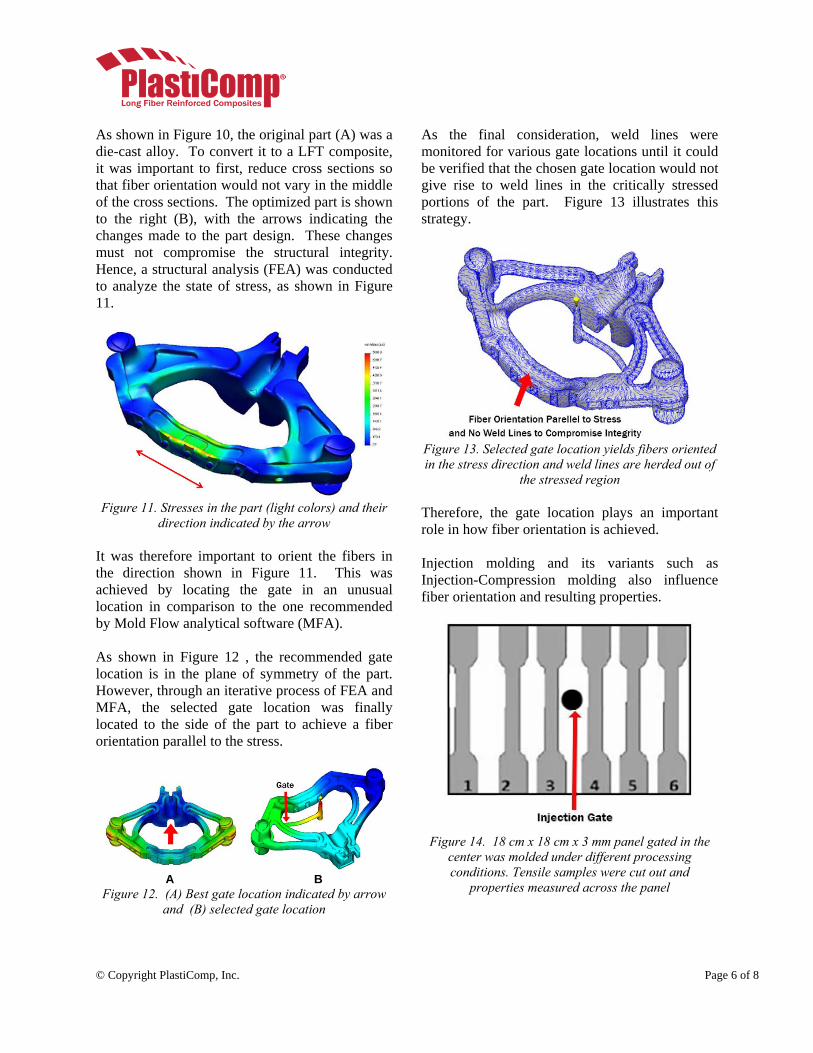
As seen, in Figure 8, the fibers are long enough to form a skeleton network and retain the shape of the molded part. The fiber-matrix interface is less open to designing, since the coupling agent in the fiber-sizing is mostly proprietary information of fiber manufacturers. However, its impact cannot be minimized as shown in Figure 9.
Poor Fiber-Matrix Adhesion
Good Fiber-Matrix Adhesion
Figure 9. Impact of fiber-sizing on fiber-matrix adhesion
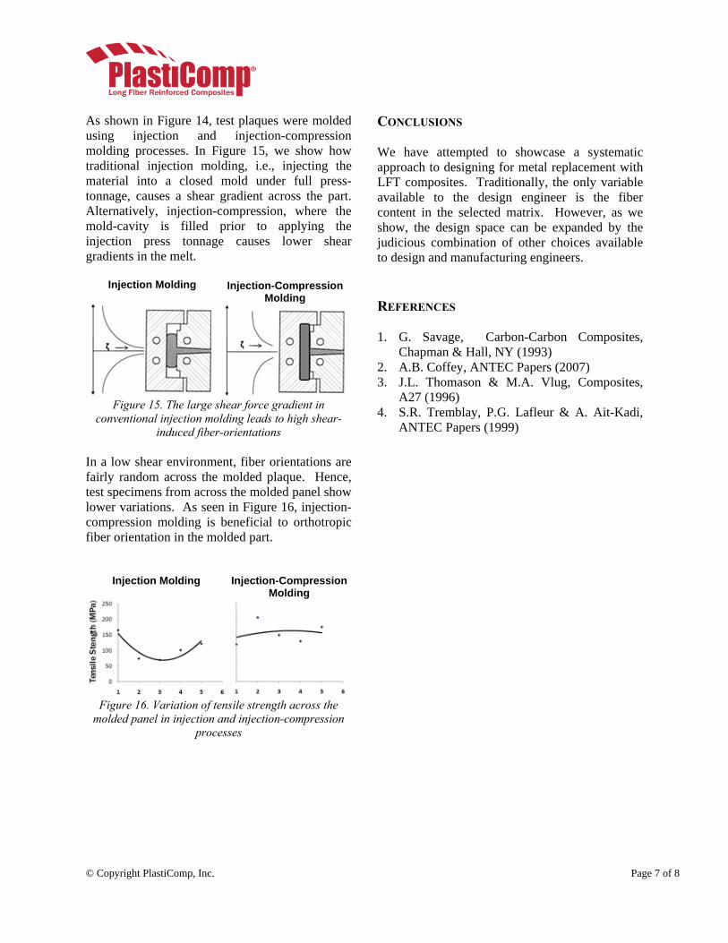
In Figure 9 micrographs, the arrow points to good fiber-matrix adhesion in fractured samples. Poor adhesion or less than critical fiber-lengths lead to fiber pull-out and weakening of the composite. It is appropriate to introduce fiber orientation at this juncture. The fiber orientation at mold edges is influenced by the shear forces and is parallel to flow velocity fronts or mold edges. In large cross-sections, an extensional fiber orientation develops away from the mold walls. The ideal fiber orientation is always in the direction of the stress induced in the part. Figure 10 illustrates the situation.
A
B
Figure 10. Arrows point to the changes in part design to facilitate injection molding
© Copyright PlastiComp, Inc. Page 6 of 8
As shown in Figure 10, the original part (A) was a die-cast alloy. To convert it to a LFT composite, it was important to first, reduce cross sections so that fiber orientation would not vary in the middle of the cross sections. The optimized part is shown to the right (B), with the arrows indicating the changes made to the part design. These changes must not compromise the structural integrity. Hence, a structural analysis (FEA) was conducted to analyze the state of stress, as shown in Figure 11.
Figure 11. Stresses in the part (light colors) and their
direction indicated by the arrow
It was therefore important to orient the fibers in the direction shown in Figure 11. This was achieved by locating the gate in an unusual location in comparison to the one recommended by Mold Flow analytical software (MFA). As shown in Figure 12 , the recommended gate location is in the plane of symmetry of the part. However, through an iterative process of FEA and MFA, the selected gate location was finally located to the side of the part to achieve a fiber orientation parallel to the stress.
A B
Figure 12. (A) Best gate location indicated by arrow and (B) selected gate location
As the final consideration, weld lines were monitored for various gate locations until it could be verified that the chosen gate location would not give rise to weld lines in the critically stressed portions of the part. Figure 13 illustrates this strategy.
Figure 13. Selected gate location yields fibers oriented in the stress direction and weld lines are herded out of
the stressed region
Therefore, the gate location plays an important role in how fiber orientation is achieved.
Injection molding and its variants such as Injection-Compression molding also influence fiber orientation and resulting properties.
Figure 14. 18 cm x 18 cm x 3 mm panel gated in the
center was molded under different processing conditions. Tensile samples were cut out and
properties measured across the panel
© Copyright PlastiComp, Inc. Page 7 of 8
As shown in Figure 14, test plaques were molded using injection and injection-compression molding processes. In Figure 15, we show how traditional injection molding, i.e., injecting the material into a closed mold under full press-tonnage, causes a shear gradient across the part. Alternatively, injection-compression, where the mold-cavity is filled prior to applying the injection press tonnage causes lower shear gradients in the melt.
Injection Molding
Injection-Compression Molding
Figure 15. The large shear force gradient in conventional injection molding leads to high shear-
induced fiber-orientations In a low shear environment, fiber orientations are fairly random across the molded plaque. Hence, test specimens from across the molded panel show lower variations. As seen in Figure 16, injection-compression molding is beneficial to orthotropic fiber orientation in the molded part.
Injection Molding
Injection-Compression Molding
Figure 16. Variation of tensile strength across the molded panel in injection and injection-compression
processes
CONCLUSIONS We have attempted to showcase a systematic approach to designing for metal replacement with LFT composites. Traditionally, the only variable available to the design engineer is the fiber content in the selected matrix. However, as we show, the design space can be expanded by the judicious combination of other choices available to design and manufacturing engineers. REFERENCES 1. G. Savage, Carbon-Carbon Composites,
Chapman & Hall, NY (1993) 2. A.B. Coffey, ANTEC Papers (2007) 3. J.L. Thomason & M.A. Vlug, Composites,
A27 (1996) 4. S.R. Tremblay, P.G. Lafleur & A. Ait-Kadi,
ANTEC Papers (1999)

© Copyright PlastiComp, Inc. Page 8 of 8
Vertical provider of composite solutions focused on applying long fiber technology to new applications and markets
Stronger, tougher, and lighter composites engineered to meet your design and performance requirements
Long glass, carbon or specialty fiber reinforcement in thermoplastic polymers from PP to PEEK
Need to replace an under-performing material, need to find a lower-cost solution, or just starting to develop a new concept that requires high performance? Then stronger, tougher, and lighter long fiber reinforced thermoplastic composites are the material solution you want.
Complēt® long fiber reinforced composite pellets from PlastiComp encompass a complete portfolio of structural thermoplastic solutions tailored to meet your design and performance requirements.
Whether it’s long glass, carbon, or another specialty fiber combined with thermoplastic polymers ranging from polypropylene to PEEK, Complēt long fiber reinforced composite pellets are the ready-to-mold solution of choice for plastics processors and OEMs.
We put our composite expertise at your disposal, working with you from concept through component production, including performing CAE design and analysis to ensure your application obtains the maximum benefit from long fiber reinforcement.
Using our fully integrated approach to application development, PlastiComp views you as a long-term partner whose business we help grow and prosper – together.
Our application development team is available for no obligation product design and composite performance consultations. PlastiComp also provides complimentary
composite pellet evaluation samples to assure our solution is the right choice.
Eric Wollan VP Technology [email protected] (507) 858-0320
Steve Ouendag Business Development [email protected] (616) 250-1285
Visit www.plasticomp.com/complet/ to learn more about long fiber reinforced thermoplastic composites.