Embed Size (px)
Citation preview

DESIGN FOR MANUFACTURABILITY
March 2016
Jeremy Govier
Principal Engineer
PROPRIETARY - Property of Edmund Optics, Inc. | 2016 Copyright© Edmund Optics, Inc.
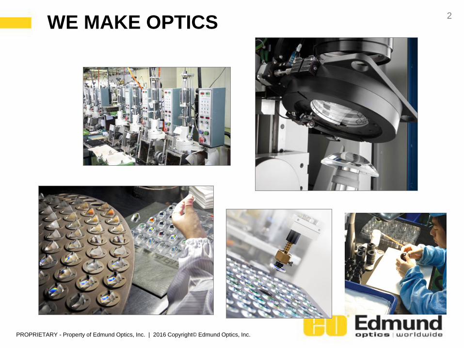
WE MAKE OPTICS2
PROPRIETARY - Property of Edmund Optics, Inc. | 2016 Copyright© Edmund Optics, Inc.
HOW TO REDUCE COST IN YOUR OPTICS3
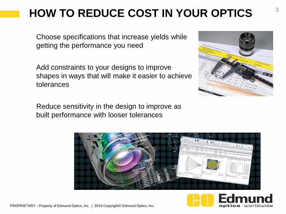
Choose specifications that increase yields while
getting the performance you need
Add constraints to your designs to improve
shapes in ways that will make it easier to achieve
tolerances
Reduce sensitivity in the design to improve as
built performance with looser tolerances
PROPRIETARY - Property of Edmund Optics, Inc. | 2016 Copyright© Edmund Optics, Inc.
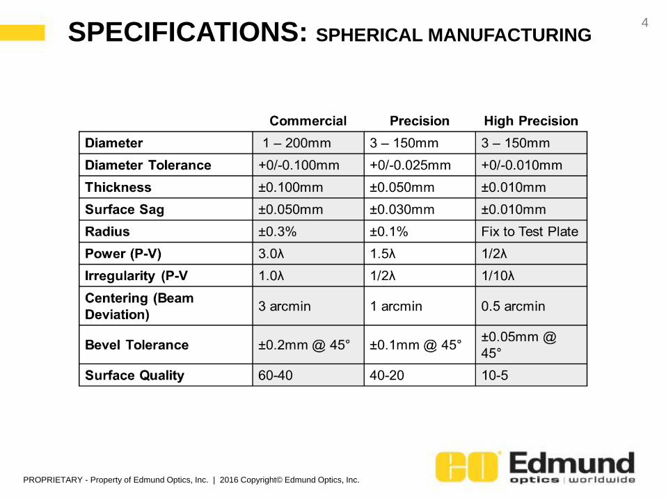
SPECIFICATIONS: SPHERICAL MANUFACTURING4
PROPRIETARY - Property of Edmund Optics, Inc. | 2016 Copyright© Edmund Optics, Inc.
YOU CANNOT HAVE IT ALL5
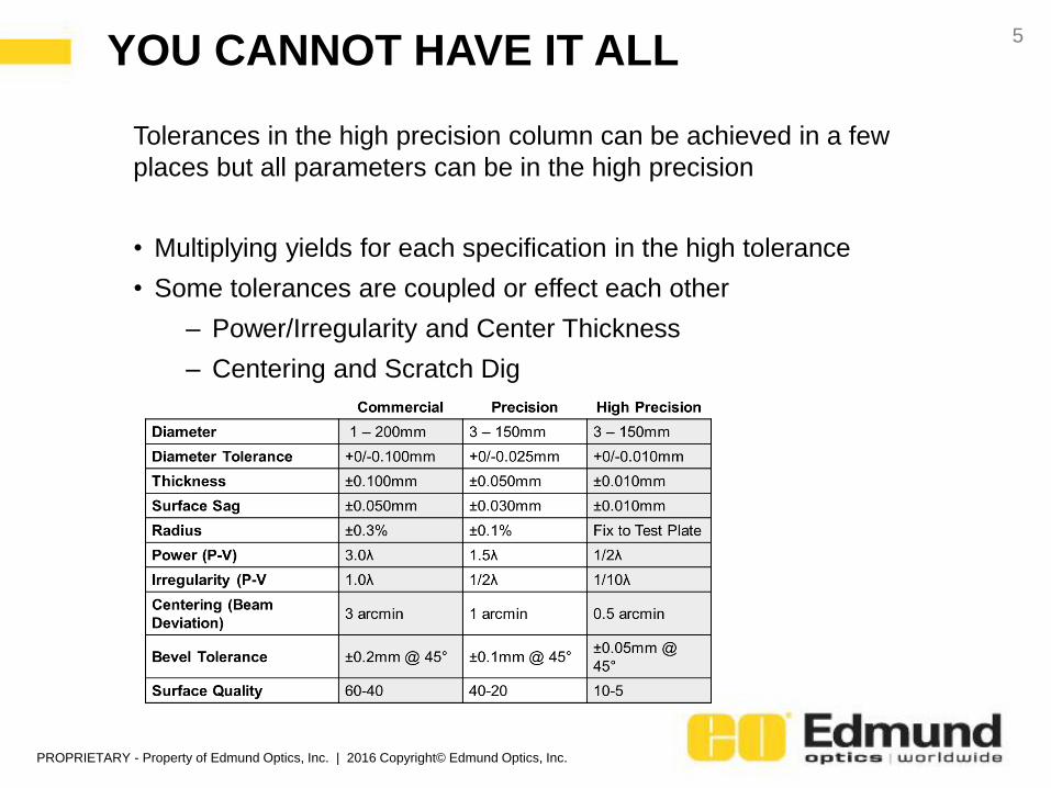
Tolerances in the high precision column can be achieved in a few
places but all parameters can be in the high precision
• Multiplying yields for each specification in the high tolerance
• Some tolerances are coupled or effect each other
– Power/Irregularity and Center Thickness
– Centering and Scratch Dig
PROPRIETARY - Property of Edmund Optics, Inc. | 2016 Copyright© Edmund Optics, Inc.
CONSTRAINING SHAPES SPRING RATIO6
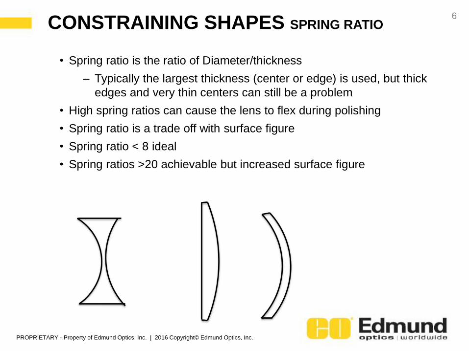
• Spring ratio is the ratio of Diameter/thickness
– Typically the largest thickness (center or edge) is used, but thick
edges and very thin centers can still be a problem
• High spring ratios can cause the lens to flex during polishing
• Spring ratio is a trade off with surface figure
• Spring ratio < 8 ideal
• Spring ratios >20 achievable but increased surface figure
PROPRIETARY - Property of Edmund Optics, Inc. | 2016 Copyright© Edmund Optics, Inc.
CONSTRAINING SHAPES Z- FACTOR7
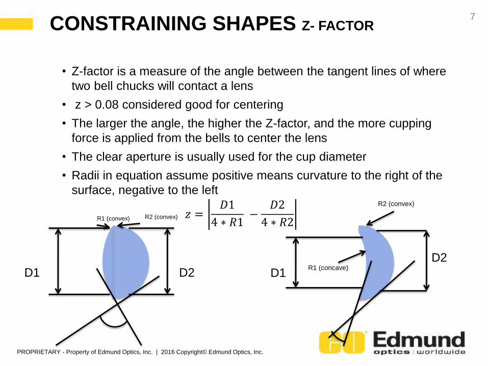
R1 (convex) R2 (convex)
D1 D2R1 (concave)
R2 (convex)
D1
D2
𝑧 =𝐷1
4 ∗ 𝑅1−
𝐷2
4 ∗ 𝑅2
• Z-factor is a measure of the angle between the tangent lines of where
two bell chucks will contact a lens
• z > 0.08 considered good for centering
• The larger the angle, the higher the Z-factor, and the more cupping
force is applied from the bells to center the lens
• The clear aperture is usually used for the cup diameter
• Radii in equation assume positive means curvature to the right of the
surface, negative to the left
PROPRIETARY - Property of Edmund Optics, Inc. | 2016 Copyright© Edmund Optics, Inc.
CONSTRAINING SHAPES CONCENTRIC RADII8
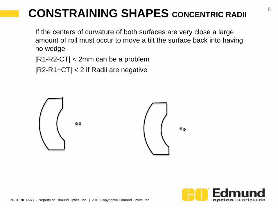
If the centers of curvature of both surfaces are very close a large
amount of roll must occur to move a tilt the surface back into having
no wedge
|R1-R2-CT| < 2mm can be a problem
|R2-R1+CT| < 2 if Radii are negative
PROPRIETARY - Property of Edmund Optics, Inc. | 2016 Copyright© Edmund Optics, Inc.
CONSTRAINING SHAPES CLEAR APERTURE9
Clear Aperture defines the area of the lens where the surface figure,
scratch-dig, and coatings are specified in.
There needs to be a margin between the clear aperture and the edge
of the lens.
This allows for many things:
• Room for bevels and the chip zone of the optic
• A place for coating fixture to hold the lens while the coating is being
applied
• This gives a place for the lens to be held without risking scratching
the surface during centering and other tests
• This helps account for the edge roll effect during polishing
• Typically a millimeter less than the diameter is needed as a maximum
but the more margin between the clear aperture and edge the better
for reducing costs
PROPRIETARY - Property of Edmund Optics, Inc. | 2016 Copyright© Edmund Optics, Inc.
CONSTRAINING SHAPES EDGE ROLL10
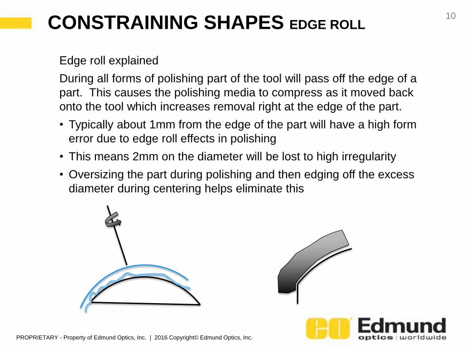
Edge roll explained
During all forms of polishing part of the tool will pass off the edge of a
part. This causes the polishing media to compress as it moved back
onto the tool which increases removal right at the edge of the part.
• Typically about 1mm from the edge of the part will have a high form
error due to edge roll effects in polishing
• This means 2mm on the diameter will be lost to high irregularity
• Oversizing the part during polishing and then edging off the excess
diameter during centering helps eliminate this
PROPRIETARY - Property of Edmund Optics, Inc. | 2016 Copyright© Edmund Optics, Inc.
CONSTRAINING SHAPES EDGE THICKNESS11
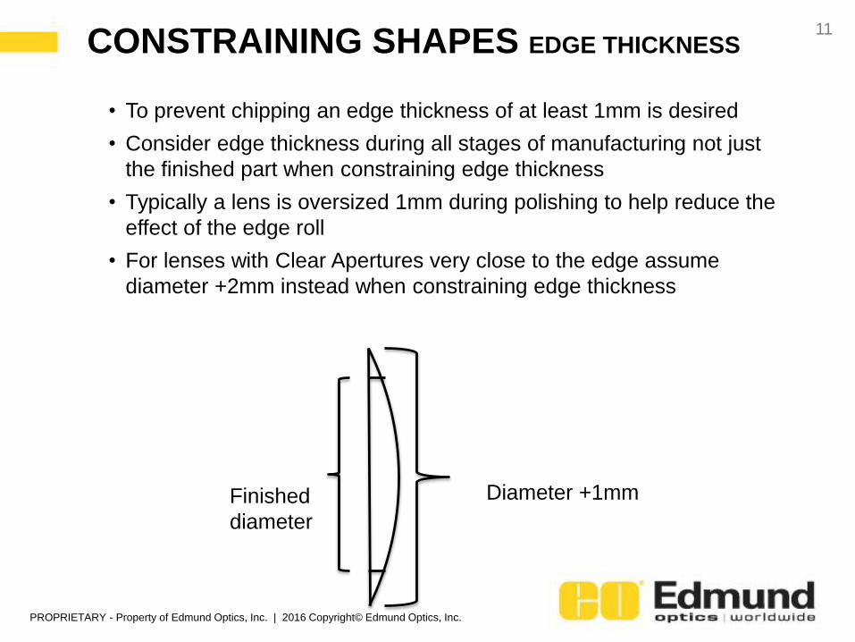
• To prevent chipping an edge thickness of at least 1mm is desired
• Consider edge thickness during all stages of manufacturing not just
the finished part when constraining edge thickness
• Typically a lens is oversized 1mm during polishing to help reduce the
effect of the edge roll
• For lenses with Clear Apertures very close to the edge assume
diameter +2mm instead when constraining edge thickness
Finished
diameter
Diameter +1mm
PROPRIETARY - Property of Edmund Optics, Inc. | 2016 Copyright© Edmund Optics, Inc.
HOW TO REMOVE SENSITIVITY12
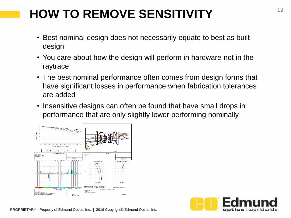
• Best nominal design does not necessarily equate to best as built
design
• You care about how the design will perform in hardware not in the
raytrace
• The best nominal performance often comes from design forms that
have significant losses in performance when fabrication tolerances
are added
• Insensitive designs can often be found that have small drops in
performance that are only slightly lower performing nominally
PROPRIETARY - Property of Edmund Optics, Inc. | 2016 Copyright© Edmund Optics, Inc.
HOW TO REMOVE SENSITIVITY 13
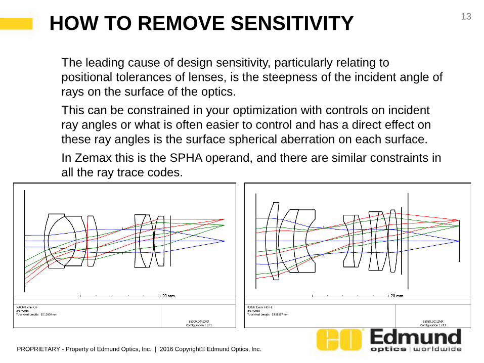
The leading cause of design sensitivity, particularly relating to
positional tolerances of lenses, is the steepness of the incident angle of
rays on the surface of the optics.
This can be constrained in your optimization with controls on incident
ray angles or what is often easier to control and has a direct effect on
these ray angles is the surface spherical aberration on each surface.
In Zemax this is the SPHA operand, and there are similar constraints in
all the ray trace codes.
PROPRIETARY - Property of Edmund Optics, Inc. | 2016 Copyright© Edmund Optics, Inc.
HOW TO REMOVE SENSITIVITY14
Another option for optimizing your design for insensitivity is to design
with perturbations in the design. Most codes now have automated
function like this that allow you do put a small amount of tilt, decenter,
and other tolerances into the design while it optimized to find the best
design after production tolerances. In Zemax this is the TOLR
operand. This often can take more time and requires more design effort
to achieve than the surface spherical method but many designers have
shown good success with this method as well.
PROPRIETARY - Property of Edmund Optics, Inc. | 2016 Copyright© Edmund Optics, Inc.
QUESTIONS?
15