Embed Size (px)
Citation preview

International Research Journal of Engineering and Technology (IRJET) e-ISSN: 2395 -0056
Volume: 04 Issue: 03 | Mar -2017 www.irjet.net p-ISSN: 2395-0072
© 2017, IRJET | Impact Factor value: 5.181 | ISO 9001:2008 Certified Journal | Page 2585
Design & Implementation of a practical EMI filter for high frequency-
high power dc-dc converter according to MIL-STD-461E
Ashish Tyagi1, Dr. Jayapal R.2, Dr. S. K. Venkatesh3, Anand Singh4
1 Ashish Tyagi, Student, EEE Dept., RVCE Bengaluru, India 2 Dr. Jayapal R., Head of Department, EEE Dept., RVCE Bengaluru, India
3 Dr. S. K. Venkatesh, Head of Department, Electrical Department, Center for Airborne Systems (CABS), DRDO Bengaluru, India
4 Anand Singh, Sc ‘D’, Electrical Department, Center for Airborne Systems (CABS), DRDO Bengaluru, India
---------------------------------------------------------------------***---------------------------------------------------------------------
Abstract - This paper presents approach of a practical design & implementation EMI-filter for high frequency and high power dc-dc converter, qualifying to the mil standard MIL-STD 461E. The conducted-emission (CE102) tests have been carried out as per the MIL-STD-461E. The current measurements are done instead of voltage measurements using current probe method; to distinguish between CM and DM noise components from the total conducted EMI. The EMI filter and dc-dc converter is then simulated in LTspice, using high-frequency equivalent model of CM-DM is used to calculate the CM-DM values. The proposed filter has been designed and implemented for a high frequency-power dc-dc converter which operates at a switching frequency of 250-300 kHz and with an output power of 500W. Then the practical considerations have been taken in component selection. The conducted emission (CE) tests were carried out on the hardware, to verify the design procedure and the implemented EMI filter prototype according to MIL STD 461E.
Key Words: Electromagnetic Interference, Common mode, Differential Mode, DC-DC Converter, EMI Filter.
1. INTRODUCTION
Electromagnetic interference(EMI), it has been the most occurring and major problem in power electronics converters, rapid changes in voltage and current within the switched mode power converters, makes these equipments the main source of radiated and conducted EMI to other nearby equipments. EMI is generally conductive in nature. The conducted emissions are mainly reduced by the EMI filters together with proper design of the circuit.[1]-[2]
Some of the issues related to EMC/EMI design for high frequency-power DC/DC convertor which is presented in the literature, in which the sources of EMI are discussed. Based on these discussions and observations suitable counter measures have been employed to reduce the noise level. A few methods for designing EMI filters for DC-line and AC converter applications have also been reviewed.[3]-[6] Practical measures for designing of the EMI filters for DC-DC
converter the differential mode and common-mode noise current measurements using a current probe method acc. to military standards (MIL-STD 461E)[7]-[9], have been presented in the paper. Hence a filter needs to be designed which meets low and high frequency specifications. When implemented and tested, some modifications are required, which is caused due to parasitic components. The equivalent circuits have been made with the noise modelled as the current source with constant impedance. Then the filter components are designed and calculated as per the required CM-DM attenuation.
In this paper, a design of EMI-filter and a practical approach for the design procedure is discussed for high-frequency, medium & high-power SMPS or dc-dc converter which can comply with the military standard, i.e., MIL-STD 461E. The MILSTD 461E calls for voltage measurements in the frequency range of 10 kHz to 30MHz, instead of this current measurement are taken at the LISN, the current probe measurement is used to separate the CM-DM noise plots. So the desired component values can be determined as per the CM-DM requirement. [10]
The EMI filter, LISN and the used DC-DC converter is simulated in LtspiceIV circuit has been made on the high-frequency based model including the ESR and ESL for selecting CM-DM filter components. A prototype has been designed and implemented for a dc-dc convertor, operating at a high switching frequency of 250 kHz and at a 500W output.[11] The practical implementation for the filter component selection and considerations shall be made in filter layout is also been discussed. The proposed EMI-filter design is verified experimentally by implementing hardware and simulations on LTspiceIV have been shown. Then the filter is tested and verified at the 270 VDC, 50Hz input and noise is checked at the LISN is under the limit line curve given by the military standard MIL-STD 461E.
2. EMI (NOISE) SOURCES & TOPOLOGY SELECTION
The main sources of EMI in dc-dc converters are due to di⁄dt and dv⁄dt during a switching period. [1] The conducted emissions are the major issue in most of the power electronic converters and it is caused by

International Research Journal of Engineering and Technology (IRJET) e-ISSN: 2395 -0056
Volume: 04 Issue: 03 | Mar -2017 www.irjet.net p-ISSN: 2395-0072
© 2017, IRJET | Impact Factor value: 5.181 | ISO 9001:2008 Certified Journal | Page 2586
Stray inductance of current loops causing high di⁄dt can create over voltages in high power dc-dc converters.
Stray capacitive coupling between windings and a frame resulting high dv⁄dt can create leakage current in magnetic elements and electric motors.
AC/DC motors.
Switch-mode power supplies (SMPS), due to high switching frequency and reverse recovery characteristics of diode.
Most of the electrical and electronic devices such as SMPS can generate EMI for other nearby components and which can damage the circuit or performance of the system can come down. In the used SMPS, a dc voltage is switched at a high frequency range from 200 kHz to 300 kHz; the efficiency of the high power switching power supplies will be high and compact in size. But these high speeds switching dc-dc power supplies are the major sources of EMI. The high frequency switching devices can generate unwanted EMI and downgrade the system performance. Mostly conducted EMI originates within SMPS from the switching devices such as MOSFETs, switching device, transformer and diodes. The ultimate goal of an EMI filter in power supplies is to minimize both internally and externally generated noises. [2]
2.1 EMI noise
It is an electrical noise or disturbance which downgrades the performance of the electrical system and nearby electronic devices by the way of conduction, electrostatic coupling, radiation or electromagnetic induction.
The types of EMI based on the source of generation,
Man-made EMI: It is usually generated from circuits; due to switching devices generate large spikes, etc.
Naturally occurring: It gets generated from natural source such as cosmic rays, lightning and other atmospheric noises.
The input EMI filters are used to limit inrush current and to reduce CS (conducted susceptibility) and suppress noise spikes. The maximum interference allowed is defined by the MIL-STD-461E and as can be seen in Fig.1, i.e., the basic curve for a 270V DC system. Fig.2 shows the DM & CM noise currents conducted through the EMI filters. The frequency range of EMI noise is
10 kHz to 30 MHz by conducted emission test.
30 MHz to 1 GHz by radiated emission test.
Fig.1- Conducted emission limit line according to MIL-STD
Modes of CE noise are two types:
Common mode (CM) EMI noise - line & neutral reference to ground.
Differential mode (DM) EMI noise - line to neutral.
Fig.2- CM and DM Noise Currents
For the designing of EMI filters which are mainly based on the EMI/EMC standards. The Department of Defense Interface standard has set the MIL-STD-461E for the conducted emission limits. The limits of conducted emission are in the frequency range of 10 kHz to 30 MHz for aircraft applications.
2.1 Topology Selection These types of EMI filter circuits can be diverse, they have the CM and DM filters which are based on the basic filtering circuits like: C, L, LC, CL, T, pi filter as shown in Fig.3. [5]

International Research Journal of Engineering and Technology (IRJET) e-ISSN: 2395 -0056
Volume: 04 Issue: 03 | Mar -2017 www.irjet.net p-ISSN: 2395-0072
© 2017, IRJET | Impact Factor value: 5.181 | ISO 9001:2008 Certified Journal | Page 2587
Fig.3- Topology and the attenuation in dB/decade
The various filtering circuits provide attenuation loss or insertion loss (IL):
i. L, C - 20 dB/decade,
ii. CL, LC- 40 dB/decade,
iii. Pi, T - 60 dB/decade.
Hence the topology chosen as pi topology to get higher attenuation loss, the noise which gets generated has to be suppressed and a block diagram of the test circuit is shown in Fig.4, the placement of EMI filter is shown with a LISN and a dc-dc converter.
Fig.4- Block diagram of the test circuit
2.2 Need for EMI Input Filter
All most everywhere in the high power circuits, they add an input EMI filter to suppress the noise. The purpose of EMI filter is to reduce the interference radiated or conducted by the high power circuit. All dc/dc power supply circuits or a system generates more electrical noise that cannot be filtered out by its own internal filter. The EMI issues can be resolved only by introducing an additional EMI filters at the source side of the power supplies. The main constraints / factors to be considered for the selection of EMI filters-
1. EMC/MIL Standards
2. Case Size
3. Operating voltage
4. I/O connections
5. Operating current (A)
6. Leakage current
7. DC resistance and Isolation resistance
8. High-voltage spike attenuation
9. Operating temperature (range)
10. Insertion loss (dB)
3. DESIGN CONSTRAINTS
The MIL-STD 461E has given preference for current measurements (CM) in spite of voltage measurements (VM), it is found useful to have a probe which measures current on flat range of 10 kHz to 30 MHz and can be used as a noise separator. Then the EMI noise ca and can be seen in terms of CM-DM noise components.
3.1 Measuring CM-DM components The noise measured has both the differential mode and common mode currents which needs to separated for proper designing of an EMI filter. To separate the total noise into DM and CM components, the output ports of the LISN are connected to the noise discrimination network shown below in the Fig.5.
Fig.5- Measuring CM and DM noise components
3.2 Setup (EMI measurements) The design of an EMI filter the required cutoff frequency (fc) information should be known. In this paper, the CM and DM cutoff frequencies are calculated and the noise levels of the converter have been measured by the current probe method through the conducted range of frequencies, before designing the filter a test shall be made to determine the CM-DM noise. The equipment used for the measurements are:
i. LISN as per mil standard
ii. Current probe, 10 kHz, and 30 MHz - flat response.
iii. Spectrum analyzer.
The measurements on the line and neutral will give a noise plot. However, these noise current data is not sufficient for the design EMI filter, since it is a mix of CM-filter components and DM-filter components. The values of these CM and DM component, it is needed to have information about both of the DM and CM noise data and the current probe configuration is as shown in Fig. 6 and Fig. 7 respectively.

International Research Journal of Engineering and Technology (IRJET) e-ISSN: 2395 -0056
Volume: 04 Issue: 03 | Mar -2017 www.irjet.net p-ISSN: 2395-0072
© 2017, IRJET | Impact Factor value: 5.181 | ISO 9001:2008 Certified Journal | Page 2588
Fig.6- CM conducted EMI measurement
Fig.7- DM conducted EMI measurement
4. DESIGN PROCEDURE The design of EMI-filter and its common mode, differential mode inductors, X and Y capacitors and a damping network has been added to suppress the impedance of the filter at certain higher frequencies. The CM and DM noise generated and separated using the discrimination network. The actual measured CM and DM waveforms shown in Fig. 8a and Fig. 8b
Fig. 8- a. CM noise curve, b. DM noise curve
(a) The CM and DM noise plot or current measurements as shown in Fig. then the CM-DM noise current are measured and can be shown in terms of equations:
During the CM measurements, the current measured: I measured = I phase + I neutral = (ICM + IDM) + (ICM - IDM)
= 2ICM (1)
During the DM measurements, the current measured: I measured = I phase - I neutral = (ICM + IDM) - (ICM - IDM)
= 2IDM (2)
(b) A 40 dB/decade slope-line tangent will give the cutoff frequencies as shown in Fig.9.
(c) Determine DM-filter components Ld and Cx: DM attenuation (DMattn) of the filter is as follows:
DMattn= ILISN (without filter)/ ILISN (with filter)
= (IS_DM)/ (IO_DM)
Fig.9- CM and DM noise-attenuation requirements
Then IoDM can be given as,
(4)
Where: ZL,DM=jωLDM, and Zc,DM=1/(jωCDM).
(5)
= 1 - ω2 LDM CDM
The corner frequency fcDM of single stage circuit is the frequency where: DMattn = 0:
fcDM = (6)
Where: LDM = 2LD and CDM = Cx, the circuit can be seen in Fig.10.

International Research Journal of Engineering and Technology (IRJET) e-ISSN: 2395 -0056
Volume: 04 Issue: 03 | Mar -2017 www.irjet.net p-ISSN: 2395-0072
© 2017, IRJET | Impact Factor value: 5.181 | ISO 9001:2008 Certified Journal | Page 2589
Fig.10- Schematic of the EMI filter with damping network
A compromise in selecting LD and Cx values, as large Ld requires bigger cores, which is difficult to design and requires more space. A larger Cx causes the self-resonance in circuit, which can lead to resonance problems; in return the filter provides gain instead of loss.
(d) Determine CM-filter components LC and CY: Using equations (3)–(6), the CM-filter components can be determined as:
fcDM = (7)
Where, CCM = 2 CY
Again, a compromise shall be made to design the CM values. CY can be chosen large as possible within military standards.
4.1 IMPLEMENTATION AND PRACTICAL CONSIDERATIONS
The hardware implementation is based on the practical approach to the selection of the proper component values for the EMI-filter inductor and the placement of the inductors and CM-DM components. The EMI filter requires soft cores that are driven into saturation slowly such that the filter components are selected as:
Design of CM Choke: The baseline design of the CM choke has been made by following the design example in [6]; later on some improvements will be made to take more parameters into account and to reduce its size. The first parameter that needs to be set is the wire size. If the current is supposed to be 2 A, the wire area and therefore the gauge of the wire could be found by assuming a current density and reading Table 1. If we follow the equation 8 and assume the current density to be 4 A/mm², then the gauge of wire required is AWG#20.
(8)
Table 1 AWG wire sizes
AWG
Gauge
Conductor
Diameter
(mm)
Conductor
Area (mm²)
14 1.628 2.08
15 1.450 1.65
16 1.291 1.31
17 1.150 1.04
18 1.024 0.823
19 0.912 0.653
20 0.812 0.518
21 0.729 0.410
22 0.644 0.326
The next step is to choose a core size and material depending on the number of turns needed. This part is an iterative process, since the chosen core may not allow enough space to wind the total number of turns. The “W” type of ferrite core, number ZW42508TC, is used for the design to achieve the number of turns required to get an inductance of 2.2mH. The winding used for the baseline CM choke is a single-layer structure. The main equations used to determine all the parameters are given below, and they provide a method for determining the inner circumference of the core (I.C), the maximum number of turns possible (Nmax), and the required number of turns for the design (Nrequired) winding σ represents the maximum angle that the winding subtends on half of the core. [4]- [5] It is common to assume 160° to allow some margin as shown in Fig. 11.
Fig.11- Winding angle example
(9)
With: AL: inductance factor (nH/ )
LCM: CM inductance (mH) If the formulas in eq. 9 are applied to the previous design, then the required number of turn is 13 turns for each side and the core size dimensions is shown in Fig.12.
International Research Journal of Engineering and Technology (IRJET) e-ISSN: 2395 -0056
Volume: 04 Issue: 03 | Mar -2017 www.irjet.net p-ISSN: 2395-0072
© 2017, IRJET | Impact Factor value: 5.181 | ISO 9001:2008 Certified Journal | Page 2590
Fig.12- Magnetics core size definition
Table 2 Magnetic core size Core Type A
(O.D.)
mm
B (I.D.)
mm
C (Height)
mm
AL (±30%)
nH/
ZW42508TC 25.34 15.45 9.95 9660
(10)
is verified.
4.2. HARDWARE IMPLEMENTATION, EXPERIMENTAL RESULTS AND WAVEFORMS
The hardware implementation of the proposed EMI filter with the proposed converter is shown in Fig.13. This is a two stage pi topology based EMI filter with a damping network which comprises of X – Capacitor’s, Y – Capacitor’s, differential and common mode inductors and the necessary compensation and protection circuit.
Fig. 13- Hardware implementation of the proposed EMI filter with converter
The setup used measuring the conducted emissions CE 102 is shown in the Fig.14 and the shown measurement setup comprises of a EUT table with proper grounding, LISN’s in both positive and negative line, 20dB attenuator is connected to the LISN to protect the spectrum analyzer from damaging. An attenuator reduces the power of a signal without appreciably distorting its waveform.
The equipment used for measuring the CE102 according to MIL-STD-461E is as- LISN as per mil standard 461E, 20dB attenuator, Current probe (10 kHz and 30 MHz), Spectrum analyzer, multimeter power sensors and power meter.
Fig.14- Test setup of the proposed EMI Filter with converter
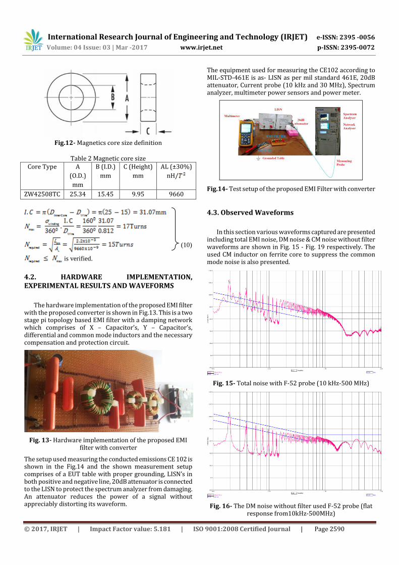
4.3. Observed Waveforms
In this section various waveforms captured are presented including total EMI noise, DM noise & CM noise without filter waveforms are shown in Fig. 15 - Fig. 19 respectively. The used CM inductor on ferrite core to suppress the common mode noise is also presented.
Fig. 15- Total noise with F-52 probe (10 kHz-500 MHz)
Fig. 16- The DM noise without filter used F-52 probe (flat response from10kHz-500MHz)

International Research Journal of Engineering and Technology (IRJET) e-ISSN: 2395 -0056
Volume: 04 Issue: 03 | Mar -2017 www.irjet.net p-ISSN: 2395-0072
© 2017, IRJET | Impact Factor value: 5.181 | ISO 9001:2008 Certified Journal | Page 2591
Fig.17- The CM noise without filter
The waveforms shown in Fig. 18 and Fig. 19 are the measured output waveform at the 50Ω termination of LISN and can be seen on the spectrum analyzer with the help of a flat response probe (10 kHz – 500 MHz).
Fig. 18- Total noise with filter on the positive line
Fig. 19- Total noise on negative line with filter
5. CONCLUSIONS Hence an approach to determine the EMI-filter components as per the MIL-STD 461E is presented based on CM-DM noise separation. For this a current probe method is used to separate CM-DM noise from actual noise waveforms and
then drawing a 40dB/decade tangent to get the desired cutoff frequency. Then the component values are designed according to the noise to be suppressed and a simulation model is tested and verified in LTspice IV including the ESR and ESL of the inductor and capacitor. An equivalent circuit is simulated with the CM and DM noise components. The filter performance is verified and implemented on the hardware. The proposed EMI filter is successfully implemented satisfying the specification requirements. The output voltage measured at 270V input voltage was 48V. The test result shows the noise or insertion loss v/s frequency curve is well below the MIL-STD-461E limit, it is concluded that adding an EMI filter with a switched mode power supply can lower the noise to qualify CE 102 military standard test.
REFERENCES [1] C. R. Paul, “Introduction to Electromagnetic
Compatibility”, Wiley New York, Second Edition, 1992.
[2] H. W. Ott, “Noise Reduction Techniques in Electronic Systems”, Wiley New York, Second Edition, 1988.
[3] I. Cardirci, B. Saka and Y. Eristiren, “Practical EMI Filter Design Procedure for High Power High Frequency SMPS According to MIL-STD 461”, IEE Proceedings - Electric Power Applications, vol. 152, no. 4, pp (775-782), July 2005.
[4] Abdolreza Esmaeli and Fazel Tavassoli, “Suppressing of common-mode voltage, shaft voltage, leakage current and EMI generated by voltage source PWM inverter”, International Electrical Engineering Journal (IEEJ), vol. 1 no. 1, pp. (529-535), February 2011.
[5] S. Ogasawara and H. Akagi, “Suppression of Common Mode Voltage in a PWM Rectifier/Inverter System”, IEEE Trans. Industry Applications, vol. 32, no. 5, pp. (1105-1114), July 1996.
[6] C. Khun, V. Tarateeraseth, W. Khan-ngern, Masaaki Kando, “A Simplified Active Input EMI Filter of Common-mode Voltage Cancellation for Induction Motor Drive”, The ECTI International Conference (ECTI-CON), Japan pp. (172-177), February 2007.
[7] RTCA, Inc., “Environmental Condition and Test Procedure for Airborne Equipment”DO-160D, Dec 2004.
[8] Department of Defense, “Requirement for the Control of Electromagnetic Interference Characteristics of Subsystems and Equipment”, Military Standard 461E, Aug 1999.
[9] Y. C. Son, S. K. Sul, “A Novel Active Common-mode EMI Filter for PWM Inverter”, Proc. APEC 2002, Nagaoka, pp. (545-549), March 2002.
[10] W. Chen, X. Yang and Z. Wang, “An Active EMI Filtering Technique for Improving Passive Filer Low Frequency Performance”, IEEE Transactions on Electromagnetic Compatibility, vol. 48, no. 1, pp. (172- 177), February 2006.
[11] F. Shih, D. Chen, Y. Wu, and Y. Chen, “A Procedure for Designing EMI Filters for AC Line Applications”, IEEE Transactions on Power Electronics, vol. 11, no. 1, pp. (170 – 181), January 1996.