Embed Size (px)
Citation preview
©2000 The Reinforced Earth Company. This manual is the property of The Reinforced Earth Company. Any reproduction or distribution without the express written consent of RECo is prohibited.
DESIGN MANUAL
For Reinforced Earth® Walls
The Reinforced Earth Company 8614 Westwood Center Drive, Suite 1100, Vienna, VA
22182-2233
Phone 703-821-1175 / Toll Free 800-446-5700 Fax 703-821-1815
OCT 2005
©2000 The Reinforced Earth Company. This manual is the property of The Reinforced Earth Company. Any reproduction or distribution without the express written consent of RECo is prohibited.
TABLE OF CONTENTS 1.0 INTRODUCTION 2.0 STANDARD REFERENCES 3.0 TERMINOLOGY 4.0 GENERAL DESIGN 4.1 Description of a Reinforced Earth Wall 4.1.1 Structural Applications 4.1.2 Advantages 4.1.3 Service Life 4.2 Design Information Needs 4.2.1 Project Description/Location 4.2.2 Geotechnical Report 4.2.3 Normal Pool/Flood Levels 4.2.4 Service Life 4.3 Loading Conditions 4.3.1 Static Loads 4.3.2 Seismic Loads 4.3.3 Special Loading Conditions 5.0 MATERIALS 5.1 Backfill 5.1.1 Select Backfill 5.1.2 Random Backfill 5.1.3 Random Backfill placed Against a Cut Slope 5.2 Reinforcing Steel 5.2.1 Tensile Capacity 5.2.2 Pullout Capacity 5.2.3 Durability 5.3 Facings 5.4 Connections 5.5 Bearing Pads 5.6 Filter Cloth 6.0 STABILITY 6.1 External Stability 6.1.1 Sliding and Overturning 6.1.2 Embedment 6.2 Internal Stability 6.2.1 Reinforcement Type 6.2.2 Reinforcement Length
©2000 The Reinforced Earth Company. This manual is the property of The Reinforced Earth Company. Any reproduction or distribution without the express written consent of RECo is prohibited.
6.2.3 Spacing of Reinforcement 6.3 Overall (Global) Stability 7.0 FOUNDATION CONSIDERATIONS 7.1 Bearing Capacity of the Foundation Soil 7.2 True Abutment Bearing Capacity 7.3 Total Settlement 7.4 Differential Settlement 7.5 Foundation Stabilization Methods 8.0 WALL CONSTRUCTION DRAWINGS AND GENERAL DETAILS 8.1 General Notes 8.2 Elevation 8.3 Typical Sections 8.4 Typical Panel and Connection Details 8.5 Reinforcing Strips 8.6 Leveling Pad Steps 9.0 TYPICAL DESIGN DETAILS 9.1 Slip Joints 9.2 Butt Joints 9.3 Corner Elements 9.4 Coping 9.5 Slope-top Panels 9.6 Connections 9.7 Traffic Barriers 9.8 Parapets 9.9 Bridge Seats 9.10 Horizontal Inclusions (Drainage Structures, Pipelines, etc.) 9.11 Vertical Inclusions 9.12 Drainage Details 9.13 Acute Corners 9.14 Curves 9.15 Tiered Walls
Page 1-1
1.0 INTRODUCTION Welcome Welcome to the Design Manual for Reinforced Earth® Walls. This manual will explain what a Reinforced Earth wall is and how it works, as well as outline the many ways your projects can benefit from this technology. The Manual also defines and discusses the information needed for the design of a Reinforced Earth retaining wall. It includes an extensive glossary and numerous references to enhance your knowledge of this exciting and versatile earth retention system. What Are Reinforced Earth Walls? Reinforced Earth retaining walls are an economical way to meet every-day earth retention needs for highway and bridge grade separations, railroads and mass transit systems, waterfronts, airports, loading docks, industrial facilities and commercial and residential developments. They are also used in response to difficult design conditions such as very high structures, restricted space, unstable slopes and poor foundation conditions. The inherent strength and flexibility of the overall wall system gives designers a powerful way to economically solve difficult stability issues for structures subject to flooding or other hydrodynamic forces, or those in seismically active areas. How Do I Obtain a Reinforced Earth Design? The Reinforced Earth Company (RECo) pioneered this technology and developed it over the last 30 years to a meet a wide variety of project requirements. Since specific project information is always required to arrive at a safe and economical solution, applying Reinforced Earth technology is a collaborative effort involving the Owner and/or the Owner’s Consultant and The Reinforced Earth Company (RECo). This Manual is written not only to help you understand Reinforced Earth technology and terminology, but also to identify the information that RECo needs from you in order to complete a design. There is nothing mysterious about designing a Reinforced Earth wall, but the best and most economical designs are always the result of experience and judgment. That is why RECo provides complete Reinforced Earth wall designs, enabling you to benefit from our experience. Since we do the design, this Manual is not intended to train you to design Reinforced Earth walls. Instead, it will help you identify situations on your project where a Reinforced Earth wall is technically appropriate and help you understand the wall drawings you receive from us. It will also allow you to do a preliminary sizing of the structure and enable you to understand and estimate not only the loads that a Reinforced Earth structure can carry, but also the loads the Reinforced Earth structure will apply to the site where it is built.
Page 1-2
Organization and Numbering System of this Manual This manual has nine sections including this Introduction. The other sections are Standard References, Terminology, General Design, Materials, Stability, Foundation Considerations, Wall Construction Drawings and Typical Design Details. The sections are numbered 1 through 9, with subsections designated by decimal points, i.e., Section 5.2, with figures at the end of each section for easy reference. Following this format, the figures for Section 5.2 are numbered Figure 5.2.1, Figure 5.2.2, etc. If a section has a three-digit designation, as does Section 6.2.3, then the matching figure number has four digits, i.e., Figure 6.2.3.1. The last digit of the figure number is always that figure's sequence number within the section. Although we hope you will read this manual completely, we understand you may refer only to a particular section to answer a question about a project. Therefore, we have tried to make each section of text as nearly self-contained as possible so you can easily get the information you need. Inevitably, this leads to some repetition that you may encounter if you read several sections or chapters at once. Please let this repetition suggest the importance of the information and use the repetition to help you better understand the information presented. A Note about Dimensions This manual uses Metric dimensions, with the English (Imperial) conversion following in parentheses. This convention is used in both the text and the figures. Although in most cases the Metric dimension is more precise than the converted Imperial dimension, the dimensions used are for illustrative purposes only and may vary slightly from precise design or fabrication dimensions due either to conversion or to simplification appropriate to the guideline character of this manual. Therefore, when required for design, precise dimensions should always be obtained from contract plans or directly from The Reinforced Earth Company. RECo reserves the right to change the dimensions of fabricated materials as needed. Your Feedback is Welcome This document is intended to be user friendly, and we welcome your feedback about improvements that will make it even more so. We expect to issue additions and revisions to this manual as our technology advances, as well as in response to your feedback. Whether you use it as a quick reference or as a frequent guide, we hope this Design Manual for Reinforced Earth Walls helps you reach your design goals on every project.
Page 2-1
2.0 STANDARD REFERENCES Reference is made throughout this manual to the following reports, specifications, textbooks and Reinforced Earth Company technical bulletins (detailed references to section or page numbers are given in the text): Construction and Quality Control Manual for Reinforced Earth Structures, The Reinforced Earth Company, 1996, Section D - Backfilling. Durability/Corrosion of Soil Reinforcement Structures, Federal Highway Administration Report FHWA-RD-89-186, 1990. In Situ Soil Improvement Techniques, AASHTO-AGC-ARTBA Joint Committee, Subcommittee on New Highway Materials, Task Force 27 Report, 1990. Soil Mechanics and Engineering Practice, Second Edition, Karl Terzaghi and Ralph B. Peck, John Wiley & Sons, 1967. Standard Specifications for Highway Bridges, AASHTO*, 1996 (Sixteenth Edition), 1998 Interim, Division I - Design, Section 5.3. Standard Specifications for Highway Bridges, AASHTO, 1996 (Sixteenth Edition), 1998 Interim, Division I - Design, Section 5.8. Standard Specifications for Highway Bridges, AASHTO, 1996 (Sixteenth Edition), 1998 Interim, Division I – Design, Section 10.32. Standard Specifications for Highway Bridges, AASHTO, 1996 (Sixteenth Edition), 1998 Interim, Division II - Construction, Section 7.3.6.3. Subsurface Investigation and Improvements for MSE Structures Constructed on Poor Foundation Soils, The Reinforced Earth Company, undated. Technical Bulletin MSE-1, Service Life, Allowable Reinforcement Stress and Metal Loss Rates to be Used in the Design of Permanent MSE Structures, The Reinforced Earth Company, 1992, revised 1995. Technical Bulletin: MSE-6, Apparent Coefficient of Friction, f*, to be Used in the Design of Reinforced Earth Structures, The Reinforced Earth Company, 1995 Technical Bulletin MSE-7, Minimum Embedment Requirements for MSE Structures, The Reinforced Earth Company, 1995. * American Association of State Highway and Transportation Officials
Page 3-1
3.0 TERMINOLOGY The following terms are defined for use in this manual: - Symbol for friction angle. - Symbol for unit weight or density. AASHTO – American Association of State Highway and Transportation Officials. Acceleration Coefficient – Coefficient based on seismic activity for a specific location. Active Earth Pressure Coefficient, Ka – Coefficient based on the increase of horizontal pressure, as determined by the formula tan2 (45 - / 2). Active Zone – The region behind the facing of a Reinforced Earth wall in which the shear stress along the reinforcing strips is directed toward the facing. In cross section, the width of the active zone varies from zero at the toe of the structure to 30% of the structure height from mid-height of the wall to the top of the wall. Acute Corner – A corner formed by two segments of a Reinforced Earth wall that meet and form an angle less than or equal to 90o, as measured from the fill side of the wall. Allowable Bearing Pressure - Ultimate bearing capacity of foundation soil reduced by applying a factor of safety. Allowable Tensile Strength – The portion of a material's ultimate tensile strength that may be used for design. Allowable tensile strength is determined from the yield (or ultimate) strength, reduced by a specified factor of safety and by a reduction in cross sectional area to account for service life losses. Ap – Symbol for tributary wall area. Applied Bearing Pressure – Pressure applied to foundation soil by the structure being supported. As – Symbol for cross-sectional area of steel. ASTM – American Society for Testing and Materials. At-Rest Earth Pressure Coefficient, Ko - Coefficient based on the horizontal pressures needed to remain at rest, as determined by the formula 1-sin. B – Symbol for bearing width (at base of wall, measured on the wall cross section).
Page 3-2
Backfill – Soil fill placed behind a structure or replaced in an excavation. Bishop’s Modified Method of Slices – One of the common methods used to determine global stability. Black steel – Bare steel without galvanization or other coating. Boussinesq Pressure Distribution – Method of distributing foundation load through a soil mass based on the size and shape of the foundation. Bridge Seat – Reinforced concrete cap that supports bridge beams and transfers loads to foundation soils or deep foundation elements. Broken Back Slope – Slope climbing from the top of a wall and leveling out at a distance from the front face no greater than twice the height of the wall. Bearing Capacity (Terzaghi) – Method of determining ultimate bearing capacity of foundation soil. Butt Joint - Vertical break in a wall face where wall may change direction (wall panels are not connected across the joint). Cast-In-Place (CIP) Concrete – Concrete poured on-site in the location of intended use. Cheekwall – Closure wall at the end of a bridge abutment. Cl – Chemical symbol for chlorides. Coefficient of Sliding (soil to soil) - Frictional resistance of soil determined by the term tan, where is the friction angle of the soil. Cohesion – Strength characteristic of soils determined by the intercept of the shear strength at zero normal stress on the Mohr Coulomb envelop (see also Friction Angle). Cohesionless Soils – Soils exhibiting strength primarily through friction between soil particles; granular soils. Cohesive Soils – Soils exhibiting strength primarily through cohesion; fine-grained soils. Consolidation Settlement – Settlement occurring over time as void space between soil particles in the soil mass decreases. Coping – Precast or cast-in-place units used as top treatments for walls. Corner Element – Specialized precast facing units that change wall alignment at a particular point.
Page 3-3
Corrosion – Process of oxidation in metallic reinforcing strips that leads to loss of thickness. Coulomb Method – More detailed earth pressure theory than Rankine Method; based on density of retained soil, friction angle of retained soil, height of wall, friction between soil and wall, and angles of repose of wall and retained slope. Critical Structure – A structure with a design life of 100 years, such as a bridge abutment or a structure supporting a railroad; a structure that performs a critical function where failure would have unacceptable consequences; a structure that has been designated critical by the owner. Cruciform Panel – Cross-shaped precast panels used as one type of facing for Reinforced Earth walls. Density of Reinforcing Strips – Number of reinforcing strips within a given wall face area (generally an area of 2.25 sm [24.2 sf]). Differential Settlement - Settlement difference between two points located a known distance apart. Direct Shear Test – Laboratory test to determine the 2-dimensional shear strength of a soil at a particular normal load, thereby also determining the friction angle and cohesion. Dunois Coating – Thermal sprayed alloy coating composed of 85% zinc and 15% aluminum. Eccentricity – Offset from the center of mass of the resultant force due to external loading. Effective Length – The length of earth reinforcement that is outside the active zone and into the resistive zone. Embedment – Depth from ground surface to the top of the leveling pad of a Reinforced Earth wall. EPDM Rubber – Elastomer used to manufacture bearing pads for use between panels of a Reinforced Earth wall. External Stability – Stability conditions that are external to the reinforced volume and affect the structure; includes overturning and sliding. f* – "Apparent coefficient of friction" Frictional interaction between soil type and reinforcement in Reinforced Earth wall.
Page 3-4
Factor of Safety – In global stability applications, the sum of the resisting forces divided by the sum of the driving forces. In any situation, the amount by which resisting forces exceed driving forces, expressed as a ratio in decimal number format. Filter Cloth – Geosynthetic fabric used to cover the backside of the panel joints of Reinforced Earth walls to contain backfill while allowing drainage. Fines – Soil particles passing a US Standard No. 200 sieve (75m). Finished Grade – Final elevation of ground surface for a given location of construction. Finite Element (Method) – Two or three-dimensional modeling method that evaluates soil/structure interaction by dividing the soil and/or structure into discrete elements and identifying and analyzing physical characteristics of these elements. Friction Angle – Angle determined by an envelope plotting shear strength versus normal stress in laboratory testing, as determined by Mohr-Coulomb theory. Frost Heave – Expansion of soil due to freezing. Fy – Symbol for yield strength of steel. Geosynthetic – The generic term for all synthetic materials used in geotechnical engineering applications, including geotextiles, geogrids, geonets, geomembranes and geocomposites. Geotechnical (Engineering) – Civil engineering discipline devoted to evaluation of properties of soil and rock and to their interaction with engineered structures. Global Stability – Mass stability of entire embankment and foundation external to Reinforced Earth structure. Gravity Retaining Structure – A retaining structure that transfers gravitational and applied loads directly into the soil or rock foundation, without the use of piles or other deep foundation elements. Granular Backfill – Backfill meeting the physico-chemical requirements specified for Reinforced Earth wall applications (also referred to as "Select Backfill"). Gutter Line - Base elevation of gutter located at top of wall. H – Symbol for wall height (measured from top of leveling pad to top of wall panels). H' – Symbol for height from top of leveling pad to top of broken back slope surcharge.
Page 3-5
h – For walls with sloping fill on top of wall, symbol for height measured to point where surface of sloping fill intersects vertical line rising from back end of reinforcing strips. HA - symbol for "High Adherence," describing the surface characteristics of ribbed or ladder reinforcing strips. HA Ladder – A high adherence (HA) reinforcing element used to add tensile strength to the soil in a Reinforced Earth wall. The HA ladder is 50 mm wide and formed from W10 wires. Hairpin Connection – Type of connection used with HA strips or HA ladders in wire-faced wall construction. Handlebar Connection – Type of connection used with ladder reinforcements in wire-faced wall construction. Horizontal Inclusion – Structure that extends horizontally through (Reinforced Earth) backfill such as a pipeline or a drainage structure. Hydrostatic Pressure – Pressure resulting from water. Differential hydrostatic pressure results from different water level heights in front of, inside or behind a structure. Immediate Settlement – Settlement of a structure that coincides in time with its construction. Inclusion (Horizontal) – See Horizontal Inclusion. Inclusion (Vertical) – See Vertical Inclusion. Inextensible – Term applied to materials such as steel reinforcing strips that deform much less readily than does the backfill in which they are embedded. Internal Stability – Stability conditions affecting the Reinforced Earth volume, including reinforcement pullout and tensile resistance. Ka, Active Earth Pressure Coefficient – Coefficient based on the increase of horizontal pressure, as determined by the formula tan2 (45 - / 2). Ko, At-Rest Earth Pressure Coefficient - Coefficient based on the horizontal pressures needed to remain at rest, as determined by the formula 1-sin. L – Symbol for length. Ladder Reinforcements – Earth reinforcements consisting of two longitudinal wires with cross-wires at regular intervals. Two types are used in Reinforced Earth walls – HA Ladders and Wide Ladders (see individual definitions).
Page 3-6
Large Rectangular Panels – Panels measuring 1.5 meters high by 3 meters wide; one type of facing for Reinforced Earth walls. Leveling Pad – Lean concrete pad used as a smooth working surface on which to set the first level of precast panels when constructing a Reinforced Earth wall. Live Load – Load applied to a structure, where the load does not remain stationary and may vary in magnitude. Magnesium sulfate soundness – Laboratory test used to determine durability of soil. Marginal Soils – Soils that may not readily support the loads applied by certain structures. MSE – Mechanically Stabilized Earth. N – Number of reinforcements in a given tributary area of a Reinforced Earth wall. Normal Pool/Flood Level – Statistically derived standard (normal) water level and elevated (flood) water level for a specific location. Open-Graded Aggregate – Crushed stone or gravel with a low percentage of sand, silt or clay (usually less than 10% by weight). Overturning – Outward rotation of the top of a gravity structure. P – Symbol for pullout capacity of reinforcements. Parapet - Precast or cast-in-place concrete barrier or rail located on top of a Reinforced Earth wall. Particle size – The diameter of a soil particle in backfill. PC (Point of Curvature) – Geometric starting point of a curve. pH - Scale used to indicate the acidity (range 0 to 7) or alkalinity (range 7 to 14) of soil. Physico-chemical Requirements – Requirements for the physical, chemical and conductive characteristics of soil backfill used in Reinforced Earth wall applications. Plasticity Index – Soil parameter determined in a laboratory by the Atterberg test technique showing the difference in water content for a soil in its liquid limit state compared to the same soil in its plastic limit state. Pore Water – Water occupying the void space between particles in a soil mass.
Page 3-7
Precast Concrete – Concrete cast at a plant in standard shapes, such as panels and coping, for shipment and installation at project sites. PT (Point of Tangency) – Geometric end point of a curve. PVC – Polyvinyl chloride. Radius of Curvature – Geometric distance from center of radius to associated curve. Random Backfill – Backfill located outside the reinforced volume of a Reinforced Earth wall. Rankine Method – Simplified earth pressure theory based on the density of the retained soil, the height of the wall and the friction angle of the retained soil. RECo – The Reinforced Earth Company. Reinforced Earth Wall – Mechanically Stabilized Earth wall system consisting of precast concrete facing panels, metallic reinforcing strips and granular backfill. Reinforcing Bar (Rebar) – Steel bar used in structural concrete to provide tensile strength. Reinforcing Strip – A high adherence (HA) reinforcing element used to add tensile strength to the soil in a Reinforced Earth wall. The HA reinforcing strip is 50 mm wide by 4 mm thick, with 3 mm high ribs on both the top and bottom surfaces. Resistivity – Resistance of saturated soil to passage of electrical current. Resistive Zone – The region behind the active zone in which the shear stress along the reinforcing strips is directed away from the facing. Sacrificial Thickness – Portion of a reinforcing strip's thickness expected to be sacrificed to corrosion during the design life of the structure. Scour Protection – Stabilization material such as stone or riprap placed along the base of a waterfront structure to prevent undermining and collapse from tides or current. Select Backfill – Backfill meeting the physico-chemical requirements specified for Reinforced Earth wall applications (also referred to as "Granular Backfill"). Service Life – The number of years a structure is expected to remain in service and fully functional. Specifically, the period of time during which the structural components must remain in an allowable stress condition (generally 75 or 100 years). Sh – Symbol for horizontal earth pressure at specific level within a wall.
Page 3-8
Shear strength – The resistance of a soil to shear. Shop Drawings – Drawings prepared to show the dimensions and materials necessary to fabricate the components of a Reinforced Earth wall. Slip Joint – Continuous vertical joint placed in a Reinforced Earth wall to allow differential settlement without facing panel distress, to create a transition from a cast-in-place to a Reinforced Earth structure, or to accommodate a small-radius curve. SO4 – Chemical symbol for sulfates. Soil Cement – a mixture of soil and cement used to stabilize weak soils under certain conditions. Soil Dilatency – The tendency of a granular soil to experience a volume increase during shearing of the soil. Splice Plate – Steel plate used to connect two reinforcing strips when the design length is in excess of manufacturing limits. STABL – Software developed by Purdue University to determine global stability in accordance with Bishop’s Modified Method of Slices. Stepped – The use of panels of varying heights at either the base or top of a Reinforced Earth wall to accommodate elevation changes. Sv – Symbol for vertical stress due to overburden soil above a reinforcement in Reinforced Earth volume. T90 – In evaluation of consolidation, the time it takes for 90% of settlement to occur in a soil mass. Terratrel - Wire-faced Reinforced Earth wall system developed by RECo. Terzaghi Bearing Capacity – Method of determining ultimate bearing capacity of foundation soil. Tie Strip – Steel anchoring device cast into precast panel so reinforcing strip may be attached for Reinforced Earth wall construction. Tiered Walls – Reinforced Earth walls stacked atop each other and with each higher wall stepped back behind the one below (rather than a single vertical wall face). Toe of Wall – Point at the base of the front face of the Reinforced Earth wall panels at the top of the leveling pad.
Page 3-9
Traffic Barrier – Precast or cast-in-place barrier placed at top of wall for crash protection. Triaxial Test – Laboratory test used to determine the 3-dimensional shear strength of soil at a particular normal load and confining pressure, thereby finding the friction angle and cohesion. True Bridge Abutment – Type of Reinforced Earth wall where the bridge foundation is a spread footing supported directly on top of the Reinforced Earth volume. Unit Weight – Density of soil or other material. Vertical Inclusion – Structure that extends vertically through (Reinforced Earth) backfill, such as a bridge abutment pile, a manhole or a large sign foundation. Wick Drain – Synthetic strip with open passageways, installed in soil to relieve pore water pressure during surcharge loading. Wide Ladder – A reinforcing element used to add tensile strength to the soil in certain types of Reinforced Earth walls. The wide ladder is 180 mm (7 in) wide and formed from W7 wires. z – Symbol for depth.
Page 4-1
4.0 GENERAL DESIGN
4.1 Description of a Reinforced Earth Wall A Reinforced Earth wall is a coherent gravity mass that can be engineered to meet specific loading requirements. It consists of precast concrete facing panels, metallic (steel) soil reinforcements and granular backfill. Its strength and stability are derived from the frictional interaction between the granular backfill and the reinforcements, resulting in a permanent and predictable bond that creates a unique composite construction material.
4.1.1 Structural Applications Reinforced Earth is used in urban, rural and mountainous terrain for
Retaining Walls Seawalls Bridge Abutments Submerged walls Railway Structures Truck dumps Dams Bulk storage facilities
4.1.2 Advantages The advantages of Reinforced Earth technology include
Flexibility - Reinforced Earth structures distribute loads over compressible soils and unstable slopes, reducing the need for deep foundations
High load-carrying capability, both static and dynamic - applied structural loads
are distributed through the compacted granular fill and earth pressure loads are resisted by the gravity mass
Ease and speed of installation - prefabricated materials and granular soil simplify
construction and minimize the impact of bad weather Pleasing appearance - panels may be given a variety of architectural treatments Economy - 15-50% savings over cast-in-place concrete walls, depending on wall
height and loading conditions.
Page 4-2
4.1.3 Service Life What is service life? The service life of a Reinforced Earth structure is the period of time during which the structure must remain in an allowable stress condition (see Section 4.2.4 for a more complete discussion of service life). Information about the service life must be provided by the Owner or engineer in order for The Reinforced Earth Company to properly design the structure. If the service life is not specified, the typical value of 75 years will be assumed.
4.2 Design Information Needs
4.2.1 Project Description/Location What information is needed to lay out a Reinforced Earth wall?
Plan view showing wall location relative to roadway centerline, bridges, piles, existing retaining walls, slopes or other objects. Ideally, the plan view should include offsets from the face of the wall to the centerline, the beginning and ending wall stations, and the roadway geometry.
Location and sizes of inlets, pipes, signs and light poles, existing or future, which
will impact the design of the Reinforced Earth structure. Typical cross section at the wall location with all appropriate dimensions. Top of wall elevations and bottom of wall or finished grade elevations (and/or
embedment criteria). Vertical curve and superelevation data and cross sections at the wall location can substitute for wall elevations.
What details should be provided in the contract documents regarding a Reinforced Earth wall? Most details needed to construct a Reinforced Earth wall will be provided in the wall plans prepared by RECo. Details regarding drainage, illumination, sign supports and top of wall appurtenances should be provided by the Owner in the contract documents.
Page 4-3
4.2.2 Geotechnical Report What is the importance of a geotechnical report in the design of a Reinforced Earth structure? Geotechnical information is critical to evaluating foundation conditions for any structure, even a flexible one like a Reinforced Earth wall. As always, the more complete and better quality the geotechnical data, the less conservative and more economical the foundation design can be, and the structure itself can reflect this economy as well. This is especially true in these situations:
When weak soils underlie the project site. In such situations, a Reinforced Earth wall is often an economical choice specifically because it is flexible and can adjust to the settlement that sometimes occurs with weak soils, eliminating the need for deep or massive foundations intended to provide rigidity.
When the Reinforced Earth structure will support a deformation-sensitive structure
such as a bridge abutment. It is often more economical to make (at least the end span of) a bridge superstructure flexible than it is to make the substructure rigid. Thus, having good geotechnical data is critical to making informed structure design decisions.
These situations and others are discussed in more detail in Section 7, Foundation Considerations. The bottom line, however, is that more (rather than less) geotechnical information is always a wise investment. What type of information is needed from a geotechnical report? A geotechnical report should provide specific information about the conditions at the project site. Typically, borings should be taken to a depth 1.5 to 2 times the wall height, or to bedrock, whichever is encountered first. They should be located at no greater than 60 m (200 ft) intervals and/or near the ends of each structure. Closer spacing or greater depth of borings may be required by field conditions or Owner specifications. Alignment of borings along (or slightly behind) the proposed wall face is preferred. In the case of weak foundation soils, shear strength and settlement characteristics are of major importance. If these characteristics are well defined in the geotechnical report, the RECo designer will not be forced to make conservative assumptions. For more specific recommendations on the subsurface soil exploration and laboratory testing program, see Reference 5.
Page 4-4
What is the relationship between the coefficient of sliding and the friction angle of the foundation soil? Most geotechnical reports provide information about the coefficient of sliding between the proposed footing concrete and the underlying soil, to be used for designing traditional reinforced concrete retaining walls. For sliding of a Reinforced Earth wall to occur, however, a sliding plane must develop either between the Reinforced Earth backfill and the foundation soil, or totally within the foundation soil itself. Therefore, the friction angles of both the Reinforced Earth backfill and the foundation soil must be known. A reasonable estimate of the friction angle of the specified Reinforced Earth backfill can be made based on experience with other materials complying with the same granular specification, but laboratory testing is required to determine the friction angle (shear strength) and cohesion of the (site-specific) foundation soil. How is Equivalent Fluid Pressure used in the design of Reinforced Earth walls? Equivalent fluid pressure, a concept used in the design of concrete retaining walls, is not applicable to the design of Reinforced Earth walls. Reinforced Earth design procedures require calculation of the actual vertical and horizontal earth pressures to determine the load carried by the reinforcing strips and the pressure at the back face of the wall.
4.2.3 Normal Pool/Flood Levels What is the importance of pool elevation and/or flood level information for a Reinforced Earth structure? Information about normal pool and flood levels is of major importance. If the structure is partially or substantially submerged, buoyant forces must be accounted for in design. Under these circumstances, a Reinforced Earth structure will exert less pressure on the subsoil, thereby reducing the factors of safety against sliding and overturning. Therefore, a submerged condition affects the overall stability of a Reinforced Earth structure and must be accounted for in design. What is a "periodically submerged" structure? Periodically submerged Reinforced Earth structures are those subject to periodic fresh water flooding, with the cumulative submerged time no more than two weeks per year. In this situation, the Reinforced Earth structure is designed with drainage features appropriate to the 100-year (or other specified) flood condition, as discussed in the next paragraph. Additional information on submergence and hydrostatic loading is contained in Section 4.3.3.
Page 4-5
In a rapid drawdown situation (pool elevation drops faster than water can flow out through the panel joints), water temporarily trapped behind the wall panels can create an unbalanced head condition and reduce the factor of safety in relatively fine-grained (sandy to silty) backfills. For such structures along rivers and canals, AASHTO Section 5.8.12.3 requires that a minimum differential hydrostatic pressure equal to 1.0 m (3.3 ft) of water be considered in design. To reduce problems associated with submergence, it is recommended to use completely free draining (coarse) select backfill for such Reinforced Earth structures. This backfill provides the additional advantage of high shear strength, increasing the design factors of safety for sliding and reinforcement pullout. Scour protection should be provided in front of the structure, based on the Owner-determined scour depth.
4.2.4 Service Life What is service life? As previously defined in Section 4.1.3, the service life of a Reinforced Earth structure is the period of time during which the structure must remain in an allowable stress condition. Even at the end of the service life, an allowable stress condition is assured for continued safe functioning of the structure (Reference 1). How is the service life of a Reinforced Earth wall determined? The Owner (or the Owner's engineer) determines the service life required based on the structure type and a realistic assessment of functional, safety and economic factors. For transportation structures, the service life is set by AASHTO specifications at 75 or 100 years (see next paragraph). Seventy-five years is also the typical service life for infrastructure and commercial projects and, if not given a service life requirement, The Reinforced Earth Company uses 75 years. What is a permanent structure? A critical structure? A permanent Reinforced Earth structure is defined as one having a 75-year service life. This definition has evolved through practice and is now required by specification. Most retaining walls are considered permanent structures, including not only those in marine environments, but also so-called "false" bridge abutments where the bridge seat sits on piles that extend down through the Reinforced Earth backfill.
Page 4-6
Critical Reinforced Earth structures are those supporting unusually heavy loads or structures for which loss of structural function would pose intolerable risk to life and/or property. By definition, a critical structure has a service life of 100 years. Examples of critical structures include spread footing (true) bridge abutments, where the beam seat bears directly on the Reinforced Earth backfill (no piles are used), and walls supporting railroads. As described above, the Owner makes the final decision with respect to the service life or criticality of a Reinforced Earth structure. What is a temporary Reinforced Earth structure? A temporary Reinforced Earth structure generally has a service life of less than 10 years and often as little as 1 to 3 years. For these structures, RECo engineers use appropriate corrosion models and design parameter values to ensure that the structure will remain in an allowable stress condition throughout the required service life. How does the service life influence the design? A corrosion model has been developed based on over 75 years of field and laboratory data on the performance of buried galvanized steel (Reference 2, Reference 3). Reinforced Earth engineers know the metal loss rates for both the zinc (galvanization) and the underlying carbon steel, and can calculate the metal thickness that will be sacrificed to corrosion during any specified service life (the sacrificial thickness). Therefore, the design thickness of the reinforcing strip is the nominal thickness minus the sacrificial thickness (Reference 4).
4.3 Loading Conditions What loads need to be considered for design of RE walls? Who provides this data? Reinforced Earth walls are considered to act as gravity retaining structures, with the added benefit of accommodating substantial total and differential settlement (see also Section 7 for a discussion of settlement). As gravity retaining structures, Reinforced Earth walls may be designed for most of the same loading conditions as are typically associated with conventional cast-in-place structures. The distribution of the various loads depends on the geometry of each wall and the type of load, as discussed in the following subsections.
Page 4-7
4.3.1 Static Loads As is the case with any gravity retaining wall, the lateral earth pressure induced by the retained non-reinforced earth mass must be resisted by the mass of the Reinforced Earth volume (Reference 7). Similarly, the foundation soils beneath the wall must be able to support the vertical loads imposed by the reinforced mass, including any surcharge loads such as from traffic or bridge abutment footings supported on the Reinforced Earth volume. The geometry of the slope above the wall will also influence the static load condition to be evaluated (Figure 4.3.1.1). In general, the Owner or Consultant should have the information available to assess static load conditions with respect to the Reinforced Earth wall, including basic wall geometry, surcharge loads, and backfill density. Some of this information may be available from State Department of Transportation specifications or design guidelines for Mechanically Stabilized Earth (MSE) structures.
4.3.2 Seismic Loads The seismic hazard in the United States varies from low to high depending on the part of the country being considered. Four seismic performance categories (A through D) are defined in the AASHTO specifications (Reference 8), based on an acceleration coefficient for the site and an importance classification related to the intended use of the structure. The acceleration coefficient is obtained from a map in the AASHTO specifications (reproduced here as Figure 4.3.2.1), unless otherwise specified by the Owner. An importance classification is also defined in AASHTO for project types with an acceleration coefficient greater than 0.29. Reinforced Earth walls are designed to resist horizontal displacement under seismic loading conditions as shown in Figure 4.3.2.2.
4.3.3 Special Loading Conditions Reinforced Earth walls along rivers and canals need to be evaluated for the additional load imposed by hydrostatic pressure. This additional load is due to the head differential across the Reinforced Earth facing, that is, the difference in elevation between the water outside the wall and the water inside the granular backfill of the structure. A minimum differential hydrostatic pressure equal to 3 ft of water is recommended for design. The load is typically applied at the high-water level (this information supplied by the Owner), as shown in Figure 4.3.3.1. See Section 4.2.3 for further information on normal and flood conditions.
Page 4-8
Traffic barriers installed on a Reinforced Earth wall must be designed for vehicular impact loading. The force delivered to the traffic barrier must be transferred to the reinforcing strips as shown in Figure 4.3.3.2. Impact loads are generally dictated by State Department of Transportation requirements. No special considerations are necessary with low-level vibratory loads, such as from vehicular traffic or railroads. Construction loads are controlled by keeping heavy equipment at least 1 m (3 ft) from the wall face and allowing only lightweight equipment within this zone for compaction of backfill (Reference 9). Ideally, pile driving or other shock/vibration loading should be conducted at least 30 m (100 ft) from a Reinforced Earth wall. Where pile driving must be closer than 30 m, the wall should be monitored for vibration-induced disturbance. Pile installation should not be allowed within the reinforced volume except under predetermined and carefully controlled conditions.
Page 4-9
REFERENCES 1. Technical Bulletin MSE-1, Service Life, Allowable Reinforcement Stress and Metal
Loss Rates to be Used in the Design of Permanent MSE Structures, The Reinforced Earth Company, 1992, revised 1995.
2. In Situ Soil Improvement Techniques, AASHTO-AGC-ARTBA Joint Committee,
Subcommittee on New Highway Materials, Task Force 27 Report, 1990; pp. 14-15. 3. Durability/Corrosion of Soil Reinforcement Structures, Federal Highway
Administration Report FHWA-RD-89-186, 1990. 4. Standard Specifications for Highway Bridges, American Association of State
Highway and Transportation Officials 1996 (Sixteenth Edition), 1998 Interim, Division I – Design, Section 5.8.6.1.1.
5. Standard Specifications for Highway Bridges, American Association of State
Highway and Transportation Officials 1996 (Sixteenth Edition), 1998 Interim, Division I - Design, Section 5.3.
6. Standard Specifications for Highway Bridges, American Association of State
Highway and Transportation Officials 1996 (Sixteenth Edition), 1998 Interim, Division II - Construction, Section 7.3.6.3.
7. Standard Specifications for Highway Bridges, American Association of State
Highway and Transportation Officials 1996 (Sixteenth Edition), 1998 Interim, Division I - Design, Section 5.8.2.
8. Standard Specifications for Highway Bridges, American Association of State
Highway and Transportation Officials 1996 (Sixteenth Edition), 1998 Interim, Division I - Design, Section 5.8.9.
9. Construction and Quality Control Manual for Reinforced Earth Structures, The
Reinforced Earth Company, 1996, Section D - Backfilling, pages 13-14.
Page 5-1
5.0 MATERIALS
5.1 Backfill A Reinforced Earth structure consists of compacted granular backfill interlayered with reinforcing strips that are connected to facing elements. This composite mass retains compacted random backfill as shown in Figure 5.1.1, and the properties of both the select and the random backfills have a significant impact on the design of the Reinforced Earth structure. Design properties of the select and random backfills are usually determined by local engineers based on their experience with similar materials, but in some situations, RECo's experienced engineering professionals have assisted Owners and their Consultants in the evaluation of these material properties. The physico-chemical requirements for select backfill were developed based on geotechnical principles and extensive research on the behavior of backfill materials, with fine-tuning by careful monitoring of the performance of numerous in-service structures around the world. Therefore, we understand that predictable behavior by the constructed Reinforced Earth structure can be assured if the properties of the Reinforced Earth select backfill fall within certain well-defined limits. Of course, the properties of the random backfill will vary from project to project, depending on local conditions, but with knowledge of these properties, the forces exerted by the random backfill can easily be incorporated into the Reinforced Earth design.
5.1.1 Select Backfill What are the general performance requirements for select backfill? Specifications for Reinforced Earth select backfill are typically prepared by the Owner, the Consultant, or by RECo engineers, based on project-specific requirements. Backfill selection also requires consideration of the relative economies of imported versus locally available materials, previous experience with similar materials, and local construction practice. Reinforced Earth select backfill may be a natural soil and rock material, a recycled material, or an industrial by-product. All select backfill material, no matter what its origin, must meet the following general performance requirements:
The material must be well drained, The material must not be prone to post-construction movement due to creep, The material must be durable and not break down or change its properties during
construction, and
Page 5-2
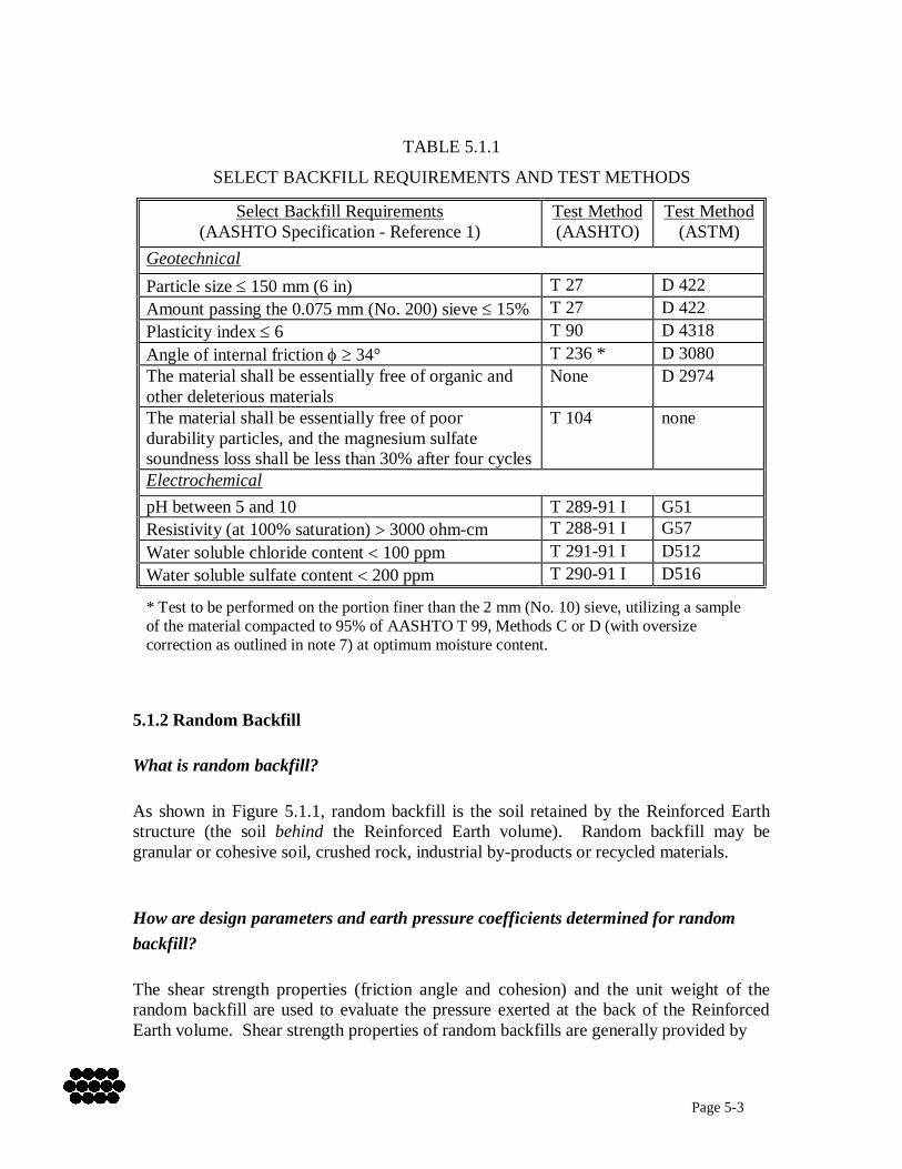
The material must not be aggressive to galvanized steel. What are the minimum physico-chemical requirements for select backfill? Based on statistical analysis of projects throughout the world, RECo has found that approximately 95% of the backfill materials that meet the physical requirements for Reinforced Earth structures also meet the Reinforced Earth electrochemical requirements. The electrochemical properties of industrial by-product backfills must be carefully evaluated in every instance, however, since the properties of these materials depend on details of the manufacturing process and may vary significantly from material to material and from region to region. In general, select backfill materials should meet the requirements and conform to the specifications shown in Table 5.1.1. In very special circumstances, exceptions may be made to these requirements after careful review by a RECo engineer. How does the behavior of a Reinforced Earth structure change if the amount of fines in the select backfill increases? Although the standard specification for Reinforced Earth select backfill requires less than or equal to 15% passing the 0.075 mm (No. 200) sieve, materials with up to 40% passing may be considered under limited circumstances and after careful testing. The Owner/ Consultant must weigh the potential cost advantage of using such fine-grained backfill against the possibly significant increase in the number and length of steel reinforcements required, as well as the resulting increase in the Reinforced Earth backfill volume. In order to justify using a soil with greater than 15% fines as select backfill, the designer must evaluate short term stability factors, including saturation/drainage behavior, and develop construction procedures appropriate to that material. Under no circumstances should a backfill with greater than 15% fines be used in a periodically submerged structure (see Section 4.2.3).
Page 5-3
TABLE 5.1.1
SELECT BACKFILL REQUIREMENTS AND TEST METHODS
Select Backfill Requirements (AASHTO Specification - Reference 1)
Test Method (AASHTO)
Test Method (ASTM)
Geotechnical Particle size 150 mm (6 in) T 27 D 422 Amount passing the 0.075 mm (No. 200) sieve 15% T 27 D 422 Plasticity index 6 T 90 D 4318 Angle of internal friction 34° T 236 * D 3080 The material shall be essentially free of organic and other deleterious materials
None D 2974
The material shall be essentially free of poor durability particles, and the magnesium sulfate soundness loss shall be less than 30% after four cycles
T 104
none
Electrochemical pH between 5 and 10 T 289-91 I G51 Resistivity (at 100% saturation) 3000 ohm-cm T 288-91 I G57 Water soluble chloride content 100 ppm T 291-91 I D512 Water soluble sulfate content 200 ppm T 290-91 I D516 * Test to be performed on the portion finer than the 2 mm (No. 10) sieve, utilizing a sample of the material compacted to 95% of AASHTO T 99, Methods C or D (with oversize correction as outlined in note 7) at optimum moisture content.
5.1.2 Random Backfill What is random backfill? As shown in Figure 5.1.1, random backfill is the soil retained by the Reinforced Earth structure (the soil behind the Reinforced Earth volume). Random backfill may be granular or cohesive soil, crushed rock, industrial by-products or recycled materials. How are design parameters and earth pressure coefficients determined for random backfill? The shear strength properties (friction angle and cohesion) and the unit weight of the random backfill are used to evaluate the pressure exerted at the back of the Reinforced Earth volume. Shear strength properties of random backfills are generally provided by
Page 5-4
the project Geotechnical Consultant based on familiarity with local geology and similar materials. When these parameters must be developed in the laboratory, tests such as the direct shear test (ASTM D 3080) and/or the unconsolidated undrained triaxial test with pore pressure measurements (ASTM D 4767) are conducted as part of the project geotechnical exploration. How are strength parameters determined if the random backfill is a stiff cohesive soil? Finite element studies and measurements on full-scale Reinforced Earth structures have shown that the pressure exerted at the back of the structure corresponds closely to the active state. Therefore the pressure at the back of the structure can be calculated based on the coefficient of active earth pressure, Ka, the unit weight of the random backfill, and the magnitude of any surcharge loads. In the case of Reinforced Earth structures constructed against steep cuts into very cohesive soils, the long term shear strength properties of those soils should be used to evaluate the earth pressure forces. Although the short term strength of a stiff cohesive soil is usually high enough that the material can stand by itself during construction, design parameters which consider the geologic origin of such materials will provide a better indication of the earth pressure expected during the life of the structure.
5.1.3 Random Backfill Placed Against a Cut Slope When the random backfill wedge is very narrow near the lower portion of the Reinforced Earth volume, it may be more cost-effective to place select backfill beyond the end of the reinforcing strips and all the way back to the face of the excavated slope, rather than trying to place and compact random backfill in this narrow area. Placement of the two backfill types in their respective zones may commence once the structure is high enough, and the random backfill wedge wide enough, to permit economical placement operations for each material. Many contractors recognize the increased cost of placing and compacting a narrow wedge of random backfill, viewing the easier placement of select backfill as an economical trade-off against the select material's higher cost. This practice is typically at the contractor's discretion, but the Owner or engineer is also free to specify this backfilling method, in which case the additional select backfill should be included in the bid quantity.
Page 5-5
5.2 Reinforcing Steel What type of reinforcement is used in the Reinforced Earth volume? What is meant by the term "inextensible"? Reinforced Earth walls use inextensible steel reinforcements in the reinforced volume. The term "inextensible" refers to a type of MSE reinforcement, typically galvanized steel, which deforms much less readily than the backfill that envelops the reinforcement. RECo currently uses two main reinforcement types:
Strips - 50 mm wide high adherence (HA) ribbed strips (Figure 5.2.1) and Ladders - 100 mm wide HA ladders (Figure 5.2.2), and 180 mm wide ladders
(Figure 5.2.3). These reinforcements vary in their tensile capacity and pullout capacity. The following subsections discuss the characteristics of the steel reinforcing systems used in Reinforced Earth walls.
5.2.1 Tensile Capacity What is the capacity of the reinforcement? Ribbed reinforcing strips are hot rolled from bars to the required shape and dimensions. The steel used in the reinforcing strips conforms to ASTM A-572 Grade 65 (AASHTO M-223). Allowable tensile capacity of the ribbed strips can be determined in a variety of ways depending upon whether AASHTO (Reference 2), individual State Department of Transportation or other codes are followed. The allowable capacity is typically based on the gross area of the ribbed strip, the specified factor of safety, and the net area of the strip after reduction for corrosion losses. Reinforcing ladders (both HA ladders and wide ladders) are manufactured from cold drawn steel wire conforming to ASTM A-82 Grade 65 and welded in accordance with ASTM A-185. Allowable tensile capacity for ladders is determined in the same manner as for ribbed reinforcing strips, i.e., calculations are made by evaluating the stress in the longitudinal wires after reducing the cross section to account for corrosion losses.
Page 5-6
5.2.2 Pullout Capacity Pullout capacity (Reference 3) depends on the frictional interaction between the reinforcements and the backfill within the reinforced volume. It is calculated as follows: P = f*zAs where P = pullout capacity f* = friction factor = backfill density z = depth of reinforcement As = cross-sectional area of reinforcement (net, after accounting for corrosion loss) Values for f* vary depending on the type of backfill used in the reinforced volume, as discussed in Section 5.1. For ribbed strips and HA ladders, friction factor values are based upon extensive laboratory pullout testing conducted by RECo. HA ladders exhibit pullout behavior similar to that of ribbed strips because the ladder's cross bars are closely and uniformly spaced (every 150 mm (6 in)). By comparison, cross bar spacing on wide ladders varies from 150 to 600 mm (6 to 24 in), making wide ladders behave as wire mat reinforcement rather than as strip reinforcement.
5.2.3 Durability How durable are the reinforcements? The durability of galvanized steel earth reinforcements depends on the electrochemical properties of both the reinforcements and the reinforced backfill. Corrosion of galvanized steel has been studied extensively for more than 60 years in a variety of environments, yielding a large body of data from which have been developed conservative metal loss rates used for design of Reinforced Earth walls (Reference 4). Galvanization is a sacrificial coating of zinc, actively protecting the underlying steel as it (the zinc) is consumed, then providing residual passive protection due to corrosion byproducts left on the steel and in the immediately surrounding soil. We know the rate at which the galvanization is consumed and the rate at which the underlying steel corrodes once the zinc is gone, so it is a simple calculation to determine a structure's expected life. Conversely, given a service life requirement (typically 75 years for permanent structures, 100 years for critical structures, see Section 4.1.3), the amount of steel required to achieve that service life can also be calculated.
Page 5-7
Practically speaking, reinforcing strips are manufactured in a single, standard cross section and design requirements are met by varying the number rather than the size of the reinforcements. The design process takes into account the maximum stress each reinforcement can carry given the project's service life requirement and the metal loss rates discussed above. The backfill characteristics that affect the service life of buried galvanized steel are pH, soil resistivity at 100% saturation, and the levels of dissolved sulfate and chloride ions. Submergence in fresh or salt water increases the potential for corrosion loss, but submerged behavior is well understood and design adjustments can be made to produce safe and durable structures. For normal dry-land construction, the acceptable ranges for pH, resistivity, chlorides and sulfates are (repeated here from Table 5.1.1):
pH 5 - 10 Resistivity 3000 ohm-cm Chlorides 100 ppm Sulfates 200 ppm.
Temporary Reinforced Earth walls generally consist of wire facing and black (ungalvanized) steel reinforcements. Corrosion service life calculations, when required for temporary structures, are performed on a case-specific basis. Corrosion-resistant coatings other than galvanization may be considered, particularly for use in aggressive backfills and marine environments where galvanized steel may not be the best choice. Resin-bonded epoxy is one such material, applied to a minimum thickness of 0.4 mm (16 mils) in accordance with AASHTO M284. This coating is not 100% reliable, however, due to the risk of construction damage when using granular (especially coarse) backfills. Even small penetrations of an epoxy coating in widely spaced areas of the reinforcement can create a problem, since corrosion tends to concentrate more aggressively at these locations where moisture and oxygen can get to the underlying metal, with the corrosion spreading undetected beneath the coating. A new coating developed by RECo under the name "Dunois" combines zinc and aluminum and offers superior durability in aggressive backfill and marine environments. The Dunois coating has undergone 20 years of testing by RECo and is currently being used in demonstration projects in the United States. Dunois is a thermal sprayed coating which, when applied, forms a microscopic matrix of aluminum in which the spaces within the matrix are filled with zinc. The matrix structure provides superior resistance to construction damage. Test results show that this interlocked zinc/aluminum coating does not appreciably deplete over time, providing a protective coating in almost all wall environments with the exception of those which are highly alkaline (aggressive to aluminum). Thermal sprayed coatings are only economical for strip-type reinforcements, however, since much of the spray is lost while being applied to the wires of HA and wide ladder reinforcements.
Page 5-8
5.3 Facings What types of facings are available for Reinforced Earth walls? Reinforced Earth walls can be constructed with any of three major facing types: precast panels, wire facings and concrete masonry blocks. Since the facing is the only visible feature of a Reinforced Earth wall, selection of the right facing type, including size, shape, color and texture, is an important design decision. Precast concrete panels are the most common facing elements used for permanent structures. They are installed vertically, although a batter of 5°-10° may be permitted in limited and carefully considered situations. The panels may be cast in cruciform (Figure 5.3.1), rectangular (Figure 5.3.2) or square (Figure 5.3.3) shapes to meet project engineering and aesthetic requirements. When up to 1% differential settlement is expected along the length of the wall (Section 7.4), the cruciform panel is the best choice because of its joint design and panel edge lip. Where more than 1% differential settlement must be accommodated, vertical slip joints are provided, typically located every 10 to 20 panels along the wall length (Section 9.1). Block facing (Figure 5.3.4) may be appropriate in certain permanent wall applications, especially where batter of as much as 15° is required. However, blocks have a smaller unit area and require more effort not only to construct, but also to align and keep aligned during construction (as compared to the significantly larger precast panels). In addition, block facings do not have open joints between blocks, resulting in direct block-to-block contact and, therefore, virtually no tolerance for differential settlement. Block facings should not be used where differential settlement is expected. For temporary walls, significant economy may be realized through the use of flexible wire facing (Figure 5.3.5). The flexibility of the wire mesh allows the facing to deform and effectively accommodate large settlements. In addition, the wire facing may be converted to a permanent facing after primary settlement and deflections have occurred, either by using cast-in-place concrete or by attaching precast concrete panels. Although less economical than a Reinforced Earth wall built only using precast panels, the temporary-to-permanent wire face system may be justified where significant total and differential settlement is anticipated.
Page 5-9
5.4 Connections How are the Reinforced Earth wall facings attached to the reinforcing strips in the reinforced volume? Each facing type uses a different method for attaching the reinforcements. Precast panels have a tie strip cast into the back face and use a single A325 bolt acting in double shear. The reinforcing strip or HA ladder is held between the top and bottom plates of the tie strip (Figures 5.4.1, 5.4.2), and the connection is made with the bolt. In the case of block facing, vertical holes are formed in the top and bottom of each block during precasting operations. Galvanized steel pins are inserted in the holes and the end loops of a wide ladder reinforcement are placed over the pins to make a positive connection (Figure 5.4.3). Wire facings use either a handlebar connector (Figure 5.4.4) to accommodate regular ladder reinforcements, or a hairpin connector (slotted version, Figure 5.4.5) for HA ladder or ribbed strip reinforcements. The handlebar is woven through the wire facing during construction and the two free ends engage the loops of the regular ladder just as the galvanized pins do in the block facing discussed above. The hairpin (with a slot, as shown in Figure 5.4.5), wraps around the double horizontal wire of the wire facing panel and connects to the ribbed strip or HA ladder by a bolt inserted through holes in the hairpin. The slotted version of the hairpin also allows an additional connection from the front face of the wire-facing panel for attaching a precast panel (Figure 5.4.6). The space between panels is generally filled with open-graded 20 - 25 mm (¾ - 1 in) aggregate. This slot may also serve as the anchorage point for conventional reinforcing bars in a cast-in-place concrete facing (Section 5.3).
5.5 Bearing Pads How is spalling or damage to the concrete prevented at joints between precast concrete panels? Early Reinforced Earth construction utilized strips of resin-bonded cork to provide a horizontal bearing cushion between the top of one panel and the bottom of the panel above. This material proved to be subject to undesirable compression, however, occasionally allowing closure of the horizontal joints between panels. Although this
Page 5-10
behavior was generally limited to very high or heavily loaded structures, significant settlement of the backfill sometimes resulted in the same joint closure. It was therefore necessary to select an alternative pad material. The new pad is fabricated from an EPDM rubber that is highly resistant to ozone oxidation. Most important, it retains its resiliency and does not crack. The pad design consists of a 10 mm thick solid layer topped by four 10 mm high ribs, for a total height of 20 mm (3/4 in), Figure 5.5.1 (there is also a 25 mm (1 in) thick pad used in walls over 6 m (20 ft) high). This design demonstrates a two-phase stress-strain behavior. Low loading produces a relatively large value of strain, corresponding in the field to a flattening of the ribs. As the load increases, corresponding to an increasing height of panels above the bearing pad elevation, the strain rate diminishes as the bearing load is distributed into the full thickness of the pad. Testing indicates only 10 to 15% thickness loss for pads at the bottom of a wall 10.5 m (34.5 ft) high. This pad provides the needed balance between compressibility under increased load and the ability to maintain the panel joint in an open condition. For the few higher walls or higher load-to-compression needs, the 25 mm (1 in) thick pad may be used.
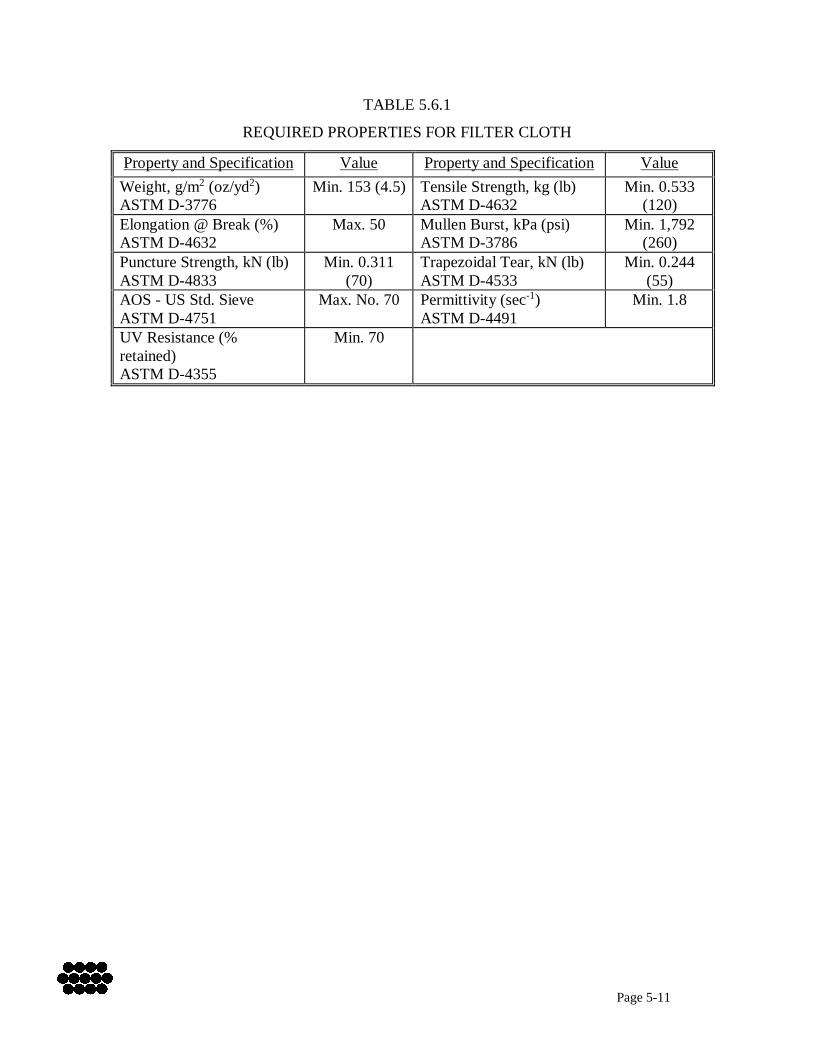
5.6 Filter Cloth How is backfill prevented from flowing through the joints between the facing panels? Reinforced Earth precast panels have shiplap edges and horizontal lips to allow water to drain from the backfill and flow down through the panel joints. Migration of backfill fines into the joints is prevented by 0.5 m (1.5 ft) wide strips of filter cloth glued over the joints on the back face of the wall (Figure 5.6.1). The filter cloth, supplied by RECo, is a non-woven, needlepunched geotextile having the appropriate physical properties to control migration of fines from the types of backfill typically specified for Reinforced Earth structures, while permitting drainage to prevent buildup of hydrostatic pressure. The filter cloth must have the properties shown in Table 5.6.1 (next page).
Page 5-11
TABLE 5.6.1
REQUIRED PROPERTIES FOR FILTER CLOTH
Property and Specification Value Property and Specification Value Weight, g/m2 (oz/yd2) ASTM D-3776
Min. 153 (4.5) Tensile Strength, kg (lb) ASTM D-4632
Min. 0.533 (120)
Elongation @ Break (%) ASTM D-4632
Max. 50 Mullen Burst, kPa (psi) ASTM D-3786
Min. 1,792 (260)
Puncture Strength, kN (lb) ASTM D-4833
Min. 0.311 (70)
Trapezoidal Tear, kN (lb) ASTM D-4533
Min. 0.244 (55)
AOS - US Std. Sieve ASTM D-4751
Max. No. 70 Permittivity (sec-1) ASTM D-4491
Min. 1.8
UV Resistance (% retained) ASTM D-4355
Min. 70
Page 5-12
REFERENCES 1. Standard Specifications for Highway Bridges, American Association of State
Highway and Transportation Officials, 1996 (Sixteenth Edition), 1998 Interim, Division II - Construction, Section 7.3.6.3.
2. Standard Specifications for Highway Bridges, American Association of State
Highway and Transportation Officials, 1996 (Sixteenth Edition), 1998 Interim, Division I – Design, Section 10.32.
3. Standard Specifications for Highway Bridges, American Association of State
Highway and Transportation Officials, 1996 (Sixteenth Edition), 1998 Interim, Division I - Design, Section 5.8.5.
4. Standard Specifications for Highway Bridges, American Association of State
Highway and Transportation Officials 1996 (Sixteenth Edition), 1998 Interim, Division I – Design, Section 5.8.6.1.1.
Page 6-1
6.0 STABILITY Stability of Reinforced Earth structures is dependent upon many factors. The number and length of the reinforcing strips is determined by considering the combined effects of the select and random backfills, the foundation and backslope materials, surcharge loads, service life requirements and, if applicable, submergence conditions and seismic acceleration. Construction methods must also be considered, along with both site and subsoil drainage and scour protection. Ultimately, stability is assured by providing a reinforced granular mass of sufficient dimensions and structural capacity, bearing on adequate foundation material, having a durable facing material, well-chosen drainage systems, and proper embedment of the toe of the wall. Reinforced Earth structures are evaluated for external stability and internal stability. External stability considers the behavior of the site under the loading imposed by the Reinforced Earth structure, and is primarily influenced by site geotechnical and hydraulic conditions. Internal stability refers to the behavior of and interrelationship among the components of the Reinforced Earth structure itself - the facing, the reinforcing strips and the select backfill. Each type of stability will be discussed separately.
6.1 External Stability A Reinforced Earth wall is a flexible gravity structure that resists sliding and overturning due to its mass. The sliding and overturning calculations also consider the effect of hydrostatic and seismic forces that are anticipated to be applied during the life of the structure. Reinforced Earth walls are generally embedded a minimum depth below finished grade, with the depth depending on the wall height and the slope of the finished grade in front of the wall. Actual embedment may exceed the minimum due to grade variations along the wall face.
6.1.1 Sliding and Overturning What are the assumptions used in the sliding and overturning calculations? Although a Reinforced Earth structure is actually a flexible mass, the sliding and overturning calculations assume it behaves as a rigid body (Reference 1). This is a reasonable assumption in the typical design case where the reinforcement length equals or exceeds approximately 70 percent of the wall height. The horizontal forces and moments due to both the random backfill (behind the reinforced volume) and the surcharge loads (above it) are calculated based on the active earth pressure coefficient, Ka, of the random backfill, while passive pressure exerted by the soil in front of the wall
Page 6-2
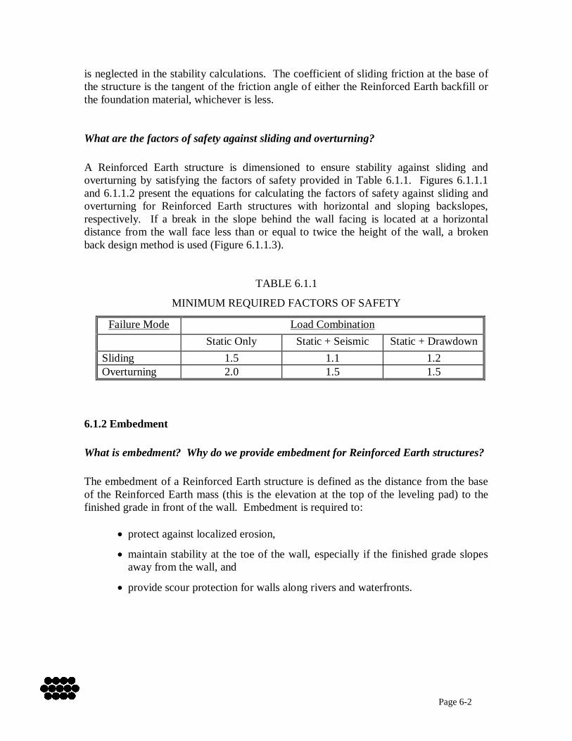
is neglected in the stability calculations. The coefficient of sliding friction at the base of the structure is the tangent of the friction angle of either the Reinforced Earth backfill or the foundation material, whichever is less. What are the factors of safety against sliding and overturning? A Reinforced Earth structure is dimensioned to ensure stability against sliding and overturning by satisfying the factors of safety provided in Table 6.1.1. Figures 6.1.1.1 and 6.1.1.2 present the equations for calculating the factors of safety against sliding and overturning for Reinforced Earth structures with horizontal and sloping backslopes, respectively. If a break in the slope behind the wall facing is located at a horizontal distance from the wall face less than or equal to twice the height of the wall, a broken back design method is used (Figure 6.1.1.3).
TABLE 6.1.1
MINIMUM REQUIRED FACTORS OF SAFETY
Failure Mode Load Combination Static Only Static + Seismic Static + Drawdown
Sliding 1.5 1.1 1.2 Overturning 2.0 1.5 1.5
6.1.2 Embedment What is embedment? Why do we provide embedment for Reinforced Earth structures? The embedment of a Reinforced Earth structure is defined as the distance from the base of the Reinforced Earth mass (this is the elevation at the top of the leveling pad) to the finished grade in front of the wall. Embedment is required to:
protect against localized erosion,
maintain stability at the toe of the wall, especially if the finished grade slopes away from the wall, and
provide scour protection for walls along rivers and waterfronts.
Page 6-3
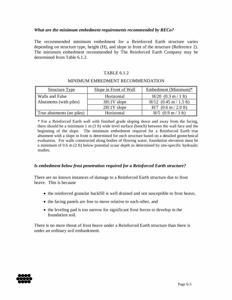
What are the minimum embedment requirements recommended by RECo? The recommended minimum embedment for a Reinforced Earth structure varies depending on structure type, height (H), and slope in front of the structure (Reference 2). The minimum embedment recommended by The Reinforced Earth Company may be determined from Table 6.1.2.
TABLE 6.1.2
MINIMUM EMBEDMENT RECOMMENDATION
Structure Type Slope in Front of Wall Embedment (Minimum)* Walls and False Horizontal H/20 (0.3 m / 1 ft) Abutments (with piles) 3H:1V slope H/12 (0.45 m / 1.5 ft) 2H:1V slope H/7 (0.6 m / 2.0 ft) True abutments (no piles) Horizontal H/5 (0.9 m / 3 ft)
* For a Reinforced Earth wall with finished grade sloping down and away from the facing, there should be a minimum 1 m (3 ft) wide level surface (bench) between the wall face and the beginning of the slope. The minimum embedment required for a Reinforced Earth true abutment with a slope in front is determined for each structure based on a detailed geotechnical evaluation. For walls constructed along bodies of flowing water, foundation elevation must be a minimum of 0.6 m (2 ft) below potential scour depth as determined by site-specific hydraulic studies.
Is embedment below frost penetration required for a Reinforced Earth structure? There are no known instances of damage to a Reinforced Earth structure due to frost heave. This is because
the reinforced granular backfill is well drained and not susceptible to frost heave,
the facing panels are free to move relative to each other, and
the leveling pad is too narrow for significant frost forces to develop in the foundation soil.
There is no more threat of frost heave under a Reinforced Earth structure than there is under an ordinary soil embankment.
Page 6-4
6.2 Internal Stability Internal stability design of a Reinforced Earth structure consists of the determination of soil reinforcement type, size and quantity. Reinforced Earth structures are typically designed utilizing standard reinforcing strips attached to precast concrete facing panels with tie strip connections. Thus, the essence of the internal stability design process is the determination of the required number (density) and lengths of the reinforcing strips. In special cases, alternative soil reinforcement types may be used (see Section 5.2.3). In such situations, the type of soil reinforcement must be selected based on project-specific considerations, but the general procedure for internal stability design remains the same.
6.2.1 Reinforcement Type What is the material and shape of the HA reinforcing strips and HA ladders? Standard Reinforced Earth high adherence reinforcing strips are fabricated of hot rolled steel conforming to the physical and mechanical properties of ASTM A-572 Grade 65 or equivalent. The HA strips are 50 mm wide by 4 mm thick, with 3 mm high ribs oriented perpendicular to the long axis and arranged in pairs on both the top and bottom of the strip, as shown in Figure 6.2.1.1. After fabrication, the reinforcing strips are hot dip galvanized in accordance with ASTM A-123, which provides a minimum of 0.61 kg/sq m (2.0 oz/sq ft) of zinc (0.86 m minimum thickness layer). HA ladders are fabricated from cold drawn steel wire conforming to ASTM A-82 Grade 65. The ladders consist of two longitudinal bars spaced 50 mm (2 in) on center with 100 mm (4 in) long transverse bars spaced 150 mm (6 in) on center. The transverse bars are welded in accordance with ASTM A-185. Like the HA strips, the HA ladders are hot dip galvanized according to ASTM A-123 (0.61 kg/sq m [2.0 oz/sq ft] of zinc). How do the ribs on the HA reinforcing strip (cross bars on the HA ladder) enhance the soil-reinforcement interaction? The high adherence reinforcing strip (ladder) is an efficient soil load transfer device because the soil particles are compacted between and against the faces of the ribs (transverse bars). Horizontal soil stresses are transferred to the steel by direct bearing of soil against the rib (bar) faces, and movement of the strip (ladder) is resisted by soil-to-soil friction across the tops of the ribs (between and across the bars), rather than simply by soil-to-steel friction along the surfaces of the strip (ladder). In addition, soil dilatancy
Page 6-5
leads to apparent friction, f*, that is greater than the soil shear strength (f* > tan ). The importance of the ribs (bars) can be seen by comparing the two coefficients of friction for a typical Reinforced Earth backfill having an internal friction angle = 34:
For plane friction based only on soil shear strength, f* = tan = 0.675.
For HA strips (HA ladders), f* = 2.0 at the top of the structure, decreasing linearly to tan at a depth of 6.0 m (20 ft) and remaining constant at tan for depths greater than 6.0 m.
This means that, due to dilatancy and f*, more frictional strength is available in the upper part of the structure even though there is less confining pressure. Therefore, it is not necessary to have more reinforcements near the top of the panel to compensate for the lower confining pressure. In addition, since the HA ladder is twice as wide as the HA strip, it offers twice the pullout resistance and is more efficient near the top of the wall where pullout controls the design.
6.2.2 Reinforcement Length What is the length of the reinforcing strips? How is it determined? The first step in determining reinforcement length is to satisfy the requirements for external stability (sliding and overturning, see Section 6.1). In general, the reinforcement length resulting from the external stability analysis will prove to be the minimum reinforcement length for the structure. Satisfying internal stability requirements is the next step. For internal stability, the soil reinforcement length must be sufficient to provide the minimum required factor of safety against pullout. AASHTO (Reference 3) requires that the length of reinforcing strips for Reinforced Earth structures be at least 70 percent of the wall height, with a minimum length of 2.4 m (8 ft). These limits are primarily to ensure a stable ratio of base width to wall height, thereby validating the gravity stability calculation assumptions, and to satisfy constructibility considerations. The ribbed surfaces of the reinforcing strip provide an adherence characteristic greater than that of a smooth strip (as discussed above in Section 6.2.1). Extensive testing of Reinforced Earth high adherence reinforcing strips shows that the adherence can be accurately estimated by the frictional parameter known as the apparent coefficient of friction, f* (Reference 4). The value of f* varies by soil type and overburden pressure, and AASHTO (Reference 5) specifies a maximum f* value of 2.0 at the ground surface, decreasing linearly to tan at a depth of 6 m (20 ft) and remaining constant at tan for
Page 6-6
greater depths. Since high adherence strips exhibit greater apparent friction in well graded soils than in fine sands, the f* value used for design of any project must be derived from the type of backfill material to be used (or specified) for that project. For internal stability design, the number and length of the reinforcements must be sufficient to provide an adequate factor of safety against pullout at every reinforcement level. Testing of Reinforced Earth structures shows that a failure plane develops within the reinforced mass, dividing the mass into an active zone and a resistive zone (Figure 6.2.2.1). The active zone is where earth pressure is mobilized and its force transferred to the reinforcements through friction (significant earth pressure is also applied to the facing panels). The resistive zone is where the soil/strip adherence characteristics are mobilized to resist pullout of the strips. The length of the strip within the resistive zone is called the effective length. Earth pressure on the back of a Reinforced Earth structure (at the back of the reinforced soil mass) is calculated by the Rankine method. The effect of a live load traffic surcharge on the calculation of strip pullout factor of safety is determined as shown in Figure 6.1.1.1, while earth pressure for sloping surcharges is determined as shown in Figures 6.1.1.2 and 6.1.1.3. At each level of soil reinforcement, the vertical stress is determined by evaluating all forces acting at and above that level. The summation of forces is considered to be distributed uniformly over an effective width B = L – 2e, as defined in AASHTO (Reference 6) and shown in Figure 6.2.2.2. The horizontal stress is then determined by multiplying the vertical stress by an earth pressure coefficient, K (Reference 7). The earth pressure coefficient is K = Ko (at-rest pressure) at the top of the structure, decreasing linearly to K = Ka (active pressure) at a depth of 6 m (20 ft). K remains constant and equal to Ka below 6 m (right side of Figure 6.2.2.1). Resistive forces are developed along the effective length of the strip and are calculated as the product of the apparent coefficient of friction, f*, the overburden soil pressure and the surface area of strip in the resistive zone (Reference 5). The factor of safety against strip pullout at each level is calculated by the equation
FSf S A N
S Apulloutv s
h p
*
where f* = apparent coefficient of friction Sv = vertical stress due to overburden soil above strip (unit weight x fill height) As = surface area of a reinforcing strip within the resistive zone N = number of reinforcing strips per tributary wall area Sh = horizontal earth pressure at level Ap = tributary wall area.
Page 6-7
6.2.3 Spacing of Reinforcement How many strips are there in a wall? For internal stability considerations, the cumulative cross sectional area of the steel reinforcing strips must be sufficient to carry the soil loads. After subtracting the thickness of steel which will be sacrificed to corrosion during the life of the structure, the reinforcement cross sectional area remaining at the end of the service life is designed to be greater than that required to carry the allowable tensile stress, 0.55Fy (Reference 8). As discussed in the previous section, the earth pressure on the back of a Reinforced Earth structure is determined by the Rankine method. For the strip stress calculation, the effect of any live load surcharge is determined as shown in Figure 6.1.1.1, while the earth pressure for sloping surcharges is determined in accordance with Figures 6.1.1.2 and 6.1.1.3. The procedure for determining earth pressures at each level of reinforcement within the structure is the same as the procedure outlined for reinforcing strip pullout safety in Section 6.2.2, except that the live load surcharge is applied directly over the reinforced zone. This results in higher vertical and horizontal stresses within the Reinforced Earth structure and, therefore, higher stresses in the reinforcement. The result is a more conservative reinforcement design. How is the number of strips per panel determined? Once the horizontal stress transfer at a reinforcement level is determined, the number of strips required at that level is calculated by the following equation:
NS A
A Fh p
s y
( )
( . )0 55
where N = number of strips per tributary wall area (rounded up to the nearest integer) Sh = horizontal earth pressure at that level Ap = tributary wall area As = cross sectional area of reinforcing strip (at end of service life) Fy = yield strength of steel reinforcing strips. The tributary wall area used in the calculation above is typically 2.25 sq m (24.2 sq ft) for Reinforced Earth structures using standard cruciform panels. This corresponds to half a panel high (0.75 m [2.46 ft]), by two panels wide (3.0 m [9.84 ft]). The number of strips
Page 6-8
required per tributary area is then provided across that panel area. Thus, as shown in Figure 6.2.3.1, a required number of strips N = 5 results in panels A5 and B2 across the bottom of a Reinforced Earth structure. The three bottom-most reinforcing strips of the A5, along with the two reinforcing strips of the B2, total 5 strips for the 2.25 sq m tributary area (the shaded area in Figure 6.2.3.1). For other panel types, the number of strips provided per panel is determined as the ratio of the actual panel area to the 2.25 sq m tributary area. First consideration is always given to the use of standard precast facing panels and the efficient use of steel strips when designing a Reinforced Earth structure. The selection of tributary wall area to be used for design and the determination of the distribution of strips attached to the panels maximizes the efficiency of the system. The Reinforced Earth design methodology provides for the uniform distribution of soil reinforcements throughout the reinforced mass, the optimal use of steel reinforcing strips, and the use of standard facing panels.
6.3 Overall (Global) Stability What is the difference between external stability and overall stability? What is the definition of "slope stability" with respect to overall stability of a Reinforced Earth structure? As was discussed previously (Section 6.1), consideration of the external stability of a Reinforced Earth structure is really consideration of the interaction between the Reinforced Earth volume and the foundation soils and random backfill. Specifically, the external stability calculations determine the factors of safety for sliding and overturning (Figure 6.3.1, parts [a] and [b], respectively). A check of overall stability, on the other hand, looks not only at the Reinforced Earth volume and its relationship to the adjacent soils, but also at the characteristics of the deeper strata that will affect the stability of the whole structure, embankment and/or hillside (Figure 6.3.1, part [c]). Depending on the specific site conditions, a global failure plane or slip circle might pass completely outside of the reinforced zone. Since it is easy to provide sufficient reinforcing strips to prevent mobilization of a failure plane or slip circle that does pass through the reinforced soil mass, the presence of the Reinforced Earth structure may actually improve global stability of the entire embankment (Figure 6.3.2). What is the definition of "Factor of Safety" with respect to a global stability analysis? In a stable slope, only a portion of the total available resistance along a potential shear (slip) surface will be required to balance the driving force. Therefore, the factor of safety against shear failure is simply the ratio.
Page 6-9
Force Driving
ResistanceShear AvailableFS
In designing for global stability, it is customary to have a predetermined acceptance value for the factor of safety and to adjust the design until the factor of safety calculated for the design equals or exceeds the predetermined value. A value of 1.3 is customary for most applications, but a value of 1.5 may be required for applications such as bridge abutments or structures supporting railways (critical structures). What are the methods to determine the Factor of Safety against a global failure? Bishop's Modified Method of Slices is the most widely used method for determining the global factor of safety along a potential slip circle. In special cases, such as when there is an inclined fault layer or a weak zone beneath the Reinforced Earth volume, a non-circular analysis may be required to investigate other possible failure modes. RECo uses a modified version of the computer program STABL to perform global stability analysis. Using this program, a non-circular analysis can be performed and stability resulting from the tensile and adherence properties of the reinforcements can be taken into account.
Page 6-10
REFERENCES 1. Standard Specifications for Highway Bridges, American Association of State
Highway and Transportation Officials, 1996 (Sixteenth Edition), 1998 Interim, Division I - Design, Section 5.8.2.
2. Technical Bulletin MSE-7, Minimum Embedment Requirements for MSE Structures,
The Reinforced Earth Company, 1995. 3. Standard Specifications for Highway Bridges, American Association of State
Highway and Transportation Officials, 1996 (Sixteenth Edition), 1998 Interim, Division I - Design, Section 5.8.1.
4. Technical Bulletin: MSE-6, Apparent Coefficient of Friction, f*, to be Used in the
Design of Reinforced Earth Structures, The Reinforced Earth Company, 1995 5. Standard Specifications for Highway Bridges, American Association of State
Highway and Transportation Officials, 1996 (Sixteenth Edition), 1998 Interim, Division I - Design, Section 5.8.5 and Figure 5.8.5.2A.
6. Standard Specifications for Highway Bridges, American Association of State
Highway and Transportation Officials, 1996 (Sixteenth Edition), 1998 Interim, Division I - Design, Section 5.8.3.
7. Standard Specifications for Highway Bridges, American Association of State
Highway and Transportation Officials, 1996 (Sixteenth Edition), 1998 Interim, Division I - Design, Section 5.8.4.1 and Figure 5.8.4.1C.
8. Standard Specifications for Highway Bridges, American Association of State
Highway and Transportation Officials, 1996 (Sixteenth Edition), 1998 Interim, Division I - Design, Section 5.8.6.1.
Page 7-1
7.0 FOUNDATION CONSIDERATIONS This section discusses Reinforced Earth structure foundation issues pertaining to bearing capacity, settlement and differential settlement. The bearing capacity of true abutments is discussed in a separate subsection (Section 7.2) to emphasize its importance and the need for project-specific design information on this topic.
7.1 Bearing Capacity of the Foundation Soil What is the difference between applied bearing pressure and allowable bearing pressure? The applied bearing pressure is the pressure exerted on the foundation soil by a structure such as a Reinforced Earth wall. For a typical Reinforced Earth structure not having a sloping surcharge, the applied bearing pressure can be approximated as 135% of the combined dead weight of the reinforced volume and the surcharge (Reference 1). The allowable bearing pressure, on the other hand, is the value obtained by applying a factor of safety to the ultimate bearing capacity of the foundation soil, where the ultimate bearing capacity has been calculated using the Terzaghi bearing capacity equation (Reference 2) or by a similar method. Bearing capacity primarily depends on the shear strength of the foundation soil, the embedment depth of the structure, and the effect of submerged conditions, if present. Designing a Reinforced Earth structure based on a properly determined ultimate bearing capacity, with a factor of safety applied, is the preferred design method to avoid foundation shear failure. How can bearing capacity theories be applied to a Reinforced Earth Structure? Are there differences in the method of application? Bearing capacity theories are best applied to rigid structures. For semi-flexible structures such as those constructed of Reinforced Earth, one must use engineering judgment in interpreting the results of the bearing capacity equation, since the structure's flexibility both permits and justifies a higher allowable bearing pressure than the calculations suggest. Based on the bearing pressure distribution under the reinforced volume, an equivalent footing width can be assigned to the structure. As illustrated in Figure 7.1.1, Meyerhof has shown that this footing width is equal to the reinforcement length minus two times the eccentricity of the structure. For a cohesionless bearing soil, this width is used in the determination of the ultimate bearing capacity using conventional bearing capacity theory. In the case of cohesive bearing soil, the width of the footing plays a lesser role in determining the bearing capacity.
Page 7-2
Due to the uncertainties inherent in any calculation of soil strength (since soil properties can vary significantly even a few meters away from where a sample was taken), the allowable bearing pressure for footings supporting rigid structures is commonly determined by applying a factor of safety of 3.0 to the ultimate bearing capacity. The comparative flexibility of a Reinforced Earth structure, however, justifies the use of a lower factor of safety against bearing failure (Reference 1, Reference 3), as follows:
a factor of safety of 2.0 for projects with detailed geotechnical information, and a factor of safety 2.5 for projects with general geotechnical information.
Can longer reinforcements be used to reduce the bearing pressure? When insufficient bearing capacity is available, Owners and Consultants sometimes ask about using longer reinforcements in an effort to reduce the applied bearing pressure under the structure. Since the bearing pressure calculation depends, in part, on the base width of the structure, they reason that longer reinforcements (a larger base width) will reduce the calculated bearing pressure. The relationship between the Reinforced Earth volume and retained lateral loads, however, results in eccentricity (Figure 7.1.2) that requires the bearing width (introduced in Section 6.2.2) to be calculated as follows: B = L – 2e where B = Equivalent Bearing Width e = Eccentricity (Figure 7.1.1) L = Reinforcement Length H = Wall Height
As the reinforcement length (L) increases, there is a decrease in eccentricity (e), such that bearing pressure width (B) approaches L. The resulting bearing pressure, therefore, cannot be reduced to less than the load of the soil mass, irrespective of the reinforcement length (see figure 7.1.2).
Page 7-3
7.2 True Abutment Bearing Capacity What is a "true abutment?" What is the allowable bearing pressure? A true abutment is a Reinforced Earth structure with a bridge abutment spread footing bearing directly on top of the reinforced soil (Figure 7.2.1). The footing bears only on the reinforced soil and is not supported by piles or other structural members. Abutment bearing pressure is transferred directly into the reinforced soil and, depending on the height of the Reinforced Earth structure, either is fully dissipated within the reinforced soil or is distributed through it to the site foundation soil below. The following must be considered when designing a Reinforced Earth true abutment:
The bearing capacity of the site foundation soil, as discussed in Section 7.1.
The allowable bearing pressure of the beam seat atop the Reinforced Earth select backfill. The allowable bearing pressure is set at 190 kPa (4000 psf), consistent with good engineering practice for footings on compacted granular fill.
The pressure under the abutment footing is dissipated with depth through the Reinforced Earth volume according to the Boussinesq pressure distribution (Reference 2). For computational simplicity, and because it is conservative (it envelopes the Boussinesq distribution), a 1:2 (Horizontal to Vertical) linear pressure distribution is used instead (Figure 7.2.2). In order to limit the pressure applied directly to the wall facing panels, the abutment's centerline of bearing must be at least 1 m (3 ft) behind the facing. Where the 1:2 distribution intersects the face of the Reinforced Earth wall, the load from the abutment is transferred through the reinforcing strips back to the reinforced soil mass as horizontal stress. This increased horizontal stress in a Reinforced Earth true abutment may require additional reinforcing strips as compared to a retaining wall design. What is the affect of the abutment footing on the applied bearing pressure beneath the Reinforced Earth structure? When the Reinforced Earth wall height exceeds three times the width of the abutment footing, the bearing pressure from the abutment is almost completely dissipated within the Reinforced Earth volume according to the 1:2 pressure distribution discussed above. Therefore, the foundation soil does not receive significant additional bearing pressure due to the presence of the abutment. This is an important advantage in the case of marginal foundation soils that can accept the distributed load of a Reinforced Earth wall but not the additional concentrated load of an abutment footing. This bearing pressure advantage offered by a Reinforced Earth abutment may allow the abutment to be built without piles.
Page 7-4
For abutment walls of lesser height (those less than twice as high as the abutment footing is wide), the total bearing pressure at the foundation will be the sum of the undissipated portion of the 1:2 pressure distribution (the portion which extends below the base of the reinforced volume) and the bearing pressure determined by conventional Reinforced Earth design calculations. Therefore, the allowable bearing pressure for the site must be sufficient to support this increased load.
7.3 Total Settlement What is the "total settlement" of a Reinforced Earth structure and what behavior contributes to this settlement? The total settlement of a Reinforced Earth structure is the sum of
the settlement of the foundation soil due to overburden pressure (in this case the Reinforced Earth structure is the overburden), and
the internal compression of the reinforced fill due to the compaction effort used
and the vertical forces applied to the structure. Due to the interaction between the reinforcing strips and the select backfill, the internal behavior of a Reinforced Earth structure is different from that of an unreinforced embankment of the same backfill material. As layer after layer is added to a Reinforced Earth structure, the reinforced volume behaves as a block and the reinforcements prevent post-compaction lateral strain and the resulting shortening of the structure in the vertical direction (internal settlement). Therefore, the internal settlement of a Reinforced Earth structure is limited to the negligible compression of the select backfill. On the other hand, settlement of the foundation (in-situ) soil caused by construction of a Reinforced Earth structure may be estimated using classical soil mechanics theory. Since the settlement of a Reinforced Earth structure during construction is adjusted for incrementally in the wall construction process, the structure's allowable post-construction settlement is typically limited only by the deformability of the facing. In some cases, post-construction settlement may also affect structures adjacent to or supported by the Reinforced Earth mass, such as true bridge abutments or major sign structures. If post-construction settlement is anticipated to exceed 75 mm (3 in), an appropriate waiting period (typically at least 2 months) may be recommended before installing the adjacent or supported structure and before adjusting the final design elevations along the top of the Reinforced Earth facing. Settlement expected to be in excess of 300 mm (12 in) may require a waiting period too long for the project timeline, in which case two-stage construction or foundation stabilization techniques should be investigated.
Page 7-5
What is the tolerable total settlement for a Reinforced Earth structure? There is no formal definition of the tolerable total settlement for a Reinforced Earth structure. Some Reinforced Earth walls have experienced as much as 0.6 m (2 ft) of total settlement. While this might be acceptable for a retaining wall not having a roadway or other elevation-sensitive structure on top, it would be totally unacceptable for an abutment or a wall connecting to another structure (unless the settlement could be compensated for in some manner). In general, settlement is not much of a concern if it is not accompanied by an unacceptable amount of differential settlement (see Section 7.4), since it is excessive differential settlement that can lead to wall damage. What are the effects of "immediate settlement" and "consolidation settlement" on Reinforced Earth structures? Immediate settlement is settlement that occurs (and ends) during or very soon after wall construction, usually within the time during which the overall project is still under construction. This timing often permits the wall components, the project grading, or both to be adjusted to make up for the elevation "lost" due to settlement, allowing the project to be completed to the originally specified grades. If it occurs uniformly under the whole structure and is properly corrected, immediate settlement should have no effect on the long-term behavior or performance of a Reinforced Earth structure. Consolidation settlement, on the other hand, is long-term settlement due to consolidation of the foundation soils under the load imposed by the Reinforced Earth mass (and by other project components). Consolidation settlement can go on for months or even years, but the rate of settlement generally decreases with time. For this reason, a geotechnical report that predicts consolidation settlement should include an estimate of T90, the time for 90% of the expected settlement to occur. The project Owner should understand that, ideally, remedial measures to compensate for this settlement should not be attempted at least until T90 has been reached, although earlier remediation may be acceptable or required depending on project conditions. Note that immediate and consolidation settlement are not necessarily harmful to the structural integrity and performance of a Reinforced Earth wall, as long as they occur evenly under the whole structure. If the magnitude of settlement varies along the length of a wall, however, this differential settlement could, under certain circumstances, pose a problem. This issue is addressed fully in Section 7.4.
Page 7-6
7.4 Differential Settlement What is the definition of "differential" settlement? Differential settlement is the difference between the amounts of settlement observed at two different points on a structure, expressed as a percentage of the distance separating those points (Figure 7.4.1). For example, if they are separated by 100 m and one point settles 1 m more than the other does, then the differential settlement is 1%. Differential settlement is always determined relative to the initial and final positions of the two points, so if one point settles 1 m and the other settles 2 m, the differential settlement is still 1 m (= 1% if they are 100 m apart as in the example above). The two points do not have to be at the same elevation initially in order to calculate differential settlement. What is the tolerable differential settlement for a Reinforced earth structure? The performance of a Reinforced Earth structure during settlement depends primarily on the characteristics of its facing system. A Reinforced Earth wall constructed of precast concrete panels can tolerate up to 1% differential settlement without any distress, so the effect of varying foundation soil properties is rarely a problem (Reference 1). However, if the geotechnical investigation suggests that greater than 1% differential settlement may occur, slip joints (Section 9.1) may be used, typically located every 10-20 panels (15-30 m [50-100 ft]) along the wall. In the case of a very high wall, tiers (Section 9.13) may be used to produce a stack of 2 or more walls, each of lesser height and set back behind the one below, reducing the effect of settlement on each wall as compared to the effect on a single wall of the combined height. What are the causes of differential settlement? There are four principal causes of differential settlement of Reinforced Earth walls:
Significant variation in the strength characteristics of the foundation soils along the
length of the wall, A sudden change in wall height or structure geometry such that there is a sudden
change in the load imposed on the foundation, The presence of a large, rigid structure adjacent to the Reinforced Earth wall, and An acute corner unavoidably located where foundation soils are less competent
(although an acute corner may be lighter than the adjacent "normal" wall, bearing pressure is more concentrated, leading to increased bearing stress). See also Sections 9.3 and 9.13.
Page 7-7
7.5 Foundation Stabilization Methods In marginal soil conditions, how can bearing capacity be improved and how can total and/or differential settlement be minimized? In some cases, the bearing soils located beneath planned Reinforced Earth structures are in such a marginal state that improvement is necessary to provide adequate bearing capacity and/or to reduce both immediate and consolidation settlement (see Sections 7.3 and 7.4 for discussions of settlement). Several foundation soil improvement methods that have been successfully used to increase bearing capacity and reduce large-scale settlements beneath Reinforced Earth structures are discussed below.
Undercut and Replace. The simplest (and most frequently used) method is to undercut the weak soil and replace it with select granular material (Figure 7.5.1). If the required depth of undercut exceeds 2 - 2.5 m (6.5 - 8 ft) or if groundwater is near the surface, however, undercutting may be impractical and/or uneconomical.
Preloading. Traditionally, preloading is the construction of a temporary
embankment for the purpose of forcing both immediate and (at least some) consolidation settlement of the foundation soil prior to erection of the final structure (Figure 7.5.2). Where appropriate, depending on the rate and amount of settlement expected, a particularly time- and cost-efficient version of preloading is erection of the Reinforced Earth structure in stages, allowing it to act as the preload surcharge. This method provides opportunities to modify the structure design if needed as settlement occurs.
A variation of the "build-the-wall-in-stages" technique is the staged construction of
a Terratrel® wire-faced Reinforced Earth structure. Terratrel's wire facing has far more flexibility and differential settlement tolerance than does a precast facing, so the Terratrel wall can accommodate significant post-construction settlement. Precast panels or a cast-in-place facing can be erected after settlement has stopped.
Clearly, a careful geotechnical evaluation should accompany any preloading
scheme to prevent overloading and shearing of the bearing soils. In addition, installation of wick drains during preloading can be considered to further increase the rate of settlement by dissipating pore water within the bearing soils.
Foundation Stabilization. Soil stabilization measures may be used to create a
surface layer of select, reinforced soil below the Reinforced Earth structure. The stabilization layer can be created either (a) by installing over the marginal soils a 1 - 1.5 m (3 – 6.5 ft) thick layer of select granular fill reinforced by several layers of geosynthetic or steel strip reinforcement or (b) by performing in-situ soil cement mixing in the upper 1 - 1.5 m of the marginal soil layer (Figure 7.5.3).
Page 7-8
Controlled Modulus Columns (CMC) or Dynamic Replacement Columns. These technologies are available from Menard LLC, Soil Improvement Specialists, a wholly owned subsidiary of The Reinforced Earth Company. More information on Menard technologies can be obtained through any RECo office.
Column Inclusions. Stone columns, jet grouted columns, vibro-replacement
columns, and other inclusion installations have been used to transfer loads from Reinforced Earth structures through marginal upper soils and into a deeper, more stable soil or bedrock layer. Added benefits of column inclusions may include improvements to base lateral stability and reduced waiting time compared to preloading schemes (Figure 7.5.4).
Project Modifications. Although they are not specifically foundation stabilization
measures, there are certain modifications to the project geometry or to the Reinforced Earth materials that may help provide a stable structure. One such modification is the placement of a berm in front of the Reinforced Earth mass to create a counterweight to resist possible slip surface movement (Figure 7.5.5a). Another is the use of lightweight fill materials, such as natural or processed low density aggregate, to reduce the load transferred from the Reinforced Earth structure to the foundation soil (Figure 7.5.5b).
Page 7-9
REFERENCES 1. Subsurface Investigation and Improvements for MSE Structures Constructed on Poor
Foundation Soils, The Reinforced Earth Company, undated. 2. Soil Mechanics and Engineering Practice, Second Edition, Karl Terzaghi and Ralph
B. Peck, John Wiley & Sons, 1967. 3. Standard Specifications for Highway Bridges, American Association of State
Highway and Transportation Officials, 1996 (Sixteenth Edition), 1998 Interim, Division I - Design, Section 5.8.3.
Page 8-1
8.0 WALL CONSTRUCTION DRAWINGS AND GENERAL DETAILS The Reinforced Earth Company (RECo) provides Owners with two types of drawing sets for approval and use during construction:
Wall Construction Drawings (sometimes called "Shop Drawings") and Panel Casting Drawings.
This section describes the wall construction drawings and identifies the information needed by RECo to produce them. For completeness and clarity, Reinforced Earth drawings typically include RECo notes and details necessary to accurately, completely and clearly show how to construct the Reinforced Earth walls. In order for the wall construction drawings to provide this accuracy, completeness and clarity, it is crucial that the Owner or Consultant provide comparably accurate, complete and clear information in the contract documents or other pre-bid communications. Often the contract documents contain a section devoted exclusively to wall control data; this arrangement makes for efficient communication of the necessary information. The wall construction drawings include a complete elevation view of the wall, as well as one or more cross sections and all necessary details. RECo's wall construction drawings will only include a complete plan view of the wall if one of the following is true:
RECo has had to modify the plan view provided in the contract documents.
The Reinforced Earth volume must be shown in relation to the location of specific loads (such as building foundations).
A wall plan view is required by the Owner’s specifications.
Bid quantities are provided prior to bid. However, wall construction drawings are not provided prior to bid if the Owner's plans include wall location, geometry and dimensions, unless there are unusual or complex issues that must be clarified by RECo or if submission of wall construction drawings is required by the Owner. Since there is a wide range of wall design details, any of which may or may not be used in a particular set of wall construction drawings, these details are itemized and discussed separately in Section 9.0. The Reinforced Earth Company does not prepare rebar bending diagrams or materials lists for cast-in-place concrete structures.
Page 8-2
8.1 General Notes What topics are covered in the General Notes? In addition to the project title, the cover sheet provides general notes covering the following topics:
Assumptions regarding soil materials, construction methods and quality of materials.
Design criteria for soils and supplied materials, including who has responsibility
for determination of allowable bearing pressure, designation of unsuitable foundation materials and methods for handling those foundation materials.
Wall layout information. Construction requirements for backfill compaction and storm water control, and
responsibility for cast-in-place concrete rebar detailing. Conflicting structures within the Reinforced Earth volume, such as manholes,
drainage pipes, piles, guardrail posts, pavements and other structures. Materials supplied by others, backfill quantities, nominal reinforcing strip lengths
and precast panel finishes. In addition, job-specific notes are added as necessary for communication of project requirements.
8.2 Elevation What information should the Owner or Owner’s Consultant provide? The following information is required in order for The Reinforced Earth Company to produce a complete elevation drawing for construction use: A. Wall Control Drawings (Owner's Contract Plans)
Site plan - beginning and ending stations for wall, centerline of roadway, alignment
of front face of wall, offsets to front face of wall, curve data (PT, PC, radius of curvature).
Elevation - top of wall elevations (gutter line, top of barrier or coping), finished
grade elevations in front of wall (not leveling pad elevations - see Section 8.6 for explanation).
Typical section through wall - the typical section permits a more detailed look at
Page 8-3
the system being designed and should clearly indicate the minimum depth (not elevations - see Section 8.6 for explanation) of top of leveling pad below finished grade, the point on the structure where top of wall elevations are given, and the points to which offsets are referenced (e.g., front face of panels or face of barrier or coping).
B. Other Contract Plans - Only required by RECo if this information is not provided in
Wall Control Drawings (see above):
Bridge plans - abutment/wall interface, pile locations/interfering piles, bridge loads. Drainage plans - locations of inlets, outlets, pipes etc. Lighting plans - locations and types of poles to be installed adjacent to the wall or
mounted on the wall barrier. Utility plans - type, size and location of any utilities running under, through or
adjacent to the wall or which are to be mounted on the wall barrier. Sign plans - type, size and location of any signs that may interfere with any part of
the wall, especially the reinforcing strips. Other details - such as coping or barrier mounted on the Reinforced Earth wall.
What is shown on a finished elevation drawing? After receiving the information outlined in the two lists above, The Reinforced Earth Company is able to produce wall elevation drawings. The sample wall elevation drawing in Figure 8.2.1 illustrates what is typically provided:
Contractor's construction lengths and elevations for each section of leveling pad. Precast panel configuration (both standard panels and special cut panels), including
number of tie strips per panel. Top of wall elevations (may be given at gutter, top of barrier or top of coping). Type of structure to be constructed on top of the wall. Location of drainage structures. Length and location of the reinforcing strips (see Section 8.5 for more information
concerning reinforcing strips). Maximum applied bearing pressure under the wall for each reinforcing strip length
(to aid the reviewer of the design calculations). Panel columns numbers - an especially useful tool when discussing the wall over
the telephone or tracking construction progress in the field.
Page 8-4
8.3 Typical Sections What information is presented on the Reinforced Earth wall typical section? It is very helpful to RECo when the Owner or Consultant provides a typical cross section through the wall(s) showing the information listed below. If a cross section is not provided, however, it is essential that the listed information be provided in writing. In general, the Reinforced Earth typical section will include the following information (see Figures 8.3.1 through 8.3.4):
Information Provided Should Be Provided By Location of front face of wall
Owner
Proposed finished grade in front of wall
Owner
Top-of-wall treatment (e.g., unfinished, coping, barrier, abutment, other)
Owner
Reinforcement length
RECo
Leveling pad elevation
RECo
Limits of select backfill (sometimes called "granular material")
RECo
Embedment depth
RECo, unless specified by Owner
Limits of excavation and random
backfill (may or may not be shown, depending on project circumstances/requirements).
Owner
Details to supplement the cross section will be added as needed. Typical details found in wall construction drawings are discussed in Section 9.0.
8.4 Typical Panel and Connection Details What is the configuration of a typical panel? Precast concrete facing panels for Reinforced Earth walls are produced in a variety of sizes and shapes so that some combination of them will conform to nearly any wall configuration or dimensions. With the exception of the special configuration Square or Large Rectangular Panels, Reinforced Earth panels can be recognized by their
Page 8-5
characteristic cruciform shape. The panels have “ears” protruding from each side, so the centerline of the panel joint is the centerline of the overlapping ears of adjacent panels (Figure 8.4.1). This shape allows panels to interlock in the plane of the wall without compromising facing flexibility. How is facing flexibility achieved? Flexibility of the facing is achieved by using relatively small panels having shiplap joints but no other panel-to-panel connections. This flexibility is maintained by specially fabricated elastomeric bearing pads that support the panel above while preventing panel-to-panel contact. There is no other connection between panels. The flexibility of this joint system allows the panels to be adjusted horizontally during installation as well as move vertically in case of settlement (note that walls using larger panels are less flexible and are, therefore, somewhat less tolerant of differential settlement). The dimensional tolerance designed into the joints also permits panel rotation about the joint centerline, allowing a wall to follow a curved alignment made up of a series of short chords of length equal to a panel's nominal width. In addition to creating facing flexibility, the panel joints are an important part of the wall drainage system. To prevent soil particles from clogging them, the joints are protected by strips of filter cloth, 0.45m (18 in) wide, applied as the panels are erected. The filter cloth cannot be seen from the front of the wall due to the shiplap design of the panel joints. Three types of facing panels make up the majority of the panels in any wall - center, bottom and top panels. Each is described below and shown in Figures 8.4.2a and 8.4.2b.
Center Panels The majority of the panels in most walls are center panels, designated type A. An
A panel is 1.5 m (4.92 ft) high and measures 1.5 m wide between the centerlines of the panel ears. A panels generally cover the internal wall area, away from the periphery, and are typically shown as squares on the elevation view in the wall construction drawings.
Bottom Panels A panels can also be bottom panels, in which case type B panels are used at
alternate panel locations along the leveling pad (between the As). The B panel is exactly the top half of an A panel and, because it sits in the same orientation as the A panels, it fills the gaps between them. When dictated by wall height and foundation elevation requirements, panel types P and Q (a P is 1.25 times the height of an A, while a Q is 1.5 times the height of a B) may be used instead - or in combination with - A and B panels. When used in combination with A and B
Page 8-6
panels, P and Q panels also allow the leveling pad to step up or down in increments of 0.375 m (1.23 ft) instead of a half panel step height of 0.75 m (2.46 ft) (Figure 8.4.2). All bottom panels are shown in Figure 8.4.3.
Top Panels Panel types C, D, E, F, G, H, K and L are always used at the top of the wall,
ensuring a horizontal top line where that is required. A stepped wall top can be achieved by the pairing of a C panel with a G panel, a D with an H, an E with a K, and an F with an L, producing a series of 0.187 m (0.615 ft) steps (these steps are especially useful for following a grade beneath a cast-in-place coping or barrier). Panels HN and HM are used when a specific 2:1 slope is required. All top panels are shown in Figure 8.4.3.
The panels described above are those used most frequently. Non-typical panel types, such as corner elements, slip joints and other slope-top panels, are discussed in Section 9. How are reinforcing strips connected to panels? Reinforcing strips are connected to panels using galvanized steel tie strips (Figure 8.4.4.). A tie strip's triangular head and the adjacent portion of its twin connection tabs are cast into the concrete, with the balance of the tabs protruding from the back of the panel. The tabs, separated by just enough space for insertion of a reinforcing strip, have prepunched holes through which the strip is bolted. The number of tie strips cast into a panel is indicated in the panel nomenclature by a numerical suffix to the panel designation (a panel designated "A4 is a type A panel with 4 tie strips). How is a panel reinforced internally? All Reinforced Earth wall panels contain rebar. The quantity of rebar is determined from the reinforcement designation, "Rx," where "x" is the number of vertical bars in the panel. R4 is the minimum configuration (Figure 8.4.5), while R6 reinforcement adds a pair of vertical bars flanking the center tie strips. Reinforcement types R4 and R6 are the most common, with other configurations used for heavier loading conditions. Therefore, a complete panel nomenclature would be A4R4, and this information is shown on the panel casting drawings and used as the piece mark for manufacturing and field identification.
Page 8-7
8.5 Reinforcing Strips Reinforced Earth high adherence (HA) reinforcing strips are fabricated of structural steel conforming to ASTM A572, Grade 65, and are galvanized according to ASTM A123. The cross section is constant at 50 x 4 mm (1.969 x 0.157 in). The strips are called "high adherence" due to the high strip-to-soil shear resistance created by the ribs on the top and bottom surfaces (Figure 8.5.1). The strip lengths vary according to the structure's design. The supplied length is never shorter than the nominal length shown on the drawings, but may exceed it by as much as 0.15m (6 in). Reinforcing strips are attached to the tie strips by ASTM A325 bolts, 12.5 mm diameter by 32 mm long (0.5 in by 1.25 in). For design, the controlling cross section of the strip is the full cross section, not the reduced section at the bolt hole (because the reduced section is protected against corrosion on both the top and bottom by the tie strip). Figure 8.5.2 illustrates the connection of the reinforcing strip to the tie strip.
8.6 Leveling Pad Steps What determines the configuration of the leveling pad? What information is needed to choose the location of the pad steps? The 150 m thick by 300 m wide (6 in by 12 in) unreinforced concrete leveling pad is designed with steps positioned to minimize the amount of wall material below the Owner-specified minimum embedment line (Figure 8.6.1). To give wall designers the flexibility to achieve this goal, The Reinforced Earth Company recommends that the Owner or Consultant not specify leveling pad lengths and elevations but simply define the finished grade in front of the wall and the minimum required embedment depth. RECo engineers can then select the most cost-efficient combination of panels and steps consistent with the Owner's requirements. What is the relationship between the leveling pad step and the panel joint centerline? The leveling pad lengths shown on the elevation drawing are not physical lengths of the leveling pad, but rather nominal distances from the centerline of the panel joint to the end of that particular pad section. The relationship between the actual end of pad and centerline of panel joint is shown on the standard design drawings in the "Typical Leveling Pad Step Detail" (Figure 8.6.2).
Page 9-1
9.0 TYPICAL DESIGN DETAILS The economy, safety and aesthetics of a Reinforced Earth structure can be greatly enhanced by positive and consistent interaction among the Owner, the Consultant and The Reinforced Earth Company. This interaction should start at the earliest stage of the project and continue through the design and construction phases. Such communication not only maximizes the Owner's/Consultant's understanding of the Reinforced Earth system's possibilities and benefits for the project, but it also enables the Reinforced Earth designers to suggest approaches which will enhance the value and functionality of the finished product. Based on the above idea of maximizing understanding of the Reinforced Earth system, this section reviews the various design details that enable a Reinforced Earth structure to best meet the design and functionality needs of a project. Section 9 is broken down into four general categories of details, as follows: System Accessories Related Structures Drainage Details 9.1 Slip Joints 9.7 Traffic Barriers* 9.12 Drainage Details* 9.2 Butt Joints 9.8 Parapets* 9.3 Corner Elements 9.9 Bridge Seats* Geometric Details 9.4 Coping 9.10 Horizontal Inclusions 9.5 Slope-top Panels 9.11 Vertical Inclusions 9.13 Acute Corners 9.6 Connections 9.14 Curves 9.15 Tiered Walls *These structures and details are designed by the Owner or Owner's Consultant. They are shown on RECo's drawings for completeness. System Accessories
9.1 Slip Joints What are slip joints? Where are they used? Slip joints are continuous vertical joints provided at selected locations along a Reinforced Earth structure. A slip joint replaces the normal vertical joint system, substituting a vertical separation between adjacent panels that extends the full height of the wall. The sections of wall on either side of the slip joint are, therefore, able to behave independently of each other. The slip joint design uses either an exposed slip joint panel having its own reinforcing strips (Figure 9.1.1) or a hidden "backup" panel in the backfill behind the facing panels (Figure 9.1.2). Both panel types prevent loss of backfill through the joint.
Page 9-2
There are four primary reasons to use slip joints:
To provide additional facing flexibility for severe differential settlement due to foundation conditions. Normal facing flexibility can accommodate up to 1% differential settlement (1 m settlement along 100 m of wall length), while properly spaced slip joints can significantly increase a Reinforced Earth wall's differential settlement tolerance (Figure 9.1.3). See Section 7.4 for a more detailed discussion of differential settlement.
To address the special case of differential settlement where wall foundation
conditions change abruptly (Figure 9.1.4), or when a Reinforced Earth bridge wingwall "steps off" the rigid concrete foundation of the heel of the abutment onto the relatively more flexible soil foundation beyond the heel. A slip joint at this transition prevents unsightly and potentially damaging facing distress.
To cover and add flexibility to the transition from a Reinforced Earth structure to a
cast-in-place concrete structure, as when a retaining wall abuts the headwall of a culvert (Figure 9.1.5) or the concrete wingwall of a bridge.
To accommodate a curve having a radius less than 7.5 m (25 ft) (Figure 9.1.6).
Although not necessarily a situation requiring additional facing flexibility as in the three situations discussed above, slip joints are used in a small radius curve to prevent the "ears" of the cruciform panels from interfering with each other (see Section 8.4). Curving the wall to a small radius requires more joint rotation than is permitted by the clearance between the concrete surfaces of the adjacent panel ears. See Section 9.14 for further discussion of curved Reinforced Earth walls.
9.2 Butt Joints What are Butt Joints? Where are they used? A butt joint is a vertical break in the wall face where a wall abruptly changes direction (a corner or angle), or where a wall ends adjacent to another structure. Butt joints resulting from direction change are not covered (whereas most slip joints are covered - see Section 9.1). Butt joints generally consist of a 20 mm (3/4 in) open joint between two columns of precast panels, or between the precast panels and the adjacent structure. Geotextile fabric is adhered to the fill side of the joint to prevent loss of backfill. While butt joints are typically used for changes in wall alignment in excess of 180, they may also be used for 90 bends on low walls where aesthetics is not a concern. Several typical butt joint configurations are described below.
Wall with a 270 bend (Figure 9.2.1). Note that this configuration allows the use of standard cruciform panels in one column and panels cut to fit a vertical plane in the
Page 9-3
adjacent column, reducing the number of special panel types and simplifying the wall erection process.
Wall with an obtuse bend (Figure 9.2.2). This configuration also allows for the use
of one column of standard panels and one column of cut panels, but the cut panels for an obtuse bend must be mitered to ensure proper wall alignment.
Wall with a 90 butt joint (Figure 9.2.3). This detail works well for low walls, but
requires that panels on both sides of the joint be cut panels. When aesthetics counts, a corner element (see section 9.15) gives a more finished look. A 90 butt joint may also be used for medium height walls, but certain modifications to the detail are required and must be determined on a job-specific basis.
At the interface between a Reinforced Earth wall and a cast-in-place structure
(Figure 9.2.4). Note the 100 x 100 mm (4 x 4 in) cast-in-place lip in front of the precast panel or the 100 x 150 mm (4 x 6 in) notch in the cast-in-place structure to receive the Reinforced Earth panels. The lip or notch hides or masks any movement of the more flexible Reinforced Earth structure relative to the rigid cast-in-place structure. It also hides or minimizes the visibility of the premolded joint filler between the cast-in-place and Reinforced Earth structures.
At the interface between a Reinforced Earth wall and an existing structure (Figure
9.2.5), where no lip is available (as described immediately above) and where the front face alignments must be offset, preventing use of a slip joint panel (see Section 9.1).
9.3 Corner Elements What are corner elements and where are they used? Corner elements are specialized facing panels that change the wall alignment at a particular point (Figure 9.3.1). Their shape is similar to that of slip joints (see Section 9.1) except they are folded about their vertical centerlines. The adjacent regular facing panels are cut off vertically, just like the panels flanking a regular slip joint. Angles less than 162 are handled well by corner elements, while angles between 162 and 180 are best handled as curves (see Section 9.14). Full size corner elements are the same height as regular facing panels and have two tie strips at elevations matching those on the regular panels. Therefore, corner elements are held in place by their own reinforcing strips. Any corner element turning an angle of less than 90° is, by geometric definition, acute (Figure 9.3.1). Since some acute corners require special design treatment, depending on
Page 9-4
the relationship between the angle turned and the height of the wall, the reader is referred to Section 9.13, Acute Corners, to determine if this special design treatment is required on a particular project. Although almost any angle can be achieved using a butt joint (Figures 9.2.1, 9.2.2 and 9.2.3), a more finished appearance results from using a corner element as shown in Figures 9.3.1, 9.3.2, and 9.3.3.
9.4 Coping What is a coping and what is its purpose? A coping is a cast-in-place or precast architectural treatment that creates smooth, clean lines at the top of a Reinforced Earth wall (Figure 9.4.1). Whether the top panels all end at the same elevation or they step to follow a sloping grade, the coping overhangs the front of the wall by a minimum of 50 mm (2 in), hiding any panel-to-panel elevation changes (Figure 9.4.2). As shown in Figure 9.4.3, cast-in-place coping may be placed vertically to finish off panel edges around a bridge abutment seat (also see Section 9.9). In section, the precast coping unit is an inverted letter U (Figure 9.4.5), with lifting anchors for placement (Figure 9.4.6). Precast coping units are typically cast in 3.0 m (10 ft nominal, 9.84 ft actual) sections having square ends (Figure 9.4.4). The 3.0 m length exactly matches the spacing of every second vertical joint along the top of the wall. Before installing precast coping, the top of the wall must be smooth and free of steps or irregularities. To accomplish this, level-up concrete fill is cast on top of the panels. The smooth finished grade of this concrete fill must follow a line 0.23 m (9 in) below the top of coping elevation. Top panels that are to receive precast coping are manufactured with dowels protruding from their tops to tie in the level-up concrete (these dowels may have to be field-cut to fit). Once the level-up concrete is set, the precast coping units are placed on the top of wall, separated by the 13 mm (0.5 in) open joints discussed above. When is cast-in-place coping recommended in place of precast coping? Cast in place coping is recommended in situations where the wall follows a significant horizontal or vertical curve. Since precast coping sections are cast with square ends, joints between coping sections (as seen from the front of the wall) may become too tight or too wide, depending on whether the radius point is in front or behind the wall face, respectively. Cast-in-place coping should be used at slip joints so the in-place characteristics and measurements of the slip joint can be accommodated (Figure 9.4.7). Refer to Figures 9.4.1 and 9.4.2 for cast-in-place coping details. Cast-in-place coping should also be used where a wall has a horizontal or vertical bend.
Page 9-5
Figure 9.4.8 shows cast-in-place coping that supports fence posts, while Figure 9.4.9 shows how coping works with a drainage ditch. A cast-in-place coping enclosure is often used at the ends of sloping walls (Figure 9.4.10). This coping enclosure actually retains the lowest grade differential and extends the architectural lines of the coping to the intersection of the front-of-wall and back-of-wall ground lines.
9.5 Slope-top Panels What are the standard sloping top-of-wall treatments for Reinforced Earth walls? Significant top-of-wall slopes are required at the ends of many walls. Reinforced Earth facing panels are manufactured in standard slopes of 2:1, 4:1 and 8:1 (Figures 9.5.1, 9.5.2 and 9.5.3, respectively). It is highly recommended that, whenever possible, walls be designed with one of these slopes for best aesthetics and ease of construction. Although a coping is often recommended as the top-of-wall treatment, walls which use any of these three slopes may be acceptable without a coping since the tops of the panels are all in line.
9.6 Connections How are reinforcing strips connected to precast panels? The anchorage device to which reinforcing strips are bolted is the tie strip. Each tie strip is cast into the facing panel with its pair of connection tabs protruding 90 mm (3.5 in) from the back face of the panel (Figure 9.6.1). Attachment of a reinforcing strip simply requires inserting the reinforcement between the connection tabs so the bolt holes align, placing a bolt up from the bottom, installing a washer and nut and tightening the nut. The result is a positive, double shear connection. When are other kinds of connections are necessary? When the reinforcing strip design length exceeds the manufacturing length limit, 9.75 m (32 ft), two reinforcing strips must be connected together in the field to achieve the design length. These reinforcing strips can be connected in either of two ways, depending on the finished length required and the load to be carried. Figure 9.6.2 shows a splice created by lapping one reinforcing strip over the other and connecting them with one bolt (a single shear connection). The splice in Figure 9.6.3 requires the two reinforcing strips to be placed nearly end-to-end, sandwiches them between two splice plates and uses two bolts in double shear, each passing through both splice plates and one reinforcing strip.
Page 9-6
Another type of connection is used when reinforcing strips must be shifted in the field to avoid obstacles such as drainage inlets or pipes in the backfill. In these situations, a length of galvanized angle iron is bolted to two or more horizontally adjacent tie strips on two adjacent panels. A reinforcing strip can then be bolted anywhere along the length of the angle simply by drilling or punching a bolt hole at that location. Figures 9.6.4a and 9.6.4b show how the angle is bolted to the tie strip, how a reinforcing strip-to-tie strip connection can include an angle, and how a reinforcing strip is attached directly to an angle away from the tie strip. Related Structures
9.7 Traffic Barriers What types of traffic barriers are used with Reinforced Earth structures? Are there any special design considerations? AASHTO Section 2.7.1, Vehicular Railings (Reference 1), provides a detailed description of the approved types of traffic barriers, including their geometry and the standard loading conditions to be designed for. This section deals with traffic barriers that are installed both vertically and horizontally close to the top of the panels of a Reinforced Earth wall, in such a manner that the wall may have to resist barrier impact loading (Reference 2, Reference 3). Not discussed are barriers founded entirely on non-reinforced soil above and back from the top of the wall (i.e., on a fill slope rising from the top of the wall) or those located so far back from the wall face that loads from the barrier do not influence the wall design. Two types of traffic barriers are typically used on top of Reinforced Earth walls. Each must meet particular design requirements and requires that certain design modifications be made to the wall as well.
A concrete barrier system consisting of a concrete barrier or rail structurally connected to a concrete moment slab cast directly on the Reinforced Earth backfill (but isolated from the Reinforced Earth wall panels). The barrier is typically a "Jersey" shape or a state DOT's particular version thereof (Figure 9.7.1a, cast-in-place and Figure 9.7.1b, precast), but rail-type barriers may be mounted on the moment slab as well. In all cases, the moment slab must be sized to prevent overturning and sliding of the barrier system during impact. Since the cast-in-place moment slab (or the base of the precast barrier unit) extends over the tops of the panels to form a coping, a recess into which the panels fit must be designed in the underside of the slab or the precast barrier, and a positive bond breaker must be provided to assure isolation of the barrier from the panels. Walls supporting this
Page 9-7
type of barrier must be designed for an additional load of 29 kN/m (2000 lb/ln ft) of wall, with the additional load carried entirely by the top layer of reinforcing strips (Reference 3). Before installing a precast barrier, the top of the wall must be smooth and free of steps or irregularities. To accomplish this, level-up concrete fill is cast on top of the panels (just as is done with precast coping – see Figures 9.4.4 and 9.4.5).
A flexible post and beam barrier system (Figure 9.7.2), with posts driven directly
into the Reinforced Earth backfill or installed in concrete-filled forms placed during backfill placement and compaction. The posts should be no closer than 1 m (3 ft) to the back face of the panels. Walls supporting this type of barrier must be designed for an additional load of 4.38 kN/m (300 lb/ft) of wall, with the additional load carried entirely by the top two layers of reinforcing strips (Reference 3).
9.8 Parapets What are Parapets? Where are Parapets used? What is the difference between a Parapet and a Traffic Barrier? A parapet is a cast-in-place or precast concrete rail located directly or nearly on top of a Reinforced Earth wall. Although parapets resemble traffic barriers, they are generally designed only for pedestrian or bicycle loads (Reference 1), not for vehicular loading. Nevertheless, parapets use a moment slab for stability (as do traffic barriers - see Section 9.7). This cast-in-place slab may also serve as a sidewalk, as illustrated in Figure 9.8.1. Parapets are generally protected from vehicular impact by a standard traffic barrier or non-mountable curb at the edge of the roadway.
9.9 Bridge Seats How does a Reinforced Earth wall fit around a bridge seat? The easiest way to detail a Reinforced Earth wall around a bridge seat is to use horizontal and vertical coping. As shown in Fig 9.9.1, coping covers the exposed edges of the Reinforced Earth panels and part of the end of the bridge seat. With this treatment, the coping is continuous around the entire end bent (down the end of the backwall and across the end of the seat, across the front face, then across the other end of the seat and back up the backwall). Using this method gives both the designer and the contractor some flexibility since wall panels abut the outer edges of the backwall and bridge seat, permitting vertical adjustments in the field if required.
Page 9-8
Another way to detail a Reinforced Earth wall at a bridge seat is to use a cheekwall. In this design, the cut edges of the Reinforced Earth panels butt up against the back face of the bridge seat. The cheekwall is cast perpendicular to and as an extension of the bridge seat, with a lip which hides the butt joints between the cheekwall and the adjacent Reinforced Earth panels (Figure 9.9.2 and Figure 9.9.3). The coping ends at the front edge of the bridge seat (which is also the front edge of the cheekwall) and the front face of the cheekwall is flush with the outside face of the coping. What should be the clearance between a Reinforced Earth wall and bridge piles within the reinforced backfill? When a bridge seat is supported on piles, it is necessary to provide clearance between the piles and the back face of the Reinforced Earth wall panels (Figure 9.9.4). To prevent interference between the reinforcing strips and the piles, the panel-to-pile clearance should be a minimum of 0.5 m (1.5 ft), but more clearance may be required depending on the pile type and size. Can reinforcing strips be added to the bridge seat to resist earth pressures and horizontal loads imposed by the bridge?
Tie strips cast into the back of a bridge seat (Figure 9.9.5) permit installation of reinforcing strips to resist lateral forces (both earth pressure and bridge loads) applied to the seat. In order for The Reinforced Earth Company to design this detail, however, the Owner/Consultant must provide information about the loads coming from the bridge superstructure.
9.10 Horizontal Inclusions (Drainage Structures, Pipelines, etc.) What are Horizontal Inclusions? How are they dealt with? Horizontal inclusions are structures which sit in or extend horizontally through the backfill of a Reinforced Earth structure and which may interfere with the normal placement (either horizontal or vertical) of the reinforcing strips. Figure 9.10.1 shows the most common horizontal inclusion encountered in Reinforced Earth wall design, the drainage structure. Drainage structures usually are located close to the back face of the precast wall panels. In this situation, galvanized angles are used not only to structurally connect adjacent precast facing panels, but also to reposition the reinforcing strips so they can go around the drainage structure (see also Section 9.6 and Figures 9.6.4a and 9.6.4b). The ideal

Page 9-9
location for a drainage structure, as shown in Figure 9.10.2, is far enough behind the wall panels to allow the reinforcing strips to be skewed to clear the obstacle without requiring angles to reposition the strips. Pipelines are often encountered in combination with drainage structures located behind Reinforced Earth walls. In these situations, the clear distance between the pipe and the back face of the Reinforced Earth wall panels is critical in determining the placement of the reinforcing strips. If at all possible, the location of the pipe should be as shown in Figure 9.10.3. Figure 9.10.4 shows a method that allows a drainage structure to remain at a standard location while moving the horizontal pipeline further back into the Reinforced Earth volume to minimize reinforcing strip-to-pipeline interference. Figure 9.10.5 shows the detail for a pipe passing through a wall.
9.11 Vertical Inclusions What are vertical inclusions? How are they dealt with? Vertical inclusions are structures that sit in or extend vertically through the backfill of a Reinforced Earth structure and potentially interfere with several layers of reinforcing strips. Some examples of vertical inclusions are manholes and deep inlets, piles, or other deep foundations supporting roadside appurtenances. In some situations, vertical inclusions can be placed in a Reinforced Earth structure without necessitating changes to the design of the wall. Manholes and pipes often can be shifted parallel to the wall to avoid interference with reinforcing strips. Piles, on the other hand, are positioned according to bridge design requirements and usually cannot be moved or have their pile-to-pile spacing adjusted to avoid reinforcing strip interference. For situations involving piles, the best way to minimize pile-strip interference is to have adequate clearance between the piles and the back of the wall. When interference between vertical inclusions and reinforcing strips cannot be avoided, the placement of the reinforcing strips can be adjusted. Frequently this can be done simply by rotating the strips around the bolt, up to a maximum skew of 15° (Figure 9.11.1). If reinforcing strips need to be skewed more than 15 degrees, calculations must be performed to determine if additional strips must be added near the vertical inclusion to make up for the reduced stress-carrying and pullout capabilities of the skewed strips. The positions of the reinforcing strips may also be adjusted by shifting the tie strips horizontally prior to casting the panels. This method is recommended only if locations of vertical inclusions are known in advance. Alternatively, to allow more flexibility during construction, panels to be located at vertical inclusions can be cast with extra tie strips. A
Page 9-10
panel requiring only four tie strips by design (two per level) could be cast with six instead (Figure 9.11.2). In the field, reinforcing strips could be attached to any two of the three tie strips per level, depending on the precise location of the vertical inclusion. The final option for adjusting reinforcing strip locations is to use an angle attached to the tie strips, as discussed in Section 9.6 and shown in Figures 9.6.4a and 9.6.4b. Field-drilled holes in the angle create reinforcing strip attachment locations that are free of interference from the vertical inclusion. As shown in Figure 9.11.3, walls with vertical inclusions, especially those at corners, can become very complex both to design and to build. For this reason it is important that the RECo designer and the Owner/Consultant be in close communication during the design process. This will lead to construction drawings that clearly show the contractor how to coordinate placement of the inclusions with erection of the wall while avoiding field changes that might reduce design safety or increase costs. Drainage Details
9.12 Drainage Details What drainage details are associated with Reinforced Earth walls? Good drainage is critical to the proper functioning of Reinforced Earth walls. External (to the wall) site drainage design depends on the structure's location and local hydrological factors. Typical external drainage features include swales behind the Reinforced Earth wall and/or catch basins and pipelines. See Section 9.10 for typical methods of integrating drainage structures with Reinforced Earth walls. The internal drainage of Reinforced Earth walls depends on the characteristics of the backfill used in the structure. For walls built in fill, the presence of the numerous horizontal and vertical open joints in the wall facing, in combination with the free draining nature of the granular backfill, provides adequate drainage. To prevent finer backfill particles from migrating into and clogging the joints, the backfill side of each joint is covered with a geotextile filter cloth. (Figure 9.12.1) For a Reinforced Earth wall built in a cut or in an area where the ground water level is (or may be) higher than the foundation elevation of the wall, a perforated drainage pipe may be installed immediately behind the facing panels at the base of the wall (Figure 9.12.2). In addition, if recommended by the project geotechnical engineer, a gravel chimney drain or other special drainage device may be required on the back slope of the excavation to intercept ground water and channel it down behind and through or under the Reinforced Earth wall (Figure 9.12.3).
Page 9-11
Geometric Details
9.13 Acute Corners How are acute corners designed? When two Reinforced Earth wall segments are joined by a corner element to form an acute angle (Figure 9.13.1), the standard design approach may be acceptable or a special design may be required, depending on the magnitude of the included angle and the height of the walls (which determines the length of the reinforcing strips). Standard design requires reinforcing strips to be perpendicular to the back face of the structure but allows for up to 15° skewing. However, if the included angle is small or the wall is high (requiring long reinforcing strips), the perpendicular or up-to-15°-skewed strips may not fit within the confines of the corner. Thus, a Reinforced earth acute corner is a special design in which the reinforcing strips close to the corner element are bolted to the panels on both legs of the angle and the cross-bolted portion is isolated from adjacent panels by slip joints (Figure 9.13.2). A modified version of the standard acute corner design, with skewed and possibly extra reinforcing strips, is used where walls form acute corners with bridge abutments or other skewed obstructions. The portion of the acute corner separated by slip joints is called the "nose." Since the cross bolting of the reinforcing strips makes the nose much stiffer than the rest of the wall, it is actually designed as a binwall. The nose is attached to the rest of the Reinforced Earth mass by reinforcing strips bolted to panels in the nose section and extending past the slip joints into the backfill of the standard design portion of the wall. The slip joints are located after the last column of panels requiring cross-bolted reinforcing strips, and the slip joints' strips themselves are designed by the standard design method (strips perpendicular or skewed up to 15°).
9.14 Curves How are curves accommodated using flat precast panels? A Reinforced Earth wall approximates a curve using a series of 1.5 m (4.92 ft) long chords (1.5 m is the nominal width of the panels and is the actual distance between the centerlines of the panel joints). This procedure changes the wall length slightly, due to the difference between the actual length of the curve and the sum of the lengths of the chords, but this difference is minimal. For example, for a radius of 30 m (100 feet), the length difference would be 1.6 mm (1/16 in) per panel. Since panel joints are approximately 20 mm (3/4 in) wide, this difference usually can be accommodated by adjusting the joint widths as the wall is being built. When a precise fit is required, such as for a curved wall that must fit exactly between two bridge abutments or other fixed objects, special cut-to-fit panels are required at the ends of the wall.
Page 9-12
What curvature limits should be considered? A Reinforced Earth wall can be built on a curve with a radius as small as 15 m (50 ft) without any special adjustments. In addition, if the front face of the wall faces the center of the curve, even smaller radii can be achieved with a minor fabrication change in the panel joints or by using back-up panels (Figure 9.14.1). Since curves are so easily built with Reinforced Earth panels, angles in wall alignment are often replaced with curves (Figure 9.14.2).
9.15 Tiered Walls What are tiered walls and where are they used? Occasionally the distance between the back face of a wall and the right-of-way limit leaves insufficient room for the normal Reinforced Earth cross sectional dimension (reinforcing strip length). In other locations, geotechnical conditions make excavation for the required Reinforced Earth cross section difficult, risky and/or costly, or bearing pressure or rotational stability concerns argue against a single, very high wall. Sometimes simply architectural considerations preclude using a single, high wall face. In such circumstances, walls may be stacked or tiered to reach the required height. Depending on the setback distance between the tiers, the reinforcement lengths for each tier can be less than for a single wall of the same total height, reducing excavation and select backfill costs. A further cost reduction results from the shorter reinforcement lengths required for certain tiered walls as compared to a single wall of the same total height. Since structural loading may be less severe for the individual tiers than for a single wall, the reinforcing strip density may also be reduced, providing an additional economic benefit. When the demand for tiered walls arises from architectural/landscaping considerations, Reinforced Earth is an ideal choice because of the numerous architectural options available to the designer through the various facing panel types and finishes. One example of this type of tiered wall is the planter wall shown in Figure 9.15.1. There are three general design cases for tiered walls:
Minimum offset of the tiers, where the offset distance is less than 1/20th of the total height of the structure. In this case, each tier is designed as if it were part of a single wall as high as the total height of the tiers. The reinforcing strips are as long as they would be in a single, full-height wall, and there is no reduction in excavation and backfill quantities.
Page 9-13
Full offset of the tiers, in which each upper tier is located fully behind the Rankine active zone of the tier below. In this case, each wall is designed independently based on the loads applied by any walls or other surcharges above it.
Partial offset of the tiers, a situation between minimum and full offset. Design for
this case is complex and an attempt is made to simplify such walls to either a minimum or full offset condition.
All tiered wall cases require specialized consideration by Reinforced Earth Company engineers and should always be brought to the attention of The Reinforced Earth Company for further discussion.
Page 9-14
References 1. Standard Specifications for Highway Bridges, American Association of State
Highway and Transportation Officials, 1996 (Sixteenth Edition), Division I - Design, Section 2.7.1.
2. Technical Bulletin MSE -8, Crash Testing of a Precast Traffic Barrier Atop a
Reinforced Earth Wall, The Reinforced Earth Company, 1995. 3. Standard Specifications for Highway Bridges, American Association of State
Highway and Transportation Officials, 1996 (Sixteenth Edition), 1998 Interim, Division I - Design, Section 5.8.12.2.