Embed Size (px)
Citation preview
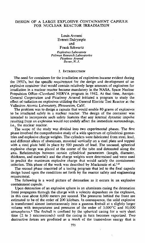
DESIGN OF A LARGE EXPLOSIVE CONTAINMENT CAPSULE FOR NUCLEAR REACTOR IRRADIATION
Louis Avrami Everett Dalrymple
and Frank Schwartz
Explosives Laboratory Feltman Research Laboratories
Picatinny Arsenal Dover, N . J .
I. INTRODUCTION
The need for containers for the irradiation of explosives became evident during the 1950’s, but the specific requirement for the design and development of an explosive container that would contain relatively large amounts of explosives for irradiation in a nuclear reactor became mandatory in the NASA, Space Nuclear Propulsion Office-Cleveland NERVA program in 1962. At that time, Aerojet- General Corporation and Picatinny Arsenal initiated a program to study the effect of radiation on explosives utilizing the General Electric Test Reactor at the Vallecitos Atomic Laboratory, Pleasanton, Calif.
The problem was to design a capsule that would enable 80 grams of explosives to be irradiated safely in a nuclear reactor. The design of the container was intended to incorporate such safety features that any internal dynamic impulse resulting from an explosion would not unduly affect the immediate surroundings, i.e., the nuclear reactor.
The scope of the study was divided into two experimental phases. The first phase involved the comprehensive study of a wide spectrum of cylindrical geome- tries and explosive charge weights. The cylinders were fabricated from steel, lead, and different alloys of aluminum, mounted vertically on a steel plate and topped with a steel plate held in place by 500 pounds of lead. The uncased, spherical explosive charge was placed at the center of the tube and detonated along the axis. Relationships between certain cylindrical parameters (length, diameter, thickness, and material) and the charge weights were determined and were used to predict the maximum explosive charge that would satisfy the containment criterion. This phase of the work was described by Mackenzie et a1.13
The second phase consisted of a testing program that led to the final capsule design based upon the conditions set forth by the reactor safety and engineering requirement.
The following is a word picture of detonation as it occurs in an explosive containment capsule.
Upon detonation of an explosive sphere in an aluminum casing the detonation front propagates through the charge with a velocity dependent on the explosive, in this case about 8,000 meters per second. The pressures behind the front are estimated to be of the order of 200 kilobars. In consequence, the solid explosive is transformed almost instantaneously into a gaseous fireball at a slightly larger volume with temperatures and pressures of the order of 3,0OO0C and 50,000 atmospheres.4 The fireball is confined by the spherical casing for a very short time (2 to 3 microseconds) until the casing in turn becomes vaporized. Two destructive forces are produced as a result of the tremendous energy that is
113
774 Annals New York Academy of Sciences
released: the shock wave and the blast pressure generated by the gases released from the explosive charge.
In otherwords, due to the detonation of the explosive charge, a pressure wave of finite amplitude is propagated into the surrounding medium. The pressure wave changes its form and, particularly in air, the pressure front becomes steeper and steeper until limited by viscosity and heat conduction. When a relatively stable form is reached, the pressure rise occurs within a very narrow region, which may be termed a perfect discontinuity. When the velocity of propagation of the disturbance is greater than the velocity of sound in the undisturbed medium, the disturbance is called a shock wave.5
The shock wave, which initially contains about one-half of the energy re- leased, propagates through the air and strikes the internal wall of the capsule. In response to the delivered impulse, the wall is given a virtually instantaneous velocity. This is true because the response time of the wall is large relative to the significant duration of the shock wave. Portions of the wall nearest the charge are given the greatest velocity and undergo the greatest deformation. The inertia and tensile strength of the capsule resist the impulsive force during the accelera- tion of the wall. Subsequently the tensile constraints bring the wall back to rest.
The explosion gases following the shock wave are confined in the capsule. The resultant internal blast pressure, a quasi-static pressure as opposed to the short-duration pressure of the shock wave is a function of the total volume of the capsule and the ability of the entire system to act as a heat sink for the gases. Distortion of the capsule wall from the shock wave precedes the arrival of the blast pressure, so that the total volume available to the explosion gases is the initial volume plus the deformation volume caused by the shock.6
In view of the above, the following explosive containment parameters have a bearing on the design of the capsule:
a. The capsule material, size, shape, and constraints. b. The magnitude and duration of the shock wave incident on the capsule
c. The inertia and dynamic tensile strength of the capsule wall. d. The heat sink capability of the total system.
a. The shock wave intensity is a function of the medium surrounding the charge.
b. The inertia of the wall is a function of the mass of the wall and its ac- celeration; the mass remains h e d , but the acceleration varies with the intensity of the shock wave and the dynamic tensile strength of the capsule wall.
C. The dynamic tensile strength of the wall depends upon the static strength of the wall, gross strain, and rate of strain. The static strength is fixed, but the strain and rate of strain vary with the intensity of the shock wave.6
wall.
The following statements are pertinent to the parameters mentioned:
11. DESIGN AND DEVELOPMENT OF CAPSULE
The design criteria were predicated on the following conditions: a. Complete integrity of the capsule. b. Containment of 80 grams of detonated explosive with a safety factor of
c. A maximum capsule diameter of 10%’’ for insertion in the water-filled two (testing with 160 grams).
reactor irradiation facility.
Avrami et al.: Large Explosive Containment Capsule 775
1000
500 - 300 - 200 -
I 2 3 5 10 20 30 INSIDE DIAMETER (d, INCHES 1
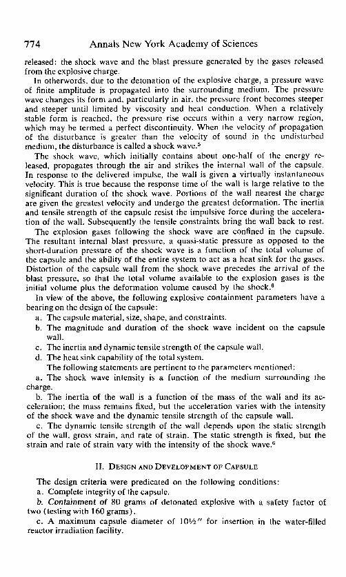
Maximum contained amount of explosive as a function of inside diameter (d) FIGURE 1. and wall thickness (e) : 6061-T6 aluminum.
776 Annals New York Academy of Sciences
Avrami et al.: Large Explosive Containment Capsule 777
. .
778 Annals New York Academy of Sciences
These conditions affected the geometry of the capsule and had a bearing on the material to be used. Combining the features required of a container material to withstand detonations and the problem of induced radioactivity and attenua- tion led to the selection of 6061-T6 aluminum as the material for the explosive containment irradiation capsule. Specific radiation factors that were considered were neutron attenuation, effect on mechanical properties and safe handling of radioactive material.
A cylindrical geometry was based upon the data obtained in the initial phase of the program by Mackenzie.R The relationships between the cylindrical para- meters and the explosive charge weight led to an equation of the form
m = ctkdb (1) Using the 6061-T6 aluminum data from the family of curves for various wall
thicknesses (FIGURE l ) , the constants were evaluated using a least squares fit to give the final equation:
m = 15.5 t1.33 d1.78
where (2)
m = maximum amount of explosive, grams t = wall thickness, inches d = inside diameter, inches
The explosive used in all testing was Composition C4 (91 % RDX, 9% Binder). The following considerations also had an effect on the general design of the
explosive container: a. Simplicity. b. Insertion and removal of container in a radiation facility in a minimum
amount of time. c. The ability to contain a large sample or samples and the ability to remove
the specimen after irradiation without destroying the container. d. Maintenance of the integrity of the container after an explosion, to permit
the controlled release of gaseous products. e. Provisions for monitoring the temperature and pressure. f . Reduction of any pressure pulse emanating from the container to preclude
any adverse effect on the surrounding medium. For complete containment, the over-all length of the container was determined
by the reflected shock waves and the volume of expanding gases. In earlier tests, the contained detonation in the cylinders, towards its upper limit, caused a bulging in the center and a flaring out on the ends. In a length to inside diameter ratio (L/D) of 6 or above, the flaring did not occur, and below 6 the flaring was eliminated by shrinking a support ring on each end and adding a closure plug or cap. The L/D ratio on the final design is 4.24. Specific shock testing on threads resulted in the selection of the buttress type thread.
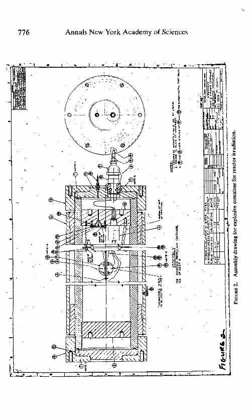
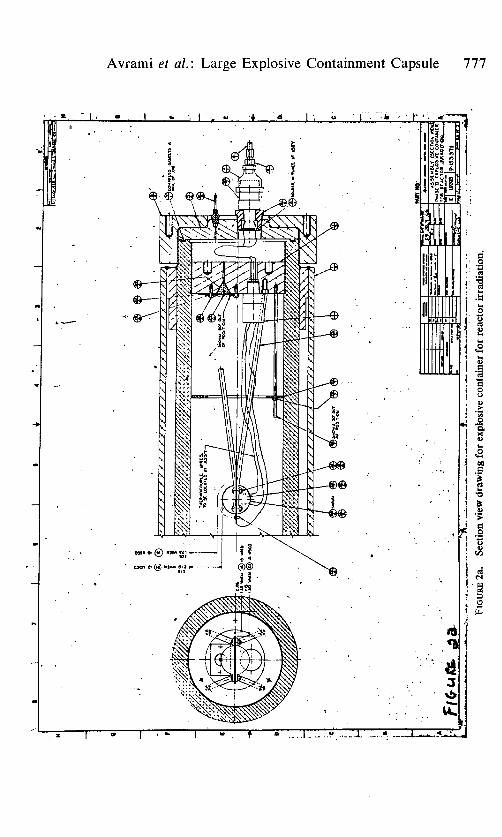
The attenuation of the shock wave or pressure pulse was affected by providing an annular space between the container and the surrounding medium, i.e., a double wall capsule. The amount of spacing was governed by the deformation or bulging in the inner wall. Expansions ranging from 8 to 10% have occurred in the O.D. near the upper limit on 6061-T6 aluminum tubes. If the weight of explosive amount was halved, the deformation was less than 2%. For shock attenuation purposes, a closure cap was also added to permit a spacing on each end (FIGURE 2) .
For instrumentation purposes, special Conax connectors that withstand static pressures up to 10,000 psi were incorporated in the container for the thermo- couple leads. These connectors as situated in FIGURE 2 easily withstand the
Avrami et al.: Large Explosive Containment Capsule 779
c 8
t .P
m W
0 6 E
780 Annals New York Academy of Sciences
OUANTIn D€SCRlPTlON I I PRESSURE WUGZ HEISE 0- IOOpi, (I-l&?.DIAl. 21.i -8 DIVISION. I / S SU8DIVIOED. WITH
REMOTE SK tWT€NTIWTER. 316 8.8.llJ8E. 2 I VACUUM W E . MARSHALLTOWN NQ 228, 2'DIAL SIZE 3 I WCUN TANK, 2000 CU. IN. I2 X 24: 8.8. 4 S 5 1
6 I
N E W ULM. wHIT€Y NO. -2-316. Vd*SIZE. 8.8. W/SIWOELOI( FITTINGS. SAFETY HEAD, SCdEW TYPE, BLACK. SMLLS e 6RBDN ASSY NO. s1-9; s.r.iOO PSA BupsTlwG PRESSURE. FILTER, NUPR0.F" SERIES WLET F U E R . CAT.NO. SS-2F-7. 540 MICRWS 1.8.
FIGURE 4. Pressure measurement panel diagram.
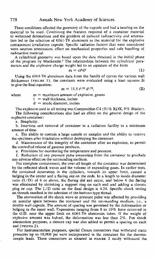
detonation of 160 grams of explosive. For pressure readings, the method de- veloped by Aeroject-General Corporation for its small capsule was used,' but the penetration in the inner plug was a pinhole lead with a recess for a conical plug in an offset position. The entire system can be evacuated or flushed with an inert gas such as helium. By maintaining a constant pressure, the pressure differential can be measured when gases are evolved from the explosive during irradiation (FIGURE 3). If the shock wave does not seal the conical plug, the gases will leak out through the pressure tube into an evacuated tank (FIGURE 4) .
The explosive with the thermocouples and flux wires was held with a spherical holder composed of two aluminum hemispheres, 0.25 inch thick, held in place by four support rods. In case of a drop, a spacer was added to minimize the deflection, so that the explosive sphere will not be too close to the wall if a detonation occurs (FIGURE 5).
Consistent with the philosophy of "maximum credible accident" which the nuclear reactor industry has followed, added restrictions were placed upon the design of the explosive containment irradiation capsule :
1. The method of detonation was changed from central initiation or along the axis (axisymetric) to lateral initiation (asymetric), so that the detonation was across the diameter of the explosive charge and perpendicular to the long axis of the capsule. In all testing, the detonations were directed towards the wall nearest to the explosive charge.
2. Drop tests were conducted from at least a 10-ft height.
Avrami et (11. : Large Explosive Containment Capsule 78 1
FIGURE 5. Explosive holder assembly.
782 Annals New York Academy of Sciences
3. The capsule was located ?A inch away from the reactor vessel wall, and all stress-strain and pressure pulses were measured for effect on the capsule and the reactor components.
111. EXPERIMENTAL INVESTIGATIONS
These added specifications had their effect on the system. The relationships derived by Mackenzie3 were no longer applicable for the specific charge weights due to the confinement of the explosive and the change in the direction of detonation.
Knowledge of the maximum expansion before rupture of 6061-T6 aluminum tubes of different diameters and wall thicknesses enabled the investigators to select the maximum permissible diameter and wall thickness and still allow for the annular space. The tube selected was 8‘’ O.D. and 6” I.D., with a 1” wall thickness.
Mackenzie’s relationship for 606 1-T6 aluminum (Equation 2) predicted that the 6” I.D. tube with a 1” wall thickness would withstand 378 grams of uncased C4 explosive detonated along the axis. Experimentally, up to 425 grams have been contained in cylinders of the same size. With the .025”-thick sphrecial aluminum casing and the direction of detonation changed 90°, the maximum explosive charge of C4 that can be contained in a S f r O.D. lff-thick 6061-T6 aluminum cylinder is 170 grams, or 45% of the predicted value.
The drop tests were conducted from a 10-ft height onto a steel plate from three different angles ( O O , 45’ and 90° relative to the axis) in order to determine that the explosive container was safe at all times. The worst condition considered possible was the shearing of the explosive holder upon impact and the detonation of the explosive upon hitting the wall. Although the support rods did hold the explosive, the deflection upon impact on the capsule’s side was too great. Tests indicated that, for proper containment, an SO-gram explosive charge cannot be detonated in an 8” O.D. lff 6061-T6 aluminum cylinder within an annular zone of %iff from the inner wall in the plane of the explosive charge. The addition of the spacer eliminated the cantilever effect and placed the location of the fulcrum at half the length of the support rods, thus substantially reducing the deflection. The spacer is also used to center the explosive sphere. For the 160-gram charge, experiments have shown that the annular zone is widened to such a degree that an off-centering of more than 3/16” from the explosive sphere would cause ruptures.
Prior to the double-wall capsule tests, a series of experiments were conducted on single-wall capsules. The single-wall capsule essentially consisted of the 8” O.D. 6” I.D. 6061-T6 aluminum cylinder with support rings shrunk-fit on the ends and threaded plugs to complete the confinement. Tests were conducted by suspending these capsules in air, and measurements of transmitted pressure pulses ?Aff away at specified locations were obtained. Also, stress levels were measured on the outer surfaces of both the single- and double-wall capsules.
The pressures transmitted to air at the center of the single-wall capsule, in the direction of firing, will not exceed 25 psi ?Aff away from the surface of the capsule. The pressure pulse may have a 2 to 3 miscrosecond rise time.9
The average permanent diametrical expansion experienced with the single- wall capsule tests was 0.2 inch, or an elongation of 2.5%. The tests indicated that the high stress levels are experienced only at the center of the capsule. Stress levels beyond * 5 inches from the center are below published static yield values.
Pre
ssu
re T
rans
duce
rs
(f"
from
su
rfac
e)
Vie
w
= S
trai
n C
ages
A-A
A-
4 I-
1"
--Ic
7
4" Al
uminum P
late
, f"
Bel
ow C
apsu
le
1 "
-
I I
G3
e I
G2
Alu
min
um C
hn
nel
a
Woo
den
Tra
nsdu
cer
Supp
ort
1st"
+
Gla
ss
-
Pla
te
Tan
k
9 6 2. 2
n ?- .. r
%
Vie
w B
-B
FIGU
RE
6.
Typ
ical
test
sch
emat
ic sh
owin
g pr
essu
re tr
ansd
ucer
s and
stra
in g
age
loca
tions
.
784 Annals New York Academy of Sciences
a B
B 8 E .I
B w
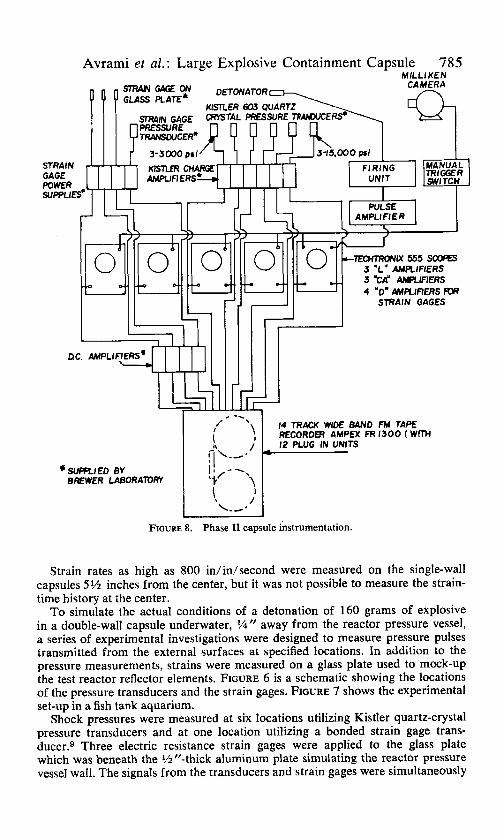
FIGURE 8. Phase I1 capsule instrumentation.
Strain rates as high as 800 in/in/second were measured on the single-wall capsules 5% inches from the center, but it was not possible to measure the strain- time history at the center.
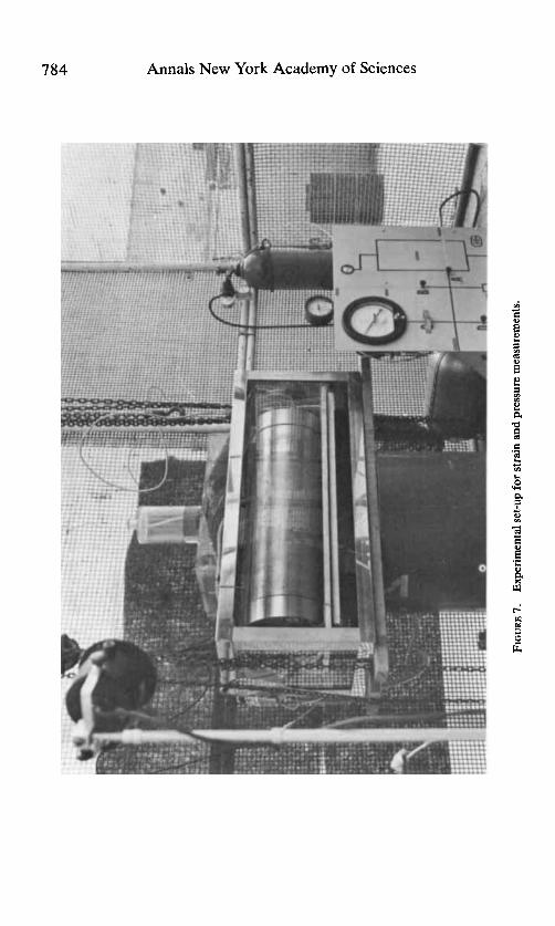
To simulate the actual conditions of a detonation of 160 grams of explosive in a double-wall capsule underwater, ?A" away from the reactor pressure vessel, a series of experimental investigations were designed to measure pressure pulses transmitted from the external surfaces at specified locations. In addition to the pressure measurements, strains were measured on a glass plate used to mock-up the test reactor reflector elements. FIGURE 6 is a schematic showing the locations of the pressure transducers and the strain gages. FIGURE 7 shows the experimental set-up in a fish tank aquarium.
Shock pressures were measured at six locations utilizing Kistler quartz-crystal pressure transducers and at one location utilizing a bonded strain gage trans- d ~ c e r . ~ Three electric resistance strain gages were applied to the glass plate which was beneath the %"-thick aluminum plate simulating the reactor pressure vessel wall. The signals from the transducers and strain gages were simultaneously
786 Annals New York Academy of Sciences
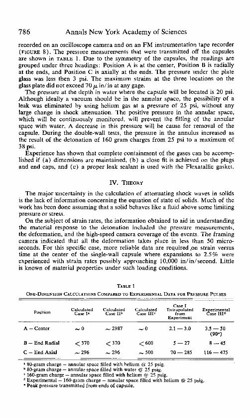
recorded on an oscilloscope camera and on an FM instrumentation tape recorder (FIGURE 8 ) . The pressure measurements that were transmitted off the capsules are shown in TABLE 1. Due to the symmetry of the capsules, the readings are grouped under three headings: Position A is at the center, Position B is radially at the ends, and Position C is axially at the ends. The pressure under the plate glass was less then 3 psi. The maximum strains at the three locations on the glass plate did not exceed 70
The pressure at the depth in water where the capsule will be located is 20 psi. Although ideally a vacuum should be in the annular space, the possibility of a leak was eliminated by using helium gas at a pressure of 25 psi, without any large change in shock attenuation. The positive pressure in the annular space, which will be continuously monitored, will prevent the filling of the annular space with water. A decrease in this pressure will be cause for removal of the capsule. During the double-wall tests, the pressure in the annulus increased as the result of the detonation of 160 gram charges from 25 psi to a maximum of 38 psi.
Experience has shown that complete containment of the gases can be accomp- lished if (a ) dimensions are maintained, (b ) a close fit is achieved on the plugs and end caps, and (c) a proper leak sealant is used with the Flexatallic gasket.
in/in at any gage.
IV. THEORY
The major uncertainty in the calculation of attenuating shock waves in solids is the lack of information concerning the equation of state of solids. Much of the work has been done assuming that a solid behaves like a fluid above some limiting pressure or stress.
On the subject of strain rates, the information obtained to aid in understanding the material response to the detonation included the pressure measurements, the deformation, and the high-speed camera coverage of the events. The framing camera indicated that all the deformation takes place in less than 50 micro- seconds. For this specific case, more reliable data are required ,on strain versus time at the center of the single-wall capsule where expansions to 2.5% were experienced with strain rates possibly approaching 10,000 in/in/second. Little is known of material properties under such loading conditions.
TABLE 1 ONE-DIMENSION CALCULATIONS COMPARED TO EXPERIMENTAL DATA FOR PRESSURE PULSES
Case I
Experiment
Calculated Calculated Calculated Extrapolated Experimental Position Case In Case I P Case IIIC from Case IIId
A - Center -0 - 2987 -0 2.1 - 3.0 3.5 - 50 (90")
B-EndRadial <370 <370 < 600 5 -27 8 - 45
C - End Axial - 296 - 296 - 500 70 - 285 116 - 475
a 80-gram charge - annular space filled with helium @ 25 psig. 80-gram charge - annular space filled with water @I 25 psig. 160-gram charge - annular space filled with helium @ 25 psig. Experimental - 160-gram charge - annular space filled with helium @ 25 psig. Peak pressure transmitted from ends of capsule.
Avrami et al.: Large Explosive Containment Capsule 787
However, Perrone'O has devised a simplified method for solving impulsively loaded structures of rate-sensitive materials. He assumed the yield stress-strain- rate law to be of the form.
where E = strain rate r,, = static yield stress (when E = 0) u = dynamic yield stress
D, n = material constants
With n = 4 and D = 6,50O/sec for 6061 aluminum at 1,00O/sec, a value of about 1.5 is realized for the yield stress (normalized) u/uo. What effect the orientation of the detonation had on the uniformity of the impulse or the ring in this case is not known. Also, strain rates for 6061 aluminum were not shown above 1,00O/sec.
In an effort to develop a mathematical model to calculate the pressures at the specified locations, several approaches were tried. A one-dimensional Lagrangian hydrodynamic code was the first attempt. This was a one-dimensional spherical calculation of the free expansion of a centrally initiated sphere of explosive into a spherical cavity and the subsequent interaction of the gases with a rigid spherical boundary. The equation of state for the detonation products of Composition B was used instead of C4. Air in the cavity and .the motion of the wall were neglected. Because of the cylindrical geometry, only the initial pressure at the wall was obtained. The result for the peak pressure at the surface of the inner wall was 30 kilobars for a 160-gram charge. The experimental values indicate that the value obtained was at least an order of magnitude too high.
Lawrence Radiation Laboratory has been requested to use a computer code referred to as the Hemp Code," which can be used to calculate the stress, strain, and pressure at each point (two-dimensional) of a model configuration (FIGURE 9) , at a series of time increments, resulting from the detonation of an explosive. Three cases are to be considered:
- 80-gram charge Comp B - annular space filled with helium at Case1
Case I1 - 80-gram charge Comp B - annular space filled with water. Case 111 - 160-gram charge Comp B - annular space filled with helium at
Cases I and TI will simulate the irradiation test conditions both with and without water in the annular space. Case 111 simulates the qualification test conditions.
The results of these calculations were expected from the laboratory in October 1966.
Meanwhile, one-dimensional impedance miss-match calculations using the same model (FIGURE 9 ) were made utilizing the scaling In order to make analytical calculations, the following assumptions were made:
a. According to size scaling, the peak overpressure (Pr ) and scaled im- pulse (l/Wh) are functions of the scaled distance (R/WTS) where R is the distance from the center of the explosive sphere and W is the weight of the charge.
25 psig.
25 psig.
b. PrTNT Pr camp B
788 Annals New York Academy of Sciences
Avrami at al.: Large Explosive Containment Capsule 789
FIGURE 10. Pressures and velocities in capsule with 80-gram detonation and water in annular space.
790 Annals New York Academy of Sciences
c. The pressure pulses are approximated by square waves whose durations are longer than the transit times (unattenuated shocks).
d. At low pressures, the pressure can be approximated by a linear function of the particle velocity P = k up (Reference 14).
Calculations were made for each case at each of the three positions shown in FIGURE 9.15 This method assumes no transmission losses, and so higher pressures than those observed are predicted (TABLE 1 ) . Even with the assumptions made, the relative magnitudes should be correct. The values show a 40% decrease in peak shock pressure when the explosive weight is reduced from 160 to 80 grams. This ratio was used to predict the extrapolated shock pressures that would be observed if 80 grams were detonated in the capsule.
FIGURE 10 shows graphically the pressures and particle velocities as a function of time and position for Case 11, Position A, which was the point at the center when an 80-gram charge detonates with the annular space filled with water. This is the worst possible case, which indicates that a transient pulse of about 3,000 psi would be transmitted to the reactor.
Good agreement with the experimental data is shown with all the values except Position B. The wide difference in these values is probably due to the obliqueness of the shock. The results that were obtained for the 160-gram charge and the annular space filled with helium-5.0 psi maximum off the center, 45 psi maximum radially off the ends and 475 psi maximum off the ends axially- demonstrate that the shock waves have been attenuated to such an extent that the detonation of an 80-gram charge during irradiation would produce negligible effects in the surrounding medium.
Summarizing, it is believed that the major problem areas in the design of a large explosive containment irradiation capsule have been solved and that an 80-gram sample of explosive can be irradiated safely.
ACKNOWLEDGMENTS
This work has been supported by NASA-SNPO-C for the past three years. Current funds are from NASA Defense Purchase Request SNC-3.
The assistance and encouragement of the following persons are gratefully acknowledged. Dr. J. V. R. Kaufman, Chief Scientist, Munitions Command, for initiating the program. Dr. H. J . Matsuguma, Picatinny Arsenal, for his sug- gestions and criticisms. We extend our deepest appreciation to Mr. H. Smith from SNPO-C and Messrs J. R. Norman, M. E. Downs, W. E. Voreck and E. Lindberg from Aerojet-General Corporation. Mr. E. E. Walbrecht’s assistance with the instrumentation is also appreciated.
REFERENCES 1. MACKENZIE, A. & E. W. DALRYMPLE. 1963. The Dependence of Dynamic Strength of
Cylindrical Pressure Vessels on Geometrical Parameters. Picatinny Arsenal Technical Memorandum 1206. (May, 1963.)
2. MACKENZIE, A. & E. W. DALRYMPLE. 1964. Burst Test Results Simplified Design of Irradiation Capsules for Explosive Materials. Nucleonics 22(2) : 85. (February, 1964.)
3. MACKENZIE, A., E. W. DALRYMPLE & F. SCHWARTZ. 1965. Design of Pressure Vessels for Confining Explosives. Picatinny Arsenal Technical Memorandum 1643. (July, 1965.)
4. COLE, R. N. 1948. Underwater Explosions. Princeton University Press, Princeton, N. J. 5 . DORAN, D. G. & R. K. LINDE. 1965. Shock Effects in Solids. Stanford Research Institute
6. WISE, W. R., JR. & J. F. PROCTOR. 1965. Explosion Containment Laws for Nuclear Poulter Laboratories Technical Report 0 0 4 6 5 . (November, 1965.)
Reactor Vessels. NOLTR-63-140. August.
Avrami et (11. : Large Explosive Containment Capsule 79 1
7. Final Test Specifications for Phase I-C of the Countermeasures Radiation Effects Program, Addendum No. 4 to AGC-REON Report No. 2510, July 1964. Volume I.
8. VANSTONE, R. A.1966. Phase 11 Irradiation Capsule Tests, Strain Stress and Pressure Data. Brewer Engineering Laboratories Reoort No. 332. Contract No. DA-28-017- AMC-3093(A). Xpril. -
9. VANSTONE, R. A. 1966. Phase I1 Irradiation Capsule Tests Strain and Pressure Data, Brewer Engineering Laboratories Report No. 337. Contract No. DA-28-017-AMC- 3541(A). April. -
10. PERRONE, N. 1965. On a Simplified Method for Solving Impulsively Loaded Structures of Rate-Sensitive Materials. Journal of Applied Mechanics, Vol. 32 Trans. ASME, Vol. 87, Series E:489. September.
11. Methods of Computational Physics, 1964. 3: 21 1. Academic Press, Inc. New York, N. Y. 12. GRANSTROM, SUNE A. 1956. Loading characteristics of air blasts from detonating charges.
Transactions of the Royal Institute of Technology, Stockholm, Sweden. 13. AMMAN & WHITNEY. 1963. Industrial engineering study to establish safety design criteria
for use in engineering of explosive facilities and operations-wall response. Contract DA-28-017-501-ORD-3889. April.
14. RICE, M. H., R. G. MCQUEEN & J. M. WALSH. 1958. Solid State Physics, F. Seitz & D. Turnbull, Eds. Academic Press, Inc. New York, N. Y. 6: 1.
15. Private communication. Letter from L. Avrami to C. M. Rice, Aerojet-General Corpora- tion, dated August 3, 1966.


![CDNPIULNIliU - UNT Digital Library/67531/metadc866127/..., To: Mr. L. M. Raring Tab].a 1 Status of UC Irradiation Testing ICf/o Enricheid, 2200? Capsule r.cjir.~:.';ion FW26-ipO 151](https://img.pdfslide.net/doc/110x75/5f48ce6c0dfe95573e7ba9fa/cdnpiulniliu-unt-digital-library-67531metadc866127-to-mr-l-m-raring.jpg)