Embed Size (px)
Citation preview
TECHNICAL PAPER
Design of an auto-focusing actuator with a flexure-basedcompliant mechanism for mobile imaging devices
Choong Kim • Myeong-Gyu Song • YoungJun Kim •
No-Cheol Park • Kyoung-Su Park • Young-Pil Park •
Kyung Sik Shin • Jeen Gi Kim • Geum Sik Lee
Received: 31 October 2012 / Accepted: 15 June 2013 / Published online: 27 June 2013
� Springer-Verlag Berlin Heidelberg 2013
Abstract There is increasing consumer’s demand for
high-quality and high-performance mobile imaging devi-
ces. In this paper, an auto-focusing (AF) actuator with a
flexure hinge that uses the electromagnetic (EM) circuit of
a voice coil motor was designed and evaluated. The flexure
hinge was designed by using finite element analysis. The
EM circuit was designed based on the structural stiffness of
the device. The EM circuit was analyzed using the design
of experiments procedure. Based on the results, the effec-
tive design parameters were selected, and improvements
were made to the design. Finally, a prototype of the AF
actuator was manufactured, and the feasibility and perfor-
mance of the actuator with the flexure hinge were verified
experimentally. The experimental results indicated that the
proposed actuator performed adequately and satisfied the
design requirements.
1 Introduction
The demand for high performance and high quality of auto-
focusing (AF) camera module as digital imaging devices,
such as cellular phones and digital video cameras has been
increased in many industries and research center to meet the
requirements of the customers. AF actuator is divided into
two parts: driving mechanism to shift the moving part,
which consisted of lens holder, lenses, and permanent
magnet, and supporting mechanism to hold the moving part.
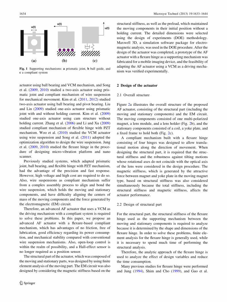
Representative types of AF driving mechanism are
divided into voice coil motors (VCMs), piezoelectric
motors (PZTs), and enhanced crystals or liquid lenses.
VCMs are mainly used as driving mechanism of AF
because of the advantages of fine motion, cost effective-
ness, ease of fabrication, and structural stability. And, as
shown in Fig. 1, supporting mechanisms are divided into
three types: prismatic joints, ball bearing, and compliant
systems. Each mechanism has advantages and disadvan-
tages. Prismatic joints, which use shaft guides as a sup-
porting mechanism, have the advantage of mechanical
stability and the disadvantage of excessive friction. Com-
pliant systems using a wire suspension have poor
mechanical stability but do not suffer from friction prob-
lems. Ball guides have been mainly used as supporting
mechanisms because of their simple structure and low
rolling friction.
Researches of supporting mechanisms have been con-
stantly increased to meet the demand for higher mechanical
stability, better reliability, and lower cost. The main factors
for these studies to select an appropriate driving and sup-
porting mechanisms are the friction force and mechanical
stability because these factors are related with the perfor-
mance of the AF actuator. Therefore, the wire suspension
and flexure hinge as compliant systems are studied and
adopted as supporting mechanism because of the advantage
of the friction free.
Examples of previous studies include the following. Yu
and Liu (2007) and Yeom (2009) studied a two-axis
C. Kim � M.-G. Song � Y. Kim
Center for Information Storage Device,
Yonsei University, Seoul, South Korea
N.-C. Park (&) � K.-S. Park � Y.-P. Park
Department of Mechanical Engineering,
Yonsei University, Seoul, South Korea
e-mail: [email protected]
URL: http://optomecha.yonsei.ac.kr/index.html
K. S. Shin � J. G. Kim � G. S. Lee
R&D Center, MuTas Inc., 332-2 Factory World Suite
401,Wonchon-Dong, Youngtong-Gu, Suwon 442-374,
South Korea
123
Microsyst Technol (2013) 19:1633–1644
DOI 10.1007/s00542-013-1873-1
actuator using ball bearing and VCM mechanism, and Song
et al. (2009, 2010) studied a two-axis actuator using pris-
matic joint and compliant mechanism of wire suspension
for mechanical movement. Kim et al. (2011, 2012) studied
two-axis actuator using ball bearing and pivot bearing. Liu
and Lin (2009) studied one-axis actuator using prismatic
joint with and without holding current. Kim et al. (2009)
studied one-axis actuator using cam structure without
holding current. Zhang et al. (2006) and Li and Xu (2009)
studied compliant mechanism of flexible hinge with PZT
mechanism. Woo et al. (2010) studied the VCM actuator
using wire suspension and Song et al. (2011) adopted the
optimization algorithm to design the wire suspension. Jung
et al. (2009, 2010) studied the flexure hinge in the proce-
dure of designing micro-vibration platform and nano
scanner.
Previously studied systems, which adapted prismatic
joint, ball bearing, and flexible hinge with PZT mechanism,
had the advantage of the precision and fast response.
However, high voltage and high cost are required to do so.
Also, wire suspensions as compliant mechanism suffer
from a complex assembly process to align and bond the
wire suspension, which holds the moving and stationary
components, and have difficulty aligning the centers of
mass of the moving components and the force generated by
the electromagnetic (EM) circuit.
Therefore, an advanced AF actuator that uses a VCM as
the driving mechanism with a compliant system is required
to solve these problems. In this paper, we propose an
advanced AF actuator with a flexure-based compliant
mechanism, which has advantages of no friction, free of
lubrication, good efficiency regarding its power consump-
tion, and mechanical stability compared with conventional
wire suspension mechanisms. Also, open-loop control is
within the realm of possibility, and a Hall-effect sensor is
no longer required as a position sensor.
The structural part of the actuator, which was composed of
the moving and stationary parts, was designed by using finite
element analysis of the moving part. The EM circuit was also
designed by considering the magnetic stiffness based on the
structural stiffness, as well as the preload, which maintained
the moving components in their initial position without a
holding current. The detailed dimensions were selected
using the design of experiments (DOE) methodology.
Maxwell 3D, a simulation software package for electro-
magnetic analysis, was used in the DOE procedure. After the
design of the actuator was completed, a prototype of the AF
actuator with a flexure hinge as a supporting mechanism was
fabricated for a mobile imaging device, and the feasibility of
adapting the AF actuator using a VCM as a driving mecha-
nism was verified experimentally.
2 Design of the actuator
2.1 Overall structure
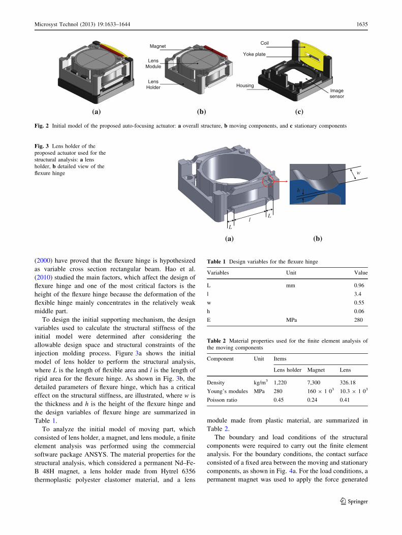
Figure 2a illustrates the overall structure of the proposed
AF actuator, consisting of the structural part (including the
moving and stationary components) and the EM circuit.
The moving components consisted of one multi-polarized
magnet, a lens module, and a lens holder (Fig. 2b), and the
stationary components consisted of a coil, a yoke plate, and
a fixed frame to hold both (Fig. 2c).
A compliant mechanism built with a flexure hinge
consisting of four hinges was designed to allow transla-
tional motion along the direction of movement. When
designing the structural part, it is required that the struc-
tural stiffness and the robustness against tilting motions
whose rotational axes do not coincide with the optical axis
of the lens were considered in the design procedure. The
magnetic stiffness, which is generated by the attractive
force between magnet and yoke plate in the moving magnet
type, based on structural stiffness was also considered
simultaneously because the total stiffness, including the
structural stiffness and magnetic stiffness, affects the
actuator performance.
2.2 Design of structural part
For the structural part, the structural stiffness of the flexure
hinge used as the supporting mechanism between the
moving and stationary components is required to analyze
because it is determined by the shape and dimensions of the
flexure hinge. In order to solve these problems, finite ele-
ment analysis for the flexure hinge is generally used, while
it is necessary to spend much time of performing the
structural analysis.
Therefore, the analytic approach of the flexure hinge is
used to analyze the effect of design variables and reduce
the time consumption.
Many previous studies for flexure hinge were performed
and Jung (1994), Shim and Cho (1999), and Guo et al.
u(t)u(t)
u(t)
(a) (b) (c)
Fig. 1 Supporting mechanisms: a prismatic joint, b ball guide, and
c a compliant system
1634 Microsyst Technol (2013) 19:1633–1644
123
(2000) have proved that the flexure hinge is hypothesized
as variable cross section rectangular beam. Hao et al.
(2010) studied the main factors, which affect the design of
flexure hinge and one of the most critical factors is the
height of the flexure hinge because the deformation of the
flexible hinge mainly concentrates in the relatively weak
middle part.
To design the initial supporting mechanism, the design
variables used to calculate the structural stiffness of the
initial model were determined after considering the
allowable design space and structural constraints of the
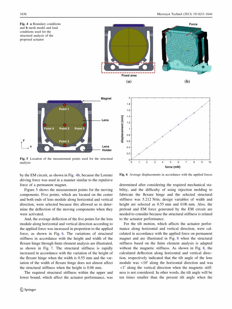
injection molding process. Figure 3a shows the initial
model of lens holder to perform the structural analysis,
where L is the length of flexible area and l is the length of
rigid area for the flexure hinge. As shown in Fig. 3b, the
detailed parameters of flexure hinge, which has a critical
effect on the structural stiffness, are illustrated, where w is
the thickness and h is the height of the flexure hinge and
the design variables of flexure hinge are summarized in
Table 1.
To analyze the initial model of moving part, which
consisted of lens holder, a magnet, and lens module, a finite
element analysis was performed using the commercial
software package ANSYS. The material properties for the
structural analysis, which considered a permanent Nd–Fe-
B 48H magnet, a lens holder made from Hytrel 6356
thermoplastic polyester elastomer material, and a lens
module made from plastic material, are summarized in
Table 2.
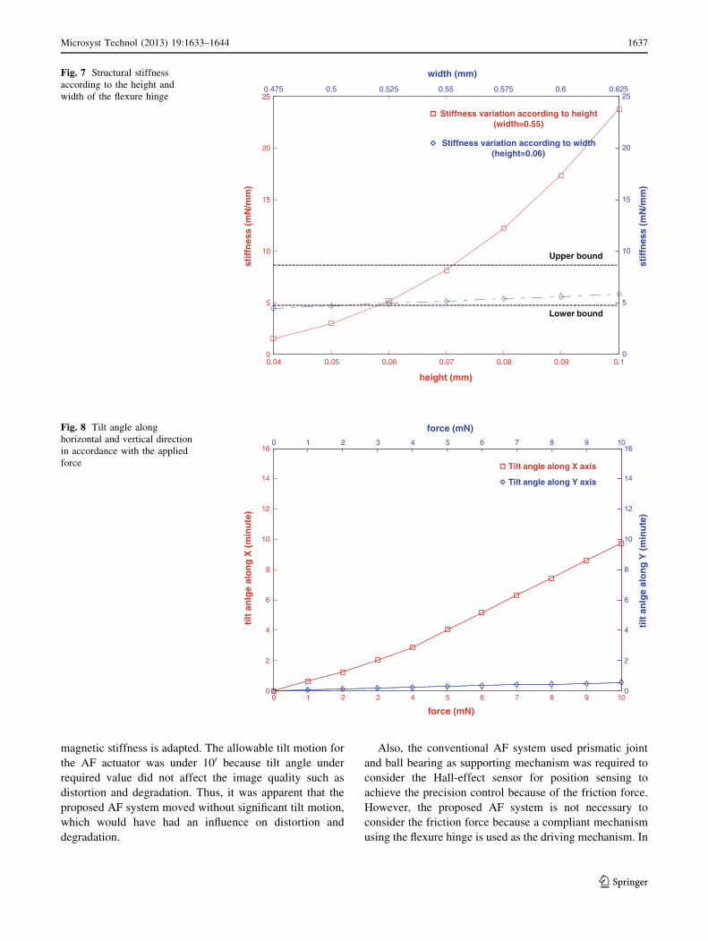
The boundary and load conditions of the structural
components were required to carry out the finite element
analysis. For the boundary conditions, the contact surface
consisted of a fixed area between the moving and stationary
components, as shown in Fig. 4a. For the load conditions, a
permanent magnet was used to apply the force generated
Image sensor
Lens Holder
Magnet
Lens Module
Coil
Housing
Yoke plate
(a) (b) (c)
Fig. 2 Initial model of the proposed auto-focusing actuator: a overall structure, b moving components, and c stationary components
h
w
Ll
L
(a) (b)
Fig. 3 Lens holder of the
proposed actuator used for the
structural analysis: a lens
holder, b detailed view of the
flexure hinge
Table 1 Design variables for the flexure hinge
Variables Unit Value
L mm 0.96
l 3.4
w 0.55
h 0.06
E MPa 280
Table 2 Material properties used for the finite element analysis of
the moving components
Component Unit Items
Lens holder Magnet Lens
Density kg/m3 1,220 7,300 326.18
Young’s modules MPa 280 160 9 1 03 10.3 9 1 03
Poisson ratio 0.45 0.24 0.41
Microsyst Technol (2013) 19:1633–1644 1635
123
by the EM circuit, as shown in Fig. 4b, because the Lorentz
driving force was used in a manner similar to the repulsive
force of a permanent magnet.
Figure 5 shows the measurement points for the moving
components. Five points, which are located on the center
and both ends of lens module along horizontal and vertical
direction, were selected because this allowed us to deter-
mine the deflection of the moving components when they
were activated.
And, the average deflection of the five points for the lens
module along horizontal and vertical direction according to
the applied force was increased in proportion to the applied
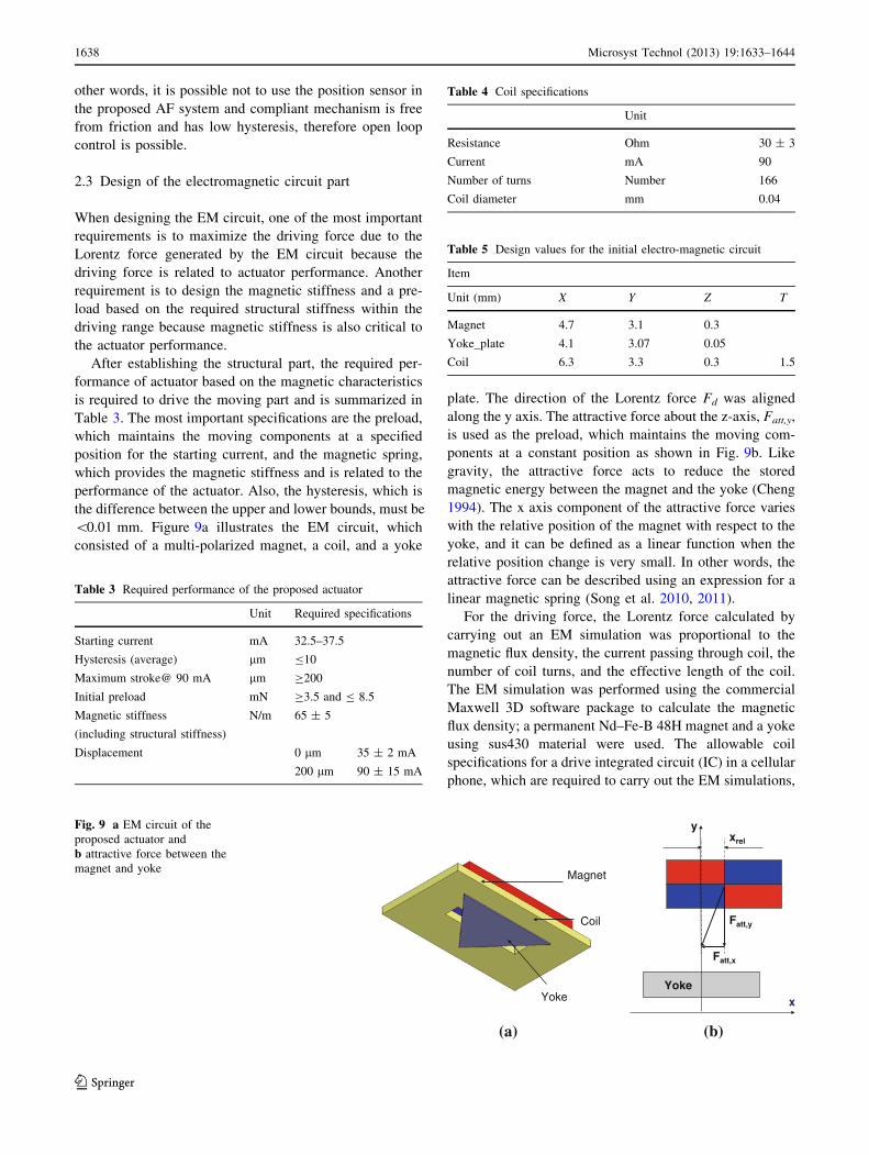
force, as shown in Fig. 6. The variations of structural
stiffness in accordance with the height and width of the
flexure hinge through finite element analysis are illustrated,
as shown in Fig. 7. The structural stiffness is rapidly
increased in accordance with the variation of the height of
the flexure hinge when the width is 0.55 mm and the var-
iation of the width of flexure hinge does not almost affect
the structural stiffness when the height is 0.06 mm.
The required structural stiffness within the upper and
lower bound, which affect the actuator performance, was
determined after considering the required mechanical sta-
bility, and the difficulty of using injection molding to
fabricate the flexure hinge and the selected structural
stiffness was 5.212 N/m; design variables of width and
height are selected as 0.55 mm and 0.06 mm. Also, the
preload and EM force generated by the EM circuit are
needed to consider because the structural stiffness is related
to the actuator performance.
For the tilt motion, which affects the actuator perfor-
mance along horizontal and vertical direction, were cal-
culated in accordance with the applied force on permanent
magnet and are illustrated in Fig. 8 when the structural
stiffness based on the finite element analysis is adapted
without the magnetic stiffness. As shown in Fig. 8, the
calculated deflection along horizontal and vertical direc-
tion, respectively indicated that the tilt angle of the lens
module was \100 along the horizontal direction and was
\10 along the vertical direction when the magnetic stiff-
ness is not considered. In other words, the tilt angle will be
ten times smaller than the present tilt angle when the
Force
Fixed area
(a) (b)
Fig. 4 a Boundary conditions
and b mesh model and load
conditions used for the
structural analysis of the
proposed actuator
Point 1
Point 2
Point 3
Magnet
Lens
Lens Holder
Point 4 Point 5
x
y
Fig. 5 Location of the measurement points used for the structural
analysis 0 1 2 3 4 5 6 7 8 9 100
0.2
0.4
0.6
0.8
1
1.2
1.4
1.6
1.8
2
force (mN)
dis
pla
cem
ent
(mm
)
Fig. 6 Average displacements in accordance with the applied forces
1636 Microsyst Technol (2013) 19:1633–1644
123
magnetic stiffness is adapted. The allowable tilt motion for
the AF actuator was under 100 because tilt angle under
required value did not affect the image quality such as
distortion and degradation. Thus, it was apparent that the
proposed AF system moved without significant tilt motion,
which would have had an influence on distortion and
degradation.
Also, the conventional AF system used prismatic joint
and ball bearing as supporting mechanism was required to
consider the Hall-effect sensor for position sensing to
achieve the precision control because of the friction force.
However, the proposed AF system is not necessary to
consider the friction force because a compliant mechanism
using the flexure hinge is used as the driving mechanism. In
0.04 0.05 0.06 0.07 0.08 0.09 0.10
5
10
15
20
25
height (mm)
stif
fnes
s (m
N/m
m)
0.48 0.5 0.52 0.54 0.56 0.58 0.6 0.62
0
5
10
15
20
25
width (mm)
stif
fnes
s (m
N/m
m)
0.475 0.5 0.525 0.55 0.575 0.6 0.625
Stiffness variation according to height (width=0.55)
Stiffness variation according to width (height=0.06)
Lower bound
Upper bound
Fig. 7 Structural stiffness
according to the height and
width of the flexure hinge
0 1 2 3 4 5 6 7 8 9 100
2
4
6
8
10
12
14
16
force (mN)
tilt
an
lge
alo
ng
X (
min
ute
)
0 1 2 3 4 5 6 7 8 9 10
0
2
4
6
8
10
12
14
16
force (mN)
tilt
an
lge
alo
ng
Y (
min
ute
)
Tilt angle along X axis
Tilt angle along Y axis
Fig. 8 Tilt angle along
horizontal and vertical direction
in accordance with the applied
force
Microsyst Technol (2013) 19:1633–1644 1637
123
other words, it is possible not to use the position sensor in
the proposed AF system and compliant mechanism is free
from friction and has low hysteresis, therefore open loop
control is possible.
2.3 Design of the electromagnetic circuit part
When designing the EM circuit, one of the most important
requirements is to maximize the driving force due to the
Lorentz force generated by the EM circuit because the
driving force is related to actuator performance. Another
requirement is to design the magnetic stiffness and a pre-
load based on the required structural stiffness within the
driving range because magnetic stiffness is also critical to
the actuator performance.
After establishing the structural part, the required per-
formance of actuator based on the magnetic characteristics
is required to drive the moving part and is summarized in
Table 3. The most important specifications are the preload,
which maintains the moving components at a specified
position for the starting current, and the magnetic spring,
which provides the magnetic stiffness and is related to the
performance of the actuator. Also, the hysteresis, which is
the difference between the upper and lower bounds, must be
\0.01 mm. Figure 9a illustrates the EM circuit, which
consisted of a multi-polarized magnet, a coil, and a yoke
plate. The direction of the Lorentz force Fd was aligned
along the y axis. The attractive force about the z-axis, Fatt,y,
is used as the preload, which maintains the moving com-
ponents at a constant position as shown in Fig. 9b. Like
gravity, the attractive force acts to reduce the stored
magnetic energy between the magnet and the yoke (Cheng
1994). The x axis component of the attractive force varies
with the relative position of the magnet with respect to the
yoke, and it can be defined as a linear function when the
relative position change is very small. In other words, the
attractive force can be described using an expression for a
linear magnetic spring (Song et al. 2010, 2011).
For the driving force, the Lorentz force calculated by
carrying out an EM simulation was proportional to the
magnetic flux density, the current passing through coil, the
number of coil turns, and the effective length of the coil.
The EM simulation was performed using the commercial
Maxwell 3D software package to calculate the magnetic
flux density; a permanent Nd–Fe-B 48H magnet and a yoke
using sus430 material were used. The allowable coil
specifications for a drive integrated circuit (IC) in a cellular
phone, which are required to carry out the EM simulations,
Table 3 Required performance of the proposed actuator
Unit Required specifications
Starting current mA 32.5–37.5
Hysteresis (average) lm B10
Maximum stroke@ 90 mA lm C200
Initial preload mN C3.5 and B 8.5
Magnetic stiffness
(including structural stiffness)
N/m 65 ± 5
Displacement 0 lm 35 ± 2 mA
200 lm 90 ± 15 mA
Magnet
Coil
Yoke
xrel
Fatt,x
Fatt,y
Yokex
y
(a) (b)
Fig. 9 a EM circuit of the
proposed actuator and
b attractive force between the
magnet and yoke
Table 4 Coil specifications
Unit
Resistance Ohm 30 ± 3
Current mA 90
Number of turns Number 166
Coil diameter mm 0.04
Table 5 Design values for the initial electro-magnetic circuit
Item
Unit (mm) X Y Z T
Magnet 4.7 3.1 0.3
Yoke_plate 4.1 3.07 0.05
Coil 6.3 3.3 0.3 1.5
1638 Microsyst Technol (2013) 19:1633–1644
123
are summarized in Table 4. Here, the coil resistance was
30 ± 3 X, the coil diameter was 40.0 lm, and the number
of coil turns was 166. Table 5 lists the design values of the
initial magnetic circuit.
After establishing a structure for the proposed actuator,
a finite element analysis of the EM circuit was carried out.
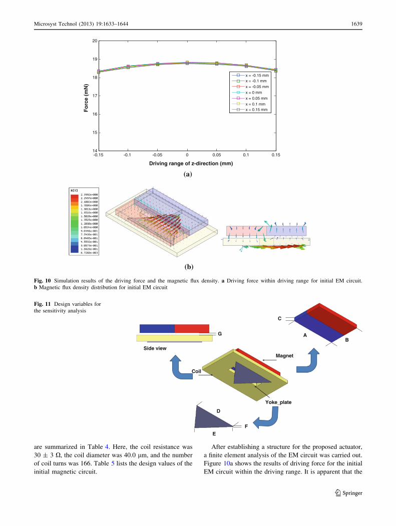
Figure 10a shows the results of driving force for the initial
EM circuit within the driving range. It is apparent that the
-0.15 -0.1 -0.05 0 0.05 0.1 0.1514
15
16
17
18
19
20
Driving range of z-direction (mm)
Fo
rce
(mN
)
x = -0.15 mmx = -0.1 mm
x = -0.05 mm
x = 0 mm
x = 0.05 mm
x = 0.1 mmx = 0.15 mm
(a)
(b)
Fig. 10 Simulation results of the driving force and the magnetic flux density. a Driving force within driving range for initial EM circuit.
b Magnetic flux density distribution for initial EM circuit
Magnet
Yoke_plate
Coil
Side view
AB
C
D
EF
G
Fig. 11 Design variables for
the sensitivity analysis
Microsyst Technol (2013) 19:1633–1644 1639
123
driving force is well distributed regardless of the driving
range along horizontal and vertical direction, as shown in
Fig. 10a. Although the EM circuit was open, as shown in
Fig. 10b, the flux from the magnet was transferred well to
the coil because the gap between the magnet and the coil
was sufficiently small. The intensity of the flux was
determined by the material properties of the magnet and
affected the EM force.
The values of the initial preload and magnetic stiffness
were 2.346 mN and 35.64 N/m. However, these did not
meet the required specifications for the actuator. Although
the driving force exhibited satisfactory performance for the
movement, the preload and the magnetic spring is required
to be.
The magnetic spring and preload of the initial model did
not satisfy their desired requirements and required
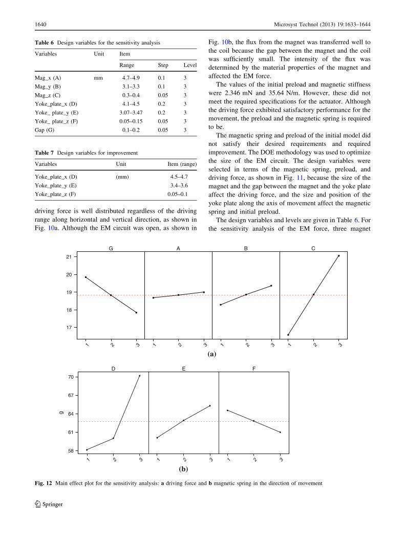
improvement. The DOE methodology was used to optimize
the size of the EM circuit. The design variables were
selected in terms of the magnetic spring, preload, and
driving force, as shown in Fig. 11, because the size of the
magnet and the gap between the magnet and the yoke plate
affect the driving force, and the size and position of the
yoke plate along the axis of movement affect the magnetic
spring and initial preload.
The design variables and levels are given in Table 6. For
the sensitivity analysis of the EM force, three magnet
Table 6 Design variables for the sensitivity analysis
Variables Unit Item
Range Step Level
Mag_x (A) mm 4.7–4.9 0.1 3
Mag_y (B) 3.1–3.3 0.1 3
Mag_z (C) 0.3–0.4 0.05 3
Yoke_plate_x (D) 4.1–4.5 0.2 3
Yoke_ plate_y (E) 3.07–3.47 0.2 3
Yoke_ plate_z (F) 0.05–0.15 0.05 3
Gap (G) 0.1–0.2 0.05 3
CBAG
321321321321
21
20
19
18
17
(a)
FED
321321321
70
67
64
61
58
g
(b)
Fig. 12 Main effect plot for the sensitivity analysis: a driving force and b magnetic spring in the direction of movement
Table 7 Design variables for improvement
Variables Unit Item (range)
Yoke_plate_x (D) (mm) 4.5–4.7
Yoke_plate_y (E) 3.4–3.6
Yoke_plate_z (F) 0.05–0.1
1640 Microsyst Technol (2013) 19:1633–1644
123
strengths were considered, considering the structural con-
straints and driving range. These were denoted as mag_x
(A), mag_y (B), and mag_z (C). Three sizes of the air gap
(G) between the permanent magnet and the yoke plate were
also considered. The design variables of the yoke plate,
denoted as yoke_plate_x (D), yoke_plate_y (E), and
yoke_plate_z (F), were selected for the sensitivity analysis
of the magnetic spring. Finite element analysis of the EM
circuit was used for the sensitivity analysis.
The results of the sensitivity analysis used to maximize
the EM force are shown in Fig. 12a and the sensitivity
analysis for the magnetic spring was used to meet the
requirements of the upper and lower bounds of the move-
ment, considering the constraint of the preload, as also
shown in Fig. 12b.
As shown in Fig. 12a, design variable C is the most
sensitive and design variable G is more sensitive than the
design variables A and B. Based on the sensitivity analysis
for EM force and the interaction between the design vari-
ables, the sizes of the magnet and air gap were first chosen
to maximize the EM force.
And then, other design variables were selected to control
the magnetic spring, which affect DC sensitivity. As shown
in Fig. 12b, the most sensitive level of the yoke_plate was
selected for the magnetic spring and the range of the design
variables of the yoke-plate for the improvement of mag-
netic spring are summarized in Table 7. The objective
function to satisfy the magnetic spring considering the
structural stiffness is derived in Eq. (1). The preload and
starting current to affect the attractive force about driving
axis, that is normal force between the magnet and yoke_-
plate, are selected as constraints. The attractive force,
which can maintain the mover on the same position, can be
expressed as the normal force about the driving axis. The
objective function was defined in Eq. (1) and the gradient-
based optimization was carried out.
Minimize
ffiffiffiffiffiffiffiffiffiffiffiffiffiffiffiffiffiffiffiffiffiffiffiffiffiffiffiffiffiffiffiffiffiffiffiffiffiffiffiffiffiffiffiffiffiffiffiffiffiffiffiffiffiffiffiffiffiffiffiffiffiffiffiffiffiffiffiffiffiffiffiffiffiffiffiffiffiffiffiffiffiffiffiffiffiffiffiffiffiffiffiffiffiffiffi
Kmagnetic;i � Kt;desired
� �2þ Kstructural;i � Kt;desired
� �2q
ð1Þ
Constraint #1.
Fv � Fg � normal force � Fv þ Fg
Constraint #2.
30 [mA] B starting current B 45 [mA].
where the variables Kmagnetic,i and Kstructural,i are the
magnetic and structural stiffness for the finite element
0 1 2 3 4 5 6 7 8 9 10 11 12 13 14 150
10
20
30
40
50
60
70
80
Iteration
Ob
ject
ive
fun
ctio
n
Fig. 13 Improvement
procedure using gradient-based
optimization
Table 8 Design values for the improved electro-magnetic circuit
Item
Unit (mm) X Y Z T
Magnet 4.7 3.3 0.4
Yoke_plate 4.53 3.47 0.053
Coil 6.3 3.3 0.3 1.5
Table 9 Comparison of the initial model with the improved model
Unit Initial
model
Improved
model
Initial preload mN 2.346 7.153
Magnetic stiffness
(including structural stiffness)
N/m 35.64 65.834
Microsyst Technol (2013) 19:1633–1644 1641
123
analysis during iteration in the driving direction, respec-
tively; Kt,desired is the desired value of the magnetic spring.
Fv is the generated force at starting current, and Fg is the
weight of the mover.
Based on the above-mentioned structural and magnetic
stiffness, the improvement procedure was performed by
changing the levels of the design variables and the objec-
tive function was converged to the desired value as shown
in Fig. 13. The improved design variables are summarized
in Table 8, and the performance of the initial and improved
models is compared in Table 9.
The magnetic spring along the direction of movement
was 65.834 N/m and the preload was 7.153 mN for the
improved model. Therefore, through this improvement
procedure, the magnetic characteristics, which are related
to the performance of the actuator, were altered to meet the
desired values. After the sensitivity analysis and resulting
design improvements, the magnetic stiffness was increased
by 84.7 % to 65.834 N/m and the preload was improved by
204.9 % to 7.153 mN in the direction of movement.
3 Fabrication and testing of the prototype
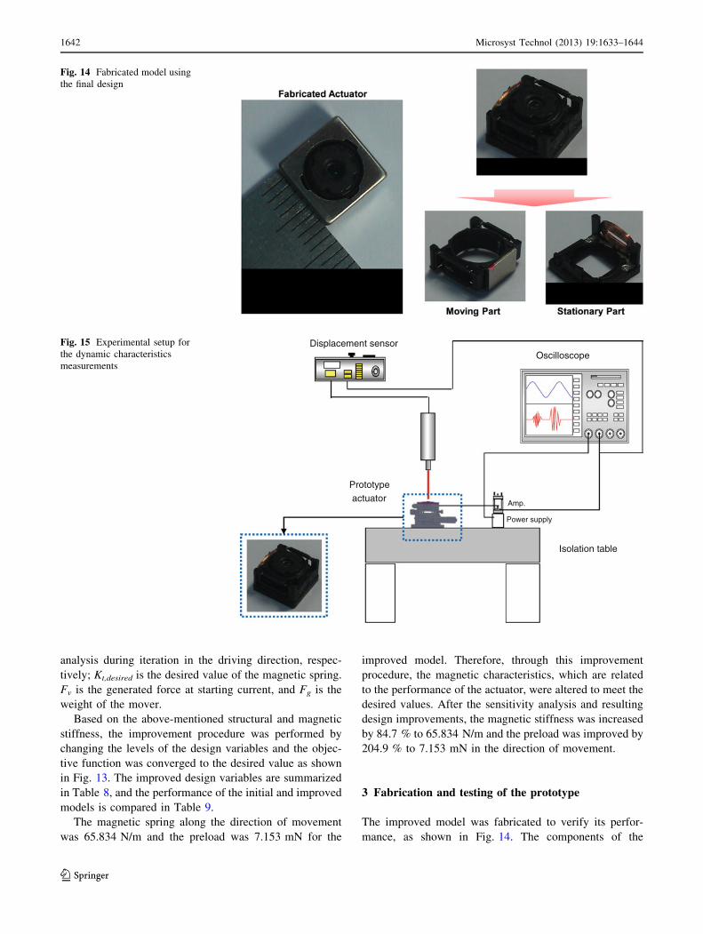
The improved model was fabricated to verify its perfor-
mance, as shown in Fig. 14. The components of the
Fig. 14 Fabricated model using
the final design
Displacement sensor
Amp.
Power supply
Oscilloscope
Isolation table
Prototype actuator
Fig. 15 Experimental setup for
the dynamic characteristics
measurements
1642 Microsyst Technol (2013) 19:1633–1644
123
structural and EM circuit parts were manufactured. The
lens holder was made of Hytrel 6356, the yoke was made of
sus430 material, and the magnet was made of Nd–Fe-B
48H. Figure 15 shows the experimental setup used for
dynamic tests of the prototype actuator, which had
dimensions of 8.5 9 8.5 9 5.1 mm. The experimental
setup was constructed using dSPACE, a displacement
sensor (Keyence, LC-2440), an operational amplifier, an
oscilloscope, and the fabricated prototype actuator.
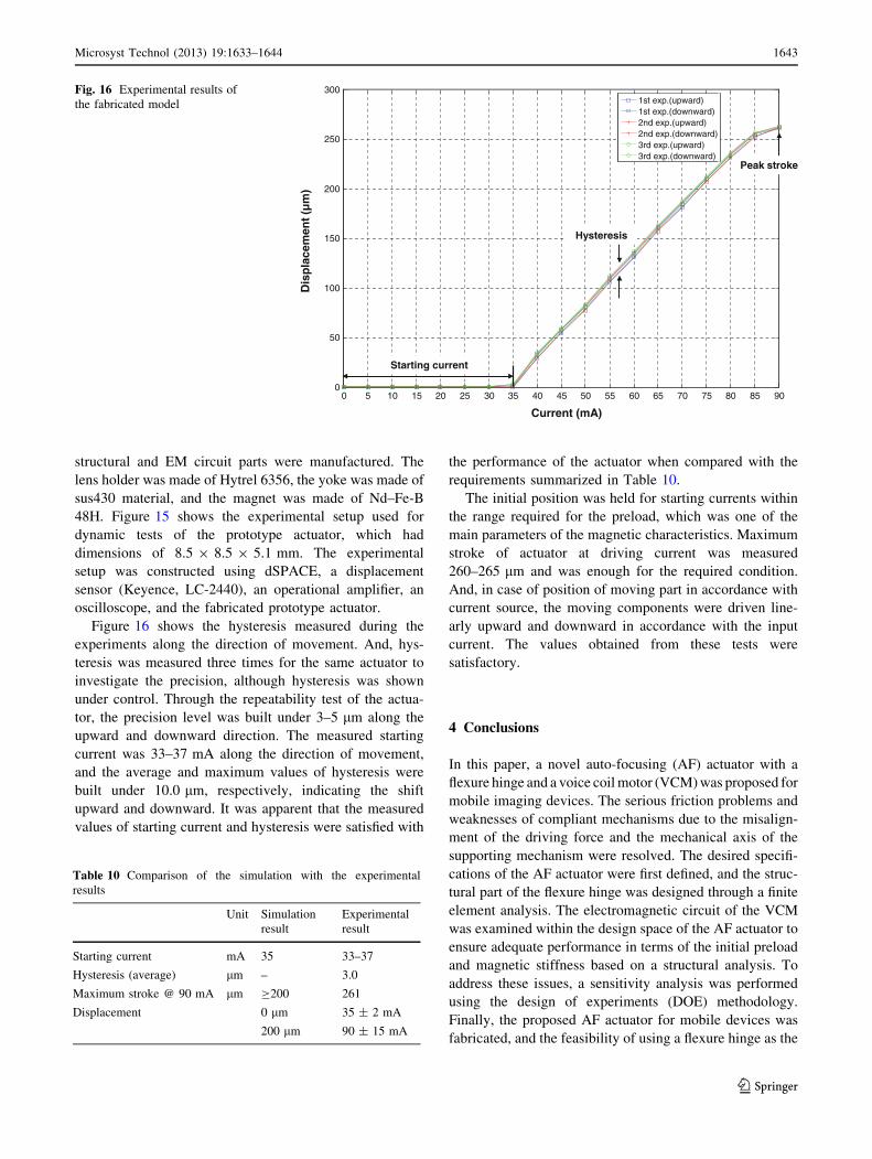
Figure 16 shows the hysteresis measured during the
experiments along the direction of movement. And, hys-
teresis was measured three times for the same actuator to
investigate the precision, although hysteresis was shown
under control. Through the repeatability test of the actua-
tor, the precision level was built under 3–5 lm along the
upward and downward direction. The measured starting
current was 33–37 mA along the direction of movement,
and the average and maximum values of hysteresis were
built under 10.0 lm, respectively, indicating the shift
upward and downward. It was apparent that the measured
values of starting current and hysteresis were satisfied with
the performance of the actuator when compared with the
requirements summarized in Table 10.
The initial position was held for starting currents within
the range required for the preload, which was one of the
main parameters of the magnetic characteristics. Maximum
stroke of actuator at driving current was measured
260–265 lm and was enough for the required condition.
And, in case of position of moving part in accordance with
current source, the moving components were driven line-
arly upward and downward in accordance with the input
current. The values obtained from these tests were
satisfactory.
4 Conclusions
In this paper, a novel auto-focusing (AF) actuator with a
flexure hinge and a voice coil motor (VCM) was proposed for
mobile imaging devices. The serious friction problems and
weaknesses of compliant mechanisms due to the misalign-
ment of the driving force and the mechanical axis of the
supporting mechanism were resolved. The desired specifi-
cations of the AF actuator were first defined, and the struc-
tural part of the flexure hinge was designed through a finite
element analysis. The electromagnetic circuit of the VCM
was examined within the design space of the AF actuator to
ensure adequate performance in terms of the initial preload
and magnetic stiffness based on a structural analysis. To
address these issues, a sensitivity analysis was performed
using the design of experiments (DOE) methodology.
Finally, the proposed AF actuator for mobile devices was
fabricated, and the feasibility of using a flexure hinge as the
0 5 10 15 20 25 30 35 40 45 50 55 60 65 70 75 80 85 900
50
100
150
200
250
3001st exp.(upward)1st exp.(downward)2nd exp.(upward)2nd exp.(downward)3rd exp.(upward)3rd exp.(downward)
Dis
pla
cem
ent (
µm
)
Current (mA)
Starting current
Hysteresis
Peak stroke
Fig. 16 Experimental results of
the fabricated model
Table 10 Comparison of the simulation with the experimental
results
Unit Simulation
result
Experimental
result
Starting current mA 35 33–37
Hysteresis (average) lm – 3.0
Maximum stroke @ 90 mA lm C200 261
Displacement 0 lm 35 ± 2 mA
200 lm 90 ± 15 mA
Microsyst Technol (2013) 19:1633–1644 1643
123
supporting mechanism with a VCM was experimentally
verified. The experimental results indicated that the pro-
posed AF actuator exhibited adequate performance with
respect to the design requirements for the actuator.‘
Acknowledgments The support of the MuTas Co., Ltd. is gratefully
acknowledged. This work was supported by the National Research
Foundation of Korea (NRF) grant funded by the Korea govern-
ment(MEST) (No. 2012-0001013).
References
Cheng DK (1994) Fundamentals of engineering electromagnetics, 1st
edn. Prentice Hall, New Jersey, pp 220–222
Guo S X, Sugimoto K, and Hata S (2000) Development of a macro/
micro mechanism for human scale teleoperating system. Inter-
national Symposium on Micromechatronics and Human Science,
Nagoya
Hao Xiuquing, Cai KY, Xu ZG, Peng XJ (2010) Design of flexible
hinge of micro-vibration platform based on three-translational
parallel mechanism. In: International conference on measuring
technology and mechatronics automation, pp 993–996. doi:
10.1109/ICMTMA
Jung SB (1994) Improvement of scanning accuracy of PZT Piezo-
electric actuators by feed-forward model-reference control.
J Precis Eng 14:49–55
Jung JK, Youm WS, Park KH (2009) Vibration reduction control of a
voice coil motor nano scanner. Int J Precis Eng Manuf
10(3):167–170
Jung JK, Youm WS, Park KH (2010) Vibration reduction control of a
voice coil motor-driven actuator for SPM applications. Int J Adv
Manuf Technol 46:923–930
Kim KH, Lee SY, Kim SK (2009) A mobile auto-focus actuator based
on a rotary VCM with the zero holding current. Opt Express
17:5891–5896
Kim C, Song MG, Park NC, Park YP, Park KS, Song DY (2011)
Design of a hybrid optical image stabilization actuator to
compensate for hand trembling. Microsyst Technol 17(5):
971–981
Kim C, Song MG, Kim YJ, Park NC, Park YP, Park KS (2012)
Design of a hybrid optical image stabilization actuator to
compensate for hand trembling. Microsyst Technol 18:
1323–1334
Li YM, Xu QS (2009) Design and optimization of an XYZ parallel
micromanupulator with flexure hinges. J Intell Robot Syst
55:377–402
Liu CS, Lin PD (2009) Miniaturized auto-focusing VCM actuator
with zero holding current. Opt Express 17:9754–9763
Shim JH, Cho HS (1999) A new macro/micro robotic probing system
for the in-circuit test of PCBs. Mechatronics 9(6):589–613
Song MG, Hur YJ, Park NC, Park YP, Park KS, Lim SC, Park JH
(2009) Development of small sized actuator for optical image
stabilization. IEEE Trans Magn 7:152–157
Song MG, Baek HW, Park NC, Park YP, Park KS, Lim SC (2010)
Development of small sized actuator with compliant mechanism
for optical image stabilization. IEEE Trans Magn 46(6):
2369–2371
Song MG, Park NC, Park KS, Park YP (2011) Design of a leaf spring
using a genetic algorithm. IEEE Trans Magn 47(3):590–593
Woo JH, Park NC, Park YP, Park KS, Oh YS, Kim KB (2010)
Development of asymmetric twin objective lens actuator using
integrated design method. Jpn J Appl Phys 49:08KA02
Yeom DH (2009) Optical image stabilizer for digital photographing
apparatus. IEEE Trans Consumer Electron 55(3):1028–1031
Yu HC, Liu TS (2007) Design of a slim optical image stabilization
actuator for mobile phone cameras. Phys Stat Sol (c) 4(12):
4647–4650
Zhang JH, Xiao CR, Yang XD (2006) Design of 2D flexible hinge
stage with multi-parameter. J Phys: Conf Ser 48:233–238
1644 Microsyst Technol (2013) 19:1633–1644
123