Embed Size (px)
DESCRIPTION
A lecture presented on the design of FRP components and all-composite FRP structures
Citation preview
Design of FRP-Profiles and All-FRP-Structures Fibre Composites FS09 A Schumacher 14102009
Design of FRP-Profiles and All-FRP-Structures
- Lecture Dr Ann Schumacher annschumacherempach
- Exercise Dr Andrin Herwig andrinherwigempach
ReferencesBank L ldquoComposites for Construction - Structural Design with FRP MaterialsrdquoJohn Wiley amp Sons Inc 2006 (Chapters 12 - 15)Fiberline ldquoFiberline Design Manualrdquo wwwfiberlinedk 2003Clarke JL (Ed) ldquoStructural Design of Polymer Composites - EUROCOMP Design Code and Handbookrdquo E amp FN Spon 1996
Design of FRP-Profiles and All-FRP-Structures
Design of FRP-Profiles and All-FRP-Structures Fibre Composites FS09 A Schumacher 14102009
Outline
Introduction(Prorsquos and conrsquos of FRP Examples)
Materials(Manufacturing process Materials Durability)
Design Concept(Concept Basic assumptions hellip)
Bending Beam(Timoshenko theory Stresses Deformations Buckling hellip)
Axial Members(Serviceability and ultimate limit states)
Connections(Bolted joints Glued joints)
Design of FRP-Profiles and All-FRP-Structures Fibre Composites FS09 A Schumacher 14102009
Introduction
Design of FRP-Profiles and All-FRP-Structures Fibre Composites FS09 A Schumacher 14102009
Introduction Prorsquos and conrsquos
ProrsquosHigh specific strength
Good in-plane mechanical properties
High fatigue and environmental resistance
Adjustable mechanical properties
Lightweight
Quick assembly erection
Low maintenance
Highly cost-effective (2-10 eurokg)
maxmaxl g
σρ
=sdot
1384 km
CFRP
64 km278 km
Steel S500GFRPMaterial
Design of FRP-Profiles and All-FRP-Structures Fibre Composites FS09 A Schumacher 14102009
Introduction Prorsquos and conrsquos
ConrsquosLightweight
Brittle
High initial costs
Low to moderate application temperature (-20 up to 80 degC)
Low fire resistance (sometimes with unhealthy gases)
Design of FRP-Profiles and All-FRP-Structures Fibre Composites FS09 A Schumacher 14102009
Introduction Common profiles
Structural profilesMost structural profiles produced in conventional profile shapes similar to metallic materials
Similarity in geom and properties however no standard geom mechanical and physical properties used by all manufacturers
Structural profiles Non-structural profiles
Design of FRP-Profiles and All-FRP-Structures Fibre Composites FS09 A Schumacher 14102009
Introduction Examples
Footbridges
Fiberline Bridge in Kolding DK
Span 40 mCost 05 mio CHFOnly Fiberline standard profiles used
httpwwwfiberlinecomgbcasestoriescase1837asp
Pontresina bridge Switzerland
Span 2 x 125 mWeight 33 tons (installation by helicopter)
httpwwwfiberlinecomgbcasestoriescase1830asp
Design of FRP-Profiles and All-FRP-Structures Fibre Composites FS09 A Schumacher 14102009
Introduction Examples
Footbridges
Composite pedestrian bridge in Lleida Spain
Span 38 mWidth 30 m
httpwwwfiberlinecomgbcasestoriescase2828asp
Design of FRP-Profiles and All-FRP-Structures Fibre Composites FS09 A Schumacher 14102009
Introduction Examples (ASSET Profile)
Road bridges
West Mill Bridge England
Span 10 mWidth 68 mLoad capacity 46 tons
httpwwwfiberlinecomgbcasestoriescase3903asp
Klipphausen Bridge Germany
Span 68 mWidth 60 mLoad capacity 40 tons
httpwwwfiberlinecomgbcasestoriescase6314asp
Design of FRP-Profiles and All-FRP-Structures Fibre Composites FS09 A Schumacher 14102009
Introduction Examples
Bridgedeck (Footbridges)Wuumlrenlos Switzerland Loopersteg Switzerland
Design of FRP-Profiles and All-FRP-Structures Fibre Composites FS09 A Schumacher 14102009
Introduction Examples
Buildings
Eyecatcher Building Basel Switzerland
Height 15 mStoreys 5
httpwwwfiberlinecomgbcasestoriescase1835asp
Project Maagtechnic
Design of FRP-Profiles and All-FRP-Structures Fibre Composites FS09 A Schumacher 14102009
Introduction Examples
Laboratory bridgeEmpa Laboratory Bridge Switzerland
Span 19 mWidth 16 mLoad capacity 15 tons
Design of FRP-Profiles and All-FRP-Structures Fibre Composites FS09 A Schumacher 14102009
Introduction Examples
Noise barrier SBB
Goumlschenen Switzerland
Project Maagtechnic
Design of FRP-Profiles and All-FRP-Structures Fibre Composites FS09 A Schumacher 14102009
Introduction Examples
Balconies
Switzerland
Project Maagtechnic
Design of FRP-Profiles and All-FRP-Structures Fibre Composites FS09 A Schumacher 14102009
Introduction Examples
RailingsOensingen Switzerland
Heineken brewery Switzerland
Design of FRP-Profiles and All-FRP-Structures Fibre Composites FS09 A Schumacher 14102009
Introduction Application
Applications where GFRP structures are competitive
Significant corrosion and chemical resistance is required(Food and chemical processing plants cooling towers offshore platforms hellip)
Electromagnetic transparency or electrical insulation is required
Light-weight is cost essential(fast deployment hellip)
Prestige and demonstration objects (eg Novartis Campus Entrance Building)
Photo Prof Th Keller EPFL
Design of FRP-Profiles and All-FRP-Structures Fibre Composites FS09 A Schumacher 14102009
Material
Design of FRP-Profiles and All-FRP-Structures Fibre Composites FS09 A Schumacher 14102009
Only pultruded GFRP profiles will be considered in this lecture
Production of profiles with constant cross-section along the length
High quality
Continuous longitudinal fiber bundles and filament mats
Pultrusion line
Material Pultrusion process
Design of FRP-Profiles and All-FRP-Structures Fibre Composites FS09 A Schumacher 14102009
Material Components
Pultruded profiles contain three primary componentsreinforcement
Matrix
Supplementaryconstituents
polyesterepoxyphenol
polymerisation agentsfillersadditives
Design of FRP-Profiles and All-FRP-Structures Fibre Composites FS09 A Schumacher 14102009
Material Shapes of pultruded profiles
Available Profiles on Stock
Length up to 12 m
Special cross-sections can be designed and ordered(several kilometres are necessary rarr special tools have to be designed)
Design of FRP-Profiles and All-FRP-Structures Fibre Composites FS09 A Schumacher 14102009
Material Durability
Various environmental and load conditions that affect durability of (G)FRPs in terms of strength stiffness fibermatrix interface integrity cracking
watersea waterchemical solutionsprolonged freezingthermal cycling (freeze-thaw)elevated temperature exposureUV radiationcreep and relaxationfatiguefirehellip
Design of FRP-Profiles and All-FRP-Structures Fibre Composites FS09 A Schumacher 14102009
Material Durability
Environmental reduction factor for different FRP systems and exposure conditions
070Aramidepoxy
050Glassepoxy(chemical plants)
085CarbonepoxyAgressive environ
075Aramidepoxyparking garages)
065Glassepoxy(bridges piers
085CarbonepoxyExterior exposure
085Aramidepoxy
075Glassepoxy
095CarbonepoxyInterior exposure
Environ reductionFiber resin typeExposure condition
Design of FRP-Profiles and All-FRP-Structures Fibre Composites FS09 A Schumacher 14102009
Material Durability
GFRP is more susceptible to degradation than CFRP by the following effects
alkaline effects (caution when GFRP in contact with concrete)acid effectssalt effectsfatigueUV radiation
Fire protection is a major (unsolved) issue for (G)FRP structural elements and components
Smoke generation and toxicity must be consideredStrength of GFRP is affected by fatigue loading(more than CFRP)
Design of FRP-Profiles and All-FRP-Structures Fibre Composites FS09 A Schumacher 14102009
Material Manufacturers
GFRP profiles available on stock
In Europe two companies pultrude FRP-Profiles
Fiberline Composites Denmarkwwwfiberlinecom
Fiberline Design Manual (wwwfiberlinedk)rarr helpful tool to design structures
(material properties geometries connections hellip)
Top Glass Italywwwtopglassit
Design of FRP-Profiles and All-FRP-Structures Fibre Composites FS09 A Schumacher 14102009
Material Manufacturers
GFRP profiles available on stock
In North America
Strongwell USAwwwstrongwellcom
Creative Pultrusions USAwwwcreativepultrusionscom
Bedford Reinforced Plastics USAwwwbedfordplasticscom
Design of FRP-Profiles and All-FRP-Structures Fibre Composites FS09 A Schumacher 14102009
Design Concept
Design of FRP-Profiles and All-FRP-Structures Fibre Composites FS09 A Schumacher 14102009
Design Concept Basic Assumptions
Definitions and directions
Design of FRP-Profiles and All-FRP-Structures Fibre Composites FS09 A Schumacher 14102009
Design Concept
Codes
Every manufacturer has its own profile design rarr No European Design Code is available (only EN13706 about testing and notation)
There exists European guidelines EUROCOMP 1996 Design CodeEUROCOMP 1996 Handbook
Fiberline Design Manual is based on Eurocomp 1996
Design concept (according to Eurocodes and Swisscodes)
Partial safety factors
Measured material parameters
Rules for bolted connections
Design of FRP-Profiles and All-FRP-Structures Fibre Composites FS09 A Schumacher 14102009
Design Concept
Concept of Limit State Design (According to Euro Codes and Swiss Codes)
Ultimate limit stress
Ed le Rd
Ed hellip Calculated stress (including load factors) hellip SIA260 261
Rd hellip Rated value of the resistance capability
where
Rk hellip the calculated resistance capability
kd mγ=
RR
Design of FRP-Profiles and All-FRP-Structures Fibre Composites FS09 A Schumacher 14102009
101020Production process
Operating temperature
111116Degree of postcuring
115115225Derivation of mat properties
FiberlineMinMaxDescriptionCoefficient
Design Concept
Reduction coefficient m m1 m2 m3 m4γ γ γ γ γ= sdot sdot sdot
m1γ
m2γ
m3γ
m4γ
mγ mγ
31312580
2510-20 +60
Long-term loadShort-term load
Operatingtemperature degC m4γ
Design of FRP-Profiles and All-FRP-Structures Fibre Composites FS09 A Schumacher 14102009
Design Concept
Serviceability limit states
Ed le Cd
Ed hellip the crucial action effect due to the load cases considered inthe investigated dimensioning situation Typically maximaldeflection response of the structure
Cd hellip corresponding serviceability limit SIA 261
Design of FRP-Profiles and All-FRP-Structures Fibre Composites FS09 A Schumacher 14102009
Design Concept Basic Assumptions
Material Properties stength values (Fiberline Profiles)
Design of FRP-Profiles and All-FRP-Structures Fibre Composites FS09 A Schumacher 14102009
Design Concept Basic Assumptions
Material Properties stiffness values (Fiberline Profiles)
Design of FRP-Profiles and All-FRP-Structures Fibre Composites FS09 A Schumacher 14102009
Design Concept Basic Assumptions
Typical data sheet of a profile (Fiberline I-Profile)
Design of FRP-Profiles and All-FRP-Structures Fibre Composites FS09 A Schumacher 14102009
Bending Beam
Design of FRP-Profiles and All-FRP-Structures Fibre Composites FS09 A Schumacher 14102009
Bending Beam Design of hellip
Calculate bending moments Md and shear forces Qd acting on the profile using the partial coefficient (SIA 260 261)
Ultimate limit state
Bending
Shear
Ak hellip relevant shear area
d max d max 0max
M MW Wy z b
mzy
fσ γ
⎛ ⎞⎜ ⎟⎜ ⎟⎜ ⎟⎜ ⎟⎝ ⎠
deg= + le
d maxmax
kyAy
m
Q fττ γ= le
Design of FRP-Profiles and All-FRP-Structures Fibre Composites FS09 A Schumacher 14102009
Bending Beam Design of hellip
Serviceability limit state
Deflection limit
hellip typically selected between 200 and 400given by SIA 261 or the building owner
hellip calculated including shear deformations
Vibrations
Light-weighted and lsquosoftrsquo structures are susceptible to vibrations (traffic wind the movement of people hellip)
max 1wL αlt
α
maxw
Design of FRP-Profiles and All-FRP-Structures Fibre Composites FS09 A Schumacher 14102009
Bending Beam Timoshenko Theory
Pultruded profiles have a low shear modulus rarr shear deformation must be taken into account
Several bending theories have been published for beams
Euler-Bernoulli theory (1702)
Timoshenko theory (1968)
Higher order beam theory
A simply supported beam with a symmetric cross-section is discussed
Design of FRP-Profiles and All-FRP-Structures Fibre Composites FS09 A Schumacher 14102009
Bending Beam Timoshenko Theory
Cross-sections planeand perpendicular
1 degree of freedom
w
Cross-sections plane butNOT perpendicular
2 degrees of freedom
w and ψ
Cross-sections do NOTremain plane
3+ degrees of freedom
w ψ and hellip
Design of FRP-Profiles and All-FRP-Structures Fibre Composites FS09 A Schumacher 14102009
Bending Beam Euler vs Timoshenko Theory
Kinematic relationships
( )( )
( )
2 0
x x
y
xx xx
yxxy
u y w xu w x
u y w xxuu
y x
ε
ε
=minus sdot=
part= =minus sdotpartpartpart= + =
part part
( )( )
( )
2 ( ) ( )
x
y
xx x
yxxy x
u y xu w x
u y xxuu x w xy x
ψ
ε ψ
ε ψ
=minus sdot=
part= =minus sdotpartpartpart= + =minus +
part part
Hookrsquos law
0degE and G 2x x xy xyσ ε τ ε= sdot = sdot
z0deg E Iz x xxQS
M y dydz wσ= minus sdot sdot = sdot sdotintint
( )
z0deg E I
z x xQS
y xQS
M y dydz
Q dydz w GA
σ ψ
κ τ ψ κ
= minus sdot sdot = sdot
= sdot = minus sdot sdot
intint
intint
Design of FRP-Profiles and All-FRP-Structures Fibre Composites FS09 A Schumacher 14102009
Bending Beam Euler vs Timoshenko Theory
Equilibrium
Solution for the simply supported beam (distributed load)
In a first approximation the deflections are calculated by direct integration of
z0deg
( ) E IxxM xw = sdot
( )( )z0deg
( ) E I 0x
x
xx x
xx x
q x w GAw GA
QM Q
ψ κψ ψ κ
minus minus sdot sdot
sdot + minus sdot sdot
=minus =
= =minus
Equilibrium on an infinitesimal beam element
Coupled second order differential equation
21 1( ) (0) 0 and ( ) 02 2
M x qLx qx w w L= minus = =
( )3 2 3
0deg z
( ) 224 E Iqxw x L Lx x= sdot minus +sdot sdot
2
0deg z
1 1 1E I 2 2xxw qLx qx⎛ ⎞= minus⎜ ⎟sdot ⎝ ⎠
(0) 0 and ( ) 0(0) 0 (0) 0 and ( ) 0 ( ) 0 x x
w w LM M L Lψ ψ
= == rarr = = rarr =
Functions4 3 2
1 2 3 4 53 2
1 2 3 4
( )
( )
w x A x A x A x A x A
x B x B x B x Bψ
= + + + +
= + + +
Design of FRP-Profiles and All-FRP-Structures Fibre Composites FS09 A Schumacher 14102009
Put in and solve for the coefficients rarr
Bending Beam Euler vs Timoshenko Theory
Use the boundary conditions and the second differential eq to calculate A1 ndash A5
( )0deg z E I 0xx xw GAψ ψ κsdot + minus sdot sdot =
1 01 1 3 3
2 02 2 4 4
24 E I4 2GA
6 E I3 GA
z
z
AB A B A
AB A B A
κ
κ
deg
deg
sdot= minus = minus minus
sdotsdot
= minus = minus minussdot
( ) ( )( )2 2
0
( )2 GA 24 E Iz
qx L x L Lx xqx L xw x
κ deg
minus + minusminus= +
sdot sdot sdot
Deflection at midspan
4
0
52 384 E Iz
qLLw⎛ ⎞⎜ ⎟⎝ ⎠
deg
sdot= sdot4 2
0
52 384 E I 8 GAz
qL q LLw κ⎛ ⎞ +⎜ ⎟⎝ ⎠
deg
sdot sdot= sdot sdot sdot
Design of FRP-Profiles and All-FRP-Structures Fibre Composites FS09 A Schumacher 14102009
General expression for the total beam deflection as a sum of the deflection due to bending and shear
GAxf
IExfxwz sdot+=
deg κ)()()( 2
0
1
Cantilever beam
Simply supported
Concentrated load (P)
Uniformly distr load (q)
Concentrated load (P)
Uniformly distr load (q)
Beam )( max1 wf
3845 4qLsdot
48
3PL
8
4qL
3
3PL
)( max1 wf
8
2qL
4PL
2
2qL
PL
)( maxwx
2L
2L
L
L
Bending Beam Euler vs Timoshenko Theory
Design of FRP-Profiles and All-FRP-Structures Fibre Composites FS09 A Schumacher 14102009
Bending Beam Euler vs Timoshenko Theory
Example influence of the shear deformation
Profile 300 x 150 mm I-beam
Load uniformly distributed
General rule of thumbfor GFRP beams withspandepth gt 25 sheardeformation can beignored
Design of FRP-Profiles and All-FRP-Structures Fibre Composites FS09 A Schumacher 14102009
Bending Beam Example
Choose an appropriate Profile for the following specifications
1 Deflections and loading
=
=
==
1300 rarr wmax=001 mwmaxL
10 kNmqdser
13 kNmqduls
30 mL
max
4 2
0
5384 E I 8 GA
d ser d serz
q L q Lw κ+
deg
sdot sdot= sdot sdot sdot
2
maxz8 2 I
d ulsq L hσ sdot= sdot
maxky
12 Ad ulsq L
τ sdot=
Design of FRP-Profiles and All-FRP-Structures Fibre Composites FS09 A Schumacher 14102009
Bending Beam Example
2 Find a profile with sufficient bending stiffness
Shear deformations are neglected in a first step
rarr from specification table choose I 240x120x12 rarr
3 Check the bending and shear stresses
6 24
0 max
1054 10 Nm5
E I 384d ser
zq Lwdeg = sdot
sdotsdotge
6 20 1369 10 NmE Izdeg = sdot
2
maxz
358 MPa8 2 Id ulsq L hσ sdot= =sdot
max
ky
1 71 MPa2 Ad ulsq L
τ sdot= =
0 185 MPab df degle =
20 MPadfτle =
Design of FRP-Profiles and All-FRP-Structures Fibre Composites FS09 A Schumacher 14102009
Bending Beam Example
m10398384
5 32
0
4
maxminus
deg
sdot=sdotsdotsdot
+sdot
sdot=
GALq
IELq
w serd
z
serd
κ
4 Check deflection (including shear deformation)
5 Remarks
The design of GFRP-profiles is mostly driven by serviceability criteria
Start the design iteration procedure using the maximal deflection criterion
max 001 mwle =
m10198384
5 32
0
4
maxminus
deg
sdot=sdot
sdot+
sdotsdot
=web
serd
z
serd
GALq
IELq
w
(77 mm) (16 mm)
Design of FRP-Profiles and All-FRP-Structures Fibre Composites FS09 A Schumacher 14102009
Bending Beam Stability problems
Lateral-torsional bucklingFlange (compressive) displace laterally to the transverse load direction
Torsional stiffness is too low (especially for open section profiles)
Theoretical calculations or design measuresrarr see eg LP Kollaacuter 2003
Mechanics of composite structuresExample
Compressive flanges are kept in place by connection to the bridge deck
Design of FRP-Profiles and All-FRP-Structures Fibre Composites FS09 A Schumacher 14102009
Bending Beam Stability problems
Flange (compressive) displaces in the direction of the transverse load
Low bending stiffness perpendicular to the pultrusion direction
Weak fiber mats
Local buckling of walls due to in-plane compression
Local buckling of walls due to in-plane shear
Web crushing and web buckling in transverse direction
Design of FRP-Profiles and All-FRP-Structures Fibre Composites FS09 A Schumacher 14102009
Axial Members
Design of FRP-Profiles and All-FRP-Structures Fibre Composites FS09 A Schumacher 14102009
Axial Members Tension
Ultimate limit state under axial tension Nd
Serviceability limit state
Remark The critical aspect of axial members in tension are neither the serviceability nor the ultimate limit state Critical is the load transfer to the GFRP profile
0NdA
tm
fγ
degle
0deg
N LE Axδ sdot= sdot
Design of FRP-Profiles and All-FRP-Structures Fibre Composites FS09 A Schumacher 14102009
Axial Members Compression
Ultimate limit state under axial compression Nd
hellip maximal compressive load
hellip Euler load
hellip Buckling length for columns
hellip coefficient for Youngrsquos modulus = 13
cc
Euler
FNd F1 N
le+
c0degC
A fF
mγsdot
=
20
Euler 2
Nm E k
E IL
πγ
degsdot sdot=
sdot
kL
m Eγ
Design of FRP-Profiles and All-FRP-Structures Fibre Composites FS09 A Schumacher 14102009
Axial Members Compression
The influence of shear deformation should be considered but in the most cases the influence will be small (less than 5)
Local buckling should be considered for short columns
For more information on the various buckling modes and effects rarr see LP Kollaacuter 2003 Mechanics of composite structures
Global buckling Local buckling
Design of FRP-Profiles and All-FRP-Structures Fibre Composites FS09 A Schumacher 14102009
Connections
Design of FRP-Profiles and All-FRP-Structures Fibre Composites FS09 A Schumacher 14102009
Connections Introduction
Design of FRP-Profiles and All-FRP-Structures Fibre Composites FS09 A Schumacher 14102009
Connections Introduction
(from Eurocomp Design Code 1996)
Design of FRP-Profiles and All-FRP-Structures Fibre Composites FS09 A Schumacher 14102009
Connections Bolted joints
Bolts = Stress concentration in the profile and the bolt
It is necessary to ensure that the bolts and the profilecan withstand this concentrated local stress compression
It is necessary to ensure that the region surroundinga group of bolts will not be torn out of the profile
Basic failure modesin bolted shearconnections
bolt shear failure
Design of FRP-Profiles and All-FRP-Structures Fibre Composites FS09 A Schumacher 14102009
Connections Bolted joints
The design procedure is comparable to the one for steel connections but since there exist no standard GFRP material rarr each manufacturer has its own design rules for bolted joints
IMPORTANT REMARKS
The direction of pultrusion and the direction of the force is RELEVANT(anisotropic material)
Use stainless or galvanised steel
Do not cut threads in the composite material
Use screws with shafts
Design of FRP-Profiles and All-FRP-Structures Fibre Composites FS09 A Schumacher 14102009
Calculation of load bearing capacity of bolts
Shear in longitudinal direction (0deg)
Shear in transverse direction (90deg)
Tensile force
Minimum distances
Connections Bolted joints (Fiberline recommendations)
Design of FRP-Profiles and All-FRP-Structures Fibre Composites FS09 A Schumacher 14102009
Joint capacity tables available for shear and tension
m
150 MPa( 13)B d
d tP γsdot sdot=
=
Shear in longitudinal direction 0deg
m
70 MPa( 13)B d
d tP γsdot sdot=
=
Shear in transverse direction 90deg
Connections Bolted joints (Fiberline recommendations)
Design of FRP-Profiles and All-FRP-Structures Fibre Composites FS09 A Schumacher 14102009
Bolted connection in shear eg shear in longitudinal direction
Connections Bolted joints (Fiberline recommendations)
γmPBolt le dt720 MPaγmPBolt le dt240 MPa
γmPBolt le dt240 MPa γmPBolt le dt240 MPaγmPBolt le dt150 MPa
Design of FRP-Profiles and All-FRP-Structures Fibre Composites FS09 A Schumacher 14102009
Bolted connections in tension
Static conditions
Bolt Tearing of bolt in threaded cross-section
Laminate Shear fracture at rim of washer
Geometry and strength
Diameter of washer2d
Tensile strength of bolt hellipfyk
Shear strength of laminatehellipfτ
Thickness of laminatet
Stress area of the boltAs
Diameter of the boltd
s ykd m
A fP γ
sdotle
2d m
d t fP τπγ
sdot sdot sdot sdotle
Connections Bolted joints (Fiberline recommendations)
Design of FRP-Profiles and All-FRP-Structures Fibre Composites FS09 A Schumacher 14102009
Connections Bonded joints
Using an adhesive agent for joining profiles can have advantages
Easy to use easy to make aesthetic joints
Typically more rigid than bolted joints
Glued joints subjected to dynamic loads are good
But be careful hellipAdhesive agents have properties that depend on time temperature humidity hellip
Failure in glued joints takes place suddenly (brittle behaviour)
The load-bearing capacity is not proportional to the area which is glued
The design of bonded joints may be based onAnalytical models for plate-to-plate connections (see Eurocomp 1996 Design Code)
Design guidelines supplemented by testing
Finite element analysis
Design of FRP-Profiles and All-FRP-Structures Fibre Composites FS09 A Schumacher 14102009
Connections Bonded joints
A bonded joint has the following three primary failure modes
adhesive failure
cohesive failure of adhesive
cohesive failure of adherend
The design of any bonded joint shall satisfy the following conditions
allowable shear stress in the adhesive is not exceeded
allowable tensile (peel) stress in the adhesive is not exceeded
allowable through-thickness tensile stress of the adhesive is not exceeded
allowable in-plane shear stress of the adherend should not be exceeded
The calculation of the stresses has to be done very carefully Often calculations are supplemented by testing
Design of FRP-Profiles and All-FRP-Structures Fibre Composites FS09 A Schumacher 14102009
Connections Bonded joints
Different types of bonded joint configurations
Research on bonded joints for structuralapplications
Design of FRP-Profiles and All-FRP-Structures Fibre Composites FS09 A Schumacher 14102009
Connections Other joints
Brackets for assembly (Fiberline)
Custom pultruded connections
Design of FRP-Profiles and All-FRP-Structures Fibre Composites FS09 A Schumacher 14102009
GFRP Some final remarks
Perpendicular to the direction of pultrusion the material is WEAK and SOFTrarr avoid such loadings if possible
In order to use pultruded GFRP-profiles economically the design must be done in a clever way eg for bridges the railings should be used as part of the load-bearing structure
GFRP structures are very light rarr vibration problems may occur
Design of FRP-Profiles and All-FRP-Structures Fibre Composites FS09 A Schumacher 14102009
Outline
Introduction(Prorsquos and conrsquos of FRP Examples)
Materials(Manufacturing process Materials Durability)
Design Concept(Concept Basic assumptions hellip)
Bending Beam(Timoshenko theory Stresses Deformations Buckling hellip)
Axial Members(Serviceability and ultimate limit states)
Connections(Bolted joints Glued joints)
Design of FRP-Profiles and All-FRP-Structures Fibre Composites FS09 A Schumacher 14102009
Introduction
Design of FRP-Profiles and All-FRP-Structures Fibre Composites FS09 A Schumacher 14102009
Introduction Prorsquos and conrsquos
ProrsquosHigh specific strength
Good in-plane mechanical properties
High fatigue and environmental resistance
Adjustable mechanical properties
Lightweight
Quick assembly erection
Low maintenance
Highly cost-effective (2-10 eurokg)
maxmaxl g
σρ
=sdot
1384 km
CFRP
64 km278 km
Steel S500GFRPMaterial
Design of FRP-Profiles and All-FRP-Structures Fibre Composites FS09 A Schumacher 14102009
Introduction Prorsquos and conrsquos
ConrsquosLightweight
Brittle
High initial costs
Low to moderate application temperature (-20 up to 80 degC)
Low fire resistance (sometimes with unhealthy gases)
Design of FRP-Profiles and All-FRP-Structures Fibre Composites FS09 A Schumacher 14102009
Introduction Common profiles
Structural profilesMost structural profiles produced in conventional profile shapes similar to metallic materials
Similarity in geom and properties however no standard geom mechanical and physical properties used by all manufacturers
Structural profiles Non-structural profiles
Design of FRP-Profiles and All-FRP-Structures Fibre Composites FS09 A Schumacher 14102009
Introduction Examples
Footbridges
Fiberline Bridge in Kolding DK
Span 40 mCost 05 mio CHFOnly Fiberline standard profiles used
httpwwwfiberlinecomgbcasestoriescase1837asp
Pontresina bridge Switzerland
Span 2 x 125 mWeight 33 tons (installation by helicopter)
httpwwwfiberlinecomgbcasestoriescase1830asp
Design of FRP-Profiles and All-FRP-Structures Fibre Composites FS09 A Schumacher 14102009
Introduction Examples
Footbridges
Composite pedestrian bridge in Lleida Spain
Span 38 mWidth 30 m
httpwwwfiberlinecomgbcasestoriescase2828asp
Design of FRP-Profiles and All-FRP-Structures Fibre Composites FS09 A Schumacher 14102009
Introduction Examples (ASSET Profile)
Road bridges
West Mill Bridge England
Span 10 mWidth 68 mLoad capacity 46 tons
httpwwwfiberlinecomgbcasestoriescase3903asp
Klipphausen Bridge Germany
Span 68 mWidth 60 mLoad capacity 40 tons
httpwwwfiberlinecomgbcasestoriescase6314asp
Design of FRP-Profiles and All-FRP-Structures Fibre Composites FS09 A Schumacher 14102009
Introduction Examples
Bridgedeck (Footbridges)Wuumlrenlos Switzerland Loopersteg Switzerland
Design of FRP-Profiles and All-FRP-Structures Fibre Composites FS09 A Schumacher 14102009
Introduction Examples
Buildings
Eyecatcher Building Basel Switzerland
Height 15 mStoreys 5
httpwwwfiberlinecomgbcasestoriescase1835asp
Project Maagtechnic
Design of FRP-Profiles and All-FRP-Structures Fibre Composites FS09 A Schumacher 14102009
Introduction Examples
Laboratory bridgeEmpa Laboratory Bridge Switzerland
Span 19 mWidth 16 mLoad capacity 15 tons
Design of FRP-Profiles and All-FRP-Structures Fibre Composites FS09 A Schumacher 14102009
Introduction Examples
Noise barrier SBB
Goumlschenen Switzerland
Project Maagtechnic
Design of FRP-Profiles and All-FRP-Structures Fibre Composites FS09 A Schumacher 14102009
Introduction Examples
Balconies
Switzerland
Project Maagtechnic
Design of FRP-Profiles and All-FRP-Structures Fibre Composites FS09 A Schumacher 14102009
Introduction Examples
RailingsOensingen Switzerland
Heineken brewery Switzerland
Design of FRP-Profiles and All-FRP-Structures Fibre Composites FS09 A Schumacher 14102009
Introduction Application
Applications where GFRP structures are competitive
Significant corrosion and chemical resistance is required(Food and chemical processing plants cooling towers offshore platforms hellip)
Electromagnetic transparency or electrical insulation is required
Light-weight is cost essential(fast deployment hellip)
Prestige and demonstration objects (eg Novartis Campus Entrance Building)
Photo Prof Th Keller EPFL
Design of FRP-Profiles and All-FRP-Structures Fibre Composites FS09 A Schumacher 14102009
Material
Design of FRP-Profiles and All-FRP-Structures Fibre Composites FS09 A Schumacher 14102009
Only pultruded GFRP profiles will be considered in this lecture
Production of profiles with constant cross-section along the length
High quality
Continuous longitudinal fiber bundles and filament mats
Pultrusion line
Material Pultrusion process
Design of FRP-Profiles and All-FRP-Structures Fibre Composites FS09 A Schumacher 14102009
Material Components
Pultruded profiles contain three primary componentsreinforcement
Matrix
Supplementaryconstituents
polyesterepoxyphenol
polymerisation agentsfillersadditives
Design of FRP-Profiles and All-FRP-Structures Fibre Composites FS09 A Schumacher 14102009
Material Shapes of pultruded profiles
Available Profiles on Stock
Length up to 12 m
Special cross-sections can be designed and ordered(several kilometres are necessary rarr special tools have to be designed)
Design of FRP-Profiles and All-FRP-Structures Fibre Composites FS09 A Schumacher 14102009
Material Durability
Various environmental and load conditions that affect durability of (G)FRPs in terms of strength stiffness fibermatrix interface integrity cracking
watersea waterchemical solutionsprolonged freezingthermal cycling (freeze-thaw)elevated temperature exposureUV radiationcreep and relaxationfatiguefirehellip
Design of FRP-Profiles and All-FRP-Structures Fibre Composites FS09 A Schumacher 14102009
Material Durability
Environmental reduction factor for different FRP systems and exposure conditions
070Aramidepoxy
050Glassepoxy(chemical plants)
085CarbonepoxyAgressive environ
075Aramidepoxyparking garages)
065Glassepoxy(bridges piers
085CarbonepoxyExterior exposure
085Aramidepoxy
075Glassepoxy
095CarbonepoxyInterior exposure
Environ reductionFiber resin typeExposure condition
Design of FRP-Profiles and All-FRP-Structures Fibre Composites FS09 A Schumacher 14102009
Material Durability
GFRP is more susceptible to degradation than CFRP by the following effects
alkaline effects (caution when GFRP in contact with concrete)acid effectssalt effectsfatigueUV radiation
Fire protection is a major (unsolved) issue for (G)FRP structural elements and components
Smoke generation and toxicity must be consideredStrength of GFRP is affected by fatigue loading(more than CFRP)
Design of FRP-Profiles and All-FRP-Structures Fibre Composites FS09 A Schumacher 14102009
Material Manufacturers
GFRP profiles available on stock
In Europe two companies pultrude FRP-Profiles
Fiberline Composites Denmarkwwwfiberlinecom
Fiberline Design Manual (wwwfiberlinedk)rarr helpful tool to design structures
(material properties geometries connections hellip)
Top Glass Italywwwtopglassit
Design of FRP-Profiles and All-FRP-Structures Fibre Composites FS09 A Schumacher 14102009
Material Manufacturers
GFRP profiles available on stock
In North America
Strongwell USAwwwstrongwellcom
Creative Pultrusions USAwwwcreativepultrusionscom
Bedford Reinforced Plastics USAwwwbedfordplasticscom
Design of FRP-Profiles and All-FRP-Structures Fibre Composites FS09 A Schumacher 14102009
Design Concept
Design of FRP-Profiles and All-FRP-Structures Fibre Composites FS09 A Schumacher 14102009
Design Concept Basic Assumptions
Definitions and directions
Design of FRP-Profiles and All-FRP-Structures Fibre Composites FS09 A Schumacher 14102009
Design Concept
Codes
Every manufacturer has its own profile design rarr No European Design Code is available (only EN13706 about testing and notation)
There exists European guidelines EUROCOMP 1996 Design CodeEUROCOMP 1996 Handbook
Fiberline Design Manual is based on Eurocomp 1996
Design concept (according to Eurocodes and Swisscodes)
Partial safety factors
Measured material parameters
Rules for bolted connections
Design of FRP-Profiles and All-FRP-Structures Fibre Composites FS09 A Schumacher 14102009
Design Concept
Concept of Limit State Design (According to Euro Codes and Swiss Codes)
Ultimate limit stress
Ed le Rd
Ed hellip Calculated stress (including load factors) hellip SIA260 261
Rd hellip Rated value of the resistance capability
where
Rk hellip the calculated resistance capability
kd mγ=
RR
Design of FRP-Profiles and All-FRP-Structures Fibre Composites FS09 A Schumacher 14102009
101020Production process
Operating temperature
111116Degree of postcuring
115115225Derivation of mat properties
FiberlineMinMaxDescriptionCoefficient
Design Concept
Reduction coefficient m m1 m2 m3 m4γ γ γ γ γ= sdot sdot sdot
m1γ
m2γ
m3γ
m4γ
mγ mγ
31312580
2510-20 +60
Long-term loadShort-term load
Operatingtemperature degC m4γ
Design of FRP-Profiles and All-FRP-Structures Fibre Composites FS09 A Schumacher 14102009
Design Concept
Serviceability limit states
Ed le Cd
Ed hellip the crucial action effect due to the load cases considered inthe investigated dimensioning situation Typically maximaldeflection response of the structure
Cd hellip corresponding serviceability limit SIA 261
Design of FRP-Profiles and All-FRP-Structures Fibre Composites FS09 A Schumacher 14102009
Design Concept Basic Assumptions
Material Properties stength values (Fiberline Profiles)
Design of FRP-Profiles and All-FRP-Structures Fibre Composites FS09 A Schumacher 14102009
Design Concept Basic Assumptions
Material Properties stiffness values (Fiberline Profiles)
Design of FRP-Profiles and All-FRP-Structures Fibre Composites FS09 A Schumacher 14102009
Design Concept Basic Assumptions
Typical data sheet of a profile (Fiberline I-Profile)
Design of FRP-Profiles and All-FRP-Structures Fibre Composites FS09 A Schumacher 14102009
Bending Beam
Design of FRP-Profiles and All-FRP-Structures Fibre Composites FS09 A Schumacher 14102009
Bending Beam Design of hellip
Calculate bending moments Md and shear forces Qd acting on the profile using the partial coefficient (SIA 260 261)
Ultimate limit state
Bending
Shear
Ak hellip relevant shear area
d max d max 0max
M MW Wy z b
mzy
fσ γ
⎛ ⎞⎜ ⎟⎜ ⎟⎜ ⎟⎜ ⎟⎝ ⎠
deg= + le
d maxmax
kyAy
m
Q fττ γ= le
Design of FRP-Profiles and All-FRP-Structures Fibre Composites FS09 A Schumacher 14102009
Bending Beam Design of hellip
Serviceability limit state
Deflection limit
hellip typically selected between 200 and 400given by SIA 261 or the building owner
hellip calculated including shear deformations
Vibrations
Light-weighted and lsquosoftrsquo structures are susceptible to vibrations (traffic wind the movement of people hellip)
max 1wL αlt
α
maxw
Design of FRP-Profiles and All-FRP-Structures Fibre Composites FS09 A Schumacher 14102009
Bending Beam Timoshenko Theory
Pultruded profiles have a low shear modulus rarr shear deformation must be taken into account
Several bending theories have been published for beams
Euler-Bernoulli theory (1702)
Timoshenko theory (1968)
Higher order beam theory
A simply supported beam with a symmetric cross-section is discussed
Design of FRP-Profiles and All-FRP-Structures Fibre Composites FS09 A Schumacher 14102009
Bending Beam Timoshenko Theory
Cross-sections planeand perpendicular
1 degree of freedom
w
Cross-sections plane butNOT perpendicular
2 degrees of freedom
w and ψ
Cross-sections do NOTremain plane
3+ degrees of freedom
w ψ and hellip
Design of FRP-Profiles and All-FRP-Structures Fibre Composites FS09 A Schumacher 14102009
Bending Beam Euler vs Timoshenko Theory
Kinematic relationships
( )( )
( )
2 0
x x
y
xx xx
yxxy
u y w xu w x
u y w xxuu
y x
ε
ε
=minus sdot=
part= =minus sdotpartpartpart= + =
part part
( )( )
( )
2 ( ) ( )
x
y
xx x
yxxy x
u y xu w x
u y xxuu x w xy x
ψ
ε ψ
ε ψ
=minus sdot=
part= =minus sdotpartpartpart= + =minus +
part part
Hookrsquos law
0degE and G 2x x xy xyσ ε τ ε= sdot = sdot
z0deg E Iz x xxQS
M y dydz wσ= minus sdot sdot = sdot sdotintint
( )
z0deg E I
z x xQS
y xQS
M y dydz
Q dydz w GA
σ ψ
κ τ ψ κ
= minus sdot sdot = sdot
= sdot = minus sdot sdot
intint
intint
Design of FRP-Profiles and All-FRP-Structures Fibre Composites FS09 A Schumacher 14102009
Bending Beam Euler vs Timoshenko Theory
Equilibrium
Solution for the simply supported beam (distributed load)
In a first approximation the deflections are calculated by direct integration of
z0deg
( ) E IxxM xw = sdot
( )( )z0deg
( ) E I 0x
x
xx x
xx x
q x w GAw GA
QM Q
ψ κψ ψ κ
minus minus sdot sdot
sdot + minus sdot sdot
=minus =
= =minus
Equilibrium on an infinitesimal beam element
Coupled second order differential equation
21 1( ) (0) 0 and ( ) 02 2
M x qLx qx w w L= minus = =
( )3 2 3
0deg z
( ) 224 E Iqxw x L Lx x= sdot minus +sdot sdot
2
0deg z
1 1 1E I 2 2xxw qLx qx⎛ ⎞= minus⎜ ⎟sdot ⎝ ⎠
(0) 0 and ( ) 0(0) 0 (0) 0 and ( ) 0 ( ) 0 x x
w w LM M L Lψ ψ
= == rarr = = rarr =
Functions4 3 2
1 2 3 4 53 2
1 2 3 4
( )
( )
w x A x A x A x A x A
x B x B x B x Bψ
= + + + +
= + + +
Design of FRP-Profiles and All-FRP-Structures Fibre Composites FS09 A Schumacher 14102009
Put in and solve for the coefficients rarr
Bending Beam Euler vs Timoshenko Theory
Use the boundary conditions and the second differential eq to calculate A1 ndash A5
( )0deg z E I 0xx xw GAψ ψ κsdot + minus sdot sdot =
1 01 1 3 3
2 02 2 4 4
24 E I4 2GA
6 E I3 GA
z
z
AB A B A
AB A B A
κ
κ
deg
deg
sdot= minus = minus minus
sdotsdot
= minus = minus minussdot
( ) ( )( )2 2
0
( )2 GA 24 E Iz
qx L x L Lx xqx L xw x
κ deg
minus + minusminus= +
sdot sdot sdot
Deflection at midspan
4
0
52 384 E Iz
qLLw⎛ ⎞⎜ ⎟⎝ ⎠
deg
sdot= sdot4 2
0
52 384 E I 8 GAz
qL q LLw κ⎛ ⎞ +⎜ ⎟⎝ ⎠
deg
sdot sdot= sdot sdot sdot
Design of FRP-Profiles and All-FRP-Structures Fibre Composites FS09 A Schumacher 14102009
General expression for the total beam deflection as a sum of the deflection due to bending and shear
GAxf
IExfxwz sdot+=
deg κ)()()( 2
0
1
Cantilever beam
Simply supported
Concentrated load (P)
Uniformly distr load (q)
Concentrated load (P)
Uniformly distr load (q)
Beam )( max1 wf
3845 4qLsdot
48
3PL
8
4qL
3
3PL
)( max1 wf
8
2qL
4PL
2
2qL
PL
)( maxwx
2L
2L
L
L
Bending Beam Euler vs Timoshenko Theory
Design of FRP-Profiles and All-FRP-Structures Fibre Composites FS09 A Schumacher 14102009
Bending Beam Euler vs Timoshenko Theory
Example influence of the shear deformation
Profile 300 x 150 mm I-beam
Load uniformly distributed
General rule of thumbfor GFRP beams withspandepth gt 25 sheardeformation can beignored
Design of FRP-Profiles and All-FRP-Structures Fibre Composites FS09 A Schumacher 14102009
Bending Beam Example
Choose an appropriate Profile for the following specifications
1 Deflections and loading
=
=
==
1300 rarr wmax=001 mwmaxL
10 kNmqdser
13 kNmqduls
30 mL
max
4 2
0
5384 E I 8 GA
d ser d serz
q L q Lw κ+
deg
sdot sdot= sdot sdot sdot
2
maxz8 2 I
d ulsq L hσ sdot= sdot
maxky
12 Ad ulsq L
τ sdot=
Design of FRP-Profiles and All-FRP-Structures Fibre Composites FS09 A Schumacher 14102009
Bending Beam Example
2 Find a profile with sufficient bending stiffness
Shear deformations are neglected in a first step
rarr from specification table choose I 240x120x12 rarr
3 Check the bending and shear stresses
6 24
0 max
1054 10 Nm5
E I 384d ser
zq Lwdeg = sdot
sdotsdotge
6 20 1369 10 NmE Izdeg = sdot
2
maxz
358 MPa8 2 Id ulsq L hσ sdot= =sdot
max
ky
1 71 MPa2 Ad ulsq L
τ sdot= =
0 185 MPab df degle =
20 MPadfτle =
Design of FRP-Profiles and All-FRP-Structures Fibre Composites FS09 A Schumacher 14102009
Bending Beam Example
m10398384
5 32
0
4
maxminus
deg
sdot=sdotsdotsdot
+sdot
sdot=
GALq
IELq
w serd
z
serd
κ
4 Check deflection (including shear deformation)
5 Remarks
The design of GFRP-profiles is mostly driven by serviceability criteria
Start the design iteration procedure using the maximal deflection criterion
max 001 mwle =
m10198384
5 32
0
4
maxminus
deg
sdot=sdot
sdot+
sdotsdot
=web
serd
z
serd
GALq
IELq
w
(77 mm) (16 mm)
Design of FRP-Profiles and All-FRP-Structures Fibre Composites FS09 A Schumacher 14102009
Bending Beam Stability problems
Lateral-torsional bucklingFlange (compressive) displace laterally to the transverse load direction
Torsional stiffness is too low (especially for open section profiles)
Theoretical calculations or design measuresrarr see eg LP Kollaacuter 2003
Mechanics of composite structuresExample
Compressive flanges are kept in place by connection to the bridge deck
Design of FRP-Profiles and All-FRP-Structures Fibre Composites FS09 A Schumacher 14102009
Bending Beam Stability problems
Flange (compressive) displaces in the direction of the transverse load
Low bending stiffness perpendicular to the pultrusion direction
Weak fiber mats
Local buckling of walls due to in-plane compression
Local buckling of walls due to in-plane shear
Web crushing and web buckling in transverse direction
Design of FRP-Profiles and All-FRP-Structures Fibre Composites FS09 A Schumacher 14102009
Axial Members
Design of FRP-Profiles and All-FRP-Structures Fibre Composites FS09 A Schumacher 14102009
Axial Members Tension
Ultimate limit state under axial tension Nd
Serviceability limit state
Remark The critical aspect of axial members in tension are neither the serviceability nor the ultimate limit state Critical is the load transfer to the GFRP profile
0NdA
tm
fγ
degle
0deg
N LE Axδ sdot= sdot
Design of FRP-Profiles and All-FRP-Structures Fibre Composites FS09 A Schumacher 14102009
Axial Members Compression
Ultimate limit state under axial compression Nd
hellip maximal compressive load
hellip Euler load
hellip Buckling length for columns
hellip coefficient for Youngrsquos modulus = 13
cc
Euler
FNd F1 N
le+
c0degC
A fF
mγsdot
=
20
Euler 2
Nm E k
E IL
πγ
degsdot sdot=
sdot
kL
m Eγ
Design of FRP-Profiles and All-FRP-Structures Fibre Composites FS09 A Schumacher 14102009
Axial Members Compression
The influence of shear deformation should be considered but in the most cases the influence will be small (less than 5)
Local buckling should be considered for short columns
For more information on the various buckling modes and effects rarr see LP Kollaacuter 2003 Mechanics of composite structures
Global buckling Local buckling
Design of FRP-Profiles and All-FRP-Structures Fibre Composites FS09 A Schumacher 14102009
Connections
Design of FRP-Profiles and All-FRP-Structures Fibre Composites FS09 A Schumacher 14102009
Connections Introduction
Design of FRP-Profiles and All-FRP-Structures Fibre Composites FS09 A Schumacher 14102009
Connections Introduction
(from Eurocomp Design Code 1996)
Design of FRP-Profiles and All-FRP-Structures Fibre Composites FS09 A Schumacher 14102009
Connections Bolted joints
Bolts = Stress concentration in the profile and the bolt
It is necessary to ensure that the bolts and the profilecan withstand this concentrated local stress compression
It is necessary to ensure that the region surroundinga group of bolts will not be torn out of the profile
Basic failure modesin bolted shearconnections
bolt shear failure
Design of FRP-Profiles and All-FRP-Structures Fibre Composites FS09 A Schumacher 14102009
Connections Bolted joints
The design procedure is comparable to the one for steel connections but since there exist no standard GFRP material rarr each manufacturer has its own design rules for bolted joints
IMPORTANT REMARKS
The direction of pultrusion and the direction of the force is RELEVANT(anisotropic material)
Use stainless or galvanised steel
Do not cut threads in the composite material
Use screws with shafts
Design of FRP-Profiles and All-FRP-Structures Fibre Composites FS09 A Schumacher 14102009
Calculation of load bearing capacity of bolts
Shear in longitudinal direction (0deg)
Shear in transverse direction (90deg)
Tensile force
Minimum distances
Connections Bolted joints (Fiberline recommendations)
Design of FRP-Profiles and All-FRP-Structures Fibre Composites FS09 A Schumacher 14102009
Joint capacity tables available for shear and tension
m
150 MPa( 13)B d
d tP γsdot sdot=
=
Shear in longitudinal direction 0deg
m
70 MPa( 13)B d
d tP γsdot sdot=
=
Shear in transverse direction 90deg
Connections Bolted joints (Fiberline recommendations)
Design of FRP-Profiles and All-FRP-Structures Fibre Composites FS09 A Schumacher 14102009
Bolted connection in shear eg shear in longitudinal direction
Connections Bolted joints (Fiberline recommendations)
γmPBolt le dt720 MPaγmPBolt le dt240 MPa
γmPBolt le dt240 MPa γmPBolt le dt240 MPaγmPBolt le dt150 MPa
Design of FRP-Profiles and All-FRP-Structures Fibre Composites FS09 A Schumacher 14102009
Bolted connections in tension
Static conditions
Bolt Tearing of bolt in threaded cross-section
Laminate Shear fracture at rim of washer
Geometry and strength
Diameter of washer2d
Tensile strength of bolt hellipfyk
Shear strength of laminatehellipfτ
Thickness of laminatet
Stress area of the boltAs
Diameter of the boltd
s ykd m
A fP γ
sdotle
2d m
d t fP τπγ
sdot sdot sdot sdotle
Connections Bolted joints (Fiberline recommendations)
Design of FRP-Profiles and All-FRP-Structures Fibre Composites FS09 A Schumacher 14102009
Connections Bonded joints
Using an adhesive agent for joining profiles can have advantages
Easy to use easy to make aesthetic joints
Typically more rigid than bolted joints
Glued joints subjected to dynamic loads are good
But be careful hellipAdhesive agents have properties that depend on time temperature humidity hellip
Failure in glued joints takes place suddenly (brittle behaviour)
The load-bearing capacity is not proportional to the area which is glued
The design of bonded joints may be based onAnalytical models for plate-to-plate connections (see Eurocomp 1996 Design Code)
Design guidelines supplemented by testing
Finite element analysis
Design of FRP-Profiles and All-FRP-Structures Fibre Composites FS09 A Schumacher 14102009
Connections Bonded joints
A bonded joint has the following three primary failure modes
adhesive failure
cohesive failure of adhesive
cohesive failure of adherend
The design of any bonded joint shall satisfy the following conditions
allowable shear stress in the adhesive is not exceeded
allowable tensile (peel) stress in the adhesive is not exceeded
allowable through-thickness tensile stress of the adhesive is not exceeded
allowable in-plane shear stress of the adherend should not be exceeded
The calculation of the stresses has to be done very carefully Often calculations are supplemented by testing
Design of FRP-Profiles and All-FRP-Structures Fibre Composites FS09 A Schumacher 14102009
Connections Bonded joints
Different types of bonded joint configurations
Research on bonded joints for structuralapplications
Design of FRP-Profiles and All-FRP-Structures Fibre Composites FS09 A Schumacher 14102009
Connections Other joints
Brackets for assembly (Fiberline)
Custom pultruded connections
Design of FRP-Profiles and All-FRP-Structures Fibre Composites FS09 A Schumacher 14102009
GFRP Some final remarks
Perpendicular to the direction of pultrusion the material is WEAK and SOFTrarr avoid such loadings if possible
In order to use pultruded GFRP-profiles economically the design must be done in a clever way eg for bridges the railings should be used as part of the load-bearing structure
GFRP structures are very light rarr vibration problems may occur

Design of FRP-Profiles and All-FRP-Structures Fibre Composites FS09 A Schumacher 14102009
Introduction
Design of FRP-Profiles and All-FRP-Structures Fibre Composites FS09 A Schumacher 14102009
Introduction Prorsquos and conrsquos
ProrsquosHigh specific strength
Good in-plane mechanical properties
High fatigue and environmental resistance
Adjustable mechanical properties
Lightweight
Quick assembly erection
Low maintenance
Highly cost-effective (2-10 eurokg)
maxmaxl g
σρ
=sdot
1384 km
CFRP
64 km278 km
Steel S500GFRPMaterial
Design of FRP-Profiles and All-FRP-Structures Fibre Composites FS09 A Schumacher 14102009
Introduction Prorsquos and conrsquos
ConrsquosLightweight
Brittle
High initial costs
Low to moderate application temperature (-20 up to 80 degC)
Low fire resistance (sometimes with unhealthy gases)
Design of FRP-Profiles and All-FRP-Structures Fibre Composites FS09 A Schumacher 14102009
Introduction Common profiles
Structural profilesMost structural profiles produced in conventional profile shapes similar to metallic materials
Similarity in geom and properties however no standard geom mechanical and physical properties used by all manufacturers
Structural profiles Non-structural profiles
Design of FRP-Profiles and All-FRP-Structures Fibre Composites FS09 A Schumacher 14102009
Introduction Examples
Footbridges
Fiberline Bridge in Kolding DK
Span 40 mCost 05 mio CHFOnly Fiberline standard profiles used
httpwwwfiberlinecomgbcasestoriescase1837asp
Pontresina bridge Switzerland
Span 2 x 125 mWeight 33 tons (installation by helicopter)
httpwwwfiberlinecomgbcasestoriescase1830asp
Design of FRP-Profiles and All-FRP-Structures Fibre Composites FS09 A Schumacher 14102009
Introduction Examples
Footbridges
Composite pedestrian bridge in Lleida Spain
Span 38 mWidth 30 m
httpwwwfiberlinecomgbcasestoriescase2828asp
Design of FRP-Profiles and All-FRP-Structures Fibre Composites FS09 A Schumacher 14102009
Introduction Examples (ASSET Profile)
Road bridges
West Mill Bridge England
Span 10 mWidth 68 mLoad capacity 46 tons
httpwwwfiberlinecomgbcasestoriescase3903asp
Klipphausen Bridge Germany
Span 68 mWidth 60 mLoad capacity 40 tons
httpwwwfiberlinecomgbcasestoriescase6314asp
Design of FRP-Profiles and All-FRP-Structures Fibre Composites FS09 A Schumacher 14102009
Introduction Examples
Bridgedeck (Footbridges)Wuumlrenlos Switzerland Loopersteg Switzerland
Design of FRP-Profiles and All-FRP-Structures Fibre Composites FS09 A Schumacher 14102009
Introduction Examples
Buildings
Eyecatcher Building Basel Switzerland
Height 15 mStoreys 5
httpwwwfiberlinecomgbcasestoriescase1835asp
Project Maagtechnic
Design of FRP-Profiles and All-FRP-Structures Fibre Composites FS09 A Schumacher 14102009
Introduction Examples
Laboratory bridgeEmpa Laboratory Bridge Switzerland
Span 19 mWidth 16 mLoad capacity 15 tons
Design of FRP-Profiles and All-FRP-Structures Fibre Composites FS09 A Schumacher 14102009
Introduction Examples
Noise barrier SBB
Goumlschenen Switzerland
Project Maagtechnic
Design of FRP-Profiles and All-FRP-Structures Fibre Composites FS09 A Schumacher 14102009
Introduction Examples
Balconies
Switzerland
Project Maagtechnic
Design of FRP-Profiles and All-FRP-Structures Fibre Composites FS09 A Schumacher 14102009
Introduction Examples
RailingsOensingen Switzerland
Heineken brewery Switzerland
Design of FRP-Profiles and All-FRP-Structures Fibre Composites FS09 A Schumacher 14102009
Introduction Application
Applications where GFRP structures are competitive
Significant corrosion and chemical resistance is required(Food and chemical processing plants cooling towers offshore platforms hellip)
Electromagnetic transparency or electrical insulation is required
Light-weight is cost essential(fast deployment hellip)
Prestige and demonstration objects (eg Novartis Campus Entrance Building)
Photo Prof Th Keller EPFL
Design of FRP-Profiles and All-FRP-Structures Fibre Composites FS09 A Schumacher 14102009
Material
Design of FRP-Profiles and All-FRP-Structures Fibre Composites FS09 A Schumacher 14102009
Only pultruded GFRP profiles will be considered in this lecture
Production of profiles with constant cross-section along the length
High quality
Continuous longitudinal fiber bundles and filament mats
Pultrusion line
Material Pultrusion process
Design of FRP-Profiles and All-FRP-Structures Fibre Composites FS09 A Schumacher 14102009
Material Components
Pultruded profiles contain three primary componentsreinforcement
Matrix
Supplementaryconstituents
polyesterepoxyphenol
polymerisation agentsfillersadditives
Design of FRP-Profiles and All-FRP-Structures Fibre Composites FS09 A Schumacher 14102009
Material Shapes of pultruded profiles
Available Profiles on Stock
Length up to 12 m
Special cross-sections can be designed and ordered(several kilometres are necessary rarr special tools have to be designed)
Design of FRP-Profiles and All-FRP-Structures Fibre Composites FS09 A Schumacher 14102009
Material Durability
Various environmental and load conditions that affect durability of (G)FRPs in terms of strength stiffness fibermatrix interface integrity cracking
watersea waterchemical solutionsprolonged freezingthermal cycling (freeze-thaw)elevated temperature exposureUV radiationcreep and relaxationfatiguefirehellip
Design of FRP-Profiles and All-FRP-Structures Fibre Composites FS09 A Schumacher 14102009
Material Durability
Environmental reduction factor for different FRP systems and exposure conditions
070Aramidepoxy
050Glassepoxy(chemical plants)
085CarbonepoxyAgressive environ
075Aramidepoxyparking garages)
065Glassepoxy(bridges piers
085CarbonepoxyExterior exposure
085Aramidepoxy
075Glassepoxy
095CarbonepoxyInterior exposure
Environ reductionFiber resin typeExposure condition
Design of FRP-Profiles and All-FRP-Structures Fibre Composites FS09 A Schumacher 14102009
Material Durability
GFRP is more susceptible to degradation than CFRP by the following effects
alkaline effects (caution when GFRP in contact with concrete)acid effectssalt effectsfatigueUV radiation
Fire protection is a major (unsolved) issue for (G)FRP structural elements and components
Smoke generation and toxicity must be consideredStrength of GFRP is affected by fatigue loading(more than CFRP)
Design of FRP-Profiles and All-FRP-Structures Fibre Composites FS09 A Schumacher 14102009
Material Manufacturers
GFRP profiles available on stock
In Europe two companies pultrude FRP-Profiles
Fiberline Composites Denmarkwwwfiberlinecom
Fiberline Design Manual (wwwfiberlinedk)rarr helpful tool to design structures
(material properties geometries connections hellip)
Top Glass Italywwwtopglassit
Design of FRP-Profiles and All-FRP-Structures Fibre Composites FS09 A Schumacher 14102009
Material Manufacturers
GFRP profiles available on stock
In North America
Strongwell USAwwwstrongwellcom
Creative Pultrusions USAwwwcreativepultrusionscom
Bedford Reinforced Plastics USAwwwbedfordplasticscom
Design of FRP-Profiles and All-FRP-Structures Fibre Composites FS09 A Schumacher 14102009
Design Concept
Design of FRP-Profiles and All-FRP-Structures Fibre Composites FS09 A Schumacher 14102009
Design Concept Basic Assumptions
Definitions and directions
Design of FRP-Profiles and All-FRP-Structures Fibre Composites FS09 A Schumacher 14102009
Design Concept
Codes
Every manufacturer has its own profile design rarr No European Design Code is available (only EN13706 about testing and notation)
There exists European guidelines EUROCOMP 1996 Design CodeEUROCOMP 1996 Handbook
Fiberline Design Manual is based on Eurocomp 1996
Design concept (according to Eurocodes and Swisscodes)
Partial safety factors
Measured material parameters
Rules for bolted connections
Design of FRP-Profiles and All-FRP-Structures Fibre Composites FS09 A Schumacher 14102009
Design Concept
Concept of Limit State Design (According to Euro Codes and Swiss Codes)
Ultimate limit stress
Ed le Rd
Ed hellip Calculated stress (including load factors) hellip SIA260 261
Rd hellip Rated value of the resistance capability
where
Rk hellip the calculated resistance capability
kd mγ=
RR
Design of FRP-Profiles and All-FRP-Structures Fibre Composites FS09 A Schumacher 14102009
101020Production process
Operating temperature
111116Degree of postcuring
115115225Derivation of mat properties
FiberlineMinMaxDescriptionCoefficient
Design Concept
Reduction coefficient m m1 m2 m3 m4γ γ γ γ γ= sdot sdot sdot
m1γ
m2γ
m3γ
m4γ
mγ mγ
31312580
2510-20 +60
Long-term loadShort-term load
Operatingtemperature degC m4γ
Design of FRP-Profiles and All-FRP-Structures Fibre Composites FS09 A Schumacher 14102009
Design Concept
Serviceability limit states
Ed le Cd
Ed hellip the crucial action effect due to the load cases considered inthe investigated dimensioning situation Typically maximaldeflection response of the structure
Cd hellip corresponding serviceability limit SIA 261
Design of FRP-Profiles and All-FRP-Structures Fibre Composites FS09 A Schumacher 14102009
Design Concept Basic Assumptions
Material Properties stength values (Fiberline Profiles)
Design of FRP-Profiles and All-FRP-Structures Fibre Composites FS09 A Schumacher 14102009
Design Concept Basic Assumptions
Material Properties stiffness values (Fiberline Profiles)
Design of FRP-Profiles and All-FRP-Structures Fibre Composites FS09 A Schumacher 14102009
Design Concept Basic Assumptions
Typical data sheet of a profile (Fiberline I-Profile)
Design of FRP-Profiles and All-FRP-Structures Fibre Composites FS09 A Schumacher 14102009
Bending Beam
Design of FRP-Profiles and All-FRP-Structures Fibre Composites FS09 A Schumacher 14102009
Bending Beam Design of hellip
Calculate bending moments Md and shear forces Qd acting on the profile using the partial coefficient (SIA 260 261)
Ultimate limit state
Bending
Shear
Ak hellip relevant shear area
d max d max 0max
M MW Wy z b
mzy
fσ γ
⎛ ⎞⎜ ⎟⎜ ⎟⎜ ⎟⎜ ⎟⎝ ⎠
deg= + le
d maxmax
kyAy
m
Q fττ γ= le
Design of FRP-Profiles and All-FRP-Structures Fibre Composites FS09 A Schumacher 14102009
Bending Beam Design of hellip
Serviceability limit state
Deflection limit
hellip typically selected between 200 and 400given by SIA 261 or the building owner
hellip calculated including shear deformations
Vibrations
Light-weighted and lsquosoftrsquo structures are susceptible to vibrations (traffic wind the movement of people hellip)
max 1wL αlt
α
maxw
Design of FRP-Profiles and All-FRP-Structures Fibre Composites FS09 A Schumacher 14102009
Bending Beam Timoshenko Theory
Pultruded profiles have a low shear modulus rarr shear deformation must be taken into account
Several bending theories have been published for beams
Euler-Bernoulli theory (1702)
Timoshenko theory (1968)
Higher order beam theory
A simply supported beam with a symmetric cross-section is discussed
Design of FRP-Profiles and All-FRP-Structures Fibre Composites FS09 A Schumacher 14102009
Bending Beam Timoshenko Theory
Cross-sections planeand perpendicular
1 degree of freedom
w
Cross-sections plane butNOT perpendicular
2 degrees of freedom
w and ψ
Cross-sections do NOTremain plane
3+ degrees of freedom
w ψ and hellip
Design of FRP-Profiles and All-FRP-Structures Fibre Composites FS09 A Schumacher 14102009
Bending Beam Euler vs Timoshenko Theory
Kinematic relationships
( )( )
( )
2 0
x x
y
xx xx
yxxy
u y w xu w x
u y w xxuu
y x
ε
ε
=minus sdot=
part= =minus sdotpartpartpart= + =
part part
( )( )
( )
2 ( ) ( )
x
y
xx x
yxxy x
u y xu w x
u y xxuu x w xy x
ψ
ε ψ
ε ψ
=minus sdot=
part= =minus sdotpartpartpart= + =minus +
part part
Hookrsquos law
0degE and G 2x x xy xyσ ε τ ε= sdot = sdot
z0deg E Iz x xxQS
M y dydz wσ= minus sdot sdot = sdot sdotintint
( )
z0deg E I
z x xQS
y xQS
M y dydz
Q dydz w GA
σ ψ
κ τ ψ κ
= minus sdot sdot = sdot
= sdot = minus sdot sdot
intint
intint
Design of FRP-Profiles and All-FRP-Structures Fibre Composites FS09 A Schumacher 14102009
Bending Beam Euler vs Timoshenko Theory
Equilibrium
Solution for the simply supported beam (distributed load)
In a first approximation the deflections are calculated by direct integration of
z0deg
( ) E IxxM xw = sdot
( )( )z0deg
( ) E I 0x
x
xx x
xx x
q x w GAw GA
QM Q
ψ κψ ψ κ
minus minus sdot sdot
sdot + minus sdot sdot
=minus =
= =minus
Equilibrium on an infinitesimal beam element
Coupled second order differential equation
21 1( ) (0) 0 and ( ) 02 2
M x qLx qx w w L= minus = =
( )3 2 3
0deg z
( ) 224 E Iqxw x L Lx x= sdot minus +sdot sdot
2
0deg z
1 1 1E I 2 2xxw qLx qx⎛ ⎞= minus⎜ ⎟sdot ⎝ ⎠
(0) 0 and ( ) 0(0) 0 (0) 0 and ( ) 0 ( ) 0 x x
w w LM M L Lψ ψ
= == rarr = = rarr =
Functions4 3 2
1 2 3 4 53 2
1 2 3 4
( )
( )
w x A x A x A x A x A
x B x B x B x Bψ
= + + + +
= + + +
Design of FRP-Profiles and All-FRP-Structures Fibre Composites FS09 A Schumacher 14102009
Put in and solve for the coefficients rarr
Bending Beam Euler vs Timoshenko Theory
Use the boundary conditions and the second differential eq to calculate A1 ndash A5
( )0deg z E I 0xx xw GAψ ψ κsdot + minus sdot sdot =
1 01 1 3 3
2 02 2 4 4
24 E I4 2GA
6 E I3 GA
z
z
AB A B A
AB A B A
κ
κ
deg
deg
sdot= minus = minus minus
sdotsdot
= minus = minus minussdot
( ) ( )( )2 2
0
( )2 GA 24 E Iz
qx L x L Lx xqx L xw x
κ deg
minus + minusminus= +
sdot sdot sdot
Deflection at midspan
4
0
52 384 E Iz
qLLw⎛ ⎞⎜ ⎟⎝ ⎠
deg
sdot= sdot4 2
0
52 384 E I 8 GAz
qL q LLw κ⎛ ⎞ +⎜ ⎟⎝ ⎠
deg
sdot sdot= sdot sdot sdot
Design of FRP-Profiles and All-FRP-Structures Fibre Composites FS09 A Schumacher 14102009
General expression for the total beam deflection as a sum of the deflection due to bending and shear
GAxf
IExfxwz sdot+=
deg κ)()()( 2
0
1
Cantilever beam
Simply supported
Concentrated load (P)
Uniformly distr load (q)
Concentrated load (P)
Uniformly distr load (q)
Beam )( max1 wf
3845 4qLsdot
48
3PL
8
4qL
3
3PL
)( max1 wf
8
2qL
4PL
2
2qL
PL
)( maxwx
2L
2L
L
L
Bending Beam Euler vs Timoshenko Theory
Design of FRP-Profiles and All-FRP-Structures Fibre Composites FS09 A Schumacher 14102009
Bending Beam Euler vs Timoshenko Theory
Example influence of the shear deformation
Profile 300 x 150 mm I-beam
Load uniformly distributed
General rule of thumbfor GFRP beams withspandepth gt 25 sheardeformation can beignored
Design of FRP-Profiles and All-FRP-Structures Fibre Composites FS09 A Schumacher 14102009
Bending Beam Example
Choose an appropriate Profile for the following specifications
1 Deflections and loading
=
=
==
1300 rarr wmax=001 mwmaxL
10 kNmqdser
13 kNmqduls
30 mL
max
4 2
0
5384 E I 8 GA
d ser d serz
q L q Lw κ+
deg
sdot sdot= sdot sdot sdot
2
maxz8 2 I
d ulsq L hσ sdot= sdot
maxky
12 Ad ulsq L
τ sdot=
Design of FRP-Profiles and All-FRP-Structures Fibre Composites FS09 A Schumacher 14102009
Bending Beam Example
2 Find a profile with sufficient bending stiffness
Shear deformations are neglected in a first step
rarr from specification table choose I 240x120x12 rarr
3 Check the bending and shear stresses
6 24
0 max
1054 10 Nm5
E I 384d ser
zq Lwdeg = sdot
sdotsdotge
6 20 1369 10 NmE Izdeg = sdot
2
maxz
358 MPa8 2 Id ulsq L hσ sdot= =sdot
max
ky
1 71 MPa2 Ad ulsq L
τ sdot= =
0 185 MPab df degle =
20 MPadfτle =
Design of FRP-Profiles and All-FRP-Structures Fibre Composites FS09 A Schumacher 14102009
Bending Beam Example
m10398384
5 32
0
4
maxminus
deg
sdot=sdotsdotsdot
+sdot
sdot=
GALq
IELq
w serd
z
serd
κ
4 Check deflection (including shear deformation)
5 Remarks
The design of GFRP-profiles is mostly driven by serviceability criteria
Start the design iteration procedure using the maximal deflection criterion
max 001 mwle =
m10198384
5 32
0
4
maxminus
deg
sdot=sdot
sdot+
sdotsdot
=web
serd
z
serd
GALq
IELq
w
(77 mm) (16 mm)
Design of FRP-Profiles and All-FRP-Structures Fibre Composites FS09 A Schumacher 14102009
Bending Beam Stability problems
Lateral-torsional bucklingFlange (compressive) displace laterally to the transverse load direction
Torsional stiffness is too low (especially for open section profiles)
Theoretical calculations or design measuresrarr see eg LP Kollaacuter 2003
Mechanics of composite structuresExample
Compressive flanges are kept in place by connection to the bridge deck
Design of FRP-Profiles and All-FRP-Structures Fibre Composites FS09 A Schumacher 14102009
Bending Beam Stability problems
Flange (compressive) displaces in the direction of the transverse load
Low bending stiffness perpendicular to the pultrusion direction
Weak fiber mats
Local buckling of walls due to in-plane compression
Local buckling of walls due to in-plane shear
Web crushing and web buckling in transverse direction
Design of FRP-Profiles and All-FRP-Structures Fibre Composites FS09 A Schumacher 14102009
Axial Members
Design of FRP-Profiles and All-FRP-Structures Fibre Composites FS09 A Schumacher 14102009
Axial Members Tension
Ultimate limit state under axial tension Nd
Serviceability limit state
Remark The critical aspect of axial members in tension are neither the serviceability nor the ultimate limit state Critical is the load transfer to the GFRP profile
0NdA
tm
fγ
degle
0deg
N LE Axδ sdot= sdot
Design of FRP-Profiles and All-FRP-Structures Fibre Composites FS09 A Schumacher 14102009
Axial Members Compression
Ultimate limit state under axial compression Nd
hellip maximal compressive load
hellip Euler load
hellip Buckling length for columns
hellip coefficient for Youngrsquos modulus = 13
cc
Euler
FNd F1 N
le+
c0degC
A fF
mγsdot
=
20
Euler 2
Nm E k
E IL
πγ
degsdot sdot=
sdot
kL
m Eγ
Design of FRP-Profiles and All-FRP-Structures Fibre Composites FS09 A Schumacher 14102009
Axial Members Compression
The influence of shear deformation should be considered but in the most cases the influence will be small (less than 5)
Local buckling should be considered for short columns
For more information on the various buckling modes and effects rarr see LP Kollaacuter 2003 Mechanics of composite structures
Global buckling Local buckling
Design of FRP-Profiles and All-FRP-Structures Fibre Composites FS09 A Schumacher 14102009
Connections
Design of FRP-Profiles and All-FRP-Structures Fibre Composites FS09 A Schumacher 14102009
Connections Introduction
Design of FRP-Profiles and All-FRP-Structures Fibre Composites FS09 A Schumacher 14102009
Connections Introduction
(from Eurocomp Design Code 1996)
Design of FRP-Profiles and All-FRP-Structures Fibre Composites FS09 A Schumacher 14102009
Connections Bolted joints
Bolts = Stress concentration in the profile and the bolt
It is necessary to ensure that the bolts and the profilecan withstand this concentrated local stress compression
It is necessary to ensure that the region surroundinga group of bolts will not be torn out of the profile
Basic failure modesin bolted shearconnections
bolt shear failure
Design of FRP-Profiles and All-FRP-Structures Fibre Composites FS09 A Schumacher 14102009
Connections Bolted joints
The design procedure is comparable to the one for steel connections but since there exist no standard GFRP material rarr each manufacturer has its own design rules for bolted joints
IMPORTANT REMARKS
The direction of pultrusion and the direction of the force is RELEVANT(anisotropic material)
Use stainless or galvanised steel
Do not cut threads in the composite material
Use screws with shafts
Design of FRP-Profiles and All-FRP-Structures Fibre Composites FS09 A Schumacher 14102009
Calculation of load bearing capacity of bolts
Shear in longitudinal direction (0deg)
Shear in transverse direction (90deg)
Tensile force
Minimum distances
Connections Bolted joints (Fiberline recommendations)
Design of FRP-Profiles and All-FRP-Structures Fibre Composites FS09 A Schumacher 14102009
Joint capacity tables available for shear and tension
m
150 MPa( 13)B d
d tP γsdot sdot=
=
Shear in longitudinal direction 0deg
m
70 MPa( 13)B d
d tP γsdot sdot=
=
Shear in transverse direction 90deg
Connections Bolted joints (Fiberline recommendations)
Design of FRP-Profiles and All-FRP-Structures Fibre Composites FS09 A Schumacher 14102009
Bolted connection in shear eg shear in longitudinal direction
Connections Bolted joints (Fiberline recommendations)
γmPBolt le dt720 MPaγmPBolt le dt240 MPa
γmPBolt le dt240 MPa γmPBolt le dt240 MPaγmPBolt le dt150 MPa
Design of FRP-Profiles and All-FRP-Structures Fibre Composites FS09 A Schumacher 14102009
Bolted connections in tension
Static conditions
Bolt Tearing of bolt in threaded cross-section
Laminate Shear fracture at rim of washer
Geometry and strength
Diameter of washer2d
Tensile strength of bolt hellipfyk
Shear strength of laminatehellipfτ
Thickness of laminatet
Stress area of the boltAs
Diameter of the boltd
s ykd m
A fP γ
sdotle
2d m
d t fP τπγ
sdot sdot sdot sdotle
Connections Bolted joints (Fiberline recommendations)
Design of FRP-Profiles and All-FRP-Structures Fibre Composites FS09 A Schumacher 14102009
Connections Bonded joints
Using an adhesive agent for joining profiles can have advantages
Easy to use easy to make aesthetic joints
Typically more rigid than bolted joints
Glued joints subjected to dynamic loads are good
But be careful hellipAdhesive agents have properties that depend on time temperature humidity hellip
Failure in glued joints takes place suddenly (brittle behaviour)
The load-bearing capacity is not proportional to the area which is glued
The design of bonded joints may be based onAnalytical models for plate-to-plate connections (see Eurocomp 1996 Design Code)
Design guidelines supplemented by testing
Finite element analysis
Design of FRP-Profiles and All-FRP-Structures Fibre Composites FS09 A Schumacher 14102009
Connections Bonded joints
A bonded joint has the following three primary failure modes
adhesive failure
cohesive failure of adhesive
cohesive failure of adherend
The design of any bonded joint shall satisfy the following conditions
allowable shear stress in the adhesive is not exceeded
allowable tensile (peel) stress in the adhesive is not exceeded
allowable through-thickness tensile stress of the adhesive is not exceeded
allowable in-plane shear stress of the adherend should not be exceeded
The calculation of the stresses has to be done very carefully Often calculations are supplemented by testing
Design of FRP-Profiles and All-FRP-Structures Fibre Composites FS09 A Schumacher 14102009
Connections Bonded joints
Different types of bonded joint configurations
Research on bonded joints for structuralapplications
Design of FRP-Profiles and All-FRP-Structures Fibre Composites FS09 A Schumacher 14102009
Connections Other joints
Brackets for assembly (Fiberline)
Custom pultruded connections
Design of FRP-Profiles and All-FRP-Structures Fibre Composites FS09 A Schumacher 14102009
GFRP Some final remarks
Perpendicular to the direction of pultrusion the material is WEAK and SOFTrarr avoid such loadings if possible
In order to use pultruded GFRP-profiles economically the design must be done in a clever way eg for bridges the railings should be used as part of the load-bearing structure
GFRP structures are very light rarr vibration problems may occur
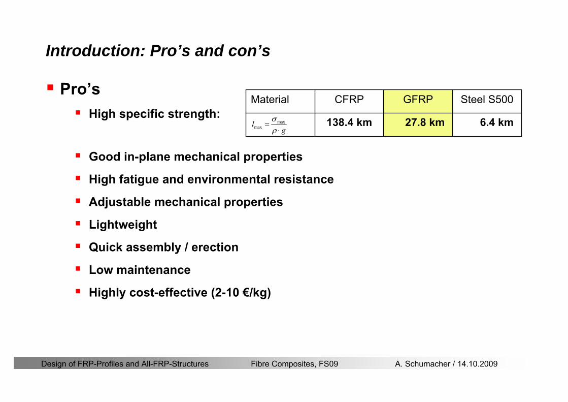
Design of FRP-Profiles and All-FRP-Structures Fibre Composites FS09 A Schumacher 14102009
Introduction Prorsquos and conrsquos
ProrsquosHigh specific strength
Good in-plane mechanical properties
High fatigue and environmental resistance
Adjustable mechanical properties
Lightweight
Quick assembly erection
Low maintenance
Highly cost-effective (2-10 eurokg)
maxmaxl g
σρ
=sdot
1384 km
CFRP
64 km278 km
Steel S500GFRPMaterial
Design of FRP-Profiles and All-FRP-Structures Fibre Composites FS09 A Schumacher 14102009
Introduction Prorsquos and conrsquos
ConrsquosLightweight
Brittle
High initial costs
Low to moderate application temperature (-20 up to 80 degC)
Low fire resistance (sometimes with unhealthy gases)
Design of FRP-Profiles and All-FRP-Structures Fibre Composites FS09 A Schumacher 14102009
Introduction Common profiles
Structural profilesMost structural profiles produced in conventional profile shapes similar to metallic materials
Similarity in geom and properties however no standard geom mechanical and physical properties used by all manufacturers
Structural profiles Non-structural profiles
Design of FRP-Profiles and All-FRP-Structures Fibre Composites FS09 A Schumacher 14102009
Introduction Examples
Footbridges
Fiberline Bridge in Kolding DK
Span 40 mCost 05 mio CHFOnly Fiberline standard profiles used
httpwwwfiberlinecomgbcasestoriescase1837asp
Pontresina bridge Switzerland
Span 2 x 125 mWeight 33 tons (installation by helicopter)
httpwwwfiberlinecomgbcasestoriescase1830asp
Design of FRP-Profiles and All-FRP-Structures Fibre Composites FS09 A Schumacher 14102009
Introduction Examples
Footbridges
Composite pedestrian bridge in Lleida Spain
Span 38 mWidth 30 m
httpwwwfiberlinecomgbcasestoriescase2828asp
Design of FRP-Profiles and All-FRP-Structures Fibre Composites FS09 A Schumacher 14102009
Introduction Examples (ASSET Profile)
Road bridges
West Mill Bridge England
Span 10 mWidth 68 mLoad capacity 46 tons
httpwwwfiberlinecomgbcasestoriescase3903asp
Klipphausen Bridge Germany
Span 68 mWidth 60 mLoad capacity 40 tons
httpwwwfiberlinecomgbcasestoriescase6314asp
Design of FRP-Profiles and All-FRP-Structures Fibre Composites FS09 A Schumacher 14102009
Introduction Examples
Bridgedeck (Footbridges)Wuumlrenlos Switzerland Loopersteg Switzerland
Design of FRP-Profiles and All-FRP-Structures Fibre Composites FS09 A Schumacher 14102009
Introduction Examples
Buildings
Eyecatcher Building Basel Switzerland
Height 15 mStoreys 5
httpwwwfiberlinecomgbcasestoriescase1835asp
Project Maagtechnic
Design of FRP-Profiles and All-FRP-Structures Fibre Composites FS09 A Schumacher 14102009
Introduction Examples
Laboratory bridgeEmpa Laboratory Bridge Switzerland
Span 19 mWidth 16 mLoad capacity 15 tons
Design of FRP-Profiles and All-FRP-Structures Fibre Composites FS09 A Schumacher 14102009
Introduction Examples
Noise barrier SBB
Goumlschenen Switzerland
Project Maagtechnic
Design of FRP-Profiles and All-FRP-Structures Fibre Composites FS09 A Schumacher 14102009
Introduction Examples
Balconies
Switzerland
Project Maagtechnic
Design of FRP-Profiles and All-FRP-Structures Fibre Composites FS09 A Schumacher 14102009
Introduction Examples
RailingsOensingen Switzerland
Heineken brewery Switzerland
Design of FRP-Profiles and All-FRP-Structures Fibre Composites FS09 A Schumacher 14102009
Introduction Application
Applications where GFRP structures are competitive
Significant corrosion and chemical resistance is required(Food and chemical processing plants cooling towers offshore platforms hellip)
Electromagnetic transparency or electrical insulation is required
Light-weight is cost essential(fast deployment hellip)
Prestige and demonstration objects (eg Novartis Campus Entrance Building)
Photo Prof Th Keller EPFL
Design of FRP-Profiles and All-FRP-Structures Fibre Composites FS09 A Schumacher 14102009
Material
Design of FRP-Profiles and All-FRP-Structures Fibre Composites FS09 A Schumacher 14102009
Only pultruded GFRP profiles will be considered in this lecture
Production of profiles with constant cross-section along the length
High quality
Continuous longitudinal fiber bundles and filament mats
Pultrusion line
Material Pultrusion process
Design of FRP-Profiles and All-FRP-Structures Fibre Composites FS09 A Schumacher 14102009
Material Components
Pultruded profiles contain three primary componentsreinforcement
Matrix
Supplementaryconstituents
polyesterepoxyphenol
polymerisation agentsfillersadditives
Design of FRP-Profiles and All-FRP-Structures Fibre Composites FS09 A Schumacher 14102009
Material Shapes of pultruded profiles
Available Profiles on Stock
Length up to 12 m
Special cross-sections can be designed and ordered(several kilometres are necessary rarr special tools have to be designed)
Design of FRP-Profiles and All-FRP-Structures Fibre Composites FS09 A Schumacher 14102009
Material Durability
Various environmental and load conditions that affect durability of (G)FRPs in terms of strength stiffness fibermatrix interface integrity cracking
watersea waterchemical solutionsprolonged freezingthermal cycling (freeze-thaw)elevated temperature exposureUV radiationcreep and relaxationfatiguefirehellip
Design of FRP-Profiles and All-FRP-Structures Fibre Composites FS09 A Schumacher 14102009
Material Durability
Environmental reduction factor for different FRP systems and exposure conditions
070Aramidepoxy
050Glassepoxy(chemical plants)
085CarbonepoxyAgressive environ
075Aramidepoxyparking garages)
065Glassepoxy(bridges piers
085CarbonepoxyExterior exposure
085Aramidepoxy
075Glassepoxy
095CarbonepoxyInterior exposure
Environ reductionFiber resin typeExposure condition
Design of FRP-Profiles and All-FRP-Structures Fibre Composites FS09 A Schumacher 14102009
Material Durability
GFRP is more susceptible to degradation than CFRP by the following effects
alkaline effects (caution when GFRP in contact with concrete)acid effectssalt effectsfatigueUV radiation
Fire protection is a major (unsolved) issue for (G)FRP structural elements and components
Smoke generation and toxicity must be consideredStrength of GFRP is affected by fatigue loading(more than CFRP)
Design of FRP-Profiles and All-FRP-Structures Fibre Composites FS09 A Schumacher 14102009
Material Manufacturers
GFRP profiles available on stock
In Europe two companies pultrude FRP-Profiles
Fiberline Composites Denmarkwwwfiberlinecom
Fiberline Design Manual (wwwfiberlinedk)rarr helpful tool to design structures
(material properties geometries connections hellip)
Top Glass Italywwwtopglassit
Design of FRP-Profiles and All-FRP-Structures Fibre Composites FS09 A Schumacher 14102009
Material Manufacturers
GFRP profiles available on stock
In North America
Strongwell USAwwwstrongwellcom
Creative Pultrusions USAwwwcreativepultrusionscom
Bedford Reinforced Plastics USAwwwbedfordplasticscom
Design of FRP-Profiles and All-FRP-Structures Fibre Composites FS09 A Schumacher 14102009
Design Concept
Design of FRP-Profiles and All-FRP-Structures Fibre Composites FS09 A Schumacher 14102009
Design Concept Basic Assumptions
Definitions and directions
Design of FRP-Profiles and All-FRP-Structures Fibre Composites FS09 A Schumacher 14102009
Design Concept
Codes
Every manufacturer has its own profile design rarr No European Design Code is available (only EN13706 about testing and notation)
There exists European guidelines EUROCOMP 1996 Design CodeEUROCOMP 1996 Handbook
Fiberline Design Manual is based on Eurocomp 1996
Design concept (according to Eurocodes and Swisscodes)
Partial safety factors
Measured material parameters
Rules for bolted connections
Design of FRP-Profiles and All-FRP-Structures Fibre Composites FS09 A Schumacher 14102009
Design Concept
Concept of Limit State Design (According to Euro Codes and Swiss Codes)
Ultimate limit stress
Ed le Rd
Ed hellip Calculated stress (including load factors) hellip SIA260 261
Rd hellip Rated value of the resistance capability
where
Rk hellip the calculated resistance capability
kd mγ=
RR
Design of FRP-Profiles and All-FRP-Structures Fibre Composites FS09 A Schumacher 14102009
101020Production process
Operating temperature
111116Degree of postcuring
115115225Derivation of mat properties
FiberlineMinMaxDescriptionCoefficient
Design Concept
Reduction coefficient m m1 m2 m3 m4γ γ γ γ γ= sdot sdot sdot
m1γ
m2γ
m3γ
m4γ
mγ mγ
31312580
2510-20 +60
Long-term loadShort-term load
Operatingtemperature degC m4γ
Design of FRP-Profiles and All-FRP-Structures Fibre Composites FS09 A Schumacher 14102009
Design Concept
Serviceability limit states
Ed le Cd
Ed hellip the crucial action effect due to the load cases considered inthe investigated dimensioning situation Typically maximaldeflection response of the structure
Cd hellip corresponding serviceability limit SIA 261
Design of FRP-Profiles and All-FRP-Structures Fibre Composites FS09 A Schumacher 14102009
Design Concept Basic Assumptions
Material Properties stength values (Fiberline Profiles)
Design of FRP-Profiles and All-FRP-Structures Fibre Composites FS09 A Schumacher 14102009
Design Concept Basic Assumptions
Material Properties stiffness values (Fiberline Profiles)
Design of FRP-Profiles and All-FRP-Structures Fibre Composites FS09 A Schumacher 14102009
Design Concept Basic Assumptions
Typical data sheet of a profile (Fiberline I-Profile)
Design of FRP-Profiles and All-FRP-Structures Fibre Composites FS09 A Schumacher 14102009
Bending Beam
Design of FRP-Profiles and All-FRP-Structures Fibre Composites FS09 A Schumacher 14102009
Bending Beam Design of hellip
Calculate bending moments Md and shear forces Qd acting on the profile using the partial coefficient (SIA 260 261)
Ultimate limit state
Bending
Shear
Ak hellip relevant shear area
d max d max 0max
M MW Wy z b
mzy
fσ γ
⎛ ⎞⎜ ⎟⎜ ⎟⎜ ⎟⎜ ⎟⎝ ⎠
deg= + le
d maxmax
kyAy
m
Q fττ γ= le
Design of FRP-Profiles and All-FRP-Structures Fibre Composites FS09 A Schumacher 14102009
Bending Beam Design of hellip
Serviceability limit state
Deflection limit
hellip typically selected between 200 and 400given by SIA 261 or the building owner
hellip calculated including shear deformations
Vibrations
Light-weighted and lsquosoftrsquo structures are susceptible to vibrations (traffic wind the movement of people hellip)
max 1wL αlt
α
maxw
Design of FRP-Profiles and All-FRP-Structures Fibre Composites FS09 A Schumacher 14102009
Bending Beam Timoshenko Theory
Pultruded profiles have a low shear modulus rarr shear deformation must be taken into account
Several bending theories have been published for beams
Euler-Bernoulli theory (1702)
Timoshenko theory (1968)
Higher order beam theory
A simply supported beam with a symmetric cross-section is discussed
Design of FRP-Profiles and All-FRP-Structures Fibre Composites FS09 A Schumacher 14102009
Bending Beam Timoshenko Theory
Cross-sections planeand perpendicular
1 degree of freedom
w
Cross-sections plane butNOT perpendicular
2 degrees of freedom
w and ψ
Cross-sections do NOTremain plane
3+ degrees of freedom
w ψ and hellip
Design of FRP-Profiles and All-FRP-Structures Fibre Composites FS09 A Schumacher 14102009
Bending Beam Euler vs Timoshenko Theory
Kinematic relationships
( )( )
( )
2 0
x x
y
xx xx
yxxy
u y w xu w x
u y w xxuu
y x
ε
ε
=minus sdot=
part= =minus sdotpartpartpart= + =
part part
( )( )
( )
2 ( ) ( )
x
y
xx x
yxxy x
u y xu w x
u y xxuu x w xy x
ψ
ε ψ
ε ψ
=minus sdot=
part= =minus sdotpartpartpart= + =minus +
part part
Hookrsquos law
0degE and G 2x x xy xyσ ε τ ε= sdot = sdot
z0deg E Iz x xxQS
M y dydz wσ= minus sdot sdot = sdot sdotintint
( )
z0deg E I
z x xQS
y xQS
M y dydz
Q dydz w GA
σ ψ
κ τ ψ κ
= minus sdot sdot = sdot
= sdot = minus sdot sdot
intint
intint
Design of FRP-Profiles and All-FRP-Structures Fibre Composites FS09 A Schumacher 14102009
Bending Beam Euler vs Timoshenko Theory
Equilibrium
Solution for the simply supported beam (distributed load)
In a first approximation the deflections are calculated by direct integration of
z0deg
( ) E IxxM xw = sdot
( )( )z0deg
( ) E I 0x
x
xx x
xx x
q x w GAw GA
QM Q
ψ κψ ψ κ
minus minus sdot sdot
sdot + minus sdot sdot
=minus =
= =minus
Equilibrium on an infinitesimal beam element
Coupled second order differential equation
21 1( ) (0) 0 and ( ) 02 2
M x qLx qx w w L= minus = =
( )3 2 3
0deg z
( ) 224 E Iqxw x L Lx x= sdot minus +sdot sdot
2
0deg z
1 1 1E I 2 2xxw qLx qx⎛ ⎞= minus⎜ ⎟sdot ⎝ ⎠
(0) 0 and ( ) 0(0) 0 (0) 0 and ( ) 0 ( ) 0 x x
w w LM M L Lψ ψ
= == rarr = = rarr =
Functions4 3 2
1 2 3 4 53 2
1 2 3 4
( )
( )
w x A x A x A x A x A
x B x B x B x Bψ
= + + + +
= + + +
Design of FRP-Profiles and All-FRP-Structures Fibre Composites FS09 A Schumacher 14102009
Put in and solve for the coefficients rarr
Bending Beam Euler vs Timoshenko Theory
Use the boundary conditions and the second differential eq to calculate A1 ndash A5
( )0deg z E I 0xx xw GAψ ψ κsdot + minus sdot sdot =
1 01 1 3 3
2 02 2 4 4
24 E I4 2GA
6 E I3 GA
z
z
AB A B A
AB A B A
κ
κ
deg
deg
sdot= minus = minus minus
sdotsdot
= minus = minus minussdot
( ) ( )( )2 2
0
( )2 GA 24 E Iz
qx L x L Lx xqx L xw x
κ deg
minus + minusminus= +
sdot sdot sdot
Deflection at midspan
4
0
52 384 E Iz
qLLw⎛ ⎞⎜ ⎟⎝ ⎠
deg
sdot= sdot4 2
0
52 384 E I 8 GAz
qL q LLw κ⎛ ⎞ +⎜ ⎟⎝ ⎠
deg
sdot sdot= sdot sdot sdot
Design of FRP-Profiles and All-FRP-Structures Fibre Composites FS09 A Schumacher 14102009
General expression for the total beam deflection as a sum of the deflection due to bending and shear
GAxf
IExfxwz sdot+=
deg κ)()()( 2
0
1
Cantilever beam
Simply supported
Concentrated load (P)
Uniformly distr load (q)
Concentrated load (P)
Uniformly distr load (q)
Beam )( max1 wf
3845 4qLsdot
48
3PL
8
4qL
3
3PL
)( max1 wf
8
2qL
4PL
2
2qL
PL
)( maxwx
2L
2L
L
L
Bending Beam Euler vs Timoshenko Theory
Design of FRP-Profiles and All-FRP-Structures Fibre Composites FS09 A Schumacher 14102009
Bending Beam Euler vs Timoshenko Theory
Example influence of the shear deformation
Profile 300 x 150 mm I-beam
Load uniformly distributed
General rule of thumbfor GFRP beams withspandepth gt 25 sheardeformation can beignored
Design of FRP-Profiles and All-FRP-Structures Fibre Composites FS09 A Schumacher 14102009
Bending Beam Example
Choose an appropriate Profile for the following specifications
1 Deflections and loading
=
=
==
1300 rarr wmax=001 mwmaxL
10 kNmqdser
13 kNmqduls
30 mL
max
4 2
0
5384 E I 8 GA
d ser d serz
q L q Lw κ+
deg
sdot sdot= sdot sdot sdot
2
maxz8 2 I
d ulsq L hσ sdot= sdot
maxky
12 Ad ulsq L
τ sdot=
Design of FRP-Profiles and All-FRP-Structures Fibre Composites FS09 A Schumacher 14102009
Bending Beam Example
2 Find a profile with sufficient bending stiffness
Shear deformations are neglected in a first step
rarr from specification table choose I 240x120x12 rarr
3 Check the bending and shear stresses
6 24
0 max
1054 10 Nm5
E I 384d ser
zq Lwdeg = sdot
sdotsdotge
6 20 1369 10 NmE Izdeg = sdot
2
maxz
358 MPa8 2 Id ulsq L hσ sdot= =sdot
max
ky
1 71 MPa2 Ad ulsq L
τ sdot= =
0 185 MPab df degle =
20 MPadfτle =
Design of FRP-Profiles and All-FRP-Structures Fibre Composites FS09 A Schumacher 14102009
Bending Beam Example
m10398384
5 32
0
4
maxminus
deg
sdot=sdotsdotsdot
+sdot
sdot=
GALq
IELq
w serd
z
serd
κ
4 Check deflection (including shear deformation)
5 Remarks
The design of GFRP-profiles is mostly driven by serviceability criteria
Start the design iteration procedure using the maximal deflection criterion
max 001 mwle =
m10198384
5 32
0
4
maxminus
deg
sdot=sdot
sdot+
sdotsdot
=web
serd
z
serd
GALq
IELq
w
(77 mm) (16 mm)
Design of FRP-Profiles and All-FRP-Structures Fibre Composites FS09 A Schumacher 14102009
Bending Beam Stability problems
Lateral-torsional bucklingFlange (compressive) displace laterally to the transverse load direction
Torsional stiffness is too low (especially for open section profiles)
Theoretical calculations or design measuresrarr see eg LP Kollaacuter 2003
Mechanics of composite structuresExample
Compressive flanges are kept in place by connection to the bridge deck
Design of FRP-Profiles and All-FRP-Structures Fibre Composites FS09 A Schumacher 14102009
Bending Beam Stability problems
Flange (compressive) displaces in the direction of the transverse load
Low bending stiffness perpendicular to the pultrusion direction
Weak fiber mats
Local buckling of walls due to in-plane compression
Local buckling of walls due to in-plane shear
Web crushing and web buckling in transverse direction
Design of FRP-Profiles and All-FRP-Structures Fibre Composites FS09 A Schumacher 14102009
Axial Members
Design of FRP-Profiles and All-FRP-Structures Fibre Composites FS09 A Schumacher 14102009
Axial Members Tension
Ultimate limit state under axial tension Nd
Serviceability limit state
Remark The critical aspect of axial members in tension are neither the serviceability nor the ultimate limit state Critical is the load transfer to the GFRP profile
0NdA
tm
fγ
degle
0deg
N LE Axδ sdot= sdot
Design of FRP-Profiles and All-FRP-Structures Fibre Composites FS09 A Schumacher 14102009
Axial Members Compression
Ultimate limit state under axial compression Nd
hellip maximal compressive load
hellip Euler load
hellip Buckling length for columns
hellip coefficient for Youngrsquos modulus = 13
cc
Euler
FNd F1 N
le+
c0degC
A fF
mγsdot
=
20
Euler 2
Nm E k
E IL
πγ
degsdot sdot=
sdot
kL
m Eγ
Design of FRP-Profiles and All-FRP-Structures Fibre Composites FS09 A Schumacher 14102009
Axial Members Compression
The influence of shear deformation should be considered but in the most cases the influence will be small (less than 5)
Local buckling should be considered for short columns
For more information on the various buckling modes and effects rarr see LP Kollaacuter 2003 Mechanics of composite structures
Global buckling Local buckling
Design of FRP-Profiles and All-FRP-Structures Fibre Composites FS09 A Schumacher 14102009
Connections
Design of FRP-Profiles and All-FRP-Structures Fibre Composites FS09 A Schumacher 14102009
Connections Introduction
Design of FRP-Profiles and All-FRP-Structures Fibre Composites FS09 A Schumacher 14102009
Connections Introduction
(from Eurocomp Design Code 1996)
Design of FRP-Profiles and All-FRP-Structures Fibre Composites FS09 A Schumacher 14102009
Connections Bolted joints
Bolts = Stress concentration in the profile and the bolt
It is necessary to ensure that the bolts and the profilecan withstand this concentrated local stress compression
It is necessary to ensure that the region surroundinga group of bolts will not be torn out of the profile
Basic failure modesin bolted shearconnections
bolt shear failure
Design of FRP-Profiles and All-FRP-Structures Fibre Composites FS09 A Schumacher 14102009
Connections Bolted joints
The design procedure is comparable to the one for steel connections but since there exist no standard GFRP material rarr each manufacturer has its own design rules for bolted joints
IMPORTANT REMARKS
The direction of pultrusion and the direction of the force is RELEVANT(anisotropic material)
Use stainless or galvanised steel
Do not cut threads in the composite material
Use screws with shafts
Design of FRP-Profiles and All-FRP-Structures Fibre Composites FS09 A Schumacher 14102009
Calculation of load bearing capacity of bolts
Shear in longitudinal direction (0deg)
Shear in transverse direction (90deg)
Tensile force
Minimum distances
Connections Bolted joints (Fiberline recommendations)
Design of FRP-Profiles and All-FRP-Structures Fibre Composites FS09 A Schumacher 14102009
Joint capacity tables available for shear and tension
m
150 MPa( 13)B d
d tP γsdot sdot=
=
Shear in longitudinal direction 0deg
m
70 MPa( 13)B d
d tP γsdot sdot=
=
Shear in transverse direction 90deg
Connections Bolted joints (Fiberline recommendations)
Design of FRP-Profiles and All-FRP-Structures Fibre Composites FS09 A Schumacher 14102009
Bolted connection in shear eg shear in longitudinal direction
Connections Bolted joints (Fiberline recommendations)
γmPBolt le dt720 MPaγmPBolt le dt240 MPa
γmPBolt le dt240 MPa γmPBolt le dt240 MPaγmPBolt le dt150 MPa
Design of FRP-Profiles and All-FRP-Structures Fibre Composites FS09 A Schumacher 14102009
Bolted connections in tension
Static conditions
Bolt Tearing of bolt in threaded cross-section
Laminate Shear fracture at rim of washer
Geometry and strength
Diameter of washer2d
Tensile strength of bolt hellipfyk
Shear strength of laminatehellipfτ
Thickness of laminatet
Stress area of the boltAs
Diameter of the boltd
s ykd m
A fP γ
sdotle
2d m
d t fP τπγ
sdot sdot sdot sdotle
Connections Bolted joints (Fiberline recommendations)
Design of FRP-Profiles and All-FRP-Structures Fibre Composites FS09 A Schumacher 14102009
Connections Bonded joints
Using an adhesive agent for joining profiles can have advantages
Easy to use easy to make aesthetic joints
Typically more rigid than bolted joints
Glued joints subjected to dynamic loads are good
But be careful hellipAdhesive agents have properties that depend on time temperature humidity hellip
Failure in glued joints takes place suddenly (brittle behaviour)
The load-bearing capacity is not proportional to the area which is glued
The design of bonded joints may be based onAnalytical models for plate-to-plate connections (see Eurocomp 1996 Design Code)
Design guidelines supplemented by testing
Finite element analysis
Design of FRP-Profiles and All-FRP-Structures Fibre Composites FS09 A Schumacher 14102009
Connections Bonded joints
A bonded joint has the following three primary failure modes
adhesive failure
cohesive failure of adhesive
cohesive failure of adherend
The design of any bonded joint shall satisfy the following conditions
allowable shear stress in the adhesive is not exceeded
allowable tensile (peel) stress in the adhesive is not exceeded
allowable through-thickness tensile stress of the adhesive is not exceeded
allowable in-plane shear stress of the adherend should not be exceeded
The calculation of the stresses has to be done very carefully Often calculations are supplemented by testing
Design of FRP-Profiles and All-FRP-Structures Fibre Composites FS09 A Schumacher 14102009
Connections Bonded joints
Different types of bonded joint configurations
Research on bonded joints for structuralapplications
Design of FRP-Profiles and All-FRP-Structures Fibre Composites FS09 A Schumacher 14102009
Connections Other joints
Brackets for assembly (Fiberline)
Custom pultruded connections
Design of FRP-Profiles and All-FRP-Structures Fibre Composites FS09 A Schumacher 14102009
GFRP Some final remarks
Perpendicular to the direction of pultrusion the material is WEAK and SOFTrarr avoid such loadings if possible
In order to use pultruded GFRP-profiles economically the design must be done in a clever way eg for bridges the railings should be used as part of the load-bearing structure
GFRP structures are very light rarr vibration problems may occur
Design of FRP-Profiles and All-FRP-Structures Fibre Composites FS09 A Schumacher 14102009
Introduction Prorsquos and conrsquos
ConrsquosLightweight
Brittle
High initial costs
Low to moderate application temperature (-20 up to 80 degC)
Low fire resistance (sometimes with unhealthy gases)
Design of FRP-Profiles and All-FRP-Structures Fibre Composites FS09 A Schumacher 14102009
Introduction Common profiles
Structural profilesMost structural profiles produced in conventional profile shapes similar to metallic materials
Similarity in geom and properties however no standard geom mechanical and physical properties used by all manufacturers
Structural profiles Non-structural profiles
Design of FRP-Profiles and All-FRP-Structures Fibre Composites FS09 A Schumacher 14102009
Introduction Examples
Footbridges
Fiberline Bridge in Kolding DK
Span 40 mCost 05 mio CHFOnly Fiberline standard profiles used
httpwwwfiberlinecomgbcasestoriescase1837asp
Pontresina bridge Switzerland
Span 2 x 125 mWeight 33 tons (installation by helicopter)
httpwwwfiberlinecomgbcasestoriescase1830asp
Design of FRP-Profiles and All-FRP-Structures Fibre Composites FS09 A Schumacher 14102009
Introduction Examples
Footbridges
Composite pedestrian bridge in Lleida Spain
Span 38 mWidth 30 m
httpwwwfiberlinecomgbcasestoriescase2828asp
Design of FRP-Profiles and All-FRP-Structures Fibre Composites FS09 A Schumacher 14102009
Introduction Examples (ASSET Profile)
Road bridges
West Mill Bridge England
Span 10 mWidth 68 mLoad capacity 46 tons
httpwwwfiberlinecomgbcasestoriescase3903asp
Klipphausen Bridge Germany
Span 68 mWidth 60 mLoad capacity 40 tons
httpwwwfiberlinecomgbcasestoriescase6314asp
Design of FRP-Profiles and All-FRP-Structures Fibre Composites FS09 A Schumacher 14102009
Introduction Examples
Bridgedeck (Footbridges)Wuumlrenlos Switzerland Loopersteg Switzerland
Design of FRP-Profiles and All-FRP-Structures Fibre Composites FS09 A Schumacher 14102009
Introduction Examples
Buildings
Eyecatcher Building Basel Switzerland
Height 15 mStoreys 5
httpwwwfiberlinecomgbcasestoriescase1835asp
Project Maagtechnic
Design of FRP-Profiles and All-FRP-Structures Fibre Composites FS09 A Schumacher 14102009
Introduction Examples
Laboratory bridgeEmpa Laboratory Bridge Switzerland
Span 19 mWidth 16 mLoad capacity 15 tons
Design of FRP-Profiles and All-FRP-Structures Fibre Composites FS09 A Schumacher 14102009
Introduction Examples
Noise barrier SBB
Goumlschenen Switzerland
Project Maagtechnic
Design of FRP-Profiles and All-FRP-Structures Fibre Composites FS09 A Schumacher 14102009
Introduction Examples
Balconies
Switzerland
Project Maagtechnic
Design of FRP-Profiles and All-FRP-Structures Fibre Composites FS09 A Schumacher 14102009
Introduction Examples
RailingsOensingen Switzerland
Heineken brewery Switzerland
Design of FRP-Profiles and All-FRP-Structures Fibre Composites FS09 A Schumacher 14102009
Introduction Application
Applications where GFRP structures are competitive
Significant corrosion and chemical resistance is required(Food and chemical processing plants cooling towers offshore platforms hellip)
Electromagnetic transparency or electrical insulation is required
Light-weight is cost essential(fast deployment hellip)
Prestige and demonstration objects (eg Novartis Campus Entrance Building)
Photo Prof Th Keller EPFL
Design of FRP-Profiles and All-FRP-Structures Fibre Composites FS09 A Schumacher 14102009
Material
Design of FRP-Profiles and All-FRP-Structures Fibre Composites FS09 A Schumacher 14102009
Only pultruded GFRP profiles will be considered in this lecture
Production of profiles with constant cross-section along the length
High quality
Continuous longitudinal fiber bundles and filament mats
Pultrusion line
Material Pultrusion process
Design of FRP-Profiles and All-FRP-Structures Fibre Composites FS09 A Schumacher 14102009
Material Components
Pultruded profiles contain three primary componentsreinforcement
Matrix
Supplementaryconstituents
polyesterepoxyphenol
polymerisation agentsfillersadditives
Design of FRP-Profiles and All-FRP-Structures Fibre Composites FS09 A Schumacher 14102009
Material Shapes of pultruded profiles
Available Profiles on Stock
Length up to 12 m
Special cross-sections can be designed and ordered(several kilometres are necessary rarr special tools have to be designed)
Design of FRP-Profiles and All-FRP-Structures Fibre Composites FS09 A Schumacher 14102009
Material Durability
Various environmental and load conditions that affect durability of (G)FRPs in terms of strength stiffness fibermatrix interface integrity cracking
watersea waterchemical solutionsprolonged freezingthermal cycling (freeze-thaw)elevated temperature exposureUV radiationcreep and relaxationfatiguefirehellip
Design of FRP-Profiles and All-FRP-Structures Fibre Composites FS09 A Schumacher 14102009
Material Durability
Environmental reduction factor for different FRP systems and exposure conditions
070Aramidepoxy
050Glassepoxy(chemical plants)
085CarbonepoxyAgressive environ
075Aramidepoxyparking garages)
065Glassepoxy(bridges piers
085CarbonepoxyExterior exposure
085Aramidepoxy
075Glassepoxy
095CarbonepoxyInterior exposure
Environ reductionFiber resin typeExposure condition
Design of FRP-Profiles and All-FRP-Structures Fibre Composites FS09 A Schumacher 14102009
Material Durability
GFRP is more susceptible to degradation than CFRP by the following effects
alkaline effects (caution when GFRP in contact with concrete)acid effectssalt effectsfatigueUV radiation
Fire protection is a major (unsolved) issue for (G)FRP structural elements and components
Smoke generation and toxicity must be consideredStrength of GFRP is affected by fatigue loading(more than CFRP)
Design of FRP-Profiles and All-FRP-Structures Fibre Composites FS09 A Schumacher 14102009
Material Manufacturers
GFRP profiles available on stock
In Europe two companies pultrude FRP-Profiles
Fiberline Composites Denmarkwwwfiberlinecom
Fiberline Design Manual (wwwfiberlinedk)rarr helpful tool to design structures
(material properties geometries connections hellip)
Top Glass Italywwwtopglassit
Design of FRP-Profiles and All-FRP-Structures Fibre Composites FS09 A Schumacher 14102009
Material Manufacturers
GFRP profiles available on stock
In North America
Strongwell USAwwwstrongwellcom
Creative Pultrusions USAwwwcreativepultrusionscom
Bedford Reinforced Plastics USAwwwbedfordplasticscom
Design of FRP-Profiles and All-FRP-Structures Fibre Composites FS09 A Schumacher 14102009
Design Concept
Design of FRP-Profiles and All-FRP-Structures Fibre Composites FS09 A Schumacher 14102009
Design Concept Basic Assumptions
Definitions and directions
Design of FRP-Profiles and All-FRP-Structures Fibre Composites FS09 A Schumacher 14102009
Design Concept
Codes
Every manufacturer has its own profile design rarr No European Design Code is available (only EN13706 about testing and notation)
There exists European guidelines EUROCOMP 1996 Design CodeEUROCOMP 1996 Handbook
Fiberline Design Manual is based on Eurocomp 1996
Design concept (according to Eurocodes and Swisscodes)
Partial safety factors
Measured material parameters
Rules for bolted connections
Design of FRP-Profiles and All-FRP-Structures Fibre Composites FS09 A Schumacher 14102009
Design Concept
Concept of Limit State Design (According to Euro Codes and Swiss Codes)
Ultimate limit stress
Ed le Rd
Ed hellip Calculated stress (including load factors) hellip SIA260 261
Rd hellip Rated value of the resistance capability
where
Rk hellip the calculated resistance capability
kd mγ=
RR
Design of FRP-Profiles and All-FRP-Structures Fibre Composites FS09 A Schumacher 14102009
101020Production process
Operating temperature
111116Degree of postcuring
115115225Derivation of mat properties
FiberlineMinMaxDescriptionCoefficient
Design Concept
Reduction coefficient m m1 m2 m3 m4γ γ γ γ γ= sdot sdot sdot
m1γ
m2γ
m3γ
m4γ
mγ mγ
31312580
2510-20 +60
Long-term loadShort-term load
Operatingtemperature degC m4γ
Design of FRP-Profiles and All-FRP-Structures Fibre Composites FS09 A Schumacher 14102009
Design Concept
Serviceability limit states
Ed le Cd
Ed hellip the crucial action effect due to the load cases considered inthe investigated dimensioning situation Typically maximaldeflection response of the structure
Cd hellip corresponding serviceability limit SIA 261
Design of FRP-Profiles and All-FRP-Structures Fibre Composites FS09 A Schumacher 14102009
Design Concept Basic Assumptions
Material Properties stength values (Fiberline Profiles)
Design of FRP-Profiles and All-FRP-Structures Fibre Composites FS09 A Schumacher 14102009
Design Concept Basic Assumptions
Material Properties stiffness values (Fiberline Profiles)
Design of FRP-Profiles and All-FRP-Structures Fibre Composites FS09 A Schumacher 14102009
Design Concept Basic Assumptions
Typical data sheet of a profile (Fiberline I-Profile)
Design of FRP-Profiles and All-FRP-Structures Fibre Composites FS09 A Schumacher 14102009
Bending Beam
Design of FRP-Profiles and All-FRP-Structures Fibre Composites FS09 A Schumacher 14102009
Bending Beam Design of hellip
Calculate bending moments Md and shear forces Qd acting on the profile using the partial coefficient (SIA 260 261)
Ultimate limit state
Bending
Shear
Ak hellip relevant shear area
d max d max 0max
M MW Wy z b
mzy
fσ γ
⎛ ⎞⎜ ⎟⎜ ⎟⎜ ⎟⎜ ⎟⎝ ⎠
deg= + le
d maxmax
kyAy
m
Q fττ γ= le
Design of FRP-Profiles and All-FRP-Structures Fibre Composites FS09 A Schumacher 14102009
Bending Beam Design of hellip
Serviceability limit state
Deflection limit
hellip typically selected between 200 and 400given by SIA 261 or the building owner
hellip calculated including shear deformations
Vibrations
Light-weighted and lsquosoftrsquo structures are susceptible to vibrations (traffic wind the movement of people hellip)
max 1wL αlt
α
maxw
Design of FRP-Profiles and All-FRP-Structures Fibre Composites FS09 A Schumacher 14102009
Bending Beam Timoshenko Theory
Pultruded profiles have a low shear modulus rarr shear deformation must be taken into account
Several bending theories have been published for beams
Euler-Bernoulli theory (1702)
Timoshenko theory (1968)
Higher order beam theory
A simply supported beam with a symmetric cross-section is discussed
Design of FRP-Profiles and All-FRP-Structures Fibre Composites FS09 A Schumacher 14102009
Bending Beam Timoshenko Theory
Cross-sections planeand perpendicular
1 degree of freedom
w
Cross-sections plane butNOT perpendicular
2 degrees of freedom
w and ψ
Cross-sections do NOTremain plane
3+ degrees of freedom
w ψ and hellip
Design of FRP-Profiles and All-FRP-Structures Fibre Composites FS09 A Schumacher 14102009
Bending Beam Euler vs Timoshenko Theory
Kinematic relationships
( )( )
( )
2 0
x x
y
xx xx
yxxy
u y w xu w x
u y w xxuu
y x
ε
ε
=minus sdot=
part= =minus sdotpartpartpart= + =
part part
( )( )
( )
2 ( ) ( )
x
y
xx x
yxxy x
u y xu w x
u y xxuu x w xy x
ψ
ε ψ
ε ψ
=minus sdot=
part= =minus sdotpartpartpart= + =minus +
part part
Hookrsquos law
0degE and G 2x x xy xyσ ε τ ε= sdot = sdot
z0deg E Iz x xxQS
M y dydz wσ= minus sdot sdot = sdot sdotintint
( )
z0deg E I
z x xQS
y xQS
M y dydz
Q dydz w GA
σ ψ
κ τ ψ κ
= minus sdot sdot = sdot
= sdot = minus sdot sdot
intint
intint
Design of FRP-Profiles and All-FRP-Structures Fibre Composites FS09 A Schumacher 14102009
Bending Beam Euler vs Timoshenko Theory
Equilibrium
Solution for the simply supported beam (distributed load)
In a first approximation the deflections are calculated by direct integration of
z0deg
( ) E IxxM xw = sdot
( )( )z0deg
( ) E I 0x
x
xx x
xx x
q x w GAw GA
QM Q
ψ κψ ψ κ
minus minus sdot sdot
sdot + minus sdot sdot
=minus =
= =minus
Equilibrium on an infinitesimal beam element
Coupled second order differential equation
21 1( ) (0) 0 and ( ) 02 2
M x qLx qx w w L= minus = =
( )3 2 3
0deg z
( ) 224 E Iqxw x L Lx x= sdot minus +sdot sdot
2
0deg z
1 1 1E I 2 2xxw qLx qx⎛ ⎞= minus⎜ ⎟sdot ⎝ ⎠
(0) 0 and ( ) 0(0) 0 (0) 0 and ( ) 0 ( ) 0 x x
w w LM M L Lψ ψ
= == rarr = = rarr =
Functions4 3 2
1 2 3 4 53 2
1 2 3 4
( )
( )
w x A x A x A x A x A
x B x B x B x Bψ
= + + + +
= + + +
Design of FRP-Profiles and All-FRP-Structures Fibre Composites FS09 A Schumacher 14102009
Put in and solve for the coefficients rarr
Bending Beam Euler vs Timoshenko Theory
Use the boundary conditions and the second differential eq to calculate A1 ndash A5
( )0deg z E I 0xx xw GAψ ψ κsdot + minus sdot sdot =
1 01 1 3 3
2 02 2 4 4
24 E I4 2GA
6 E I3 GA
z
z
AB A B A
AB A B A
κ
κ
deg
deg
sdot= minus = minus minus
sdotsdot
= minus = minus minussdot
( ) ( )( )2 2
0
( )2 GA 24 E Iz
qx L x L Lx xqx L xw x
κ deg
minus + minusminus= +
sdot sdot sdot
Deflection at midspan
4
0
52 384 E Iz
qLLw⎛ ⎞⎜ ⎟⎝ ⎠
deg
sdot= sdot4 2
0
52 384 E I 8 GAz
qL q LLw κ⎛ ⎞ +⎜ ⎟⎝ ⎠
deg
sdot sdot= sdot sdot sdot
Design of FRP-Profiles and All-FRP-Structures Fibre Composites FS09 A Schumacher 14102009
General expression for the total beam deflection as a sum of the deflection due to bending and shear
GAxf
IExfxwz sdot+=
deg κ)()()( 2
0
1
Cantilever beam
Simply supported
Concentrated load (P)
Uniformly distr load (q)
Concentrated load (P)
Uniformly distr load (q)
Beam )( max1 wf
3845 4qLsdot
48
3PL
8
4qL
3
3PL
)( max1 wf
8
2qL
4PL
2
2qL
PL
)( maxwx
2L
2L
L
L
Bending Beam Euler vs Timoshenko Theory
Design of FRP-Profiles and All-FRP-Structures Fibre Composites FS09 A Schumacher 14102009
Bending Beam Euler vs Timoshenko Theory
Example influence of the shear deformation
Profile 300 x 150 mm I-beam
Load uniformly distributed
General rule of thumbfor GFRP beams withspandepth gt 25 sheardeformation can beignored
Design of FRP-Profiles and All-FRP-Structures Fibre Composites FS09 A Schumacher 14102009
Bending Beam Example
Choose an appropriate Profile for the following specifications
1 Deflections and loading
=
=
==
1300 rarr wmax=001 mwmaxL
10 kNmqdser
13 kNmqduls
30 mL
max
4 2
0
5384 E I 8 GA
d ser d serz
q L q Lw κ+
deg
sdot sdot= sdot sdot sdot
2
maxz8 2 I
d ulsq L hσ sdot= sdot
maxky
12 Ad ulsq L
τ sdot=
Design of FRP-Profiles and All-FRP-Structures Fibre Composites FS09 A Schumacher 14102009
Bending Beam Example
2 Find a profile with sufficient bending stiffness
Shear deformations are neglected in a first step
rarr from specification table choose I 240x120x12 rarr
3 Check the bending and shear stresses
6 24
0 max
1054 10 Nm5
E I 384d ser
zq Lwdeg = sdot
sdotsdotge
6 20 1369 10 NmE Izdeg = sdot
2
maxz
358 MPa8 2 Id ulsq L hσ sdot= =sdot
max
ky
1 71 MPa2 Ad ulsq L
τ sdot= =
0 185 MPab df degle =
20 MPadfτle =
Design of FRP-Profiles and All-FRP-Structures Fibre Composites FS09 A Schumacher 14102009
Bending Beam Example
m10398384
5 32
0
4
maxminus
deg
sdot=sdotsdotsdot
+sdot
sdot=
GALq
IELq
w serd
z
serd
κ
4 Check deflection (including shear deformation)
5 Remarks
The design of GFRP-profiles is mostly driven by serviceability criteria
Start the design iteration procedure using the maximal deflection criterion
max 001 mwle =
m10198384
5 32
0
4
maxminus
deg
sdot=sdot
sdot+
sdotsdot
=web
serd
z
serd
GALq
IELq
w
(77 mm) (16 mm)
Design of FRP-Profiles and All-FRP-Structures Fibre Composites FS09 A Schumacher 14102009
Bending Beam Stability problems
Lateral-torsional bucklingFlange (compressive) displace laterally to the transverse load direction
Torsional stiffness is too low (especially for open section profiles)
Theoretical calculations or design measuresrarr see eg LP Kollaacuter 2003
Mechanics of composite structuresExample
Compressive flanges are kept in place by connection to the bridge deck
Design of FRP-Profiles and All-FRP-Structures Fibre Composites FS09 A Schumacher 14102009
Bending Beam Stability problems
Flange (compressive) displaces in the direction of the transverse load
Low bending stiffness perpendicular to the pultrusion direction
Weak fiber mats
Local buckling of walls due to in-plane compression
Local buckling of walls due to in-plane shear
Web crushing and web buckling in transverse direction
Design of FRP-Profiles and All-FRP-Structures Fibre Composites FS09 A Schumacher 14102009
Axial Members
Design of FRP-Profiles and All-FRP-Structures Fibre Composites FS09 A Schumacher 14102009
Axial Members Tension
Ultimate limit state under axial tension Nd
Serviceability limit state
Remark The critical aspect of axial members in tension are neither the serviceability nor the ultimate limit state Critical is the load transfer to the GFRP profile
0NdA
tm
fγ
degle
0deg
N LE Axδ sdot= sdot
Design of FRP-Profiles and All-FRP-Structures Fibre Composites FS09 A Schumacher 14102009
Axial Members Compression
Ultimate limit state under axial compression Nd
hellip maximal compressive load
hellip Euler load
hellip Buckling length for columns
hellip coefficient for Youngrsquos modulus = 13
cc
Euler
FNd F1 N
le+
c0degC
A fF
mγsdot
=
20
Euler 2
Nm E k
E IL
πγ
degsdot sdot=
sdot
kL
m Eγ
Design of FRP-Profiles and All-FRP-Structures Fibre Composites FS09 A Schumacher 14102009
Axial Members Compression
The influence of shear deformation should be considered but in the most cases the influence will be small (less than 5)
Local buckling should be considered for short columns
For more information on the various buckling modes and effects rarr see LP Kollaacuter 2003 Mechanics of composite structures
Global buckling Local buckling
Design of FRP-Profiles and All-FRP-Structures Fibre Composites FS09 A Schumacher 14102009
Connections
Design of FRP-Profiles and All-FRP-Structures Fibre Composites FS09 A Schumacher 14102009
Connections Introduction
Design of FRP-Profiles and All-FRP-Structures Fibre Composites FS09 A Schumacher 14102009
Connections Introduction
(from Eurocomp Design Code 1996)
Design of FRP-Profiles and All-FRP-Structures Fibre Composites FS09 A Schumacher 14102009
Connections Bolted joints
Bolts = Stress concentration in the profile and the bolt
It is necessary to ensure that the bolts and the profilecan withstand this concentrated local stress compression
It is necessary to ensure that the region surroundinga group of bolts will not be torn out of the profile
Basic failure modesin bolted shearconnections
bolt shear failure
Design of FRP-Profiles and All-FRP-Structures Fibre Composites FS09 A Schumacher 14102009
Connections Bolted joints
The design procedure is comparable to the one for steel connections but since there exist no standard GFRP material rarr each manufacturer has its own design rules for bolted joints
IMPORTANT REMARKS
The direction of pultrusion and the direction of the force is RELEVANT(anisotropic material)
Use stainless or galvanised steel
Do not cut threads in the composite material
Use screws with shafts
Design of FRP-Profiles and All-FRP-Structures Fibre Composites FS09 A Schumacher 14102009
Calculation of load bearing capacity of bolts
Shear in longitudinal direction (0deg)
Shear in transverse direction (90deg)
Tensile force
Minimum distances
Connections Bolted joints (Fiberline recommendations)
Design of FRP-Profiles and All-FRP-Structures Fibre Composites FS09 A Schumacher 14102009
Joint capacity tables available for shear and tension
m
150 MPa( 13)B d
d tP γsdot sdot=
=
Shear in longitudinal direction 0deg
m
70 MPa( 13)B d
d tP γsdot sdot=
=
Shear in transverse direction 90deg
Connections Bolted joints (Fiberline recommendations)
Design of FRP-Profiles and All-FRP-Structures Fibre Composites FS09 A Schumacher 14102009
Bolted connection in shear eg shear in longitudinal direction
Connections Bolted joints (Fiberline recommendations)
γmPBolt le dt720 MPaγmPBolt le dt240 MPa
γmPBolt le dt240 MPa γmPBolt le dt240 MPaγmPBolt le dt150 MPa
Design of FRP-Profiles and All-FRP-Structures Fibre Composites FS09 A Schumacher 14102009
Bolted connections in tension
Static conditions
Bolt Tearing of bolt in threaded cross-section
Laminate Shear fracture at rim of washer
Geometry and strength
Diameter of washer2d
Tensile strength of bolt hellipfyk
Shear strength of laminatehellipfτ
Thickness of laminatet
Stress area of the boltAs
Diameter of the boltd
s ykd m
A fP γ
sdotle
2d m
d t fP τπγ
sdot sdot sdot sdotle
Connections Bolted joints (Fiberline recommendations)
Design of FRP-Profiles and All-FRP-Structures Fibre Composites FS09 A Schumacher 14102009
Connections Bonded joints
Using an adhesive agent for joining profiles can have advantages
Easy to use easy to make aesthetic joints
Typically more rigid than bolted joints
Glued joints subjected to dynamic loads are good
But be careful hellipAdhesive agents have properties that depend on time temperature humidity hellip
Failure in glued joints takes place suddenly (brittle behaviour)
The load-bearing capacity is not proportional to the area which is glued
The design of bonded joints may be based onAnalytical models for plate-to-plate connections (see Eurocomp 1996 Design Code)
Design guidelines supplemented by testing
Finite element analysis
Design of FRP-Profiles and All-FRP-Structures Fibre Composites FS09 A Schumacher 14102009
Connections Bonded joints
A bonded joint has the following three primary failure modes
adhesive failure
cohesive failure of adhesive
cohesive failure of adherend
The design of any bonded joint shall satisfy the following conditions
allowable shear stress in the adhesive is not exceeded
allowable tensile (peel) stress in the adhesive is not exceeded
allowable through-thickness tensile stress of the adhesive is not exceeded
allowable in-plane shear stress of the adherend should not be exceeded
The calculation of the stresses has to be done very carefully Often calculations are supplemented by testing
Design of FRP-Profiles and All-FRP-Structures Fibre Composites FS09 A Schumacher 14102009
Connections Bonded joints
Different types of bonded joint configurations
Research on bonded joints for structuralapplications
Design of FRP-Profiles and All-FRP-Structures Fibre Composites FS09 A Schumacher 14102009
Connections Other joints
Brackets for assembly (Fiberline)
Custom pultruded connections
Design of FRP-Profiles and All-FRP-Structures Fibre Composites FS09 A Schumacher 14102009
GFRP Some final remarks
Perpendicular to the direction of pultrusion the material is WEAK and SOFTrarr avoid such loadings if possible
In order to use pultruded GFRP-profiles economically the design must be done in a clever way eg for bridges the railings should be used as part of the load-bearing structure
GFRP structures are very light rarr vibration problems may occur
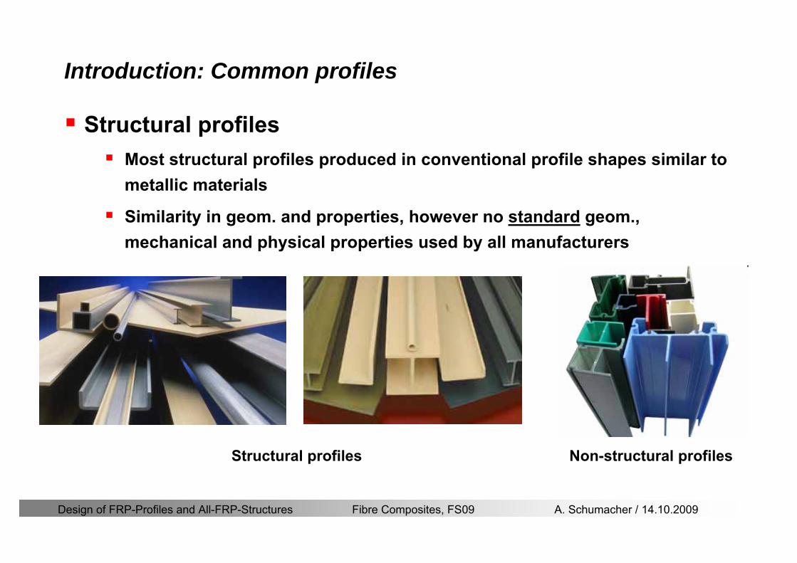
Design of FRP-Profiles and All-FRP-Structures Fibre Composites FS09 A Schumacher 14102009
Introduction Common profiles
Structural profilesMost structural profiles produced in conventional profile shapes similar to metallic materials
Similarity in geom and properties however no standard geom mechanical and physical properties used by all manufacturers
Structural profiles Non-structural profiles
Design of FRP-Profiles and All-FRP-Structures Fibre Composites FS09 A Schumacher 14102009
Introduction Examples
Footbridges
Fiberline Bridge in Kolding DK
Span 40 mCost 05 mio CHFOnly Fiberline standard profiles used
httpwwwfiberlinecomgbcasestoriescase1837asp
Pontresina bridge Switzerland
Span 2 x 125 mWeight 33 tons (installation by helicopter)
httpwwwfiberlinecomgbcasestoriescase1830asp
Design of FRP-Profiles and All-FRP-Structures Fibre Composites FS09 A Schumacher 14102009
Introduction Examples
Footbridges
Composite pedestrian bridge in Lleida Spain
Span 38 mWidth 30 m
httpwwwfiberlinecomgbcasestoriescase2828asp
Design of FRP-Profiles and All-FRP-Structures Fibre Composites FS09 A Schumacher 14102009
Introduction Examples (ASSET Profile)
Road bridges
West Mill Bridge England
Span 10 mWidth 68 mLoad capacity 46 tons
httpwwwfiberlinecomgbcasestoriescase3903asp
Klipphausen Bridge Germany
Span 68 mWidth 60 mLoad capacity 40 tons
httpwwwfiberlinecomgbcasestoriescase6314asp
Design of FRP-Profiles and All-FRP-Structures Fibre Composites FS09 A Schumacher 14102009
Introduction Examples
Bridgedeck (Footbridges)Wuumlrenlos Switzerland Loopersteg Switzerland
Design of FRP-Profiles and All-FRP-Structures Fibre Composites FS09 A Schumacher 14102009
Introduction Examples
Buildings
Eyecatcher Building Basel Switzerland
Height 15 mStoreys 5
httpwwwfiberlinecomgbcasestoriescase1835asp
Project Maagtechnic
Design of FRP-Profiles and All-FRP-Structures Fibre Composites FS09 A Schumacher 14102009
Introduction Examples
Laboratory bridgeEmpa Laboratory Bridge Switzerland
Span 19 mWidth 16 mLoad capacity 15 tons
Design of FRP-Profiles and All-FRP-Structures Fibre Composites FS09 A Schumacher 14102009
Introduction Examples
Noise barrier SBB
Goumlschenen Switzerland
Project Maagtechnic
Design of FRP-Profiles and All-FRP-Structures Fibre Composites FS09 A Schumacher 14102009
Introduction Examples
Balconies
Switzerland
Project Maagtechnic
Design of FRP-Profiles and All-FRP-Structures Fibre Composites FS09 A Schumacher 14102009
Introduction Examples
RailingsOensingen Switzerland
Heineken brewery Switzerland
Design of FRP-Profiles and All-FRP-Structures Fibre Composites FS09 A Schumacher 14102009
Introduction Application
Applications where GFRP structures are competitive
Significant corrosion and chemical resistance is required(Food and chemical processing plants cooling towers offshore platforms hellip)
Electromagnetic transparency or electrical insulation is required
Light-weight is cost essential(fast deployment hellip)
Prestige and demonstration objects (eg Novartis Campus Entrance Building)
Photo Prof Th Keller EPFL
Design of FRP-Profiles and All-FRP-Structures Fibre Composites FS09 A Schumacher 14102009
Material
Design of FRP-Profiles and All-FRP-Structures Fibre Composites FS09 A Schumacher 14102009
Only pultruded GFRP profiles will be considered in this lecture
Production of profiles with constant cross-section along the length
High quality
Continuous longitudinal fiber bundles and filament mats
Pultrusion line
Material Pultrusion process
Design of FRP-Profiles and All-FRP-Structures Fibre Composites FS09 A Schumacher 14102009
Material Components
Pultruded profiles contain three primary componentsreinforcement
Matrix
Supplementaryconstituents
polyesterepoxyphenol
polymerisation agentsfillersadditives
Design of FRP-Profiles and All-FRP-Structures Fibre Composites FS09 A Schumacher 14102009
Material Shapes of pultruded profiles
Available Profiles on Stock
Length up to 12 m
Special cross-sections can be designed and ordered(several kilometres are necessary rarr special tools have to be designed)
Design of FRP-Profiles and All-FRP-Structures Fibre Composites FS09 A Schumacher 14102009
Material Durability
Various environmental and load conditions that affect durability of (G)FRPs in terms of strength stiffness fibermatrix interface integrity cracking
watersea waterchemical solutionsprolonged freezingthermal cycling (freeze-thaw)elevated temperature exposureUV radiationcreep and relaxationfatiguefirehellip
Design of FRP-Profiles and All-FRP-Structures Fibre Composites FS09 A Schumacher 14102009
Material Durability
Environmental reduction factor for different FRP systems and exposure conditions
070Aramidepoxy
050Glassepoxy(chemical plants)
085CarbonepoxyAgressive environ
075Aramidepoxyparking garages)
065Glassepoxy(bridges piers
085CarbonepoxyExterior exposure
085Aramidepoxy
075Glassepoxy
095CarbonepoxyInterior exposure
Environ reductionFiber resin typeExposure condition
Design of FRP-Profiles and All-FRP-Structures Fibre Composites FS09 A Schumacher 14102009
Material Durability
GFRP is more susceptible to degradation than CFRP by the following effects
alkaline effects (caution when GFRP in contact with concrete)acid effectssalt effectsfatigueUV radiation
Fire protection is a major (unsolved) issue for (G)FRP structural elements and components
Smoke generation and toxicity must be consideredStrength of GFRP is affected by fatigue loading(more than CFRP)
Design of FRP-Profiles and All-FRP-Structures Fibre Composites FS09 A Schumacher 14102009
Material Manufacturers
GFRP profiles available on stock
In Europe two companies pultrude FRP-Profiles
Fiberline Composites Denmarkwwwfiberlinecom
Fiberline Design Manual (wwwfiberlinedk)rarr helpful tool to design structures
(material properties geometries connections hellip)
Top Glass Italywwwtopglassit
Design of FRP-Profiles and All-FRP-Structures Fibre Composites FS09 A Schumacher 14102009
Material Manufacturers
GFRP profiles available on stock
In North America
Strongwell USAwwwstrongwellcom
Creative Pultrusions USAwwwcreativepultrusionscom
Bedford Reinforced Plastics USAwwwbedfordplasticscom
Design of FRP-Profiles and All-FRP-Structures Fibre Composites FS09 A Schumacher 14102009
Design Concept
Design of FRP-Profiles and All-FRP-Structures Fibre Composites FS09 A Schumacher 14102009
Design Concept Basic Assumptions
Definitions and directions
Design of FRP-Profiles and All-FRP-Structures Fibre Composites FS09 A Schumacher 14102009
Design Concept
Codes
Every manufacturer has its own profile design rarr No European Design Code is available (only EN13706 about testing and notation)
There exists European guidelines EUROCOMP 1996 Design CodeEUROCOMP 1996 Handbook
Fiberline Design Manual is based on Eurocomp 1996
Design concept (according to Eurocodes and Swisscodes)
Partial safety factors
Measured material parameters
Rules for bolted connections
Design of FRP-Profiles and All-FRP-Structures Fibre Composites FS09 A Schumacher 14102009
Design Concept
Concept of Limit State Design (According to Euro Codes and Swiss Codes)
Ultimate limit stress
Ed le Rd
Ed hellip Calculated stress (including load factors) hellip SIA260 261
Rd hellip Rated value of the resistance capability
where
Rk hellip the calculated resistance capability
kd mγ=
RR
Design of FRP-Profiles and All-FRP-Structures Fibre Composites FS09 A Schumacher 14102009
101020Production process
Operating temperature
111116Degree of postcuring
115115225Derivation of mat properties
FiberlineMinMaxDescriptionCoefficient
Design Concept
Reduction coefficient m m1 m2 m3 m4γ γ γ γ γ= sdot sdot sdot
m1γ
m2γ
m3γ
m4γ
mγ mγ
31312580
2510-20 +60
Long-term loadShort-term load
Operatingtemperature degC m4γ
Design of FRP-Profiles and All-FRP-Structures Fibre Composites FS09 A Schumacher 14102009
Design Concept
Serviceability limit states
Ed le Cd
Ed hellip the crucial action effect due to the load cases considered inthe investigated dimensioning situation Typically maximaldeflection response of the structure
Cd hellip corresponding serviceability limit SIA 261
Design of FRP-Profiles and All-FRP-Structures Fibre Composites FS09 A Schumacher 14102009
Design Concept Basic Assumptions
Material Properties stength values (Fiberline Profiles)
Design of FRP-Profiles and All-FRP-Structures Fibre Composites FS09 A Schumacher 14102009
Design Concept Basic Assumptions
Material Properties stiffness values (Fiberline Profiles)
Design of FRP-Profiles and All-FRP-Structures Fibre Composites FS09 A Schumacher 14102009
Design Concept Basic Assumptions
Typical data sheet of a profile (Fiberline I-Profile)
Design of FRP-Profiles and All-FRP-Structures Fibre Composites FS09 A Schumacher 14102009
Bending Beam
Design of FRP-Profiles and All-FRP-Structures Fibre Composites FS09 A Schumacher 14102009
Bending Beam Design of hellip
Calculate bending moments Md and shear forces Qd acting on the profile using the partial coefficient (SIA 260 261)
Ultimate limit state
Bending
Shear
Ak hellip relevant shear area
d max d max 0max
M MW Wy z b
mzy
fσ γ
⎛ ⎞⎜ ⎟⎜ ⎟⎜ ⎟⎜ ⎟⎝ ⎠
deg= + le
d maxmax
kyAy
m
Q fττ γ= le
Design of FRP-Profiles and All-FRP-Structures Fibre Composites FS09 A Schumacher 14102009
Bending Beam Design of hellip
Serviceability limit state
Deflection limit
hellip typically selected between 200 and 400given by SIA 261 or the building owner
hellip calculated including shear deformations
Vibrations
Light-weighted and lsquosoftrsquo structures are susceptible to vibrations (traffic wind the movement of people hellip)
max 1wL αlt
α
maxw
Design of FRP-Profiles and All-FRP-Structures Fibre Composites FS09 A Schumacher 14102009
Bending Beam Timoshenko Theory
Pultruded profiles have a low shear modulus rarr shear deformation must be taken into account
Several bending theories have been published for beams
Euler-Bernoulli theory (1702)
Timoshenko theory (1968)
Higher order beam theory
A simply supported beam with a symmetric cross-section is discussed
Design of FRP-Profiles and All-FRP-Structures Fibre Composites FS09 A Schumacher 14102009
Bending Beam Timoshenko Theory
Cross-sections planeand perpendicular
1 degree of freedom
w
Cross-sections plane butNOT perpendicular
2 degrees of freedom
w and ψ
Cross-sections do NOTremain plane
3+ degrees of freedom
w ψ and hellip
Design of FRP-Profiles and All-FRP-Structures Fibre Composites FS09 A Schumacher 14102009
Bending Beam Euler vs Timoshenko Theory
Kinematic relationships
( )( )
( )
2 0
x x
y
xx xx
yxxy
u y w xu w x
u y w xxuu
y x
ε
ε
=minus sdot=
part= =minus sdotpartpartpart= + =
part part
( )( )
( )
2 ( ) ( )
x
y
xx x
yxxy x
u y xu w x
u y xxuu x w xy x
ψ
ε ψ
ε ψ
=minus sdot=
part= =minus sdotpartpartpart= + =minus +
part part
Hookrsquos law
0degE and G 2x x xy xyσ ε τ ε= sdot = sdot
z0deg E Iz x xxQS
M y dydz wσ= minus sdot sdot = sdot sdotintint
( )
z0deg E I
z x xQS
y xQS
M y dydz
Q dydz w GA
σ ψ
κ τ ψ κ
= minus sdot sdot = sdot
= sdot = minus sdot sdot
intint
intint
Design of FRP-Profiles and All-FRP-Structures Fibre Composites FS09 A Schumacher 14102009
Bending Beam Euler vs Timoshenko Theory
Equilibrium
Solution for the simply supported beam (distributed load)
In a first approximation the deflections are calculated by direct integration of
z0deg
( ) E IxxM xw = sdot
( )( )z0deg
( ) E I 0x
x
xx x
xx x
q x w GAw GA
QM Q
ψ κψ ψ κ
minus minus sdot sdot
sdot + minus sdot sdot
=minus =
= =minus
Equilibrium on an infinitesimal beam element
Coupled second order differential equation
21 1( ) (0) 0 and ( ) 02 2
M x qLx qx w w L= minus = =
( )3 2 3
0deg z
( ) 224 E Iqxw x L Lx x= sdot minus +sdot sdot
2
0deg z
1 1 1E I 2 2xxw qLx qx⎛ ⎞= minus⎜ ⎟sdot ⎝ ⎠
(0) 0 and ( ) 0(0) 0 (0) 0 and ( ) 0 ( ) 0 x x
w w LM M L Lψ ψ
= == rarr = = rarr =
Functions4 3 2
1 2 3 4 53 2
1 2 3 4
( )
( )
w x A x A x A x A x A
x B x B x B x Bψ
= + + + +
= + + +
Design of FRP-Profiles and All-FRP-Structures Fibre Composites FS09 A Schumacher 14102009
Put in and solve for the coefficients rarr
Bending Beam Euler vs Timoshenko Theory
Use the boundary conditions and the second differential eq to calculate A1 ndash A5
( )0deg z E I 0xx xw GAψ ψ κsdot + minus sdot sdot =
1 01 1 3 3
2 02 2 4 4
24 E I4 2GA
6 E I3 GA
z
z
AB A B A
AB A B A
κ
κ
deg
deg
sdot= minus = minus minus
sdotsdot
= minus = minus minussdot
( ) ( )( )2 2
0
( )2 GA 24 E Iz
qx L x L Lx xqx L xw x
κ deg
minus + minusminus= +
sdot sdot sdot
Deflection at midspan
4
0
52 384 E Iz
qLLw⎛ ⎞⎜ ⎟⎝ ⎠
deg
sdot= sdot4 2
0
52 384 E I 8 GAz
qL q LLw κ⎛ ⎞ +⎜ ⎟⎝ ⎠
deg
sdot sdot= sdot sdot sdot
Design of FRP-Profiles and All-FRP-Structures Fibre Composites FS09 A Schumacher 14102009
General expression for the total beam deflection as a sum of the deflection due to bending and shear
GAxf
IExfxwz sdot+=
deg κ)()()( 2
0
1
Cantilever beam
Simply supported
Concentrated load (P)
Uniformly distr load (q)
Concentrated load (P)
Uniformly distr load (q)
Beam )( max1 wf
3845 4qLsdot
48
3PL
8
4qL
3
3PL
)( max1 wf
8
2qL
4PL
2
2qL
PL
)( maxwx
2L
2L
L
L
Bending Beam Euler vs Timoshenko Theory
Design of FRP-Profiles and All-FRP-Structures Fibre Composites FS09 A Schumacher 14102009
Bending Beam Euler vs Timoshenko Theory
Example influence of the shear deformation
Profile 300 x 150 mm I-beam
Load uniformly distributed
General rule of thumbfor GFRP beams withspandepth gt 25 sheardeformation can beignored
Design of FRP-Profiles and All-FRP-Structures Fibre Composites FS09 A Schumacher 14102009
Bending Beam Example
Choose an appropriate Profile for the following specifications
1 Deflections and loading
=
=
==
1300 rarr wmax=001 mwmaxL
10 kNmqdser
13 kNmqduls
30 mL
max
4 2
0
5384 E I 8 GA
d ser d serz
q L q Lw κ+
deg
sdot sdot= sdot sdot sdot
2
maxz8 2 I
d ulsq L hσ sdot= sdot
maxky
12 Ad ulsq L
τ sdot=
Design of FRP-Profiles and All-FRP-Structures Fibre Composites FS09 A Schumacher 14102009
Bending Beam Example
2 Find a profile with sufficient bending stiffness
Shear deformations are neglected in a first step
rarr from specification table choose I 240x120x12 rarr
3 Check the bending and shear stresses
6 24
0 max
1054 10 Nm5
E I 384d ser
zq Lwdeg = sdot
sdotsdotge
6 20 1369 10 NmE Izdeg = sdot
2
maxz
358 MPa8 2 Id ulsq L hσ sdot= =sdot
max
ky
1 71 MPa2 Ad ulsq L
τ sdot= =
0 185 MPab df degle =
20 MPadfτle =
Design of FRP-Profiles and All-FRP-Structures Fibre Composites FS09 A Schumacher 14102009
Bending Beam Example
m10398384
5 32
0
4
maxminus
deg
sdot=sdotsdotsdot
+sdot
sdot=
GALq
IELq
w serd
z
serd
κ
4 Check deflection (including shear deformation)
5 Remarks
The design of GFRP-profiles is mostly driven by serviceability criteria
Start the design iteration procedure using the maximal deflection criterion
max 001 mwle =
m10198384
5 32
0
4
maxminus
deg
sdot=sdot
sdot+
sdotsdot
=web
serd
z
serd
GALq
IELq
w
(77 mm) (16 mm)
Design of FRP-Profiles and All-FRP-Structures Fibre Composites FS09 A Schumacher 14102009
Bending Beam Stability problems
Lateral-torsional bucklingFlange (compressive) displace laterally to the transverse load direction
Torsional stiffness is too low (especially for open section profiles)
Theoretical calculations or design measuresrarr see eg LP Kollaacuter 2003
Mechanics of composite structuresExample
Compressive flanges are kept in place by connection to the bridge deck
Design of FRP-Profiles and All-FRP-Structures Fibre Composites FS09 A Schumacher 14102009
Bending Beam Stability problems
Flange (compressive) displaces in the direction of the transverse load
Low bending stiffness perpendicular to the pultrusion direction
Weak fiber mats
Local buckling of walls due to in-plane compression
Local buckling of walls due to in-plane shear
Web crushing and web buckling in transverse direction
Design of FRP-Profiles and All-FRP-Structures Fibre Composites FS09 A Schumacher 14102009
Axial Members
Design of FRP-Profiles and All-FRP-Structures Fibre Composites FS09 A Schumacher 14102009
Axial Members Tension
Ultimate limit state under axial tension Nd
Serviceability limit state
Remark The critical aspect of axial members in tension are neither the serviceability nor the ultimate limit state Critical is the load transfer to the GFRP profile
0NdA
tm
fγ
degle
0deg
N LE Axδ sdot= sdot
Design of FRP-Profiles and All-FRP-Structures Fibre Composites FS09 A Schumacher 14102009
Axial Members Compression
Ultimate limit state under axial compression Nd
hellip maximal compressive load
hellip Euler load
hellip Buckling length for columns
hellip coefficient for Youngrsquos modulus = 13
cc
Euler
FNd F1 N
le+
c0degC
A fF
mγsdot
=
20
Euler 2
Nm E k
E IL
πγ
degsdot sdot=
sdot
kL
m Eγ
Design of FRP-Profiles and All-FRP-Structures Fibre Composites FS09 A Schumacher 14102009
Axial Members Compression
The influence of shear deformation should be considered but in the most cases the influence will be small (less than 5)
Local buckling should be considered for short columns
For more information on the various buckling modes and effects rarr see LP Kollaacuter 2003 Mechanics of composite structures
Global buckling Local buckling
Design of FRP-Profiles and All-FRP-Structures Fibre Composites FS09 A Schumacher 14102009
Connections
Design of FRP-Profiles and All-FRP-Structures Fibre Composites FS09 A Schumacher 14102009
Connections Introduction
Design of FRP-Profiles and All-FRP-Structures Fibre Composites FS09 A Schumacher 14102009
Connections Introduction
(from Eurocomp Design Code 1996)
Design of FRP-Profiles and All-FRP-Structures Fibre Composites FS09 A Schumacher 14102009
Connections Bolted joints
Bolts = Stress concentration in the profile and the bolt
It is necessary to ensure that the bolts and the profilecan withstand this concentrated local stress compression
It is necessary to ensure that the region surroundinga group of bolts will not be torn out of the profile
Basic failure modesin bolted shearconnections
bolt shear failure
Design of FRP-Profiles and All-FRP-Structures Fibre Composites FS09 A Schumacher 14102009
Connections Bolted joints
The design procedure is comparable to the one for steel connections but since there exist no standard GFRP material rarr each manufacturer has its own design rules for bolted joints
IMPORTANT REMARKS
The direction of pultrusion and the direction of the force is RELEVANT(anisotropic material)
Use stainless or galvanised steel
Do not cut threads in the composite material
Use screws with shafts
Design of FRP-Profiles and All-FRP-Structures Fibre Composites FS09 A Schumacher 14102009
Calculation of load bearing capacity of bolts
Shear in longitudinal direction (0deg)
Shear in transverse direction (90deg)
Tensile force
Minimum distances
Connections Bolted joints (Fiberline recommendations)
Design of FRP-Profiles and All-FRP-Structures Fibre Composites FS09 A Schumacher 14102009
Joint capacity tables available for shear and tension
m
150 MPa( 13)B d
d tP γsdot sdot=
=
Shear in longitudinal direction 0deg
m
70 MPa( 13)B d
d tP γsdot sdot=
=
Shear in transverse direction 90deg
Connections Bolted joints (Fiberline recommendations)
Design of FRP-Profiles and All-FRP-Structures Fibre Composites FS09 A Schumacher 14102009
Bolted connection in shear eg shear in longitudinal direction
Connections Bolted joints (Fiberline recommendations)
γmPBolt le dt720 MPaγmPBolt le dt240 MPa
γmPBolt le dt240 MPa γmPBolt le dt240 MPaγmPBolt le dt150 MPa
Design of FRP-Profiles and All-FRP-Structures Fibre Composites FS09 A Schumacher 14102009
Bolted connections in tension
Static conditions
Bolt Tearing of bolt in threaded cross-section
Laminate Shear fracture at rim of washer
Geometry and strength
Diameter of washer2d
Tensile strength of bolt hellipfyk
Shear strength of laminatehellipfτ
Thickness of laminatet
Stress area of the boltAs
Diameter of the boltd
s ykd m
A fP γ
sdotle
2d m
d t fP τπγ
sdot sdot sdot sdotle
Connections Bolted joints (Fiberline recommendations)
Design of FRP-Profiles and All-FRP-Structures Fibre Composites FS09 A Schumacher 14102009
Connections Bonded joints
Using an adhesive agent for joining profiles can have advantages
Easy to use easy to make aesthetic joints
Typically more rigid than bolted joints
Glued joints subjected to dynamic loads are good
But be careful hellipAdhesive agents have properties that depend on time temperature humidity hellip
Failure in glued joints takes place suddenly (brittle behaviour)
The load-bearing capacity is not proportional to the area which is glued
The design of bonded joints may be based onAnalytical models for plate-to-plate connections (see Eurocomp 1996 Design Code)
Design guidelines supplemented by testing
Finite element analysis
Design of FRP-Profiles and All-FRP-Structures Fibre Composites FS09 A Schumacher 14102009
Connections Bonded joints
A bonded joint has the following three primary failure modes
adhesive failure
cohesive failure of adhesive
cohesive failure of adherend
The design of any bonded joint shall satisfy the following conditions
allowable shear stress in the adhesive is not exceeded
allowable tensile (peel) stress in the adhesive is not exceeded
allowable through-thickness tensile stress of the adhesive is not exceeded
allowable in-plane shear stress of the adherend should not be exceeded
The calculation of the stresses has to be done very carefully Often calculations are supplemented by testing
Design of FRP-Profiles and All-FRP-Structures Fibre Composites FS09 A Schumacher 14102009
Connections Bonded joints
Different types of bonded joint configurations
Research on bonded joints for structuralapplications
Design of FRP-Profiles and All-FRP-Structures Fibre Composites FS09 A Schumacher 14102009
Connections Other joints
Brackets for assembly (Fiberline)
Custom pultruded connections
Design of FRP-Profiles and All-FRP-Structures Fibre Composites FS09 A Schumacher 14102009
GFRP Some final remarks
Perpendicular to the direction of pultrusion the material is WEAK and SOFTrarr avoid such loadings if possible
In order to use pultruded GFRP-profiles economically the design must be done in a clever way eg for bridges the railings should be used as part of the load-bearing structure
GFRP structures are very light rarr vibration problems may occur
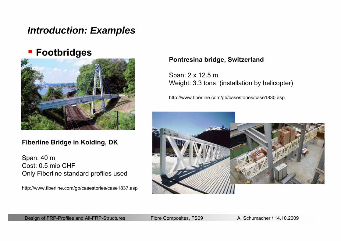
Design of FRP-Profiles and All-FRP-Structures Fibre Composites FS09 A Schumacher 14102009
Introduction Examples
Footbridges
Fiberline Bridge in Kolding DK
Span 40 mCost 05 mio CHFOnly Fiberline standard profiles used
httpwwwfiberlinecomgbcasestoriescase1837asp
Pontresina bridge Switzerland
Span 2 x 125 mWeight 33 tons (installation by helicopter)
httpwwwfiberlinecomgbcasestoriescase1830asp
Design of FRP-Profiles and All-FRP-Structures Fibre Composites FS09 A Schumacher 14102009
Introduction Examples
Footbridges
Composite pedestrian bridge in Lleida Spain
Span 38 mWidth 30 m
httpwwwfiberlinecomgbcasestoriescase2828asp
Design of FRP-Profiles and All-FRP-Structures Fibre Composites FS09 A Schumacher 14102009
Introduction Examples (ASSET Profile)
Road bridges
West Mill Bridge England
Span 10 mWidth 68 mLoad capacity 46 tons
httpwwwfiberlinecomgbcasestoriescase3903asp
Klipphausen Bridge Germany
Span 68 mWidth 60 mLoad capacity 40 tons
httpwwwfiberlinecomgbcasestoriescase6314asp
Design of FRP-Profiles and All-FRP-Structures Fibre Composites FS09 A Schumacher 14102009
Introduction Examples
Bridgedeck (Footbridges)Wuumlrenlos Switzerland Loopersteg Switzerland
Design of FRP-Profiles and All-FRP-Structures Fibre Composites FS09 A Schumacher 14102009
Introduction Examples
Buildings
Eyecatcher Building Basel Switzerland
Height 15 mStoreys 5
httpwwwfiberlinecomgbcasestoriescase1835asp
Project Maagtechnic
Design of FRP-Profiles and All-FRP-Structures Fibre Composites FS09 A Schumacher 14102009
Introduction Examples
Laboratory bridgeEmpa Laboratory Bridge Switzerland
Span 19 mWidth 16 mLoad capacity 15 tons
Design of FRP-Profiles and All-FRP-Structures Fibre Composites FS09 A Schumacher 14102009
Introduction Examples
Noise barrier SBB
Goumlschenen Switzerland
Project Maagtechnic
Design of FRP-Profiles and All-FRP-Structures Fibre Composites FS09 A Schumacher 14102009
Introduction Examples
Balconies
Switzerland
Project Maagtechnic
Design of FRP-Profiles and All-FRP-Structures Fibre Composites FS09 A Schumacher 14102009
Introduction Examples
RailingsOensingen Switzerland
Heineken brewery Switzerland
Design of FRP-Profiles and All-FRP-Structures Fibre Composites FS09 A Schumacher 14102009
Introduction Application
Applications where GFRP structures are competitive
Significant corrosion and chemical resistance is required(Food and chemical processing plants cooling towers offshore platforms hellip)
Electromagnetic transparency or electrical insulation is required
Light-weight is cost essential(fast deployment hellip)
Prestige and demonstration objects (eg Novartis Campus Entrance Building)
Photo Prof Th Keller EPFL
Design of FRP-Profiles and All-FRP-Structures Fibre Composites FS09 A Schumacher 14102009
Material
Design of FRP-Profiles and All-FRP-Structures Fibre Composites FS09 A Schumacher 14102009
Only pultruded GFRP profiles will be considered in this lecture
Production of profiles with constant cross-section along the length
High quality
Continuous longitudinal fiber bundles and filament mats
Pultrusion line
Material Pultrusion process
Design of FRP-Profiles and All-FRP-Structures Fibre Composites FS09 A Schumacher 14102009
Material Components
Pultruded profiles contain three primary componentsreinforcement
Matrix
Supplementaryconstituents
polyesterepoxyphenol
polymerisation agentsfillersadditives
Design of FRP-Profiles and All-FRP-Structures Fibre Composites FS09 A Schumacher 14102009
Material Shapes of pultruded profiles
Available Profiles on Stock
Length up to 12 m
Special cross-sections can be designed and ordered(several kilometres are necessary rarr special tools have to be designed)
Design of FRP-Profiles and All-FRP-Structures Fibre Composites FS09 A Schumacher 14102009
Material Durability
Various environmental and load conditions that affect durability of (G)FRPs in terms of strength stiffness fibermatrix interface integrity cracking
watersea waterchemical solutionsprolonged freezingthermal cycling (freeze-thaw)elevated temperature exposureUV radiationcreep and relaxationfatiguefirehellip
Design of FRP-Profiles and All-FRP-Structures Fibre Composites FS09 A Schumacher 14102009
Material Durability
Environmental reduction factor for different FRP systems and exposure conditions
070Aramidepoxy
050Glassepoxy(chemical plants)
085CarbonepoxyAgressive environ
075Aramidepoxyparking garages)
065Glassepoxy(bridges piers
085CarbonepoxyExterior exposure
085Aramidepoxy
075Glassepoxy
095CarbonepoxyInterior exposure
Environ reductionFiber resin typeExposure condition
Design of FRP-Profiles and All-FRP-Structures Fibre Composites FS09 A Schumacher 14102009
Material Durability
GFRP is more susceptible to degradation than CFRP by the following effects
alkaline effects (caution when GFRP in contact with concrete)acid effectssalt effectsfatigueUV radiation
Fire protection is a major (unsolved) issue for (G)FRP structural elements and components
Smoke generation and toxicity must be consideredStrength of GFRP is affected by fatigue loading(more than CFRP)
Design of FRP-Profiles and All-FRP-Structures Fibre Composites FS09 A Schumacher 14102009
Material Manufacturers
GFRP profiles available on stock
In Europe two companies pultrude FRP-Profiles
Fiberline Composites Denmarkwwwfiberlinecom
Fiberline Design Manual (wwwfiberlinedk)rarr helpful tool to design structures
(material properties geometries connections hellip)
Top Glass Italywwwtopglassit
Design of FRP-Profiles and All-FRP-Structures Fibre Composites FS09 A Schumacher 14102009
Material Manufacturers
GFRP profiles available on stock
In North America
Strongwell USAwwwstrongwellcom
Creative Pultrusions USAwwwcreativepultrusionscom
Bedford Reinforced Plastics USAwwwbedfordplasticscom
Design of FRP-Profiles and All-FRP-Structures Fibre Composites FS09 A Schumacher 14102009
Design Concept
Design of FRP-Profiles and All-FRP-Structures Fibre Composites FS09 A Schumacher 14102009
Design Concept Basic Assumptions
Definitions and directions
Design of FRP-Profiles and All-FRP-Structures Fibre Composites FS09 A Schumacher 14102009
Design Concept
Codes
Every manufacturer has its own profile design rarr No European Design Code is available (only EN13706 about testing and notation)
There exists European guidelines EUROCOMP 1996 Design CodeEUROCOMP 1996 Handbook
Fiberline Design Manual is based on Eurocomp 1996
Design concept (according to Eurocodes and Swisscodes)
Partial safety factors
Measured material parameters
Rules for bolted connections
Design of FRP-Profiles and All-FRP-Structures Fibre Composites FS09 A Schumacher 14102009
Design Concept
Concept of Limit State Design (According to Euro Codes and Swiss Codes)
Ultimate limit stress
Ed le Rd
Ed hellip Calculated stress (including load factors) hellip SIA260 261
Rd hellip Rated value of the resistance capability
where
Rk hellip the calculated resistance capability
kd mγ=
RR
Design of FRP-Profiles and All-FRP-Structures Fibre Composites FS09 A Schumacher 14102009
101020Production process
Operating temperature
111116Degree of postcuring
115115225Derivation of mat properties
FiberlineMinMaxDescriptionCoefficient
Design Concept
Reduction coefficient m m1 m2 m3 m4γ γ γ γ γ= sdot sdot sdot
m1γ
m2γ
m3γ
m4γ
mγ mγ
31312580
2510-20 +60
Long-term loadShort-term load
Operatingtemperature degC m4γ
Design of FRP-Profiles and All-FRP-Structures Fibre Composites FS09 A Schumacher 14102009
Design Concept
Serviceability limit states
Ed le Cd
Ed hellip the crucial action effect due to the load cases considered inthe investigated dimensioning situation Typically maximaldeflection response of the structure
Cd hellip corresponding serviceability limit SIA 261
Design of FRP-Profiles and All-FRP-Structures Fibre Composites FS09 A Schumacher 14102009
Design Concept Basic Assumptions
Material Properties stength values (Fiberline Profiles)
Design of FRP-Profiles and All-FRP-Structures Fibre Composites FS09 A Schumacher 14102009
Design Concept Basic Assumptions
Material Properties stiffness values (Fiberline Profiles)
Design of FRP-Profiles and All-FRP-Structures Fibre Composites FS09 A Schumacher 14102009
Design Concept Basic Assumptions
Typical data sheet of a profile (Fiberline I-Profile)
Design of FRP-Profiles and All-FRP-Structures Fibre Composites FS09 A Schumacher 14102009
Bending Beam
Design of FRP-Profiles and All-FRP-Structures Fibre Composites FS09 A Schumacher 14102009
Bending Beam Design of hellip
Calculate bending moments Md and shear forces Qd acting on the profile using the partial coefficient (SIA 260 261)
Ultimate limit state
Bending
Shear
Ak hellip relevant shear area
d max d max 0max
M MW Wy z b
mzy
fσ γ
⎛ ⎞⎜ ⎟⎜ ⎟⎜ ⎟⎜ ⎟⎝ ⎠
deg= + le
d maxmax
kyAy
m
Q fττ γ= le
Design of FRP-Profiles and All-FRP-Structures Fibre Composites FS09 A Schumacher 14102009
Bending Beam Design of hellip
Serviceability limit state
Deflection limit
hellip typically selected between 200 and 400given by SIA 261 or the building owner
hellip calculated including shear deformations
Vibrations
Light-weighted and lsquosoftrsquo structures are susceptible to vibrations (traffic wind the movement of people hellip)
max 1wL αlt
α
maxw
Design of FRP-Profiles and All-FRP-Structures Fibre Composites FS09 A Schumacher 14102009
Bending Beam Timoshenko Theory
Pultruded profiles have a low shear modulus rarr shear deformation must be taken into account
Several bending theories have been published for beams
Euler-Bernoulli theory (1702)
Timoshenko theory (1968)
Higher order beam theory
A simply supported beam with a symmetric cross-section is discussed
Design of FRP-Profiles and All-FRP-Structures Fibre Composites FS09 A Schumacher 14102009
Bending Beam Timoshenko Theory
Cross-sections planeand perpendicular
1 degree of freedom
w
Cross-sections plane butNOT perpendicular
2 degrees of freedom
w and ψ
Cross-sections do NOTremain plane
3+ degrees of freedom
w ψ and hellip
Design of FRP-Profiles and All-FRP-Structures Fibre Composites FS09 A Schumacher 14102009
Bending Beam Euler vs Timoshenko Theory
Kinematic relationships
( )( )
( )
2 0
x x
y
xx xx
yxxy
u y w xu w x
u y w xxuu
y x
ε
ε
=minus sdot=
part= =minus sdotpartpartpart= + =
part part
( )( )
( )
2 ( ) ( )
x
y
xx x
yxxy x
u y xu w x
u y xxuu x w xy x
ψ
ε ψ
ε ψ
=minus sdot=
part= =minus sdotpartpartpart= + =minus +
part part
Hookrsquos law
0degE and G 2x x xy xyσ ε τ ε= sdot = sdot
z0deg E Iz x xxQS
M y dydz wσ= minus sdot sdot = sdot sdotintint
( )
z0deg E I
z x xQS
y xQS
M y dydz
Q dydz w GA
σ ψ
κ τ ψ κ
= minus sdot sdot = sdot
= sdot = minus sdot sdot
intint
intint
Design of FRP-Profiles and All-FRP-Structures Fibre Composites FS09 A Schumacher 14102009
Bending Beam Euler vs Timoshenko Theory
Equilibrium
Solution for the simply supported beam (distributed load)
In a first approximation the deflections are calculated by direct integration of
z0deg
( ) E IxxM xw = sdot
( )( )z0deg
( ) E I 0x
x
xx x
xx x
q x w GAw GA
QM Q
ψ κψ ψ κ
minus minus sdot sdot
sdot + minus sdot sdot
=minus =
= =minus
Equilibrium on an infinitesimal beam element
Coupled second order differential equation
21 1( ) (0) 0 and ( ) 02 2
M x qLx qx w w L= minus = =
( )3 2 3
0deg z
( ) 224 E Iqxw x L Lx x= sdot minus +sdot sdot
2
0deg z
1 1 1E I 2 2xxw qLx qx⎛ ⎞= minus⎜ ⎟sdot ⎝ ⎠
(0) 0 and ( ) 0(0) 0 (0) 0 and ( ) 0 ( ) 0 x x
w w LM M L Lψ ψ
= == rarr = = rarr =
Functions4 3 2
1 2 3 4 53 2
1 2 3 4
( )
( )
w x A x A x A x A x A
x B x B x B x Bψ
= + + + +
= + + +
Design of FRP-Profiles and All-FRP-Structures Fibre Composites FS09 A Schumacher 14102009
Put in and solve for the coefficients rarr
Bending Beam Euler vs Timoshenko Theory
Use the boundary conditions and the second differential eq to calculate A1 ndash A5
( )0deg z E I 0xx xw GAψ ψ κsdot + minus sdot sdot =
1 01 1 3 3
2 02 2 4 4
24 E I4 2GA
6 E I3 GA
z
z
AB A B A
AB A B A
κ
κ
deg
deg
sdot= minus = minus minus
sdotsdot
= minus = minus minussdot
( ) ( )( )2 2
0
( )2 GA 24 E Iz
qx L x L Lx xqx L xw x
κ deg
minus + minusminus= +
sdot sdot sdot
Deflection at midspan
4
0
52 384 E Iz
qLLw⎛ ⎞⎜ ⎟⎝ ⎠
deg
sdot= sdot4 2
0
52 384 E I 8 GAz
qL q LLw κ⎛ ⎞ +⎜ ⎟⎝ ⎠
deg
sdot sdot= sdot sdot sdot
Design of FRP-Profiles and All-FRP-Structures Fibre Composites FS09 A Schumacher 14102009
General expression for the total beam deflection as a sum of the deflection due to bending and shear
GAxf
IExfxwz sdot+=
deg κ)()()( 2
0
1
Cantilever beam
Simply supported
Concentrated load (P)
Uniformly distr load (q)
Concentrated load (P)
Uniformly distr load (q)
Beam )( max1 wf
3845 4qLsdot
48
3PL
8
4qL
3
3PL
)( max1 wf
8
2qL
4PL
2
2qL
PL
)( maxwx
2L
2L
L
L
Bending Beam Euler vs Timoshenko Theory
Design of FRP-Profiles and All-FRP-Structures Fibre Composites FS09 A Schumacher 14102009
Bending Beam Euler vs Timoshenko Theory
Example influence of the shear deformation
Profile 300 x 150 mm I-beam
Load uniformly distributed
General rule of thumbfor GFRP beams withspandepth gt 25 sheardeformation can beignored
Design of FRP-Profiles and All-FRP-Structures Fibre Composites FS09 A Schumacher 14102009
Bending Beam Example
Choose an appropriate Profile for the following specifications
1 Deflections and loading
=
=
==
1300 rarr wmax=001 mwmaxL
10 kNmqdser
13 kNmqduls
30 mL
max
4 2
0
5384 E I 8 GA
d ser d serz
q L q Lw κ+
deg
sdot sdot= sdot sdot sdot
2
maxz8 2 I
d ulsq L hσ sdot= sdot
maxky
12 Ad ulsq L
τ sdot=
Design of FRP-Profiles and All-FRP-Structures Fibre Composites FS09 A Schumacher 14102009
Bending Beam Example
2 Find a profile with sufficient bending stiffness
Shear deformations are neglected in a first step
rarr from specification table choose I 240x120x12 rarr
3 Check the bending and shear stresses
6 24
0 max
1054 10 Nm5
E I 384d ser
zq Lwdeg = sdot
sdotsdotge
6 20 1369 10 NmE Izdeg = sdot
2
maxz
358 MPa8 2 Id ulsq L hσ sdot= =sdot
max
ky
1 71 MPa2 Ad ulsq L
τ sdot= =
0 185 MPab df degle =
20 MPadfτle =
Design of FRP-Profiles and All-FRP-Structures Fibre Composites FS09 A Schumacher 14102009
Bending Beam Example
m10398384
5 32
0
4
maxminus
deg
sdot=sdotsdotsdot
+sdot
sdot=
GALq
IELq
w serd
z
serd
κ
4 Check deflection (including shear deformation)
5 Remarks
The design of GFRP-profiles is mostly driven by serviceability criteria
Start the design iteration procedure using the maximal deflection criterion
max 001 mwle =
m10198384
5 32
0
4
maxminus
deg
sdot=sdot
sdot+
sdotsdot
=web
serd
z
serd
GALq
IELq
w
(77 mm) (16 mm)
Design of FRP-Profiles and All-FRP-Structures Fibre Composites FS09 A Schumacher 14102009
Bending Beam Stability problems
Lateral-torsional bucklingFlange (compressive) displace laterally to the transverse load direction
Torsional stiffness is too low (especially for open section profiles)
Theoretical calculations or design measuresrarr see eg LP Kollaacuter 2003
Mechanics of composite structuresExample
Compressive flanges are kept in place by connection to the bridge deck
Design of FRP-Profiles and All-FRP-Structures Fibre Composites FS09 A Schumacher 14102009
Bending Beam Stability problems
Flange (compressive) displaces in the direction of the transverse load
Low bending stiffness perpendicular to the pultrusion direction
Weak fiber mats
Local buckling of walls due to in-plane compression
Local buckling of walls due to in-plane shear
Web crushing and web buckling in transverse direction
Design of FRP-Profiles and All-FRP-Structures Fibre Composites FS09 A Schumacher 14102009
Axial Members
Design of FRP-Profiles and All-FRP-Structures Fibre Composites FS09 A Schumacher 14102009
Axial Members Tension
Ultimate limit state under axial tension Nd
Serviceability limit state
Remark The critical aspect of axial members in tension are neither the serviceability nor the ultimate limit state Critical is the load transfer to the GFRP profile
0NdA
tm
fγ
degle
0deg
N LE Axδ sdot= sdot
Design of FRP-Profiles and All-FRP-Structures Fibre Composites FS09 A Schumacher 14102009
Axial Members Compression
Ultimate limit state under axial compression Nd
hellip maximal compressive load
hellip Euler load
hellip Buckling length for columns
hellip coefficient for Youngrsquos modulus = 13
cc
Euler
FNd F1 N
le+
c0degC
A fF
mγsdot
=
20
Euler 2
Nm E k
E IL
πγ
degsdot sdot=
sdot
kL
m Eγ
Design of FRP-Profiles and All-FRP-Structures Fibre Composites FS09 A Schumacher 14102009
Axial Members Compression
The influence of shear deformation should be considered but in the most cases the influence will be small (less than 5)
Local buckling should be considered for short columns
For more information on the various buckling modes and effects rarr see LP Kollaacuter 2003 Mechanics of composite structures
Global buckling Local buckling
Design of FRP-Profiles and All-FRP-Structures Fibre Composites FS09 A Schumacher 14102009
Connections
Design of FRP-Profiles and All-FRP-Structures Fibre Composites FS09 A Schumacher 14102009
Connections Introduction
Design of FRP-Profiles and All-FRP-Structures Fibre Composites FS09 A Schumacher 14102009
Connections Introduction
(from Eurocomp Design Code 1996)
Design of FRP-Profiles and All-FRP-Structures Fibre Composites FS09 A Schumacher 14102009
Connections Bolted joints
Bolts = Stress concentration in the profile and the bolt
It is necessary to ensure that the bolts and the profilecan withstand this concentrated local stress compression
It is necessary to ensure that the region surroundinga group of bolts will not be torn out of the profile
Basic failure modesin bolted shearconnections
bolt shear failure
Design of FRP-Profiles and All-FRP-Structures Fibre Composites FS09 A Schumacher 14102009
Connections Bolted joints
The design procedure is comparable to the one for steel connections but since there exist no standard GFRP material rarr each manufacturer has its own design rules for bolted joints
IMPORTANT REMARKS
The direction of pultrusion and the direction of the force is RELEVANT(anisotropic material)
Use stainless or galvanised steel
Do not cut threads in the composite material
Use screws with shafts
Design of FRP-Profiles and All-FRP-Structures Fibre Composites FS09 A Schumacher 14102009
Calculation of load bearing capacity of bolts
Shear in longitudinal direction (0deg)
Shear in transverse direction (90deg)
Tensile force
Minimum distances
Connections Bolted joints (Fiberline recommendations)
Design of FRP-Profiles and All-FRP-Structures Fibre Composites FS09 A Schumacher 14102009
Joint capacity tables available for shear and tension
m
150 MPa( 13)B d
d tP γsdot sdot=
=
Shear in longitudinal direction 0deg
m
70 MPa( 13)B d
d tP γsdot sdot=
=
Shear in transverse direction 90deg
Connections Bolted joints (Fiberline recommendations)
Design of FRP-Profiles and All-FRP-Structures Fibre Composites FS09 A Schumacher 14102009
Bolted connection in shear eg shear in longitudinal direction
Connections Bolted joints (Fiberline recommendations)
γmPBolt le dt720 MPaγmPBolt le dt240 MPa
γmPBolt le dt240 MPa γmPBolt le dt240 MPaγmPBolt le dt150 MPa
Design of FRP-Profiles and All-FRP-Structures Fibre Composites FS09 A Schumacher 14102009
Bolted connections in tension
Static conditions
Bolt Tearing of bolt in threaded cross-section
Laminate Shear fracture at rim of washer
Geometry and strength
Diameter of washer2d
Tensile strength of bolt hellipfyk
Shear strength of laminatehellipfτ
Thickness of laminatet
Stress area of the boltAs
Diameter of the boltd
s ykd m
A fP γ
sdotle
2d m
d t fP τπγ
sdot sdot sdot sdotle
Connections Bolted joints (Fiberline recommendations)
Design of FRP-Profiles and All-FRP-Structures Fibre Composites FS09 A Schumacher 14102009
Connections Bonded joints
Using an adhesive agent for joining profiles can have advantages
Easy to use easy to make aesthetic joints
Typically more rigid than bolted joints
Glued joints subjected to dynamic loads are good
But be careful hellipAdhesive agents have properties that depend on time temperature humidity hellip
Failure in glued joints takes place suddenly (brittle behaviour)
The load-bearing capacity is not proportional to the area which is glued
The design of bonded joints may be based onAnalytical models for plate-to-plate connections (see Eurocomp 1996 Design Code)
Design guidelines supplemented by testing
Finite element analysis
Design of FRP-Profiles and All-FRP-Structures Fibre Composites FS09 A Schumacher 14102009
Connections Bonded joints
A bonded joint has the following three primary failure modes
adhesive failure
cohesive failure of adhesive
cohesive failure of adherend
The design of any bonded joint shall satisfy the following conditions
allowable shear stress in the adhesive is not exceeded
allowable tensile (peel) stress in the adhesive is not exceeded
allowable through-thickness tensile stress of the adhesive is not exceeded
allowable in-plane shear stress of the adherend should not be exceeded
The calculation of the stresses has to be done very carefully Often calculations are supplemented by testing
Design of FRP-Profiles and All-FRP-Structures Fibre Composites FS09 A Schumacher 14102009
Connections Bonded joints
Different types of bonded joint configurations
Research on bonded joints for structuralapplications
Design of FRP-Profiles and All-FRP-Structures Fibre Composites FS09 A Schumacher 14102009
Connections Other joints
Brackets for assembly (Fiberline)
Custom pultruded connections
Design of FRP-Profiles and All-FRP-Structures Fibre Composites FS09 A Schumacher 14102009
GFRP Some final remarks
Perpendicular to the direction of pultrusion the material is WEAK and SOFTrarr avoid such loadings if possible
In order to use pultruded GFRP-profiles economically the design must be done in a clever way eg for bridges the railings should be used as part of the load-bearing structure
GFRP structures are very light rarr vibration problems may occur
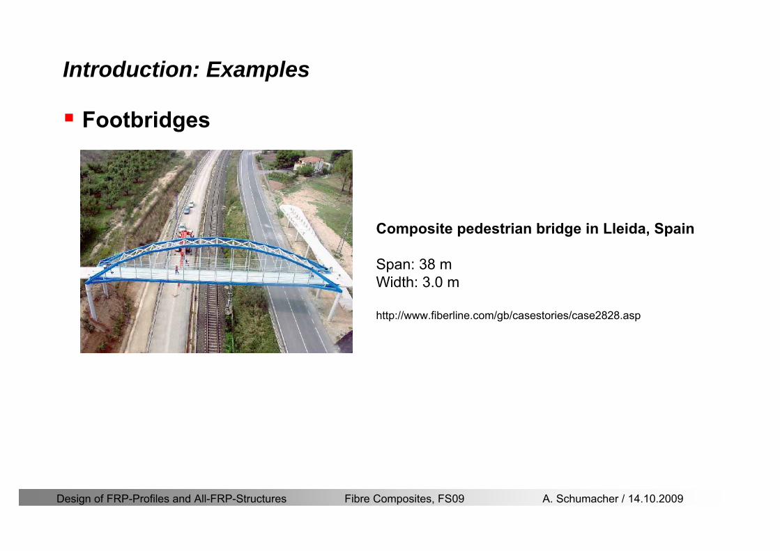
Design of FRP-Profiles and All-FRP-Structures Fibre Composites FS09 A Schumacher 14102009
Introduction Examples
Footbridges
Composite pedestrian bridge in Lleida Spain
Span 38 mWidth 30 m
httpwwwfiberlinecomgbcasestoriescase2828asp
Design of FRP-Profiles and All-FRP-Structures Fibre Composites FS09 A Schumacher 14102009
Introduction Examples (ASSET Profile)
Road bridges
West Mill Bridge England
Span 10 mWidth 68 mLoad capacity 46 tons
httpwwwfiberlinecomgbcasestoriescase3903asp
Klipphausen Bridge Germany
Span 68 mWidth 60 mLoad capacity 40 tons
httpwwwfiberlinecomgbcasestoriescase6314asp
Design of FRP-Profiles and All-FRP-Structures Fibre Composites FS09 A Schumacher 14102009
Introduction Examples
Bridgedeck (Footbridges)Wuumlrenlos Switzerland Loopersteg Switzerland
Design of FRP-Profiles and All-FRP-Structures Fibre Composites FS09 A Schumacher 14102009
Introduction Examples
Buildings
Eyecatcher Building Basel Switzerland
Height 15 mStoreys 5
httpwwwfiberlinecomgbcasestoriescase1835asp
Project Maagtechnic
Design of FRP-Profiles and All-FRP-Structures Fibre Composites FS09 A Schumacher 14102009
Introduction Examples
Laboratory bridgeEmpa Laboratory Bridge Switzerland
Span 19 mWidth 16 mLoad capacity 15 tons
Design of FRP-Profiles and All-FRP-Structures Fibre Composites FS09 A Schumacher 14102009
Introduction Examples
Noise barrier SBB
Goumlschenen Switzerland
Project Maagtechnic
Design of FRP-Profiles and All-FRP-Structures Fibre Composites FS09 A Schumacher 14102009
Introduction Examples
Balconies
Switzerland
Project Maagtechnic
Design of FRP-Profiles and All-FRP-Structures Fibre Composites FS09 A Schumacher 14102009
Introduction Examples
RailingsOensingen Switzerland
Heineken brewery Switzerland
Design of FRP-Profiles and All-FRP-Structures Fibre Composites FS09 A Schumacher 14102009
Introduction Application
Applications where GFRP structures are competitive
Significant corrosion and chemical resistance is required(Food and chemical processing plants cooling towers offshore platforms hellip)
Electromagnetic transparency or electrical insulation is required
Light-weight is cost essential(fast deployment hellip)
Prestige and demonstration objects (eg Novartis Campus Entrance Building)
Photo Prof Th Keller EPFL
Design of FRP-Profiles and All-FRP-Structures Fibre Composites FS09 A Schumacher 14102009
Material
Design of FRP-Profiles and All-FRP-Structures Fibre Composites FS09 A Schumacher 14102009
Only pultruded GFRP profiles will be considered in this lecture
Production of profiles with constant cross-section along the length
High quality
Continuous longitudinal fiber bundles and filament mats
Pultrusion line
Material Pultrusion process
Design of FRP-Profiles and All-FRP-Structures Fibre Composites FS09 A Schumacher 14102009
Material Components
Pultruded profiles contain three primary componentsreinforcement
Matrix
Supplementaryconstituents
polyesterepoxyphenol
polymerisation agentsfillersadditives
Design of FRP-Profiles and All-FRP-Structures Fibre Composites FS09 A Schumacher 14102009
Material Shapes of pultruded profiles
Available Profiles on Stock
Length up to 12 m
Special cross-sections can be designed and ordered(several kilometres are necessary rarr special tools have to be designed)
Design of FRP-Profiles and All-FRP-Structures Fibre Composites FS09 A Schumacher 14102009
Material Durability
Various environmental and load conditions that affect durability of (G)FRPs in terms of strength stiffness fibermatrix interface integrity cracking
watersea waterchemical solutionsprolonged freezingthermal cycling (freeze-thaw)elevated temperature exposureUV radiationcreep and relaxationfatiguefirehellip
Design of FRP-Profiles and All-FRP-Structures Fibre Composites FS09 A Schumacher 14102009
Material Durability
Environmental reduction factor for different FRP systems and exposure conditions
070Aramidepoxy
050Glassepoxy(chemical plants)
085CarbonepoxyAgressive environ
075Aramidepoxyparking garages)
065Glassepoxy(bridges piers
085CarbonepoxyExterior exposure
085Aramidepoxy
075Glassepoxy
095CarbonepoxyInterior exposure
Environ reductionFiber resin typeExposure condition
Design of FRP-Profiles and All-FRP-Structures Fibre Composites FS09 A Schumacher 14102009
Material Durability
GFRP is more susceptible to degradation than CFRP by the following effects
alkaline effects (caution when GFRP in contact with concrete)acid effectssalt effectsfatigueUV radiation
Fire protection is a major (unsolved) issue for (G)FRP structural elements and components
Smoke generation and toxicity must be consideredStrength of GFRP is affected by fatigue loading(more than CFRP)
Design of FRP-Profiles and All-FRP-Structures Fibre Composites FS09 A Schumacher 14102009
Material Manufacturers
GFRP profiles available on stock
In Europe two companies pultrude FRP-Profiles
Fiberline Composites Denmarkwwwfiberlinecom
Fiberline Design Manual (wwwfiberlinedk)rarr helpful tool to design structures
(material properties geometries connections hellip)
Top Glass Italywwwtopglassit
Design of FRP-Profiles and All-FRP-Structures Fibre Composites FS09 A Schumacher 14102009
Material Manufacturers
GFRP profiles available on stock
In North America
Strongwell USAwwwstrongwellcom
Creative Pultrusions USAwwwcreativepultrusionscom
Bedford Reinforced Plastics USAwwwbedfordplasticscom
Design of FRP-Profiles and All-FRP-Structures Fibre Composites FS09 A Schumacher 14102009
Design Concept
Design of FRP-Profiles and All-FRP-Structures Fibre Composites FS09 A Schumacher 14102009
Design Concept Basic Assumptions
Definitions and directions
Design of FRP-Profiles and All-FRP-Structures Fibre Composites FS09 A Schumacher 14102009
Design Concept
Codes
Every manufacturer has its own profile design rarr No European Design Code is available (only EN13706 about testing and notation)
There exists European guidelines EUROCOMP 1996 Design CodeEUROCOMP 1996 Handbook
Fiberline Design Manual is based on Eurocomp 1996
Design concept (according to Eurocodes and Swisscodes)
Partial safety factors
Measured material parameters
Rules for bolted connections
Design of FRP-Profiles and All-FRP-Structures Fibre Composites FS09 A Schumacher 14102009
Design Concept
Concept of Limit State Design (According to Euro Codes and Swiss Codes)
Ultimate limit stress
Ed le Rd
Ed hellip Calculated stress (including load factors) hellip SIA260 261
Rd hellip Rated value of the resistance capability
where
Rk hellip the calculated resistance capability
kd mγ=
RR
Design of FRP-Profiles and All-FRP-Structures Fibre Composites FS09 A Schumacher 14102009
101020Production process
Operating temperature
111116Degree of postcuring
115115225Derivation of mat properties
FiberlineMinMaxDescriptionCoefficient
Design Concept
Reduction coefficient m m1 m2 m3 m4γ γ γ γ γ= sdot sdot sdot
m1γ
m2γ
m3γ
m4γ
mγ mγ
31312580
2510-20 +60
Long-term loadShort-term load
Operatingtemperature degC m4γ
Design of FRP-Profiles and All-FRP-Structures Fibre Composites FS09 A Schumacher 14102009
Design Concept
Serviceability limit states
Ed le Cd
Ed hellip the crucial action effect due to the load cases considered inthe investigated dimensioning situation Typically maximaldeflection response of the structure
Cd hellip corresponding serviceability limit SIA 261
Design of FRP-Profiles and All-FRP-Structures Fibre Composites FS09 A Schumacher 14102009
Design Concept Basic Assumptions
Material Properties stength values (Fiberline Profiles)
Design of FRP-Profiles and All-FRP-Structures Fibre Composites FS09 A Schumacher 14102009
Design Concept Basic Assumptions
Material Properties stiffness values (Fiberline Profiles)
Design of FRP-Profiles and All-FRP-Structures Fibre Composites FS09 A Schumacher 14102009
Design Concept Basic Assumptions
Typical data sheet of a profile (Fiberline I-Profile)
Design of FRP-Profiles and All-FRP-Structures Fibre Composites FS09 A Schumacher 14102009
Bending Beam
Design of FRP-Profiles and All-FRP-Structures Fibre Composites FS09 A Schumacher 14102009
Bending Beam Design of hellip
Calculate bending moments Md and shear forces Qd acting on the profile using the partial coefficient (SIA 260 261)
Ultimate limit state
Bending
Shear
Ak hellip relevant shear area
d max d max 0max
M MW Wy z b
mzy
fσ γ
⎛ ⎞⎜ ⎟⎜ ⎟⎜ ⎟⎜ ⎟⎝ ⎠
deg= + le
d maxmax
kyAy
m
Q fττ γ= le
Design of FRP-Profiles and All-FRP-Structures Fibre Composites FS09 A Schumacher 14102009
Bending Beam Design of hellip
Serviceability limit state
Deflection limit
hellip typically selected between 200 and 400given by SIA 261 or the building owner
hellip calculated including shear deformations
Vibrations
Light-weighted and lsquosoftrsquo structures are susceptible to vibrations (traffic wind the movement of people hellip)
max 1wL αlt
α
maxw
Design of FRP-Profiles and All-FRP-Structures Fibre Composites FS09 A Schumacher 14102009
Bending Beam Timoshenko Theory
Pultruded profiles have a low shear modulus rarr shear deformation must be taken into account
Several bending theories have been published for beams
Euler-Bernoulli theory (1702)
Timoshenko theory (1968)
Higher order beam theory
A simply supported beam with a symmetric cross-section is discussed
Design of FRP-Profiles and All-FRP-Structures Fibre Composites FS09 A Schumacher 14102009
Bending Beam Timoshenko Theory
Cross-sections planeand perpendicular
1 degree of freedom
w
Cross-sections plane butNOT perpendicular
2 degrees of freedom
w and ψ
Cross-sections do NOTremain plane
3+ degrees of freedom
w ψ and hellip
Design of FRP-Profiles and All-FRP-Structures Fibre Composites FS09 A Schumacher 14102009
Bending Beam Euler vs Timoshenko Theory
Kinematic relationships
( )( )
( )
2 0
x x
y
xx xx
yxxy
u y w xu w x
u y w xxuu
y x
ε
ε
=minus sdot=
part= =minus sdotpartpartpart= + =
part part
( )( )
( )
2 ( ) ( )
x
y
xx x
yxxy x
u y xu w x
u y xxuu x w xy x
ψ
ε ψ
ε ψ
=minus sdot=
part= =minus sdotpartpartpart= + =minus +
part part
Hookrsquos law
0degE and G 2x x xy xyσ ε τ ε= sdot = sdot
z0deg E Iz x xxQS
M y dydz wσ= minus sdot sdot = sdot sdotintint
( )
z0deg E I
z x xQS
y xQS
M y dydz
Q dydz w GA
σ ψ
κ τ ψ κ
= minus sdot sdot = sdot
= sdot = minus sdot sdot
intint
intint
Design of FRP-Profiles and All-FRP-Structures Fibre Composites FS09 A Schumacher 14102009
Bending Beam Euler vs Timoshenko Theory
Equilibrium
Solution for the simply supported beam (distributed load)
In a first approximation the deflections are calculated by direct integration of
z0deg
( ) E IxxM xw = sdot
( )( )z0deg
( ) E I 0x
x
xx x
xx x
q x w GAw GA
QM Q
ψ κψ ψ κ
minus minus sdot sdot
sdot + minus sdot sdot
=minus =
= =minus
Equilibrium on an infinitesimal beam element
Coupled second order differential equation
21 1( ) (0) 0 and ( ) 02 2
M x qLx qx w w L= minus = =
( )3 2 3
0deg z
( ) 224 E Iqxw x L Lx x= sdot minus +sdot sdot
2
0deg z
1 1 1E I 2 2xxw qLx qx⎛ ⎞= minus⎜ ⎟sdot ⎝ ⎠
(0) 0 and ( ) 0(0) 0 (0) 0 and ( ) 0 ( ) 0 x x
w w LM M L Lψ ψ
= == rarr = = rarr =
Functions4 3 2
1 2 3 4 53 2
1 2 3 4
( )
( )
w x A x A x A x A x A
x B x B x B x Bψ
= + + + +
= + + +
Design of FRP-Profiles and All-FRP-Structures Fibre Composites FS09 A Schumacher 14102009
Put in and solve for the coefficients rarr
Bending Beam Euler vs Timoshenko Theory
Use the boundary conditions and the second differential eq to calculate A1 ndash A5
( )0deg z E I 0xx xw GAψ ψ κsdot + minus sdot sdot =
1 01 1 3 3
2 02 2 4 4
24 E I4 2GA
6 E I3 GA
z
z
AB A B A
AB A B A
κ
κ
deg
deg
sdot= minus = minus minus
sdotsdot
= minus = minus minussdot
( ) ( )( )2 2
0
( )2 GA 24 E Iz
qx L x L Lx xqx L xw x
κ deg
minus + minusminus= +
sdot sdot sdot
Deflection at midspan
4
0
52 384 E Iz
qLLw⎛ ⎞⎜ ⎟⎝ ⎠
deg
sdot= sdot4 2
0
52 384 E I 8 GAz
qL q LLw κ⎛ ⎞ +⎜ ⎟⎝ ⎠
deg
sdot sdot= sdot sdot sdot
Design of FRP-Profiles and All-FRP-Structures Fibre Composites FS09 A Schumacher 14102009
General expression for the total beam deflection as a sum of the deflection due to bending and shear
GAxf
IExfxwz sdot+=
deg κ)()()( 2
0
1
Cantilever beam
Simply supported
Concentrated load (P)
Uniformly distr load (q)
Concentrated load (P)
Uniformly distr load (q)
Beam )( max1 wf
3845 4qLsdot
48
3PL
8
4qL
3
3PL
)( max1 wf
8
2qL
4PL
2
2qL
PL
)( maxwx
2L
2L
L
L
Bending Beam Euler vs Timoshenko Theory
Design of FRP-Profiles and All-FRP-Structures Fibre Composites FS09 A Schumacher 14102009
Bending Beam Euler vs Timoshenko Theory
Example influence of the shear deformation
Profile 300 x 150 mm I-beam
Load uniformly distributed
General rule of thumbfor GFRP beams withspandepth gt 25 sheardeformation can beignored
Design of FRP-Profiles and All-FRP-Structures Fibre Composites FS09 A Schumacher 14102009
Bending Beam Example
Choose an appropriate Profile for the following specifications
1 Deflections and loading
=
=
==
1300 rarr wmax=001 mwmaxL
10 kNmqdser
13 kNmqduls
30 mL
max
4 2
0
5384 E I 8 GA
d ser d serz
q L q Lw κ+
deg
sdot sdot= sdot sdot sdot
2
maxz8 2 I
d ulsq L hσ sdot= sdot
maxky
12 Ad ulsq L
τ sdot=
Design of FRP-Profiles and All-FRP-Structures Fibre Composites FS09 A Schumacher 14102009
Bending Beam Example
2 Find a profile with sufficient bending stiffness
Shear deformations are neglected in a first step
rarr from specification table choose I 240x120x12 rarr
3 Check the bending and shear stresses
6 24
0 max
1054 10 Nm5
E I 384d ser
zq Lwdeg = sdot
sdotsdotge
6 20 1369 10 NmE Izdeg = sdot
2
maxz
358 MPa8 2 Id ulsq L hσ sdot= =sdot
max
ky
1 71 MPa2 Ad ulsq L
τ sdot= =
0 185 MPab df degle =
20 MPadfτle =
Design of FRP-Profiles and All-FRP-Structures Fibre Composites FS09 A Schumacher 14102009
Bending Beam Example
m10398384
5 32
0
4
maxminus
deg
sdot=sdotsdotsdot
+sdot
sdot=
GALq
IELq
w serd
z
serd
κ
4 Check deflection (including shear deformation)
5 Remarks
The design of GFRP-profiles is mostly driven by serviceability criteria
Start the design iteration procedure using the maximal deflection criterion
max 001 mwle =
m10198384
5 32
0
4
maxminus
deg
sdot=sdot
sdot+
sdotsdot
=web
serd
z
serd
GALq
IELq
w
(77 mm) (16 mm)
Design of FRP-Profiles and All-FRP-Structures Fibre Composites FS09 A Schumacher 14102009
Bending Beam Stability problems
Lateral-torsional bucklingFlange (compressive) displace laterally to the transverse load direction
Torsional stiffness is too low (especially for open section profiles)
Theoretical calculations or design measuresrarr see eg LP Kollaacuter 2003
Mechanics of composite structuresExample
Compressive flanges are kept in place by connection to the bridge deck
Design of FRP-Profiles and All-FRP-Structures Fibre Composites FS09 A Schumacher 14102009
Bending Beam Stability problems
Flange (compressive) displaces in the direction of the transverse load
Low bending stiffness perpendicular to the pultrusion direction
Weak fiber mats
Local buckling of walls due to in-plane compression
Local buckling of walls due to in-plane shear
Web crushing and web buckling in transverse direction
Design of FRP-Profiles and All-FRP-Structures Fibre Composites FS09 A Schumacher 14102009
Axial Members
Design of FRP-Profiles and All-FRP-Structures Fibre Composites FS09 A Schumacher 14102009
Axial Members Tension
Ultimate limit state under axial tension Nd
Serviceability limit state
Remark The critical aspect of axial members in tension are neither the serviceability nor the ultimate limit state Critical is the load transfer to the GFRP profile
0NdA
tm
fγ
degle
0deg
N LE Axδ sdot= sdot
Design of FRP-Profiles and All-FRP-Structures Fibre Composites FS09 A Schumacher 14102009
Axial Members Compression
Ultimate limit state under axial compression Nd
hellip maximal compressive load
hellip Euler load
hellip Buckling length for columns
hellip coefficient for Youngrsquos modulus = 13
cc
Euler
FNd F1 N
le+
c0degC
A fF
mγsdot
=
20
Euler 2
Nm E k
E IL
πγ
degsdot sdot=
sdot
kL
m Eγ
Design of FRP-Profiles and All-FRP-Structures Fibre Composites FS09 A Schumacher 14102009
Axial Members Compression
The influence of shear deformation should be considered but in the most cases the influence will be small (less than 5)
Local buckling should be considered for short columns
For more information on the various buckling modes and effects rarr see LP Kollaacuter 2003 Mechanics of composite structures
Global buckling Local buckling
Design of FRP-Profiles and All-FRP-Structures Fibre Composites FS09 A Schumacher 14102009
Connections
Design of FRP-Profiles and All-FRP-Structures Fibre Composites FS09 A Schumacher 14102009
Connections Introduction
Design of FRP-Profiles and All-FRP-Structures Fibre Composites FS09 A Schumacher 14102009
Connections Introduction
(from Eurocomp Design Code 1996)
Design of FRP-Profiles and All-FRP-Structures Fibre Composites FS09 A Schumacher 14102009
Connections Bolted joints
Bolts = Stress concentration in the profile and the bolt
It is necessary to ensure that the bolts and the profilecan withstand this concentrated local stress compression
It is necessary to ensure that the region surroundinga group of bolts will not be torn out of the profile
Basic failure modesin bolted shearconnections
bolt shear failure
Design of FRP-Profiles and All-FRP-Structures Fibre Composites FS09 A Schumacher 14102009
Connections Bolted joints
The design procedure is comparable to the one for steel connections but since there exist no standard GFRP material rarr each manufacturer has its own design rules for bolted joints
IMPORTANT REMARKS
The direction of pultrusion and the direction of the force is RELEVANT(anisotropic material)
Use stainless or galvanised steel
Do not cut threads in the composite material
Use screws with shafts
Design of FRP-Profiles and All-FRP-Structures Fibre Composites FS09 A Schumacher 14102009
Calculation of load bearing capacity of bolts
Shear in longitudinal direction (0deg)
Shear in transverse direction (90deg)
Tensile force
Minimum distances
Connections Bolted joints (Fiberline recommendations)
Design of FRP-Profiles and All-FRP-Structures Fibre Composites FS09 A Schumacher 14102009
Joint capacity tables available for shear and tension
m
150 MPa( 13)B d
d tP γsdot sdot=
=
Shear in longitudinal direction 0deg
m
70 MPa( 13)B d
d tP γsdot sdot=
=
Shear in transverse direction 90deg
Connections Bolted joints (Fiberline recommendations)
Design of FRP-Profiles and All-FRP-Structures Fibre Composites FS09 A Schumacher 14102009
Bolted connection in shear eg shear in longitudinal direction
Connections Bolted joints (Fiberline recommendations)
γmPBolt le dt720 MPaγmPBolt le dt240 MPa
γmPBolt le dt240 MPa γmPBolt le dt240 MPaγmPBolt le dt150 MPa
Design of FRP-Profiles and All-FRP-Structures Fibre Composites FS09 A Schumacher 14102009
Bolted connections in tension
Static conditions
Bolt Tearing of bolt in threaded cross-section
Laminate Shear fracture at rim of washer
Geometry and strength
Diameter of washer2d
Tensile strength of bolt hellipfyk
Shear strength of laminatehellipfτ
Thickness of laminatet
Stress area of the boltAs
Diameter of the boltd
s ykd m
A fP γ
sdotle
2d m
d t fP τπγ
sdot sdot sdot sdotle
Connections Bolted joints (Fiberline recommendations)
Design of FRP-Profiles and All-FRP-Structures Fibre Composites FS09 A Schumacher 14102009
Connections Bonded joints
Using an adhesive agent for joining profiles can have advantages
Easy to use easy to make aesthetic joints
Typically more rigid than bolted joints
Glued joints subjected to dynamic loads are good
But be careful hellipAdhesive agents have properties that depend on time temperature humidity hellip
Failure in glued joints takes place suddenly (brittle behaviour)
The load-bearing capacity is not proportional to the area which is glued
The design of bonded joints may be based onAnalytical models for plate-to-plate connections (see Eurocomp 1996 Design Code)
Design guidelines supplemented by testing
Finite element analysis
Design of FRP-Profiles and All-FRP-Structures Fibre Composites FS09 A Schumacher 14102009
Connections Bonded joints
A bonded joint has the following three primary failure modes
adhesive failure
cohesive failure of adhesive
cohesive failure of adherend
The design of any bonded joint shall satisfy the following conditions
allowable shear stress in the adhesive is not exceeded
allowable tensile (peel) stress in the adhesive is not exceeded
allowable through-thickness tensile stress of the adhesive is not exceeded
allowable in-plane shear stress of the adherend should not be exceeded
The calculation of the stresses has to be done very carefully Often calculations are supplemented by testing
Design of FRP-Profiles and All-FRP-Structures Fibre Composites FS09 A Schumacher 14102009
Connections Bonded joints
Different types of bonded joint configurations
Research on bonded joints for structuralapplications
Design of FRP-Profiles and All-FRP-Structures Fibre Composites FS09 A Schumacher 14102009
Connections Other joints
Brackets for assembly (Fiberline)
Custom pultruded connections
Design of FRP-Profiles and All-FRP-Structures Fibre Composites FS09 A Schumacher 14102009
GFRP Some final remarks
Perpendicular to the direction of pultrusion the material is WEAK and SOFTrarr avoid such loadings if possible
In order to use pultruded GFRP-profiles economically the design must be done in a clever way eg for bridges the railings should be used as part of the load-bearing structure
GFRP structures are very light rarr vibration problems may occur

Design of FRP-Profiles and All-FRP-Structures Fibre Composites FS09 A Schumacher 14102009
Introduction Examples (ASSET Profile)
Road bridges
West Mill Bridge England
Span 10 mWidth 68 mLoad capacity 46 tons
httpwwwfiberlinecomgbcasestoriescase3903asp
Klipphausen Bridge Germany
Span 68 mWidth 60 mLoad capacity 40 tons
httpwwwfiberlinecomgbcasestoriescase6314asp
Design of FRP-Profiles and All-FRP-Structures Fibre Composites FS09 A Schumacher 14102009
Introduction Examples
Bridgedeck (Footbridges)Wuumlrenlos Switzerland Loopersteg Switzerland
Design of FRP-Profiles and All-FRP-Structures Fibre Composites FS09 A Schumacher 14102009
Introduction Examples
Buildings
Eyecatcher Building Basel Switzerland
Height 15 mStoreys 5
httpwwwfiberlinecomgbcasestoriescase1835asp
Project Maagtechnic
Design of FRP-Profiles and All-FRP-Structures Fibre Composites FS09 A Schumacher 14102009
Introduction Examples
Laboratory bridgeEmpa Laboratory Bridge Switzerland
Span 19 mWidth 16 mLoad capacity 15 tons
Design of FRP-Profiles and All-FRP-Structures Fibre Composites FS09 A Schumacher 14102009
Introduction Examples
Noise barrier SBB
Goumlschenen Switzerland
Project Maagtechnic
Design of FRP-Profiles and All-FRP-Structures Fibre Composites FS09 A Schumacher 14102009
Introduction Examples
Balconies
Switzerland
Project Maagtechnic
Design of FRP-Profiles and All-FRP-Structures Fibre Composites FS09 A Schumacher 14102009
Introduction Examples
RailingsOensingen Switzerland
Heineken brewery Switzerland
Design of FRP-Profiles and All-FRP-Structures Fibre Composites FS09 A Schumacher 14102009
Introduction Application
Applications where GFRP structures are competitive
Significant corrosion and chemical resistance is required(Food and chemical processing plants cooling towers offshore platforms hellip)
Electromagnetic transparency or electrical insulation is required
Light-weight is cost essential(fast deployment hellip)
Prestige and demonstration objects (eg Novartis Campus Entrance Building)
Photo Prof Th Keller EPFL
Design of FRP-Profiles and All-FRP-Structures Fibre Composites FS09 A Schumacher 14102009
Material
Design of FRP-Profiles and All-FRP-Structures Fibre Composites FS09 A Schumacher 14102009
Only pultruded GFRP profiles will be considered in this lecture
Production of profiles with constant cross-section along the length
High quality
Continuous longitudinal fiber bundles and filament mats
Pultrusion line
Material Pultrusion process
Design of FRP-Profiles and All-FRP-Structures Fibre Composites FS09 A Schumacher 14102009
Material Components
Pultruded profiles contain three primary componentsreinforcement
Matrix
Supplementaryconstituents
polyesterepoxyphenol
polymerisation agentsfillersadditives
Design of FRP-Profiles and All-FRP-Structures Fibre Composites FS09 A Schumacher 14102009
Material Shapes of pultruded profiles
Available Profiles on Stock
Length up to 12 m
Special cross-sections can be designed and ordered(several kilometres are necessary rarr special tools have to be designed)
Design of FRP-Profiles and All-FRP-Structures Fibre Composites FS09 A Schumacher 14102009
Material Durability
Various environmental and load conditions that affect durability of (G)FRPs in terms of strength stiffness fibermatrix interface integrity cracking
watersea waterchemical solutionsprolonged freezingthermal cycling (freeze-thaw)elevated temperature exposureUV radiationcreep and relaxationfatiguefirehellip
Design of FRP-Profiles and All-FRP-Structures Fibre Composites FS09 A Schumacher 14102009
Material Durability
Environmental reduction factor for different FRP systems and exposure conditions
070Aramidepoxy
050Glassepoxy(chemical plants)
085CarbonepoxyAgressive environ
075Aramidepoxyparking garages)
065Glassepoxy(bridges piers
085CarbonepoxyExterior exposure
085Aramidepoxy
075Glassepoxy
095CarbonepoxyInterior exposure
Environ reductionFiber resin typeExposure condition
Design of FRP-Profiles and All-FRP-Structures Fibre Composites FS09 A Schumacher 14102009
Material Durability
GFRP is more susceptible to degradation than CFRP by the following effects
alkaline effects (caution when GFRP in contact with concrete)acid effectssalt effectsfatigueUV radiation
Fire protection is a major (unsolved) issue for (G)FRP structural elements and components
Smoke generation and toxicity must be consideredStrength of GFRP is affected by fatigue loading(more than CFRP)
Design of FRP-Profiles and All-FRP-Structures Fibre Composites FS09 A Schumacher 14102009
Material Manufacturers
GFRP profiles available on stock
In Europe two companies pultrude FRP-Profiles
Fiberline Composites Denmarkwwwfiberlinecom
Fiberline Design Manual (wwwfiberlinedk)rarr helpful tool to design structures
(material properties geometries connections hellip)
Top Glass Italywwwtopglassit
Design of FRP-Profiles and All-FRP-Structures Fibre Composites FS09 A Schumacher 14102009
Material Manufacturers
GFRP profiles available on stock
In North America
Strongwell USAwwwstrongwellcom
Creative Pultrusions USAwwwcreativepultrusionscom
Bedford Reinforced Plastics USAwwwbedfordplasticscom
Design of FRP-Profiles and All-FRP-Structures Fibre Composites FS09 A Schumacher 14102009
Design Concept
Design of FRP-Profiles and All-FRP-Structures Fibre Composites FS09 A Schumacher 14102009
Design Concept Basic Assumptions
Definitions and directions
Design of FRP-Profiles and All-FRP-Structures Fibre Composites FS09 A Schumacher 14102009
Design Concept
Codes
Every manufacturer has its own profile design rarr No European Design Code is available (only EN13706 about testing and notation)
There exists European guidelines EUROCOMP 1996 Design CodeEUROCOMP 1996 Handbook
Fiberline Design Manual is based on Eurocomp 1996
Design concept (according to Eurocodes and Swisscodes)
Partial safety factors
Measured material parameters
Rules for bolted connections
Design of FRP-Profiles and All-FRP-Structures Fibre Composites FS09 A Schumacher 14102009
Design Concept
Concept of Limit State Design (According to Euro Codes and Swiss Codes)
Ultimate limit stress
Ed le Rd
Ed hellip Calculated stress (including load factors) hellip SIA260 261
Rd hellip Rated value of the resistance capability
where
Rk hellip the calculated resistance capability
kd mγ=
RR
Design of FRP-Profiles and All-FRP-Structures Fibre Composites FS09 A Schumacher 14102009
101020Production process
Operating temperature
111116Degree of postcuring
115115225Derivation of mat properties
FiberlineMinMaxDescriptionCoefficient
Design Concept
Reduction coefficient m m1 m2 m3 m4γ γ γ γ γ= sdot sdot sdot
m1γ
m2γ
m3γ
m4γ
mγ mγ
31312580
2510-20 +60
Long-term loadShort-term load
Operatingtemperature degC m4γ
Design of FRP-Profiles and All-FRP-Structures Fibre Composites FS09 A Schumacher 14102009
Design Concept
Serviceability limit states
Ed le Cd
Ed hellip the crucial action effect due to the load cases considered inthe investigated dimensioning situation Typically maximaldeflection response of the structure
Cd hellip corresponding serviceability limit SIA 261
Design of FRP-Profiles and All-FRP-Structures Fibre Composites FS09 A Schumacher 14102009
Design Concept Basic Assumptions
Material Properties stength values (Fiberline Profiles)
Design of FRP-Profiles and All-FRP-Structures Fibre Composites FS09 A Schumacher 14102009
Design Concept Basic Assumptions
Material Properties stiffness values (Fiberline Profiles)
Design of FRP-Profiles and All-FRP-Structures Fibre Composites FS09 A Schumacher 14102009
Design Concept Basic Assumptions
Typical data sheet of a profile (Fiberline I-Profile)
Design of FRP-Profiles and All-FRP-Structures Fibre Composites FS09 A Schumacher 14102009
Bending Beam
Design of FRP-Profiles and All-FRP-Structures Fibre Composites FS09 A Schumacher 14102009
Bending Beam Design of hellip
Calculate bending moments Md and shear forces Qd acting on the profile using the partial coefficient (SIA 260 261)
Ultimate limit state
Bending
Shear
Ak hellip relevant shear area
d max d max 0max
M MW Wy z b
mzy
fσ γ
⎛ ⎞⎜ ⎟⎜ ⎟⎜ ⎟⎜ ⎟⎝ ⎠
deg= + le
d maxmax
kyAy
m
Q fττ γ= le
Design of FRP-Profiles and All-FRP-Structures Fibre Composites FS09 A Schumacher 14102009
Bending Beam Design of hellip
Serviceability limit state
Deflection limit
hellip typically selected between 200 and 400given by SIA 261 or the building owner
hellip calculated including shear deformations
Vibrations
Light-weighted and lsquosoftrsquo structures are susceptible to vibrations (traffic wind the movement of people hellip)
max 1wL αlt
α
maxw
Design of FRP-Profiles and All-FRP-Structures Fibre Composites FS09 A Schumacher 14102009
Bending Beam Timoshenko Theory
Pultruded profiles have a low shear modulus rarr shear deformation must be taken into account
Several bending theories have been published for beams
Euler-Bernoulli theory (1702)
Timoshenko theory (1968)
Higher order beam theory
A simply supported beam with a symmetric cross-section is discussed
Design of FRP-Profiles and All-FRP-Structures Fibre Composites FS09 A Schumacher 14102009
Bending Beam Timoshenko Theory
Cross-sections planeand perpendicular
1 degree of freedom
w
Cross-sections plane butNOT perpendicular
2 degrees of freedom
w and ψ
Cross-sections do NOTremain plane
3+ degrees of freedom
w ψ and hellip
Design of FRP-Profiles and All-FRP-Structures Fibre Composites FS09 A Schumacher 14102009
Bending Beam Euler vs Timoshenko Theory
Kinematic relationships
( )( )
( )
2 0
x x
y
xx xx
yxxy
u y w xu w x
u y w xxuu
y x
ε
ε
=minus sdot=
part= =minus sdotpartpartpart= + =
part part
( )( )
( )
2 ( ) ( )
x
y
xx x
yxxy x
u y xu w x
u y xxuu x w xy x
ψ
ε ψ
ε ψ
=minus sdot=
part= =minus sdotpartpartpart= + =minus +
part part
Hookrsquos law
0degE and G 2x x xy xyσ ε τ ε= sdot = sdot
z0deg E Iz x xxQS
M y dydz wσ= minus sdot sdot = sdot sdotintint
( )
z0deg E I
z x xQS
y xQS
M y dydz
Q dydz w GA
σ ψ
κ τ ψ κ
= minus sdot sdot = sdot
= sdot = minus sdot sdot
intint
intint
Design of FRP-Profiles and All-FRP-Structures Fibre Composites FS09 A Schumacher 14102009
Bending Beam Euler vs Timoshenko Theory
Equilibrium
Solution for the simply supported beam (distributed load)
In a first approximation the deflections are calculated by direct integration of
z0deg
( ) E IxxM xw = sdot
( )( )z0deg
( ) E I 0x
x
xx x
xx x
q x w GAw GA
QM Q
ψ κψ ψ κ
minus minus sdot sdot
sdot + minus sdot sdot
=minus =
= =minus
Equilibrium on an infinitesimal beam element
Coupled second order differential equation
21 1( ) (0) 0 and ( ) 02 2
M x qLx qx w w L= minus = =
( )3 2 3
0deg z
( ) 224 E Iqxw x L Lx x= sdot minus +sdot sdot
2
0deg z
1 1 1E I 2 2xxw qLx qx⎛ ⎞= minus⎜ ⎟sdot ⎝ ⎠
(0) 0 and ( ) 0(0) 0 (0) 0 and ( ) 0 ( ) 0 x x
w w LM M L Lψ ψ
= == rarr = = rarr =
Functions4 3 2
1 2 3 4 53 2
1 2 3 4
( )
( )
w x A x A x A x A x A
x B x B x B x Bψ
= + + + +
= + + +
Design of FRP-Profiles and All-FRP-Structures Fibre Composites FS09 A Schumacher 14102009
Put in and solve for the coefficients rarr
Bending Beam Euler vs Timoshenko Theory
Use the boundary conditions and the second differential eq to calculate A1 ndash A5
( )0deg z E I 0xx xw GAψ ψ κsdot + minus sdot sdot =
1 01 1 3 3
2 02 2 4 4
24 E I4 2GA
6 E I3 GA
z
z
AB A B A
AB A B A
κ
κ
deg
deg
sdot= minus = minus minus
sdotsdot
= minus = minus minussdot
( ) ( )( )2 2
0
( )2 GA 24 E Iz
qx L x L Lx xqx L xw x
κ deg
minus + minusminus= +
sdot sdot sdot
Deflection at midspan
4
0
52 384 E Iz
qLLw⎛ ⎞⎜ ⎟⎝ ⎠
deg
sdot= sdot4 2
0
52 384 E I 8 GAz
qL q LLw κ⎛ ⎞ +⎜ ⎟⎝ ⎠
deg
sdot sdot= sdot sdot sdot
Design of FRP-Profiles and All-FRP-Structures Fibre Composites FS09 A Schumacher 14102009
General expression for the total beam deflection as a sum of the deflection due to bending and shear
GAxf
IExfxwz sdot+=
deg κ)()()( 2
0
1
Cantilever beam
Simply supported
Concentrated load (P)
Uniformly distr load (q)
Concentrated load (P)
Uniformly distr load (q)
Beam )( max1 wf
3845 4qLsdot
48
3PL
8
4qL
3
3PL
)( max1 wf
8
2qL
4PL
2
2qL
PL
)( maxwx
2L
2L
L
L
Bending Beam Euler vs Timoshenko Theory
Design of FRP-Profiles and All-FRP-Structures Fibre Composites FS09 A Schumacher 14102009
Bending Beam Euler vs Timoshenko Theory
Example influence of the shear deformation
Profile 300 x 150 mm I-beam
Load uniformly distributed
General rule of thumbfor GFRP beams withspandepth gt 25 sheardeformation can beignored
Design of FRP-Profiles and All-FRP-Structures Fibre Composites FS09 A Schumacher 14102009
Bending Beam Example
Choose an appropriate Profile for the following specifications
1 Deflections and loading
=
=
==
1300 rarr wmax=001 mwmaxL
10 kNmqdser
13 kNmqduls
30 mL
max
4 2
0
5384 E I 8 GA
d ser d serz
q L q Lw κ+
deg
sdot sdot= sdot sdot sdot
2
maxz8 2 I
d ulsq L hσ sdot= sdot
maxky
12 Ad ulsq L
τ sdot=
Design of FRP-Profiles and All-FRP-Structures Fibre Composites FS09 A Schumacher 14102009
Bending Beam Example
2 Find a profile with sufficient bending stiffness
Shear deformations are neglected in a first step
rarr from specification table choose I 240x120x12 rarr
3 Check the bending and shear stresses
6 24
0 max
1054 10 Nm5
E I 384d ser
zq Lwdeg = sdot
sdotsdotge
6 20 1369 10 NmE Izdeg = sdot
2
maxz
358 MPa8 2 Id ulsq L hσ sdot= =sdot
max
ky
1 71 MPa2 Ad ulsq L
τ sdot= =
0 185 MPab df degle =
20 MPadfτle =
Design of FRP-Profiles and All-FRP-Structures Fibre Composites FS09 A Schumacher 14102009
Bending Beam Example
m10398384
5 32
0
4
maxminus
deg
sdot=sdotsdotsdot
+sdot
sdot=
GALq
IELq
w serd
z
serd
κ
4 Check deflection (including shear deformation)
5 Remarks
The design of GFRP-profiles is mostly driven by serviceability criteria
Start the design iteration procedure using the maximal deflection criterion
max 001 mwle =
m10198384
5 32
0
4
maxminus
deg
sdot=sdot
sdot+
sdotsdot
=web
serd
z
serd
GALq
IELq
w
(77 mm) (16 mm)
Design of FRP-Profiles and All-FRP-Structures Fibre Composites FS09 A Schumacher 14102009
Bending Beam Stability problems
Lateral-torsional bucklingFlange (compressive) displace laterally to the transverse load direction
Torsional stiffness is too low (especially for open section profiles)
Theoretical calculations or design measuresrarr see eg LP Kollaacuter 2003
Mechanics of composite structuresExample
Compressive flanges are kept in place by connection to the bridge deck
Design of FRP-Profiles and All-FRP-Structures Fibre Composites FS09 A Schumacher 14102009
Bending Beam Stability problems
Flange (compressive) displaces in the direction of the transverse load
Low bending stiffness perpendicular to the pultrusion direction
Weak fiber mats
Local buckling of walls due to in-plane compression
Local buckling of walls due to in-plane shear
Web crushing and web buckling in transverse direction
Design of FRP-Profiles and All-FRP-Structures Fibre Composites FS09 A Schumacher 14102009
Axial Members
Design of FRP-Profiles and All-FRP-Structures Fibre Composites FS09 A Schumacher 14102009
Axial Members Tension
Ultimate limit state under axial tension Nd
Serviceability limit state
Remark The critical aspect of axial members in tension are neither the serviceability nor the ultimate limit state Critical is the load transfer to the GFRP profile
0NdA
tm
fγ
degle
0deg
N LE Axδ sdot= sdot
Design of FRP-Profiles and All-FRP-Structures Fibre Composites FS09 A Schumacher 14102009
Axial Members Compression
Ultimate limit state under axial compression Nd
hellip maximal compressive load
hellip Euler load
hellip Buckling length for columns
hellip coefficient for Youngrsquos modulus = 13
cc
Euler
FNd F1 N
le+
c0degC
A fF
mγsdot
=
20
Euler 2
Nm E k
E IL
πγ
degsdot sdot=
sdot
kL
m Eγ
Design of FRP-Profiles and All-FRP-Structures Fibre Composites FS09 A Schumacher 14102009
Axial Members Compression
The influence of shear deformation should be considered but in the most cases the influence will be small (less than 5)
Local buckling should be considered for short columns
For more information on the various buckling modes and effects rarr see LP Kollaacuter 2003 Mechanics of composite structures
Global buckling Local buckling
Design of FRP-Profiles and All-FRP-Structures Fibre Composites FS09 A Schumacher 14102009
Connections
Design of FRP-Profiles and All-FRP-Structures Fibre Composites FS09 A Schumacher 14102009
Connections Introduction
Design of FRP-Profiles and All-FRP-Structures Fibre Composites FS09 A Schumacher 14102009
Connections Introduction
(from Eurocomp Design Code 1996)
Design of FRP-Profiles and All-FRP-Structures Fibre Composites FS09 A Schumacher 14102009
Connections Bolted joints
Bolts = Stress concentration in the profile and the bolt
It is necessary to ensure that the bolts and the profilecan withstand this concentrated local stress compression
It is necessary to ensure that the region surroundinga group of bolts will not be torn out of the profile
Basic failure modesin bolted shearconnections
bolt shear failure
Design of FRP-Profiles and All-FRP-Structures Fibre Composites FS09 A Schumacher 14102009
Connections Bolted joints
The design procedure is comparable to the one for steel connections but since there exist no standard GFRP material rarr each manufacturer has its own design rules for bolted joints
IMPORTANT REMARKS
The direction of pultrusion and the direction of the force is RELEVANT(anisotropic material)
Use stainless or galvanised steel
Do not cut threads in the composite material
Use screws with shafts
Design of FRP-Profiles and All-FRP-Structures Fibre Composites FS09 A Schumacher 14102009
Calculation of load bearing capacity of bolts
Shear in longitudinal direction (0deg)
Shear in transverse direction (90deg)
Tensile force
Minimum distances
Connections Bolted joints (Fiberline recommendations)
Design of FRP-Profiles and All-FRP-Structures Fibre Composites FS09 A Schumacher 14102009
Joint capacity tables available for shear and tension
m
150 MPa( 13)B d
d tP γsdot sdot=
=
Shear in longitudinal direction 0deg
m
70 MPa( 13)B d
d tP γsdot sdot=
=
Shear in transverse direction 90deg
Connections Bolted joints (Fiberline recommendations)
Design of FRP-Profiles and All-FRP-Structures Fibre Composites FS09 A Schumacher 14102009
Bolted connection in shear eg shear in longitudinal direction
Connections Bolted joints (Fiberline recommendations)
γmPBolt le dt720 MPaγmPBolt le dt240 MPa
γmPBolt le dt240 MPa γmPBolt le dt240 MPaγmPBolt le dt150 MPa
Design of FRP-Profiles and All-FRP-Structures Fibre Composites FS09 A Schumacher 14102009
Bolted connections in tension
Static conditions
Bolt Tearing of bolt in threaded cross-section
Laminate Shear fracture at rim of washer
Geometry and strength
Diameter of washer2d
Tensile strength of bolt hellipfyk
Shear strength of laminatehellipfτ
Thickness of laminatet
Stress area of the boltAs
Diameter of the boltd
s ykd m
A fP γ
sdotle
2d m
d t fP τπγ
sdot sdot sdot sdotle
Connections Bolted joints (Fiberline recommendations)
Design of FRP-Profiles and All-FRP-Structures Fibre Composites FS09 A Schumacher 14102009
Connections Bonded joints
Using an adhesive agent for joining profiles can have advantages
Easy to use easy to make aesthetic joints
Typically more rigid than bolted joints
Glued joints subjected to dynamic loads are good
But be careful hellipAdhesive agents have properties that depend on time temperature humidity hellip
Failure in glued joints takes place suddenly (brittle behaviour)
The load-bearing capacity is not proportional to the area which is glued
The design of bonded joints may be based onAnalytical models for plate-to-plate connections (see Eurocomp 1996 Design Code)
Design guidelines supplemented by testing
Finite element analysis
Design of FRP-Profiles and All-FRP-Structures Fibre Composites FS09 A Schumacher 14102009
Connections Bonded joints
A bonded joint has the following three primary failure modes
adhesive failure
cohesive failure of adhesive
cohesive failure of adherend
The design of any bonded joint shall satisfy the following conditions
allowable shear stress in the adhesive is not exceeded
allowable tensile (peel) stress in the adhesive is not exceeded
allowable through-thickness tensile stress of the adhesive is not exceeded
allowable in-plane shear stress of the adherend should not be exceeded
The calculation of the stresses has to be done very carefully Often calculations are supplemented by testing
Design of FRP-Profiles and All-FRP-Structures Fibre Composites FS09 A Schumacher 14102009
Connections Bonded joints
Different types of bonded joint configurations
Research on bonded joints for structuralapplications
Design of FRP-Profiles and All-FRP-Structures Fibre Composites FS09 A Schumacher 14102009
Connections Other joints
Brackets for assembly (Fiberline)
Custom pultruded connections
Design of FRP-Profiles and All-FRP-Structures Fibre Composites FS09 A Schumacher 14102009
GFRP Some final remarks
Perpendicular to the direction of pultrusion the material is WEAK and SOFTrarr avoid such loadings if possible
In order to use pultruded GFRP-profiles economically the design must be done in a clever way eg for bridges the railings should be used as part of the load-bearing structure
GFRP structures are very light rarr vibration problems may occur
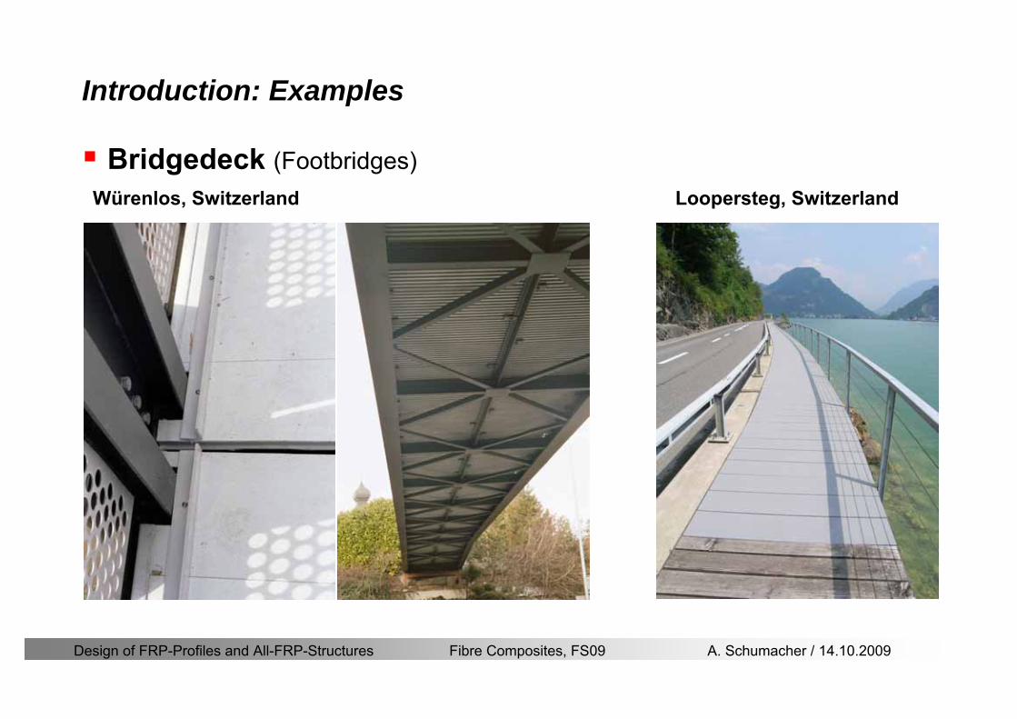
Design of FRP-Profiles and All-FRP-Structures Fibre Composites FS09 A Schumacher 14102009
Introduction Examples
Bridgedeck (Footbridges)Wuumlrenlos Switzerland Loopersteg Switzerland
Design of FRP-Profiles and All-FRP-Structures Fibre Composites FS09 A Schumacher 14102009
Introduction Examples
Buildings
Eyecatcher Building Basel Switzerland
Height 15 mStoreys 5
httpwwwfiberlinecomgbcasestoriescase1835asp
Project Maagtechnic
Design of FRP-Profiles and All-FRP-Structures Fibre Composites FS09 A Schumacher 14102009
Introduction Examples
Laboratory bridgeEmpa Laboratory Bridge Switzerland
Span 19 mWidth 16 mLoad capacity 15 tons
Design of FRP-Profiles and All-FRP-Structures Fibre Composites FS09 A Schumacher 14102009
Introduction Examples
Noise barrier SBB
Goumlschenen Switzerland
Project Maagtechnic
Design of FRP-Profiles and All-FRP-Structures Fibre Composites FS09 A Schumacher 14102009
Introduction Examples
Balconies
Switzerland
Project Maagtechnic
Design of FRP-Profiles and All-FRP-Structures Fibre Composites FS09 A Schumacher 14102009
Introduction Examples
RailingsOensingen Switzerland
Heineken brewery Switzerland
Design of FRP-Profiles and All-FRP-Structures Fibre Composites FS09 A Schumacher 14102009
Introduction Application
Applications where GFRP structures are competitive
Significant corrosion and chemical resistance is required(Food and chemical processing plants cooling towers offshore platforms hellip)
Electromagnetic transparency or electrical insulation is required
Light-weight is cost essential(fast deployment hellip)
Prestige and demonstration objects (eg Novartis Campus Entrance Building)
Photo Prof Th Keller EPFL
Design of FRP-Profiles and All-FRP-Structures Fibre Composites FS09 A Schumacher 14102009
Material
Design of FRP-Profiles and All-FRP-Structures Fibre Composites FS09 A Schumacher 14102009
Only pultruded GFRP profiles will be considered in this lecture
Production of profiles with constant cross-section along the length
High quality
Continuous longitudinal fiber bundles and filament mats
Pultrusion line
Material Pultrusion process
Design of FRP-Profiles and All-FRP-Structures Fibre Composites FS09 A Schumacher 14102009
Material Components
Pultruded profiles contain three primary componentsreinforcement
Matrix
Supplementaryconstituents
polyesterepoxyphenol
polymerisation agentsfillersadditives
Design of FRP-Profiles and All-FRP-Structures Fibre Composites FS09 A Schumacher 14102009
Material Shapes of pultruded profiles
Available Profiles on Stock
Length up to 12 m
Special cross-sections can be designed and ordered(several kilometres are necessary rarr special tools have to be designed)
Design of FRP-Profiles and All-FRP-Structures Fibre Composites FS09 A Schumacher 14102009
Material Durability
Various environmental and load conditions that affect durability of (G)FRPs in terms of strength stiffness fibermatrix interface integrity cracking
watersea waterchemical solutionsprolonged freezingthermal cycling (freeze-thaw)elevated temperature exposureUV radiationcreep and relaxationfatiguefirehellip
Design of FRP-Profiles and All-FRP-Structures Fibre Composites FS09 A Schumacher 14102009
Material Durability
Environmental reduction factor for different FRP systems and exposure conditions
070Aramidepoxy
050Glassepoxy(chemical plants)
085CarbonepoxyAgressive environ
075Aramidepoxyparking garages)
065Glassepoxy(bridges piers
085CarbonepoxyExterior exposure
085Aramidepoxy
075Glassepoxy
095CarbonepoxyInterior exposure
Environ reductionFiber resin typeExposure condition
Design of FRP-Profiles and All-FRP-Structures Fibre Composites FS09 A Schumacher 14102009
Material Durability
GFRP is more susceptible to degradation than CFRP by the following effects
alkaline effects (caution when GFRP in contact with concrete)acid effectssalt effectsfatigueUV radiation
Fire protection is a major (unsolved) issue for (G)FRP structural elements and components
Smoke generation and toxicity must be consideredStrength of GFRP is affected by fatigue loading(more than CFRP)
Design of FRP-Profiles and All-FRP-Structures Fibre Composites FS09 A Schumacher 14102009
Material Manufacturers
GFRP profiles available on stock
In Europe two companies pultrude FRP-Profiles
Fiberline Composites Denmarkwwwfiberlinecom
Fiberline Design Manual (wwwfiberlinedk)rarr helpful tool to design structures
(material properties geometries connections hellip)
Top Glass Italywwwtopglassit
Design of FRP-Profiles and All-FRP-Structures Fibre Composites FS09 A Schumacher 14102009
Material Manufacturers
GFRP profiles available on stock
In North America
Strongwell USAwwwstrongwellcom
Creative Pultrusions USAwwwcreativepultrusionscom
Bedford Reinforced Plastics USAwwwbedfordplasticscom
Design of FRP-Profiles and All-FRP-Structures Fibre Composites FS09 A Schumacher 14102009
Design Concept
Design of FRP-Profiles and All-FRP-Structures Fibre Composites FS09 A Schumacher 14102009
Design Concept Basic Assumptions
Definitions and directions
Design of FRP-Profiles and All-FRP-Structures Fibre Composites FS09 A Schumacher 14102009
Design Concept
Codes
Every manufacturer has its own profile design rarr No European Design Code is available (only EN13706 about testing and notation)
There exists European guidelines EUROCOMP 1996 Design CodeEUROCOMP 1996 Handbook
Fiberline Design Manual is based on Eurocomp 1996
Design concept (according to Eurocodes and Swisscodes)
Partial safety factors
Measured material parameters
Rules for bolted connections
Design of FRP-Profiles and All-FRP-Structures Fibre Composites FS09 A Schumacher 14102009
Design Concept
Concept of Limit State Design (According to Euro Codes and Swiss Codes)
Ultimate limit stress
Ed le Rd
Ed hellip Calculated stress (including load factors) hellip SIA260 261
Rd hellip Rated value of the resistance capability
where
Rk hellip the calculated resistance capability
kd mγ=
RR
Design of FRP-Profiles and All-FRP-Structures Fibre Composites FS09 A Schumacher 14102009
101020Production process
Operating temperature
111116Degree of postcuring
115115225Derivation of mat properties
FiberlineMinMaxDescriptionCoefficient
Design Concept
Reduction coefficient m m1 m2 m3 m4γ γ γ γ γ= sdot sdot sdot
m1γ
m2γ
m3γ
m4γ
mγ mγ
31312580
2510-20 +60
Long-term loadShort-term load
Operatingtemperature degC m4γ
Design of FRP-Profiles and All-FRP-Structures Fibre Composites FS09 A Schumacher 14102009
Design Concept
Serviceability limit states
Ed le Cd
Ed hellip the crucial action effect due to the load cases considered inthe investigated dimensioning situation Typically maximaldeflection response of the structure
Cd hellip corresponding serviceability limit SIA 261
Design of FRP-Profiles and All-FRP-Structures Fibre Composites FS09 A Schumacher 14102009
Design Concept Basic Assumptions
Material Properties stength values (Fiberline Profiles)
Design of FRP-Profiles and All-FRP-Structures Fibre Composites FS09 A Schumacher 14102009
Design Concept Basic Assumptions
Material Properties stiffness values (Fiberline Profiles)
Design of FRP-Profiles and All-FRP-Structures Fibre Composites FS09 A Schumacher 14102009
Design Concept Basic Assumptions
Typical data sheet of a profile (Fiberline I-Profile)
Design of FRP-Profiles and All-FRP-Structures Fibre Composites FS09 A Schumacher 14102009
Bending Beam
Design of FRP-Profiles and All-FRP-Structures Fibre Composites FS09 A Schumacher 14102009
Bending Beam Design of hellip
Calculate bending moments Md and shear forces Qd acting on the profile using the partial coefficient (SIA 260 261)
Ultimate limit state
Bending
Shear
Ak hellip relevant shear area
d max d max 0max
M MW Wy z b
mzy
fσ γ
⎛ ⎞⎜ ⎟⎜ ⎟⎜ ⎟⎜ ⎟⎝ ⎠
deg= + le
d maxmax
kyAy
m
Q fττ γ= le
Design of FRP-Profiles and All-FRP-Structures Fibre Composites FS09 A Schumacher 14102009
Bending Beam Design of hellip
Serviceability limit state
Deflection limit
hellip typically selected between 200 and 400given by SIA 261 or the building owner
hellip calculated including shear deformations
Vibrations
Light-weighted and lsquosoftrsquo structures are susceptible to vibrations (traffic wind the movement of people hellip)
max 1wL αlt
α
maxw
Design of FRP-Profiles and All-FRP-Structures Fibre Composites FS09 A Schumacher 14102009
Bending Beam Timoshenko Theory
Pultruded profiles have a low shear modulus rarr shear deformation must be taken into account
Several bending theories have been published for beams
Euler-Bernoulli theory (1702)
Timoshenko theory (1968)
Higher order beam theory
A simply supported beam with a symmetric cross-section is discussed
Design of FRP-Profiles and All-FRP-Structures Fibre Composites FS09 A Schumacher 14102009
Bending Beam Timoshenko Theory
Cross-sections planeand perpendicular
1 degree of freedom
w
Cross-sections plane butNOT perpendicular
2 degrees of freedom
w and ψ
Cross-sections do NOTremain plane
3+ degrees of freedom
w ψ and hellip
Design of FRP-Profiles and All-FRP-Structures Fibre Composites FS09 A Schumacher 14102009
Bending Beam Euler vs Timoshenko Theory
Kinematic relationships
( )( )
( )
2 0
x x
y
xx xx
yxxy
u y w xu w x
u y w xxuu
y x
ε
ε
=minus sdot=
part= =minus sdotpartpartpart= + =
part part
( )( )
( )
2 ( ) ( )
x
y
xx x
yxxy x
u y xu w x
u y xxuu x w xy x
ψ
ε ψ
ε ψ
=minus sdot=
part= =minus sdotpartpartpart= + =minus +
part part
Hookrsquos law
0degE and G 2x x xy xyσ ε τ ε= sdot = sdot
z0deg E Iz x xxQS
M y dydz wσ= minus sdot sdot = sdot sdotintint
( )
z0deg E I
z x xQS
y xQS
M y dydz
Q dydz w GA
σ ψ
κ τ ψ κ
= minus sdot sdot = sdot
= sdot = minus sdot sdot
intint
intint
Design of FRP-Profiles and All-FRP-Structures Fibre Composites FS09 A Schumacher 14102009
Bending Beam Euler vs Timoshenko Theory
Equilibrium
Solution for the simply supported beam (distributed load)
In a first approximation the deflections are calculated by direct integration of
z0deg
( ) E IxxM xw = sdot
( )( )z0deg
( ) E I 0x
x
xx x
xx x
q x w GAw GA
QM Q
ψ κψ ψ κ
minus minus sdot sdot
sdot + minus sdot sdot
=minus =
= =minus
Equilibrium on an infinitesimal beam element
Coupled second order differential equation
21 1( ) (0) 0 and ( ) 02 2
M x qLx qx w w L= minus = =
( )3 2 3
0deg z
( ) 224 E Iqxw x L Lx x= sdot minus +sdot sdot
2
0deg z
1 1 1E I 2 2xxw qLx qx⎛ ⎞= minus⎜ ⎟sdot ⎝ ⎠
(0) 0 and ( ) 0(0) 0 (0) 0 and ( ) 0 ( ) 0 x x
w w LM M L Lψ ψ
= == rarr = = rarr =
Functions4 3 2
1 2 3 4 53 2
1 2 3 4
( )
( )
w x A x A x A x A x A
x B x B x B x Bψ
= + + + +
= + + +
Design of FRP-Profiles and All-FRP-Structures Fibre Composites FS09 A Schumacher 14102009
Put in and solve for the coefficients rarr
Bending Beam Euler vs Timoshenko Theory
Use the boundary conditions and the second differential eq to calculate A1 ndash A5
( )0deg z E I 0xx xw GAψ ψ κsdot + minus sdot sdot =
1 01 1 3 3
2 02 2 4 4
24 E I4 2GA
6 E I3 GA
z
z
AB A B A
AB A B A
κ
κ
deg
deg
sdot= minus = minus minus
sdotsdot
= minus = minus minussdot
( ) ( )( )2 2
0
( )2 GA 24 E Iz
qx L x L Lx xqx L xw x
κ deg
minus + minusminus= +
sdot sdot sdot
Deflection at midspan
4
0
52 384 E Iz
qLLw⎛ ⎞⎜ ⎟⎝ ⎠
deg
sdot= sdot4 2
0
52 384 E I 8 GAz
qL q LLw κ⎛ ⎞ +⎜ ⎟⎝ ⎠
deg
sdot sdot= sdot sdot sdot
Design of FRP-Profiles and All-FRP-Structures Fibre Composites FS09 A Schumacher 14102009
General expression for the total beam deflection as a sum of the deflection due to bending and shear
GAxf
IExfxwz sdot+=
deg κ)()()( 2
0
1
Cantilever beam
Simply supported
Concentrated load (P)
Uniformly distr load (q)
Concentrated load (P)
Uniformly distr load (q)
Beam )( max1 wf
3845 4qLsdot
48
3PL
8
4qL
3
3PL
)( max1 wf
8
2qL
4PL
2
2qL
PL
)( maxwx
2L
2L
L
L
Bending Beam Euler vs Timoshenko Theory
Design of FRP-Profiles and All-FRP-Structures Fibre Composites FS09 A Schumacher 14102009
Bending Beam Euler vs Timoshenko Theory
Example influence of the shear deformation
Profile 300 x 150 mm I-beam
Load uniformly distributed
General rule of thumbfor GFRP beams withspandepth gt 25 sheardeformation can beignored
Design of FRP-Profiles and All-FRP-Structures Fibre Composites FS09 A Schumacher 14102009
Bending Beam Example
Choose an appropriate Profile for the following specifications
1 Deflections and loading
=
=
==
1300 rarr wmax=001 mwmaxL
10 kNmqdser
13 kNmqduls
30 mL
max
4 2
0
5384 E I 8 GA
d ser d serz
q L q Lw κ+
deg
sdot sdot= sdot sdot sdot
2
maxz8 2 I
d ulsq L hσ sdot= sdot
maxky
12 Ad ulsq L
τ sdot=
Design of FRP-Profiles and All-FRP-Structures Fibre Composites FS09 A Schumacher 14102009
Bending Beam Example
2 Find a profile with sufficient bending stiffness
Shear deformations are neglected in a first step
rarr from specification table choose I 240x120x12 rarr
3 Check the bending and shear stresses
6 24
0 max
1054 10 Nm5
E I 384d ser
zq Lwdeg = sdot
sdotsdotge
6 20 1369 10 NmE Izdeg = sdot
2
maxz
358 MPa8 2 Id ulsq L hσ sdot= =sdot
max
ky
1 71 MPa2 Ad ulsq L
τ sdot= =
0 185 MPab df degle =
20 MPadfτle =
Design of FRP-Profiles and All-FRP-Structures Fibre Composites FS09 A Schumacher 14102009
Bending Beam Example
m10398384
5 32
0
4
maxminus
deg
sdot=sdotsdotsdot
+sdot
sdot=
GALq
IELq
w serd
z
serd
κ
4 Check deflection (including shear deformation)
5 Remarks
The design of GFRP-profiles is mostly driven by serviceability criteria
Start the design iteration procedure using the maximal deflection criterion
max 001 mwle =
m10198384
5 32
0
4
maxminus
deg
sdot=sdot
sdot+
sdotsdot
=web
serd
z
serd
GALq
IELq
w
(77 mm) (16 mm)
Design of FRP-Profiles and All-FRP-Structures Fibre Composites FS09 A Schumacher 14102009
Bending Beam Stability problems
Lateral-torsional bucklingFlange (compressive) displace laterally to the transverse load direction
Torsional stiffness is too low (especially for open section profiles)
Theoretical calculations or design measuresrarr see eg LP Kollaacuter 2003
Mechanics of composite structuresExample
Compressive flanges are kept in place by connection to the bridge deck
Design of FRP-Profiles and All-FRP-Structures Fibre Composites FS09 A Schumacher 14102009
Bending Beam Stability problems
Flange (compressive) displaces in the direction of the transverse load
Low bending stiffness perpendicular to the pultrusion direction
Weak fiber mats
Local buckling of walls due to in-plane compression
Local buckling of walls due to in-plane shear
Web crushing and web buckling in transverse direction
Design of FRP-Profiles and All-FRP-Structures Fibre Composites FS09 A Schumacher 14102009
Axial Members
Design of FRP-Profiles and All-FRP-Structures Fibre Composites FS09 A Schumacher 14102009
Axial Members Tension
Ultimate limit state under axial tension Nd
Serviceability limit state
Remark The critical aspect of axial members in tension are neither the serviceability nor the ultimate limit state Critical is the load transfer to the GFRP profile
0NdA
tm
fγ
degle
0deg
N LE Axδ sdot= sdot
Design of FRP-Profiles and All-FRP-Structures Fibre Composites FS09 A Schumacher 14102009
Axial Members Compression
Ultimate limit state under axial compression Nd
hellip maximal compressive load
hellip Euler load
hellip Buckling length for columns
hellip coefficient for Youngrsquos modulus = 13
cc
Euler
FNd F1 N
le+
c0degC
A fF
mγsdot
=
20
Euler 2
Nm E k
E IL
πγ
degsdot sdot=
sdot
kL
m Eγ
Design of FRP-Profiles and All-FRP-Structures Fibre Composites FS09 A Schumacher 14102009
Axial Members Compression
The influence of shear deformation should be considered but in the most cases the influence will be small (less than 5)
Local buckling should be considered for short columns
For more information on the various buckling modes and effects rarr see LP Kollaacuter 2003 Mechanics of composite structures
Global buckling Local buckling
Design of FRP-Profiles and All-FRP-Structures Fibre Composites FS09 A Schumacher 14102009
Connections
Design of FRP-Profiles and All-FRP-Structures Fibre Composites FS09 A Schumacher 14102009
Connections Introduction
Design of FRP-Profiles and All-FRP-Structures Fibre Composites FS09 A Schumacher 14102009
Connections Introduction
(from Eurocomp Design Code 1996)
Design of FRP-Profiles and All-FRP-Structures Fibre Composites FS09 A Schumacher 14102009
Connections Bolted joints
Bolts = Stress concentration in the profile and the bolt
It is necessary to ensure that the bolts and the profilecan withstand this concentrated local stress compression
It is necessary to ensure that the region surroundinga group of bolts will not be torn out of the profile
Basic failure modesin bolted shearconnections
bolt shear failure
Design of FRP-Profiles and All-FRP-Structures Fibre Composites FS09 A Schumacher 14102009
Connections Bolted joints
The design procedure is comparable to the one for steel connections but since there exist no standard GFRP material rarr each manufacturer has its own design rules for bolted joints
IMPORTANT REMARKS
The direction of pultrusion and the direction of the force is RELEVANT(anisotropic material)
Use stainless or galvanised steel
Do not cut threads in the composite material
Use screws with shafts
Design of FRP-Profiles and All-FRP-Structures Fibre Composites FS09 A Schumacher 14102009
Calculation of load bearing capacity of bolts
Shear in longitudinal direction (0deg)
Shear in transverse direction (90deg)
Tensile force
Minimum distances
Connections Bolted joints (Fiberline recommendations)
Design of FRP-Profiles and All-FRP-Structures Fibre Composites FS09 A Schumacher 14102009
Joint capacity tables available for shear and tension
m
150 MPa( 13)B d
d tP γsdot sdot=
=
Shear in longitudinal direction 0deg
m
70 MPa( 13)B d
d tP γsdot sdot=
=
Shear in transverse direction 90deg
Connections Bolted joints (Fiberline recommendations)
Design of FRP-Profiles and All-FRP-Structures Fibre Composites FS09 A Schumacher 14102009
Bolted connection in shear eg shear in longitudinal direction
Connections Bolted joints (Fiberline recommendations)
γmPBolt le dt720 MPaγmPBolt le dt240 MPa
γmPBolt le dt240 MPa γmPBolt le dt240 MPaγmPBolt le dt150 MPa
Design of FRP-Profiles and All-FRP-Structures Fibre Composites FS09 A Schumacher 14102009
Bolted connections in tension
Static conditions
Bolt Tearing of bolt in threaded cross-section
Laminate Shear fracture at rim of washer
Geometry and strength
Diameter of washer2d
Tensile strength of bolt hellipfyk
Shear strength of laminatehellipfτ
Thickness of laminatet
Stress area of the boltAs
Diameter of the boltd
s ykd m
A fP γ
sdotle
2d m
d t fP τπγ
sdot sdot sdot sdotle
Connections Bolted joints (Fiberline recommendations)
Design of FRP-Profiles and All-FRP-Structures Fibre Composites FS09 A Schumacher 14102009
Connections Bonded joints
Using an adhesive agent for joining profiles can have advantages
Easy to use easy to make aesthetic joints
Typically more rigid than bolted joints
Glued joints subjected to dynamic loads are good
But be careful hellipAdhesive agents have properties that depend on time temperature humidity hellip
Failure in glued joints takes place suddenly (brittle behaviour)
The load-bearing capacity is not proportional to the area which is glued
The design of bonded joints may be based onAnalytical models for plate-to-plate connections (see Eurocomp 1996 Design Code)
Design guidelines supplemented by testing
Finite element analysis
Design of FRP-Profiles and All-FRP-Structures Fibre Composites FS09 A Schumacher 14102009
Connections Bonded joints
A bonded joint has the following three primary failure modes
adhesive failure
cohesive failure of adhesive
cohesive failure of adherend
The design of any bonded joint shall satisfy the following conditions
allowable shear stress in the adhesive is not exceeded
allowable tensile (peel) stress in the adhesive is not exceeded
allowable through-thickness tensile stress of the adhesive is not exceeded
allowable in-plane shear stress of the adherend should not be exceeded
The calculation of the stresses has to be done very carefully Often calculations are supplemented by testing
Design of FRP-Profiles and All-FRP-Structures Fibre Composites FS09 A Schumacher 14102009
Connections Bonded joints
Different types of bonded joint configurations
Research on bonded joints for structuralapplications
Design of FRP-Profiles and All-FRP-Structures Fibre Composites FS09 A Schumacher 14102009
Connections Other joints
Brackets for assembly (Fiberline)
Custom pultruded connections
Design of FRP-Profiles and All-FRP-Structures Fibre Composites FS09 A Schumacher 14102009
GFRP Some final remarks
Perpendicular to the direction of pultrusion the material is WEAK and SOFTrarr avoid such loadings if possible
In order to use pultruded GFRP-profiles economically the design must be done in a clever way eg for bridges the railings should be used as part of the load-bearing structure
GFRP structures are very light rarr vibration problems may occur
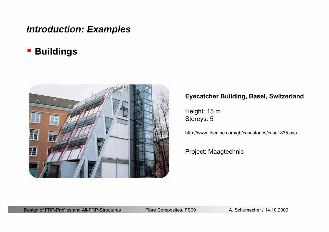
Design of FRP-Profiles and All-FRP-Structures Fibre Composites FS09 A Schumacher 14102009
Introduction Examples
Buildings
Eyecatcher Building Basel Switzerland
Height 15 mStoreys 5
httpwwwfiberlinecomgbcasestoriescase1835asp
Project Maagtechnic
Design of FRP-Profiles and All-FRP-Structures Fibre Composites FS09 A Schumacher 14102009
Introduction Examples
Laboratory bridgeEmpa Laboratory Bridge Switzerland
Span 19 mWidth 16 mLoad capacity 15 tons
Design of FRP-Profiles and All-FRP-Structures Fibre Composites FS09 A Schumacher 14102009
Introduction Examples
Noise barrier SBB
Goumlschenen Switzerland
Project Maagtechnic
Design of FRP-Profiles and All-FRP-Structures Fibre Composites FS09 A Schumacher 14102009
Introduction Examples
Balconies
Switzerland
Project Maagtechnic
Design of FRP-Profiles and All-FRP-Structures Fibre Composites FS09 A Schumacher 14102009
Introduction Examples
RailingsOensingen Switzerland
Heineken brewery Switzerland
Design of FRP-Profiles and All-FRP-Structures Fibre Composites FS09 A Schumacher 14102009
Introduction Application
Applications where GFRP structures are competitive
Significant corrosion and chemical resistance is required(Food and chemical processing plants cooling towers offshore platforms hellip)
Electromagnetic transparency or electrical insulation is required
Light-weight is cost essential(fast deployment hellip)
Prestige and demonstration objects (eg Novartis Campus Entrance Building)
Photo Prof Th Keller EPFL
Design of FRP-Profiles and All-FRP-Structures Fibre Composites FS09 A Schumacher 14102009
Material
Design of FRP-Profiles and All-FRP-Structures Fibre Composites FS09 A Schumacher 14102009
Only pultruded GFRP profiles will be considered in this lecture
Production of profiles with constant cross-section along the length
High quality
Continuous longitudinal fiber bundles and filament mats
Pultrusion line
Material Pultrusion process
Design of FRP-Profiles and All-FRP-Structures Fibre Composites FS09 A Schumacher 14102009
Material Components
Pultruded profiles contain three primary componentsreinforcement
Matrix
Supplementaryconstituents
polyesterepoxyphenol
polymerisation agentsfillersadditives
Design of FRP-Profiles and All-FRP-Structures Fibre Composites FS09 A Schumacher 14102009
Material Shapes of pultruded profiles
Available Profiles on Stock
Length up to 12 m
Special cross-sections can be designed and ordered(several kilometres are necessary rarr special tools have to be designed)
Design of FRP-Profiles and All-FRP-Structures Fibre Composites FS09 A Schumacher 14102009
Material Durability
Various environmental and load conditions that affect durability of (G)FRPs in terms of strength stiffness fibermatrix interface integrity cracking
watersea waterchemical solutionsprolonged freezingthermal cycling (freeze-thaw)elevated temperature exposureUV radiationcreep and relaxationfatiguefirehellip
Design of FRP-Profiles and All-FRP-Structures Fibre Composites FS09 A Schumacher 14102009
Material Durability
Environmental reduction factor for different FRP systems and exposure conditions
070Aramidepoxy
050Glassepoxy(chemical plants)
085CarbonepoxyAgressive environ
075Aramidepoxyparking garages)
065Glassepoxy(bridges piers
085CarbonepoxyExterior exposure
085Aramidepoxy
075Glassepoxy
095CarbonepoxyInterior exposure
Environ reductionFiber resin typeExposure condition
Design of FRP-Profiles and All-FRP-Structures Fibre Composites FS09 A Schumacher 14102009
Material Durability
GFRP is more susceptible to degradation than CFRP by the following effects
alkaline effects (caution when GFRP in contact with concrete)acid effectssalt effectsfatigueUV radiation
Fire protection is a major (unsolved) issue for (G)FRP structural elements and components
Smoke generation and toxicity must be consideredStrength of GFRP is affected by fatigue loading(more than CFRP)
Design of FRP-Profiles and All-FRP-Structures Fibre Composites FS09 A Schumacher 14102009
Material Manufacturers
GFRP profiles available on stock
In Europe two companies pultrude FRP-Profiles
Fiberline Composites Denmarkwwwfiberlinecom
Fiberline Design Manual (wwwfiberlinedk)rarr helpful tool to design structures
(material properties geometries connections hellip)
Top Glass Italywwwtopglassit
Design of FRP-Profiles and All-FRP-Structures Fibre Composites FS09 A Schumacher 14102009
Material Manufacturers
GFRP profiles available on stock
In North America
Strongwell USAwwwstrongwellcom
Creative Pultrusions USAwwwcreativepultrusionscom
Bedford Reinforced Plastics USAwwwbedfordplasticscom
Design of FRP-Profiles and All-FRP-Structures Fibre Composites FS09 A Schumacher 14102009
Design Concept
Design of FRP-Profiles and All-FRP-Structures Fibre Composites FS09 A Schumacher 14102009
Design Concept Basic Assumptions
Definitions and directions
Design of FRP-Profiles and All-FRP-Structures Fibre Composites FS09 A Schumacher 14102009
Design Concept
Codes
Every manufacturer has its own profile design rarr No European Design Code is available (only EN13706 about testing and notation)
There exists European guidelines EUROCOMP 1996 Design CodeEUROCOMP 1996 Handbook
Fiberline Design Manual is based on Eurocomp 1996
Design concept (according to Eurocodes and Swisscodes)
Partial safety factors
Measured material parameters
Rules for bolted connections
Design of FRP-Profiles and All-FRP-Structures Fibre Composites FS09 A Schumacher 14102009
Design Concept
Concept of Limit State Design (According to Euro Codes and Swiss Codes)
Ultimate limit stress
Ed le Rd
Ed hellip Calculated stress (including load factors) hellip SIA260 261
Rd hellip Rated value of the resistance capability
where
Rk hellip the calculated resistance capability
kd mγ=
RR
Design of FRP-Profiles and All-FRP-Structures Fibre Composites FS09 A Schumacher 14102009
101020Production process
Operating temperature
111116Degree of postcuring
115115225Derivation of mat properties
FiberlineMinMaxDescriptionCoefficient
Design Concept
Reduction coefficient m m1 m2 m3 m4γ γ γ γ γ= sdot sdot sdot
m1γ
m2γ
m3γ
m4γ
mγ mγ
31312580
2510-20 +60
Long-term loadShort-term load
Operatingtemperature degC m4γ
Design of FRP-Profiles and All-FRP-Structures Fibre Composites FS09 A Schumacher 14102009
Design Concept
Serviceability limit states
Ed le Cd
Ed hellip the crucial action effect due to the load cases considered inthe investigated dimensioning situation Typically maximaldeflection response of the structure
Cd hellip corresponding serviceability limit SIA 261
Design of FRP-Profiles and All-FRP-Structures Fibre Composites FS09 A Schumacher 14102009
Design Concept Basic Assumptions
Material Properties stength values (Fiberline Profiles)
Design of FRP-Profiles and All-FRP-Structures Fibre Composites FS09 A Schumacher 14102009
Design Concept Basic Assumptions
Material Properties stiffness values (Fiberline Profiles)
Design of FRP-Profiles and All-FRP-Structures Fibre Composites FS09 A Schumacher 14102009
Design Concept Basic Assumptions
Typical data sheet of a profile (Fiberline I-Profile)
Design of FRP-Profiles and All-FRP-Structures Fibre Composites FS09 A Schumacher 14102009
Bending Beam
Design of FRP-Profiles and All-FRP-Structures Fibre Composites FS09 A Schumacher 14102009
Bending Beam Design of hellip
Calculate bending moments Md and shear forces Qd acting on the profile using the partial coefficient (SIA 260 261)
Ultimate limit state
Bending
Shear
Ak hellip relevant shear area
d max d max 0max
M MW Wy z b
mzy
fσ γ
⎛ ⎞⎜ ⎟⎜ ⎟⎜ ⎟⎜ ⎟⎝ ⎠
deg= + le
d maxmax
kyAy
m
Q fττ γ= le
Design of FRP-Profiles and All-FRP-Structures Fibre Composites FS09 A Schumacher 14102009
Bending Beam Design of hellip
Serviceability limit state
Deflection limit
hellip typically selected between 200 and 400given by SIA 261 or the building owner
hellip calculated including shear deformations
Vibrations
Light-weighted and lsquosoftrsquo structures are susceptible to vibrations (traffic wind the movement of people hellip)
max 1wL αlt
α
maxw
Design of FRP-Profiles and All-FRP-Structures Fibre Composites FS09 A Schumacher 14102009
Bending Beam Timoshenko Theory
Pultruded profiles have a low shear modulus rarr shear deformation must be taken into account
Several bending theories have been published for beams
Euler-Bernoulli theory (1702)
Timoshenko theory (1968)
Higher order beam theory
A simply supported beam with a symmetric cross-section is discussed
Design of FRP-Profiles and All-FRP-Structures Fibre Composites FS09 A Schumacher 14102009
Bending Beam Timoshenko Theory
Cross-sections planeand perpendicular
1 degree of freedom
w
Cross-sections plane butNOT perpendicular
2 degrees of freedom
w and ψ
Cross-sections do NOTremain plane
3+ degrees of freedom
w ψ and hellip
Design of FRP-Profiles and All-FRP-Structures Fibre Composites FS09 A Schumacher 14102009
Bending Beam Euler vs Timoshenko Theory
Kinematic relationships
( )( )
( )
2 0
x x
y
xx xx
yxxy
u y w xu w x
u y w xxuu
y x
ε
ε
=minus sdot=
part= =minus sdotpartpartpart= + =
part part
( )( )
( )
2 ( ) ( )
x
y
xx x
yxxy x
u y xu w x
u y xxuu x w xy x
ψ
ε ψ
ε ψ
=minus sdot=
part= =minus sdotpartpartpart= + =minus +
part part
Hookrsquos law
0degE and G 2x x xy xyσ ε τ ε= sdot = sdot
z0deg E Iz x xxQS
M y dydz wσ= minus sdot sdot = sdot sdotintint
( )
z0deg E I
z x xQS
y xQS
M y dydz
Q dydz w GA
σ ψ
κ τ ψ κ
= minus sdot sdot = sdot
= sdot = minus sdot sdot
intint
intint
Design of FRP-Profiles and All-FRP-Structures Fibre Composites FS09 A Schumacher 14102009
Bending Beam Euler vs Timoshenko Theory
Equilibrium
Solution for the simply supported beam (distributed load)
In a first approximation the deflections are calculated by direct integration of
z0deg
( ) E IxxM xw = sdot
( )( )z0deg
( ) E I 0x
x
xx x
xx x
q x w GAw GA
QM Q
ψ κψ ψ κ
minus minus sdot sdot
sdot + minus sdot sdot
=minus =
= =minus
Equilibrium on an infinitesimal beam element
Coupled second order differential equation
21 1( ) (0) 0 and ( ) 02 2
M x qLx qx w w L= minus = =
( )3 2 3
0deg z
( ) 224 E Iqxw x L Lx x= sdot minus +sdot sdot
2
0deg z
1 1 1E I 2 2xxw qLx qx⎛ ⎞= minus⎜ ⎟sdot ⎝ ⎠
(0) 0 and ( ) 0(0) 0 (0) 0 and ( ) 0 ( ) 0 x x
w w LM M L Lψ ψ
= == rarr = = rarr =
Functions4 3 2
1 2 3 4 53 2
1 2 3 4
( )
( )
w x A x A x A x A x A
x B x B x B x Bψ
= + + + +
= + + +
Design of FRP-Profiles and All-FRP-Structures Fibre Composites FS09 A Schumacher 14102009
Put in and solve for the coefficients rarr
Bending Beam Euler vs Timoshenko Theory
Use the boundary conditions and the second differential eq to calculate A1 ndash A5
( )0deg z E I 0xx xw GAψ ψ κsdot + minus sdot sdot =
1 01 1 3 3
2 02 2 4 4
24 E I4 2GA
6 E I3 GA
z
z
AB A B A
AB A B A
κ
κ
deg
deg
sdot= minus = minus minus
sdotsdot
= minus = minus minussdot
( ) ( )( )2 2
0
( )2 GA 24 E Iz
qx L x L Lx xqx L xw x
κ deg
minus + minusminus= +
sdot sdot sdot
Deflection at midspan
4
0
52 384 E Iz
qLLw⎛ ⎞⎜ ⎟⎝ ⎠
deg
sdot= sdot4 2
0
52 384 E I 8 GAz
qL q LLw κ⎛ ⎞ +⎜ ⎟⎝ ⎠
deg
sdot sdot= sdot sdot sdot
Design of FRP-Profiles and All-FRP-Structures Fibre Composites FS09 A Schumacher 14102009
General expression for the total beam deflection as a sum of the deflection due to bending and shear
GAxf
IExfxwz sdot+=
deg κ)()()( 2
0
1
Cantilever beam
Simply supported
Concentrated load (P)
Uniformly distr load (q)
Concentrated load (P)
Uniformly distr load (q)
Beam )( max1 wf
3845 4qLsdot
48
3PL
8
4qL
3
3PL
)( max1 wf
8
2qL
4PL
2
2qL
PL
)( maxwx
2L
2L
L
L
Bending Beam Euler vs Timoshenko Theory
Design of FRP-Profiles and All-FRP-Structures Fibre Composites FS09 A Schumacher 14102009
Bending Beam Euler vs Timoshenko Theory
Example influence of the shear deformation
Profile 300 x 150 mm I-beam
Load uniformly distributed
General rule of thumbfor GFRP beams withspandepth gt 25 sheardeformation can beignored
Design of FRP-Profiles and All-FRP-Structures Fibre Composites FS09 A Schumacher 14102009
Bending Beam Example
Choose an appropriate Profile for the following specifications
1 Deflections and loading
=
=
==
1300 rarr wmax=001 mwmaxL
10 kNmqdser
13 kNmqduls
30 mL
max
4 2
0
5384 E I 8 GA
d ser d serz
q L q Lw κ+
deg
sdot sdot= sdot sdot sdot
2
maxz8 2 I
d ulsq L hσ sdot= sdot
maxky
12 Ad ulsq L
τ sdot=
Design of FRP-Profiles and All-FRP-Structures Fibre Composites FS09 A Schumacher 14102009
Bending Beam Example
2 Find a profile with sufficient bending stiffness
Shear deformations are neglected in a first step
rarr from specification table choose I 240x120x12 rarr
3 Check the bending and shear stresses
6 24
0 max
1054 10 Nm5
E I 384d ser
zq Lwdeg = sdot
sdotsdotge
6 20 1369 10 NmE Izdeg = sdot
2
maxz
358 MPa8 2 Id ulsq L hσ sdot= =sdot
max
ky
1 71 MPa2 Ad ulsq L
τ sdot= =
0 185 MPab df degle =
20 MPadfτle =
Design of FRP-Profiles and All-FRP-Structures Fibre Composites FS09 A Schumacher 14102009
Bending Beam Example
m10398384
5 32
0
4
maxminus
deg
sdot=sdotsdotsdot
+sdot
sdot=
GALq
IELq
w serd
z
serd
κ
4 Check deflection (including shear deformation)
5 Remarks
The design of GFRP-profiles is mostly driven by serviceability criteria
Start the design iteration procedure using the maximal deflection criterion
max 001 mwle =
m10198384
5 32
0
4
maxminus
deg
sdot=sdot
sdot+
sdotsdot
=web
serd
z
serd
GALq
IELq
w
(77 mm) (16 mm)
Design of FRP-Profiles and All-FRP-Structures Fibre Composites FS09 A Schumacher 14102009
Bending Beam Stability problems
Lateral-torsional bucklingFlange (compressive) displace laterally to the transverse load direction
Torsional stiffness is too low (especially for open section profiles)
Theoretical calculations or design measuresrarr see eg LP Kollaacuter 2003
Mechanics of composite structuresExample
Compressive flanges are kept in place by connection to the bridge deck
Design of FRP-Profiles and All-FRP-Structures Fibre Composites FS09 A Schumacher 14102009
Bending Beam Stability problems
Flange (compressive) displaces in the direction of the transverse load
Low bending stiffness perpendicular to the pultrusion direction
Weak fiber mats
Local buckling of walls due to in-plane compression
Local buckling of walls due to in-plane shear
Web crushing and web buckling in transverse direction
Design of FRP-Profiles and All-FRP-Structures Fibre Composites FS09 A Schumacher 14102009
Axial Members
Design of FRP-Profiles and All-FRP-Structures Fibre Composites FS09 A Schumacher 14102009
Axial Members Tension
Ultimate limit state under axial tension Nd
Serviceability limit state
Remark The critical aspect of axial members in tension are neither the serviceability nor the ultimate limit state Critical is the load transfer to the GFRP profile
0NdA
tm
fγ
degle
0deg
N LE Axδ sdot= sdot
Design of FRP-Profiles and All-FRP-Structures Fibre Composites FS09 A Schumacher 14102009
Axial Members Compression
Ultimate limit state under axial compression Nd
hellip maximal compressive load
hellip Euler load
hellip Buckling length for columns
hellip coefficient for Youngrsquos modulus = 13
cc
Euler
FNd F1 N
le+
c0degC
A fF
mγsdot
=
20
Euler 2
Nm E k
E IL
πγ
degsdot sdot=
sdot
kL
m Eγ
Design of FRP-Profiles and All-FRP-Structures Fibre Composites FS09 A Schumacher 14102009
Axial Members Compression
The influence of shear deformation should be considered but in the most cases the influence will be small (less than 5)
Local buckling should be considered for short columns
For more information on the various buckling modes and effects rarr see LP Kollaacuter 2003 Mechanics of composite structures
Global buckling Local buckling
Design of FRP-Profiles and All-FRP-Structures Fibre Composites FS09 A Schumacher 14102009
Connections
Design of FRP-Profiles and All-FRP-Structures Fibre Composites FS09 A Schumacher 14102009
Connections Introduction
Design of FRP-Profiles and All-FRP-Structures Fibre Composites FS09 A Schumacher 14102009
Connections Introduction
(from Eurocomp Design Code 1996)
Design of FRP-Profiles and All-FRP-Structures Fibre Composites FS09 A Schumacher 14102009
Connections Bolted joints
Bolts = Stress concentration in the profile and the bolt
It is necessary to ensure that the bolts and the profilecan withstand this concentrated local stress compression
It is necessary to ensure that the region surroundinga group of bolts will not be torn out of the profile
Basic failure modesin bolted shearconnections
bolt shear failure
Design of FRP-Profiles and All-FRP-Structures Fibre Composites FS09 A Schumacher 14102009
Connections Bolted joints
The design procedure is comparable to the one for steel connections but since there exist no standard GFRP material rarr each manufacturer has its own design rules for bolted joints
IMPORTANT REMARKS
The direction of pultrusion and the direction of the force is RELEVANT(anisotropic material)
Use stainless or galvanised steel
Do not cut threads in the composite material
Use screws with shafts
Design of FRP-Profiles and All-FRP-Structures Fibre Composites FS09 A Schumacher 14102009
Calculation of load bearing capacity of bolts
Shear in longitudinal direction (0deg)
Shear in transverse direction (90deg)
Tensile force
Minimum distances
Connections Bolted joints (Fiberline recommendations)
Design of FRP-Profiles and All-FRP-Structures Fibre Composites FS09 A Schumacher 14102009
Joint capacity tables available for shear and tension
m
150 MPa( 13)B d
d tP γsdot sdot=
=
Shear in longitudinal direction 0deg
m
70 MPa( 13)B d
d tP γsdot sdot=
=
Shear in transverse direction 90deg
Connections Bolted joints (Fiberline recommendations)
Design of FRP-Profiles and All-FRP-Structures Fibre Composites FS09 A Schumacher 14102009
Bolted connection in shear eg shear in longitudinal direction
Connections Bolted joints (Fiberline recommendations)
γmPBolt le dt720 MPaγmPBolt le dt240 MPa
γmPBolt le dt240 MPa γmPBolt le dt240 MPaγmPBolt le dt150 MPa
Design of FRP-Profiles and All-FRP-Structures Fibre Composites FS09 A Schumacher 14102009
Bolted connections in tension
Static conditions
Bolt Tearing of bolt in threaded cross-section
Laminate Shear fracture at rim of washer
Geometry and strength
Diameter of washer2d
Tensile strength of bolt hellipfyk
Shear strength of laminatehellipfτ
Thickness of laminatet
Stress area of the boltAs
Diameter of the boltd
s ykd m
A fP γ
sdotle
2d m
d t fP τπγ
sdot sdot sdot sdotle
Connections Bolted joints (Fiberline recommendations)
Design of FRP-Profiles and All-FRP-Structures Fibre Composites FS09 A Schumacher 14102009
Connections Bonded joints
Using an adhesive agent for joining profiles can have advantages
Easy to use easy to make aesthetic joints
Typically more rigid than bolted joints
Glued joints subjected to dynamic loads are good
But be careful hellipAdhesive agents have properties that depend on time temperature humidity hellip
Failure in glued joints takes place suddenly (brittle behaviour)
The load-bearing capacity is not proportional to the area which is glued
The design of bonded joints may be based onAnalytical models for plate-to-plate connections (see Eurocomp 1996 Design Code)
Design guidelines supplemented by testing
Finite element analysis
Design of FRP-Profiles and All-FRP-Structures Fibre Composites FS09 A Schumacher 14102009
Connections Bonded joints
A bonded joint has the following three primary failure modes
adhesive failure
cohesive failure of adhesive
cohesive failure of adherend
The design of any bonded joint shall satisfy the following conditions
allowable shear stress in the adhesive is not exceeded
allowable tensile (peel) stress in the adhesive is not exceeded
allowable through-thickness tensile stress of the adhesive is not exceeded
allowable in-plane shear stress of the adherend should not be exceeded
The calculation of the stresses has to be done very carefully Often calculations are supplemented by testing
Design of FRP-Profiles and All-FRP-Structures Fibre Composites FS09 A Schumacher 14102009
Connections Bonded joints
Different types of bonded joint configurations
Research on bonded joints for structuralapplications
Design of FRP-Profiles and All-FRP-Structures Fibre Composites FS09 A Schumacher 14102009
Connections Other joints
Brackets for assembly (Fiberline)
Custom pultruded connections
Design of FRP-Profiles and All-FRP-Structures Fibre Composites FS09 A Schumacher 14102009
GFRP Some final remarks
Perpendicular to the direction of pultrusion the material is WEAK and SOFTrarr avoid such loadings if possible
In order to use pultruded GFRP-profiles economically the design must be done in a clever way eg for bridges the railings should be used as part of the load-bearing structure
GFRP structures are very light rarr vibration problems may occur
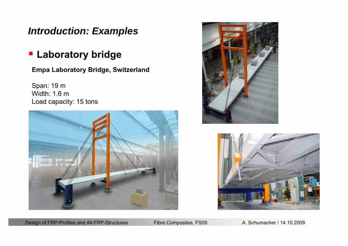
Design of FRP-Profiles and All-FRP-Structures Fibre Composites FS09 A Schumacher 14102009
Introduction Examples
Laboratory bridgeEmpa Laboratory Bridge Switzerland
Span 19 mWidth 16 mLoad capacity 15 tons
Design of FRP-Profiles and All-FRP-Structures Fibre Composites FS09 A Schumacher 14102009
Introduction Examples
Noise barrier SBB
Goumlschenen Switzerland
Project Maagtechnic
Design of FRP-Profiles and All-FRP-Structures Fibre Composites FS09 A Schumacher 14102009
Introduction Examples
Balconies
Switzerland
Project Maagtechnic
Design of FRP-Profiles and All-FRP-Structures Fibre Composites FS09 A Schumacher 14102009
Introduction Examples
RailingsOensingen Switzerland
Heineken brewery Switzerland
Design of FRP-Profiles and All-FRP-Structures Fibre Composites FS09 A Schumacher 14102009
Introduction Application
Applications where GFRP structures are competitive
Significant corrosion and chemical resistance is required(Food and chemical processing plants cooling towers offshore platforms hellip)
Electromagnetic transparency or electrical insulation is required
Light-weight is cost essential(fast deployment hellip)
Prestige and demonstration objects (eg Novartis Campus Entrance Building)
Photo Prof Th Keller EPFL
Design of FRP-Profiles and All-FRP-Structures Fibre Composites FS09 A Schumacher 14102009
Material
Design of FRP-Profiles and All-FRP-Structures Fibre Composites FS09 A Schumacher 14102009
Only pultruded GFRP profiles will be considered in this lecture
Production of profiles with constant cross-section along the length
High quality
Continuous longitudinal fiber bundles and filament mats
Pultrusion line
Material Pultrusion process
Design of FRP-Profiles and All-FRP-Structures Fibre Composites FS09 A Schumacher 14102009
Material Components
Pultruded profiles contain three primary componentsreinforcement
Matrix
Supplementaryconstituents
polyesterepoxyphenol
polymerisation agentsfillersadditives
Design of FRP-Profiles and All-FRP-Structures Fibre Composites FS09 A Schumacher 14102009
Material Shapes of pultruded profiles
Available Profiles on Stock
Length up to 12 m
Special cross-sections can be designed and ordered(several kilometres are necessary rarr special tools have to be designed)
Design of FRP-Profiles and All-FRP-Structures Fibre Composites FS09 A Schumacher 14102009
Material Durability
Various environmental and load conditions that affect durability of (G)FRPs in terms of strength stiffness fibermatrix interface integrity cracking
watersea waterchemical solutionsprolonged freezingthermal cycling (freeze-thaw)elevated temperature exposureUV radiationcreep and relaxationfatiguefirehellip
Design of FRP-Profiles and All-FRP-Structures Fibre Composites FS09 A Schumacher 14102009
Material Durability
Environmental reduction factor for different FRP systems and exposure conditions
070Aramidepoxy
050Glassepoxy(chemical plants)
085CarbonepoxyAgressive environ
075Aramidepoxyparking garages)
065Glassepoxy(bridges piers
085CarbonepoxyExterior exposure
085Aramidepoxy
075Glassepoxy
095CarbonepoxyInterior exposure
Environ reductionFiber resin typeExposure condition
Design of FRP-Profiles and All-FRP-Structures Fibre Composites FS09 A Schumacher 14102009
Material Durability
GFRP is more susceptible to degradation than CFRP by the following effects
alkaline effects (caution when GFRP in contact with concrete)acid effectssalt effectsfatigueUV radiation
Fire protection is a major (unsolved) issue for (G)FRP structural elements and components
Smoke generation and toxicity must be consideredStrength of GFRP is affected by fatigue loading(more than CFRP)
Design of FRP-Profiles and All-FRP-Structures Fibre Composites FS09 A Schumacher 14102009
Material Manufacturers
GFRP profiles available on stock
In Europe two companies pultrude FRP-Profiles
Fiberline Composites Denmarkwwwfiberlinecom
Fiberline Design Manual (wwwfiberlinedk)rarr helpful tool to design structures
(material properties geometries connections hellip)
Top Glass Italywwwtopglassit
Design of FRP-Profiles and All-FRP-Structures Fibre Composites FS09 A Schumacher 14102009
Material Manufacturers
GFRP profiles available on stock
In North America
Strongwell USAwwwstrongwellcom
Creative Pultrusions USAwwwcreativepultrusionscom
Bedford Reinforced Plastics USAwwwbedfordplasticscom
Design of FRP-Profiles and All-FRP-Structures Fibre Composites FS09 A Schumacher 14102009
Design Concept
Design of FRP-Profiles and All-FRP-Structures Fibre Composites FS09 A Schumacher 14102009
Design Concept Basic Assumptions
Definitions and directions
Design of FRP-Profiles and All-FRP-Structures Fibre Composites FS09 A Schumacher 14102009
Design Concept
Codes
Every manufacturer has its own profile design rarr No European Design Code is available (only EN13706 about testing and notation)
There exists European guidelines EUROCOMP 1996 Design CodeEUROCOMP 1996 Handbook
Fiberline Design Manual is based on Eurocomp 1996
Design concept (according to Eurocodes and Swisscodes)
Partial safety factors
Measured material parameters
Rules for bolted connections
Design of FRP-Profiles and All-FRP-Structures Fibre Composites FS09 A Schumacher 14102009
Design Concept
Concept of Limit State Design (According to Euro Codes and Swiss Codes)
Ultimate limit stress
Ed le Rd
Ed hellip Calculated stress (including load factors) hellip SIA260 261
Rd hellip Rated value of the resistance capability
where
Rk hellip the calculated resistance capability
kd mγ=
RR
Design of FRP-Profiles and All-FRP-Structures Fibre Composites FS09 A Schumacher 14102009
101020Production process
Operating temperature
111116Degree of postcuring
115115225Derivation of mat properties
FiberlineMinMaxDescriptionCoefficient
Design Concept
Reduction coefficient m m1 m2 m3 m4γ γ γ γ γ= sdot sdot sdot
m1γ
m2γ
m3γ
m4γ
mγ mγ
31312580
2510-20 +60
Long-term loadShort-term load
Operatingtemperature degC m4γ
Design of FRP-Profiles and All-FRP-Structures Fibre Composites FS09 A Schumacher 14102009
Design Concept
Serviceability limit states
Ed le Cd
Ed hellip the crucial action effect due to the load cases considered inthe investigated dimensioning situation Typically maximaldeflection response of the structure
Cd hellip corresponding serviceability limit SIA 261
Design of FRP-Profiles and All-FRP-Structures Fibre Composites FS09 A Schumacher 14102009
Design Concept Basic Assumptions
Material Properties stength values (Fiberline Profiles)
Design of FRP-Profiles and All-FRP-Structures Fibre Composites FS09 A Schumacher 14102009
Design Concept Basic Assumptions
Material Properties stiffness values (Fiberline Profiles)
Design of FRP-Profiles and All-FRP-Structures Fibre Composites FS09 A Schumacher 14102009
Design Concept Basic Assumptions
Typical data sheet of a profile (Fiberline I-Profile)
Design of FRP-Profiles and All-FRP-Structures Fibre Composites FS09 A Schumacher 14102009
Bending Beam
Design of FRP-Profiles and All-FRP-Structures Fibre Composites FS09 A Schumacher 14102009
Bending Beam Design of hellip
Calculate bending moments Md and shear forces Qd acting on the profile using the partial coefficient (SIA 260 261)
Ultimate limit state
Bending
Shear
Ak hellip relevant shear area
d max d max 0max
M MW Wy z b
mzy
fσ γ
⎛ ⎞⎜ ⎟⎜ ⎟⎜ ⎟⎜ ⎟⎝ ⎠
deg= + le
d maxmax
kyAy
m
Q fττ γ= le
Design of FRP-Profiles and All-FRP-Structures Fibre Composites FS09 A Schumacher 14102009
Bending Beam Design of hellip
Serviceability limit state
Deflection limit
hellip typically selected between 200 and 400given by SIA 261 or the building owner
hellip calculated including shear deformations
Vibrations
Light-weighted and lsquosoftrsquo structures are susceptible to vibrations (traffic wind the movement of people hellip)
max 1wL αlt
α
maxw
Design of FRP-Profiles and All-FRP-Structures Fibre Composites FS09 A Schumacher 14102009
Bending Beam Timoshenko Theory
Pultruded profiles have a low shear modulus rarr shear deformation must be taken into account
Several bending theories have been published for beams
Euler-Bernoulli theory (1702)
Timoshenko theory (1968)
Higher order beam theory
A simply supported beam with a symmetric cross-section is discussed
Design of FRP-Profiles and All-FRP-Structures Fibre Composites FS09 A Schumacher 14102009
Bending Beam Timoshenko Theory
Cross-sections planeand perpendicular
1 degree of freedom
w
Cross-sections plane butNOT perpendicular
2 degrees of freedom
w and ψ
Cross-sections do NOTremain plane
3+ degrees of freedom
w ψ and hellip
Design of FRP-Profiles and All-FRP-Structures Fibre Composites FS09 A Schumacher 14102009
Bending Beam Euler vs Timoshenko Theory
Kinematic relationships
( )( )
( )
2 0
x x
y
xx xx
yxxy
u y w xu w x
u y w xxuu
y x
ε
ε
=minus sdot=
part= =minus sdotpartpartpart= + =
part part
( )( )
( )
2 ( ) ( )
x
y
xx x
yxxy x
u y xu w x
u y xxuu x w xy x
ψ
ε ψ
ε ψ
=minus sdot=
part= =minus sdotpartpartpart= + =minus +
part part
Hookrsquos law
0degE and G 2x x xy xyσ ε τ ε= sdot = sdot
z0deg E Iz x xxQS
M y dydz wσ= minus sdot sdot = sdot sdotintint
( )
z0deg E I
z x xQS
y xQS
M y dydz
Q dydz w GA
σ ψ
κ τ ψ κ
= minus sdot sdot = sdot
= sdot = minus sdot sdot
intint
intint
Design of FRP-Profiles and All-FRP-Structures Fibre Composites FS09 A Schumacher 14102009
Bending Beam Euler vs Timoshenko Theory
Equilibrium
Solution for the simply supported beam (distributed load)
In a first approximation the deflections are calculated by direct integration of
z0deg
( ) E IxxM xw = sdot
( )( )z0deg
( ) E I 0x
x
xx x
xx x
q x w GAw GA
QM Q
ψ κψ ψ κ
minus minus sdot sdot
sdot + minus sdot sdot
=minus =
= =minus
Equilibrium on an infinitesimal beam element
Coupled second order differential equation
21 1( ) (0) 0 and ( ) 02 2
M x qLx qx w w L= minus = =
( )3 2 3
0deg z
( ) 224 E Iqxw x L Lx x= sdot minus +sdot sdot
2
0deg z
1 1 1E I 2 2xxw qLx qx⎛ ⎞= minus⎜ ⎟sdot ⎝ ⎠
(0) 0 and ( ) 0(0) 0 (0) 0 and ( ) 0 ( ) 0 x x
w w LM M L Lψ ψ
= == rarr = = rarr =
Functions4 3 2
1 2 3 4 53 2
1 2 3 4
( )
( )
w x A x A x A x A x A
x B x B x B x Bψ
= + + + +
= + + +
Design of FRP-Profiles and All-FRP-Structures Fibre Composites FS09 A Schumacher 14102009
Put in and solve for the coefficients rarr
Bending Beam Euler vs Timoshenko Theory
Use the boundary conditions and the second differential eq to calculate A1 ndash A5
( )0deg z E I 0xx xw GAψ ψ κsdot + minus sdot sdot =
1 01 1 3 3
2 02 2 4 4
24 E I4 2GA
6 E I3 GA
z
z
AB A B A
AB A B A
κ
κ
deg
deg
sdot= minus = minus minus
sdotsdot
= minus = minus minussdot
( ) ( )( )2 2
0
( )2 GA 24 E Iz
qx L x L Lx xqx L xw x
κ deg
minus + minusminus= +
sdot sdot sdot
Deflection at midspan
4
0
52 384 E Iz
qLLw⎛ ⎞⎜ ⎟⎝ ⎠
deg
sdot= sdot4 2
0
52 384 E I 8 GAz
qL q LLw κ⎛ ⎞ +⎜ ⎟⎝ ⎠
deg
sdot sdot= sdot sdot sdot
Design of FRP-Profiles and All-FRP-Structures Fibre Composites FS09 A Schumacher 14102009
General expression for the total beam deflection as a sum of the deflection due to bending and shear
GAxf
IExfxwz sdot+=
deg κ)()()( 2
0
1
Cantilever beam
Simply supported
Concentrated load (P)
Uniformly distr load (q)
Concentrated load (P)
Uniformly distr load (q)
Beam )( max1 wf
3845 4qLsdot
48
3PL
8
4qL
3
3PL
)( max1 wf
8
2qL
4PL
2
2qL
PL
)( maxwx
2L
2L
L
L
Bending Beam Euler vs Timoshenko Theory
Design of FRP-Profiles and All-FRP-Structures Fibre Composites FS09 A Schumacher 14102009
Bending Beam Euler vs Timoshenko Theory
Example influence of the shear deformation
Profile 300 x 150 mm I-beam
Load uniformly distributed
General rule of thumbfor GFRP beams withspandepth gt 25 sheardeformation can beignored
Design of FRP-Profiles and All-FRP-Structures Fibre Composites FS09 A Schumacher 14102009
Bending Beam Example
Choose an appropriate Profile for the following specifications
1 Deflections and loading
=
=
==
1300 rarr wmax=001 mwmaxL
10 kNmqdser
13 kNmqduls
30 mL
max
4 2
0
5384 E I 8 GA
d ser d serz
q L q Lw κ+
deg
sdot sdot= sdot sdot sdot
2
maxz8 2 I
d ulsq L hσ sdot= sdot
maxky
12 Ad ulsq L
τ sdot=
Design of FRP-Profiles and All-FRP-Structures Fibre Composites FS09 A Schumacher 14102009
Bending Beam Example
2 Find a profile with sufficient bending stiffness
Shear deformations are neglected in a first step
rarr from specification table choose I 240x120x12 rarr
3 Check the bending and shear stresses
6 24
0 max
1054 10 Nm5
E I 384d ser
zq Lwdeg = sdot
sdotsdotge
6 20 1369 10 NmE Izdeg = sdot
2
maxz
358 MPa8 2 Id ulsq L hσ sdot= =sdot
max
ky
1 71 MPa2 Ad ulsq L
τ sdot= =
0 185 MPab df degle =
20 MPadfτle =
Design of FRP-Profiles and All-FRP-Structures Fibre Composites FS09 A Schumacher 14102009
Bending Beam Example
m10398384
5 32
0
4
maxminus
deg
sdot=sdotsdotsdot
+sdot
sdot=
GALq
IELq
w serd
z
serd
κ
4 Check deflection (including shear deformation)
5 Remarks
The design of GFRP-profiles is mostly driven by serviceability criteria
Start the design iteration procedure using the maximal deflection criterion
max 001 mwle =
m10198384
5 32
0
4
maxminus
deg
sdot=sdot
sdot+
sdotsdot
=web
serd
z
serd
GALq
IELq
w
(77 mm) (16 mm)
Design of FRP-Profiles and All-FRP-Structures Fibre Composites FS09 A Schumacher 14102009
Bending Beam Stability problems
Lateral-torsional bucklingFlange (compressive) displace laterally to the transverse load direction
Torsional stiffness is too low (especially for open section profiles)
Theoretical calculations or design measuresrarr see eg LP Kollaacuter 2003
Mechanics of composite structuresExample
Compressive flanges are kept in place by connection to the bridge deck
Design of FRP-Profiles and All-FRP-Structures Fibre Composites FS09 A Schumacher 14102009
Bending Beam Stability problems
Flange (compressive) displaces in the direction of the transverse load
Low bending stiffness perpendicular to the pultrusion direction
Weak fiber mats
Local buckling of walls due to in-plane compression
Local buckling of walls due to in-plane shear
Web crushing and web buckling in transverse direction
Design of FRP-Profiles and All-FRP-Structures Fibre Composites FS09 A Schumacher 14102009
Axial Members
Design of FRP-Profiles and All-FRP-Structures Fibre Composites FS09 A Schumacher 14102009
Axial Members Tension
Ultimate limit state under axial tension Nd
Serviceability limit state
Remark The critical aspect of axial members in tension are neither the serviceability nor the ultimate limit state Critical is the load transfer to the GFRP profile
0NdA
tm
fγ
degle
0deg
N LE Axδ sdot= sdot
Design of FRP-Profiles and All-FRP-Structures Fibre Composites FS09 A Schumacher 14102009
Axial Members Compression
Ultimate limit state under axial compression Nd
hellip maximal compressive load
hellip Euler load
hellip Buckling length for columns
hellip coefficient for Youngrsquos modulus = 13
cc
Euler
FNd F1 N
le+
c0degC
A fF
mγsdot
=
20
Euler 2
Nm E k
E IL
πγ
degsdot sdot=
sdot
kL
m Eγ
Design of FRP-Profiles and All-FRP-Structures Fibre Composites FS09 A Schumacher 14102009
Axial Members Compression
The influence of shear deformation should be considered but in the most cases the influence will be small (less than 5)
Local buckling should be considered for short columns
For more information on the various buckling modes and effects rarr see LP Kollaacuter 2003 Mechanics of composite structures
Global buckling Local buckling
Design of FRP-Profiles and All-FRP-Structures Fibre Composites FS09 A Schumacher 14102009
Connections
Design of FRP-Profiles and All-FRP-Structures Fibre Composites FS09 A Schumacher 14102009
Connections Introduction
Design of FRP-Profiles and All-FRP-Structures Fibre Composites FS09 A Schumacher 14102009
Connections Introduction
(from Eurocomp Design Code 1996)
Design of FRP-Profiles and All-FRP-Structures Fibre Composites FS09 A Schumacher 14102009
Connections Bolted joints
Bolts = Stress concentration in the profile and the bolt
It is necessary to ensure that the bolts and the profilecan withstand this concentrated local stress compression
It is necessary to ensure that the region surroundinga group of bolts will not be torn out of the profile
Basic failure modesin bolted shearconnections
bolt shear failure
Design of FRP-Profiles and All-FRP-Structures Fibre Composites FS09 A Schumacher 14102009
Connections Bolted joints
The design procedure is comparable to the one for steel connections but since there exist no standard GFRP material rarr each manufacturer has its own design rules for bolted joints
IMPORTANT REMARKS
The direction of pultrusion and the direction of the force is RELEVANT(anisotropic material)
Use stainless or galvanised steel
Do not cut threads in the composite material
Use screws with shafts
Design of FRP-Profiles and All-FRP-Structures Fibre Composites FS09 A Schumacher 14102009
Calculation of load bearing capacity of bolts
Shear in longitudinal direction (0deg)
Shear in transverse direction (90deg)
Tensile force
Minimum distances
Connections Bolted joints (Fiberline recommendations)
Design of FRP-Profiles and All-FRP-Structures Fibre Composites FS09 A Schumacher 14102009
Joint capacity tables available for shear and tension
m
150 MPa( 13)B d
d tP γsdot sdot=
=
Shear in longitudinal direction 0deg
m
70 MPa( 13)B d
d tP γsdot sdot=
=
Shear in transverse direction 90deg
Connections Bolted joints (Fiberline recommendations)
Design of FRP-Profiles and All-FRP-Structures Fibre Composites FS09 A Schumacher 14102009
Bolted connection in shear eg shear in longitudinal direction
Connections Bolted joints (Fiberline recommendations)
γmPBolt le dt720 MPaγmPBolt le dt240 MPa
γmPBolt le dt240 MPa γmPBolt le dt240 MPaγmPBolt le dt150 MPa
Design of FRP-Profiles and All-FRP-Structures Fibre Composites FS09 A Schumacher 14102009
Bolted connections in tension
Static conditions
Bolt Tearing of bolt in threaded cross-section
Laminate Shear fracture at rim of washer
Geometry and strength
Diameter of washer2d
Tensile strength of bolt hellipfyk
Shear strength of laminatehellipfτ
Thickness of laminatet
Stress area of the boltAs
Diameter of the boltd
s ykd m
A fP γ
sdotle
2d m
d t fP τπγ
sdot sdot sdot sdotle
Connections Bolted joints (Fiberline recommendations)
Design of FRP-Profiles and All-FRP-Structures Fibre Composites FS09 A Schumacher 14102009
Connections Bonded joints
Using an adhesive agent for joining profiles can have advantages
Easy to use easy to make aesthetic joints
Typically more rigid than bolted joints
Glued joints subjected to dynamic loads are good
But be careful hellipAdhesive agents have properties that depend on time temperature humidity hellip
Failure in glued joints takes place suddenly (brittle behaviour)
The load-bearing capacity is not proportional to the area which is glued
The design of bonded joints may be based onAnalytical models for plate-to-plate connections (see Eurocomp 1996 Design Code)
Design guidelines supplemented by testing
Finite element analysis
Design of FRP-Profiles and All-FRP-Structures Fibre Composites FS09 A Schumacher 14102009
Connections Bonded joints
A bonded joint has the following three primary failure modes
adhesive failure
cohesive failure of adhesive
cohesive failure of adherend
The design of any bonded joint shall satisfy the following conditions
allowable shear stress in the adhesive is not exceeded
allowable tensile (peel) stress in the adhesive is not exceeded
allowable through-thickness tensile stress of the adhesive is not exceeded
allowable in-plane shear stress of the adherend should not be exceeded
The calculation of the stresses has to be done very carefully Often calculations are supplemented by testing
Design of FRP-Profiles and All-FRP-Structures Fibre Composites FS09 A Schumacher 14102009
Connections Bonded joints
Different types of bonded joint configurations
Research on bonded joints for structuralapplications
Design of FRP-Profiles and All-FRP-Structures Fibre Composites FS09 A Schumacher 14102009
Connections Other joints
Brackets for assembly (Fiberline)
Custom pultruded connections
Design of FRP-Profiles and All-FRP-Structures Fibre Composites FS09 A Schumacher 14102009
GFRP Some final remarks
Perpendicular to the direction of pultrusion the material is WEAK and SOFTrarr avoid such loadings if possible
In order to use pultruded GFRP-profiles economically the design must be done in a clever way eg for bridges the railings should be used as part of the load-bearing structure
GFRP structures are very light rarr vibration problems may occur
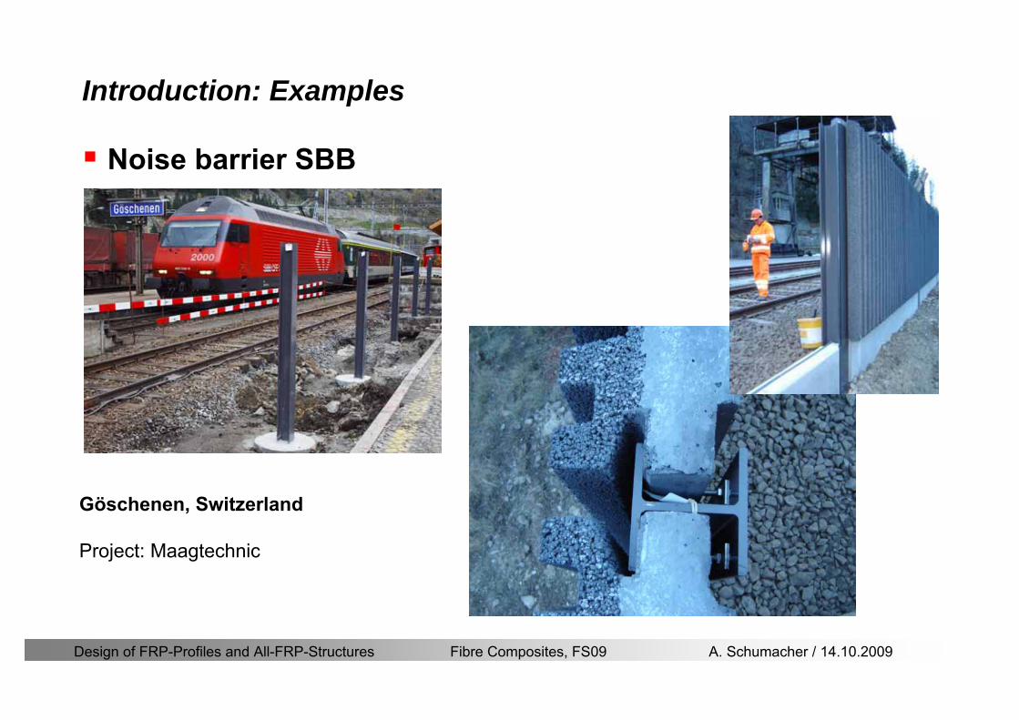
Design of FRP-Profiles and All-FRP-Structures Fibre Composites FS09 A Schumacher 14102009
Introduction Examples
Noise barrier SBB
Goumlschenen Switzerland
Project Maagtechnic
Design of FRP-Profiles and All-FRP-Structures Fibre Composites FS09 A Schumacher 14102009
Introduction Examples
Balconies
Switzerland
Project Maagtechnic
Design of FRP-Profiles and All-FRP-Structures Fibre Composites FS09 A Schumacher 14102009
Introduction Examples
RailingsOensingen Switzerland
Heineken brewery Switzerland
Design of FRP-Profiles and All-FRP-Structures Fibre Composites FS09 A Schumacher 14102009
Introduction Application
Applications where GFRP structures are competitive
Significant corrosion and chemical resistance is required(Food and chemical processing plants cooling towers offshore platforms hellip)
Electromagnetic transparency or electrical insulation is required
Light-weight is cost essential(fast deployment hellip)
Prestige and demonstration objects (eg Novartis Campus Entrance Building)
Photo Prof Th Keller EPFL
Design of FRP-Profiles and All-FRP-Structures Fibre Composites FS09 A Schumacher 14102009
Material
Design of FRP-Profiles and All-FRP-Structures Fibre Composites FS09 A Schumacher 14102009
Only pultruded GFRP profiles will be considered in this lecture
Production of profiles with constant cross-section along the length
High quality
Continuous longitudinal fiber bundles and filament mats
Pultrusion line
Material Pultrusion process
Design of FRP-Profiles and All-FRP-Structures Fibre Composites FS09 A Schumacher 14102009
Material Components
Pultruded profiles contain three primary componentsreinforcement
Matrix
Supplementaryconstituents
polyesterepoxyphenol
polymerisation agentsfillersadditives
Design of FRP-Profiles and All-FRP-Structures Fibre Composites FS09 A Schumacher 14102009
Material Shapes of pultruded profiles
Available Profiles on Stock
Length up to 12 m
Special cross-sections can be designed and ordered(several kilometres are necessary rarr special tools have to be designed)
Design of FRP-Profiles and All-FRP-Structures Fibre Composites FS09 A Schumacher 14102009
Material Durability
Various environmental and load conditions that affect durability of (G)FRPs in terms of strength stiffness fibermatrix interface integrity cracking
watersea waterchemical solutionsprolonged freezingthermal cycling (freeze-thaw)elevated temperature exposureUV radiationcreep and relaxationfatiguefirehellip
Design of FRP-Profiles and All-FRP-Structures Fibre Composites FS09 A Schumacher 14102009
Material Durability
Environmental reduction factor for different FRP systems and exposure conditions
070Aramidepoxy
050Glassepoxy(chemical plants)
085CarbonepoxyAgressive environ
075Aramidepoxyparking garages)
065Glassepoxy(bridges piers
085CarbonepoxyExterior exposure
085Aramidepoxy
075Glassepoxy
095CarbonepoxyInterior exposure
Environ reductionFiber resin typeExposure condition
Design of FRP-Profiles and All-FRP-Structures Fibre Composites FS09 A Schumacher 14102009
Material Durability
GFRP is more susceptible to degradation than CFRP by the following effects
alkaline effects (caution when GFRP in contact with concrete)acid effectssalt effectsfatigueUV radiation
Fire protection is a major (unsolved) issue for (G)FRP structural elements and components
Smoke generation and toxicity must be consideredStrength of GFRP is affected by fatigue loading(more than CFRP)
Design of FRP-Profiles and All-FRP-Structures Fibre Composites FS09 A Schumacher 14102009
Material Manufacturers
GFRP profiles available on stock
In Europe two companies pultrude FRP-Profiles
Fiberline Composites Denmarkwwwfiberlinecom
Fiberline Design Manual (wwwfiberlinedk)rarr helpful tool to design structures
(material properties geometries connections hellip)
Top Glass Italywwwtopglassit
Design of FRP-Profiles and All-FRP-Structures Fibre Composites FS09 A Schumacher 14102009
Material Manufacturers
GFRP profiles available on stock
In North America
Strongwell USAwwwstrongwellcom
Creative Pultrusions USAwwwcreativepultrusionscom
Bedford Reinforced Plastics USAwwwbedfordplasticscom
Design of FRP-Profiles and All-FRP-Structures Fibre Composites FS09 A Schumacher 14102009
Design Concept
Design of FRP-Profiles and All-FRP-Structures Fibre Composites FS09 A Schumacher 14102009
Design Concept Basic Assumptions
Definitions and directions
Design of FRP-Profiles and All-FRP-Structures Fibre Composites FS09 A Schumacher 14102009
Design Concept
Codes
Every manufacturer has its own profile design rarr No European Design Code is available (only EN13706 about testing and notation)
There exists European guidelines EUROCOMP 1996 Design CodeEUROCOMP 1996 Handbook
Fiberline Design Manual is based on Eurocomp 1996
Design concept (according to Eurocodes and Swisscodes)
Partial safety factors
Measured material parameters
Rules for bolted connections
Design of FRP-Profiles and All-FRP-Structures Fibre Composites FS09 A Schumacher 14102009
Design Concept
Concept of Limit State Design (According to Euro Codes and Swiss Codes)
Ultimate limit stress
Ed le Rd
Ed hellip Calculated stress (including load factors) hellip SIA260 261
Rd hellip Rated value of the resistance capability
where
Rk hellip the calculated resistance capability
kd mγ=
RR
Design of FRP-Profiles and All-FRP-Structures Fibre Composites FS09 A Schumacher 14102009
101020Production process
Operating temperature
111116Degree of postcuring
115115225Derivation of mat properties
FiberlineMinMaxDescriptionCoefficient
Design Concept
Reduction coefficient m m1 m2 m3 m4γ γ γ γ γ= sdot sdot sdot
m1γ
m2γ
m3γ
m4γ
mγ mγ
31312580
2510-20 +60
Long-term loadShort-term load
Operatingtemperature degC m4γ
Design of FRP-Profiles and All-FRP-Structures Fibre Composites FS09 A Schumacher 14102009
Design Concept
Serviceability limit states
Ed le Cd
Ed hellip the crucial action effect due to the load cases considered inthe investigated dimensioning situation Typically maximaldeflection response of the structure
Cd hellip corresponding serviceability limit SIA 261
Design of FRP-Profiles and All-FRP-Structures Fibre Composites FS09 A Schumacher 14102009
Design Concept Basic Assumptions
Material Properties stength values (Fiberline Profiles)
Design of FRP-Profiles and All-FRP-Structures Fibre Composites FS09 A Schumacher 14102009
Design Concept Basic Assumptions
Material Properties stiffness values (Fiberline Profiles)
Design of FRP-Profiles and All-FRP-Structures Fibre Composites FS09 A Schumacher 14102009
Design Concept Basic Assumptions
Typical data sheet of a profile (Fiberline I-Profile)
Design of FRP-Profiles and All-FRP-Structures Fibre Composites FS09 A Schumacher 14102009
Bending Beam
Design of FRP-Profiles and All-FRP-Structures Fibre Composites FS09 A Schumacher 14102009
Bending Beam Design of hellip
Calculate bending moments Md and shear forces Qd acting on the profile using the partial coefficient (SIA 260 261)
Ultimate limit state
Bending
Shear
Ak hellip relevant shear area
d max d max 0max
M MW Wy z b
mzy
fσ γ
⎛ ⎞⎜ ⎟⎜ ⎟⎜ ⎟⎜ ⎟⎝ ⎠
deg= + le
d maxmax
kyAy
m
Q fττ γ= le
Design of FRP-Profiles and All-FRP-Structures Fibre Composites FS09 A Schumacher 14102009
Bending Beam Design of hellip
Serviceability limit state
Deflection limit
hellip typically selected between 200 and 400given by SIA 261 or the building owner
hellip calculated including shear deformations
Vibrations
Light-weighted and lsquosoftrsquo structures are susceptible to vibrations (traffic wind the movement of people hellip)
max 1wL αlt
α
maxw
Design of FRP-Profiles and All-FRP-Structures Fibre Composites FS09 A Schumacher 14102009
Bending Beam Timoshenko Theory
Pultruded profiles have a low shear modulus rarr shear deformation must be taken into account
Several bending theories have been published for beams
Euler-Bernoulli theory (1702)
Timoshenko theory (1968)
Higher order beam theory
A simply supported beam with a symmetric cross-section is discussed
Design of FRP-Profiles and All-FRP-Structures Fibre Composites FS09 A Schumacher 14102009
Bending Beam Timoshenko Theory
Cross-sections planeand perpendicular
1 degree of freedom
w
Cross-sections plane butNOT perpendicular
2 degrees of freedom
w and ψ
Cross-sections do NOTremain plane
3+ degrees of freedom
w ψ and hellip
Design of FRP-Profiles and All-FRP-Structures Fibre Composites FS09 A Schumacher 14102009
Bending Beam Euler vs Timoshenko Theory
Kinematic relationships
( )( )
( )
2 0
x x
y
xx xx
yxxy
u y w xu w x
u y w xxuu
y x
ε
ε
=minus sdot=
part= =minus sdotpartpartpart= + =
part part
( )( )
( )
2 ( ) ( )
x
y
xx x
yxxy x
u y xu w x
u y xxuu x w xy x
ψ
ε ψ
ε ψ
=minus sdot=
part= =minus sdotpartpartpart= + =minus +
part part
Hookrsquos law
0degE and G 2x x xy xyσ ε τ ε= sdot = sdot
z0deg E Iz x xxQS
M y dydz wσ= minus sdot sdot = sdot sdotintint
( )
z0deg E I
z x xQS
y xQS
M y dydz
Q dydz w GA
σ ψ
κ τ ψ κ
= minus sdot sdot = sdot
= sdot = minus sdot sdot
intint
intint
Design of FRP-Profiles and All-FRP-Structures Fibre Composites FS09 A Schumacher 14102009
Bending Beam Euler vs Timoshenko Theory
Equilibrium
Solution for the simply supported beam (distributed load)
In a first approximation the deflections are calculated by direct integration of
z0deg
( ) E IxxM xw = sdot
( )( )z0deg
( ) E I 0x
x
xx x
xx x
q x w GAw GA
QM Q
ψ κψ ψ κ
minus minus sdot sdot
sdot + minus sdot sdot
=minus =
= =minus
Equilibrium on an infinitesimal beam element
Coupled second order differential equation
21 1( ) (0) 0 and ( ) 02 2
M x qLx qx w w L= minus = =
( )3 2 3
0deg z
( ) 224 E Iqxw x L Lx x= sdot minus +sdot sdot
2
0deg z
1 1 1E I 2 2xxw qLx qx⎛ ⎞= minus⎜ ⎟sdot ⎝ ⎠
(0) 0 and ( ) 0(0) 0 (0) 0 and ( ) 0 ( ) 0 x x
w w LM M L Lψ ψ
= == rarr = = rarr =
Functions4 3 2
1 2 3 4 53 2
1 2 3 4
( )
( )
w x A x A x A x A x A
x B x B x B x Bψ
= + + + +
= + + +
Design of FRP-Profiles and All-FRP-Structures Fibre Composites FS09 A Schumacher 14102009
Put in and solve for the coefficients rarr
Bending Beam Euler vs Timoshenko Theory
Use the boundary conditions and the second differential eq to calculate A1 ndash A5
( )0deg z E I 0xx xw GAψ ψ κsdot + minus sdot sdot =
1 01 1 3 3
2 02 2 4 4
24 E I4 2GA
6 E I3 GA
z
z
AB A B A
AB A B A
κ
κ
deg
deg
sdot= minus = minus minus
sdotsdot
= minus = minus minussdot
( ) ( )( )2 2
0
( )2 GA 24 E Iz
qx L x L Lx xqx L xw x
κ deg
minus + minusminus= +
sdot sdot sdot
Deflection at midspan
4
0
52 384 E Iz
qLLw⎛ ⎞⎜ ⎟⎝ ⎠
deg
sdot= sdot4 2
0
52 384 E I 8 GAz
qL q LLw κ⎛ ⎞ +⎜ ⎟⎝ ⎠
deg
sdot sdot= sdot sdot sdot
Design of FRP-Profiles and All-FRP-Structures Fibre Composites FS09 A Schumacher 14102009
General expression for the total beam deflection as a sum of the deflection due to bending and shear
GAxf
IExfxwz sdot+=
deg κ)()()( 2
0
1
Cantilever beam
Simply supported
Concentrated load (P)
Uniformly distr load (q)
Concentrated load (P)
Uniformly distr load (q)
Beam )( max1 wf
3845 4qLsdot
48
3PL
8
4qL
3
3PL
)( max1 wf
8
2qL
4PL
2
2qL
PL
)( maxwx
2L
2L
L
L
Bending Beam Euler vs Timoshenko Theory
Design of FRP-Profiles and All-FRP-Structures Fibre Composites FS09 A Schumacher 14102009
Bending Beam Euler vs Timoshenko Theory
Example influence of the shear deformation
Profile 300 x 150 mm I-beam
Load uniformly distributed
General rule of thumbfor GFRP beams withspandepth gt 25 sheardeformation can beignored
Design of FRP-Profiles and All-FRP-Structures Fibre Composites FS09 A Schumacher 14102009
Bending Beam Example
Choose an appropriate Profile for the following specifications
1 Deflections and loading
=
=
==
1300 rarr wmax=001 mwmaxL
10 kNmqdser
13 kNmqduls
30 mL
max
4 2
0
5384 E I 8 GA
d ser d serz
q L q Lw κ+
deg
sdot sdot= sdot sdot sdot
2
maxz8 2 I
d ulsq L hσ sdot= sdot
maxky
12 Ad ulsq L
τ sdot=
Design of FRP-Profiles and All-FRP-Structures Fibre Composites FS09 A Schumacher 14102009
Bending Beam Example
2 Find a profile with sufficient bending stiffness
Shear deformations are neglected in a first step
rarr from specification table choose I 240x120x12 rarr
3 Check the bending and shear stresses
6 24
0 max
1054 10 Nm5
E I 384d ser
zq Lwdeg = sdot
sdotsdotge
6 20 1369 10 NmE Izdeg = sdot
2
maxz
358 MPa8 2 Id ulsq L hσ sdot= =sdot
max
ky
1 71 MPa2 Ad ulsq L
τ sdot= =
0 185 MPab df degle =
20 MPadfτle =
Design of FRP-Profiles and All-FRP-Structures Fibre Composites FS09 A Schumacher 14102009
Bending Beam Example
m10398384
5 32
0
4
maxminus
deg
sdot=sdotsdotsdot
+sdot
sdot=
GALq
IELq
w serd
z
serd
κ
4 Check deflection (including shear deformation)
5 Remarks
The design of GFRP-profiles is mostly driven by serviceability criteria
Start the design iteration procedure using the maximal deflection criterion
max 001 mwle =
m10198384
5 32
0
4
maxminus
deg
sdot=sdot
sdot+
sdotsdot
=web
serd
z
serd
GALq
IELq
w
(77 mm) (16 mm)
Design of FRP-Profiles and All-FRP-Structures Fibre Composites FS09 A Schumacher 14102009
Bending Beam Stability problems
Lateral-torsional bucklingFlange (compressive) displace laterally to the transverse load direction
Torsional stiffness is too low (especially for open section profiles)
Theoretical calculations or design measuresrarr see eg LP Kollaacuter 2003
Mechanics of composite structuresExample
Compressive flanges are kept in place by connection to the bridge deck
Design of FRP-Profiles and All-FRP-Structures Fibre Composites FS09 A Schumacher 14102009
Bending Beam Stability problems
Flange (compressive) displaces in the direction of the transverse load
Low bending stiffness perpendicular to the pultrusion direction
Weak fiber mats
Local buckling of walls due to in-plane compression
Local buckling of walls due to in-plane shear
Web crushing and web buckling in transverse direction
Design of FRP-Profiles and All-FRP-Structures Fibre Composites FS09 A Schumacher 14102009
Axial Members
Design of FRP-Profiles and All-FRP-Structures Fibre Composites FS09 A Schumacher 14102009
Axial Members Tension
Ultimate limit state under axial tension Nd
Serviceability limit state
Remark The critical aspect of axial members in tension are neither the serviceability nor the ultimate limit state Critical is the load transfer to the GFRP profile
0NdA
tm
fγ
degle
0deg
N LE Axδ sdot= sdot
Design of FRP-Profiles and All-FRP-Structures Fibre Composites FS09 A Schumacher 14102009
Axial Members Compression
Ultimate limit state under axial compression Nd
hellip maximal compressive load
hellip Euler load
hellip Buckling length for columns
hellip coefficient for Youngrsquos modulus = 13
cc
Euler
FNd F1 N
le+
c0degC
A fF
mγsdot
=
20
Euler 2
Nm E k
E IL
πγ
degsdot sdot=
sdot
kL
m Eγ
Design of FRP-Profiles and All-FRP-Structures Fibre Composites FS09 A Schumacher 14102009
Axial Members Compression
The influence of shear deformation should be considered but in the most cases the influence will be small (less than 5)
Local buckling should be considered for short columns
For more information on the various buckling modes and effects rarr see LP Kollaacuter 2003 Mechanics of composite structures
Global buckling Local buckling
Design of FRP-Profiles and All-FRP-Structures Fibre Composites FS09 A Schumacher 14102009
Connections
Design of FRP-Profiles and All-FRP-Structures Fibre Composites FS09 A Schumacher 14102009
Connections Introduction
Design of FRP-Profiles and All-FRP-Structures Fibre Composites FS09 A Schumacher 14102009
Connections Introduction
(from Eurocomp Design Code 1996)
Design of FRP-Profiles and All-FRP-Structures Fibre Composites FS09 A Schumacher 14102009
Connections Bolted joints
Bolts = Stress concentration in the profile and the bolt
It is necessary to ensure that the bolts and the profilecan withstand this concentrated local stress compression
It is necessary to ensure that the region surroundinga group of bolts will not be torn out of the profile
Basic failure modesin bolted shearconnections
bolt shear failure
Design of FRP-Profiles and All-FRP-Structures Fibre Composites FS09 A Schumacher 14102009
Connections Bolted joints
The design procedure is comparable to the one for steel connections but since there exist no standard GFRP material rarr each manufacturer has its own design rules for bolted joints
IMPORTANT REMARKS
The direction of pultrusion and the direction of the force is RELEVANT(anisotropic material)
Use stainless or galvanised steel
Do not cut threads in the composite material
Use screws with shafts
Design of FRP-Profiles and All-FRP-Structures Fibre Composites FS09 A Schumacher 14102009
Calculation of load bearing capacity of bolts
Shear in longitudinal direction (0deg)
Shear in transverse direction (90deg)
Tensile force
Minimum distances
Connections Bolted joints (Fiberline recommendations)
Design of FRP-Profiles and All-FRP-Structures Fibre Composites FS09 A Schumacher 14102009
Joint capacity tables available for shear and tension
m
150 MPa( 13)B d
d tP γsdot sdot=
=
Shear in longitudinal direction 0deg
m
70 MPa( 13)B d
d tP γsdot sdot=
=
Shear in transverse direction 90deg
Connections Bolted joints (Fiberline recommendations)
Design of FRP-Profiles and All-FRP-Structures Fibre Composites FS09 A Schumacher 14102009
Bolted connection in shear eg shear in longitudinal direction
Connections Bolted joints (Fiberline recommendations)
γmPBolt le dt720 MPaγmPBolt le dt240 MPa
γmPBolt le dt240 MPa γmPBolt le dt240 MPaγmPBolt le dt150 MPa
Design of FRP-Profiles and All-FRP-Structures Fibre Composites FS09 A Schumacher 14102009
Bolted connections in tension
Static conditions
Bolt Tearing of bolt in threaded cross-section
Laminate Shear fracture at rim of washer
Geometry and strength
Diameter of washer2d
Tensile strength of bolt hellipfyk
Shear strength of laminatehellipfτ
Thickness of laminatet
Stress area of the boltAs
Diameter of the boltd
s ykd m
A fP γ
sdotle
2d m
d t fP τπγ
sdot sdot sdot sdotle
Connections Bolted joints (Fiberline recommendations)
Design of FRP-Profiles and All-FRP-Structures Fibre Composites FS09 A Schumacher 14102009
Connections Bonded joints
Using an adhesive agent for joining profiles can have advantages
Easy to use easy to make aesthetic joints
Typically more rigid than bolted joints
Glued joints subjected to dynamic loads are good
But be careful hellipAdhesive agents have properties that depend on time temperature humidity hellip
Failure in glued joints takes place suddenly (brittle behaviour)
The load-bearing capacity is not proportional to the area which is glued
The design of bonded joints may be based onAnalytical models for plate-to-plate connections (see Eurocomp 1996 Design Code)
Design guidelines supplemented by testing
Finite element analysis
Design of FRP-Profiles and All-FRP-Structures Fibre Composites FS09 A Schumacher 14102009
Connections Bonded joints
A bonded joint has the following three primary failure modes
adhesive failure
cohesive failure of adhesive
cohesive failure of adherend
The design of any bonded joint shall satisfy the following conditions
allowable shear stress in the adhesive is not exceeded
allowable tensile (peel) stress in the adhesive is not exceeded
allowable through-thickness tensile stress of the adhesive is not exceeded
allowable in-plane shear stress of the adherend should not be exceeded
The calculation of the stresses has to be done very carefully Often calculations are supplemented by testing
Design of FRP-Profiles and All-FRP-Structures Fibre Composites FS09 A Schumacher 14102009
Connections Bonded joints
Different types of bonded joint configurations
Research on bonded joints for structuralapplications
Design of FRP-Profiles and All-FRP-Structures Fibre Composites FS09 A Schumacher 14102009
Connections Other joints
Brackets for assembly (Fiberline)
Custom pultruded connections
Design of FRP-Profiles and All-FRP-Structures Fibre Composites FS09 A Schumacher 14102009
GFRP Some final remarks
Perpendicular to the direction of pultrusion the material is WEAK and SOFTrarr avoid such loadings if possible
In order to use pultruded GFRP-profiles economically the design must be done in a clever way eg for bridges the railings should be used as part of the load-bearing structure
GFRP structures are very light rarr vibration problems may occur
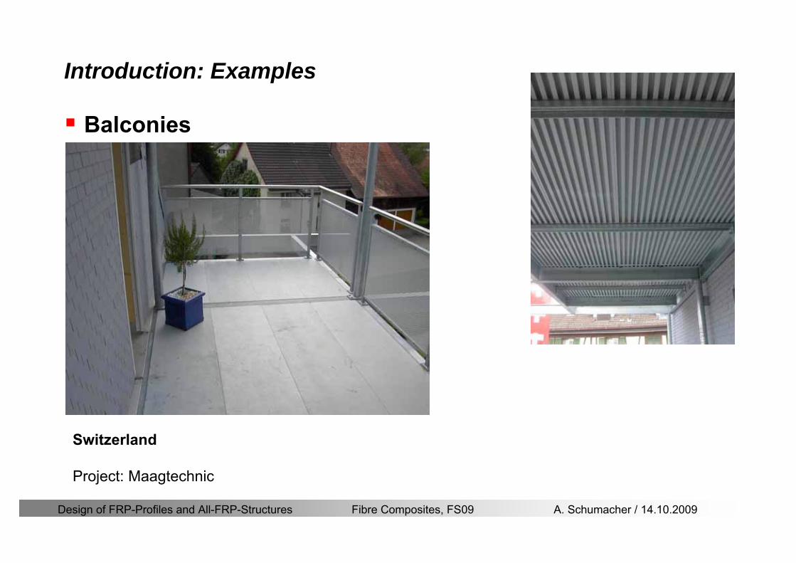
Design of FRP-Profiles and All-FRP-Structures Fibre Composites FS09 A Schumacher 14102009
Introduction Examples
Balconies
Switzerland
Project Maagtechnic
Design of FRP-Profiles and All-FRP-Structures Fibre Composites FS09 A Schumacher 14102009
Introduction Examples
RailingsOensingen Switzerland
Heineken brewery Switzerland
Design of FRP-Profiles and All-FRP-Structures Fibre Composites FS09 A Schumacher 14102009
Introduction Application
Applications where GFRP structures are competitive
Significant corrosion and chemical resistance is required(Food and chemical processing plants cooling towers offshore platforms hellip)
Electromagnetic transparency or electrical insulation is required
Light-weight is cost essential(fast deployment hellip)
Prestige and demonstration objects (eg Novartis Campus Entrance Building)
Photo Prof Th Keller EPFL
Design of FRP-Profiles and All-FRP-Structures Fibre Composites FS09 A Schumacher 14102009
Material
Design of FRP-Profiles and All-FRP-Structures Fibre Composites FS09 A Schumacher 14102009
Only pultruded GFRP profiles will be considered in this lecture
Production of profiles with constant cross-section along the length
High quality
Continuous longitudinal fiber bundles and filament mats
Pultrusion line
Material Pultrusion process
Design of FRP-Profiles and All-FRP-Structures Fibre Composites FS09 A Schumacher 14102009
Material Components
Pultruded profiles contain three primary componentsreinforcement
Matrix
Supplementaryconstituents
polyesterepoxyphenol
polymerisation agentsfillersadditives
Design of FRP-Profiles and All-FRP-Structures Fibre Composites FS09 A Schumacher 14102009
Material Shapes of pultruded profiles
Available Profiles on Stock
Length up to 12 m
Special cross-sections can be designed and ordered(several kilometres are necessary rarr special tools have to be designed)
Design of FRP-Profiles and All-FRP-Structures Fibre Composites FS09 A Schumacher 14102009
Material Durability
Various environmental and load conditions that affect durability of (G)FRPs in terms of strength stiffness fibermatrix interface integrity cracking
watersea waterchemical solutionsprolonged freezingthermal cycling (freeze-thaw)elevated temperature exposureUV radiationcreep and relaxationfatiguefirehellip
Design of FRP-Profiles and All-FRP-Structures Fibre Composites FS09 A Schumacher 14102009
Material Durability
Environmental reduction factor for different FRP systems and exposure conditions
070Aramidepoxy
050Glassepoxy(chemical plants)
085CarbonepoxyAgressive environ
075Aramidepoxyparking garages)
065Glassepoxy(bridges piers
085CarbonepoxyExterior exposure
085Aramidepoxy
075Glassepoxy
095CarbonepoxyInterior exposure
Environ reductionFiber resin typeExposure condition
Design of FRP-Profiles and All-FRP-Structures Fibre Composites FS09 A Schumacher 14102009
Material Durability
GFRP is more susceptible to degradation than CFRP by the following effects
alkaline effects (caution when GFRP in contact with concrete)acid effectssalt effectsfatigueUV radiation
Fire protection is a major (unsolved) issue for (G)FRP structural elements and components
Smoke generation and toxicity must be consideredStrength of GFRP is affected by fatigue loading(more than CFRP)
Design of FRP-Profiles and All-FRP-Structures Fibre Composites FS09 A Schumacher 14102009
Material Manufacturers
GFRP profiles available on stock
In Europe two companies pultrude FRP-Profiles
Fiberline Composites Denmarkwwwfiberlinecom
Fiberline Design Manual (wwwfiberlinedk)rarr helpful tool to design structures
(material properties geometries connections hellip)
Top Glass Italywwwtopglassit
Design of FRP-Profiles and All-FRP-Structures Fibre Composites FS09 A Schumacher 14102009
Material Manufacturers
GFRP profiles available on stock
In North America
Strongwell USAwwwstrongwellcom
Creative Pultrusions USAwwwcreativepultrusionscom
Bedford Reinforced Plastics USAwwwbedfordplasticscom
Design of FRP-Profiles and All-FRP-Structures Fibre Composites FS09 A Schumacher 14102009
Design Concept
Design of FRP-Profiles and All-FRP-Structures Fibre Composites FS09 A Schumacher 14102009
Design Concept Basic Assumptions
Definitions and directions
Design of FRP-Profiles and All-FRP-Structures Fibre Composites FS09 A Schumacher 14102009
Design Concept
Codes
Every manufacturer has its own profile design rarr No European Design Code is available (only EN13706 about testing and notation)
There exists European guidelines EUROCOMP 1996 Design CodeEUROCOMP 1996 Handbook
Fiberline Design Manual is based on Eurocomp 1996
Design concept (according to Eurocodes and Swisscodes)
Partial safety factors
Measured material parameters
Rules for bolted connections
Design of FRP-Profiles and All-FRP-Structures Fibre Composites FS09 A Schumacher 14102009
Design Concept
Concept of Limit State Design (According to Euro Codes and Swiss Codes)
Ultimate limit stress
Ed le Rd
Ed hellip Calculated stress (including load factors) hellip SIA260 261
Rd hellip Rated value of the resistance capability
where
Rk hellip the calculated resistance capability
kd mγ=
RR
Design of FRP-Profiles and All-FRP-Structures Fibre Composites FS09 A Schumacher 14102009
101020Production process
Operating temperature
111116Degree of postcuring
115115225Derivation of mat properties
FiberlineMinMaxDescriptionCoefficient
Design Concept
Reduction coefficient m m1 m2 m3 m4γ γ γ γ γ= sdot sdot sdot
m1γ
m2γ
m3γ
m4γ
mγ mγ
31312580
2510-20 +60
Long-term loadShort-term load
Operatingtemperature degC m4γ
Design of FRP-Profiles and All-FRP-Structures Fibre Composites FS09 A Schumacher 14102009
Design Concept
Serviceability limit states
Ed le Cd
Ed hellip the crucial action effect due to the load cases considered inthe investigated dimensioning situation Typically maximaldeflection response of the structure
Cd hellip corresponding serviceability limit SIA 261
Design of FRP-Profiles and All-FRP-Structures Fibre Composites FS09 A Schumacher 14102009
Design Concept Basic Assumptions
Material Properties stength values (Fiberline Profiles)
Design of FRP-Profiles and All-FRP-Structures Fibre Composites FS09 A Schumacher 14102009
Design Concept Basic Assumptions
Material Properties stiffness values (Fiberline Profiles)
Design of FRP-Profiles and All-FRP-Structures Fibre Composites FS09 A Schumacher 14102009
Design Concept Basic Assumptions
Typical data sheet of a profile (Fiberline I-Profile)
Design of FRP-Profiles and All-FRP-Structures Fibre Composites FS09 A Schumacher 14102009
Bending Beam
Design of FRP-Profiles and All-FRP-Structures Fibre Composites FS09 A Schumacher 14102009
Bending Beam Design of hellip
Calculate bending moments Md and shear forces Qd acting on the profile using the partial coefficient (SIA 260 261)
Ultimate limit state
Bending
Shear
Ak hellip relevant shear area
d max d max 0max
M MW Wy z b
mzy
fσ γ
⎛ ⎞⎜ ⎟⎜ ⎟⎜ ⎟⎜ ⎟⎝ ⎠
deg= + le
d maxmax
kyAy
m
Q fττ γ= le
Design of FRP-Profiles and All-FRP-Structures Fibre Composites FS09 A Schumacher 14102009
Bending Beam Design of hellip
Serviceability limit state
Deflection limit
hellip typically selected between 200 and 400given by SIA 261 or the building owner
hellip calculated including shear deformations
Vibrations
Light-weighted and lsquosoftrsquo structures are susceptible to vibrations (traffic wind the movement of people hellip)
max 1wL αlt
α
maxw
Design of FRP-Profiles and All-FRP-Structures Fibre Composites FS09 A Schumacher 14102009
Bending Beam Timoshenko Theory
Pultruded profiles have a low shear modulus rarr shear deformation must be taken into account
Several bending theories have been published for beams
Euler-Bernoulli theory (1702)
Timoshenko theory (1968)
Higher order beam theory
A simply supported beam with a symmetric cross-section is discussed
Design of FRP-Profiles and All-FRP-Structures Fibre Composites FS09 A Schumacher 14102009
Bending Beam Timoshenko Theory
Cross-sections planeand perpendicular
1 degree of freedom
w
Cross-sections plane butNOT perpendicular
2 degrees of freedom
w and ψ
Cross-sections do NOTremain plane
3+ degrees of freedom
w ψ and hellip
Design of FRP-Profiles and All-FRP-Structures Fibre Composites FS09 A Schumacher 14102009
Bending Beam Euler vs Timoshenko Theory
Kinematic relationships
( )( )
( )
2 0
x x
y
xx xx
yxxy
u y w xu w x
u y w xxuu
y x
ε
ε
=minus sdot=
part= =minus sdotpartpartpart= + =
part part
( )( )
( )
2 ( ) ( )
x
y
xx x
yxxy x
u y xu w x
u y xxuu x w xy x
ψ
ε ψ
ε ψ
=minus sdot=
part= =minus sdotpartpartpart= + =minus +
part part
Hookrsquos law
0degE and G 2x x xy xyσ ε τ ε= sdot = sdot
z0deg E Iz x xxQS
M y dydz wσ= minus sdot sdot = sdot sdotintint
( )
z0deg E I
z x xQS
y xQS
M y dydz
Q dydz w GA
σ ψ
κ τ ψ κ
= minus sdot sdot = sdot
= sdot = minus sdot sdot
intint
intint
Design of FRP-Profiles and All-FRP-Structures Fibre Composites FS09 A Schumacher 14102009
Bending Beam Euler vs Timoshenko Theory
Equilibrium
Solution for the simply supported beam (distributed load)
In a first approximation the deflections are calculated by direct integration of
z0deg
( ) E IxxM xw = sdot
( )( )z0deg
( ) E I 0x
x
xx x
xx x
q x w GAw GA
QM Q
ψ κψ ψ κ
minus minus sdot sdot
sdot + minus sdot sdot
=minus =
= =minus
Equilibrium on an infinitesimal beam element
Coupled second order differential equation
21 1( ) (0) 0 and ( ) 02 2
M x qLx qx w w L= minus = =
( )3 2 3
0deg z
( ) 224 E Iqxw x L Lx x= sdot minus +sdot sdot
2
0deg z
1 1 1E I 2 2xxw qLx qx⎛ ⎞= minus⎜ ⎟sdot ⎝ ⎠
(0) 0 and ( ) 0(0) 0 (0) 0 and ( ) 0 ( ) 0 x x
w w LM M L Lψ ψ
= == rarr = = rarr =
Functions4 3 2
1 2 3 4 53 2
1 2 3 4
( )
( )
w x A x A x A x A x A
x B x B x B x Bψ
= + + + +
= + + +
Design of FRP-Profiles and All-FRP-Structures Fibre Composites FS09 A Schumacher 14102009
Put in and solve for the coefficients rarr
Bending Beam Euler vs Timoshenko Theory
Use the boundary conditions and the second differential eq to calculate A1 ndash A5
( )0deg z E I 0xx xw GAψ ψ κsdot + minus sdot sdot =
1 01 1 3 3
2 02 2 4 4
24 E I4 2GA
6 E I3 GA
z
z
AB A B A
AB A B A
κ
κ
deg
deg
sdot= minus = minus minus
sdotsdot
= minus = minus minussdot
( ) ( )( )2 2
0
( )2 GA 24 E Iz
qx L x L Lx xqx L xw x
κ deg
minus + minusminus= +
sdot sdot sdot
Deflection at midspan
4
0
52 384 E Iz
qLLw⎛ ⎞⎜ ⎟⎝ ⎠
deg
sdot= sdot4 2
0
52 384 E I 8 GAz
qL q LLw κ⎛ ⎞ +⎜ ⎟⎝ ⎠
deg
sdot sdot= sdot sdot sdot
Design of FRP-Profiles and All-FRP-Structures Fibre Composites FS09 A Schumacher 14102009
General expression for the total beam deflection as a sum of the deflection due to bending and shear
GAxf
IExfxwz sdot+=
deg κ)()()( 2
0
1
Cantilever beam
Simply supported
Concentrated load (P)
Uniformly distr load (q)
Concentrated load (P)
Uniformly distr load (q)
Beam )( max1 wf
3845 4qLsdot
48
3PL
8
4qL
3
3PL
)( max1 wf
8
2qL
4PL
2
2qL
PL
)( maxwx
2L
2L
L
L
Bending Beam Euler vs Timoshenko Theory
Design of FRP-Profiles and All-FRP-Structures Fibre Composites FS09 A Schumacher 14102009
Bending Beam Euler vs Timoshenko Theory
Example influence of the shear deformation
Profile 300 x 150 mm I-beam
Load uniformly distributed
General rule of thumbfor GFRP beams withspandepth gt 25 sheardeformation can beignored
Design of FRP-Profiles and All-FRP-Structures Fibre Composites FS09 A Schumacher 14102009
Bending Beam Example
Choose an appropriate Profile for the following specifications
1 Deflections and loading
=
=
==
1300 rarr wmax=001 mwmaxL
10 kNmqdser
13 kNmqduls
30 mL
max
4 2
0
5384 E I 8 GA
d ser d serz
q L q Lw κ+
deg
sdot sdot= sdot sdot sdot
2
maxz8 2 I
d ulsq L hσ sdot= sdot
maxky
12 Ad ulsq L
τ sdot=
Design of FRP-Profiles and All-FRP-Structures Fibre Composites FS09 A Schumacher 14102009
Bending Beam Example
2 Find a profile with sufficient bending stiffness
Shear deformations are neglected in a first step
rarr from specification table choose I 240x120x12 rarr
3 Check the bending and shear stresses
6 24
0 max
1054 10 Nm5
E I 384d ser
zq Lwdeg = sdot
sdotsdotge
6 20 1369 10 NmE Izdeg = sdot
2
maxz
358 MPa8 2 Id ulsq L hσ sdot= =sdot
max
ky
1 71 MPa2 Ad ulsq L
τ sdot= =
0 185 MPab df degle =
20 MPadfτle =
Design of FRP-Profiles and All-FRP-Structures Fibre Composites FS09 A Schumacher 14102009
Bending Beam Example
m10398384
5 32
0
4
maxminus
deg
sdot=sdotsdotsdot
+sdot
sdot=
GALq
IELq
w serd
z
serd
κ
4 Check deflection (including shear deformation)
5 Remarks
The design of GFRP-profiles is mostly driven by serviceability criteria
Start the design iteration procedure using the maximal deflection criterion
max 001 mwle =
m10198384
5 32
0
4
maxminus
deg
sdot=sdot
sdot+
sdotsdot
=web
serd
z
serd
GALq
IELq
w
(77 mm) (16 mm)
Design of FRP-Profiles and All-FRP-Structures Fibre Composites FS09 A Schumacher 14102009
Bending Beam Stability problems
Lateral-torsional bucklingFlange (compressive) displace laterally to the transverse load direction
Torsional stiffness is too low (especially for open section profiles)
Theoretical calculations or design measuresrarr see eg LP Kollaacuter 2003
Mechanics of composite structuresExample
Compressive flanges are kept in place by connection to the bridge deck
Design of FRP-Profiles and All-FRP-Structures Fibre Composites FS09 A Schumacher 14102009
Bending Beam Stability problems
Flange (compressive) displaces in the direction of the transverse load
Low bending stiffness perpendicular to the pultrusion direction
Weak fiber mats
Local buckling of walls due to in-plane compression
Local buckling of walls due to in-plane shear
Web crushing and web buckling in transverse direction
Design of FRP-Profiles and All-FRP-Structures Fibre Composites FS09 A Schumacher 14102009
Axial Members
Design of FRP-Profiles and All-FRP-Structures Fibre Composites FS09 A Schumacher 14102009
Axial Members Tension
Ultimate limit state under axial tension Nd
Serviceability limit state
Remark The critical aspect of axial members in tension are neither the serviceability nor the ultimate limit state Critical is the load transfer to the GFRP profile
0NdA
tm
fγ
degle
0deg
N LE Axδ sdot= sdot
Design of FRP-Profiles and All-FRP-Structures Fibre Composites FS09 A Schumacher 14102009
Axial Members Compression
Ultimate limit state under axial compression Nd
hellip maximal compressive load
hellip Euler load
hellip Buckling length for columns
hellip coefficient for Youngrsquos modulus = 13
cc
Euler
FNd F1 N
le+
c0degC
A fF
mγsdot
=
20
Euler 2
Nm E k
E IL
πγ
degsdot sdot=
sdot
kL
m Eγ
Design of FRP-Profiles and All-FRP-Structures Fibre Composites FS09 A Schumacher 14102009
Axial Members Compression
The influence of shear deformation should be considered but in the most cases the influence will be small (less than 5)
Local buckling should be considered for short columns
For more information on the various buckling modes and effects rarr see LP Kollaacuter 2003 Mechanics of composite structures
Global buckling Local buckling
Design of FRP-Profiles and All-FRP-Structures Fibre Composites FS09 A Schumacher 14102009
Connections
Design of FRP-Profiles and All-FRP-Structures Fibre Composites FS09 A Schumacher 14102009
Connections Introduction
Design of FRP-Profiles and All-FRP-Structures Fibre Composites FS09 A Schumacher 14102009
Connections Introduction
(from Eurocomp Design Code 1996)
Design of FRP-Profiles and All-FRP-Structures Fibre Composites FS09 A Schumacher 14102009
Connections Bolted joints
Bolts = Stress concentration in the profile and the bolt
It is necessary to ensure that the bolts and the profilecan withstand this concentrated local stress compression
It is necessary to ensure that the region surroundinga group of bolts will not be torn out of the profile
Basic failure modesin bolted shearconnections
bolt shear failure
Design of FRP-Profiles and All-FRP-Structures Fibre Composites FS09 A Schumacher 14102009
Connections Bolted joints
The design procedure is comparable to the one for steel connections but since there exist no standard GFRP material rarr each manufacturer has its own design rules for bolted joints
IMPORTANT REMARKS
The direction of pultrusion and the direction of the force is RELEVANT(anisotropic material)
Use stainless or galvanised steel
Do not cut threads in the composite material
Use screws with shafts
Design of FRP-Profiles and All-FRP-Structures Fibre Composites FS09 A Schumacher 14102009
Calculation of load bearing capacity of bolts
Shear in longitudinal direction (0deg)
Shear in transverse direction (90deg)
Tensile force
Minimum distances
Connections Bolted joints (Fiberline recommendations)
Design of FRP-Profiles and All-FRP-Structures Fibre Composites FS09 A Schumacher 14102009
Joint capacity tables available for shear and tension
m
150 MPa( 13)B d
d tP γsdot sdot=
=
Shear in longitudinal direction 0deg
m
70 MPa( 13)B d
d tP γsdot sdot=
=
Shear in transverse direction 90deg
Connections Bolted joints (Fiberline recommendations)
Design of FRP-Profiles and All-FRP-Structures Fibre Composites FS09 A Schumacher 14102009
Bolted connection in shear eg shear in longitudinal direction
Connections Bolted joints (Fiberline recommendations)
γmPBolt le dt720 MPaγmPBolt le dt240 MPa
γmPBolt le dt240 MPa γmPBolt le dt240 MPaγmPBolt le dt150 MPa
Design of FRP-Profiles and All-FRP-Structures Fibre Composites FS09 A Schumacher 14102009
Bolted connections in tension
Static conditions
Bolt Tearing of bolt in threaded cross-section
Laminate Shear fracture at rim of washer
Geometry and strength
Diameter of washer2d
Tensile strength of bolt hellipfyk
Shear strength of laminatehellipfτ
Thickness of laminatet
Stress area of the boltAs
Diameter of the boltd
s ykd m
A fP γ
sdotle
2d m
d t fP τπγ
sdot sdot sdot sdotle
Connections Bolted joints (Fiberline recommendations)
Design of FRP-Profiles and All-FRP-Structures Fibre Composites FS09 A Schumacher 14102009
Connections Bonded joints
Using an adhesive agent for joining profiles can have advantages
Easy to use easy to make aesthetic joints
Typically more rigid than bolted joints
Glued joints subjected to dynamic loads are good
But be careful hellipAdhesive agents have properties that depend on time temperature humidity hellip
Failure in glued joints takes place suddenly (brittle behaviour)
The load-bearing capacity is not proportional to the area which is glued
The design of bonded joints may be based onAnalytical models for plate-to-plate connections (see Eurocomp 1996 Design Code)
Design guidelines supplemented by testing
Finite element analysis
Design of FRP-Profiles and All-FRP-Structures Fibre Composites FS09 A Schumacher 14102009
Connections Bonded joints
A bonded joint has the following three primary failure modes
adhesive failure
cohesive failure of adhesive
cohesive failure of adherend
The design of any bonded joint shall satisfy the following conditions
allowable shear stress in the adhesive is not exceeded
allowable tensile (peel) stress in the adhesive is not exceeded
allowable through-thickness tensile stress of the adhesive is not exceeded
allowable in-plane shear stress of the adherend should not be exceeded
The calculation of the stresses has to be done very carefully Often calculations are supplemented by testing
Design of FRP-Profiles and All-FRP-Structures Fibre Composites FS09 A Schumacher 14102009
Connections Bonded joints
Different types of bonded joint configurations
Research on bonded joints for structuralapplications
Design of FRP-Profiles and All-FRP-Structures Fibre Composites FS09 A Schumacher 14102009
Connections Other joints
Brackets for assembly (Fiberline)
Custom pultruded connections
Design of FRP-Profiles and All-FRP-Structures Fibre Composites FS09 A Schumacher 14102009
GFRP Some final remarks
Perpendicular to the direction of pultrusion the material is WEAK and SOFTrarr avoid such loadings if possible
In order to use pultruded GFRP-profiles economically the design must be done in a clever way eg for bridges the railings should be used as part of the load-bearing structure
GFRP structures are very light rarr vibration problems may occur
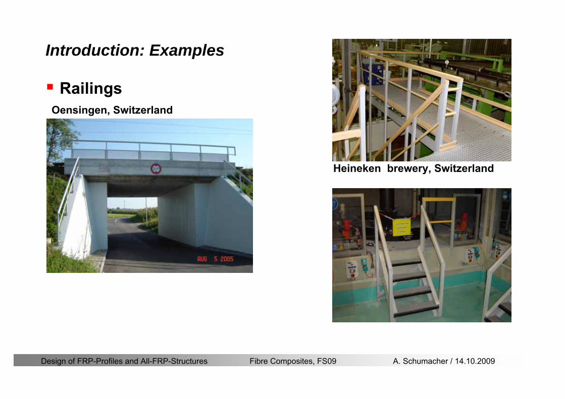
Design of FRP-Profiles and All-FRP-Structures Fibre Composites FS09 A Schumacher 14102009
Introduction Examples
RailingsOensingen Switzerland
Heineken brewery Switzerland
Design of FRP-Profiles and All-FRP-Structures Fibre Composites FS09 A Schumacher 14102009
Introduction Application
Applications where GFRP structures are competitive
Significant corrosion and chemical resistance is required(Food and chemical processing plants cooling towers offshore platforms hellip)
Electromagnetic transparency or electrical insulation is required
Light-weight is cost essential(fast deployment hellip)
Prestige and demonstration objects (eg Novartis Campus Entrance Building)
Photo Prof Th Keller EPFL
Design of FRP-Profiles and All-FRP-Structures Fibre Composites FS09 A Schumacher 14102009
Material
Design of FRP-Profiles and All-FRP-Structures Fibre Composites FS09 A Schumacher 14102009
Only pultruded GFRP profiles will be considered in this lecture
Production of profiles with constant cross-section along the length
High quality
Continuous longitudinal fiber bundles and filament mats
Pultrusion line
Material Pultrusion process
Design of FRP-Profiles and All-FRP-Structures Fibre Composites FS09 A Schumacher 14102009
Material Components
Pultruded profiles contain three primary componentsreinforcement
Matrix
Supplementaryconstituents
polyesterepoxyphenol
polymerisation agentsfillersadditives
Design of FRP-Profiles and All-FRP-Structures Fibre Composites FS09 A Schumacher 14102009
Material Shapes of pultruded profiles
Available Profiles on Stock
Length up to 12 m
Special cross-sections can be designed and ordered(several kilometres are necessary rarr special tools have to be designed)
Design of FRP-Profiles and All-FRP-Structures Fibre Composites FS09 A Schumacher 14102009
Material Durability
Various environmental and load conditions that affect durability of (G)FRPs in terms of strength stiffness fibermatrix interface integrity cracking
watersea waterchemical solutionsprolonged freezingthermal cycling (freeze-thaw)elevated temperature exposureUV radiationcreep and relaxationfatiguefirehellip
Design of FRP-Profiles and All-FRP-Structures Fibre Composites FS09 A Schumacher 14102009
Material Durability
Environmental reduction factor for different FRP systems and exposure conditions
070Aramidepoxy
050Glassepoxy(chemical plants)
085CarbonepoxyAgressive environ
075Aramidepoxyparking garages)
065Glassepoxy(bridges piers
085CarbonepoxyExterior exposure
085Aramidepoxy
075Glassepoxy
095CarbonepoxyInterior exposure
Environ reductionFiber resin typeExposure condition
Design of FRP-Profiles and All-FRP-Structures Fibre Composites FS09 A Schumacher 14102009
Material Durability
GFRP is more susceptible to degradation than CFRP by the following effects
alkaline effects (caution when GFRP in contact with concrete)acid effectssalt effectsfatigueUV radiation
Fire protection is a major (unsolved) issue for (G)FRP structural elements and components
Smoke generation and toxicity must be consideredStrength of GFRP is affected by fatigue loading(more than CFRP)
Design of FRP-Profiles and All-FRP-Structures Fibre Composites FS09 A Schumacher 14102009
Material Manufacturers
GFRP profiles available on stock
In Europe two companies pultrude FRP-Profiles
Fiberline Composites Denmarkwwwfiberlinecom
Fiberline Design Manual (wwwfiberlinedk)rarr helpful tool to design structures
(material properties geometries connections hellip)
Top Glass Italywwwtopglassit
Design of FRP-Profiles and All-FRP-Structures Fibre Composites FS09 A Schumacher 14102009
Material Manufacturers
GFRP profiles available on stock
In North America
Strongwell USAwwwstrongwellcom
Creative Pultrusions USAwwwcreativepultrusionscom
Bedford Reinforced Plastics USAwwwbedfordplasticscom
Design of FRP-Profiles and All-FRP-Structures Fibre Composites FS09 A Schumacher 14102009
Design Concept
Design of FRP-Profiles and All-FRP-Structures Fibre Composites FS09 A Schumacher 14102009
Design Concept Basic Assumptions
Definitions and directions
Design of FRP-Profiles and All-FRP-Structures Fibre Composites FS09 A Schumacher 14102009
Design Concept
Codes
Every manufacturer has its own profile design rarr No European Design Code is available (only EN13706 about testing and notation)
There exists European guidelines EUROCOMP 1996 Design CodeEUROCOMP 1996 Handbook
Fiberline Design Manual is based on Eurocomp 1996
Design concept (according to Eurocodes and Swisscodes)
Partial safety factors
Measured material parameters
Rules for bolted connections
Design of FRP-Profiles and All-FRP-Structures Fibre Composites FS09 A Schumacher 14102009
Design Concept
Concept of Limit State Design (According to Euro Codes and Swiss Codes)
Ultimate limit stress
Ed le Rd
Ed hellip Calculated stress (including load factors) hellip SIA260 261
Rd hellip Rated value of the resistance capability
where
Rk hellip the calculated resistance capability
kd mγ=
RR
Design of FRP-Profiles and All-FRP-Structures Fibre Composites FS09 A Schumacher 14102009
101020Production process
Operating temperature
111116Degree of postcuring
115115225Derivation of mat properties
FiberlineMinMaxDescriptionCoefficient
Design Concept
Reduction coefficient m m1 m2 m3 m4γ γ γ γ γ= sdot sdot sdot
m1γ
m2γ
m3γ
m4γ
mγ mγ
31312580
2510-20 +60
Long-term loadShort-term load
Operatingtemperature degC m4γ
Design of FRP-Profiles and All-FRP-Structures Fibre Composites FS09 A Schumacher 14102009
Design Concept
Serviceability limit states
Ed le Cd
Ed hellip the crucial action effect due to the load cases considered inthe investigated dimensioning situation Typically maximaldeflection response of the structure
Cd hellip corresponding serviceability limit SIA 261
Design of FRP-Profiles and All-FRP-Structures Fibre Composites FS09 A Schumacher 14102009
Design Concept Basic Assumptions
Material Properties stength values (Fiberline Profiles)
Design of FRP-Profiles and All-FRP-Structures Fibre Composites FS09 A Schumacher 14102009
Design Concept Basic Assumptions
Material Properties stiffness values (Fiberline Profiles)
Design of FRP-Profiles and All-FRP-Structures Fibre Composites FS09 A Schumacher 14102009
Design Concept Basic Assumptions
Typical data sheet of a profile (Fiberline I-Profile)
Design of FRP-Profiles and All-FRP-Structures Fibre Composites FS09 A Schumacher 14102009
Bending Beam
Design of FRP-Profiles and All-FRP-Structures Fibre Composites FS09 A Schumacher 14102009
Bending Beam Design of hellip
Calculate bending moments Md and shear forces Qd acting on the profile using the partial coefficient (SIA 260 261)
Ultimate limit state
Bending
Shear
Ak hellip relevant shear area
d max d max 0max
M MW Wy z b
mzy
fσ γ
⎛ ⎞⎜ ⎟⎜ ⎟⎜ ⎟⎜ ⎟⎝ ⎠
deg= + le
d maxmax
kyAy
m
Q fττ γ= le
Design of FRP-Profiles and All-FRP-Structures Fibre Composites FS09 A Schumacher 14102009
Bending Beam Design of hellip
Serviceability limit state
Deflection limit
hellip typically selected between 200 and 400given by SIA 261 or the building owner
hellip calculated including shear deformations
Vibrations
Light-weighted and lsquosoftrsquo structures are susceptible to vibrations (traffic wind the movement of people hellip)
max 1wL αlt
α
maxw
Design of FRP-Profiles and All-FRP-Structures Fibre Composites FS09 A Schumacher 14102009
Bending Beam Timoshenko Theory
Pultruded profiles have a low shear modulus rarr shear deformation must be taken into account
Several bending theories have been published for beams
Euler-Bernoulli theory (1702)
Timoshenko theory (1968)
Higher order beam theory
A simply supported beam with a symmetric cross-section is discussed
Design of FRP-Profiles and All-FRP-Structures Fibre Composites FS09 A Schumacher 14102009
Bending Beam Timoshenko Theory
Cross-sections planeand perpendicular
1 degree of freedom
w
Cross-sections plane butNOT perpendicular
2 degrees of freedom
w and ψ
Cross-sections do NOTremain plane
3+ degrees of freedom
w ψ and hellip
Design of FRP-Profiles and All-FRP-Structures Fibre Composites FS09 A Schumacher 14102009
Bending Beam Euler vs Timoshenko Theory
Kinematic relationships
( )( )
( )
2 0
x x
y
xx xx
yxxy
u y w xu w x
u y w xxuu
y x
ε
ε
=minus sdot=
part= =minus sdotpartpartpart= + =
part part
( )( )
( )
2 ( ) ( )
x
y
xx x
yxxy x
u y xu w x
u y xxuu x w xy x
ψ
ε ψ
ε ψ
=minus sdot=
part= =minus sdotpartpartpart= + =minus +
part part
Hookrsquos law
0degE and G 2x x xy xyσ ε τ ε= sdot = sdot
z0deg E Iz x xxQS
M y dydz wσ= minus sdot sdot = sdot sdotintint
( )
z0deg E I
z x xQS
y xQS
M y dydz
Q dydz w GA
σ ψ
κ τ ψ κ
= minus sdot sdot = sdot
= sdot = minus sdot sdot
intint
intint
Design of FRP-Profiles and All-FRP-Structures Fibre Composites FS09 A Schumacher 14102009
Bending Beam Euler vs Timoshenko Theory
Equilibrium
Solution for the simply supported beam (distributed load)
In a first approximation the deflections are calculated by direct integration of
z0deg
( ) E IxxM xw = sdot
( )( )z0deg
( ) E I 0x
x
xx x
xx x
q x w GAw GA
QM Q
ψ κψ ψ κ
minus minus sdot sdot
sdot + minus sdot sdot
=minus =
= =minus
Equilibrium on an infinitesimal beam element
Coupled second order differential equation
21 1( ) (0) 0 and ( ) 02 2
M x qLx qx w w L= minus = =
( )3 2 3
0deg z
( ) 224 E Iqxw x L Lx x= sdot minus +sdot sdot
2
0deg z
1 1 1E I 2 2xxw qLx qx⎛ ⎞= minus⎜ ⎟sdot ⎝ ⎠
(0) 0 and ( ) 0(0) 0 (0) 0 and ( ) 0 ( ) 0 x x
w w LM M L Lψ ψ
= == rarr = = rarr =
Functions4 3 2
1 2 3 4 53 2
1 2 3 4
( )
( )
w x A x A x A x A x A
x B x B x B x Bψ
= + + + +
= + + +
Design of FRP-Profiles and All-FRP-Structures Fibre Composites FS09 A Schumacher 14102009
Put in and solve for the coefficients rarr
Bending Beam Euler vs Timoshenko Theory
Use the boundary conditions and the second differential eq to calculate A1 ndash A5
( )0deg z E I 0xx xw GAψ ψ κsdot + minus sdot sdot =
1 01 1 3 3
2 02 2 4 4
24 E I4 2GA
6 E I3 GA
z
z
AB A B A
AB A B A
κ
κ
deg
deg
sdot= minus = minus minus
sdotsdot
= minus = minus minussdot
( ) ( )( )2 2
0
( )2 GA 24 E Iz
qx L x L Lx xqx L xw x
κ deg
minus + minusminus= +
sdot sdot sdot
Deflection at midspan
4
0
52 384 E Iz
qLLw⎛ ⎞⎜ ⎟⎝ ⎠
deg
sdot= sdot4 2
0
52 384 E I 8 GAz
qL q LLw κ⎛ ⎞ +⎜ ⎟⎝ ⎠
deg
sdot sdot= sdot sdot sdot
Design of FRP-Profiles and All-FRP-Structures Fibre Composites FS09 A Schumacher 14102009
General expression for the total beam deflection as a sum of the deflection due to bending and shear
GAxf
IExfxwz sdot+=
deg κ)()()( 2
0
1
Cantilever beam
Simply supported
Concentrated load (P)
Uniformly distr load (q)
Concentrated load (P)
Uniformly distr load (q)
Beam )( max1 wf
3845 4qLsdot
48
3PL
8
4qL
3
3PL
)( max1 wf
8
2qL
4PL
2
2qL
PL
)( maxwx
2L
2L
L
L
Bending Beam Euler vs Timoshenko Theory
Design of FRP-Profiles and All-FRP-Structures Fibre Composites FS09 A Schumacher 14102009
Bending Beam Euler vs Timoshenko Theory
Example influence of the shear deformation
Profile 300 x 150 mm I-beam
Load uniformly distributed
General rule of thumbfor GFRP beams withspandepth gt 25 sheardeformation can beignored
Design of FRP-Profiles and All-FRP-Structures Fibre Composites FS09 A Schumacher 14102009
Bending Beam Example
Choose an appropriate Profile for the following specifications
1 Deflections and loading
=
=
==
1300 rarr wmax=001 mwmaxL
10 kNmqdser
13 kNmqduls
30 mL
max
4 2
0
5384 E I 8 GA
d ser d serz
q L q Lw κ+
deg
sdot sdot= sdot sdot sdot
2
maxz8 2 I
d ulsq L hσ sdot= sdot
maxky
12 Ad ulsq L
τ sdot=
Design of FRP-Profiles and All-FRP-Structures Fibre Composites FS09 A Schumacher 14102009
Bending Beam Example
2 Find a profile with sufficient bending stiffness
Shear deformations are neglected in a first step
rarr from specification table choose I 240x120x12 rarr
3 Check the bending and shear stresses
6 24
0 max
1054 10 Nm5
E I 384d ser
zq Lwdeg = sdot
sdotsdotge
6 20 1369 10 NmE Izdeg = sdot
2
maxz
358 MPa8 2 Id ulsq L hσ sdot= =sdot
max
ky
1 71 MPa2 Ad ulsq L
τ sdot= =
0 185 MPab df degle =
20 MPadfτle =
Design of FRP-Profiles and All-FRP-Structures Fibre Composites FS09 A Schumacher 14102009
Bending Beam Example
m10398384
5 32
0
4
maxminus
deg
sdot=sdotsdotsdot
+sdot
sdot=
GALq
IELq
w serd
z
serd
κ
4 Check deflection (including shear deformation)
5 Remarks
The design of GFRP-profiles is mostly driven by serviceability criteria
Start the design iteration procedure using the maximal deflection criterion
max 001 mwle =
m10198384
5 32
0
4
maxminus
deg
sdot=sdot
sdot+
sdotsdot
=web
serd
z
serd
GALq
IELq
w
(77 mm) (16 mm)
Design of FRP-Profiles and All-FRP-Structures Fibre Composites FS09 A Schumacher 14102009
Bending Beam Stability problems
Lateral-torsional bucklingFlange (compressive) displace laterally to the transverse load direction
Torsional stiffness is too low (especially for open section profiles)
Theoretical calculations or design measuresrarr see eg LP Kollaacuter 2003
Mechanics of composite structuresExample
Compressive flanges are kept in place by connection to the bridge deck
Design of FRP-Profiles and All-FRP-Structures Fibre Composites FS09 A Schumacher 14102009
Bending Beam Stability problems
Flange (compressive) displaces in the direction of the transverse load
Low bending stiffness perpendicular to the pultrusion direction
Weak fiber mats
Local buckling of walls due to in-plane compression
Local buckling of walls due to in-plane shear
Web crushing and web buckling in transverse direction
Design of FRP-Profiles and All-FRP-Structures Fibre Composites FS09 A Schumacher 14102009
Axial Members
Design of FRP-Profiles and All-FRP-Structures Fibre Composites FS09 A Schumacher 14102009
Axial Members Tension
Ultimate limit state under axial tension Nd
Serviceability limit state
Remark The critical aspect of axial members in tension are neither the serviceability nor the ultimate limit state Critical is the load transfer to the GFRP profile
0NdA
tm
fγ
degle
0deg
N LE Axδ sdot= sdot
Design of FRP-Profiles and All-FRP-Structures Fibre Composites FS09 A Schumacher 14102009
Axial Members Compression
Ultimate limit state under axial compression Nd
hellip maximal compressive load
hellip Euler load
hellip Buckling length for columns
hellip coefficient for Youngrsquos modulus = 13
cc
Euler
FNd F1 N
le+
c0degC
A fF
mγsdot
=
20
Euler 2
Nm E k
E IL
πγ
degsdot sdot=
sdot
kL
m Eγ
Design of FRP-Profiles and All-FRP-Structures Fibre Composites FS09 A Schumacher 14102009
Axial Members Compression
The influence of shear deformation should be considered but in the most cases the influence will be small (less than 5)
Local buckling should be considered for short columns
For more information on the various buckling modes and effects rarr see LP Kollaacuter 2003 Mechanics of composite structures
Global buckling Local buckling
Design of FRP-Profiles and All-FRP-Structures Fibre Composites FS09 A Schumacher 14102009
Connections
Design of FRP-Profiles and All-FRP-Structures Fibre Composites FS09 A Schumacher 14102009
Connections Introduction
Design of FRP-Profiles and All-FRP-Structures Fibre Composites FS09 A Schumacher 14102009
Connections Introduction
(from Eurocomp Design Code 1996)
Design of FRP-Profiles and All-FRP-Structures Fibre Composites FS09 A Schumacher 14102009
Connections Bolted joints
Bolts = Stress concentration in the profile and the bolt
It is necessary to ensure that the bolts and the profilecan withstand this concentrated local stress compression
It is necessary to ensure that the region surroundinga group of bolts will not be torn out of the profile
Basic failure modesin bolted shearconnections
bolt shear failure
Design of FRP-Profiles and All-FRP-Structures Fibre Composites FS09 A Schumacher 14102009
Connections Bolted joints
The design procedure is comparable to the one for steel connections but since there exist no standard GFRP material rarr each manufacturer has its own design rules for bolted joints
IMPORTANT REMARKS
The direction of pultrusion and the direction of the force is RELEVANT(anisotropic material)
Use stainless or galvanised steel
Do not cut threads in the composite material
Use screws with shafts
Design of FRP-Profiles and All-FRP-Structures Fibre Composites FS09 A Schumacher 14102009
Calculation of load bearing capacity of bolts
Shear in longitudinal direction (0deg)
Shear in transverse direction (90deg)
Tensile force
Minimum distances
Connections Bolted joints (Fiberline recommendations)
Design of FRP-Profiles and All-FRP-Structures Fibre Composites FS09 A Schumacher 14102009
Joint capacity tables available for shear and tension
m
150 MPa( 13)B d
d tP γsdot sdot=
=
Shear in longitudinal direction 0deg
m
70 MPa( 13)B d
d tP γsdot sdot=
=
Shear in transverse direction 90deg
Connections Bolted joints (Fiberline recommendations)
Design of FRP-Profiles and All-FRP-Structures Fibre Composites FS09 A Schumacher 14102009
Bolted connection in shear eg shear in longitudinal direction
Connections Bolted joints (Fiberline recommendations)
γmPBolt le dt720 MPaγmPBolt le dt240 MPa
γmPBolt le dt240 MPa γmPBolt le dt240 MPaγmPBolt le dt150 MPa
Design of FRP-Profiles and All-FRP-Structures Fibre Composites FS09 A Schumacher 14102009
Bolted connections in tension
Static conditions
Bolt Tearing of bolt in threaded cross-section
Laminate Shear fracture at rim of washer
Geometry and strength
Diameter of washer2d
Tensile strength of bolt hellipfyk
Shear strength of laminatehellipfτ
Thickness of laminatet
Stress area of the boltAs
Diameter of the boltd
s ykd m
A fP γ
sdotle
2d m
d t fP τπγ
sdot sdot sdot sdotle
Connections Bolted joints (Fiberline recommendations)
Design of FRP-Profiles and All-FRP-Structures Fibre Composites FS09 A Schumacher 14102009
Connections Bonded joints
Using an adhesive agent for joining profiles can have advantages
Easy to use easy to make aesthetic joints
Typically more rigid than bolted joints
Glued joints subjected to dynamic loads are good
But be careful hellipAdhesive agents have properties that depend on time temperature humidity hellip
Failure in glued joints takes place suddenly (brittle behaviour)
The load-bearing capacity is not proportional to the area which is glued
The design of bonded joints may be based onAnalytical models for plate-to-plate connections (see Eurocomp 1996 Design Code)
Design guidelines supplemented by testing
Finite element analysis
Design of FRP-Profiles and All-FRP-Structures Fibre Composites FS09 A Schumacher 14102009
Connections Bonded joints
A bonded joint has the following three primary failure modes
adhesive failure
cohesive failure of adhesive
cohesive failure of adherend
The design of any bonded joint shall satisfy the following conditions
allowable shear stress in the adhesive is not exceeded
allowable tensile (peel) stress in the adhesive is not exceeded
allowable through-thickness tensile stress of the adhesive is not exceeded
allowable in-plane shear stress of the adherend should not be exceeded
The calculation of the stresses has to be done very carefully Often calculations are supplemented by testing
Design of FRP-Profiles and All-FRP-Structures Fibre Composites FS09 A Schumacher 14102009
Connections Bonded joints
Different types of bonded joint configurations
Research on bonded joints for structuralapplications
Design of FRP-Profiles and All-FRP-Structures Fibre Composites FS09 A Schumacher 14102009
Connections Other joints
Brackets for assembly (Fiberline)
Custom pultruded connections
Design of FRP-Profiles and All-FRP-Structures Fibre Composites FS09 A Schumacher 14102009
GFRP Some final remarks
Perpendicular to the direction of pultrusion the material is WEAK and SOFTrarr avoid such loadings if possible
In order to use pultruded GFRP-profiles economically the design must be done in a clever way eg for bridges the railings should be used as part of the load-bearing structure
GFRP structures are very light rarr vibration problems may occur
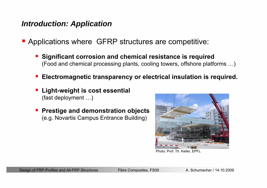
Design of FRP-Profiles and All-FRP-Structures Fibre Composites FS09 A Schumacher 14102009
Material
Design of FRP-Profiles and All-FRP-Structures Fibre Composites FS09 A Schumacher 14102009
Only pultruded GFRP profiles will be considered in this lecture
Production of profiles with constant cross-section along the length
High quality
Continuous longitudinal fiber bundles and filament mats
Pultrusion line
Material Pultrusion process
Design of FRP-Profiles and All-FRP-Structures Fibre Composites FS09 A Schumacher 14102009
Material Components
Pultruded profiles contain three primary componentsreinforcement
Matrix
Supplementaryconstituents
polyesterepoxyphenol
polymerisation agentsfillersadditives
Design of FRP-Profiles and All-FRP-Structures Fibre Composites FS09 A Schumacher 14102009
Material Shapes of pultruded profiles
Available Profiles on Stock
Length up to 12 m
Special cross-sections can be designed and ordered(several kilometres are necessary rarr special tools have to be designed)
Design of FRP-Profiles and All-FRP-Structures Fibre Composites FS09 A Schumacher 14102009
Material Durability
Various environmental and load conditions that affect durability of (G)FRPs in terms of strength stiffness fibermatrix interface integrity cracking
watersea waterchemical solutionsprolonged freezingthermal cycling (freeze-thaw)elevated temperature exposureUV radiationcreep and relaxationfatiguefirehellip
Design of FRP-Profiles and All-FRP-Structures Fibre Composites FS09 A Schumacher 14102009
Material Durability
Environmental reduction factor for different FRP systems and exposure conditions
070Aramidepoxy
050Glassepoxy(chemical plants)
085CarbonepoxyAgressive environ
075Aramidepoxyparking garages)
065Glassepoxy(bridges piers
085CarbonepoxyExterior exposure
085Aramidepoxy
075Glassepoxy
095CarbonepoxyInterior exposure
Environ reductionFiber resin typeExposure condition
Design of FRP-Profiles and All-FRP-Structures Fibre Composites FS09 A Schumacher 14102009
Material Durability
GFRP is more susceptible to degradation than CFRP by the following effects
alkaline effects (caution when GFRP in contact with concrete)acid effectssalt effectsfatigueUV radiation
Fire protection is a major (unsolved) issue for (G)FRP structural elements and components
Smoke generation and toxicity must be consideredStrength of GFRP is affected by fatigue loading(more than CFRP)
Design of FRP-Profiles and All-FRP-Structures Fibre Composites FS09 A Schumacher 14102009
Material Manufacturers
GFRP profiles available on stock
In Europe two companies pultrude FRP-Profiles
Fiberline Composites Denmarkwwwfiberlinecom
Fiberline Design Manual (wwwfiberlinedk)rarr helpful tool to design structures
(material properties geometries connections hellip)
Top Glass Italywwwtopglassit
Design of FRP-Profiles and All-FRP-Structures Fibre Composites FS09 A Schumacher 14102009
Material Manufacturers
GFRP profiles available on stock
In North America
Strongwell USAwwwstrongwellcom
Creative Pultrusions USAwwwcreativepultrusionscom
Bedford Reinforced Plastics USAwwwbedfordplasticscom
Design of FRP-Profiles and All-FRP-Structures Fibre Composites FS09 A Schumacher 14102009
Design Concept
Design of FRP-Profiles and All-FRP-Structures Fibre Composites FS09 A Schumacher 14102009
Design Concept Basic Assumptions
Definitions and directions
Design of FRP-Profiles and All-FRP-Structures Fibre Composites FS09 A Schumacher 14102009
Design Concept
Codes
Every manufacturer has its own profile design rarr No European Design Code is available (only EN13706 about testing and notation)
There exists European guidelines EUROCOMP 1996 Design CodeEUROCOMP 1996 Handbook
Fiberline Design Manual is based on Eurocomp 1996
Design concept (according to Eurocodes and Swisscodes)
Partial safety factors
Measured material parameters
Rules for bolted connections
Design of FRP-Profiles and All-FRP-Structures Fibre Composites FS09 A Schumacher 14102009
Design Concept
Concept of Limit State Design (According to Euro Codes and Swiss Codes)
Ultimate limit stress
Ed le Rd
Ed hellip Calculated stress (including load factors) hellip SIA260 261
Rd hellip Rated value of the resistance capability
where
Rk hellip the calculated resistance capability
kd mγ=
RR
Design of FRP-Profiles and All-FRP-Structures Fibre Composites FS09 A Schumacher 14102009
101020Production process
Operating temperature
111116Degree of postcuring
115115225Derivation of mat properties
FiberlineMinMaxDescriptionCoefficient
Design Concept
Reduction coefficient m m1 m2 m3 m4γ γ γ γ γ= sdot sdot sdot
m1γ
m2γ
m3γ
m4γ
mγ mγ
31312580
2510-20 +60
Long-term loadShort-term load
Operatingtemperature degC m4γ
Design of FRP-Profiles and All-FRP-Structures Fibre Composites FS09 A Schumacher 14102009
Design Concept
Serviceability limit states
Ed le Cd
Ed hellip the crucial action effect due to the load cases considered inthe investigated dimensioning situation Typically maximaldeflection response of the structure
Cd hellip corresponding serviceability limit SIA 261
Design of FRP-Profiles and All-FRP-Structures Fibre Composites FS09 A Schumacher 14102009
Design Concept Basic Assumptions
Material Properties stength values (Fiberline Profiles)
Design of FRP-Profiles and All-FRP-Structures Fibre Composites FS09 A Schumacher 14102009
Design Concept Basic Assumptions
Material Properties stiffness values (Fiberline Profiles)
Design of FRP-Profiles and All-FRP-Structures Fibre Composites FS09 A Schumacher 14102009
Design Concept Basic Assumptions
Typical data sheet of a profile (Fiberline I-Profile)
Design of FRP-Profiles and All-FRP-Structures Fibre Composites FS09 A Schumacher 14102009
Bending Beam
Design of FRP-Profiles and All-FRP-Structures Fibre Composites FS09 A Schumacher 14102009
Bending Beam Design of hellip
Calculate bending moments Md and shear forces Qd acting on the profile using the partial coefficient (SIA 260 261)
Ultimate limit state
Bending
Shear
Ak hellip relevant shear area
d max d max 0max
M MW Wy z b
mzy
fσ γ
⎛ ⎞⎜ ⎟⎜ ⎟⎜ ⎟⎜ ⎟⎝ ⎠
deg= + le
d maxmax
kyAy
m
Q fττ γ= le
Design of FRP-Profiles and All-FRP-Structures Fibre Composites FS09 A Schumacher 14102009
Bending Beam Design of hellip
Serviceability limit state
Deflection limit
hellip typically selected between 200 and 400given by SIA 261 or the building owner
hellip calculated including shear deformations
Vibrations
Light-weighted and lsquosoftrsquo structures are susceptible to vibrations (traffic wind the movement of people hellip)
max 1wL αlt
α
maxw
Design of FRP-Profiles and All-FRP-Structures Fibre Composites FS09 A Schumacher 14102009
Bending Beam Timoshenko Theory
Pultruded profiles have a low shear modulus rarr shear deformation must be taken into account
Several bending theories have been published for beams
Euler-Bernoulli theory (1702)
Timoshenko theory (1968)
Higher order beam theory
A simply supported beam with a symmetric cross-section is discussed
Design of FRP-Profiles and All-FRP-Structures Fibre Composites FS09 A Schumacher 14102009
Bending Beam Timoshenko Theory
Cross-sections planeand perpendicular
1 degree of freedom
w
Cross-sections plane butNOT perpendicular
2 degrees of freedom
w and ψ
Cross-sections do NOTremain plane
3+ degrees of freedom
w ψ and hellip
Design of FRP-Profiles and All-FRP-Structures Fibre Composites FS09 A Schumacher 14102009
Bending Beam Euler vs Timoshenko Theory
Kinematic relationships
( )( )
( )
2 0
x x
y
xx xx
yxxy
u y w xu w x
u y w xxuu
y x
ε
ε
=minus sdot=
part= =minus sdotpartpartpart= + =
part part
( )( )
( )
2 ( ) ( )
x
y
xx x
yxxy x
u y xu w x
u y xxuu x w xy x
ψ
ε ψ
ε ψ
=minus sdot=
part= =minus sdotpartpartpart= + =minus +
part part
Hookrsquos law
0degE and G 2x x xy xyσ ε τ ε= sdot = sdot
z0deg E Iz x xxQS
M y dydz wσ= minus sdot sdot = sdot sdotintint
( )
z0deg E I
z x xQS
y xQS
M y dydz
Q dydz w GA
σ ψ
κ τ ψ κ
= minus sdot sdot = sdot
= sdot = minus sdot sdot
intint
intint
Design of FRP-Profiles and All-FRP-Structures Fibre Composites FS09 A Schumacher 14102009
Bending Beam Euler vs Timoshenko Theory
Equilibrium
Solution for the simply supported beam (distributed load)
In a first approximation the deflections are calculated by direct integration of
z0deg
( ) E IxxM xw = sdot
( )( )z0deg
( ) E I 0x
x
xx x
xx x
q x w GAw GA
QM Q
ψ κψ ψ κ
minus minus sdot sdot
sdot + minus sdot sdot
=minus =
= =minus
Equilibrium on an infinitesimal beam element
Coupled second order differential equation
21 1( ) (0) 0 and ( ) 02 2
M x qLx qx w w L= minus = =
( )3 2 3
0deg z
( ) 224 E Iqxw x L Lx x= sdot minus +sdot sdot
2
0deg z
1 1 1E I 2 2xxw qLx qx⎛ ⎞= minus⎜ ⎟sdot ⎝ ⎠
(0) 0 and ( ) 0(0) 0 (0) 0 and ( ) 0 ( ) 0 x x
w w LM M L Lψ ψ
= == rarr = = rarr =
Functions4 3 2
1 2 3 4 53 2
1 2 3 4
( )
( )
w x A x A x A x A x A
x B x B x B x Bψ
= + + + +
= + + +
Design of FRP-Profiles and All-FRP-Structures Fibre Composites FS09 A Schumacher 14102009
Put in and solve for the coefficients rarr
Bending Beam Euler vs Timoshenko Theory
Use the boundary conditions and the second differential eq to calculate A1 ndash A5
( )0deg z E I 0xx xw GAψ ψ κsdot + minus sdot sdot =
1 01 1 3 3
2 02 2 4 4
24 E I4 2GA
6 E I3 GA
z
z
AB A B A
AB A B A
κ
κ
deg
deg
sdot= minus = minus minus
sdotsdot
= minus = minus minussdot
( ) ( )( )2 2
0
( )2 GA 24 E Iz
qx L x L Lx xqx L xw x
κ deg
minus + minusminus= +
sdot sdot sdot
Deflection at midspan
4
0
52 384 E Iz
qLLw⎛ ⎞⎜ ⎟⎝ ⎠
deg
sdot= sdot4 2
0
52 384 E I 8 GAz
qL q LLw κ⎛ ⎞ +⎜ ⎟⎝ ⎠
deg
sdot sdot= sdot sdot sdot
Design of FRP-Profiles and All-FRP-Structures Fibre Composites FS09 A Schumacher 14102009
General expression for the total beam deflection as a sum of the deflection due to bending and shear
GAxf
IExfxwz sdot+=
deg κ)()()( 2
0
1
Cantilever beam
Simply supported
Concentrated load (P)
Uniformly distr load (q)
Concentrated load (P)
Uniformly distr load (q)
Beam )( max1 wf
3845 4qLsdot
48
3PL
8
4qL
3
3PL
)( max1 wf
8
2qL
4PL
2
2qL
PL
)( maxwx
2L
2L
L
L
Bending Beam Euler vs Timoshenko Theory
Design of FRP-Profiles and All-FRP-Structures Fibre Composites FS09 A Schumacher 14102009
Bending Beam Euler vs Timoshenko Theory
Example influence of the shear deformation
Profile 300 x 150 mm I-beam
Load uniformly distributed
General rule of thumbfor GFRP beams withspandepth gt 25 sheardeformation can beignored
Design of FRP-Profiles and All-FRP-Structures Fibre Composites FS09 A Schumacher 14102009
Bending Beam Example
Choose an appropriate Profile for the following specifications
1 Deflections and loading
=
=
==
1300 rarr wmax=001 mwmaxL
10 kNmqdser
13 kNmqduls
30 mL
max
4 2
0
5384 E I 8 GA
d ser d serz
q L q Lw κ+
deg
sdot sdot= sdot sdot sdot
2
maxz8 2 I
d ulsq L hσ sdot= sdot
maxky
12 Ad ulsq L
τ sdot=
Design of FRP-Profiles and All-FRP-Structures Fibre Composites FS09 A Schumacher 14102009
Bending Beam Example
2 Find a profile with sufficient bending stiffness
Shear deformations are neglected in a first step
rarr from specification table choose I 240x120x12 rarr
3 Check the bending and shear stresses
6 24
0 max
1054 10 Nm5
E I 384d ser
zq Lwdeg = sdot
sdotsdotge
6 20 1369 10 NmE Izdeg = sdot
2
maxz
358 MPa8 2 Id ulsq L hσ sdot= =sdot
max
ky
1 71 MPa2 Ad ulsq L
τ sdot= =
0 185 MPab df degle =
20 MPadfτle =
Design of FRP-Profiles and All-FRP-Structures Fibre Composites FS09 A Schumacher 14102009
Bending Beam Example
m10398384
5 32
0
4
maxminus
deg
sdot=sdotsdotsdot
+sdot
sdot=
GALq
IELq
w serd
z
serd
κ
4 Check deflection (including shear deformation)
5 Remarks
The design of GFRP-profiles is mostly driven by serviceability criteria
Start the design iteration procedure using the maximal deflection criterion
max 001 mwle =
m10198384
5 32
0
4
maxminus
deg
sdot=sdot
sdot+
sdotsdot
=web
serd
z
serd
GALq
IELq
w
(77 mm) (16 mm)
Design of FRP-Profiles and All-FRP-Structures Fibre Composites FS09 A Schumacher 14102009
Bending Beam Stability problems
Lateral-torsional bucklingFlange (compressive) displace laterally to the transverse load direction
Torsional stiffness is too low (especially for open section profiles)
Theoretical calculations or design measuresrarr see eg LP Kollaacuter 2003
Mechanics of composite structuresExample
Compressive flanges are kept in place by connection to the bridge deck
Design of FRP-Profiles and All-FRP-Structures Fibre Composites FS09 A Schumacher 14102009
Bending Beam Stability problems
Flange (compressive) displaces in the direction of the transverse load
Low bending stiffness perpendicular to the pultrusion direction
Weak fiber mats
Local buckling of walls due to in-plane compression
Local buckling of walls due to in-plane shear
Web crushing and web buckling in transverse direction
Design of FRP-Profiles and All-FRP-Structures Fibre Composites FS09 A Schumacher 14102009
Axial Members
Design of FRP-Profiles and All-FRP-Structures Fibre Composites FS09 A Schumacher 14102009
Axial Members Tension
Ultimate limit state under axial tension Nd
Serviceability limit state
Remark The critical aspect of axial members in tension are neither the serviceability nor the ultimate limit state Critical is the load transfer to the GFRP profile
0NdA
tm
fγ
degle
0deg
N LE Axδ sdot= sdot
Design of FRP-Profiles and All-FRP-Structures Fibre Composites FS09 A Schumacher 14102009
Axial Members Compression
Ultimate limit state under axial compression Nd
hellip maximal compressive load
hellip Euler load
hellip Buckling length for columns
hellip coefficient for Youngrsquos modulus = 13
cc
Euler
FNd F1 N
le+
c0degC
A fF
mγsdot
=
20
Euler 2
Nm E k
E IL
πγ
degsdot sdot=
sdot
kL
m Eγ
Design of FRP-Profiles and All-FRP-Structures Fibre Composites FS09 A Schumacher 14102009
Axial Members Compression
The influence of shear deformation should be considered but in the most cases the influence will be small (less than 5)
Local buckling should be considered for short columns
For more information on the various buckling modes and effects rarr see LP Kollaacuter 2003 Mechanics of composite structures
Global buckling Local buckling
Design of FRP-Profiles and All-FRP-Structures Fibre Composites FS09 A Schumacher 14102009
Connections
Design of FRP-Profiles and All-FRP-Structures Fibre Composites FS09 A Schumacher 14102009
Connections Introduction
Design of FRP-Profiles and All-FRP-Structures Fibre Composites FS09 A Schumacher 14102009
Connections Introduction
(from Eurocomp Design Code 1996)
Design of FRP-Profiles and All-FRP-Structures Fibre Composites FS09 A Schumacher 14102009
Connections Bolted joints
Bolts = Stress concentration in the profile and the bolt
It is necessary to ensure that the bolts and the profilecan withstand this concentrated local stress compression
It is necessary to ensure that the region surroundinga group of bolts will not be torn out of the profile
Basic failure modesin bolted shearconnections
bolt shear failure
Design of FRP-Profiles and All-FRP-Structures Fibre Composites FS09 A Schumacher 14102009
Connections Bolted joints
The design procedure is comparable to the one for steel connections but since there exist no standard GFRP material rarr each manufacturer has its own design rules for bolted joints
IMPORTANT REMARKS
The direction of pultrusion and the direction of the force is RELEVANT(anisotropic material)
Use stainless or galvanised steel
Do not cut threads in the composite material
Use screws with shafts
Design of FRP-Profiles and All-FRP-Structures Fibre Composites FS09 A Schumacher 14102009
Calculation of load bearing capacity of bolts
Shear in longitudinal direction (0deg)
Shear in transverse direction (90deg)
Tensile force
Minimum distances
Connections Bolted joints (Fiberline recommendations)
Design of FRP-Profiles and All-FRP-Structures Fibre Composites FS09 A Schumacher 14102009
Joint capacity tables available for shear and tension
m
150 MPa( 13)B d
d tP γsdot sdot=
=
Shear in longitudinal direction 0deg
m
70 MPa( 13)B d
d tP γsdot sdot=
=
Shear in transverse direction 90deg
Connections Bolted joints (Fiberline recommendations)
Design of FRP-Profiles and All-FRP-Structures Fibre Composites FS09 A Schumacher 14102009
Bolted connection in shear eg shear in longitudinal direction
Connections Bolted joints (Fiberline recommendations)
γmPBolt le dt720 MPaγmPBolt le dt240 MPa
γmPBolt le dt240 MPa γmPBolt le dt240 MPaγmPBolt le dt150 MPa
Design of FRP-Profiles and All-FRP-Structures Fibre Composites FS09 A Schumacher 14102009
Bolted connections in tension
Static conditions
Bolt Tearing of bolt in threaded cross-section
Laminate Shear fracture at rim of washer
Geometry and strength
Diameter of washer2d
Tensile strength of bolt hellipfyk
Shear strength of laminatehellipfτ
Thickness of laminatet
Stress area of the boltAs
Diameter of the boltd
s ykd m
A fP γ
sdotle
2d m
d t fP τπγ
sdot sdot sdot sdotle
Connections Bolted joints (Fiberline recommendations)
Design of FRP-Profiles and All-FRP-Structures Fibre Composites FS09 A Schumacher 14102009
Connections Bonded joints
Using an adhesive agent for joining profiles can have advantages
Easy to use easy to make aesthetic joints
Typically more rigid than bolted joints
Glued joints subjected to dynamic loads are good
But be careful hellipAdhesive agents have properties that depend on time temperature humidity hellip
Failure in glued joints takes place suddenly (brittle behaviour)
The load-bearing capacity is not proportional to the area which is glued
The design of bonded joints may be based onAnalytical models for plate-to-plate connections (see Eurocomp 1996 Design Code)
Design guidelines supplemented by testing
Finite element analysis
Design of FRP-Profiles and All-FRP-Structures Fibre Composites FS09 A Schumacher 14102009
Connections Bonded joints
A bonded joint has the following three primary failure modes
adhesive failure
cohesive failure of adhesive
cohesive failure of adherend
The design of any bonded joint shall satisfy the following conditions
allowable shear stress in the adhesive is not exceeded
allowable tensile (peel) stress in the adhesive is not exceeded
allowable through-thickness tensile stress of the adhesive is not exceeded
allowable in-plane shear stress of the adherend should not be exceeded
The calculation of the stresses has to be done very carefully Often calculations are supplemented by testing
Design of FRP-Profiles and All-FRP-Structures Fibre Composites FS09 A Schumacher 14102009
Connections Bonded joints
Different types of bonded joint configurations
Research on bonded joints for structuralapplications
Design of FRP-Profiles and All-FRP-Structures Fibre Composites FS09 A Schumacher 14102009
Connections Other joints
Brackets for assembly (Fiberline)
Custom pultruded connections
Design of FRP-Profiles and All-FRP-Structures Fibre Composites FS09 A Schumacher 14102009
GFRP Some final remarks
Perpendicular to the direction of pultrusion the material is WEAK and SOFTrarr avoid such loadings if possible
In order to use pultruded GFRP-profiles economically the design must be done in a clever way eg for bridges the railings should be used as part of the load-bearing structure
GFRP structures are very light rarr vibration problems may occur
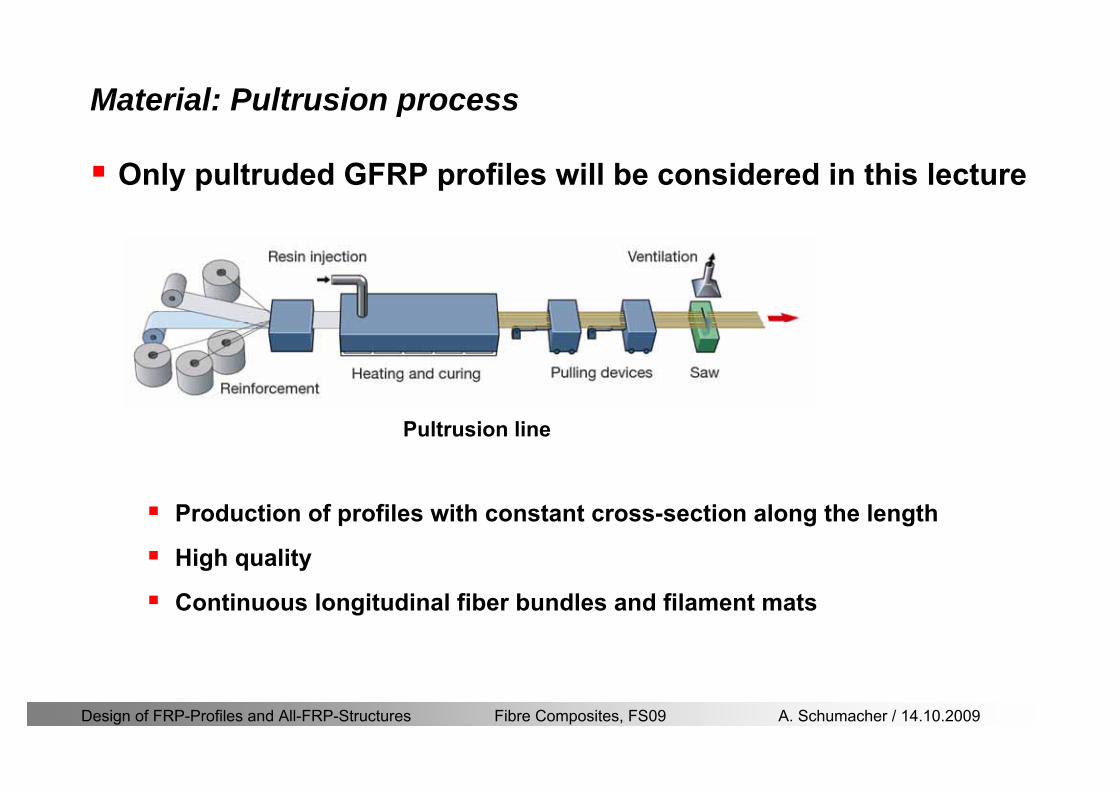
Design of FRP-Profiles and All-FRP-Structures Fibre Composites FS09 A Schumacher 14102009
Only pultruded GFRP profiles will be considered in this lecture
Production of profiles with constant cross-section along the length
High quality
Continuous longitudinal fiber bundles and filament mats
Pultrusion line
Material Pultrusion process
Design of FRP-Profiles and All-FRP-Structures Fibre Composites FS09 A Schumacher 14102009
Material Components
Pultruded profiles contain three primary componentsreinforcement
Matrix
Supplementaryconstituents
polyesterepoxyphenol
polymerisation agentsfillersadditives
Design of FRP-Profiles and All-FRP-Structures Fibre Composites FS09 A Schumacher 14102009
Material Shapes of pultruded profiles
Available Profiles on Stock
Length up to 12 m
Special cross-sections can be designed and ordered(several kilometres are necessary rarr special tools have to be designed)
Design of FRP-Profiles and All-FRP-Structures Fibre Composites FS09 A Schumacher 14102009
Material Durability
Various environmental and load conditions that affect durability of (G)FRPs in terms of strength stiffness fibermatrix interface integrity cracking
watersea waterchemical solutionsprolonged freezingthermal cycling (freeze-thaw)elevated temperature exposureUV radiationcreep and relaxationfatiguefirehellip
Design of FRP-Profiles and All-FRP-Structures Fibre Composites FS09 A Schumacher 14102009
Material Durability
Environmental reduction factor for different FRP systems and exposure conditions
070Aramidepoxy
050Glassepoxy(chemical plants)
085CarbonepoxyAgressive environ
075Aramidepoxyparking garages)
065Glassepoxy(bridges piers
085CarbonepoxyExterior exposure
085Aramidepoxy
075Glassepoxy
095CarbonepoxyInterior exposure
Environ reductionFiber resin typeExposure condition
Design of FRP-Profiles and All-FRP-Structures Fibre Composites FS09 A Schumacher 14102009
Material Durability
GFRP is more susceptible to degradation than CFRP by the following effects
alkaline effects (caution when GFRP in contact with concrete)acid effectssalt effectsfatigueUV radiation
Fire protection is a major (unsolved) issue for (G)FRP structural elements and components
Smoke generation and toxicity must be consideredStrength of GFRP is affected by fatigue loading(more than CFRP)
Design of FRP-Profiles and All-FRP-Structures Fibre Composites FS09 A Schumacher 14102009
Material Manufacturers
GFRP profiles available on stock
In Europe two companies pultrude FRP-Profiles
Fiberline Composites Denmarkwwwfiberlinecom
Fiberline Design Manual (wwwfiberlinedk)rarr helpful tool to design structures
(material properties geometries connections hellip)
Top Glass Italywwwtopglassit
Design of FRP-Profiles and All-FRP-Structures Fibre Composites FS09 A Schumacher 14102009
Material Manufacturers
GFRP profiles available on stock
In North America
Strongwell USAwwwstrongwellcom
Creative Pultrusions USAwwwcreativepultrusionscom
Bedford Reinforced Plastics USAwwwbedfordplasticscom
Design of FRP-Profiles and All-FRP-Structures Fibre Composites FS09 A Schumacher 14102009
Design Concept
Design of FRP-Profiles and All-FRP-Structures Fibre Composites FS09 A Schumacher 14102009
Design Concept Basic Assumptions
Definitions and directions
Design of FRP-Profiles and All-FRP-Structures Fibre Composites FS09 A Schumacher 14102009
Design Concept
Codes
Every manufacturer has its own profile design rarr No European Design Code is available (only EN13706 about testing and notation)
There exists European guidelines EUROCOMP 1996 Design CodeEUROCOMP 1996 Handbook
Fiberline Design Manual is based on Eurocomp 1996
Design concept (according to Eurocodes and Swisscodes)
Partial safety factors
Measured material parameters
Rules for bolted connections
Design of FRP-Profiles and All-FRP-Structures Fibre Composites FS09 A Schumacher 14102009
Design Concept
Concept of Limit State Design (According to Euro Codes and Swiss Codes)
Ultimate limit stress
Ed le Rd
Ed hellip Calculated stress (including load factors) hellip SIA260 261
Rd hellip Rated value of the resistance capability
where
Rk hellip the calculated resistance capability
kd mγ=
RR
Design of FRP-Profiles and All-FRP-Structures Fibre Composites FS09 A Schumacher 14102009
101020Production process
Operating temperature
111116Degree of postcuring
115115225Derivation of mat properties
FiberlineMinMaxDescriptionCoefficient
Design Concept
Reduction coefficient m m1 m2 m3 m4γ γ γ γ γ= sdot sdot sdot
m1γ
m2γ
m3γ
m4γ
mγ mγ
31312580
2510-20 +60
Long-term loadShort-term load
Operatingtemperature degC m4γ
Design of FRP-Profiles and All-FRP-Structures Fibre Composites FS09 A Schumacher 14102009
Design Concept
Serviceability limit states
Ed le Cd
Ed hellip the crucial action effect due to the load cases considered inthe investigated dimensioning situation Typically maximaldeflection response of the structure
Cd hellip corresponding serviceability limit SIA 261
Design of FRP-Profiles and All-FRP-Structures Fibre Composites FS09 A Schumacher 14102009
Design Concept Basic Assumptions
Material Properties stength values (Fiberline Profiles)
Design of FRP-Profiles and All-FRP-Structures Fibre Composites FS09 A Schumacher 14102009
Design Concept Basic Assumptions
Material Properties stiffness values (Fiberline Profiles)
Design of FRP-Profiles and All-FRP-Structures Fibre Composites FS09 A Schumacher 14102009
Design Concept Basic Assumptions
Typical data sheet of a profile (Fiberline I-Profile)
Design of FRP-Profiles and All-FRP-Structures Fibre Composites FS09 A Schumacher 14102009
Bending Beam
Design of FRP-Profiles and All-FRP-Structures Fibre Composites FS09 A Schumacher 14102009
Bending Beam Design of hellip
Calculate bending moments Md and shear forces Qd acting on the profile using the partial coefficient (SIA 260 261)
Ultimate limit state
Bending
Shear
Ak hellip relevant shear area
d max d max 0max
M MW Wy z b
mzy
fσ γ
⎛ ⎞⎜ ⎟⎜ ⎟⎜ ⎟⎜ ⎟⎝ ⎠
deg= + le
d maxmax
kyAy
m
Q fττ γ= le
Design of FRP-Profiles and All-FRP-Structures Fibre Composites FS09 A Schumacher 14102009
Bending Beam Design of hellip
Serviceability limit state
Deflection limit
hellip typically selected between 200 and 400given by SIA 261 or the building owner
hellip calculated including shear deformations
Vibrations
Light-weighted and lsquosoftrsquo structures are susceptible to vibrations (traffic wind the movement of people hellip)
max 1wL αlt
α
maxw
Design of FRP-Profiles and All-FRP-Structures Fibre Composites FS09 A Schumacher 14102009
Bending Beam Timoshenko Theory
Pultruded profiles have a low shear modulus rarr shear deformation must be taken into account
Several bending theories have been published for beams
Euler-Bernoulli theory (1702)
Timoshenko theory (1968)
Higher order beam theory
A simply supported beam with a symmetric cross-section is discussed
Design of FRP-Profiles and All-FRP-Structures Fibre Composites FS09 A Schumacher 14102009
Bending Beam Timoshenko Theory
Cross-sections planeand perpendicular
1 degree of freedom
w
Cross-sections plane butNOT perpendicular
2 degrees of freedom
w and ψ
Cross-sections do NOTremain plane
3+ degrees of freedom
w ψ and hellip
Design of FRP-Profiles and All-FRP-Structures Fibre Composites FS09 A Schumacher 14102009
Bending Beam Euler vs Timoshenko Theory
Kinematic relationships
( )( )
( )
2 0
x x
y
xx xx
yxxy
u y w xu w x
u y w xxuu
y x
ε
ε
=minus sdot=
part= =minus sdotpartpartpart= + =
part part
( )( )
( )
2 ( ) ( )
x
y
xx x
yxxy x
u y xu w x
u y xxuu x w xy x
ψ
ε ψ
ε ψ
=minus sdot=
part= =minus sdotpartpartpart= + =minus +
part part
Hookrsquos law
0degE and G 2x x xy xyσ ε τ ε= sdot = sdot
z0deg E Iz x xxQS
M y dydz wσ= minus sdot sdot = sdot sdotintint
( )
z0deg E I
z x xQS
y xQS
M y dydz
Q dydz w GA
σ ψ
κ τ ψ κ
= minus sdot sdot = sdot
= sdot = minus sdot sdot
intint
intint
Design of FRP-Profiles and All-FRP-Structures Fibre Composites FS09 A Schumacher 14102009
Bending Beam Euler vs Timoshenko Theory
Equilibrium
Solution for the simply supported beam (distributed load)
In a first approximation the deflections are calculated by direct integration of
z0deg
( ) E IxxM xw = sdot
( )( )z0deg
( ) E I 0x
x
xx x
xx x
q x w GAw GA
QM Q
ψ κψ ψ κ
minus minus sdot sdot
sdot + minus sdot sdot
=minus =
= =minus
Equilibrium on an infinitesimal beam element
Coupled second order differential equation
21 1( ) (0) 0 and ( ) 02 2
M x qLx qx w w L= minus = =
( )3 2 3
0deg z
( ) 224 E Iqxw x L Lx x= sdot minus +sdot sdot
2
0deg z
1 1 1E I 2 2xxw qLx qx⎛ ⎞= minus⎜ ⎟sdot ⎝ ⎠
(0) 0 and ( ) 0(0) 0 (0) 0 and ( ) 0 ( ) 0 x x
w w LM M L Lψ ψ
= == rarr = = rarr =
Functions4 3 2
1 2 3 4 53 2
1 2 3 4
( )
( )
w x A x A x A x A x A
x B x B x B x Bψ
= + + + +
= + + +
Design of FRP-Profiles and All-FRP-Structures Fibre Composites FS09 A Schumacher 14102009
Put in and solve for the coefficients rarr
Bending Beam Euler vs Timoshenko Theory
Use the boundary conditions and the second differential eq to calculate A1 ndash A5
( )0deg z E I 0xx xw GAψ ψ κsdot + minus sdot sdot =
1 01 1 3 3
2 02 2 4 4
24 E I4 2GA
6 E I3 GA
z
z
AB A B A
AB A B A
κ
κ
deg
deg
sdot= minus = minus minus
sdotsdot
= minus = minus minussdot
( ) ( )( )2 2
0
( )2 GA 24 E Iz
qx L x L Lx xqx L xw x
κ deg
minus + minusminus= +
sdot sdot sdot
Deflection at midspan
4
0
52 384 E Iz
qLLw⎛ ⎞⎜ ⎟⎝ ⎠
deg
sdot= sdot4 2
0
52 384 E I 8 GAz
qL q LLw κ⎛ ⎞ +⎜ ⎟⎝ ⎠
deg
sdot sdot= sdot sdot sdot
Design of FRP-Profiles and All-FRP-Structures Fibre Composites FS09 A Schumacher 14102009
General expression for the total beam deflection as a sum of the deflection due to bending and shear
GAxf
IExfxwz sdot+=
deg κ)()()( 2
0
1
Cantilever beam
Simply supported
Concentrated load (P)
Uniformly distr load (q)
Concentrated load (P)
Uniformly distr load (q)
Beam )( max1 wf
3845 4qLsdot
48
3PL
8
4qL
3
3PL
)( max1 wf
8
2qL
4PL
2
2qL
PL
)( maxwx
2L
2L
L
L
Bending Beam Euler vs Timoshenko Theory
Design of FRP-Profiles and All-FRP-Structures Fibre Composites FS09 A Schumacher 14102009
Bending Beam Euler vs Timoshenko Theory
Example influence of the shear deformation
Profile 300 x 150 mm I-beam
Load uniformly distributed
General rule of thumbfor GFRP beams withspandepth gt 25 sheardeformation can beignored
Design of FRP-Profiles and All-FRP-Structures Fibre Composites FS09 A Schumacher 14102009
Bending Beam Example
Choose an appropriate Profile for the following specifications
1 Deflections and loading
=
=
==
1300 rarr wmax=001 mwmaxL
10 kNmqdser
13 kNmqduls
30 mL
max
4 2
0
5384 E I 8 GA
d ser d serz
q L q Lw κ+
deg
sdot sdot= sdot sdot sdot
2
maxz8 2 I
d ulsq L hσ sdot= sdot
maxky
12 Ad ulsq L
τ sdot=
Design of FRP-Profiles and All-FRP-Structures Fibre Composites FS09 A Schumacher 14102009
Bending Beam Example
2 Find a profile with sufficient bending stiffness
Shear deformations are neglected in a first step
rarr from specification table choose I 240x120x12 rarr
3 Check the bending and shear stresses
6 24
0 max
1054 10 Nm5
E I 384d ser
zq Lwdeg = sdot
sdotsdotge
6 20 1369 10 NmE Izdeg = sdot
2
maxz
358 MPa8 2 Id ulsq L hσ sdot= =sdot
max
ky
1 71 MPa2 Ad ulsq L
τ sdot= =
0 185 MPab df degle =
20 MPadfτle =
Design of FRP-Profiles and All-FRP-Structures Fibre Composites FS09 A Schumacher 14102009
Bending Beam Example
m10398384
5 32
0
4
maxminus
deg
sdot=sdotsdotsdot
+sdot
sdot=
GALq
IELq
w serd
z
serd
κ
4 Check deflection (including shear deformation)
5 Remarks
The design of GFRP-profiles is mostly driven by serviceability criteria
Start the design iteration procedure using the maximal deflection criterion
max 001 mwle =
m10198384
5 32
0
4
maxminus
deg
sdot=sdot
sdot+
sdotsdot
=web
serd
z
serd
GALq
IELq
w
(77 mm) (16 mm)
Design of FRP-Profiles and All-FRP-Structures Fibre Composites FS09 A Schumacher 14102009
Bending Beam Stability problems
Lateral-torsional bucklingFlange (compressive) displace laterally to the transverse load direction
Torsional stiffness is too low (especially for open section profiles)
Theoretical calculations or design measuresrarr see eg LP Kollaacuter 2003
Mechanics of composite structuresExample
Compressive flanges are kept in place by connection to the bridge deck
Design of FRP-Profiles and All-FRP-Structures Fibre Composites FS09 A Schumacher 14102009
Bending Beam Stability problems
Flange (compressive) displaces in the direction of the transverse load
Low bending stiffness perpendicular to the pultrusion direction
Weak fiber mats
Local buckling of walls due to in-plane compression
Local buckling of walls due to in-plane shear
Web crushing and web buckling in transverse direction
Design of FRP-Profiles and All-FRP-Structures Fibre Composites FS09 A Schumacher 14102009
Axial Members
Design of FRP-Profiles and All-FRP-Structures Fibre Composites FS09 A Schumacher 14102009
Axial Members Tension
Ultimate limit state under axial tension Nd
Serviceability limit state
Remark The critical aspect of axial members in tension are neither the serviceability nor the ultimate limit state Critical is the load transfer to the GFRP profile
0NdA
tm
fγ
degle
0deg
N LE Axδ sdot= sdot
Design of FRP-Profiles and All-FRP-Structures Fibre Composites FS09 A Schumacher 14102009
Axial Members Compression
Ultimate limit state under axial compression Nd
hellip maximal compressive load
hellip Euler load
hellip Buckling length for columns
hellip coefficient for Youngrsquos modulus = 13
cc
Euler
FNd F1 N
le+
c0degC
A fF
mγsdot
=
20
Euler 2
Nm E k
E IL
πγ
degsdot sdot=
sdot
kL
m Eγ
Design of FRP-Profiles and All-FRP-Structures Fibre Composites FS09 A Schumacher 14102009
Axial Members Compression
The influence of shear deformation should be considered but in the most cases the influence will be small (less than 5)
Local buckling should be considered for short columns
For more information on the various buckling modes and effects rarr see LP Kollaacuter 2003 Mechanics of composite structures
Global buckling Local buckling
Design of FRP-Profiles and All-FRP-Structures Fibre Composites FS09 A Schumacher 14102009
Connections
Design of FRP-Profiles and All-FRP-Structures Fibre Composites FS09 A Schumacher 14102009
Connections Introduction
Design of FRP-Profiles and All-FRP-Structures Fibre Composites FS09 A Schumacher 14102009
Connections Introduction
(from Eurocomp Design Code 1996)
Design of FRP-Profiles and All-FRP-Structures Fibre Composites FS09 A Schumacher 14102009
Connections Bolted joints
Bolts = Stress concentration in the profile and the bolt
It is necessary to ensure that the bolts and the profilecan withstand this concentrated local stress compression
It is necessary to ensure that the region surroundinga group of bolts will not be torn out of the profile
Basic failure modesin bolted shearconnections
bolt shear failure
Design of FRP-Profiles and All-FRP-Structures Fibre Composites FS09 A Schumacher 14102009
Connections Bolted joints
The design procedure is comparable to the one for steel connections but since there exist no standard GFRP material rarr each manufacturer has its own design rules for bolted joints
IMPORTANT REMARKS
The direction of pultrusion and the direction of the force is RELEVANT(anisotropic material)
Use stainless or galvanised steel
Do not cut threads in the composite material
Use screws with shafts
Design of FRP-Profiles and All-FRP-Structures Fibre Composites FS09 A Schumacher 14102009
Calculation of load bearing capacity of bolts
Shear in longitudinal direction (0deg)
Shear in transverse direction (90deg)
Tensile force
Minimum distances
Connections Bolted joints (Fiberline recommendations)
Design of FRP-Profiles and All-FRP-Structures Fibre Composites FS09 A Schumacher 14102009
Joint capacity tables available for shear and tension
m
150 MPa( 13)B d
d tP γsdot sdot=
=
Shear in longitudinal direction 0deg
m
70 MPa( 13)B d
d tP γsdot sdot=
=
Shear in transverse direction 90deg
Connections Bolted joints (Fiberline recommendations)
Design of FRP-Profiles and All-FRP-Structures Fibre Composites FS09 A Schumacher 14102009
Bolted connection in shear eg shear in longitudinal direction
Connections Bolted joints (Fiberline recommendations)
γmPBolt le dt720 MPaγmPBolt le dt240 MPa
γmPBolt le dt240 MPa γmPBolt le dt240 MPaγmPBolt le dt150 MPa
Design of FRP-Profiles and All-FRP-Structures Fibre Composites FS09 A Schumacher 14102009
Bolted connections in tension
Static conditions
Bolt Tearing of bolt in threaded cross-section
Laminate Shear fracture at rim of washer
Geometry and strength
Diameter of washer2d
Tensile strength of bolt hellipfyk
Shear strength of laminatehellipfτ
Thickness of laminatet
Stress area of the boltAs
Diameter of the boltd
s ykd m
A fP γ
sdotle
2d m
d t fP τπγ
sdot sdot sdot sdotle
Connections Bolted joints (Fiberline recommendations)
Design of FRP-Profiles and All-FRP-Structures Fibre Composites FS09 A Schumacher 14102009
Connections Bonded joints
Using an adhesive agent for joining profiles can have advantages
Easy to use easy to make aesthetic joints
Typically more rigid than bolted joints
Glued joints subjected to dynamic loads are good
But be careful hellipAdhesive agents have properties that depend on time temperature humidity hellip
Failure in glued joints takes place suddenly (brittle behaviour)
The load-bearing capacity is not proportional to the area which is glued
The design of bonded joints may be based onAnalytical models for plate-to-plate connections (see Eurocomp 1996 Design Code)
Design guidelines supplemented by testing
Finite element analysis
Design of FRP-Profiles and All-FRP-Structures Fibre Composites FS09 A Schumacher 14102009
Connections Bonded joints
A bonded joint has the following three primary failure modes
adhesive failure
cohesive failure of adhesive
cohesive failure of adherend
The design of any bonded joint shall satisfy the following conditions
allowable shear stress in the adhesive is not exceeded
allowable tensile (peel) stress in the adhesive is not exceeded
allowable through-thickness tensile stress of the adhesive is not exceeded
allowable in-plane shear stress of the adherend should not be exceeded
The calculation of the stresses has to be done very carefully Often calculations are supplemented by testing
Design of FRP-Profiles and All-FRP-Structures Fibre Composites FS09 A Schumacher 14102009
Connections Bonded joints
Different types of bonded joint configurations
Research on bonded joints for structuralapplications
Design of FRP-Profiles and All-FRP-Structures Fibre Composites FS09 A Schumacher 14102009
Connections Other joints
Brackets for assembly (Fiberline)
Custom pultruded connections
Design of FRP-Profiles and All-FRP-Structures Fibre Composites FS09 A Schumacher 14102009
GFRP Some final remarks
Perpendicular to the direction of pultrusion the material is WEAK and SOFTrarr avoid such loadings if possible
In order to use pultruded GFRP-profiles economically the design must be done in a clever way eg for bridges the railings should be used as part of the load-bearing structure
GFRP structures are very light rarr vibration problems may occur
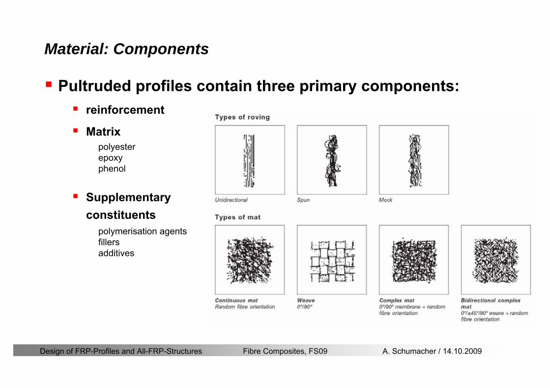
Design of FRP-Profiles and All-FRP-Structures Fibre Composites FS09 A Schumacher 14102009
Material Components
Pultruded profiles contain three primary componentsreinforcement
Matrix
Supplementaryconstituents
polyesterepoxyphenol
polymerisation agentsfillersadditives
Design of FRP-Profiles and All-FRP-Structures Fibre Composites FS09 A Schumacher 14102009
Material Shapes of pultruded profiles
Available Profiles on Stock
Length up to 12 m
Special cross-sections can be designed and ordered(several kilometres are necessary rarr special tools have to be designed)
Design of FRP-Profiles and All-FRP-Structures Fibre Composites FS09 A Schumacher 14102009
Material Durability
Various environmental and load conditions that affect durability of (G)FRPs in terms of strength stiffness fibermatrix interface integrity cracking
watersea waterchemical solutionsprolonged freezingthermal cycling (freeze-thaw)elevated temperature exposureUV radiationcreep and relaxationfatiguefirehellip
Design of FRP-Profiles and All-FRP-Structures Fibre Composites FS09 A Schumacher 14102009
Material Durability
Environmental reduction factor for different FRP systems and exposure conditions
070Aramidepoxy
050Glassepoxy(chemical plants)
085CarbonepoxyAgressive environ
075Aramidepoxyparking garages)
065Glassepoxy(bridges piers
085CarbonepoxyExterior exposure
085Aramidepoxy
075Glassepoxy
095CarbonepoxyInterior exposure
Environ reductionFiber resin typeExposure condition
Design of FRP-Profiles and All-FRP-Structures Fibre Composites FS09 A Schumacher 14102009
Material Durability
GFRP is more susceptible to degradation than CFRP by the following effects
alkaline effects (caution when GFRP in contact with concrete)acid effectssalt effectsfatigueUV radiation
Fire protection is a major (unsolved) issue for (G)FRP structural elements and components
Smoke generation and toxicity must be consideredStrength of GFRP is affected by fatigue loading(more than CFRP)
Design of FRP-Profiles and All-FRP-Structures Fibre Composites FS09 A Schumacher 14102009
Material Manufacturers
GFRP profiles available on stock
In Europe two companies pultrude FRP-Profiles
Fiberline Composites Denmarkwwwfiberlinecom
Fiberline Design Manual (wwwfiberlinedk)rarr helpful tool to design structures
(material properties geometries connections hellip)
Top Glass Italywwwtopglassit
Design of FRP-Profiles and All-FRP-Structures Fibre Composites FS09 A Schumacher 14102009
Material Manufacturers
GFRP profiles available on stock
In North America
Strongwell USAwwwstrongwellcom
Creative Pultrusions USAwwwcreativepultrusionscom
Bedford Reinforced Plastics USAwwwbedfordplasticscom
Design of FRP-Profiles and All-FRP-Structures Fibre Composites FS09 A Schumacher 14102009
Design Concept
Design of FRP-Profiles and All-FRP-Structures Fibre Composites FS09 A Schumacher 14102009
Design Concept Basic Assumptions
Definitions and directions
Design of FRP-Profiles and All-FRP-Structures Fibre Composites FS09 A Schumacher 14102009
Design Concept
Codes
Every manufacturer has its own profile design rarr No European Design Code is available (only EN13706 about testing and notation)
There exists European guidelines EUROCOMP 1996 Design CodeEUROCOMP 1996 Handbook
Fiberline Design Manual is based on Eurocomp 1996
Design concept (according to Eurocodes and Swisscodes)
Partial safety factors
Measured material parameters
Rules for bolted connections
Design of FRP-Profiles and All-FRP-Structures Fibre Composites FS09 A Schumacher 14102009
Design Concept
Concept of Limit State Design (According to Euro Codes and Swiss Codes)
Ultimate limit stress
Ed le Rd
Ed hellip Calculated stress (including load factors) hellip SIA260 261
Rd hellip Rated value of the resistance capability
where
Rk hellip the calculated resistance capability
kd mγ=
RR
Design of FRP-Profiles and All-FRP-Structures Fibre Composites FS09 A Schumacher 14102009
101020Production process
Operating temperature
111116Degree of postcuring
115115225Derivation of mat properties
FiberlineMinMaxDescriptionCoefficient
Design Concept
Reduction coefficient m m1 m2 m3 m4γ γ γ γ γ= sdot sdot sdot
m1γ
m2γ
m3γ
m4γ
mγ mγ
31312580
2510-20 +60
Long-term loadShort-term load
Operatingtemperature degC m4γ
Design of FRP-Profiles and All-FRP-Structures Fibre Composites FS09 A Schumacher 14102009
Design Concept
Serviceability limit states
Ed le Cd
Ed hellip the crucial action effect due to the load cases considered inthe investigated dimensioning situation Typically maximaldeflection response of the structure
Cd hellip corresponding serviceability limit SIA 261
Design of FRP-Profiles and All-FRP-Structures Fibre Composites FS09 A Schumacher 14102009
Design Concept Basic Assumptions
Material Properties stength values (Fiberline Profiles)
Design of FRP-Profiles and All-FRP-Structures Fibre Composites FS09 A Schumacher 14102009
Design Concept Basic Assumptions
Material Properties stiffness values (Fiberline Profiles)
Design of FRP-Profiles and All-FRP-Structures Fibre Composites FS09 A Schumacher 14102009
Design Concept Basic Assumptions
Typical data sheet of a profile (Fiberline I-Profile)
Design of FRP-Profiles and All-FRP-Structures Fibre Composites FS09 A Schumacher 14102009
Bending Beam
Design of FRP-Profiles and All-FRP-Structures Fibre Composites FS09 A Schumacher 14102009
Bending Beam Design of hellip
Calculate bending moments Md and shear forces Qd acting on the profile using the partial coefficient (SIA 260 261)
Ultimate limit state
Bending
Shear
Ak hellip relevant shear area
d max d max 0max
M MW Wy z b
mzy
fσ γ
⎛ ⎞⎜ ⎟⎜ ⎟⎜ ⎟⎜ ⎟⎝ ⎠
deg= + le
d maxmax
kyAy
m
Q fττ γ= le
Design of FRP-Profiles and All-FRP-Structures Fibre Composites FS09 A Schumacher 14102009
Bending Beam Design of hellip
Serviceability limit state
Deflection limit
hellip typically selected between 200 and 400given by SIA 261 or the building owner
hellip calculated including shear deformations
Vibrations
Light-weighted and lsquosoftrsquo structures are susceptible to vibrations (traffic wind the movement of people hellip)
max 1wL αlt
α
maxw
Design of FRP-Profiles and All-FRP-Structures Fibre Composites FS09 A Schumacher 14102009
Bending Beam Timoshenko Theory
Pultruded profiles have a low shear modulus rarr shear deformation must be taken into account
Several bending theories have been published for beams
Euler-Bernoulli theory (1702)
Timoshenko theory (1968)
Higher order beam theory
A simply supported beam with a symmetric cross-section is discussed
Design of FRP-Profiles and All-FRP-Structures Fibre Composites FS09 A Schumacher 14102009
Bending Beam Timoshenko Theory
Cross-sections planeand perpendicular
1 degree of freedom
w
Cross-sections plane butNOT perpendicular
2 degrees of freedom
w and ψ
Cross-sections do NOTremain plane
3+ degrees of freedom
w ψ and hellip
Design of FRP-Profiles and All-FRP-Structures Fibre Composites FS09 A Schumacher 14102009
Bending Beam Euler vs Timoshenko Theory
Kinematic relationships
( )( )
( )
2 0
x x
y
xx xx
yxxy
u y w xu w x
u y w xxuu
y x
ε
ε
=minus sdot=
part= =minus sdotpartpartpart= + =
part part
( )( )
( )
2 ( ) ( )
x
y
xx x
yxxy x
u y xu w x
u y xxuu x w xy x
ψ
ε ψ
ε ψ
=minus sdot=
part= =minus sdotpartpartpart= + =minus +
part part
Hookrsquos law
0degE and G 2x x xy xyσ ε τ ε= sdot = sdot
z0deg E Iz x xxQS
M y dydz wσ= minus sdot sdot = sdot sdotintint
( )
z0deg E I
z x xQS
y xQS
M y dydz
Q dydz w GA
σ ψ
κ τ ψ κ
= minus sdot sdot = sdot
= sdot = minus sdot sdot
intint
intint
Design of FRP-Profiles and All-FRP-Structures Fibre Composites FS09 A Schumacher 14102009
Bending Beam Euler vs Timoshenko Theory
Equilibrium
Solution for the simply supported beam (distributed load)
In a first approximation the deflections are calculated by direct integration of
z0deg
( ) E IxxM xw = sdot
( )( )z0deg
( ) E I 0x
x
xx x
xx x
q x w GAw GA
QM Q
ψ κψ ψ κ
minus minus sdot sdot
sdot + minus sdot sdot
=minus =
= =minus
Equilibrium on an infinitesimal beam element
Coupled second order differential equation
21 1( ) (0) 0 and ( ) 02 2
M x qLx qx w w L= minus = =
( )3 2 3
0deg z
( ) 224 E Iqxw x L Lx x= sdot minus +sdot sdot
2
0deg z
1 1 1E I 2 2xxw qLx qx⎛ ⎞= minus⎜ ⎟sdot ⎝ ⎠
(0) 0 and ( ) 0(0) 0 (0) 0 and ( ) 0 ( ) 0 x x
w w LM M L Lψ ψ
= == rarr = = rarr =
Functions4 3 2
1 2 3 4 53 2
1 2 3 4
( )
( )
w x A x A x A x A x A
x B x B x B x Bψ
= + + + +
= + + +
Design of FRP-Profiles and All-FRP-Structures Fibre Composites FS09 A Schumacher 14102009
Put in and solve for the coefficients rarr
Bending Beam Euler vs Timoshenko Theory
Use the boundary conditions and the second differential eq to calculate A1 ndash A5
( )0deg z E I 0xx xw GAψ ψ κsdot + minus sdot sdot =
1 01 1 3 3
2 02 2 4 4
24 E I4 2GA
6 E I3 GA
z
z
AB A B A
AB A B A
κ
κ
deg
deg
sdot= minus = minus minus
sdotsdot
= minus = minus minussdot
( ) ( )( )2 2
0
( )2 GA 24 E Iz
qx L x L Lx xqx L xw x
κ deg
minus + minusminus= +
sdot sdot sdot
Deflection at midspan
4
0
52 384 E Iz
qLLw⎛ ⎞⎜ ⎟⎝ ⎠
deg
sdot= sdot4 2
0
52 384 E I 8 GAz
qL q LLw κ⎛ ⎞ +⎜ ⎟⎝ ⎠
deg
sdot sdot= sdot sdot sdot
Design of FRP-Profiles and All-FRP-Structures Fibre Composites FS09 A Schumacher 14102009
General expression for the total beam deflection as a sum of the deflection due to bending and shear
GAxf
IExfxwz sdot+=
deg κ)()()( 2
0
1
Cantilever beam
Simply supported
Concentrated load (P)
Uniformly distr load (q)
Concentrated load (P)
Uniformly distr load (q)
Beam )( max1 wf
3845 4qLsdot
48
3PL
8
4qL
3
3PL
)( max1 wf
8
2qL
4PL
2
2qL
PL
)( maxwx
2L
2L
L
L
Bending Beam Euler vs Timoshenko Theory
Design of FRP-Profiles and All-FRP-Structures Fibre Composites FS09 A Schumacher 14102009
Bending Beam Euler vs Timoshenko Theory
Example influence of the shear deformation
Profile 300 x 150 mm I-beam
Load uniformly distributed
General rule of thumbfor GFRP beams withspandepth gt 25 sheardeformation can beignored
Design of FRP-Profiles and All-FRP-Structures Fibre Composites FS09 A Schumacher 14102009
Bending Beam Example
Choose an appropriate Profile for the following specifications
1 Deflections and loading
=
=
==
1300 rarr wmax=001 mwmaxL
10 kNmqdser
13 kNmqduls
30 mL
max
4 2
0
5384 E I 8 GA
d ser d serz
q L q Lw κ+
deg
sdot sdot= sdot sdot sdot
2
maxz8 2 I
d ulsq L hσ sdot= sdot
maxky
12 Ad ulsq L
τ sdot=
Design of FRP-Profiles and All-FRP-Structures Fibre Composites FS09 A Schumacher 14102009
Bending Beam Example
2 Find a profile with sufficient bending stiffness
Shear deformations are neglected in a first step
rarr from specification table choose I 240x120x12 rarr
3 Check the bending and shear stresses
6 24
0 max
1054 10 Nm5
E I 384d ser
zq Lwdeg = sdot
sdotsdotge
6 20 1369 10 NmE Izdeg = sdot
2
maxz
358 MPa8 2 Id ulsq L hσ sdot= =sdot
max
ky
1 71 MPa2 Ad ulsq L
τ sdot= =
0 185 MPab df degle =
20 MPadfτle =
Design of FRP-Profiles and All-FRP-Structures Fibre Composites FS09 A Schumacher 14102009
Bending Beam Example
m10398384
5 32
0
4
maxminus
deg
sdot=sdotsdotsdot
+sdot
sdot=
GALq
IELq
w serd
z
serd
κ
4 Check deflection (including shear deformation)
5 Remarks
The design of GFRP-profiles is mostly driven by serviceability criteria
Start the design iteration procedure using the maximal deflection criterion
max 001 mwle =
m10198384
5 32
0
4
maxminus
deg
sdot=sdot
sdot+
sdotsdot
=web
serd
z
serd
GALq
IELq
w
(77 mm) (16 mm)
Design of FRP-Profiles and All-FRP-Structures Fibre Composites FS09 A Schumacher 14102009
Bending Beam Stability problems
Lateral-torsional bucklingFlange (compressive) displace laterally to the transverse load direction
Torsional stiffness is too low (especially for open section profiles)
Theoretical calculations or design measuresrarr see eg LP Kollaacuter 2003
Mechanics of composite structuresExample
Compressive flanges are kept in place by connection to the bridge deck
Design of FRP-Profiles and All-FRP-Structures Fibre Composites FS09 A Schumacher 14102009
Bending Beam Stability problems
Flange (compressive) displaces in the direction of the transverse load
Low bending stiffness perpendicular to the pultrusion direction
Weak fiber mats
Local buckling of walls due to in-plane compression
Local buckling of walls due to in-plane shear
Web crushing and web buckling in transverse direction
Design of FRP-Profiles and All-FRP-Structures Fibre Composites FS09 A Schumacher 14102009
Axial Members
Design of FRP-Profiles and All-FRP-Structures Fibre Composites FS09 A Schumacher 14102009
Axial Members Tension
Ultimate limit state under axial tension Nd
Serviceability limit state
Remark The critical aspect of axial members in tension are neither the serviceability nor the ultimate limit state Critical is the load transfer to the GFRP profile
0NdA
tm
fγ
degle
0deg
N LE Axδ sdot= sdot
Design of FRP-Profiles and All-FRP-Structures Fibre Composites FS09 A Schumacher 14102009
Axial Members Compression
Ultimate limit state under axial compression Nd
hellip maximal compressive load
hellip Euler load
hellip Buckling length for columns
hellip coefficient for Youngrsquos modulus = 13
cc
Euler
FNd F1 N
le+
c0degC
A fF
mγsdot
=
20
Euler 2
Nm E k
E IL
πγ
degsdot sdot=
sdot
kL
m Eγ
Design of FRP-Profiles and All-FRP-Structures Fibre Composites FS09 A Schumacher 14102009
Axial Members Compression
The influence of shear deformation should be considered but in the most cases the influence will be small (less than 5)
Local buckling should be considered for short columns
For more information on the various buckling modes and effects rarr see LP Kollaacuter 2003 Mechanics of composite structures
Global buckling Local buckling
Design of FRP-Profiles and All-FRP-Structures Fibre Composites FS09 A Schumacher 14102009
Connections
Design of FRP-Profiles and All-FRP-Structures Fibre Composites FS09 A Schumacher 14102009
Connections Introduction
Design of FRP-Profiles and All-FRP-Structures Fibre Composites FS09 A Schumacher 14102009
Connections Introduction
(from Eurocomp Design Code 1996)
Design of FRP-Profiles and All-FRP-Structures Fibre Composites FS09 A Schumacher 14102009
Connections Bolted joints
Bolts = Stress concentration in the profile and the bolt
It is necessary to ensure that the bolts and the profilecan withstand this concentrated local stress compression
It is necessary to ensure that the region surroundinga group of bolts will not be torn out of the profile
Basic failure modesin bolted shearconnections
bolt shear failure
Design of FRP-Profiles and All-FRP-Structures Fibre Composites FS09 A Schumacher 14102009
Connections Bolted joints
The design procedure is comparable to the one for steel connections but since there exist no standard GFRP material rarr each manufacturer has its own design rules for bolted joints
IMPORTANT REMARKS
The direction of pultrusion and the direction of the force is RELEVANT(anisotropic material)
Use stainless or galvanised steel
Do not cut threads in the composite material
Use screws with shafts
Design of FRP-Profiles and All-FRP-Structures Fibre Composites FS09 A Schumacher 14102009
Calculation of load bearing capacity of bolts
Shear in longitudinal direction (0deg)
Shear in transverse direction (90deg)
Tensile force
Minimum distances
Connections Bolted joints (Fiberline recommendations)
Design of FRP-Profiles and All-FRP-Structures Fibre Composites FS09 A Schumacher 14102009
Joint capacity tables available for shear and tension
m
150 MPa( 13)B d
d tP γsdot sdot=
=
Shear in longitudinal direction 0deg
m
70 MPa( 13)B d
d tP γsdot sdot=
=
Shear in transverse direction 90deg
Connections Bolted joints (Fiberline recommendations)
Design of FRP-Profiles and All-FRP-Structures Fibre Composites FS09 A Schumacher 14102009
Bolted connection in shear eg shear in longitudinal direction
Connections Bolted joints (Fiberline recommendations)
γmPBolt le dt720 MPaγmPBolt le dt240 MPa
γmPBolt le dt240 MPa γmPBolt le dt240 MPaγmPBolt le dt150 MPa
Design of FRP-Profiles and All-FRP-Structures Fibre Composites FS09 A Schumacher 14102009
Bolted connections in tension
Static conditions
Bolt Tearing of bolt in threaded cross-section
Laminate Shear fracture at rim of washer
Geometry and strength
Diameter of washer2d
Tensile strength of bolt hellipfyk
Shear strength of laminatehellipfτ
Thickness of laminatet
Stress area of the boltAs
Diameter of the boltd
s ykd m
A fP γ
sdotle
2d m
d t fP τπγ
sdot sdot sdot sdotle
Connections Bolted joints (Fiberline recommendations)
Design of FRP-Profiles and All-FRP-Structures Fibre Composites FS09 A Schumacher 14102009
Connections Bonded joints
Using an adhesive agent for joining profiles can have advantages
Easy to use easy to make aesthetic joints
Typically more rigid than bolted joints
Glued joints subjected to dynamic loads are good
But be careful hellipAdhesive agents have properties that depend on time temperature humidity hellip
Failure in glued joints takes place suddenly (brittle behaviour)
The load-bearing capacity is not proportional to the area which is glued
The design of bonded joints may be based onAnalytical models for plate-to-plate connections (see Eurocomp 1996 Design Code)
Design guidelines supplemented by testing
Finite element analysis
Design of FRP-Profiles and All-FRP-Structures Fibre Composites FS09 A Schumacher 14102009
Connections Bonded joints
A bonded joint has the following three primary failure modes
adhesive failure
cohesive failure of adhesive
cohesive failure of adherend
The design of any bonded joint shall satisfy the following conditions
allowable shear stress in the adhesive is not exceeded
allowable tensile (peel) stress in the adhesive is not exceeded
allowable through-thickness tensile stress of the adhesive is not exceeded
allowable in-plane shear stress of the adherend should not be exceeded
The calculation of the stresses has to be done very carefully Often calculations are supplemented by testing
Design of FRP-Profiles and All-FRP-Structures Fibre Composites FS09 A Schumacher 14102009
Connections Bonded joints
Different types of bonded joint configurations
Research on bonded joints for structuralapplications
Design of FRP-Profiles and All-FRP-Structures Fibre Composites FS09 A Schumacher 14102009
Connections Other joints
Brackets for assembly (Fiberline)
Custom pultruded connections
Design of FRP-Profiles and All-FRP-Structures Fibre Composites FS09 A Schumacher 14102009
GFRP Some final remarks
Perpendicular to the direction of pultrusion the material is WEAK and SOFTrarr avoid such loadings if possible
In order to use pultruded GFRP-profiles economically the design must be done in a clever way eg for bridges the railings should be used as part of the load-bearing structure
GFRP structures are very light rarr vibration problems may occur
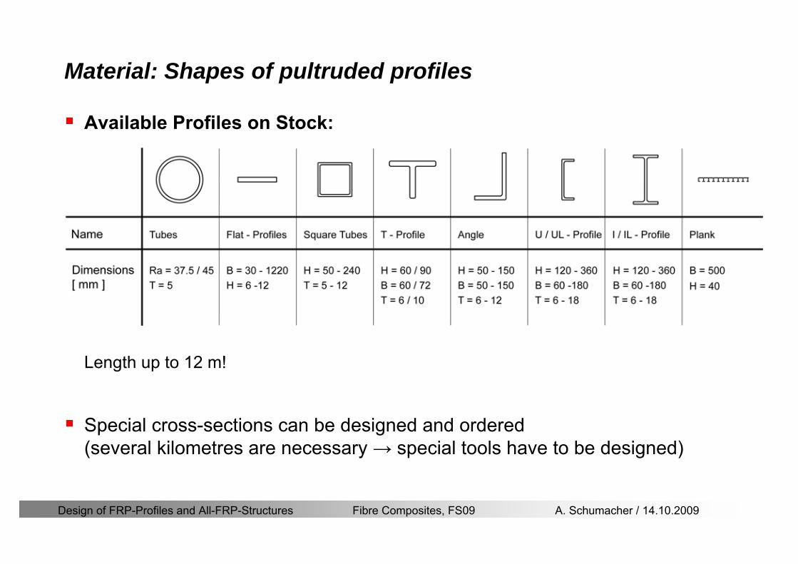
Design of FRP-Profiles and All-FRP-Structures Fibre Composites FS09 A Schumacher 14102009
Material Shapes of pultruded profiles
Available Profiles on Stock
Length up to 12 m
Special cross-sections can be designed and ordered(several kilometres are necessary rarr special tools have to be designed)
Design of FRP-Profiles and All-FRP-Structures Fibre Composites FS09 A Schumacher 14102009
Material Durability
Various environmental and load conditions that affect durability of (G)FRPs in terms of strength stiffness fibermatrix interface integrity cracking
watersea waterchemical solutionsprolonged freezingthermal cycling (freeze-thaw)elevated temperature exposureUV radiationcreep and relaxationfatiguefirehellip
Design of FRP-Profiles and All-FRP-Structures Fibre Composites FS09 A Schumacher 14102009
Material Durability
Environmental reduction factor for different FRP systems and exposure conditions
070Aramidepoxy
050Glassepoxy(chemical plants)
085CarbonepoxyAgressive environ
075Aramidepoxyparking garages)
065Glassepoxy(bridges piers
085CarbonepoxyExterior exposure
085Aramidepoxy
075Glassepoxy
095CarbonepoxyInterior exposure
Environ reductionFiber resin typeExposure condition
Design of FRP-Profiles and All-FRP-Structures Fibre Composites FS09 A Schumacher 14102009
Material Durability
GFRP is more susceptible to degradation than CFRP by the following effects
alkaline effects (caution when GFRP in contact with concrete)acid effectssalt effectsfatigueUV radiation
Fire protection is a major (unsolved) issue for (G)FRP structural elements and components
Smoke generation and toxicity must be consideredStrength of GFRP is affected by fatigue loading(more than CFRP)
Design of FRP-Profiles and All-FRP-Structures Fibre Composites FS09 A Schumacher 14102009
Material Manufacturers
GFRP profiles available on stock
In Europe two companies pultrude FRP-Profiles
Fiberline Composites Denmarkwwwfiberlinecom
Fiberline Design Manual (wwwfiberlinedk)rarr helpful tool to design structures
(material properties geometries connections hellip)
Top Glass Italywwwtopglassit
Design of FRP-Profiles and All-FRP-Structures Fibre Composites FS09 A Schumacher 14102009
Material Manufacturers
GFRP profiles available on stock
In North America
Strongwell USAwwwstrongwellcom
Creative Pultrusions USAwwwcreativepultrusionscom
Bedford Reinforced Plastics USAwwwbedfordplasticscom
Design of FRP-Profiles and All-FRP-Structures Fibre Composites FS09 A Schumacher 14102009
Design Concept
Design of FRP-Profiles and All-FRP-Structures Fibre Composites FS09 A Schumacher 14102009
Design Concept Basic Assumptions
Definitions and directions
Design of FRP-Profiles and All-FRP-Structures Fibre Composites FS09 A Schumacher 14102009
Design Concept
Codes
Every manufacturer has its own profile design rarr No European Design Code is available (only EN13706 about testing and notation)
There exists European guidelines EUROCOMP 1996 Design CodeEUROCOMP 1996 Handbook
Fiberline Design Manual is based on Eurocomp 1996
Design concept (according to Eurocodes and Swisscodes)
Partial safety factors
Measured material parameters
Rules for bolted connections
Design of FRP-Profiles and All-FRP-Structures Fibre Composites FS09 A Schumacher 14102009
Design Concept
Concept of Limit State Design (According to Euro Codes and Swiss Codes)
Ultimate limit stress
Ed le Rd
Ed hellip Calculated stress (including load factors) hellip SIA260 261
Rd hellip Rated value of the resistance capability
where
Rk hellip the calculated resistance capability
kd mγ=
RR
Design of FRP-Profiles and All-FRP-Structures Fibre Composites FS09 A Schumacher 14102009
101020Production process
Operating temperature
111116Degree of postcuring
115115225Derivation of mat properties
FiberlineMinMaxDescriptionCoefficient
Design Concept
Reduction coefficient m m1 m2 m3 m4γ γ γ γ γ= sdot sdot sdot
m1γ
m2γ
m3γ
m4γ
mγ mγ
31312580
2510-20 +60
Long-term loadShort-term load
Operatingtemperature degC m4γ
Design of FRP-Profiles and All-FRP-Structures Fibre Composites FS09 A Schumacher 14102009
Design Concept
Serviceability limit states
Ed le Cd
Ed hellip the crucial action effect due to the load cases considered inthe investigated dimensioning situation Typically maximaldeflection response of the structure
Cd hellip corresponding serviceability limit SIA 261
Design of FRP-Profiles and All-FRP-Structures Fibre Composites FS09 A Schumacher 14102009
Design Concept Basic Assumptions
Material Properties stength values (Fiberline Profiles)
Design of FRP-Profiles and All-FRP-Structures Fibre Composites FS09 A Schumacher 14102009
Design Concept Basic Assumptions
Material Properties stiffness values (Fiberline Profiles)
Design of FRP-Profiles and All-FRP-Structures Fibre Composites FS09 A Schumacher 14102009
Design Concept Basic Assumptions
Typical data sheet of a profile (Fiberline I-Profile)
Design of FRP-Profiles and All-FRP-Structures Fibre Composites FS09 A Schumacher 14102009
Bending Beam
Design of FRP-Profiles and All-FRP-Structures Fibre Composites FS09 A Schumacher 14102009
Bending Beam Design of hellip
Calculate bending moments Md and shear forces Qd acting on the profile using the partial coefficient (SIA 260 261)
Ultimate limit state
Bending
Shear
Ak hellip relevant shear area
d max d max 0max
M MW Wy z b
mzy
fσ γ
⎛ ⎞⎜ ⎟⎜ ⎟⎜ ⎟⎜ ⎟⎝ ⎠
deg= + le
d maxmax
kyAy
m
Q fττ γ= le
Design of FRP-Profiles and All-FRP-Structures Fibre Composites FS09 A Schumacher 14102009
Bending Beam Design of hellip
Serviceability limit state
Deflection limit
hellip typically selected between 200 and 400given by SIA 261 or the building owner
hellip calculated including shear deformations
Vibrations
Light-weighted and lsquosoftrsquo structures are susceptible to vibrations (traffic wind the movement of people hellip)
max 1wL αlt
α
maxw
Design of FRP-Profiles and All-FRP-Structures Fibre Composites FS09 A Schumacher 14102009
Bending Beam Timoshenko Theory
Pultruded profiles have a low shear modulus rarr shear deformation must be taken into account
Several bending theories have been published for beams
Euler-Bernoulli theory (1702)
Timoshenko theory (1968)
Higher order beam theory
A simply supported beam with a symmetric cross-section is discussed
Design of FRP-Profiles and All-FRP-Structures Fibre Composites FS09 A Schumacher 14102009
Bending Beam Timoshenko Theory
Cross-sections planeand perpendicular
1 degree of freedom
w
Cross-sections plane butNOT perpendicular
2 degrees of freedom
w and ψ
Cross-sections do NOTremain plane
3+ degrees of freedom
w ψ and hellip
Design of FRP-Profiles and All-FRP-Structures Fibre Composites FS09 A Schumacher 14102009
Bending Beam Euler vs Timoshenko Theory
Kinematic relationships
( )( )
( )
2 0
x x
y
xx xx
yxxy
u y w xu w x
u y w xxuu
y x
ε
ε
=minus sdot=
part= =minus sdotpartpartpart= + =
part part
( )( )
( )
2 ( ) ( )
x
y
xx x
yxxy x
u y xu w x
u y xxuu x w xy x
ψ
ε ψ
ε ψ
=minus sdot=
part= =minus sdotpartpartpart= + =minus +
part part
Hookrsquos law
0degE and G 2x x xy xyσ ε τ ε= sdot = sdot
z0deg E Iz x xxQS
M y dydz wσ= minus sdot sdot = sdot sdotintint
( )
z0deg E I
z x xQS
y xQS
M y dydz
Q dydz w GA
σ ψ
κ τ ψ κ
= minus sdot sdot = sdot
= sdot = minus sdot sdot
intint
intint
Design of FRP-Profiles and All-FRP-Structures Fibre Composites FS09 A Schumacher 14102009
Bending Beam Euler vs Timoshenko Theory
Equilibrium
Solution for the simply supported beam (distributed load)
In a first approximation the deflections are calculated by direct integration of
z0deg
( ) E IxxM xw = sdot
( )( )z0deg
( ) E I 0x
x
xx x
xx x
q x w GAw GA
QM Q
ψ κψ ψ κ
minus minus sdot sdot
sdot + minus sdot sdot
=minus =
= =minus
Equilibrium on an infinitesimal beam element
Coupled second order differential equation
21 1( ) (0) 0 and ( ) 02 2
M x qLx qx w w L= minus = =
( )3 2 3
0deg z
( ) 224 E Iqxw x L Lx x= sdot minus +sdot sdot
2
0deg z
1 1 1E I 2 2xxw qLx qx⎛ ⎞= minus⎜ ⎟sdot ⎝ ⎠
(0) 0 and ( ) 0(0) 0 (0) 0 and ( ) 0 ( ) 0 x x
w w LM M L Lψ ψ
= == rarr = = rarr =
Functions4 3 2
1 2 3 4 53 2
1 2 3 4
( )
( )
w x A x A x A x A x A
x B x B x B x Bψ
= + + + +
= + + +
Design of FRP-Profiles and All-FRP-Structures Fibre Composites FS09 A Schumacher 14102009
Put in and solve for the coefficients rarr
Bending Beam Euler vs Timoshenko Theory
Use the boundary conditions and the second differential eq to calculate A1 ndash A5
( )0deg z E I 0xx xw GAψ ψ κsdot + minus sdot sdot =
1 01 1 3 3
2 02 2 4 4
24 E I4 2GA
6 E I3 GA
z
z
AB A B A
AB A B A
κ
κ
deg
deg
sdot= minus = minus minus
sdotsdot
= minus = minus minussdot
( ) ( )( )2 2
0
( )2 GA 24 E Iz
qx L x L Lx xqx L xw x
κ deg
minus + minusminus= +
sdot sdot sdot
Deflection at midspan
4
0
52 384 E Iz
qLLw⎛ ⎞⎜ ⎟⎝ ⎠
deg
sdot= sdot4 2
0
52 384 E I 8 GAz
qL q LLw κ⎛ ⎞ +⎜ ⎟⎝ ⎠
deg
sdot sdot= sdot sdot sdot
Design of FRP-Profiles and All-FRP-Structures Fibre Composites FS09 A Schumacher 14102009
General expression for the total beam deflection as a sum of the deflection due to bending and shear
GAxf
IExfxwz sdot+=
deg κ)()()( 2
0
1
Cantilever beam
Simply supported
Concentrated load (P)
Uniformly distr load (q)
Concentrated load (P)
Uniformly distr load (q)
Beam )( max1 wf
3845 4qLsdot
48
3PL
8
4qL
3
3PL
)( max1 wf
8
2qL
4PL
2
2qL
PL
)( maxwx
2L
2L
L
L
Bending Beam Euler vs Timoshenko Theory
Design of FRP-Profiles and All-FRP-Structures Fibre Composites FS09 A Schumacher 14102009
Bending Beam Euler vs Timoshenko Theory
Example influence of the shear deformation
Profile 300 x 150 mm I-beam
Load uniformly distributed
General rule of thumbfor GFRP beams withspandepth gt 25 sheardeformation can beignored
Design of FRP-Profiles and All-FRP-Structures Fibre Composites FS09 A Schumacher 14102009
Bending Beam Example
Choose an appropriate Profile for the following specifications
1 Deflections and loading
=
=
==
1300 rarr wmax=001 mwmaxL
10 kNmqdser
13 kNmqduls
30 mL
max
4 2
0
5384 E I 8 GA
d ser d serz
q L q Lw κ+
deg
sdot sdot= sdot sdot sdot
2
maxz8 2 I
d ulsq L hσ sdot= sdot
maxky
12 Ad ulsq L
τ sdot=
Design of FRP-Profiles and All-FRP-Structures Fibre Composites FS09 A Schumacher 14102009
Bending Beam Example
2 Find a profile with sufficient bending stiffness
Shear deformations are neglected in a first step
rarr from specification table choose I 240x120x12 rarr
3 Check the bending and shear stresses
6 24
0 max
1054 10 Nm5
E I 384d ser
zq Lwdeg = sdot
sdotsdotge
6 20 1369 10 NmE Izdeg = sdot
2
maxz
358 MPa8 2 Id ulsq L hσ sdot= =sdot
max
ky
1 71 MPa2 Ad ulsq L
τ sdot= =
0 185 MPab df degle =
20 MPadfτle =
Design of FRP-Profiles and All-FRP-Structures Fibre Composites FS09 A Schumacher 14102009
Bending Beam Example
m10398384
5 32
0
4
maxminus
deg
sdot=sdotsdotsdot
+sdot
sdot=
GALq
IELq
w serd
z
serd
κ
4 Check deflection (including shear deformation)
5 Remarks
The design of GFRP-profiles is mostly driven by serviceability criteria
Start the design iteration procedure using the maximal deflection criterion
max 001 mwle =
m10198384
5 32
0
4
maxminus
deg
sdot=sdot
sdot+
sdotsdot
=web
serd
z
serd
GALq
IELq
w
(77 mm) (16 mm)
Design of FRP-Profiles and All-FRP-Structures Fibre Composites FS09 A Schumacher 14102009
Bending Beam Stability problems
Lateral-torsional bucklingFlange (compressive) displace laterally to the transverse load direction
Torsional stiffness is too low (especially for open section profiles)
Theoretical calculations or design measuresrarr see eg LP Kollaacuter 2003
Mechanics of composite structuresExample
Compressive flanges are kept in place by connection to the bridge deck
Design of FRP-Profiles and All-FRP-Structures Fibre Composites FS09 A Schumacher 14102009
Bending Beam Stability problems
Flange (compressive) displaces in the direction of the transverse load
Low bending stiffness perpendicular to the pultrusion direction
Weak fiber mats
Local buckling of walls due to in-plane compression
Local buckling of walls due to in-plane shear
Web crushing and web buckling in transverse direction
Design of FRP-Profiles and All-FRP-Structures Fibre Composites FS09 A Schumacher 14102009
Axial Members
Design of FRP-Profiles and All-FRP-Structures Fibre Composites FS09 A Schumacher 14102009
Axial Members Tension
Ultimate limit state under axial tension Nd
Serviceability limit state
Remark The critical aspect of axial members in tension are neither the serviceability nor the ultimate limit state Critical is the load transfer to the GFRP profile
0NdA
tm
fγ
degle
0deg
N LE Axδ sdot= sdot
Design of FRP-Profiles and All-FRP-Structures Fibre Composites FS09 A Schumacher 14102009
Axial Members Compression
Ultimate limit state under axial compression Nd
hellip maximal compressive load
hellip Euler load
hellip Buckling length for columns
hellip coefficient for Youngrsquos modulus = 13
cc
Euler
FNd F1 N
le+
c0degC
A fF
mγsdot
=
20
Euler 2
Nm E k
E IL
πγ
degsdot sdot=
sdot
kL
m Eγ
Design of FRP-Profiles and All-FRP-Structures Fibre Composites FS09 A Schumacher 14102009
Axial Members Compression
The influence of shear deformation should be considered but in the most cases the influence will be small (less than 5)
Local buckling should be considered for short columns
For more information on the various buckling modes and effects rarr see LP Kollaacuter 2003 Mechanics of composite structures
Global buckling Local buckling
Design of FRP-Profiles and All-FRP-Structures Fibre Composites FS09 A Schumacher 14102009
Connections
Design of FRP-Profiles and All-FRP-Structures Fibre Composites FS09 A Schumacher 14102009
Connections Introduction
Design of FRP-Profiles and All-FRP-Structures Fibre Composites FS09 A Schumacher 14102009
Connections Introduction
(from Eurocomp Design Code 1996)
Design of FRP-Profiles and All-FRP-Structures Fibre Composites FS09 A Schumacher 14102009
Connections Bolted joints
Bolts = Stress concentration in the profile and the bolt
It is necessary to ensure that the bolts and the profilecan withstand this concentrated local stress compression
It is necessary to ensure that the region surroundinga group of bolts will not be torn out of the profile
Basic failure modesin bolted shearconnections
bolt shear failure
Design of FRP-Profiles and All-FRP-Structures Fibre Composites FS09 A Schumacher 14102009
Connections Bolted joints
The design procedure is comparable to the one for steel connections but since there exist no standard GFRP material rarr each manufacturer has its own design rules for bolted joints
IMPORTANT REMARKS
The direction of pultrusion and the direction of the force is RELEVANT(anisotropic material)
Use stainless or galvanised steel
Do not cut threads in the composite material
Use screws with shafts
Design of FRP-Profiles and All-FRP-Structures Fibre Composites FS09 A Schumacher 14102009
Calculation of load bearing capacity of bolts
Shear in longitudinal direction (0deg)
Shear in transverse direction (90deg)
Tensile force
Minimum distances
Connections Bolted joints (Fiberline recommendations)
Design of FRP-Profiles and All-FRP-Structures Fibre Composites FS09 A Schumacher 14102009
Joint capacity tables available for shear and tension
m
150 MPa( 13)B d
d tP γsdot sdot=
=
Shear in longitudinal direction 0deg
m
70 MPa( 13)B d
d tP γsdot sdot=
=
Shear in transverse direction 90deg
Connections Bolted joints (Fiberline recommendations)
Design of FRP-Profiles and All-FRP-Structures Fibre Composites FS09 A Schumacher 14102009
Bolted connection in shear eg shear in longitudinal direction
Connections Bolted joints (Fiberline recommendations)
γmPBolt le dt720 MPaγmPBolt le dt240 MPa
γmPBolt le dt240 MPa γmPBolt le dt240 MPaγmPBolt le dt150 MPa
Design of FRP-Profiles and All-FRP-Structures Fibre Composites FS09 A Schumacher 14102009
Bolted connections in tension
Static conditions
Bolt Tearing of bolt in threaded cross-section
Laminate Shear fracture at rim of washer
Geometry and strength
Diameter of washer2d
Tensile strength of bolt hellipfyk
Shear strength of laminatehellipfτ
Thickness of laminatet
Stress area of the boltAs
Diameter of the boltd
s ykd m
A fP γ
sdotle
2d m
d t fP τπγ
sdot sdot sdot sdotle
Connections Bolted joints (Fiberline recommendations)
Design of FRP-Profiles and All-FRP-Structures Fibre Composites FS09 A Schumacher 14102009
Connections Bonded joints
Using an adhesive agent for joining profiles can have advantages
Easy to use easy to make aesthetic joints
Typically more rigid than bolted joints
Glued joints subjected to dynamic loads are good
But be careful hellipAdhesive agents have properties that depend on time temperature humidity hellip
Failure in glued joints takes place suddenly (brittle behaviour)
The load-bearing capacity is not proportional to the area which is glued
The design of bonded joints may be based onAnalytical models for plate-to-plate connections (see Eurocomp 1996 Design Code)
Design guidelines supplemented by testing
Finite element analysis
Design of FRP-Profiles and All-FRP-Structures Fibre Composites FS09 A Schumacher 14102009
Connections Bonded joints
A bonded joint has the following three primary failure modes
adhesive failure
cohesive failure of adhesive
cohesive failure of adherend
The design of any bonded joint shall satisfy the following conditions
allowable shear stress in the adhesive is not exceeded
allowable tensile (peel) stress in the adhesive is not exceeded
allowable through-thickness tensile stress of the adhesive is not exceeded
allowable in-plane shear stress of the adherend should not be exceeded
The calculation of the stresses has to be done very carefully Often calculations are supplemented by testing
Design of FRP-Profiles and All-FRP-Structures Fibre Composites FS09 A Schumacher 14102009
Connections Bonded joints
Different types of bonded joint configurations
Research on bonded joints for structuralapplications
Design of FRP-Profiles and All-FRP-Structures Fibre Composites FS09 A Schumacher 14102009
Connections Other joints
Brackets for assembly (Fiberline)
Custom pultruded connections
Design of FRP-Profiles and All-FRP-Structures Fibre Composites FS09 A Schumacher 14102009
GFRP Some final remarks
Perpendicular to the direction of pultrusion the material is WEAK and SOFTrarr avoid such loadings if possible
In order to use pultruded GFRP-profiles economically the design must be done in a clever way eg for bridges the railings should be used as part of the load-bearing structure
GFRP structures are very light rarr vibration problems may occur
Design of FRP-Profiles and All-FRP-Structures Fibre Composites FS09 A Schumacher 14102009
Material Durability
Various environmental and load conditions that affect durability of (G)FRPs in terms of strength stiffness fibermatrix interface integrity cracking
watersea waterchemical solutionsprolonged freezingthermal cycling (freeze-thaw)elevated temperature exposureUV radiationcreep and relaxationfatiguefirehellip
Design of FRP-Profiles and All-FRP-Structures Fibre Composites FS09 A Schumacher 14102009
Material Durability
Environmental reduction factor for different FRP systems and exposure conditions
070Aramidepoxy
050Glassepoxy(chemical plants)
085CarbonepoxyAgressive environ
075Aramidepoxyparking garages)
065Glassepoxy(bridges piers
085CarbonepoxyExterior exposure
085Aramidepoxy
075Glassepoxy
095CarbonepoxyInterior exposure
Environ reductionFiber resin typeExposure condition
Design of FRP-Profiles and All-FRP-Structures Fibre Composites FS09 A Schumacher 14102009
Material Durability
GFRP is more susceptible to degradation than CFRP by the following effects
alkaline effects (caution when GFRP in contact with concrete)acid effectssalt effectsfatigueUV radiation
Fire protection is a major (unsolved) issue for (G)FRP structural elements and components
Smoke generation and toxicity must be consideredStrength of GFRP is affected by fatigue loading(more than CFRP)
Design of FRP-Profiles and All-FRP-Structures Fibre Composites FS09 A Schumacher 14102009
Material Manufacturers
GFRP profiles available on stock
In Europe two companies pultrude FRP-Profiles
Fiberline Composites Denmarkwwwfiberlinecom
Fiberline Design Manual (wwwfiberlinedk)rarr helpful tool to design structures
(material properties geometries connections hellip)
Top Glass Italywwwtopglassit
Design of FRP-Profiles and All-FRP-Structures Fibre Composites FS09 A Schumacher 14102009
Material Manufacturers
GFRP profiles available on stock
In North America
Strongwell USAwwwstrongwellcom
Creative Pultrusions USAwwwcreativepultrusionscom
Bedford Reinforced Plastics USAwwwbedfordplasticscom
Design of FRP-Profiles and All-FRP-Structures Fibre Composites FS09 A Schumacher 14102009
Design Concept
Design of FRP-Profiles and All-FRP-Structures Fibre Composites FS09 A Schumacher 14102009
Design Concept Basic Assumptions
Definitions and directions
Design of FRP-Profiles and All-FRP-Structures Fibre Composites FS09 A Schumacher 14102009
Design Concept
Codes
Every manufacturer has its own profile design rarr No European Design Code is available (only EN13706 about testing and notation)
There exists European guidelines EUROCOMP 1996 Design CodeEUROCOMP 1996 Handbook
Fiberline Design Manual is based on Eurocomp 1996
Design concept (according to Eurocodes and Swisscodes)
Partial safety factors
Measured material parameters
Rules for bolted connections
Design of FRP-Profiles and All-FRP-Structures Fibre Composites FS09 A Schumacher 14102009
Design Concept
Concept of Limit State Design (According to Euro Codes and Swiss Codes)
Ultimate limit stress
Ed le Rd
Ed hellip Calculated stress (including load factors) hellip SIA260 261
Rd hellip Rated value of the resistance capability
where
Rk hellip the calculated resistance capability
kd mγ=
RR
Design of FRP-Profiles and All-FRP-Structures Fibre Composites FS09 A Schumacher 14102009
101020Production process
Operating temperature
111116Degree of postcuring
115115225Derivation of mat properties
FiberlineMinMaxDescriptionCoefficient
Design Concept
Reduction coefficient m m1 m2 m3 m4γ γ γ γ γ= sdot sdot sdot
m1γ
m2γ
m3γ
m4γ
mγ mγ
31312580
2510-20 +60
Long-term loadShort-term load
Operatingtemperature degC m4γ
Design of FRP-Profiles and All-FRP-Structures Fibre Composites FS09 A Schumacher 14102009
Design Concept
Serviceability limit states
Ed le Cd
Ed hellip the crucial action effect due to the load cases considered inthe investigated dimensioning situation Typically maximaldeflection response of the structure
Cd hellip corresponding serviceability limit SIA 261
Design of FRP-Profiles and All-FRP-Structures Fibre Composites FS09 A Schumacher 14102009
Design Concept Basic Assumptions
Material Properties stength values (Fiberline Profiles)
Design of FRP-Profiles and All-FRP-Structures Fibre Composites FS09 A Schumacher 14102009
Design Concept Basic Assumptions
Material Properties stiffness values (Fiberline Profiles)
Design of FRP-Profiles and All-FRP-Structures Fibre Composites FS09 A Schumacher 14102009
Design Concept Basic Assumptions
Typical data sheet of a profile (Fiberline I-Profile)
Design of FRP-Profiles and All-FRP-Structures Fibre Composites FS09 A Schumacher 14102009
Bending Beam
Design of FRP-Profiles and All-FRP-Structures Fibre Composites FS09 A Schumacher 14102009
Bending Beam Design of hellip
Calculate bending moments Md and shear forces Qd acting on the profile using the partial coefficient (SIA 260 261)
Ultimate limit state
Bending
Shear
Ak hellip relevant shear area
d max d max 0max
M MW Wy z b
mzy
fσ γ
⎛ ⎞⎜ ⎟⎜ ⎟⎜ ⎟⎜ ⎟⎝ ⎠
deg= + le
d maxmax
kyAy
m
Q fττ γ= le
Design of FRP-Profiles and All-FRP-Structures Fibre Composites FS09 A Schumacher 14102009
Bending Beam Design of hellip
Serviceability limit state
Deflection limit
hellip typically selected between 200 and 400given by SIA 261 or the building owner
hellip calculated including shear deformations
Vibrations
Light-weighted and lsquosoftrsquo structures are susceptible to vibrations (traffic wind the movement of people hellip)
max 1wL αlt
α
maxw
Design of FRP-Profiles and All-FRP-Structures Fibre Composites FS09 A Schumacher 14102009
Bending Beam Timoshenko Theory
Pultruded profiles have a low shear modulus rarr shear deformation must be taken into account
Several bending theories have been published for beams
Euler-Bernoulli theory (1702)
Timoshenko theory (1968)
Higher order beam theory
A simply supported beam with a symmetric cross-section is discussed
Design of FRP-Profiles and All-FRP-Structures Fibre Composites FS09 A Schumacher 14102009
Bending Beam Timoshenko Theory
Cross-sections planeand perpendicular
1 degree of freedom
w
Cross-sections plane butNOT perpendicular
2 degrees of freedom
w and ψ
Cross-sections do NOTremain plane
3+ degrees of freedom
w ψ and hellip
Design of FRP-Profiles and All-FRP-Structures Fibre Composites FS09 A Schumacher 14102009
Bending Beam Euler vs Timoshenko Theory
Kinematic relationships
( )( )
( )
2 0
x x
y
xx xx
yxxy
u y w xu w x
u y w xxuu
y x
ε
ε
=minus sdot=
part= =minus sdotpartpartpart= + =
part part
( )( )
( )
2 ( ) ( )
x
y
xx x
yxxy x
u y xu w x
u y xxuu x w xy x
ψ
ε ψ
ε ψ
=minus sdot=
part= =minus sdotpartpartpart= + =minus +
part part
Hookrsquos law
0degE and G 2x x xy xyσ ε τ ε= sdot = sdot
z0deg E Iz x xxQS
M y dydz wσ= minus sdot sdot = sdot sdotintint
( )
z0deg E I
z x xQS
y xQS
M y dydz
Q dydz w GA
σ ψ
κ τ ψ κ
= minus sdot sdot = sdot
= sdot = minus sdot sdot
intint
intint
Design of FRP-Profiles and All-FRP-Structures Fibre Composites FS09 A Schumacher 14102009
Bending Beam Euler vs Timoshenko Theory
Equilibrium
Solution for the simply supported beam (distributed load)
In a first approximation the deflections are calculated by direct integration of
z0deg
( ) E IxxM xw = sdot
( )( )z0deg
( ) E I 0x
x
xx x
xx x
q x w GAw GA
QM Q
ψ κψ ψ κ
minus minus sdot sdot
sdot + minus sdot sdot
=minus =
= =minus
Equilibrium on an infinitesimal beam element
Coupled second order differential equation
21 1( ) (0) 0 and ( ) 02 2
M x qLx qx w w L= minus = =
( )3 2 3
0deg z
( ) 224 E Iqxw x L Lx x= sdot minus +sdot sdot
2
0deg z
1 1 1E I 2 2xxw qLx qx⎛ ⎞= minus⎜ ⎟sdot ⎝ ⎠
(0) 0 and ( ) 0(0) 0 (0) 0 and ( ) 0 ( ) 0 x x
w w LM M L Lψ ψ
= == rarr = = rarr =
Functions4 3 2
1 2 3 4 53 2
1 2 3 4
( )
( )
w x A x A x A x A x A
x B x B x B x Bψ
= + + + +
= + + +
Design of FRP-Profiles and All-FRP-Structures Fibre Composites FS09 A Schumacher 14102009
Put in and solve for the coefficients rarr
Bending Beam Euler vs Timoshenko Theory
Use the boundary conditions and the second differential eq to calculate A1 ndash A5
( )0deg z E I 0xx xw GAψ ψ κsdot + minus sdot sdot =
1 01 1 3 3
2 02 2 4 4
24 E I4 2GA
6 E I3 GA
z
z
AB A B A
AB A B A
κ
κ
deg
deg
sdot= minus = minus minus
sdotsdot
= minus = minus minussdot
( ) ( )( )2 2
0
( )2 GA 24 E Iz
qx L x L Lx xqx L xw x
κ deg
minus + minusminus= +
sdot sdot sdot
Deflection at midspan
4
0
52 384 E Iz
qLLw⎛ ⎞⎜ ⎟⎝ ⎠
deg
sdot= sdot4 2
0
52 384 E I 8 GAz
qL q LLw κ⎛ ⎞ +⎜ ⎟⎝ ⎠
deg
sdot sdot= sdot sdot sdot
Design of FRP-Profiles and All-FRP-Structures Fibre Composites FS09 A Schumacher 14102009
General expression for the total beam deflection as a sum of the deflection due to bending and shear
GAxf
IExfxwz sdot+=
deg κ)()()( 2
0
1
Cantilever beam
Simply supported
Concentrated load (P)
Uniformly distr load (q)
Concentrated load (P)
Uniformly distr load (q)
Beam )( max1 wf
3845 4qLsdot
48
3PL
8
4qL
3
3PL
)( max1 wf
8
2qL
4PL
2
2qL
PL
)( maxwx
2L
2L
L
L
Bending Beam Euler vs Timoshenko Theory
Design of FRP-Profiles and All-FRP-Structures Fibre Composites FS09 A Schumacher 14102009
Bending Beam Euler vs Timoshenko Theory
Example influence of the shear deformation
Profile 300 x 150 mm I-beam
Load uniformly distributed
General rule of thumbfor GFRP beams withspandepth gt 25 sheardeformation can beignored
Design of FRP-Profiles and All-FRP-Structures Fibre Composites FS09 A Schumacher 14102009
Bending Beam Example
Choose an appropriate Profile for the following specifications
1 Deflections and loading
=
=
==
1300 rarr wmax=001 mwmaxL
10 kNmqdser
13 kNmqduls
30 mL
max
4 2
0
5384 E I 8 GA
d ser d serz
q L q Lw κ+
deg
sdot sdot= sdot sdot sdot
2
maxz8 2 I
d ulsq L hσ sdot= sdot
maxky
12 Ad ulsq L
τ sdot=
Design of FRP-Profiles and All-FRP-Structures Fibre Composites FS09 A Schumacher 14102009
Bending Beam Example
2 Find a profile with sufficient bending stiffness
Shear deformations are neglected in a first step
rarr from specification table choose I 240x120x12 rarr
3 Check the bending and shear stresses
6 24
0 max
1054 10 Nm5
E I 384d ser
zq Lwdeg = sdot
sdotsdotge
6 20 1369 10 NmE Izdeg = sdot
2
maxz
358 MPa8 2 Id ulsq L hσ sdot= =sdot
max
ky
1 71 MPa2 Ad ulsq L
τ sdot= =
0 185 MPab df degle =
20 MPadfτle =
Design of FRP-Profiles and All-FRP-Structures Fibre Composites FS09 A Schumacher 14102009
Bending Beam Example
m10398384
5 32
0
4
maxminus
deg
sdot=sdotsdotsdot
+sdot
sdot=
GALq
IELq
w serd
z
serd
κ
4 Check deflection (including shear deformation)
5 Remarks
The design of GFRP-profiles is mostly driven by serviceability criteria
Start the design iteration procedure using the maximal deflection criterion
max 001 mwle =
m10198384
5 32
0
4
maxminus
deg
sdot=sdot
sdot+
sdotsdot
=web
serd
z
serd
GALq
IELq
w
(77 mm) (16 mm)
Design of FRP-Profiles and All-FRP-Structures Fibre Composites FS09 A Schumacher 14102009
Bending Beam Stability problems
Lateral-torsional bucklingFlange (compressive) displace laterally to the transverse load direction
Torsional stiffness is too low (especially for open section profiles)
Theoretical calculations or design measuresrarr see eg LP Kollaacuter 2003
Mechanics of composite structuresExample
Compressive flanges are kept in place by connection to the bridge deck
Design of FRP-Profiles and All-FRP-Structures Fibre Composites FS09 A Schumacher 14102009
Bending Beam Stability problems
Flange (compressive) displaces in the direction of the transverse load
Low bending stiffness perpendicular to the pultrusion direction
Weak fiber mats
Local buckling of walls due to in-plane compression
Local buckling of walls due to in-plane shear
Web crushing and web buckling in transverse direction
Design of FRP-Profiles and All-FRP-Structures Fibre Composites FS09 A Schumacher 14102009
Axial Members
Design of FRP-Profiles and All-FRP-Structures Fibre Composites FS09 A Schumacher 14102009
Axial Members Tension
Ultimate limit state under axial tension Nd
Serviceability limit state
Remark The critical aspect of axial members in tension are neither the serviceability nor the ultimate limit state Critical is the load transfer to the GFRP profile
0NdA
tm
fγ
degle
0deg
N LE Axδ sdot= sdot
Design of FRP-Profiles and All-FRP-Structures Fibre Composites FS09 A Schumacher 14102009
Axial Members Compression
Ultimate limit state under axial compression Nd
hellip maximal compressive load
hellip Euler load
hellip Buckling length for columns
hellip coefficient for Youngrsquos modulus = 13
cc
Euler
FNd F1 N
le+
c0degC
A fF
mγsdot
=
20
Euler 2
Nm E k
E IL
πγ
degsdot sdot=
sdot
kL
m Eγ
Design of FRP-Profiles and All-FRP-Structures Fibre Composites FS09 A Schumacher 14102009
Axial Members Compression
The influence of shear deformation should be considered but in the most cases the influence will be small (less than 5)
Local buckling should be considered for short columns
For more information on the various buckling modes and effects rarr see LP Kollaacuter 2003 Mechanics of composite structures
Global buckling Local buckling
Design of FRP-Profiles and All-FRP-Structures Fibre Composites FS09 A Schumacher 14102009
Connections
Design of FRP-Profiles and All-FRP-Structures Fibre Composites FS09 A Schumacher 14102009
Connections Introduction
Design of FRP-Profiles and All-FRP-Structures Fibre Composites FS09 A Schumacher 14102009
Connections Introduction
(from Eurocomp Design Code 1996)
Design of FRP-Profiles and All-FRP-Structures Fibre Composites FS09 A Schumacher 14102009
Connections Bolted joints
Bolts = Stress concentration in the profile and the bolt
It is necessary to ensure that the bolts and the profilecan withstand this concentrated local stress compression
It is necessary to ensure that the region surroundinga group of bolts will not be torn out of the profile
Basic failure modesin bolted shearconnections
bolt shear failure
Design of FRP-Profiles and All-FRP-Structures Fibre Composites FS09 A Schumacher 14102009
Connections Bolted joints
The design procedure is comparable to the one for steel connections but since there exist no standard GFRP material rarr each manufacturer has its own design rules for bolted joints
IMPORTANT REMARKS
The direction of pultrusion and the direction of the force is RELEVANT(anisotropic material)
Use stainless or galvanised steel
Do not cut threads in the composite material
Use screws with shafts
Design of FRP-Profiles and All-FRP-Structures Fibre Composites FS09 A Schumacher 14102009
Calculation of load bearing capacity of bolts
Shear in longitudinal direction (0deg)
Shear in transverse direction (90deg)
Tensile force
Minimum distances
Connections Bolted joints (Fiberline recommendations)
Design of FRP-Profiles and All-FRP-Structures Fibre Composites FS09 A Schumacher 14102009
Joint capacity tables available for shear and tension
m
150 MPa( 13)B d
d tP γsdot sdot=
=
Shear in longitudinal direction 0deg
m
70 MPa( 13)B d
d tP γsdot sdot=
=
Shear in transverse direction 90deg
Connections Bolted joints (Fiberline recommendations)
Design of FRP-Profiles and All-FRP-Structures Fibre Composites FS09 A Schumacher 14102009
Bolted connection in shear eg shear in longitudinal direction
Connections Bolted joints (Fiberline recommendations)
γmPBolt le dt720 MPaγmPBolt le dt240 MPa
γmPBolt le dt240 MPa γmPBolt le dt240 MPaγmPBolt le dt150 MPa
Design of FRP-Profiles and All-FRP-Structures Fibre Composites FS09 A Schumacher 14102009
Bolted connections in tension
Static conditions
Bolt Tearing of bolt in threaded cross-section
Laminate Shear fracture at rim of washer
Geometry and strength
Diameter of washer2d
Tensile strength of bolt hellipfyk
Shear strength of laminatehellipfτ
Thickness of laminatet
Stress area of the boltAs
Diameter of the boltd
s ykd m
A fP γ
sdotle
2d m
d t fP τπγ
sdot sdot sdot sdotle
Connections Bolted joints (Fiberline recommendations)
Design of FRP-Profiles and All-FRP-Structures Fibre Composites FS09 A Schumacher 14102009
Connections Bonded joints
Using an adhesive agent for joining profiles can have advantages
Easy to use easy to make aesthetic joints
Typically more rigid than bolted joints
Glued joints subjected to dynamic loads are good
But be careful hellipAdhesive agents have properties that depend on time temperature humidity hellip
Failure in glued joints takes place suddenly (brittle behaviour)
The load-bearing capacity is not proportional to the area which is glued
The design of bonded joints may be based onAnalytical models for plate-to-plate connections (see Eurocomp 1996 Design Code)
Design guidelines supplemented by testing
Finite element analysis
Design of FRP-Profiles and All-FRP-Structures Fibre Composites FS09 A Schumacher 14102009
Connections Bonded joints
A bonded joint has the following three primary failure modes
adhesive failure
cohesive failure of adhesive
cohesive failure of adherend
The design of any bonded joint shall satisfy the following conditions
allowable shear stress in the adhesive is not exceeded
allowable tensile (peel) stress in the adhesive is not exceeded
allowable through-thickness tensile stress of the adhesive is not exceeded
allowable in-plane shear stress of the adherend should not be exceeded
The calculation of the stresses has to be done very carefully Often calculations are supplemented by testing
Design of FRP-Profiles and All-FRP-Structures Fibre Composites FS09 A Schumacher 14102009
Connections Bonded joints
Different types of bonded joint configurations
Research on bonded joints for structuralapplications
Design of FRP-Profiles and All-FRP-Structures Fibre Composites FS09 A Schumacher 14102009
Connections Other joints
Brackets for assembly (Fiberline)
Custom pultruded connections
Design of FRP-Profiles and All-FRP-Structures Fibre Composites FS09 A Schumacher 14102009
GFRP Some final remarks
Perpendicular to the direction of pultrusion the material is WEAK and SOFTrarr avoid such loadings if possible
In order to use pultruded GFRP-profiles economically the design must be done in a clever way eg for bridges the railings should be used as part of the load-bearing structure
GFRP structures are very light rarr vibration problems may occur
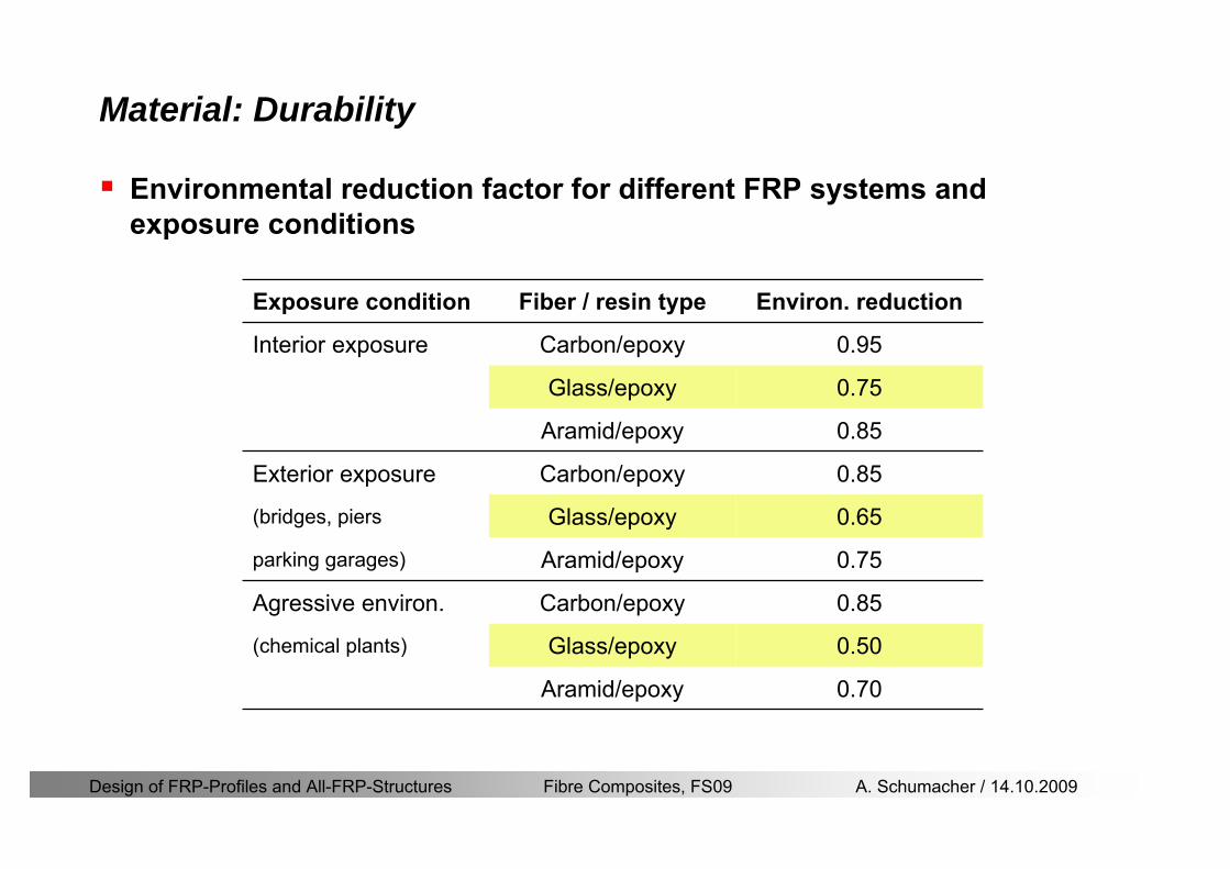
Design of FRP-Profiles and All-FRP-Structures Fibre Composites FS09 A Schumacher 14102009
Material Durability
Environmental reduction factor for different FRP systems and exposure conditions
070Aramidepoxy
050Glassepoxy(chemical plants)
085CarbonepoxyAgressive environ
075Aramidepoxyparking garages)
065Glassepoxy(bridges piers
085CarbonepoxyExterior exposure
085Aramidepoxy
075Glassepoxy
095CarbonepoxyInterior exposure
Environ reductionFiber resin typeExposure condition
Design of FRP-Profiles and All-FRP-Structures Fibre Composites FS09 A Schumacher 14102009
Material Durability
GFRP is more susceptible to degradation than CFRP by the following effects
alkaline effects (caution when GFRP in contact with concrete)acid effectssalt effectsfatigueUV radiation
Fire protection is a major (unsolved) issue for (G)FRP structural elements and components
Smoke generation and toxicity must be consideredStrength of GFRP is affected by fatigue loading(more than CFRP)
Design of FRP-Profiles and All-FRP-Structures Fibre Composites FS09 A Schumacher 14102009
Material Manufacturers
GFRP profiles available on stock
In Europe two companies pultrude FRP-Profiles
Fiberline Composites Denmarkwwwfiberlinecom
Fiberline Design Manual (wwwfiberlinedk)rarr helpful tool to design structures
(material properties geometries connections hellip)
Top Glass Italywwwtopglassit
Design of FRP-Profiles and All-FRP-Structures Fibre Composites FS09 A Schumacher 14102009
Material Manufacturers
GFRP profiles available on stock
In North America
Strongwell USAwwwstrongwellcom
Creative Pultrusions USAwwwcreativepultrusionscom
Bedford Reinforced Plastics USAwwwbedfordplasticscom
Design of FRP-Profiles and All-FRP-Structures Fibre Composites FS09 A Schumacher 14102009
Design Concept
Design of FRP-Profiles and All-FRP-Structures Fibre Composites FS09 A Schumacher 14102009
Design Concept Basic Assumptions
Definitions and directions
Design of FRP-Profiles and All-FRP-Structures Fibre Composites FS09 A Schumacher 14102009
Design Concept
Codes
Every manufacturer has its own profile design rarr No European Design Code is available (only EN13706 about testing and notation)
There exists European guidelines EUROCOMP 1996 Design CodeEUROCOMP 1996 Handbook
Fiberline Design Manual is based on Eurocomp 1996
Design concept (according to Eurocodes and Swisscodes)
Partial safety factors
Measured material parameters
Rules for bolted connections
Design of FRP-Profiles and All-FRP-Structures Fibre Composites FS09 A Schumacher 14102009
Design Concept
Concept of Limit State Design (According to Euro Codes and Swiss Codes)
Ultimate limit stress
Ed le Rd
Ed hellip Calculated stress (including load factors) hellip SIA260 261
Rd hellip Rated value of the resistance capability
where
Rk hellip the calculated resistance capability
kd mγ=
RR
Design of FRP-Profiles and All-FRP-Structures Fibre Composites FS09 A Schumacher 14102009
101020Production process
Operating temperature
111116Degree of postcuring
115115225Derivation of mat properties
FiberlineMinMaxDescriptionCoefficient
Design Concept
Reduction coefficient m m1 m2 m3 m4γ γ γ γ γ= sdot sdot sdot
m1γ
m2γ
m3γ
m4γ
mγ mγ
31312580
2510-20 +60
Long-term loadShort-term load
Operatingtemperature degC m4γ
Design of FRP-Profiles and All-FRP-Structures Fibre Composites FS09 A Schumacher 14102009
Design Concept
Serviceability limit states
Ed le Cd
Ed hellip the crucial action effect due to the load cases considered inthe investigated dimensioning situation Typically maximaldeflection response of the structure
Cd hellip corresponding serviceability limit SIA 261
Design of FRP-Profiles and All-FRP-Structures Fibre Composites FS09 A Schumacher 14102009
Design Concept Basic Assumptions
Material Properties stength values (Fiberline Profiles)
Design of FRP-Profiles and All-FRP-Structures Fibre Composites FS09 A Schumacher 14102009
Design Concept Basic Assumptions
Material Properties stiffness values (Fiberline Profiles)
Design of FRP-Profiles and All-FRP-Structures Fibre Composites FS09 A Schumacher 14102009
Design Concept Basic Assumptions
Typical data sheet of a profile (Fiberline I-Profile)
Design of FRP-Profiles and All-FRP-Structures Fibre Composites FS09 A Schumacher 14102009
Bending Beam
Design of FRP-Profiles and All-FRP-Structures Fibre Composites FS09 A Schumacher 14102009
Bending Beam Design of hellip
Calculate bending moments Md and shear forces Qd acting on the profile using the partial coefficient (SIA 260 261)
Ultimate limit state
Bending
Shear
Ak hellip relevant shear area
d max d max 0max
M MW Wy z b
mzy
fσ γ
⎛ ⎞⎜ ⎟⎜ ⎟⎜ ⎟⎜ ⎟⎝ ⎠
deg= + le
d maxmax
kyAy
m
Q fττ γ= le
Design of FRP-Profiles and All-FRP-Structures Fibre Composites FS09 A Schumacher 14102009
Bending Beam Design of hellip
Serviceability limit state
Deflection limit
hellip typically selected between 200 and 400given by SIA 261 or the building owner
hellip calculated including shear deformations
Vibrations
Light-weighted and lsquosoftrsquo structures are susceptible to vibrations (traffic wind the movement of people hellip)
max 1wL αlt
α
maxw
Design of FRP-Profiles and All-FRP-Structures Fibre Composites FS09 A Schumacher 14102009
Bending Beam Timoshenko Theory
Pultruded profiles have a low shear modulus rarr shear deformation must be taken into account
Several bending theories have been published for beams
Euler-Bernoulli theory (1702)
Timoshenko theory (1968)
Higher order beam theory
A simply supported beam with a symmetric cross-section is discussed
Design of FRP-Profiles and All-FRP-Structures Fibre Composites FS09 A Schumacher 14102009
Bending Beam Timoshenko Theory
Cross-sections planeand perpendicular
1 degree of freedom
w
Cross-sections plane butNOT perpendicular
2 degrees of freedom
w and ψ
Cross-sections do NOTremain plane
3+ degrees of freedom
w ψ and hellip
Design of FRP-Profiles and All-FRP-Structures Fibre Composites FS09 A Schumacher 14102009
Bending Beam Euler vs Timoshenko Theory
Kinematic relationships
( )( )
( )
2 0
x x
y
xx xx
yxxy
u y w xu w x
u y w xxuu
y x
ε
ε
=minus sdot=
part= =minus sdotpartpartpart= + =
part part
( )( )
( )
2 ( ) ( )
x
y
xx x
yxxy x
u y xu w x
u y xxuu x w xy x
ψ
ε ψ
ε ψ
=minus sdot=
part= =minus sdotpartpartpart= + =minus +
part part
Hookrsquos law
0degE and G 2x x xy xyσ ε τ ε= sdot = sdot
z0deg E Iz x xxQS
M y dydz wσ= minus sdot sdot = sdot sdotintint
( )
z0deg E I
z x xQS
y xQS
M y dydz
Q dydz w GA
σ ψ
κ τ ψ κ
= minus sdot sdot = sdot
= sdot = minus sdot sdot
intint
intint
Design of FRP-Profiles and All-FRP-Structures Fibre Composites FS09 A Schumacher 14102009
Bending Beam Euler vs Timoshenko Theory
Equilibrium
Solution for the simply supported beam (distributed load)
In a first approximation the deflections are calculated by direct integration of
z0deg
( ) E IxxM xw = sdot
( )( )z0deg
( ) E I 0x
x
xx x
xx x
q x w GAw GA
QM Q
ψ κψ ψ κ
minus minus sdot sdot
sdot + minus sdot sdot
=minus =
= =minus
Equilibrium on an infinitesimal beam element
Coupled second order differential equation
21 1( ) (0) 0 and ( ) 02 2
M x qLx qx w w L= minus = =
( )3 2 3
0deg z
( ) 224 E Iqxw x L Lx x= sdot minus +sdot sdot
2
0deg z
1 1 1E I 2 2xxw qLx qx⎛ ⎞= minus⎜ ⎟sdot ⎝ ⎠
(0) 0 and ( ) 0(0) 0 (0) 0 and ( ) 0 ( ) 0 x x
w w LM M L Lψ ψ
= == rarr = = rarr =
Functions4 3 2
1 2 3 4 53 2
1 2 3 4
( )
( )
w x A x A x A x A x A
x B x B x B x Bψ
= + + + +
= + + +
Design of FRP-Profiles and All-FRP-Structures Fibre Composites FS09 A Schumacher 14102009
Put in and solve for the coefficients rarr
Bending Beam Euler vs Timoshenko Theory
Use the boundary conditions and the second differential eq to calculate A1 ndash A5
( )0deg z E I 0xx xw GAψ ψ κsdot + minus sdot sdot =
1 01 1 3 3
2 02 2 4 4
24 E I4 2GA
6 E I3 GA
z
z
AB A B A
AB A B A
κ
κ
deg
deg
sdot= minus = minus minus
sdotsdot
= minus = minus minussdot
( ) ( )( )2 2
0
( )2 GA 24 E Iz
qx L x L Lx xqx L xw x
κ deg
minus + minusminus= +
sdot sdot sdot
Deflection at midspan
4
0
52 384 E Iz
qLLw⎛ ⎞⎜ ⎟⎝ ⎠
deg
sdot= sdot4 2
0
52 384 E I 8 GAz
qL q LLw κ⎛ ⎞ +⎜ ⎟⎝ ⎠
deg
sdot sdot= sdot sdot sdot
Design of FRP-Profiles and All-FRP-Structures Fibre Composites FS09 A Schumacher 14102009
General expression for the total beam deflection as a sum of the deflection due to bending and shear
GAxf
IExfxwz sdot+=
deg κ)()()( 2
0
1
Cantilever beam
Simply supported
Concentrated load (P)
Uniformly distr load (q)
Concentrated load (P)
Uniformly distr load (q)
Beam )( max1 wf
3845 4qLsdot
48
3PL
8
4qL
3
3PL
)( max1 wf
8
2qL
4PL
2
2qL
PL
)( maxwx
2L
2L
L
L
Bending Beam Euler vs Timoshenko Theory
Design of FRP-Profiles and All-FRP-Structures Fibre Composites FS09 A Schumacher 14102009
Bending Beam Euler vs Timoshenko Theory
Example influence of the shear deformation
Profile 300 x 150 mm I-beam
Load uniformly distributed
General rule of thumbfor GFRP beams withspandepth gt 25 sheardeformation can beignored
Design of FRP-Profiles and All-FRP-Structures Fibre Composites FS09 A Schumacher 14102009
Bending Beam Example
Choose an appropriate Profile for the following specifications
1 Deflections and loading
=
=
==
1300 rarr wmax=001 mwmaxL
10 kNmqdser
13 kNmqduls
30 mL
max
4 2
0
5384 E I 8 GA
d ser d serz
q L q Lw κ+
deg
sdot sdot= sdot sdot sdot
2
maxz8 2 I
d ulsq L hσ sdot= sdot
maxky
12 Ad ulsq L
τ sdot=
Design of FRP-Profiles and All-FRP-Structures Fibre Composites FS09 A Schumacher 14102009
Bending Beam Example
2 Find a profile with sufficient bending stiffness
Shear deformations are neglected in a first step
rarr from specification table choose I 240x120x12 rarr
3 Check the bending and shear stresses
6 24
0 max
1054 10 Nm5
E I 384d ser
zq Lwdeg = sdot
sdotsdotge
6 20 1369 10 NmE Izdeg = sdot
2
maxz
358 MPa8 2 Id ulsq L hσ sdot= =sdot
max
ky
1 71 MPa2 Ad ulsq L
τ sdot= =
0 185 MPab df degle =
20 MPadfτle =
Design of FRP-Profiles and All-FRP-Structures Fibre Composites FS09 A Schumacher 14102009
Bending Beam Example
m10398384
5 32
0
4
maxminus
deg
sdot=sdotsdotsdot
+sdot
sdot=
GALq
IELq
w serd
z
serd
κ
4 Check deflection (including shear deformation)
5 Remarks
The design of GFRP-profiles is mostly driven by serviceability criteria
Start the design iteration procedure using the maximal deflection criterion
max 001 mwle =
m10198384
5 32
0
4
maxminus
deg
sdot=sdot
sdot+
sdotsdot
=web
serd
z
serd
GALq
IELq
w
(77 mm) (16 mm)
Design of FRP-Profiles and All-FRP-Structures Fibre Composites FS09 A Schumacher 14102009
Bending Beam Stability problems
Lateral-torsional bucklingFlange (compressive) displace laterally to the transverse load direction
Torsional stiffness is too low (especially for open section profiles)
Theoretical calculations or design measuresrarr see eg LP Kollaacuter 2003
Mechanics of composite structuresExample
Compressive flanges are kept in place by connection to the bridge deck
Design of FRP-Profiles and All-FRP-Structures Fibre Composites FS09 A Schumacher 14102009
Bending Beam Stability problems
Flange (compressive) displaces in the direction of the transverse load
Low bending stiffness perpendicular to the pultrusion direction
Weak fiber mats
Local buckling of walls due to in-plane compression
Local buckling of walls due to in-plane shear
Web crushing and web buckling in transverse direction
Design of FRP-Profiles and All-FRP-Structures Fibre Composites FS09 A Schumacher 14102009
Axial Members
Design of FRP-Profiles and All-FRP-Structures Fibre Composites FS09 A Schumacher 14102009
Axial Members Tension
Ultimate limit state under axial tension Nd
Serviceability limit state
Remark The critical aspect of axial members in tension are neither the serviceability nor the ultimate limit state Critical is the load transfer to the GFRP profile
0NdA
tm
fγ
degle
0deg
N LE Axδ sdot= sdot
Design of FRP-Profiles and All-FRP-Structures Fibre Composites FS09 A Schumacher 14102009
Axial Members Compression
Ultimate limit state under axial compression Nd
hellip maximal compressive load
hellip Euler load
hellip Buckling length for columns
hellip coefficient for Youngrsquos modulus = 13
cc
Euler
FNd F1 N
le+
c0degC
A fF
mγsdot
=
20
Euler 2
Nm E k
E IL
πγ
degsdot sdot=
sdot
kL
m Eγ
Design of FRP-Profiles and All-FRP-Structures Fibre Composites FS09 A Schumacher 14102009
Axial Members Compression
The influence of shear deformation should be considered but in the most cases the influence will be small (less than 5)
Local buckling should be considered for short columns
For more information on the various buckling modes and effects rarr see LP Kollaacuter 2003 Mechanics of composite structures
Global buckling Local buckling
Design of FRP-Profiles and All-FRP-Structures Fibre Composites FS09 A Schumacher 14102009
Connections
Design of FRP-Profiles and All-FRP-Structures Fibre Composites FS09 A Schumacher 14102009
Connections Introduction
Design of FRP-Profiles and All-FRP-Structures Fibre Composites FS09 A Schumacher 14102009
Connections Introduction
(from Eurocomp Design Code 1996)
Design of FRP-Profiles and All-FRP-Structures Fibre Composites FS09 A Schumacher 14102009
Connections Bolted joints
Bolts = Stress concentration in the profile and the bolt
It is necessary to ensure that the bolts and the profilecan withstand this concentrated local stress compression
It is necessary to ensure that the region surroundinga group of bolts will not be torn out of the profile
Basic failure modesin bolted shearconnections
bolt shear failure
Design of FRP-Profiles and All-FRP-Structures Fibre Composites FS09 A Schumacher 14102009
Connections Bolted joints
The design procedure is comparable to the one for steel connections but since there exist no standard GFRP material rarr each manufacturer has its own design rules for bolted joints
IMPORTANT REMARKS
The direction of pultrusion and the direction of the force is RELEVANT(anisotropic material)
Use stainless or galvanised steel
Do not cut threads in the composite material
Use screws with shafts
Design of FRP-Profiles and All-FRP-Structures Fibre Composites FS09 A Schumacher 14102009
Calculation of load bearing capacity of bolts
Shear in longitudinal direction (0deg)
Shear in transverse direction (90deg)
Tensile force
Minimum distances
Connections Bolted joints (Fiberline recommendations)
Design of FRP-Profiles and All-FRP-Structures Fibre Composites FS09 A Schumacher 14102009
Joint capacity tables available for shear and tension
m
150 MPa( 13)B d
d tP γsdot sdot=
=
Shear in longitudinal direction 0deg
m
70 MPa( 13)B d
d tP γsdot sdot=
=
Shear in transverse direction 90deg
Connections Bolted joints (Fiberline recommendations)
Design of FRP-Profiles and All-FRP-Structures Fibre Composites FS09 A Schumacher 14102009
Bolted connection in shear eg shear in longitudinal direction
Connections Bolted joints (Fiberline recommendations)
γmPBolt le dt720 MPaγmPBolt le dt240 MPa
γmPBolt le dt240 MPa γmPBolt le dt240 MPaγmPBolt le dt150 MPa
Design of FRP-Profiles and All-FRP-Structures Fibre Composites FS09 A Schumacher 14102009
Bolted connections in tension
Static conditions
Bolt Tearing of bolt in threaded cross-section
Laminate Shear fracture at rim of washer
Geometry and strength
Diameter of washer2d
Tensile strength of bolt hellipfyk
Shear strength of laminatehellipfτ
Thickness of laminatet
Stress area of the boltAs
Diameter of the boltd
s ykd m
A fP γ
sdotle
2d m
d t fP τπγ
sdot sdot sdot sdotle
Connections Bolted joints (Fiberline recommendations)
Design of FRP-Profiles and All-FRP-Structures Fibre Composites FS09 A Schumacher 14102009
Connections Bonded joints
Using an adhesive agent for joining profiles can have advantages
Easy to use easy to make aesthetic joints
Typically more rigid than bolted joints
Glued joints subjected to dynamic loads are good
But be careful hellipAdhesive agents have properties that depend on time temperature humidity hellip
Failure in glued joints takes place suddenly (brittle behaviour)
The load-bearing capacity is not proportional to the area which is glued
The design of bonded joints may be based onAnalytical models for plate-to-plate connections (see Eurocomp 1996 Design Code)
Design guidelines supplemented by testing
Finite element analysis
Design of FRP-Profiles and All-FRP-Structures Fibre Composites FS09 A Schumacher 14102009
Connections Bonded joints
A bonded joint has the following three primary failure modes
adhesive failure
cohesive failure of adhesive
cohesive failure of adherend
The design of any bonded joint shall satisfy the following conditions
allowable shear stress in the adhesive is not exceeded
allowable tensile (peel) stress in the adhesive is not exceeded
allowable through-thickness tensile stress of the adhesive is not exceeded
allowable in-plane shear stress of the adherend should not be exceeded
The calculation of the stresses has to be done very carefully Often calculations are supplemented by testing
Design of FRP-Profiles and All-FRP-Structures Fibre Composites FS09 A Schumacher 14102009
Connections Bonded joints
Different types of bonded joint configurations
Research on bonded joints for structuralapplications
Design of FRP-Profiles and All-FRP-Structures Fibre Composites FS09 A Schumacher 14102009
Connections Other joints
Brackets for assembly (Fiberline)
Custom pultruded connections
Design of FRP-Profiles and All-FRP-Structures Fibre Composites FS09 A Schumacher 14102009
GFRP Some final remarks
Perpendicular to the direction of pultrusion the material is WEAK and SOFTrarr avoid such loadings if possible
In order to use pultruded GFRP-profiles economically the design must be done in a clever way eg for bridges the railings should be used as part of the load-bearing structure
GFRP structures are very light rarr vibration problems may occur
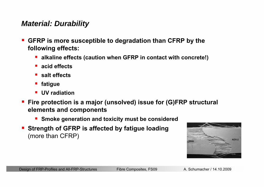
Design of FRP-Profiles and All-FRP-Structures Fibre Composites FS09 A Schumacher 14102009
Material Durability
GFRP is more susceptible to degradation than CFRP by the following effects
alkaline effects (caution when GFRP in contact with concrete)acid effectssalt effectsfatigueUV radiation
Fire protection is a major (unsolved) issue for (G)FRP structural elements and components
Smoke generation and toxicity must be consideredStrength of GFRP is affected by fatigue loading(more than CFRP)
Design of FRP-Profiles and All-FRP-Structures Fibre Composites FS09 A Schumacher 14102009
Material Manufacturers
GFRP profiles available on stock
In Europe two companies pultrude FRP-Profiles
Fiberline Composites Denmarkwwwfiberlinecom
Fiberline Design Manual (wwwfiberlinedk)rarr helpful tool to design structures
(material properties geometries connections hellip)
Top Glass Italywwwtopglassit
Design of FRP-Profiles and All-FRP-Structures Fibre Composites FS09 A Schumacher 14102009
Material Manufacturers
GFRP profiles available on stock
In North America
Strongwell USAwwwstrongwellcom
Creative Pultrusions USAwwwcreativepultrusionscom
Bedford Reinforced Plastics USAwwwbedfordplasticscom
Design of FRP-Profiles and All-FRP-Structures Fibre Composites FS09 A Schumacher 14102009
Design Concept
Design of FRP-Profiles and All-FRP-Structures Fibre Composites FS09 A Schumacher 14102009
Design Concept Basic Assumptions
Definitions and directions
Design of FRP-Profiles and All-FRP-Structures Fibre Composites FS09 A Schumacher 14102009
Design Concept
Codes
Every manufacturer has its own profile design rarr No European Design Code is available (only EN13706 about testing and notation)
There exists European guidelines EUROCOMP 1996 Design CodeEUROCOMP 1996 Handbook
Fiberline Design Manual is based on Eurocomp 1996
Design concept (according to Eurocodes and Swisscodes)
Partial safety factors
Measured material parameters
Rules for bolted connections
Design of FRP-Profiles and All-FRP-Structures Fibre Composites FS09 A Schumacher 14102009
Design Concept
Concept of Limit State Design (According to Euro Codes and Swiss Codes)
Ultimate limit stress
Ed le Rd
Ed hellip Calculated stress (including load factors) hellip SIA260 261
Rd hellip Rated value of the resistance capability
where
Rk hellip the calculated resistance capability
kd mγ=
RR
Design of FRP-Profiles and All-FRP-Structures Fibre Composites FS09 A Schumacher 14102009
101020Production process
Operating temperature
111116Degree of postcuring
115115225Derivation of mat properties
FiberlineMinMaxDescriptionCoefficient
Design Concept
Reduction coefficient m m1 m2 m3 m4γ γ γ γ γ= sdot sdot sdot
m1γ
m2γ
m3γ
m4γ
mγ mγ
31312580
2510-20 +60
Long-term loadShort-term load
Operatingtemperature degC m4γ
Design of FRP-Profiles and All-FRP-Structures Fibre Composites FS09 A Schumacher 14102009
Design Concept
Serviceability limit states
Ed le Cd
Ed hellip the crucial action effect due to the load cases considered inthe investigated dimensioning situation Typically maximaldeflection response of the structure
Cd hellip corresponding serviceability limit SIA 261
Design of FRP-Profiles and All-FRP-Structures Fibre Composites FS09 A Schumacher 14102009
Design Concept Basic Assumptions
Material Properties stength values (Fiberline Profiles)
Design of FRP-Profiles and All-FRP-Structures Fibre Composites FS09 A Schumacher 14102009
Design Concept Basic Assumptions
Material Properties stiffness values (Fiberline Profiles)
Design of FRP-Profiles and All-FRP-Structures Fibre Composites FS09 A Schumacher 14102009
Design Concept Basic Assumptions
Typical data sheet of a profile (Fiberline I-Profile)
Design of FRP-Profiles and All-FRP-Structures Fibre Composites FS09 A Schumacher 14102009
Bending Beam
Design of FRP-Profiles and All-FRP-Structures Fibre Composites FS09 A Schumacher 14102009
Bending Beam Design of hellip
Calculate bending moments Md and shear forces Qd acting on the profile using the partial coefficient (SIA 260 261)
Ultimate limit state
Bending
Shear
Ak hellip relevant shear area
d max d max 0max
M MW Wy z b
mzy
fσ γ
⎛ ⎞⎜ ⎟⎜ ⎟⎜ ⎟⎜ ⎟⎝ ⎠
deg= + le
d maxmax
kyAy
m
Q fττ γ= le
Design of FRP-Profiles and All-FRP-Structures Fibre Composites FS09 A Schumacher 14102009
Bending Beam Design of hellip
Serviceability limit state
Deflection limit
hellip typically selected between 200 and 400given by SIA 261 or the building owner
hellip calculated including shear deformations
Vibrations
Light-weighted and lsquosoftrsquo structures are susceptible to vibrations (traffic wind the movement of people hellip)
max 1wL αlt
α
maxw
Design of FRP-Profiles and All-FRP-Structures Fibre Composites FS09 A Schumacher 14102009
Bending Beam Timoshenko Theory
Pultruded profiles have a low shear modulus rarr shear deformation must be taken into account
Several bending theories have been published for beams
Euler-Bernoulli theory (1702)
Timoshenko theory (1968)
Higher order beam theory
A simply supported beam with a symmetric cross-section is discussed
Design of FRP-Profiles and All-FRP-Structures Fibre Composites FS09 A Schumacher 14102009
Bending Beam Timoshenko Theory
Cross-sections planeand perpendicular
1 degree of freedom
w
Cross-sections plane butNOT perpendicular
2 degrees of freedom
w and ψ
Cross-sections do NOTremain plane
3+ degrees of freedom
w ψ and hellip
Design of FRP-Profiles and All-FRP-Structures Fibre Composites FS09 A Schumacher 14102009
Bending Beam Euler vs Timoshenko Theory
Kinematic relationships
( )( )
( )
2 0
x x
y
xx xx
yxxy
u y w xu w x
u y w xxuu
y x
ε
ε
=minus sdot=
part= =minus sdotpartpartpart= + =
part part
( )( )
( )
2 ( ) ( )
x
y
xx x
yxxy x
u y xu w x
u y xxuu x w xy x
ψ
ε ψ
ε ψ
=minus sdot=
part= =minus sdotpartpartpart= + =minus +
part part
Hookrsquos law
0degE and G 2x x xy xyσ ε τ ε= sdot = sdot
z0deg E Iz x xxQS
M y dydz wσ= minus sdot sdot = sdot sdotintint
( )
z0deg E I
z x xQS
y xQS
M y dydz
Q dydz w GA
σ ψ
κ τ ψ κ
= minus sdot sdot = sdot
= sdot = minus sdot sdot
intint
intint
Design of FRP-Profiles and All-FRP-Structures Fibre Composites FS09 A Schumacher 14102009
Bending Beam Euler vs Timoshenko Theory
Equilibrium
Solution for the simply supported beam (distributed load)
In a first approximation the deflections are calculated by direct integration of
z0deg
( ) E IxxM xw = sdot
( )( )z0deg
( ) E I 0x
x
xx x
xx x
q x w GAw GA
QM Q
ψ κψ ψ κ
minus minus sdot sdot
sdot + minus sdot sdot
=minus =
= =minus
Equilibrium on an infinitesimal beam element
Coupled second order differential equation
21 1( ) (0) 0 and ( ) 02 2
M x qLx qx w w L= minus = =
( )3 2 3
0deg z
( ) 224 E Iqxw x L Lx x= sdot minus +sdot sdot
2
0deg z
1 1 1E I 2 2xxw qLx qx⎛ ⎞= minus⎜ ⎟sdot ⎝ ⎠
(0) 0 and ( ) 0(0) 0 (0) 0 and ( ) 0 ( ) 0 x x
w w LM M L Lψ ψ
= == rarr = = rarr =
Functions4 3 2
1 2 3 4 53 2
1 2 3 4
( )
( )
w x A x A x A x A x A
x B x B x B x Bψ
= + + + +
= + + +
Design of FRP-Profiles and All-FRP-Structures Fibre Composites FS09 A Schumacher 14102009
Put in and solve for the coefficients rarr
Bending Beam Euler vs Timoshenko Theory
Use the boundary conditions and the second differential eq to calculate A1 ndash A5
( )0deg z E I 0xx xw GAψ ψ κsdot + minus sdot sdot =
1 01 1 3 3
2 02 2 4 4
24 E I4 2GA
6 E I3 GA
z
z
AB A B A
AB A B A
κ
κ
deg
deg
sdot= minus = minus minus
sdotsdot
= minus = minus minussdot
( ) ( )( )2 2
0
( )2 GA 24 E Iz
qx L x L Lx xqx L xw x
κ deg
minus + minusminus= +
sdot sdot sdot
Deflection at midspan
4
0
52 384 E Iz
qLLw⎛ ⎞⎜ ⎟⎝ ⎠
deg
sdot= sdot4 2
0
52 384 E I 8 GAz
qL q LLw κ⎛ ⎞ +⎜ ⎟⎝ ⎠
deg
sdot sdot= sdot sdot sdot
Design of FRP-Profiles and All-FRP-Structures Fibre Composites FS09 A Schumacher 14102009
General expression for the total beam deflection as a sum of the deflection due to bending and shear
GAxf
IExfxwz sdot+=
deg κ)()()( 2
0
1
Cantilever beam
Simply supported
Concentrated load (P)
Uniformly distr load (q)
Concentrated load (P)
Uniformly distr load (q)
Beam )( max1 wf
3845 4qLsdot
48
3PL
8
4qL
3
3PL
)( max1 wf
8
2qL
4PL
2
2qL
PL
)( maxwx
2L
2L
L
L
Bending Beam Euler vs Timoshenko Theory
Design of FRP-Profiles and All-FRP-Structures Fibre Composites FS09 A Schumacher 14102009
Bending Beam Euler vs Timoshenko Theory
Example influence of the shear deformation
Profile 300 x 150 mm I-beam
Load uniformly distributed
General rule of thumbfor GFRP beams withspandepth gt 25 sheardeformation can beignored
Design of FRP-Profiles and All-FRP-Structures Fibre Composites FS09 A Schumacher 14102009
Bending Beam Example
Choose an appropriate Profile for the following specifications
1 Deflections and loading
=
=
==
1300 rarr wmax=001 mwmaxL
10 kNmqdser
13 kNmqduls
30 mL
max
4 2
0
5384 E I 8 GA
d ser d serz
q L q Lw κ+
deg
sdot sdot= sdot sdot sdot
2
maxz8 2 I
d ulsq L hσ sdot= sdot
maxky
12 Ad ulsq L
τ sdot=
Design of FRP-Profiles and All-FRP-Structures Fibre Composites FS09 A Schumacher 14102009
Bending Beam Example
2 Find a profile with sufficient bending stiffness
Shear deformations are neglected in a first step
rarr from specification table choose I 240x120x12 rarr
3 Check the bending and shear stresses
6 24
0 max
1054 10 Nm5
E I 384d ser
zq Lwdeg = sdot
sdotsdotge
6 20 1369 10 NmE Izdeg = sdot
2
maxz
358 MPa8 2 Id ulsq L hσ sdot= =sdot
max
ky
1 71 MPa2 Ad ulsq L
τ sdot= =
0 185 MPab df degle =
20 MPadfτle =
Design of FRP-Profiles and All-FRP-Structures Fibre Composites FS09 A Schumacher 14102009
Bending Beam Example
m10398384
5 32
0
4
maxminus
deg
sdot=sdotsdotsdot
+sdot
sdot=
GALq
IELq
w serd
z
serd
κ
4 Check deflection (including shear deformation)
5 Remarks
The design of GFRP-profiles is mostly driven by serviceability criteria
Start the design iteration procedure using the maximal deflection criterion
max 001 mwle =
m10198384
5 32
0
4
maxminus
deg
sdot=sdot
sdot+
sdotsdot
=web
serd
z
serd
GALq
IELq
w
(77 mm) (16 mm)
Design of FRP-Profiles and All-FRP-Structures Fibre Composites FS09 A Schumacher 14102009
Bending Beam Stability problems
Lateral-torsional bucklingFlange (compressive) displace laterally to the transverse load direction
Torsional stiffness is too low (especially for open section profiles)
Theoretical calculations or design measuresrarr see eg LP Kollaacuter 2003
Mechanics of composite structuresExample
Compressive flanges are kept in place by connection to the bridge deck
Design of FRP-Profiles and All-FRP-Structures Fibre Composites FS09 A Schumacher 14102009
Bending Beam Stability problems
Flange (compressive) displaces in the direction of the transverse load
Low bending stiffness perpendicular to the pultrusion direction
Weak fiber mats
Local buckling of walls due to in-plane compression
Local buckling of walls due to in-plane shear
Web crushing and web buckling in transverse direction
Design of FRP-Profiles and All-FRP-Structures Fibre Composites FS09 A Schumacher 14102009
Axial Members
Design of FRP-Profiles and All-FRP-Structures Fibre Composites FS09 A Schumacher 14102009
Axial Members Tension
Ultimate limit state under axial tension Nd
Serviceability limit state
Remark The critical aspect of axial members in tension are neither the serviceability nor the ultimate limit state Critical is the load transfer to the GFRP profile
0NdA
tm
fγ
degle
0deg
N LE Axδ sdot= sdot
Design of FRP-Profiles and All-FRP-Structures Fibre Composites FS09 A Schumacher 14102009
Axial Members Compression
Ultimate limit state under axial compression Nd
hellip maximal compressive load
hellip Euler load
hellip Buckling length for columns
hellip coefficient for Youngrsquos modulus = 13
cc
Euler
FNd F1 N
le+
c0degC
A fF
mγsdot
=
20
Euler 2
Nm E k
E IL
πγ
degsdot sdot=
sdot
kL
m Eγ
Design of FRP-Profiles and All-FRP-Structures Fibre Composites FS09 A Schumacher 14102009
Axial Members Compression
The influence of shear deformation should be considered but in the most cases the influence will be small (less than 5)
Local buckling should be considered for short columns
For more information on the various buckling modes and effects rarr see LP Kollaacuter 2003 Mechanics of composite structures
Global buckling Local buckling
Design of FRP-Profiles and All-FRP-Structures Fibre Composites FS09 A Schumacher 14102009
Connections
Design of FRP-Profiles and All-FRP-Structures Fibre Composites FS09 A Schumacher 14102009
Connections Introduction
Design of FRP-Profiles and All-FRP-Structures Fibre Composites FS09 A Schumacher 14102009
Connections Introduction
(from Eurocomp Design Code 1996)
Design of FRP-Profiles and All-FRP-Structures Fibre Composites FS09 A Schumacher 14102009
Connections Bolted joints
Bolts = Stress concentration in the profile and the bolt
It is necessary to ensure that the bolts and the profilecan withstand this concentrated local stress compression
It is necessary to ensure that the region surroundinga group of bolts will not be torn out of the profile
Basic failure modesin bolted shearconnections
bolt shear failure
Design of FRP-Profiles and All-FRP-Structures Fibre Composites FS09 A Schumacher 14102009
Connections Bolted joints
The design procedure is comparable to the one for steel connections but since there exist no standard GFRP material rarr each manufacturer has its own design rules for bolted joints
IMPORTANT REMARKS
The direction of pultrusion and the direction of the force is RELEVANT(anisotropic material)
Use stainless or galvanised steel
Do not cut threads in the composite material
Use screws with shafts
Design of FRP-Profiles and All-FRP-Structures Fibre Composites FS09 A Schumacher 14102009
Calculation of load bearing capacity of bolts
Shear in longitudinal direction (0deg)
Shear in transverse direction (90deg)
Tensile force
Minimum distances
Connections Bolted joints (Fiberline recommendations)
Design of FRP-Profiles and All-FRP-Structures Fibre Composites FS09 A Schumacher 14102009
Joint capacity tables available for shear and tension
m
150 MPa( 13)B d
d tP γsdot sdot=
=
Shear in longitudinal direction 0deg
m
70 MPa( 13)B d
d tP γsdot sdot=
=
Shear in transverse direction 90deg
Connections Bolted joints (Fiberline recommendations)
Design of FRP-Profiles and All-FRP-Structures Fibre Composites FS09 A Schumacher 14102009
Bolted connection in shear eg shear in longitudinal direction
Connections Bolted joints (Fiberline recommendations)
γmPBolt le dt720 MPaγmPBolt le dt240 MPa
γmPBolt le dt240 MPa γmPBolt le dt240 MPaγmPBolt le dt150 MPa
Design of FRP-Profiles and All-FRP-Structures Fibre Composites FS09 A Schumacher 14102009
Bolted connections in tension
Static conditions
Bolt Tearing of bolt in threaded cross-section
Laminate Shear fracture at rim of washer
Geometry and strength
Diameter of washer2d
Tensile strength of bolt hellipfyk
Shear strength of laminatehellipfτ
Thickness of laminatet
Stress area of the boltAs
Diameter of the boltd
s ykd m
A fP γ
sdotle
2d m
d t fP τπγ
sdot sdot sdot sdotle
Connections Bolted joints (Fiberline recommendations)
Design of FRP-Profiles and All-FRP-Structures Fibre Composites FS09 A Schumacher 14102009
Connections Bonded joints
Using an adhesive agent for joining profiles can have advantages
Easy to use easy to make aesthetic joints
Typically more rigid than bolted joints
Glued joints subjected to dynamic loads are good
But be careful hellipAdhesive agents have properties that depend on time temperature humidity hellip
Failure in glued joints takes place suddenly (brittle behaviour)
The load-bearing capacity is not proportional to the area which is glued
The design of bonded joints may be based onAnalytical models for plate-to-plate connections (see Eurocomp 1996 Design Code)
Design guidelines supplemented by testing
Finite element analysis
Design of FRP-Profiles and All-FRP-Structures Fibre Composites FS09 A Schumacher 14102009
Connections Bonded joints
A bonded joint has the following three primary failure modes
adhesive failure
cohesive failure of adhesive
cohesive failure of adherend
The design of any bonded joint shall satisfy the following conditions
allowable shear stress in the adhesive is not exceeded
allowable tensile (peel) stress in the adhesive is not exceeded
allowable through-thickness tensile stress of the adhesive is not exceeded
allowable in-plane shear stress of the adherend should not be exceeded
The calculation of the stresses has to be done very carefully Often calculations are supplemented by testing
Design of FRP-Profiles and All-FRP-Structures Fibre Composites FS09 A Schumacher 14102009
Connections Bonded joints
Different types of bonded joint configurations
Research on bonded joints for structuralapplications
Design of FRP-Profiles and All-FRP-Structures Fibre Composites FS09 A Schumacher 14102009
Connections Other joints
Brackets for assembly (Fiberline)
Custom pultruded connections
Design of FRP-Profiles and All-FRP-Structures Fibre Composites FS09 A Schumacher 14102009
GFRP Some final remarks
Perpendicular to the direction of pultrusion the material is WEAK and SOFTrarr avoid such loadings if possible
In order to use pultruded GFRP-profiles economically the design must be done in a clever way eg for bridges the railings should be used as part of the load-bearing structure
GFRP structures are very light rarr vibration problems may occur
Design of FRP-Profiles and All-FRP-Structures Fibre Composites FS09 A Schumacher 14102009
Material Manufacturers
GFRP profiles available on stock
In Europe two companies pultrude FRP-Profiles
Fiberline Composites Denmarkwwwfiberlinecom
Fiberline Design Manual (wwwfiberlinedk)rarr helpful tool to design structures
(material properties geometries connections hellip)
Top Glass Italywwwtopglassit
Design of FRP-Profiles and All-FRP-Structures Fibre Composites FS09 A Schumacher 14102009
Material Manufacturers
GFRP profiles available on stock
In North America
Strongwell USAwwwstrongwellcom
Creative Pultrusions USAwwwcreativepultrusionscom
Bedford Reinforced Plastics USAwwwbedfordplasticscom
Design of FRP-Profiles and All-FRP-Structures Fibre Composites FS09 A Schumacher 14102009
Design Concept
Design of FRP-Profiles and All-FRP-Structures Fibre Composites FS09 A Schumacher 14102009
Design Concept Basic Assumptions
Definitions and directions
Design of FRP-Profiles and All-FRP-Structures Fibre Composites FS09 A Schumacher 14102009
Design Concept
Codes
Every manufacturer has its own profile design rarr No European Design Code is available (only EN13706 about testing and notation)
There exists European guidelines EUROCOMP 1996 Design CodeEUROCOMP 1996 Handbook
Fiberline Design Manual is based on Eurocomp 1996
Design concept (according to Eurocodes and Swisscodes)
Partial safety factors
Measured material parameters
Rules for bolted connections
Design of FRP-Profiles and All-FRP-Structures Fibre Composites FS09 A Schumacher 14102009
Design Concept
Concept of Limit State Design (According to Euro Codes and Swiss Codes)
Ultimate limit stress
Ed le Rd
Ed hellip Calculated stress (including load factors) hellip SIA260 261
Rd hellip Rated value of the resistance capability
where
Rk hellip the calculated resistance capability
kd mγ=
RR
Design of FRP-Profiles and All-FRP-Structures Fibre Composites FS09 A Schumacher 14102009
101020Production process
Operating temperature
111116Degree of postcuring
115115225Derivation of mat properties
FiberlineMinMaxDescriptionCoefficient
Design Concept
Reduction coefficient m m1 m2 m3 m4γ γ γ γ γ= sdot sdot sdot
m1γ
m2γ
m3γ
m4γ
mγ mγ
31312580
2510-20 +60
Long-term loadShort-term load
Operatingtemperature degC m4γ
Design of FRP-Profiles and All-FRP-Structures Fibre Composites FS09 A Schumacher 14102009
Design Concept
Serviceability limit states
Ed le Cd
Ed hellip the crucial action effect due to the load cases considered inthe investigated dimensioning situation Typically maximaldeflection response of the structure
Cd hellip corresponding serviceability limit SIA 261
Design of FRP-Profiles and All-FRP-Structures Fibre Composites FS09 A Schumacher 14102009
Design Concept Basic Assumptions
Material Properties stength values (Fiberline Profiles)
Design of FRP-Profiles and All-FRP-Structures Fibre Composites FS09 A Schumacher 14102009
Design Concept Basic Assumptions
Material Properties stiffness values (Fiberline Profiles)
Design of FRP-Profiles and All-FRP-Structures Fibre Composites FS09 A Schumacher 14102009
Design Concept Basic Assumptions
Typical data sheet of a profile (Fiberline I-Profile)
Design of FRP-Profiles and All-FRP-Structures Fibre Composites FS09 A Schumacher 14102009
Bending Beam
Design of FRP-Profiles and All-FRP-Structures Fibre Composites FS09 A Schumacher 14102009
Bending Beam Design of hellip
Calculate bending moments Md and shear forces Qd acting on the profile using the partial coefficient (SIA 260 261)
Ultimate limit state
Bending
Shear
Ak hellip relevant shear area
d max d max 0max
M MW Wy z b
mzy
fσ γ
⎛ ⎞⎜ ⎟⎜ ⎟⎜ ⎟⎜ ⎟⎝ ⎠
deg= + le
d maxmax
kyAy
m
Q fττ γ= le
Design of FRP-Profiles and All-FRP-Structures Fibre Composites FS09 A Schumacher 14102009
Bending Beam Design of hellip
Serviceability limit state
Deflection limit
hellip typically selected between 200 and 400given by SIA 261 or the building owner
hellip calculated including shear deformations
Vibrations
Light-weighted and lsquosoftrsquo structures are susceptible to vibrations (traffic wind the movement of people hellip)
max 1wL αlt
α
maxw
Design of FRP-Profiles and All-FRP-Structures Fibre Composites FS09 A Schumacher 14102009
Bending Beam Timoshenko Theory
Pultruded profiles have a low shear modulus rarr shear deformation must be taken into account
Several bending theories have been published for beams
Euler-Bernoulli theory (1702)
Timoshenko theory (1968)
Higher order beam theory
A simply supported beam with a symmetric cross-section is discussed
Design of FRP-Profiles and All-FRP-Structures Fibre Composites FS09 A Schumacher 14102009
Bending Beam Timoshenko Theory
Cross-sections planeand perpendicular
1 degree of freedom
w
Cross-sections plane butNOT perpendicular
2 degrees of freedom
w and ψ
Cross-sections do NOTremain plane
3+ degrees of freedom
w ψ and hellip
Design of FRP-Profiles and All-FRP-Structures Fibre Composites FS09 A Schumacher 14102009
Bending Beam Euler vs Timoshenko Theory
Kinematic relationships
( )( )
( )
2 0
x x
y
xx xx
yxxy
u y w xu w x
u y w xxuu
y x
ε
ε
=minus sdot=
part= =minus sdotpartpartpart= + =
part part
( )( )
( )
2 ( ) ( )
x
y
xx x
yxxy x
u y xu w x
u y xxuu x w xy x
ψ
ε ψ
ε ψ
=minus sdot=
part= =minus sdotpartpartpart= + =minus +
part part
Hookrsquos law
0degE and G 2x x xy xyσ ε τ ε= sdot = sdot
z0deg E Iz x xxQS
M y dydz wσ= minus sdot sdot = sdot sdotintint
( )
z0deg E I
z x xQS
y xQS
M y dydz
Q dydz w GA
σ ψ
κ τ ψ κ
= minus sdot sdot = sdot
= sdot = minus sdot sdot
intint
intint
Design of FRP-Profiles and All-FRP-Structures Fibre Composites FS09 A Schumacher 14102009
Bending Beam Euler vs Timoshenko Theory
Equilibrium
Solution for the simply supported beam (distributed load)
In a first approximation the deflections are calculated by direct integration of
z0deg
( ) E IxxM xw = sdot
( )( )z0deg
( ) E I 0x
x
xx x
xx x
q x w GAw GA
QM Q
ψ κψ ψ κ
minus minus sdot sdot
sdot + minus sdot sdot
=minus =
= =minus
Equilibrium on an infinitesimal beam element
Coupled second order differential equation
21 1( ) (0) 0 and ( ) 02 2
M x qLx qx w w L= minus = =
( )3 2 3
0deg z
( ) 224 E Iqxw x L Lx x= sdot minus +sdot sdot
2
0deg z
1 1 1E I 2 2xxw qLx qx⎛ ⎞= minus⎜ ⎟sdot ⎝ ⎠
(0) 0 and ( ) 0(0) 0 (0) 0 and ( ) 0 ( ) 0 x x
w w LM M L Lψ ψ
= == rarr = = rarr =
Functions4 3 2
1 2 3 4 53 2
1 2 3 4
( )
( )
w x A x A x A x A x A
x B x B x B x Bψ
= + + + +
= + + +
Design of FRP-Profiles and All-FRP-Structures Fibre Composites FS09 A Schumacher 14102009
Put in and solve for the coefficients rarr
Bending Beam Euler vs Timoshenko Theory
Use the boundary conditions and the second differential eq to calculate A1 ndash A5
( )0deg z E I 0xx xw GAψ ψ κsdot + minus sdot sdot =
1 01 1 3 3
2 02 2 4 4
24 E I4 2GA
6 E I3 GA
z
z
AB A B A
AB A B A
κ
κ
deg
deg
sdot= minus = minus minus
sdotsdot
= minus = minus minussdot
( ) ( )( )2 2
0
( )2 GA 24 E Iz
qx L x L Lx xqx L xw x
κ deg
minus + minusminus= +
sdot sdot sdot
Deflection at midspan
4
0
52 384 E Iz
qLLw⎛ ⎞⎜ ⎟⎝ ⎠
deg
sdot= sdot4 2
0
52 384 E I 8 GAz
qL q LLw κ⎛ ⎞ +⎜ ⎟⎝ ⎠
deg
sdot sdot= sdot sdot sdot
Design of FRP-Profiles and All-FRP-Structures Fibre Composites FS09 A Schumacher 14102009
General expression for the total beam deflection as a sum of the deflection due to bending and shear
GAxf
IExfxwz sdot+=
deg κ)()()( 2
0
1
Cantilever beam
Simply supported
Concentrated load (P)
Uniformly distr load (q)
Concentrated load (P)
Uniformly distr load (q)
Beam )( max1 wf
3845 4qLsdot
48
3PL
8
4qL
3
3PL
)( max1 wf
8
2qL
4PL
2
2qL
PL
)( maxwx
2L
2L
L
L
Bending Beam Euler vs Timoshenko Theory
Design of FRP-Profiles and All-FRP-Structures Fibre Composites FS09 A Schumacher 14102009
Bending Beam Euler vs Timoshenko Theory
Example influence of the shear deformation
Profile 300 x 150 mm I-beam
Load uniformly distributed
General rule of thumbfor GFRP beams withspandepth gt 25 sheardeformation can beignored
Design of FRP-Profiles and All-FRP-Structures Fibre Composites FS09 A Schumacher 14102009
Bending Beam Example
Choose an appropriate Profile for the following specifications
1 Deflections and loading
=
=
==
1300 rarr wmax=001 mwmaxL
10 kNmqdser
13 kNmqduls
30 mL
max
4 2
0
5384 E I 8 GA
d ser d serz
q L q Lw κ+
deg
sdot sdot= sdot sdot sdot
2
maxz8 2 I
d ulsq L hσ sdot= sdot
maxky
12 Ad ulsq L
τ sdot=
Design of FRP-Profiles and All-FRP-Structures Fibre Composites FS09 A Schumacher 14102009
Bending Beam Example
2 Find a profile with sufficient bending stiffness
Shear deformations are neglected in a first step
rarr from specification table choose I 240x120x12 rarr
3 Check the bending and shear stresses
6 24
0 max
1054 10 Nm5
E I 384d ser
zq Lwdeg = sdot
sdotsdotge
6 20 1369 10 NmE Izdeg = sdot
2
maxz
358 MPa8 2 Id ulsq L hσ sdot= =sdot
max
ky
1 71 MPa2 Ad ulsq L
τ sdot= =
0 185 MPab df degle =
20 MPadfτle =
Design of FRP-Profiles and All-FRP-Structures Fibre Composites FS09 A Schumacher 14102009
Bending Beam Example
m10398384
5 32
0
4
maxminus
deg
sdot=sdotsdotsdot
+sdot
sdot=
GALq
IELq
w serd
z
serd
κ
4 Check deflection (including shear deformation)
5 Remarks
The design of GFRP-profiles is mostly driven by serviceability criteria
Start the design iteration procedure using the maximal deflection criterion
max 001 mwle =
m10198384
5 32
0
4
maxminus
deg
sdot=sdot
sdot+
sdotsdot
=web
serd
z
serd
GALq
IELq
w
(77 mm) (16 mm)
Design of FRP-Profiles and All-FRP-Structures Fibre Composites FS09 A Schumacher 14102009
Bending Beam Stability problems
Lateral-torsional bucklingFlange (compressive) displace laterally to the transverse load direction
Torsional stiffness is too low (especially for open section profiles)
Theoretical calculations or design measuresrarr see eg LP Kollaacuter 2003
Mechanics of composite structuresExample
Compressive flanges are kept in place by connection to the bridge deck
Design of FRP-Profiles and All-FRP-Structures Fibre Composites FS09 A Schumacher 14102009
Bending Beam Stability problems
Flange (compressive) displaces in the direction of the transverse load
Low bending stiffness perpendicular to the pultrusion direction
Weak fiber mats
Local buckling of walls due to in-plane compression
Local buckling of walls due to in-plane shear
Web crushing and web buckling in transverse direction
Design of FRP-Profiles and All-FRP-Structures Fibre Composites FS09 A Schumacher 14102009
Axial Members
Design of FRP-Profiles and All-FRP-Structures Fibre Composites FS09 A Schumacher 14102009
Axial Members Tension
Ultimate limit state under axial tension Nd
Serviceability limit state
Remark The critical aspect of axial members in tension are neither the serviceability nor the ultimate limit state Critical is the load transfer to the GFRP profile
0NdA
tm
fγ
degle
0deg
N LE Axδ sdot= sdot
Design of FRP-Profiles and All-FRP-Structures Fibre Composites FS09 A Schumacher 14102009
Axial Members Compression
Ultimate limit state under axial compression Nd
hellip maximal compressive load
hellip Euler load
hellip Buckling length for columns
hellip coefficient for Youngrsquos modulus = 13
cc
Euler
FNd F1 N
le+
c0degC
A fF
mγsdot
=
20
Euler 2
Nm E k
E IL
πγ
degsdot sdot=
sdot
kL
m Eγ
Design of FRP-Profiles and All-FRP-Structures Fibre Composites FS09 A Schumacher 14102009
Axial Members Compression
The influence of shear deformation should be considered but in the most cases the influence will be small (less than 5)
Local buckling should be considered for short columns
For more information on the various buckling modes and effects rarr see LP Kollaacuter 2003 Mechanics of composite structures
Global buckling Local buckling
Design of FRP-Profiles and All-FRP-Structures Fibre Composites FS09 A Schumacher 14102009
Connections
Design of FRP-Profiles and All-FRP-Structures Fibre Composites FS09 A Schumacher 14102009
Connections Introduction
Design of FRP-Profiles and All-FRP-Structures Fibre Composites FS09 A Schumacher 14102009
Connections Introduction
(from Eurocomp Design Code 1996)
Design of FRP-Profiles and All-FRP-Structures Fibre Composites FS09 A Schumacher 14102009
Connections Bolted joints
Bolts = Stress concentration in the profile and the bolt
It is necessary to ensure that the bolts and the profilecan withstand this concentrated local stress compression
It is necessary to ensure that the region surroundinga group of bolts will not be torn out of the profile
Basic failure modesin bolted shearconnections
bolt shear failure
Design of FRP-Profiles and All-FRP-Structures Fibre Composites FS09 A Schumacher 14102009
Connections Bolted joints
The design procedure is comparable to the one for steel connections but since there exist no standard GFRP material rarr each manufacturer has its own design rules for bolted joints
IMPORTANT REMARKS
The direction of pultrusion and the direction of the force is RELEVANT(anisotropic material)
Use stainless or galvanised steel
Do not cut threads in the composite material
Use screws with shafts
Design of FRP-Profiles and All-FRP-Structures Fibre Composites FS09 A Schumacher 14102009
Calculation of load bearing capacity of bolts
Shear in longitudinal direction (0deg)
Shear in transverse direction (90deg)
Tensile force
Minimum distances
Connections Bolted joints (Fiberline recommendations)
Design of FRP-Profiles and All-FRP-Structures Fibre Composites FS09 A Schumacher 14102009
Joint capacity tables available for shear and tension
m
150 MPa( 13)B d
d tP γsdot sdot=
=
Shear in longitudinal direction 0deg
m
70 MPa( 13)B d
d tP γsdot sdot=
=
Shear in transverse direction 90deg
Connections Bolted joints (Fiberline recommendations)
Design of FRP-Profiles and All-FRP-Structures Fibre Composites FS09 A Schumacher 14102009
Bolted connection in shear eg shear in longitudinal direction
Connections Bolted joints (Fiberline recommendations)
γmPBolt le dt720 MPaγmPBolt le dt240 MPa
γmPBolt le dt240 MPa γmPBolt le dt240 MPaγmPBolt le dt150 MPa
Design of FRP-Profiles and All-FRP-Structures Fibre Composites FS09 A Schumacher 14102009
Bolted connections in tension
Static conditions
Bolt Tearing of bolt in threaded cross-section
Laminate Shear fracture at rim of washer
Geometry and strength
Diameter of washer2d
Tensile strength of bolt hellipfyk
Shear strength of laminatehellipfτ
Thickness of laminatet
Stress area of the boltAs
Diameter of the boltd
s ykd m
A fP γ
sdotle
2d m
d t fP τπγ
sdot sdot sdot sdotle
Connections Bolted joints (Fiberline recommendations)
Design of FRP-Profiles and All-FRP-Structures Fibre Composites FS09 A Schumacher 14102009
Connections Bonded joints
Using an adhesive agent for joining profiles can have advantages
Easy to use easy to make aesthetic joints
Typically more rigid than bolted joints
Glued joints subjected to dynamic loads are good
But be careful hellipAdhesive agents have properties that depend on time temperature humidity hellip
Failure in glued joints takes place suddenly (brittle behaviour)
The load-bearing capacity is not proportional to the area which is glued
The design of bonded joints may be based onAnalytical models for plate-to-plate connections (see Eurocomp 1996 Design Code)
Design guidelines supplemented by testing
Finite element analysis
Design of FRP-Profiles and All-FRP-Structures Fibre Composites FS09 A Schumacher 14102009
Connections Bonded joints
A bonded joint has the following three primary failure modes
adhesive failure
cohesive failure of adhesive
cohesive failure of adherend
The design of any bonded joint shall satisfy the following conditions
allowable shear stress in the adhesive is not exceeded
allowable tensile (peel) stress in the adhesive is not exceeded
allowable through-thickness tensile stress of the adhesive is not exceeded
allowable in-plane shear stress of the adherend should not be exceeded
The calculation of the stresses has to be done very carefully Often calculations are supplemented by testing
Design of FRP-Profiles and All-FRP-Structures Fibre Composites FS09 A Schumacher 14102009
Connections Bonded joints
Different types of bonded joint configurations
Research on bonded joints for structuralapplications
Design of FRP-Profiles and All-FRP-Structures Fibre Composites FS09 A Schumacher 14102009
Connections Other joints
Brackets for assembly (Fiberline)
Custom pultruded connections
Design of FRP-Profiles and All-FRP-Structures Fibre Composites FS09 A Schumacher 14102009
GFRP Some final remarks
Perpendicular to the direction of pultrusion the material is WEAK and SOFTrarr avoid such loadings if possible
In order to use pultruded GFRP-profiles economically the design must be done in a clever way eg for bridges the railings should be used as part of the load-bearing structure
GFRP structures are very light rarr vibration problems may occur

Design of FRP-Profiles and All-FRP-Structures Fibre Composites FS09 A Schumacher 14102009
Design Concept
Design of FRP-Profiles and All-FRP-Structures Fibre Composites FS09 A Schumacher 14102009
Design Concept Basic Assumptions
Definitions and directions
Design of FRP-Profiles and All-FRP-Structures Fibre Composites FS09 A Schumacher 14102009
Design Concept
Codes
Every manufacturer has its own profile design rarr No European Design Code is available (only EN13706 about testing and notation)
There exists European guidelines EUROCOMP 1996 Design CodeEUROCOMP 1996 Handbook
Fiberline Design Manual is based on Eurocomp 1996
Design concept (according to Eurocodes and Swisscodes)
Partial safety factors
Measured material parameters
Rules for bolted connections
Design of FRP-Profiles and All-FRP-Structures Fibre Composites FS09 A Schumacher 14102009
Design Concept
Concept of Limit State Design (According to Euro Codes and Swiss Codes)
Ultimate limit stress
Ed le Rd
Ed hellip Calculated stress (including load factors) hellip SIA260 261
Rd hellip Rated value of the resistance capability
where
Rk hellip the calculated resistance capability
kd mγ=
RR
Design of FRP-Profiles and All-FRP-Structures Fibre Composites FS09 A Schumacher 14102009
101020Production process
Operating temperature
111116Degree of postcuring
115115225Derivation of mat properties
FiberlineMinMaxDescriptionCoefficient
Design Concept
Reduction coefficient m m1 m2 m3 m4γ γ γ γ γ= sdot sdot sdot
m1γ
m2γ
m3γ
m4γ
mγ mγ
31312580
2510-20 +60
Long-term loadShort-term load
Operatingtemperature degC m4γ
Design of FRP-Profiles and All-FRP-Structures Fibre Composites FS09 A Schumacher 14102009
Design Concept
Serviceability limit states
Ed le Cd
Ed hellip the crucial action effect due to the load cases considered inthe investigated dimensioning situation Typically maximaldeflection response of the structure
Cd hellip corresponding serviceability limit SIA 261
Design of FRP-Profiles and All-FRP-Structures Fibre Composites FS09 A Schumacher 14102009
Design Concept Basic Assumptions
Material Properties stength values (Fiberline Profiles)
Design of FRP-Profiles and All-FRP-Structures Fibre Composites FS09 A Schumacher 14102009
Design Concept Basic Assumptions
Material Properties stiffness values (Fiberline Profiles)
Design of FRP-Profiles and All-FRP-Structures Fibre Composites FS09 A Schumacher 14102009
Design Concept Basic Assumptions
Typical data sheet of a profile (Fiberline I-Profile)
Design of FRP-Profiles and All-FRP-Structures Fibre Composites FS09 A Schumacher 14102009
Bending Beam
Design of FRP-Profiles and All-FRP-Structures Fibre Composites FS09 A Schumacher 14102009
Bending Beam Design of hellip
Calculate bending moments Md and shear forces Qd acting on the profile using the partial coefficient (SIA 260 261)
Ultimate limit state
Bending
Shear
Ak hellip relevant shear area
d max d max 0max
M MW Wy z b
mzy
fσ γ
⎛ ⎞⎜ ⎟⎜ ⎟⎜ ⎟⎜ ⎟⎝ ⎠
deg= + le
d maxmax
kyAy
m
Q fττ γ= le
Design of FRP-Profiles and All-FRP-Structures Fibre Composites FS09 A Schumacher 14102009
Bending Beam Design of hellip
Serviceability limit state
Deflection limit
hellip typically selected between 200 and 400given by SIA 261 or the building owner
hellip calculated including shear deformations
Vibrations
Light-weighted and lsquosoftrsquo structures are susceptible to vibrations (traffic wind the movement of people hellip)
max 1wL αlt
α
maxw
Design of FRP-Profiles and All-FRP-Structures Fibre Composites FS09 A Schumacher 14102009
Bending Beam Timoshenko Theory
Pultruded profiles have a low shear modulus rarr shear deformation must be taken into account
Several bending theories have been published for beams
Euler-Bernoulli theory (1702)
Timoshenko theory (1968)
Higher order beam theory
A simply supported beam with a symmetric cross-section is discussed
Design of FRP-Profiles and All-FRP-Structures Fibre Composites FS09 A Schumacher 14102009
Bending Beam Timoshenko Theory
Cross-sections planeand perpendicular
1 degree of freedom
w
Cross-sections plane butNOT perpendicular
2 degrees of freedom
w and ψ
Cross-sections do NOTremain plane
3+ degrees of freedom
w ψ and hellip
Design of FRP-Profiles and All-FRP-Structures Fibre Composites FS09 A Schumacher 14102009
Bending Beam Euler vs Timoshenko Theory
Kinematic relationships
( )( )
( )
2 0
x x
y
xx xx
yxxy
u y w xu w x
u y w xxuu
y x
ε
ε
=minus sdot=
part= =minus sdotpartpartpart= + =
part part
( )( )
( )
2 ( ) ( )
x
y
xx x
yxxy x
u y xu w x
u y xxuu x w xy x
ψ
ε ψ
ε ψ
=minus sdot=
part= =minus sdotpartpartpart= + =minus +
part part
Hookrsquos law
0degE and G 2x x xy xyσ ε τ ε= sdot = sdot
z0deg E Iz x xxQS
M y dydz wσ= minus sdot sdot = sdot sdotintint
( )
z0deg E I
z x xQS
y xQS
M y dydz
Q dydz w GA
σ ψ
κ τ ψ κ
= minus sdot sdot = sdot
= sdot = minus sdot sdot
intint
intint
Design of FRP-Profiles and All-FRP-Structures Fibre Composites FS09 A Schumacher 14102009
Bending Beam Euler vs Timoshenko Theory
Equilibrium
Solution for the simply supported beam (distributed load)
In a first approximation the deflections are calculated by direct integration of
z0deg
( ) E IxxM xw = sdot
( )( )z0deg
( ) E I 0x
x
xx x
xx x
q x w GAw GA
QM Q
ψ κψ ψ κ
minus minus sdot sdot
sdot + minus sdot sdot
=minus =
= =minus
Equilibrium on an infinitesimal beam element
Coupled second order differential equation
21 1( ) (0) 0 and ( ) 02 2
M x qLx qx w w L= minus = =
( )3 2 3
0deg z
( ) 224 E Iqxw x L Lx x= sdot minus +sdot sdot
2
0deg z
1 1 1E I 2 2xxw qLx qx⎛ ⎞= minus⎜ ⎟sdot ⎝ ⎠
(0) 0 and ( ) 0(0) 0 (0) 0 and ( ) 0 ( ) 0 x x
w w LM M L Lψ ψ
= == rarr = = rarr =
Functions4 3 2
1 2 3 4 53 2
1 2 3 4
( )
( )
w x A x A x A x A x A
x B x B x B x Bψ
= + + + +
= + + +
Design of FRP-Profiles and All-FRP-Structures Fibre Composites FS09 A Schumacher 14102009
Put in and solve for the coefficients rarr
Bending Beam Euler vs Timoshenko Theory
Use the boundary conditions and the second differential eq to calculate A1 ndash A5
( )0deg z E I 0xx xw GAψ ψ κsdot + minus sdot sdot =
1 01 1 3 3
2 02 2 4 4
24 E I4 2GA
6 E I3 GA
z
z
AB A B A
AB A B A
κ
κ
deg
deg
sdot= minus = minus minus
sdotsdot
= minus = minus minussdot
( ) ( )( )2 2
0
( )2 GA 24 E Iz
qx L x L Lx xqx L xw x
κ deg
minus + minusminus= +
sdot sdot sdot
Deflection at midspan
4
0
52 384 E Iz
qLLw⎛ ⎞⎜ ⎟⎝ ⎠
deg
sdot= sdot4 2
0
52 384 E I 8 GAz
qL q LLw κ⎛ ⎞ +⎜ ⎟⎝ ⎠
deg
sdot sdot= sdot sdot sdot
Design of FRP-Profiles and All-FRP-Structures Fibre Composites FS09 A Schumacher 14102009
General expression for the total beam deflection as a sum of the deflection due to bending and shear
GAxf
IExfxwz sdot+=
deg κ)()()( 2
0
1
Cantilever beam
Simply supported
Concentrated load (P)
Uniformly distr load (q)
Concentrated load (P)
Uniformly distr load (q)
Beam )( max1 wf
3845 4qLsdot
48
3PL
8
4qL
3
3PL
)( max1 wf
8
2qL
4PL
2
2qL
PL
)( maxwx
2L
2L
L
L
Bending Beam Euler vs Timoshenko Theory
Design of FRP-Profiles and All-FRP-Structures Fibre Composites FS09 A Schumacher 14102009
Bending Beam Euler vs Timoshenko Theory
Example influence of the shear deformation
Profile 300 x 150 mm I-beam
Load uniformly distributed
General rule of thumbfor GFRP beams withspandepth gt 25 sheardeformation can beignored
Design of FRP-Profiles and All-FRP-Structures Fibre Composites FS09 A Schumacher 14102009
Bending Beam Example
Choose an appropriate Profile for the following specifications
1 Deflections and loading
=
=
==
1300 rarr wmax=001 mwmaxL
10 kNmqdser
13 kNmqduls
30 mL
max
4 2
0
5384 E I 8 GA
d ser d serz
q L q Lw κ+
deg
sdot sdot= sdot sdot sdot
2
maxz8 2 I
d ulsq L hσ sdot= sdot
maxky
12 Ad ulsq L
τ sdot=
Design of FRP-Profiles and All-FRP-Structures Fibre Composites FS09 A Schumacher 14102009
Bending Beam Example
2 Find a profile with sufficient bending stiffness
Shear deformations are neglected in a first step
rarr from specification table choose I 240x120x12 rarr
3 Check the bending and shear stresses
6 24
0 max
1054 10 Nm5
E I 384d ser
zq Lwdeg = sdot
sdotsdotge
6 20 1369 10 NmE Izdeg = sdot
2
maxz
358 MPa8 2 Id ulsq L hσ sdot= =sdot
max
ky
1 71 MPa2 Ad ulsq L
τ sdot= =
0 185 MPab df degle =
20 MPadfτle =
Design of FRP-Profiles and All-FRP-Structures Fibre Composites FS09 A Schumacher 14102009
Bending Beam Example
m10398384
5 32
0
4
maxminus
deg
sdot=sdotsdotsdot
+sdot
sdot=
GALq
IELq
w serd
z
serd
κ
4 Check deflection (including shear deformation)
5 Remarks
The design of GFRP-profiles is mostly driven by serviceability criteria
Start the design iteration procedure using the maximal deflection criterion
max 001 mwle =
m10198384
5 32
0
4
maxminus
deg
sdot=sdot
sdot+
sdotsdot
=web
serd
z
serd
GALq
IELq
w
(77 mm) (16 mm)
Design of FRP-Profiles and All-FRP-Structures Fibre Composites FS09 A Schumacher 14102009
Bending Beam Stability problems
Lateral-torsional bucklingFlange (compressive) displace laterally to the transverse load direction
Torsional stiffness is too low (especially for open section profiles)
Theoretical calculations or design measuresrarr see eg LP Kollaacuter 2003
Mechanics of composite structuresExample
Compressive flanges are kept in place by connection to the bridge deck
Design of FRP-Profiles and All-FRP-Structures Fibre Composites FS09 A Schumacher 14102009
Bending Beam Stability problems
Flange (compressive) displaces in the direction of the transverse load
Low bending stiffness perpendicular to the pultrusion direction
Weak fiber mats
Local buckling of walls due to in-plane compression
Local buckling of walls due to in-plane shear
Web crushing and web buckling in transverse direction
Design of FRP-Profiles and All-FRP-Structures Fibre Composites FS09 A Schumacher 14102009
Axial Members
Design of FRP-Profiles and All-FRP-Structures Fibre Composites FS09 A Schumacher 14102009
Axial Members Tension
Ultimate limit state under axial tension Nd
Serviceability limit state
Remark The critical aspect of axial members in tension are neither the serviceability nor the ultimate limit state Critical is the load transfer to the GFRP profile
0NdA
tm
fγ
degle
0deg
N LE Axδ sdot= sdot
Design of FRP-Profiles and All-FRP-Structures Fibre Composites FS09 A Schumacher 14102009
Axial Members Compression
Ultimate limit state under axial compression Nd
hellip maximal compressive load
hellip Euler load
hellip Buckling length for columns
hellip coefficient for Youngrsquos modulus = 13
cc
Euler
FNd F1 N
le+
c0degC
A fF
mγsdot
=
20
Euler 2
Nm E k
E IL
πγ
degsdot sdot=
sdot
kL
m Eγ
Design of FRP-Profiles and All-FRP-Structures Fibre Composites FS09 A Schumacher 14102009
Axial Members Compression
The influence of shear deformation should be considered but in the most cases the influence will be small (less than 5)
Local buckling should be considered for short columns
For more information on the various buckling modes and effects rarr see LP Kollaacuter 2003 Mechanics of composite structures
Global buckling Local buckling
Design of FRP-Profiles and All-FRP-Structures Fibre Composites FS09 A Schumacher 14102009
Connections
Design of FRP-Profiles and All-FRP-Structures Fibre Composites FS09 A Schumacher 14102009
Connections Introduction
Design of FRP-Profiles and All-FRP-Structures Fibre Composites FS09 A Schumacher 14102009
Connections Introduction
(from Eurocomp Design Code 1996)
Design of FRP-Profiles and All-FRP-Structures Fibre Composites FS09 A Schumacher 14102009
Connections Bolted joints
Bolts = Stress concentration in the profile and the bolt
It is necessary to ensure that the bolts and the profilecan withstand this concentrated local stress compression
It is necessary to ensure that the region surroundinga group of bolts will not be torn out of the profile
Basic failure modesin bolted shearconnections
bolt shear failure
Design of FRP-Profiles and All-FRP-Structures Fibre Composites FS09 A Schumacher 14102009
Connections Bolted joints
The design procedure is comparable to the one for steel connections but since there exist no standard GFRP material rarr each manufacturer has its own design rules for bolted joints
IMPORTANT REMARKS
The direction of pultrusion and the direction of the force is RELEVANT(anisotropic material)
Use stainless or galvanised steel
Do not cut threads in the composite material
Use screws with shafts
Design of FRP-Profiles and All-FRP-Structures Fibre Composites FS09 A Schumacher 14102009
Calculation of load bearing capacity of bolts
Shear in longitudinal direction (0deg)
Shear in transverse direction (90deg)
Tensile force
Minimum distances
Connections Bolted joints (Fiberline recommendations)
Design of FRP-Profiles and All-FRP-Structures Fibre Composites FS09 A Schumacher 14102009
Joint capacity tables available for shear and tension
m
150 MPa( 13)B d
d tP γsdot sdot=
=
Shear in longitudinal direction 0deg
m
70 MPa( 13)B d
d tP γsdot sdot=
=
Shear in transverse direction 90deg
Connections Bolted joints (Fiberline recommendations)
Design of FRP-Profiles and All-FRP-Structures Fibre Composites FS09 A Schumacher 14102009
Bolted connection in shear eg shear in longitudinal direction
Connections Bolted joints (Fiberline recommendations)
γmPBolt le dt720 MPaγmPBolt le dt240 MPa
γmPBolt le dt240 MPa γmPBolt le dt240 MPaγmPBolt le dt150 MPa
Design of FRP-Profiles and All-FRP-Structures Fibre Composites FS09 A Schumacher 14102009
Bolted connections in tension
Static conditions
Bolt Tearing of bolt in threaded cross-section
Laminate Shear fracture at rim of washer
Geometry and strength
Diameter of washer2d
Tensile strength of bolt hellipfyk
Shear strength of laminatehellipfτ
Thickness of laminatet
Stress area of the boltAs
Diameter of the boltd
s ykd m
A fP γ
sdotle
2d m
d t fP τπγ
sdot sdot sdot sdotle
Connections Bolted joints (Fiberline recommendations)
Design of FRP-Profiles and All-FRP-Structures Fibre Composites FS09 A Schumacher 14102009
Connections Bonded joints
Using an adhesive agent for joining profiles can have advantages
Easy to use easy to make aesthetic joints
Typically more rigid than bolted joints
Glued joints subjected to dynamic loads are good
But be careful hellipAdhesive agents have properties that depend on time temperature humidity hellip
Failure in glued joints takes place suddenly (brittle behaviour)
The load-bearing capacity is not proportional to the area which is glued
The design of bonded joints may be based onAnalytical models for plate-to-plate connections (see Eurocomp 1996 Design Code)
Design guidelines supplemented by testing
Finite element analysis
Design of FRP-Profiles and All-FRP-Structures Fibre Composites FS09 A Schumacher 14102009
Connections Bonded joints
A bonded joint has the following three primary failure modes
adhesive failure
cohesive failure of adhesive
cohesive failure of adherend
The design of any bonded joint shall satisfy the following conditions
allowable shear stress in the adhesive is not exceeded
allowable tensile (peel) stress in the adhesive is not exceeded
allowable through-thickness tensile stress of the adhesive is not exceeded
allowable in-plane shear stress of the adherend should not be exceeded
The calculation of the stresses has to be done very carefully Often calculations are supplemented by testing
Design of FRP-Profiles and All-FRP-Structures Fibre Composites FS09 A Schumacher 14102009
Connections Bonded joints
Different types of bonded joint configurations
Research on bonded joints for structuralapplications
Design of FRP-Profiles and All-FRP-Structures Fibre Composites FS09 A Schumacher 14102009
Connections Other joints
Brackets for assembly (Fiberline)
Custom pultruded connections
Design of FRP-Profiles and All-FRP-Structures Fibre Composites FS09 A Schumacher 14102009
GFRP Some final remarks
Perpendicular to the direction of pultrusion the material is WEAK and SOFTrarr avoid such loadings if possible
In order to use pultruded GFRP-profiles economically the design must be done in a clever way eg for bridges the railings should be used as part of the load-bearing structure
GFRP structures are very light rarr vibration problems may occur
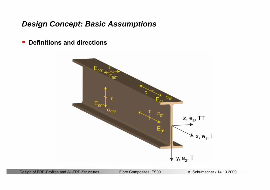
Design of FRP-Profiles and All-FRP-Structures Fibre Composites FS09 A Schumacher 14102009
Design Concept Basic Assumptions
Definitions and directions
Design of FRP-Profiles and All-FRP-Structures Fibre Composites FS09 A Schumacher 14102009
Design Concept
Codes
Every manufacturer has its own profile design rarr No European Design Code is available (only EN13706 about testing and notation)
There exists European guidelines EUROCOMP 1996 Design CodeEUROCOMP 1996 Handbook
Fiberline Design Manual is based on Eurocomp 1996
Design concept (according to Eurocodes and Swisscodes)
Partial safety factors
Measured material parameters
Rules for bolted connections
Design of FRP-Profiles and All-FRP-Structures Fibre Composites FS09 A Schumacher 14102009
Design Concept
Concept of Limit State Design (According to Euro Codes and Swiss Codes)
Ultimate limit stress
Ed le Rd
Ed hellip Calculated stress (including load factors) hellip SIA260 261
Rd hellip Rated value of the resistance capability
where
Rk hellip the calculated resistance capability
kd mγ=
RR
Design of FRP-Profiles and All-FRP-Structures Fibre Composites FS09 A Schumacher 14102009
101020Production process
Operating temperature
111116Degree of postcuring
115115225Derivation of mat properties
FiberlineMinMaxDescriptionCoefficient
Design Concept
Reduction coefficient m m1 m2 m3 m4γ γ γ γ γ= sdot sdot sdot
m1γ
m2γ
m3γ
m4γ
mγ mγ
31312580
2510-20 +60
Long-term loadShort-term load
Operatingtemperature degC m4γ
Design of FRP-Profiles and All-FRP-Structures Fibre Composites FS09 A Schumacher 14102009
Design Concept
Serviceability limit states
Ed le Cd
Ed hellip the crucial action effect due to the load cases considered inthe investigated dimensioning situation Typically maximaldeflection response of the structure
Cd hellip corresponding serviceability limit SIA 261
Design of FRP-Profiles and All-FRP-Structures Fibre Composites FS09 A Schumacher 14102009
Design Concept Basic Assumptions
Material Properties stength values (Fiberline Profiles)
Design of FRP-Profiles and All-FRP-Structures Fibre Composites FS09 A Schumacher 14102009
Design Concept Basic Assumptions
Material Properties stiffness values (Fiberline Profiles)
Design of FRP-Profiles and All-FRP-Structures Fibre Composites FS09 A Schumacher 14102009
Design Concept Basic Assumptions
Typical data sheet of a profile (Fiberline I-Profile)
Design of FRP-Profiles and All-FRP-Structures Fibre Composites FS09 A Schumacher 14102009
Bending Beam
Design of FRP-Profiles and All-FRP-Structures Fibre Composites FS09 A Schumacher 14102009
Bending Beam Design of hellip
Calculate bending moments Md and shear forces Qd acting on the profile using the partial coefficient (SIA 260 261)
Ultimate limit state
Bending
Shear
Ak hellip relevant shear area
d max d max 0max
M MW Wy z b
mzy
fσ γ
⎛ ⎞⎜ ⎟⎜ ⎟⎜ ⎟⎜ ⎟⎝ ⎠
deg= + le
d maxmax
kyAy
m
Q fττ γ= le
Design of FRP-Profiles and All-FRP-Structures Fibre Composites FS09 A Schumacher 14102009
Bending Beam Design of hellip
Serviceability limit state
Deflection limit
hellip typically selected between 200 and 400given by SIA 261 or the building owner
hellip calculated including shear deformations
Vibrations
Light-weighted and lsquosoftrsquo structures are susceptible to vibrations (traffic wind the movement of people hellip)
max 1wL αlt
α
maxw
Design of FRP-Profiles and All-FRP-Structures Fibre Composites FS09 A Schumacher 14102009
Bending Beam Timoshenko Theory
Pultruded profiles have a low shear modulus rarr shear deformation must be taken into account
Several bending theories have been published for beams
Euler-Bernoulli theory (1702)
Timoshenko theory (1968)
Higher order beam theory
A simply supported beam with a symmetric cross-section is discussed
Design of FRP-Profiles and All-FRP-Structures Fibre Composites FS09 A Schumacher 14102009
Bending Beam Timoshenko Theory
Cross-sections planeand perpendicular
1 degree of freedom
w
Cross-sections plane butNOT perpendicular
2 degrees of freedom
w and ψ
Cross-sections do NOTremain plane
3+ degrees of freedom
w ψ and hellip
Design of FRP-Profiles and All-FRP-Structures Fibre Composites FS09 A Schumacher 14102009
Bending Beam Euler vs Timoshenko Theory
Kinematic relationships
( )( )
( )
2 0
x x
y
xx xx
yxxy
u y w xu w x
u y w xxuu
y x
ε
ε
=minus sdot=
part= =minus sdotpartpartpart= + =
part part
( )( )
( )
2 ( ) ( )
x
y
xx x
yxxy x
u y xu w x
u y xxuu x w xy x
ψ
ε ψ
ε ψ
=minus sdot=
part= =minus sdotpartpartpart= + =minus +
part part
Hookrsquos law
0degE and G 2x x xy xyσ ε τ ε= sdot = sdot
z0deg E Iz x xxQS
M y dydz wσ= minus sdot sdot = sdot sdotintint
( )
z0deg E I
z x xQS
y xQS
M y dydz
Q dydz w GA
σ ψ
κ τ ψ κ
= minus sdot sdot = sdot
= sdot = minus sdot sdot
intint
intint
Design of FRP-Profiles and All-FRP-Structures Fibre Composites FS09 A Schumacher 14102009
Bending Beam Euler vs Timoshenko Theory
Equilibrium
Solution for the simply supported beam (distributed load)
In a first approximation the deflections are calculated by direct integration of
z0deg
( ) E IxxM xw = sdot
( )( )z0deg
( ) E I 0x
x
xx x
xx x
q x w GAw GA
QM Q
ψ κψ ψ κ
minus minus sdot sdot
sdot + minus sdot sdot
=minus =
= =minus
Equilibrium on an infinitesimal beam element
Coupled second order differential equation
21 1( ) (0) 0 and ( ) 02 2
M x qLx qx w w L= minus = =
( )3 2 3
0deg z
( ) 224 E Iqxw x L Lx x= sdot minus +sdot sdot
2
0deg z
1 1 1E I 2 2xxw qLx qx⎛ ⎞= minus⎜ ⎟sdot ⎝ ⎠
(0) 0 and ( ) 0(0) 0 (0) 0 and ( ) 0 ( ) 0 x x
w w LM M L Lψ ψ
= == rarr = = rarr =
Functions4 3 2
1 2 3 4 53 2
1 2 3 4
( )
( )
w x A x A x A x A x A
x B x B x B x Bψ
= + + + +
= + + +
Design of FRP-Profiles and All-FRP-Structures Fibre Composites FS09 A Schumacher 14102009
Put in and solve for the coefficients rarr
Bending Beam Euler vs Timoshenko Theory
Use the boundary conditions and the second differential eq to calculate A1 ndash A5
( )0deg z E I 0xx xw GAψ ψ κsdot + minus sdot sdot =
1 01 1 3 3
2 02 2 4 4
24 E I4 2GA
6 E I3 GA
z
z
AB A B A
AB A B A
κ
κ
deg
deg
sdot= minus = minus minus
sdotsdot
= minus = minus minussdot
( ) ( )( )2 2
0
( )2 GA 24 E Iz
qx L x L Lx xqx L xw x
κ deg
minus + minusminus= +
sdot sdot sdot
Deflection at midspan
4
0
52 384 E Iz
qLLw⎛ ⎞⎜ ⎟⎝ ⎠
deg
sdot= sdot4 2
0
52 384 E I 8 GAz
qL q LLw κ⎛ ⎞ +⎜ ⎟⎝ ⎠
deg
sdot sdot= sdot sdot sdot
Design of FRP-Profiles and All-FRP-Structures Fibre Composites FS09 A Schumacher 14102009
General expression for the total beam deflection as a sum of the deflection due to bending and shear
GAxf
IExfxwz sdot+=
deg κ)()()( 2
0
1
Cantilever beam
Simply supported
Concentrated load (P)
Uniformly distr load (q)
Concentrated load (P)
Uniformly distr load (q)
Beam )( max1 wf
3845 4qLsdot
48
3PL
8
4qL
3
3PL
)( max1 wf
8
2qL
4PL
2
2qL
PL
)( maxwx
2L
2L
L
L
Bending Beam Euler vs Timoshenko Theory
Design of FRP-Profiles and All-FRP-Structures Fibre Composites FS09 A Schumacher 14102009
Bending Beam Euler vs Timoshenko Theory
Example influence of the shear deformation
Profile 300 x 150 mm I-beam
Load uniformly distributed
General rule of thumbfor GFRP beams withspandepth gt 25 sheardeformation can beignored
Design of FRP-Profiles and All-FRP-Structures Fibre Composites FS09 A Schumacher 14102009
Bending Beam Example
Choose an appropriate Profile for the following specifications
1 Deflections and loading
=
=
==
1300 rarr wmax=001 mwmaxL
10 kNmqdser
13 kNmqduls
30 mL
max
4 2
0
5384 E I 8 GA
d ser d serz
q L q Lw κ+
deg
sdot sdot= sdot sdot sdot
2
maxz8 2 I
d ulsq L hσ sdot= sdot
maxky
12 Ad ulsq L
τ sdot=
Design of FRP-Profiles and All-FRP-Structures Fibre Composites FS09 A Schumacher 14102009
Bending Beam Example
2 Find a profile with sufficient bending stiffness
Shear deformations are neglected in a first step
rarr from specification table choose I 240x120x12 rarr
3 Check the bending and shear stresses
6 24
0 max
1054 10 Nm5
E I 384d ser
zq Lwdeg = sdot
sdotsdotge
6 20 1369 10 NmE Izdeg = sdot
2
maxz
358 MPa8 2 Id ulsq L hσ sdot= =sdot
max
ky
1 71 MPa2 Ad ulsq L
τ sdot= =
0 185 MPab df degle =
20 MPadfτle =
Design of FRP-Profiles and All-FRP-Structures Fibre Composites FS09 A Schumacher 14102009
Bending Beam Example
m10398384
5 32
0
4
maxminus
deg
sdot=sdotsdotsdot
+sdot
sdot=
GALq
IELq
w serd
z
serd
κ
4 Check deflection (including shear deformation)
5 Remarks
The design of GFRP-profiles is mostly driven by serviceability criteria
Start the design iteration procedure using the maximal deflection criterion
max 001 mwle =
m10198384
5 32
0
4
maxminus
deg
sdot=sdot
sdot+
sdotsdot
=web
serd
z
serd
GALq
IELq
w
(77 mm) (16 mm)
Design of FRP-Profiles and All-FRP-Structures Fibre Composites FS09 A Schumacher 14102009
Bending Beam Stability problems
Lateral-torsional bucklingFlange (compressive) displace laterally to the transverse load direction
Torsional stiffness is too low (especially for open section profiles)
Theoretical calculations or design measuresrarr see eg LP Kollaacuter 2003
Mechanics of composite structuresExample
Compressive flanges are kept in place by connection to the bridge deck
Design of FRP-Profiles and All-FRP-Structures Fibre Composites FS09 A Schumacher 14102009
Bending Beam Stability problems
Flange (compressive) displaces in the direction of the transverse load
Low bending stiffness perpendicular to the pultrusion direction
Weak fiber mats
Local buckling of walls due to in-plane compression
Local buckling of walls due to in-plane shear
Web crushing and web buckling in transverse direction
Design of FRP-Profiles and All-FRP-Structures Fibre Composites FS09 A Schumacher 14102009
Axial Members
Design of FRP-Profiles and All-FRP-Structures Fibre Composites FS09 A Schumacher 14102009
Axial Members Tension
Ultimate limit state under axial tension Nd
Serviceability limit state
Remark The critical aspect of axial members in tension are neither the serviceability nor the ultimate limit state Critical is the load transfer to the GFRP profile
0NdA
tm
fγ
degle
0deg
N LE Axδ sdot= sdot
Design of FRP-Profiles and All-FRP-Structures Fibre Composites FS09 A Schumacher 14102009
Axial Members Compression
Ultimate limit state under axial compression Nd
hellip maximal compressive load
hellip Euler load
hellip Buckling length for columns
hellip coefficient for Youngrsquos modulus = 13
cc
Euler
FNd F1 N
le+
c0degC
A fF
mγsdot
=
20
Euler 2
Nm E k
E IL
πγ
degsdot sdot=
sdot
kL
m Eγ
Design of FRP-Profiles and All-FRP-Structures Fibre Composites FS09 A Schumacher 14102009
Axial Members Compression
The influence of shear deformation should be considered but in the most cases the influence will be small (less than 5)
Local buckling should be considered for short columns
For more information on the various buckling modes and effects rarr see LP Kollaacuter 2003 Mechanics of composite structures
Global buckling Local buckling
Design of FRP-Profiles and All-FRP-Structures Fibre Composites FS09 A Schumacher 14102009
Connections
Design of FRP-Profiles and All-FRP-Structures Fibre Composites FS09 A Schumacher 14102009
Connections Introduction
Design of FRP-Profiles and All-FRP-Structures Fibre Composites FS09 A Schumacher 14102009
Connections Introduction
(from Eurocomp Design Code 1996)
Design of FRP-Profiles and All-FRP-Structures Fibre Composites FS09 A Schumacher 14102009
Connections Bolted joints
Bolts = Stress concentration in the profile and the bolt
It is necessary to ensure that the bolts and the profilecan withstand this concentrated local stress compression
It is necessary to ensure that the region surroundinga group of bolts will not be torn out of the profile
Basic failure modesin bolted shearconnections
bolt shear failure
Design of FRP-Profiles and All-FRP-Structures Fibre Composites FS09 A Schumacher 14102009
Connections Bolted joints
The design procedure is comparable to the one for steel connections but since there exist no standard GFRP material rarr each manufacturer has its own design rules for bolted joints
IMPORTANT REMARKS
The direction of pultrusion and the direction of the force is RELEVANT(anisotropic material)
Use stainless or galvanised steel
Do not cut threads in the composite material
Use screws with shafts
Design of FRP-Profiles and All-FRP-Structures Fibre Composites FS09 A Schumacher 14102009
Calculation of load bearing capacity of bolts
Shear in longitudinal direction (0deg)
Shear in transverse direction (90deg)
Tensile force
Minimum distances
Connections Bolted joints (Fiberline recommendations)
Design of FRP-Profiles and All-FRP-Structures Fibre Composites FS09 A Schumacher 14102009
Joint capacity tables available for shear and tension
m
150 MPa( 13)B d
d tP γsdot sdot=
=
Shear in longitudinal direction 0deg
m
70 MPa( 13)B d
d tP γsdot sdot=
=
Shear in transverse direction 90deg
Connections Bolted joints (Fiberline recommendations)
Design of FRP-Profiles and All-FRP-Structures Fibre Composites FS09 A Schumacher 14102009
Bolted connection in shear eg shear in longitudinal direction
Connections Bolted joints (Fiberline recommendations)
γmPBolt le dt720 MPaγmPBolt le dt240 MPa
γmPBolt le dt240 MPa γmPBolt le dt240 MPaγmPBolt le dt150 MPa
Design of FRP-Profiles and All-FRP-Structures Fibre Composites FS09 A Schumacher 14102009
Bolted connections in tension
Static conditions
Bolt Tearing of bolt in threaded cross-section
Laminate Shear fracture at rim of washer
Geometry and strength
Diameter of washer2d
Tensile strength of bolt hellipfyk
Shear strength of laminatehellipfτ
Thickness of laminatet
Stress area of the boltAs
Diameter of the boltd
s ykd m
A fP γ
sdotle
2d m
d t fP τπγ
sdot sdot sdot sdotle
Connections Bolted joints (Fiberline recommendations)
Design of FRP-Profiles and All-FRP-Structures Fibre Composites FS09 A Schumacher 14102009
Connections Bonded joints
Using an adhesive agent for joining profiles can have advantages
Easy to use easy to make aesthetic joints
Typically more rigid than bolted joints
Glued joints subjected to dynamic loads are good
But be careful hellipAdhesive agents have properties that depend on time temperature humidity hellip
Failure in glued joints takes place suddenly (brittle behaviour)
The load-bearing capacity is not proportional to the area which is glued
The design of bonded joints may be based onAnalytical models for plate-to-plate connections (see Eurocomp 1996 Design Code)
Design guidelines supplemented by testing
Finite element analysis
Design of FRP-Profiles and All-FRP-Structures Fibre Composites FS09 A Schumacher 14102009
Connections Bonded joints
A bonded joint has the following three primary failure modes
adhesive failure
cohesive failure of adhesive
cohesive failure of adherend
The design of any bonded joint shall satisfy the following conditions
allowable shear stress in the adhesive is not exceeded
allowable tensile (peel) stress in the adhesive is not exceeded
allowable through-thickness tensile stress of the adhesive is not exceeded
allowable in-plane shear stress of the adherend should not be exceeded
The calculation of the stresses has to be done very carefully Often calculations are supplemented by testing
Design of FRP-Profiles and All-FRP-Structures Fibre Composites FS09 A Schumacher 14102009
Connections Bonded joints
Different types of bonded joint configurations
Research on bonded joints for structuralapplications
Design of FRP-Profiles and All-FRP-Structures Fibre Composites FS09 A Schumacher 14102009
Connections Other joints
Brackets for assembly (Fiberline)
Custom pultruded connections
Design of FRP-Profiles and All-FRP-Structures Fibre Composites FS09 A Schumacher 14102009
GFRP Some final remarks
Perpendicular to the direction of pultrusion the material is WEAK and SOFTrarr avoid such loadings if possible
In order to use pultruded GFRP-profiles economically the design must be done in a clever way eg for bridges the railings should be used as part of the load-bearing structure
GFRP structures are very light rarr vibration problems may occur

Design of FRP-Profiles and All-FRP-Structures Fibre Composites FS09 A Schumacher 14102009
Design Concept
Codes
Every manufacturer has its own profile design rarr No European Design Code is available (only EN13706 about testing and notation)
There exists European guidelines EUROCOMP 1996 Design CodeEUROCOMP 1996 Handbook
Fiberline Design Manual is based on Eurocomp 1996
Design concept (according to Eurocodes and Swisscodes)
Partial safety factors
Measured material parameters
Rules for bolted connections
Design of FRP-Profiles and All-FRP-Structures Fibre Composites FS09 A Schumacher 14102009
Design Concept
Concept of Limit State Design (According to Euro Codes and Swiss Codes)
Ultimate limit stress
Ed le Rd
Ed hellip Calculated stress (including load factors) hellip SIA260 261
Rd hellip Rated value of the resistance capability
where
Rk hellip the calculated resistance capability
kd mγ=
RR
Design of FRP-Profiles and All-FRP-Structures Fibre Composites FS09 A Schumacher 14102009
101020Production process
Operating temperature
111116Degree of postcuring
115115225Derivation of mat properties
FiberlineMinMaxDescriptionCoefficient
Design Concept
Reduction coefficient m m1 m2 m3 m4γ γ γ γ γ= sdot sdot sdot
m1γ
m2γ
m3γ
m4γ
mγ mγ
31312580
2510-20 +60
Long-term loadShort-term load
Operatingtemperature degC m4γ
Design of FRP-Profiles and All-FRP-Structures Fibre Composites FS09 A Schumacher 14102009
Design Concept
Serviceability limit states
Ed le Cd
Ed hellip the crucial action effect due to the load cases considered inthe investigated dimensioning situation Typically maximaldeflection response of the structure
Cd hellip corresponding serviceability limit SIA 261
Design of FRP-Profiles and All-FRP-Structures Fibre Composites FS09 A Schumacher 14102009
Design Concept Basic Assumptions
Material Properties stength values (Fiberline Profiles)
Design of FRP-Profiles and All-FRP-Structures Fibre Composites FS09 A Schumacher 14102009
Design Concept Basic Assumptions
Material Properties stiffness values (Fiberline Profiles)
Design of FRP-Profiles and All-FRP-Structures Fibre Composites FS09 A Schumacher 14102009
Design Concept Basic Assumptions
Typical data sheet of a profile (Fiberline I-Profile)
Design of FRP-Profiles and All-FRP-Structures Fibre Composites FS09 A Schumacher 14102009
Bending Beam
Design of FRP-Profiles and All-FRP-Structures Fibre Composites FS09 A Schumacher 14102009
Bending Beam Design of hellip
Calculate bending moments Md and shear forces Qd acting on the profile using the partial coefficient (SIA 260 261)
Ultimate limit state
Bending
Shear
Ak hellip relevant shear area
d max d max 0max
M MW Wy z b
mzy
fσ γ
⎛ ⎞⎜ ⎟⎜ ⎟⎜ ⎟⎜ ⎟⎝ ⎠
deg= + le
d maxmax
kyAy
m
Q fττ γ= le
Design of FRP-Profiles and All-FRP-Structures Fibre Composites FS09 A Schumacher 14102009
Bending Beam Design of hellip
Serviceability limit state
Deflection limit
hellip typically selected between 200 and 400given by SIA 261 or the building owner
hellip calculated including shear deformations
Vibrations
Light-weighted and lsquosoftrsquo structures are susceptible to vibrations (traffic wind the movement of people hellip)
max 1wL αlt
α
maxw
Design of FRP-Profiles and All-FRP-Structures Fibre Composites FS09 A Schumacher 14102009
Bending Beam Timoshenko Theory
Pultruded profiles have a low shear modulus rarr shear deformation must be taken into account
Several bending theories have been published for beams
Euler-Bernoulli theory (1702)
Timoshenko theory (1968)
Higher order beam theory
A simply supported beam with a symmetric cross-section is discussed
Design of FRP-Profiles and All-FRP-Structures Fibre Composites FS09 A Schumacher 14102009
Bending Beam Timoshenko Theory
Cross-sections planeand perpendicular
1 degree of freedom
w
Cross-sections plane butNOT perpendicular
2 degrees of freedom
w and ψ
Cross-sections do NOTremain plane
3+ degrees of freedom
w ψ and hellip
Design of FRP-Profiles and All-FRP-Structures Fibre Composites FS09 A Schumacher 14102009
Bending Beam Euler vs Timoshenko Theory
Kinematic relationships
( )( )
( )
2 0
x x
y
xx xx
yxxy
u y w xu w x
u y w xxuu
y x
ε
ε
=minus sdot=
part= =minus sdotpartpartpart= + =
part part
( )( )
( )
2 ( ) ( )
x
y
xx x
yxxy x
u y xu w x
u y xxuu x w xy x
ψ
ε ψ
ε ψ
=minus sdot=
part= =minus sdotpartpartpart= + =minus +
part part
Hookrsquos law
0degE and G 2x x xy xyσ ε τ ε= sdot = sdot
z0deg E Iz x xxQS
M y dydz wσ= minus sdot sdot = sdot sdotintint
( )
z0deg E I
z x xQS
y xQS
M y dydz
Q dydz w GA
σ ψ
κ τ ψ κ
= minus sdot sdot = sdot
= sdot = minus sdot sdot
intint
intint
Design of FRP-Profiles and All-FRP-Structures Fibre Composites FS09 A Schumacher 14102009
Bending Beam Euler vs Timoshenko Theory
Equilibrium
Solution for the simply supported beam (distributed load)
In a first approximation the deflections are calculated by direct integration of
z0deg
( ) E IxxM xw = sdot
( )( )z0deg
( ) E I 0x
x
xx x
xx x
q x w GAw GA
QM Q
ψ κψ ψ κ
minus minus sdot sdot
sdot + minus sdot sdot
=minus =
= =minus
Equilibrium on an infinitesimal beam element
Coupled second order differential equation
21 1( ) (0) 0 and ( ) 02 2
M x qLx qx w w L= minus = =
( )3 2 3
0deg z
( ) 224 E Iqxw x L Lx x= sdot minus +sdot sdot
2
0deg z
1 1 1E I 2 2xxw qLx qx⎛ ⎞= minus⎜ ⎟sdot ⎝ ⎠
(0) 0 and ( ) 0(0) 0 (0) 0 and ( ) 0 ( ) 0 x x
w w LM M L Lψ ψ
= == rarr = = rarr =
Functions4 3 2
1 2 3 4 53 2
1 2 3 4
( )
( )
w x A x A x A x A x A
x B x B x B x Bψ
= + + + +
= + + +
Design of FRP-Profiles and All-FRP-Structures Fibre Composites FS09 A Schumacher 14102009
Put in and solve for the coefficients rarr
Bending Beam Euler vs Timoshenko Theory
Use the boundary conditions and the second differential eq to calculate A1 ndash A5
( )0deg z E I 0xx xw GAψ ψ κsdot + minus sdot sdot =
1 01 1 3 3
2 02 2 4 4
24 E I4 2GA
6 E I3 GA
z
z
AB A B A
AB A B A
κ
κ
deg
deg
sdot= minus = minus minus
sdotsdot
= minus = minus minussdot
( ) ( )( )2 2
0
( )2 GA 24 E Iz
qx L x L Lx xqx L xw x
κ deg
minus + minusminus= +
sdot sdot sdot
Deflection at midspan
4
0
52 384 E Iz
qLLw⎛ ⎞⎜ ⎟⎝ ⎠
deg
sdot= sdot4 2
0
52 384 E I 8 GAz
qL q LLw κ⎛ ⎞ +⎜ ⎟⎝ ⎠
deg
sdot sdot= sdot sdot sdot
Design of FRP-Profiles and All-FRP-Structures Fibre Composites FS09 A Schumacher 14102009
General expression for the total beam deflection as a sum of the deflection due to bending and shear
GAxf
IExfxwz sdot+=
deg κ)()()( 2
0
1
Cantilever beam
Simply supported
Concentrated load (P)
Uniformly distr load (q)
Concentrated load (P)
Uniformly distr load (q)
Beam )( max1 wf
3845 4qLsdot
48
3PL
8
4qL
3
3PL
)( max1 wf
8
2qL
4PL
2
2qL
PL
)( maxwx
2L
2L
L
L
Bending Beam Euler vs Timoshenko Theory
Design of FRP-Profiles and All-FRP-Structures Fibre Composites FS09 A Schumacher 14102009
Bending Beam Euler vs Timoshenko Theory
Example influence of the shear deformation
Profile 300 x 150 mm I-beam
Load uniformly distributed
General rule of thumbfor GFRP beams withspandepth gt 25 sheardeformation can beignored
Design of FRP-Profiles and All-FRP-Structures Fibre Composites FS09 A Schumacher 14102009
Bending Beam Example
Choose an appropriate Profile for the following specifications
1 Deflections and loading
=
=
==
1300 rarr wmax=001 mwmaxL
10 kNmqdser
13 kNmqduls
30 mL
max
4 2
0
5384 E I 8 GA
d ser d serz
q L q Lw κ+
deg
sdot sdot= sdot sdot sdot
2
maxz8 2 I
d ulsq L hσ sdot= sdot
maxky
12 Ad ulsq L
τ sdot=
Design of FRP-Profiles and All-FRP-Structures Fibre Composites FS09 A Schumacher 14102009
Bending Beam Example
2 Find a profile with sufficient bending stiffness
Shear deformations are neglected in a first step
rarr from specification table choose I 240x120x12 rarr
3 Check the bending and shear stresses
6 24
0 max
1054 10 Nm5
E I 384d ser
zq Lwdeg = sdot
sdotsdotge
6 20 1369 10 NmE Izdeg = sdot
2
maxz
358 MPa8 2 Id ulsq L hσ sdot= =sdot
max
ky
1 71 MPa2 Ad ulsq L
τ sdot= =
0 185 MPab df degle =
20 MPadfτle =
Design of FRP-Profiles and All-FRP-Structures Fibre Composites FS09 A Schumacher 14102009
Bending Beam Example
m10398384
5 32
0
4
maxminus
deg
sdot=sdotsdotsdot
+sdot
sdot=
GALq
IELq
w serd
z
serd
κ
4 Check deflection (including shear deformation)
5 Remarks
The design of GFRP-profiles is mostly driven by serviceability criteria
Start the design iteration procedure using the maximal deflection criterion
max 001 mwle =
m10198384
5 32
0
4
maxminus
deg
sdot=sdot
sdot+
sdotsdot
=web
serd
z
serd
GALq
IELq
w
(77 mm) (16 mm)
Design of FRP-Profiles and All-FRP-Structures Fibre Composites FS09 A Schumacher 14102009
Bending Beam Stability problems
Lateral-torsional bucklingFlange (compressive) displace laterally to the transverse load direction
Torsional stiffness is too low (especially for open section profiles)
Theoretical calculations or design measuresrarr see eg LP Kollaacuter 2003
Mechanics of composite structuresExample
Compressive flanges are kept in place by connection to the bridge deck
Design of FRP-Profiles and All-FRP-Structures Fibre Composites FS09 A Schumacher 14102009
Bending Beam Stability problems
Flange (compressive) displaces in the direction of the transverse load
Low bending stiffness perpendicular to the pultrusion direction
Weak fiber mats
Local buckling of walls due to in-plane compression
Local buckling of walls due to in-plane shear
Web crushing and web buckling in transverse direction
Design of FRP-Profiles and All-FRP-Structures Fibre Composites FS09 A Schumacher 14102009
Axial Members
Design of FRP-Profiles and All-FRP-Structures Fibre Composites FS09 A Schumacher 14102009
Axial Members Tension
Ultimate limit state under axial tension Nd
Serviceability limit state
Remark The critical aspect of axial members in tension are neither the serviceability nor the ultimate limit state Critical is the load transfer to the GFRP profile
0NdA
tm
fγ
degle
0deg
N LE Axδ sdot= sdot
Design of FRP-Profiles and All-FRP-Structures Fibre Composites FS09 A Schumacher 14102009
Axial Members Compression
Ultimate limit state under axial compression Nd
hellip maximal compressive load
hellip Euler load
hellip Buckling length for columns
hellip coefficient for Youngrsquos modulus = 13
cc
Euler
FNd F1 N
le+
c0degC
A fF
mγsdot
=
20
Euler 2
Nm E k
E IL
πγ
degsdot sdot=
sdot
kL
m Eγ
Design of FRP-Profiles and All-FRP-Structures Fibre Composites FS09 A Schumacher 14102009
Axial Members Compression
The influence of shear deformation should be considered but in the most cases the influence will be small (less than 5)
Local buckling should be considered for short columns
For more information on the various buckling modes and effects rarr see LP Kollaacuter 2003 Mechanics of composite structures
Global buckling Local buckling
Design of FRP-Profiles and All-FRP-Structures Fibre Composites FS09 A Schumacher 14102009
Connections
Design of FRP-Profiles and All-FRP-Structures Fibre Composites FS09 A Schumacher 14102009
Connections Introduction
Design of FRP-Profiles and All-FRP-Structures Fibre Composites FS09 A Schumacher 14102009
Connections Introduction
(from Eurocomp Design Code 1996)
Design of FRP-Profiles and All-FRP-Structures Fibre Composites FS09 A Schumacher 14102009
Connections Bolted joints
Bolts = Stress concentration in the profile and the bolt
It is necessary to ensure that the bolts and the profilecan withstand this concentrated local stress compression
It is necessary to ensure that the region surroundinga group of bolts will not be torn out of the profile
Basic failure modesin bolted shearconnections
bolt shear failure
Design of FRP-Profiles and All-FRP-Structures Fibre Composites FS09 A Schumacher 14102009
Connections Bolted joints
The design procedure is comparable to the one for steel connections but since there exist no standard GFRP material rarr each manufacturer has its own design rules for bolted joints
IMPORTANT REMARKS
The direction of pultrusion and the direction of the force is RELEVANT(anisotropic material)
Use stainless or galvanised steel
Do not cut threads in the composite material
Use screws with shafts
Design of FRP-Profiles and All-FRP-Structures Fibre Composites FS09 A Schumacher 14102009
Calculation of load bearing capacity of bolts
Shear in longitudinal direction (0deg)
Shear in transverse direction (90deg)
Tensile force
Minimum distances
Connections Bolted joints (Fiberline recommendations)
Design of FRP-Profiles and All-FRP-Structures Fibre Composites FS09 A Schumacher 14102009
Joint capacity tables available for shear and tension
m
150 MPa( 13)B d
d tP γsdot sdot=
=
Shear in longitudinal direction 0deg
m
70 MPa( 13)B d
d tP γsdot sdot=
=
Shear in transverse direction 90deg
Connections Bolted joints (Fiberline recommendations)
Design of FRP-Profiles and All-FRP-Structures Fibre Composites FS09 A Schumacher 14102009
Bolted connection in shear eg shear in longitudinal direction
Connections Bolted joints (Fiberline recommendations)
γmPBolt le dt720 MPaγmPBolt le dt240 MPa
γmPBolt le dt240 MPa γmPBolt le dt240 MPaγmPBolt le dt150 MPa
Design of FRP-Profiles and All-FRP-Structures Fibre Composites FS09 A Schumacher 14102009
Bolted connections in tension
Static conditions
Bolt Tearing of bolt in threaded cross-section
Laminate Shear fracture at rim of washer
Geometry and strength
Diameter of washer2d
Tensile strength of bolt hellipfyk
Shear strength of laminatehellipfτ
Thickness of laminatet
Stress area of the boltAs
Diameter of the boltd
s ykd m
A fP γ
sdotle
2d m
d t fP τπγ
sdot sdot sdot sdotle
Connections Bolted joints (Fiberline recommendations)
Design of FRP-Profiles and All-FRP-Structures Fibre Composites FS09 A Schumacher 14102009
Connections Bonded joints
Using an adhesive agent for joining profiles can have advantages
Easy to use easy to make aesthetic joints
Typically more rigid than bolted joints
Glued joints subjected to dynamic loads are good
But be careful hellipAdhesive agents have properties that depend on time temperature humidity hellip
Failure in glued joints takes place suddenly (brittle behaviour)
The load-bearing capacity is not proportional to the area which is glued
The design of bonded joints may be based onAnalytical models for plate-to-plate connections (see Eurocomp 1996 Design Code)
Design guidelines supplemented by testing
Finite element analysis
Design of FRP-Profiles and All-FRP-Structures Fibre Composites FS09 A Schumacher 14102009
Connections Bonded joints
A bonded joint has the following three primary failure modes
adhesive failure
cohesive failure of adhesive
cohesive failure of adherend
The design of any bonded joint shall satisfy the following conditions
allowable shear stress in the adhesive is not exceeded
allowable tensile (peel) stress in the adhesive is not exceeded
allowable through-thickness tensile stress of the adhesive is not exceeded
allowable in-plane shear stress of the adherend should not be exceeded
The calculation of the stresses has to be done very carefully Often calculations are supplemented by testing
Design of FRP-Profiles and All-FRP-Structures Fibre Composites FS09 A Schumacher 14102009
Connections Bonded joints
Different types of bonded joint configurations
Research on bonded joints for structuralapplications
Design of FRP-Profiles and All-FRP-Structures Fibre Composites FS09 A Schumacher 14102009
Connections Other joints
Brackets for assembly (Fiberline)
Custom pultruded connections
Design of FRP-Profiles and All-FRP-Structures Fibre Composites FS09 A Schumacher 14102009
GFRP Some final remarks
Perpendicular to the direction of pultrusion the material is WEAK and SOFTrarr avoid such loadings if possible
In order to use pultruded GFRP-profiles economically the design must be done in a clever way eg for bridges the railings should be used as part of the load-bearing structure
GFRP structures are very light rarr vibration problems may occur
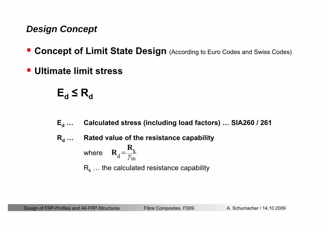
Design of FRP-Profiles and All-FRP-Structures Fibre Composites FS09 A Schumacher 14102009
Design Concept
Concept of Limit State Design (According to Euro Codes and Swiss Codes)
Ultimate limit stress
Ed le Rd
Ed hellip Calculated stress (including load factors) hellip SIA260 261
Rd hellip Rated value of the resistance capability
where
Rk hellip the calculated resistance capability
kd mγ=
RR
Design of FRP-Profiles and All-FRP-Structures Fibre Composites FS09 A Schumacher 14102009
101020Production process
Operating temperature
111116Degree of postcuring
115115225Derivation of mat properties
FiberlineMinMaxDescriptionCoefficient
Design Concept
Reduction coefficient m m1 m2 m3 m4γ γ γ γ γ= sdot sdot sdot
m1γ
m2γ
m3γ
m4γ
mγ mγ
31312580
2510-20 +60
Long-term loadShort-term load
Operatingtemperature degC m4γ
Design of FRP-Profiles and All-FRP-Structures Fibre Composites FS09 A Schumacher 14102009
Design Concept
Serviceability limit states
Ed le Cd
Ed hellip the crucial action effect due to the load cases considered inthe investigated dimensioning situation Typically maximaldeflection response of the structure
Cd hellip corresponding serviceability limit SIA 261
Design of FRP-Profiles and All-FRP-Structures Fibre Composites FS09 A Schumacher 14102009
Design Concept Basic Assumptions
Material Properties stength values (Fiberline Profiles)
Design of FRP-Profiles and All-FRP-Structures Fibre Composites FS09 A Schumacher 14102009
Design Concept Basic Assumptions
Material Properties stiffness values (Fiberline Profiles)
Design of FRP-Profiles and All-FRP-Structures Fibre Composites FS09 A Schumacher 14102009
Design Concept Basic Assumptions
Typical data sheet of a profile (Fiberline I-Profile)
Design of FRP-Profiles and All-FRP-Structures Fibre Composites FS09 A Schumacher 14102009
Bending Beam
Design of FRP-Profiles and All-FRP-Structures Fibre Composites FS09 A Schumacher 14102009
Bending Beam Design of hellip
Calculate bending moments Md and shear forces Qd acting on the profile using the partial coefficient (SIA 260 261)
Ultimate limit state
Bending
Shear
Ak hellip relevant shear area
d max d max 0max
M MW Wy z b
mzy
fσ γ
⎛ ⎞⎜ ⎟⎜ ⎟⎜ ⎟⎜ ⎟⎝ ⎠
deg= + le
d maxmax
kyAy
m
Q fττ γ= le
Design of FRP-Profiles and All-FRP-Structures Fibre Composites FS09 A Schumacher 14102009
Bending Beam Design of hellip
Serviceability limit state
Deflection limit
hellip typically selected between 200 and 400given by SIA 261 or the building owner
hellip calculated including shear deformations
Vibrations
Light-weighted and lsquosoftrsquo structures are susceptible to vibrations (traffic wind the movement of people hellip)
max 1wL αlt
α
maxw
Design of FRP-Profiles and All-FRP-Structures Fibre Composites FS09 A Schumacher 14102009
Bending Beam Timoshenko Theory
Pultruded profiles have a low shear modulus rarr shear deformation must be taken into account
Several bending theories have been published for beams
Euler-Bernoulli theory (1702)
Timoshenko theory (1968)
Higher order beam theory
A simply supported beam with a symmetric cross-section is discussed
Design of FRP-Profiles and All-FRP-Structures Fibre Composites FS09 A Schumacher 14102009
Bending Beam Timoshenko Theory
Cross-sections planeand perpendicular
1 degree of freedom
w
Cross-sections plane butNOT perpendicular
2 degrees of freedom
w and ψ
Cross-sections do NOTremain plane
3+ degrees of freedom
w ψ and hellip
Design of FRP-Profiles and All-FRP-Structures Fibre Composites FS09 A Schumacher 14102009
Bending Beam Euler vs Timoshenko Theory
Kinematic relationships
( )( )
( )
2 0
x x
y
xx xx
yxxy
u y w xu w x
u y w xxuu
y x
ε
ε
=minus sdot=
part= =minus sdotpartpartpart= + =
part part
( )( )
( )
2 ( ) ( )
x
y
xx x
yxxy x
u y xu w x
u y xxuu x w xy x
ψ
ε ψ
ε ψ
=minus sdot=
part= =minus sdotpartpartpart= + =minus +
part part
Hookrsquos law
0degE and G 2x x xy xyσ ε τ ε= sdot = sdot
z0deg E Iz x xxQS
M y dydz wσ= minus sdot sdot = sdot sdotintint
( )
z0deg E I
z x xQS
y xQS
M y dydz
Q dydz w GA
σ ψ
κ τ ψ κ
= minus sdot sdot = sdot
= sdot = minus sdot sdot
intint
intint
Design of FRP-Profiles and All-FRP-Structures Fibre Composites FS09 A Schumacher 14102009
Bending Beam Euler vs Timoshenko Theory
Equilibrium
Solution for the simply supported beam (distributed load)
In a first approximation the deflections are calculated by direct integration of
z0deg
( ) E IxxM xw = sdot
( )( )z0deg
( ) E I 0x
x
xx x
xx x
q x w GAw GA
QM Q
ψ κψ ψ κ
minus minus sdot sdot
sdot + minus sdot sdot
=minus =
= =minus
Equilibrium on an infinitesimal beam element
Coupled second order differential equation
21 1( ) (0) 0 and ( ) 02 2
M x qLx qx w w L= minus = =
( )3 2 3
0deg z
( ) 224 E Iqxw x L Lx x= sdot minus +sdot sdot
2
0deg z
1 1 1E I 2 2xxw qLx qx⎛ ⎞= minus⎜ ⎟sdot ⎝ ⎠
(0) 0 and ( ) 0(0) 0 (0) 0 and ( ) 0 ( ) 0 x x
w w LM M L Lψ ψ
= == rarr = = rarr =
Functions4 3 2
1 2 3 4 53 2
1 2 3 4
( )
( )
w x A x A x A x A x A
x B x B x B x Bψ
= + + + +
= + + +
Design of FRP-Profiles and All-FRP-Structures Fibre Composites FS09 A Schumacher 14102009
Put in and solve for the coefficients rarr
Bending Beam Euler vs Timoshenko Theory
Use the boundary conditions and the second differential eq to calculate A1 ndash A5
( )0deg z E I 0xx xw GAψ ψ κsdot + minus sdot sdot =
1 01 1 3 3
2 02 2 4 4
24 E I4 2GA
6 E I3 GA
z
z
AB A B A
AB A B A
κ
κ
deg
deg
sdot= minus = minus minus
sdotsdot
= minus = minus minussdot
( ) ( )( )2 2
0
( )2 GA 24 E Iz
qx L x L Lx xqx L xw x
κ deg
minus + minusminus= +
sdot sdot sdot
Deflection at midspan
4
0
52 384 E Iz
qLLw⎛ ⎞⎜ ⎟⎝ ⎠
deg
sdot= sdot4 2
0
52 384 E I 8 GAz
qL q LLw κ⎛ ⎞ +⎜ ⎟⎝ ⎠
deg
sdot sdot= sdot sdot sdot
Design of FRP-Profiles and All-FRP-Structures Fibre Composites FS09 A Schumacher 14102009
General expression for the total beam deflection as a sum of the deflection due to bending and shear
GAxf
IExfxwz sdot+=
deg κ)()()( 2
0
1
Cantilever beam
Simply supported
Concentrated load (P)
Uniformly distr load (q)
Concentrated load (P)
Uniformly distr load (q)
Beam )( max1 wf
3845 4qLsdot
48
3PL
8
4qL
3
3PL
)( max1 wf
8
2qL
4PL
2
2qL
PL
)( maxwx
2L
2L
L
L
Bending Beam Euler vs Timoshenko Theory
Design of FRP-Profiles and All-FRP-Structures Fibre Composites FS09 A Schumacher 14102009
Bending Beam Euler vs Timoshenko Theory
Example influence of the shear deformation
Profile 300 x 150 mm I-beam
Load uniformly distributed
General rule of thumbfor GFRP beams withspandepth gt 25 sheardeformation can beignored
Design of FRP-Profiles and All-FRP-Structures Fibre Composites FS09 A Schumacher 14102009
Bending Beam Example
Choose an appropriate Profile for the following specifications
1 Deflections and loading
=
=
==
1300 rarr wmax=001 mwmaxL
10 kNmqdser
13 kNmqduls
30 mL
max
4 2
0
5384 E I 8 GA
d ser d serz
q L q Lw κ+
deg
sdot sdot= sdot sdot sdot
2
maxz8 2 I
d ulsq L hσ sdot= sdot
maxky
12 Ad ulsq L
τ sdot=
Design of FRP-Profiles and All-FRP-Structures Fibre Composites FS09 A Schumacher 14102009
Bending Beam Example
2 Find a profile with sufficient bending stiffness
Shear deformations are neglected in a first step
rarr from specification table choose I 240x120x12 rarr
3 Check the bending and shear stresses
6 24
0 max
1054 10 Nm5
E I 384d ser
zq Lwdeg = sdot
sdotsdotge
6 20 1369 10 NmE Izdeg = sdot
2
maxz
358 MPa8 2 Id ulsq L hσ sdot= =sdot
max
ky
1 71 MPa2 Ad ulsq L
τ sdot= =
0 185 MPab df degle =
20 MPadfτle =
Design of FRP-Profiles and All-FRP-Structures Fibre Composites FS09 A Schumacher 14102009
Bending Beam Example
m10398384
5 32
0
4
maxminus
deg
sdot=sdotsdotsdot
+sdot
sdot=
GALq
IELq
w serd
z
serd
κ
4 Check deflection (including shear deformation)
5 Remarks
The design of GFRP-profiles is mostly driven by serviceability criteria
Start the design iteration procedure using the maximal deflection criterion
max 001 mwle =
m10198384
5 32
0
4
maxminus
deg
sdot=sdot
sdot+
sdotsdot
=web
serd
z
serd
GALq
IELq
w
(77 mm) (16 mm)
Design of FRP-Profiles and All-FRP-Structures Fibre Composites FS09 A Schumacher 14102009
Bending Beam Stability problems
Lateral-torsional bucklingFlange (compressive) displace laterally to the transverse load direction
Torsional stiffness is too low (especially for open section profiles)
Theoretical calculations or design measuresrarr see eg LP Kollaacuter 2003
Mechanics of composite structuresExample
Compressive flanges are kept in place by connection to the bridge deck
Design of FRP-Profiles and All-FRP-Structures Fibre Composites FS09 A Schumacher 14102009
Bending Beam Stability problems
Flange (compressive) displaces in the direction of the transverse load
Low bending stiffness perpendicular to the pultrusion direction
Weak fiber mats
Local buckling of walls due to in-plane compression
Local buckling of walls due to in-plane shear
Web crushing and web buckling in transverse direction
Design of FRP-Profiles and All-FRP-Structures Fibre Composites FS09 A Schumacher 14102009
Axial Members
Design of FRP-Profiles and All-FRP-Structures Fibre Composites FS09 A Schumacher 14102009
Axial Members Tension
Ultimate limit state under axial tension Nd
Serviceability limit state
Remark The critical aspect of axial members in tension are neither the serviceability nor the ultimate limit state Critical is the load transfer to the GFRP profile
0NdA
tm
fγ
degle
0deg
N LE Axδ sdot= sdot
Design of FRP-Profiles and All-FRP-Structures Fibre Composites FS09 A Schumacher 14102009
Axial Members Compression
Ultimate limit state under axial compression Nd
hellip maximal compressive load
hellip Euler load
hellip Buckling length for columns
hellip coefficient for Youngrsquos modulus = 13
cc
Euler
FNd F1 N
le+
c0degC
A fF
mγsdot
=
20
Euler 2
Nm E k
E IL
πγ
degsdot sdot=
sdot
kL
m Eγ
Design of FRP-Profiles and All-FRP-Structures Fibre Composites FS09 A Schumacher 14102009
Axial Members Compression
The influence of shear deformation should be considered but in the most cases the influence will be small (less than 5)
Local buckling should be considered for short columns
For more information on the various buckling modes and effects rarr see LP Kollaacuter 2003 Mechanics of composite structures
Global buckling Local buckling
Design of FRP-Profiles and All-FRP-Structures Fibre Composites FS09 A Schumacher 14102009
Connections
Design of FRP-Profiles and All-FRP-Structures Fibre Composites FS09 A Schumacher 14102009
Connections Introduction
Design of FRP-Profiles and All-FRP-Structures Fibre Composites FS09 A Schumacher 14102009
Connections Introduction
(from Eurocomp Design Code 1996)
Design of FRP-Profiles and All-FRP-Structures Fibre Composites FS09 A Schumacher 14102009
Connections Bolted joints
Bolts = Stress concentration in the profile and the bolt
It is necessary to ensure that the bolts and the profilecan withstand this concentrated local stress compression
It is necessary to ensure that the region surroundinga group of bolts will not be torn out of the profile
Basic failure modesin bolted shearconnections
bolt shear failure
Design of FRP-Profiles and All-FRP-Structures Fibre Composites FS09 A Schumacher 14102009
Connections Bolted joints
The design procedure is comparable to the one for steel connections but since there exist no standard GFRP material rarr each manufacturer has its own design rules for bolted joints
IMPORTANT REMARKS
The direction of pultrusion and the direction of the force is RELEVANT(anisotropic material)
Use stainless or galvanised steel
Do not cut threads in the composite material
Use screws with shafts
Design of FRP-Profiles and All-FRP-Structures Fibre Composites FS09 A Schumacher 14102009
Calculation of load bearing capacity of bolts
Shear in longitudinal direction (0deg)
Shear in transverse direction (90deg)
Tensile force
Minimum distances
Connections Bolted joints (Fiberline recommendations)
Design of FRP-Profiles and All-FRP-Structures Fibre Composites FS09 A Schumacher 14102009
Joint capacity tables available for shear and tension
m
150 MPa( 13)B d
d tP γsdot sdot=
=
Shear in longitudinal direction 0deg
m
70 MPa( 13)B d
d tP γsdot sdot=
=
Shear in transverse direction 90deg
Connections Bolted joints (Fiberline recommendations)
Design of FRP-Profiles and All-FRP-Structures Fibre Composites FS09 A Schumacher 14102009
Bolted connection in shear eg shear in longitudinal direction
Connections Bolted joints (Fiberline recommendations)
γmPBolt le dt720 MPaγmPBolt le dt240 MPa
γmPBolt le dt240 MPa γmPBolt le dt240 MPaγmPBolt le dt150 MPa
Design of FRP-Profiles and All-FRP-Structures Fibre Composites FS09 A Schumacher 14102009
Bolted connections in tension
Static conditions
Bolt Tearing of bolt in threaded cross-section
Laminate Shear fracture at rim of washer
Geometry and strength
Diameter of washer2d
Tensile strength of bolt hellipfyk
Shear strength of laminatehellipfτ
Thickness of laminatet
Stress area of the boltAs
Diameter of the boltd
s ykd m
A fP γ
sdotle
2d m
d t fP τπγ
sdot sdot sdot sdotle
Connections Bolted joints (Fiberline recommendations)
Design of FRP-Profiles and All-FRP-Structures Fibre Composites FS09 A Schumacher 14102009
Connections Bonded joints
Using an adhesive agent for joining profiles can have advantages
Easy to use easy to make aesthetic joints
Typically more rigid than bolted joints
Glued joints subjected to dynamic loads are good
But be careful hellipAdhesive agents have properties that depend on time temperature humidity hellip
Failure in glued joints takes place suddenly (brittle behaviour)
The load-bearing capacity is not proportional to the area which is glued
The design of bonded joints may be based onAnalytical models for plate-to-plate connections (see Eurocomp 1996 Design Code)
Design guidelines supplemented by testing
Finite element analysis
Design of FRP-Profiles and All-FRP-Structures Fibre Composites FS09 A Schumacher 14102009
Connections Bonded joints
A bonded joint has the following three primary failure modes
adhesive failure
cohesive failure of adhesive
cohesive failure of adherend
The design of any bonded joint shall satisfy the following conditions
allowable shear stress in the adhesive is not exceeded
allowable tensile (peel) stress in the adhesive is not exceeded
allowable through-thickness tensile stress of the adhesive is not exceeded
allowable in-plane shear stress of the adherend should not be exceeded
The calculation of the stresses has to be done very carefully Often calculations are supplemented by testing
Design of FRP-Profiles and All-FRP-Structures Fibre Composites FS09 A Schumacher 14102009
Connections Bonded joints
Different types of bonded joint configurations
Research on bonded joints for structuralapplications
Design of FRP-Profiles and All-FRP-Structures Fibre Composites FS09 A Schumacher 14102009
Connections Other joints
Brackets for assembly (Fiberline)
Custom pultruded connections
Design of FRP-Profiles and All-FRP-Structures Fibre Composites FS09 A Schumacher 14102009
GFRP Some final remarks
Perpendicular to the direction of pultrusion the material is WEAK and SOFTrarr avoid such loadings if possible
In order to use pultruded GFRP-profiles economically the design must be done in a clever way eg for bridges the railings should be used as part of the load-bearing structure
GFRP structures are very light rarr vibration problems may occur
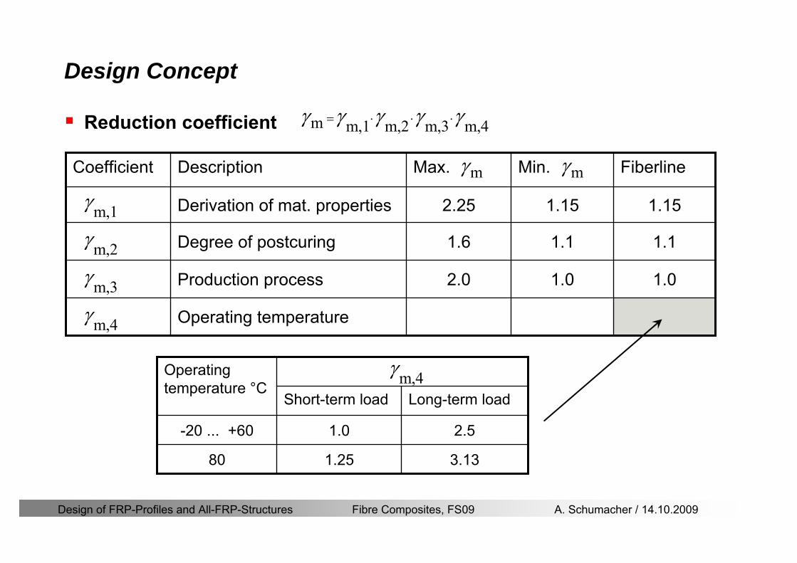
Design of FRP-Profiles and All-FRP-Structures Fibre Composites FS09 A Schumacher 14102009
101020Production process
Operating temperature
111116Degree of postcuring
115115225Derivation of mat properties
FiberlineMinMaxDescriptionCoefficient
Design Concept
Reduction coefficient m m1 m2 m3 m4γ γ γ γ γ= sdot sdot sdot
m1γ
m2γ
m3γ
m4γ
mγ mγ
31312580
2510-20 +60
Long-term loadShort-term load
Operatingtemperature degC m4γ
Design of FRP-Profiles and All-FRP-Structures Fibre Composites FS09 A Schumacher 14102009
Design Concept
Serviceability limit states
Ed le Cd
Ed hellip the crucial action effect due to the load cases considered inthe investigated dimensioning situation Typically maximaldeflection response of the structure
Cd hellip corresponding serviceability limit SIA 261
Design of FRP-Profiles and All-FRP-Structures Fibre Composites FS09 A Schumacher 14102009
Design Concept Basic Assumptions
Material Properties stength values (Fiberline Profiles)
Design of FRP-Profiles and All-FRP-Structures Fibre Composites FS09 A Schumacher 14102009
Design Concept Basic Assumptions
Material Properties stiffness values (Fiberline Profiles)
Design of FRP-Profiles and All-FRP-Structures Fibre Composites FS09 A Schumacher 14102009
Design Concept Basic Assumptions
Typical data sheet of a profile (Fiberline I-Profile)
Design of FRP-Profiles and All-FRP-Structures Fibre Composites FS09 A Schumacher 14102009
Bending Beam
Design of FRP-Profiles and All-FRP-Structures Fibre Composites FS09 A Schumacher 14102009
Bending Beam Design of hellip
Calculate bending moments Md and shear forces Qd acting on the profile using the partial coefficient (SIA 260 261)
Ultimate limit state
Bending
Shear
Ak hellip relevant shear area
d max d max 0max
M MW Wy z b
mzy
fσ γ
⎛ ⎞⎜ ⎟⎜ ⎟⎜ ⎟⎜ ⎟⎝ ⎠
deg= + le
d maxmax
kyAy
m
Q fττ γ= le
Design of FRP-Profiles and All-FRP-Structures Fibre Composites FS09 A Schumacher 14102009
Bending Beam Design of hellip
Serviceability limit state
Deflection limit
hellip typically selected between 200 and 400given by SIA 261 or the building owner
hellip calculated including shear deformations
Vibrations
Light-weighted and lsquosoftrsquo structures are susceptible to vibrations (traffic wind the movement of people hellip)
max 1wL αlt
α
maxw
Design of FRP-Profiles and All-FRP-Structures Fibre Composites FS09 A Schumacher 14102009
Bending Beam Timoshenko Theory
Pultruded profiles have a low shear modulus rarr shear deformation must be taken into account
Several bending theories have been published for beams
Euler-Bernoulli theory (1702)
Timoshenko theory (1968)
Higher order beam theory
A simply supported beam with a symmetric cross-section is discussed
Design of FRP-Profiles and All-FRP-Structures Fibre Composites FS09 A Schumacher 14102009
Bending Beam Timoshenko Theory
Cross-sections planeand perpendicular
1 degree of freedom
w
Cross-sections plane butNOT perpendicular
2 degrees of freedom
w and ψ
Cross-sections do NOTremain plane
3+ degrees of freedom
w ψ and hellip
Design of FRP-Profiles and All-FRP-Structures Fibre Composites FS09 A Schumacher 14102009
Bending Beam Euler vs Timoshenko Theory
Kinematic relationships
( )( )
( )
2 0
x x
y
xx xx
yxxy
u y w xu w x
u y w xxuu
y x
ε
ε
=minus sdot=
part= =minus sdotpartpartpart= + =
part part
( )( )
( )
2 ( ) ( )
x
y
xx x
yxxy x
u y xu w x
u y xxuu x w xy x
ψ
ε ψ
ε ψ
=minus sdot=
part= =minus sdotpartpartpart= + =minus +
part part
Hookrsquos law
0degE and G 2x x xy xyσ ε τ ε= sdot = sdot
z0deg E Iz x xxQS
M y dydz wσ= minus sdot sdot = sdot sdotintint
( )
z0deg E I
z x xQS
y xQS
M y dydz
Q dydz w GA
σ ψ
κ τ ψ κ
= minus sdot sdot = sdot
= sdot = minus sdot sdot
intint
intint
Design of FRP-Profiles and All-FRP-Structures Fibre Composites FS09 A Schumacher 14102009
Bending Beam Euler vs Timoshenko Theory
Equilibrium
Solution for the simply supported beam (distributed load)
In a first approximation the deflections are calculated by direct integration of
z0deg
( ) E IxxM xw = sdot
( )( )z0deg
( ) E I 0x
x
xx x
xx x
q x w GAw GA
QM Q
ψ κψ ψ κ
minus minus sdot sdot
sdot + minus sdot sdot
=minus =
= =minus
Equilibrium on an infinitesimal beam element
Coupled second order differential equation
21 1( ) (0) 0 and ( ) 02 2
M x qLx qx w w L= minus = =
( )3 2 3
0deg z
( ) 224 E Iqxw x L Lx x= sdot minus +sdot sdot
2
0deg z
1 1 1E I 2 2xxw qLx qx⎛ ⎞= minus⎜ ⎟sdot ⎝ ⎠
(0) 0 and ( ) 0(0) 0 (0) 0 and ( ) 0 ( ) 0 x x
w w LM M L Lψ ψ
= == rarr = = rarr =
Functions4 3 2
1 2 3 4 53 2
1 2 3 4
( )
( )
w x A x A x A x A x A
x B x B x B x Bψ
= + + + +
= + + +
Design of FRP-Profiles and All-FRP-Structures Fibre Composites FS09 A Schumacher 14102009
Put in and solve for the coefficients rarr
Bending Beam Euler vs Timoshenko Theory
Use the boundary conditions and the second differential eq to calculate A1 ndash A5
( )0deg z E I 0xx xw GAψ ψ κsdot + minus sdot sdot =
1 01 1 3 3
2 02 2 4 4
24 E I4 2GA
6 E I3 GA
z
z
AB A B A
AB A B A
κ
κ
deg
deg
sdot= minus = minus minus
sdotsdot
= minus = minus minussdot
( ) ( )( )2 2
0
( )2 GA 24 E Iz
qx L x L Lx xqx L xw x
κ deg
minus + minusminus= +
sdot sdot sdot
Deflection at midspan
4
0
52 384 E Iz
qLLw⎛ ⎞⎜ ⎟⎝ ⎠
deg
sdot= sdot4 2
0
52 384 E I 8 GAz
qL q LLw κ⎛ ⎞ +⎜ ⎟⎝ ⎠
deg
sdot sdot= sdot sdot sdot
Design of FRP-Profiles and All-FRP-Structures Fibre Composites FS09 A Schumacher 14102009
General expression for the total beam deflection as a sum of the deflection due to bending and shear
GAxf
IExfxwz sdot+=
deg κ)()()( 2
0
1
Cantilever beam
Simply supported
Concentrated load (P)
Uniformly distr load (q)
Concentrated load (P)
Uniformly distr load (q)
Beam )( max1 wf
3845 4qLsdot
48
3PL
8
4qL
3
3PL
)( max1 wf
8
2qL
4PL
2
2qL
PL
)( maxwx
2L
2L
L
L
Bending Beam Euler vs Timoshenko Theory
Design of FRP-Profiles and All-FRP-Structures Fibre Composites FS09 A Schumacher 14102009
Bending Beam Euler vs Timoshenko Theory
Example influence of the shear deformation
Profile 300 x 150 mm I-beam
Load uniformly distributed
General rule of thumbfor GFRP beams withspandepth gt 25 sheardeformation can beignored
Design of FRP-Profiles and All-FRP-Structures Fibre Composites FS09 A Schumacher 14102009
Bending Beam Example
Choose an appropriate Profile for the following specifications
1 Deflections and loading
=
=
==
1300 rarr wmax=001 mwmaxL
10 kNmqdser
13 kNmqduls
30 mL
max
4 2
0
5384 E I 8 GA
d ser d serz
q L q Lw κ+
deg
sdot sdot= sdot sdot sdot
2
maxz8 2 I
d ulsq L hσ sdot= sdot
maxky
12 Ad ulsq L
τ sdot=
Design of FRP-Profiles and All-FRP-Structures Fibre Composites FS09 A Schumacher 14102009
Bending Beam Example
2 Find a profile with sufficient bending stiffness
Shear deformations are neglected in a first step
rarr from specification table choose I 240x120x12 rarr
3 Check the bending and shear stresses
6 24
0 max
1054 10 Nm5
E I 384d ser
zq Lwdeg = sdot
sdotsdotge
6 20 1369 10 NmE Izdeg = sdot
2
maxz
358 MPa8 2 Id ulsq L hσ sdot= =sdot
max
ky
1 71 MPa2 Ad ulsq L
τ sdot= =
0 185 MPab df degle =
20 MPadfτle =
Design of FRP-Profiles and All-FRP-Structures Fibre Composites FS09 A Schumacher 14102009
Bending Beam Example
m10398384
5 32
0
4
maxminus
deg
sdot=sdotsdotsdot
+sdot
sdot=
GALq
IELq
w serd
z
serd
κ
4 Check deflection (including shear deformation)
5 Remarks
The design of GFRP-profiles is mostly driven by serviceability criteria
Start the design iteration procedure using the maximal deflection criterion
max 001 mwle =
m10198384
5 32
0
4
maxminus
deg
sdot=sdot
sdot+
sdotsdot
=web
serd
z
serd
GALq
IELq
w
(77 mm) (16 mm)
Design of FRP-Profiles and All-FRP-Structures Fibre Composites FS09 A Schumacher 14102009
Bending Beam Stability problems
Lateral-torsional bucklingFlange (compressive) displace laterally to the transverse load direction
Torsional stiffness is too low (especially for open section profiles)
Theoretical calculations or design measuresrarr see eg LP Kollaacuter 2003
Mechanics of composite structuresExample
Compressive flanges are kept in place by connection to the bridge deck
Design of FRP-Profiles and All-FRP-Structures Fibre Composites FS09 A Schumacher 14102009
Bending Beam Stability problems
Flange (compressive) displaces in the direction of the transverse load
Low bending stiffness perpendicular to the pultrusion direction
Weak fiber mats
Local buckling of walls due to in-plane compression
Local buckling of walls due to in-plane shear
Web crushing and web buckling in transverse direction
Design of FRP-Profiles and All-FRP-Structures Fibre Composites FS09 A Schumacher 14102009
Axial Members
Design of FRP-Profiles and All-FRP-Structures Fibre Composites FS09 A Schumacher 14102009
Axial Members Tension
Ultimate limit state under axial tension Nd
Serviceability limit state
Remark The critical aspect of axial members in tension are neither the serviceability nor the ultimate limit state Critical is the load transfer to the GFRP profile
0NdA
tm
fγ
degle
0deg
N LE Axδ sdot= sdot
Design of FRP-Profiles and All-FRP-Structures Fibre Composites FS09 A Schumacher 14102009
Axial Members Compression
Ultimate limit state under axial compression Nd
hellip maximal compressive load
hellip Euler load
hellip Buckling length for columns
hellip coefficient for Youngrsquos modulus = 13
cc
Euler
FNd F1 N
le+
c0degC
A fF
mγsdot
=
20
Euler 2
Nm E k
E IL
πγ
degsdot sdot=
sdot
kL
m Eγ
Design of FRP-Profiles and All-FRP-Structures Fibre Composites FS09 A Schumacher 14102009
Axial Members Compression
The influence of shear deformation should be considered but in the most cases the influence will be small (less than 5)
Local buckling should be considered for short columns
For more information on the various buckling modes and effects rarr see LP Kollaacuter 2003 Mechanics of composite structures
Global buckling Local buckling
Design of FRP-Profiles and All-FRP-Structures Fibre Composites FS09 A Schumacher 14102009
Connections
Design of FRP-Profiles and All-FRP-Structures Fibre Composites FS09 A Schumacher 14102009
Connections Introduction
Design of FRP-Profiles and All-FRP-Structures Fibre Composites FS09 A Schumacher 14102009
Connections Introduction
(from Eurocomp Design Code 1996)
Design of FRP-Profiles and All-FRP-Structures Fibre Composites FS09 A Schumacher 14102009
Connections Bolted joints
Bolts = Stress concentration in the profile and the bolt
It is necessary to ensure that the bolts and the profilecan withstand this concentrated local stress compression
It is necessary to ensure that the region surroundinga group of bolts will not be torn out of the profile
Basic failure modesin bolted shearconnections
bolt shear failure
Design of FRP-Profiles and All-FRP-Structures Fibre Composites FS09 A Schumacher 14102009
Connections Bolted joints
The design procedure is comparable to the one for steel connections but since there exist no standard GFRP material rarr each manufacturer has its own design rules for bolted joints
IMPORTANT REMARKS
The direction of pultrusion and the direction of the force is RELEVANT(anisotropic material)
Use stainless or galvanised steel
Do not cut threads in the composite material
Use screws with shafts
Design of FRP-Profiles and All-FRP-Structures Fibre Composites FS09 A Schumacher 14102009
Calculation of load bearing capacity of bolts
Shear in longitudinal direction (0deg)
Shear in transverse direction (90deg)
Tensile force
Minimum distances
Connections Bolted joints (Fiberline recommendations)
Design of FRP-Profiles and All-FRP-Structures Fibre Composites FS09 A Schumacher 14102009
Joint capacity tables available for shear and tension
m
150 MPa( 13)B d
d tP γsdot sdot=
=
Shear in longitudinal direction 0deg
m
70 MPa( 13)B d
d tP γsdot sdot=
=
Shear in transverse direction 90deg
Connections Bolted joints (Fiberline recommendations)
Design of FRP-Profiles and All-FRP-Structures Fibre Composites FS09 A Schumacher 14102009
Bolted connection in shear eg shear in longitudinal direction
Connections Bolted joints (Fiberline recommendations)
γmPBolt le dt720 MPaγmPBolt le dt240 MPa
γmPBolt le dt240 MPa γmPBolt le dt240 MPaγmPBolt le dt150 MPa
Design of FRP-Profiles and All-FRP-Structures Fibre Composites FS09 A Schumacher 14102009
Bolted connections in tension
Static conditions
Bolt Tearing of bolt in threaded cross-section
Laminate Shear fracture at rim of washer
Geometry and strength
Diameter of washer2d
Tensile strength of bolt hellipfyk
Shear strength of laminatehellipfτ
Thickness of laminatet
Stress area of the boltAs
Diameter of the boltd
s ykd m
A fP γ
sdotle
2d m
d t fP τπγ
sdot sdot sdot sdotle
Connections Bolted joints (Fiberline recommendations)
Design of FRP-Profiles and All-FRP-Structures Fibre Composites FS09 A Schumacher 14102009
Connections Bonded joints
Using an adhesive agent for joining profiles can have advantages
Easy to use easy to make aesthetic joints
Typically more rigid than bolted joints
Glued joints subjected to dynamic loads are good
But be careful hellipAdhesive agents have properties that depend on time temperature humidity hellip
Failure in glued joints takes place suddenly (brittle behaviour)
The load-bearing capacity is not proportional to the area which is glued
The design of bonded joints may be based onAnalytical models for plate-to-plate connections (see Eurocomp 1996 Design Code)
Design guidelines supplemented by testing
Finite element analysis
Design of FRP-Profiles and All-FRP-Structures Fibre Composites FS09 A Schumacher 14102009
Connections Bonded joints
A bonded joint has the following three primary failure modes
adhesive failure
cohesive failure of adhesive
cohesive failure of adherend
The design of any bonded joint shall satisfy the following conditions
allowable shear stress in the adhesive is not exceeded
allowable tensile (peel) stress in the adhesive is not exceeded
allowable through-thickness tensile stress of the adhesive is not exceeded
allowable in-plane shear stress of the adherend should not be exceeded
The calculation of the stresses has to be done very carefully Often calculations are supplemented by testing
Design of FRP-Profiles and All-FRP-Structures Fibre Composites FS09 A Schumacher 14102009
Connections Bonded joints
Different types of bonded joint configurations
Research on bonded joints for structuralapplications
Design of FRP-Profiles and All-FRP-Structures Fibre Composites FS09 A Schumacher 14102009
Connections Other joints
Brackets for assembly (Fiberline)
Custom pultruded connections
Design of FRP-Profiles and All-FRP-Structures Fibre Composites FS09 A Schumacher 14102009
GFRP Some final remarks
Perpendicular to the direction of pultrusion the material is WEAK and SOFTrarr avoid such loadings if possible
In order to use pultruded GFRP-profiles economically the design must be done in a clever way eg for bridges the railings should be used as part of the load-bearing structure
GFRP structures are very light rarr vibration problems may occur
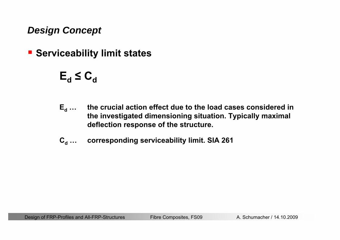
Design of FRP-Profiles and All-FRP-Structures Fibre Composites FS09 A Schumacher 14102009
Design Concept
Serviceability limit states
Ed le Cd
Ed hellip the crucial action effect due to the load cases considered inthe investigated dimensioning situation Typically maximaldeflection response of the structure
Cd hellip corresponding serviceability limit SIA 261
Design of FRP-Profiles and All-FRP-Structures Fibre Composites FS09 A Schumacher 14102009
Design Concept Basic Assumptions
Material Properties stength values (Fiberline Profiles)
Design of FRP-Profiles and All-FRP-Structures Fibre Composites FS09 A Schumacher 14102009
Design Concept Basic Assumptions
Material Properties stiffness values (Fiberline Profiles)
Design of FRP-Profiles and All-FRP-Structures Fibre Composites FS09 A Schumacher 14102009
Design Concept Basic Assumptions
Typical data sheet of a profile (Fiberline I-Profile)
Design of FRP-Profiles and All-FRP-Structures Fibre Composites FS09 A Schumacher 14102009
Bending Beam
Design of FRP-Profiles and All-FRP-Structures Fibre Composites FS09 A Schumacher 14102009
Bending Beam Design of hellip
Calculate bending moments Md and shear forces Qd acting on the profile using the partial coefficient (SIA 260 261)
Ultimate limit state
Bending
Shear
Ak hellip relevant shear area
d max d max 0max
M MW Wy z b
mzy
fσ γ
⎛ ⎞⎜ ⎟⎜ ⎟⎜ ⎟⎜ ⎟⎝ ⎠
deg= + le
d maxmax
kyAy
m
Q fττ γ= le
Design of FRP-Profiles and All-FRP-Structures Fibre Composites FS09 A Schumacher 14102009
Bending Beam Design of hellip
Serviceability limit state
Deflection limit
hellip typically selected between 200 and 400given by SIA 261 or the building owner
hellip calculated including shear deformations
Vibrations
Light-weighted and lsquosoftrsquo structures are susceptible to vibrations (traffic wind the movement of people hellip)
max 1wL αlt
α
maxw
Design of FRP-Profiles and All-FRP-Structures Fibre Composites FS09 A Schumacher 14102009
Bending Beam Timoshenko Theory
Pultruded profiles have a low shear modulus rarr shear deformation must be taken into account
Several bending theories have been published for beams
Euler-Bernoulli theory (1702)
Timoshenko theory (1968)
Higher order beam theory
A simply supported beam with a symmetric cross-section is discussed
Design of FRP-Profiles and All-FRP-Structures Fibre Composites FS09 A Schumacher 14102009
Bending Beam Timoshenko Theory
Cross-sections planeand perpendicular
1 degree of freedom
w
Cross-sections plane butNOT perpendicular
2 degrees of freedom
w and ψ
Cross-sections do NOTremain plane
3+ degrees of freedom
w ψ and hellip
Design of FRP-Profiles and All-FRP-Structures Fibre Composites FS09 A Schumacher 14102009
Bending Beam Euler vs Timoshenko Theory
Kinematic relationships
( )( )
( )
2 0
x x
y
xx xx
yxxy
u y w xu w x
u y w xxuu
y x
ε
ε
=minus sdot=
part= =minus sdotpartpartpart= + =
part part
( )( )
( )
2 ( ) ( )
x
y
xx x
yxxy x
u y xu w x
u y xxuu x w xy x
ψ
ε ψ
ε ψ
=minus sdot=
part= =minus sdotpartpartpart= + =minus +
part part
Hookrsquos law
0degE and G 2x x xy xyσ ε τ ε= sdot = sdot
z0deg E Iz x xxQS
M y dydz wσ= minus sdot sdot = sdot sdotintint
( )
z0deg E I
z x xQS
y xQS
M y dydz
Q dydz w GA
σ ψ
κ τ ψ κ
= minus sdot sdot = sdot
= sdot = minus sdot sdot
intint
intint
Design of FRP-Profiles and All-FRP-Structures Fibre Composites FS09 A Schumacher 14102009
Bending Beam Euler vs Timoshenko Theory
Equilibrium
Solution for the simply supported beam (distributed load)
In a first approximation the deflections are calculated by direct integration of
z0deg
( ) E IxxM xw = sdot
( )( )z0deg
( ) E I 0x
x
xx x
xx x
q x w GAw GA
QM Q
ψ κψ ψ κ
minus minus sdot sdot
sdot + minus sdot sdot
=minus =
= =minus
Equilibrium on an infinitesimal beam element
Coupled second order differential equation
21 1( ) (0) 0 and ( ) 02 2
M x qLx qx w w L= minus = =
( )3 2 3
0deg z
( ) 224 E Iqxw x L Lx x= sdot minus +sdot sdot
2
0deg z
1 1 1E I 2 2xxw qLx qx⎛ ⎞= minus⎜ ⎟sdot ⎝ ⎠
(0) 0 and ( ) 0(0) 0 (0) 0 and ( ) 0 ( ) 0 x x
w w LM M L Lψ ψ
= == rarr = = rarr =
Functions4 3 2
1 2 3 4 53 2
1 2 3 4
( )
( )
w x A x A x A x A x A
x B x B x B x Bψ
= + + + +
= + + +
Design of FRP-Profiles and All-FRP-Structures Fibre Composites FS09 A Schumacher 14102009
Put in and solve for the coefficients rarr
Bending Beam Euler vs Timoshenko Theory
Use the boundary conditions and the second differential eq to calculate A1 ndash A5
( )0deg z E I 0xx xw GAψ ψ κsdot + minus sdot sdot =
1 01 1 3 3
2 02 2 4 4
24 E I4 2GA
6 E I3 GA
z
z
AB A B A
AB A B A
κ
κ
deg
deg
sdot= minus = minus minus
sdotsdot
= minus = minus minussdot
( ) ( )( )2 2
0
( )2 GA 24 E Iz
qx L x L Lx xqx L xw x
κ deg
minus + minusminus= +
sdot sdot sdot
Deflection at midspan
4
0
52 384 E Iz
qLLw⎛ ⎞⎜ ⎟⎝ ⎠
deg
sdot= sdot4 2
0
52 384 E I 8 GAz
qL q LLw κ⎛ ⎞ +⎜ ⎟⎝ ⎠
deg
sdot sdot= sdot sdot sdot
Design of FRP-Profiles and All-FRP-Structures Fibre Composites FS09 A Schumacher 14102009
General expression for the total beam deflection as a sum of the deflection due to bending and shear
GAxf
IExfxwz sdot+=
deg κ)()()( 2
0
1
Cantilever beam
Simply supported
Concentrated load (P)
Uniformly distr load (q)
Concentrated load (P)
Uniformly distr load (q)
Beam )( max1 wf
3845 4qLsdot
48
3PL
8
4qL
3
3PL
)( max1 wf
8
2qL
4PL
2
2qL
PL
)( maxwx
2L
2L
L
L
Bending Beam Euler vs Timoshenko Theory
Design of FRP-Profiles and All-FRP-Structures Fibre Composites FS09 A Schumacher 14102009
Bending Beam Euler vs Timoshenko Theory
Example influence of the shear deformation
Profile 300 x 150 mm I-beam
Load uniformly distributed
General rule of thumbfor GFRP beams withspandepth gt 25 sheardeformation can beignored
Design of FRP-Profiles and All-FRP-Structures Fibre Composites FS09 A Schumacher 14102009
Bending Beam Example
Choose an appropriate Profile for the following specifications
1 Deflections and loading
=
=
==
1300 rarr wmax=001 mwmaxL
10 kNmqdser
13 kNmqduls
30 mL
max
4 2
0
5384 E I 8 GA
d ser d serz
q L q Lw κ+
deg
sdot sdot= sdot sdot sdot
2
maxz8 2 I
d ulsq L hσ sdot= sdot
maxky
12 Ad ulsq L
τ sdot=
Design of FRP-Profiles and All-FRP-Structures Fibre Composites FS09 A Schumacher 14102009
Bending Beam Example
2 Find a profile with sufficient bending stiffness
Shear deformations are neglected in a first step
rarr from specification table choose I 240x120x12 rarr
3 Check the bending and shear stresses
6 24
0 max
1054 10 Nm5
E I 384d ser
zq Lwdeg = sdot
sdotsdotge
6 20 1369 10 NmE Izdeg = sdot
2
maxz
358 MPa8 2 Id ulsq L hσ sdot= =sdot
max
ky
1 71 MPa2 Ad ulsq L
τ sdot= =
0 185 MPab df degle =
20 MPadfτle =
Design of FRP-Profiles and All-FRP-Structures Fibre Composites FS09 A Schumacher 14102009
Bending Beam Example
m10398384
5 32
0
4
maxminus
deg
sdot=sdotsdotsdot
+sdot
sdot=
GALq
IELq
w serd
z
serd
κ
4 Check deflection (including shear deformation)
5 Remarks
The design of GFRP-profiles is mostly driven by serviceability criteria
Start the design iteration procedure using the maximal deflection criterion
max 001 mwle =
m10198384
5 32
0
4
maxminus
deg
sdot=sdot
sdot+
sdotsdot
=web
serd
z
serd
GALq
IELq
w
(77 mm) (16 mm)
Design of FRP-Profiles and All-FRP-Structures Fibre Composites FS09 A Schumacher 14102009
Bending Beam Stability problems
Lateral-torsional bucklingFlange (compressive) displace laterally to the transverse load direction
Torsional stiffness is too low (especially for open section profiles)
Theoretical calculations or design measuresrarr see eg LP Kollaacuter 2003
Mechanics of composite structuresExample
Compressive flanges are kept in place by connection to the bridge deck
Design of FRP-Profiles and All-FRP-Structures Fibre Composites FS09 A Schumacher 14102009
Bending Beam Stability problems
Flange (compressive) displaces in the direction of the transverse load
Low bending stiffness perpendicular to the pultrusion direction
Weak fiber mats
Local buckling of walls due to in-plane compression
Local buckling of walls due to in-plane shear
Web crushing and web buckling in transverse direction
Design of FRP-Profiles and All-FRP-Structures Fibre Composites FS09 A Schumacher 14102009
Axial Members
Design of FRP-Profiles and All-FRP-Structures Fibre Composites FS09 A Schumacher 14102009
Axial Members Tension
Ultimate limit state under axial tension Nd
Serviceability limit state
Remark The critical aspect of axial members in tension are neither the serviceability nor the ultimate limit state Critical is the load transfer to the GFRP profile
0NdA
tm
fγ
degle
0deg
N LE Axδ sdot= sdot
Design of FRP-Profiles and All-FRP-Structures Fibre Composites FS09 A Schumacher 14102009
Axial Members Compression
Ultimate limit state under axial compression Nd
hellip maximal compressive load
hellip Euler load
hellip Buckling length for columns
hellip coefficient for Youngrsquos modulus = 13
cc
Euler
FNd F1 N
le+
c0degC
A fF
mγsdot
=
20
Euler 2
Nm E k
E IL
πγ
degsdot sdot=
sdot
kL
m Eγ
Design of FRP-Profiles and All-FRP-Structures Fibre Composites FS09 A Schumacher 14102009
Axial Members Compression
The influence of shear deformation should be considered but in the most cases the influence will be small (less than 5)
Local buckling should be considered for short columns
For more information on the various buckling modes and effects rarr see LP Kollaacuter 2003 Mechanics of composite structures
Global buckling Local buckling
Design of FRP-Profiles and All-FRP-Structures Fibre Composites FS09 A Schumacher 14102009
Connections
Design of FRP-Profiles and All-FRP-Structures Fibre Composites FS09 A Schumacher 14102009
Connections Introduction
Design of FRP-Profiles and All-FRP-Structures Fibre Composites FS09 A Schumacher 14102009
Connections Introduction
(from Eurocomp Design Code 1996)
Design of FRP-Profiles and All-FRP-Structures Fibre Composites FS09 A Schumacher 14102009
Connections Bolted joints
Bolts = Stress concentration in the profile and the bolt
It is necessary to ensure that the bolts and the profilecan withstand this concentrated local stress compression
It is necessary to ensure that the region surroundinga group of bolts will not be torn out of the profile
Basic failure modesin bolted shearconnections
bolt shear failure
Design of FRP-Profiles and All-FRP-Structures Fibre Composites FS09 A Schumacher 14102009
Connections Bolted joints
The design procedure is comparable to the one for steel connections but since there exist no standard GFRP material rarr each manufacturer has its own design rules for bolted joints
IMPORTANT REMARKS
The direction of pultrusion and the direction of the force is RELEVANT(anisotropic material)
Use stainless or galvanised steel
Do not cut threads in the composite material
Use screws with shafts
Design of FRP-Profiles and All-FRP-Structures Fibre Composites FS09 A Schumacher 14102009
Calculation of load bearing capacity of bolts
Shear in longitudinal direction (0deg)
Shear in transverse direction (90deg)
Tensile force
Minimum distances
Connections Bolted joints (Fiberline recommendations)
Design of FRP-Profiles and All-FRP-Structures Fibre Composites FS09 A Schumacher 14102009
Joint capacity tables available for shear and tension
m
150 MPa( 13)B d
d tP γsdot sdot=
=
Shear in longitudinal direction 0deg
m
70 MPa( 13)B d
d tP γsdot sdot=
=
Shear in transverse direction 90deg
Connections Bolted joints (Fiberline recommendations)
Design of FRP-Profiles and All-FRP-Structures Fibre Composites FS09 A Schumacher 14102009
Bolted connection in shear eg shear in longitudinal direction
Connections Bolted joints (Fiberline recommendations)
γmPBolt le dt720 MPaγmPBolt le dt240 MPa
γmPBolt le dt240 MPa γmPBolt le dt240 MPaγmPBolt le dt150 MPa
Design of FRP-Profiles and All-FRP-Structures Fibre Composites FS09 A Schumacher 14102009
Bolted connections in tension
Static conditions
Bolt Tearing of bolt in threaded cross-section
Laminate Shear fracture at rim of washer
Geometry and strength
Diameter of washer2d
Tensile strength of bolt hellipfyk
Shear strength of laminatehellipfτ
Thickness of laminatet
Stress area of the boltAs
Diameter of the boltd
s ykd m
A fP γ
sdotle
2d m
d t fP τπγ
sdot sdot sdot sdotle
Connections Bolted joints (Fiberline recommendations)
Design of FRP-Profiles and All-FRP-Structures Fibre Composites FS09 A Schumacher 14102009
Connections Bonded joints
Using an adhesive agent for joining profiles can have advantages
Easy to use easy to make aesthetic joints
Typically more rigid than bolted joints
Glued joints subjected to dynamic loads are good
But be careful hellipAdhesive agents have properties that depend on time temperature humidity hellip
Failure in glued joints takes place suddenly (brittle behaviour)
The load-bearing capacity is not proportional to the area which is glued
The design of bonded joints may be based onAnalytical models for plate-to-plate connections (see Eurocomp 1996 Design Code)
Design guidelines supplemented by testing
Finite element analysis
Design of FRP-Profiles and All-FRP-Structures Fibre Composites FS09 A Schumacher 14102009
Connections Bonded joints
A bonded joint has the following three primary failure modes
adhesive failure
cohesive failure of adhesive
cohesive failure of adherend
The design of any bonded joint shall satisfy the following conditions
allowable shear stress in the adhesive is not exceeded
allowable tensile (peel) stress in the adhesive is not exceeded
allowable through-thickness tensile stress of the adhesive is not exceeded
allowable in-plane shear stress of the adherend should not be exceeded
The calculation of the stresses has to be done very carefully Often calculations are supplemented by testing
Design of FRP-Profiles and All-FRP-Structures Fibre Composites FS09 A Schumacher 14102009
Connections Bonded joints
Different types of bonded joint configurations
Research on bonded joints for structuralapplications
Design of FRP-Profiles and All-FRP-Structures Fibre Composites FS09 A Schumacher 14102009
Connections Other joints
Brackets for assembly (Fiberline)
Custom pultruded connections
Design of FRP-Profiles and All-FRP-Structures Fibre Composites FS09 A Schumacher 14102009
GFRP Some final remarks
Perpendicular to the direction of pultrusion the material is WEAK and SOFTrarr avoid such loadings if possible
In order to use pultruded GFRP-profiles economically the design must be done in a clever way eg for bridges the railings should be used as part of the load-bearing structure
GFRP structures are very light rarr vibration problems may occur
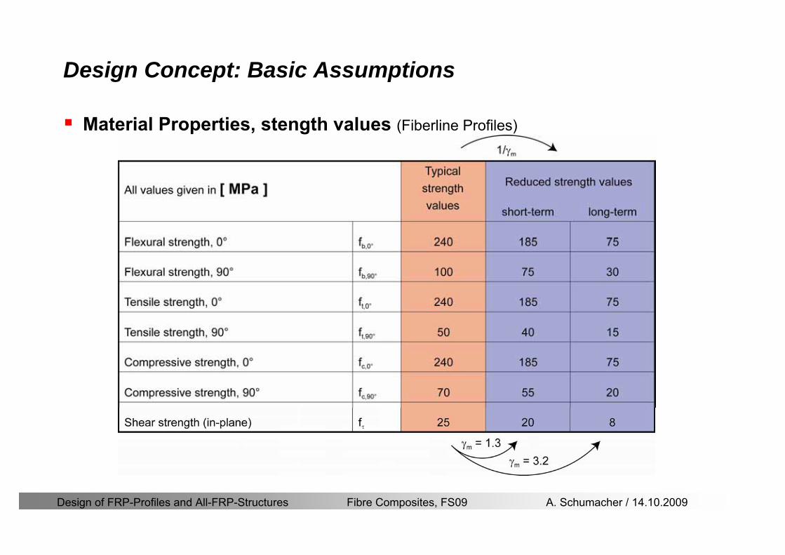
Design of FRP-Profiles and All-FRP-Structures Fibre Composites FS09 A Schumacher 14102009
Design Concept Basic Assumptions
Material Properties stength values (Fiberline Profiles)
Design of FRP-Profiles and All-FRP-Structures Fibre Composites FS09 A Schumacher 14102009
Design Concept Basic Assumptions
Material Properties stiffness values (Fiberline Profiles)
Design of FRP-Profiles and All-FRP-Structures Fibre Composites FS09 A Schumacher 14102009
Design Concept Basic Assumptions
Typical data sheet of a profile (Fiberline I-Profile)
Design of FRP-Profiles and All-FRP-Structures Fibre Composites FS09 A Schumacher 14102009
Bending Beam
Design of FRP-Profiles and All-FRP-Structures Fibre Composites FS09 A Schumacher 14102009
Bending Beam Design of hellip
Calculate bending moments Md and shear forces Qd acting on the profile using the partial coefficient (SIA 260 261)
Ultimate limit state
Bending
Shear
Ak hellip relevant shear area
d max d max 0max
M MW Wy z b
mzy
fσ γ
⎛ ⎞⎜ ⎟⎜ ⎟⎜ ⎟⎜ ⎟⎝ ⎠
deg= + le
d maxmax
kyAy
m
Q fττ γ= le
Design of FRP-Profiles and All-FRP-Structures Fibre Composites FS09 A Schumacher 14102009
Bending Beam Design of hellip
Serviceability limit state
Deflection limit
hellip typically selected between 200 and 400given by SIA 261 or the building owner
hellip calculated including shear deformations
Vibrations
Light-weighted and lsquosoftrsquo structures are susceptible to vibrations (traffic wind the movement of people hellip)
max 1wL αlt
α
maxw
Design of FRP-Profiles and All-FRP-Structures Fibre Composites FS09 A Schumacher 14102009
Bending Beam Timoshenko Theory
Pultruded profiles have a low shear modulus rarr shear deformation must be taken into account
Several bending theories have been published for beams
Euler-Bernoulli theory (1702)
Timoshenko theory (1968)
Higher order beam theory
A simply supported beam with a symmetric cross-section is discussed
Design of FRP-Profiles and All-FRP-Structures Fibre Composites FS09 A Schumacher 14102009
Bending Beam Timoshenko Theory
Cross-sections planeand perpendicular
1 degree of freedom
w
Cross-sections plane butNOT perpendicular
2 degrees of freedom
w and ψ
Cross-sections do NOTremain plane
3+ degrees of freedom
w ψ and hellip
Design of FRP-Profiles and All-FRP-Structures Fibre Composites FS09 A Schumacher 14102009
Bending Beam Euler vs Timoshenko Theory
Kinematic relationships
( )( )
( )
2 0
x x
y
xx xx
yxxy
u y w xu w x
u y w xxuu
y x
ε
ε
=minus sdot=
part= =minus sdotpartpartpart= + =
part part
( )( )
( )
2 ( ) ( )
x
y
xx x
yxxy x
u y xu w x
u y xxuu x w xy x
ψ
ε ψ
ε ψ
=minus sdot=
part= =minus sdotpartpartpart= + =minus +
part part
Hookrsquos law
0degE and G 2x x xy xyσ ε τ ε= sdot = sdot
z0deg E Iz x xxQS
M y dydz wσ= minus sdot sdot = sdot sdotintint
( )
z0deg E I
z x xQS
y xQS
M y dydz
Q dydz w GA
σ ψ
κ τ ψ κ
= minus sdot sdot = sdot
= sdot = minus sdot sdot
intint
intint
Design of FRP-Profiles and All-FRP-Structures Fibre Composites FS09 A Schumacher 14102009
Bending Beam Euler vs Timoshenko Theory
Equilibrium
Solution for the simply supported beam (distributed load)
In a first approximation the deflections are calculated by direct integration of
z0deg
( ) E IxxM xw = sdot
( )( )z0deg
( ) E I 0x
x
xx x
xx x
q x w GAw GA
QM Q
ψ κψ ψ κ
minus minus sdot sdot
sdot + minus sdot sdot
=minus =
= =minus
Equilibrium on an infinitesimal beam element
Coupled second order differential equation
21 1( ) (0) 0 and ( ) 02 2
M x qLx qx w w L= minus = =
( )3 2 3
0deg z
( ) 224 E Iqxw x L Lx x= sdot minus +sdot sdot
2
0deg z
1 1 1E I 2 2xxw qLx qx⎛ ⎞= minus⎜ ⎟sdot ⎝ ⎠
(0) 0 and ( ) 0(0) 0 (0) 0 and ( ) 0 ( ) 0 x x
w w LM M L Lψ ψ
= == rarr = = rarr =
Functions4 3 2
1 2 3 4 53 2
1 2 3 4
( )
( )
w x A x A x A x A x A
x B x B x B x Bψ
= + + + +
= + + +
Design of FRP-Profiles and All-FRP-Structures Fibre Composites FS09 A Schumacher 14102009
Put in and solve for the coefficients rarr
Bending Beam Euler vs Timoshenko Theory
Use the boundary conditions and the second differential eq to calculate A1 ndash A5
( )0deg z E I 0xx xw GAψ ψ κsdot + minus sdot sdot =
1 01 1 3 3
2 02 2 4 4
24 E I4 2GA
6 E I3 GA
z
z
AB A B A
AB A B A
κ
κ
deg
deg
sdot= minus = minus minus
sdotsdot
= minus = minus minussdot
( ) ( )( )2 2
0
( )2 GA 24 E Iz
qx L x L Lx xqx L xw x
κ deg
minus + minusminus= +
sdot sdot sdot
Deflection at midspan
4
0
52 384 E Iz
qLLw⎛ ⎞⎜ ⎟⎝ ⎠
deg
sdot= sdot4 2
0
52 384 E I 8 GAz
qL q LLw κ⎛ ⎞ +⎜ ⎟⎝ ⎠
deg
sdot sdot= sdot sdot sdot
Design of FRP-Profiles and All-FRP-Structures Fibre Composites FS09 A Schumacher 14102009
General expression for the total beam deflection as a sum of the deflection due to bending and shear
GAxf
IExfxwz sdot+=
deg κ)()()( 2
0
1
Cantilever beam
Simply supported
Concentrated load (P)
Uniformly distr load (q)
Concentrated load (P)
Uniformly distr load (q)
Beam )( max1 wf
3845 4qLsdot
48
3PL
8
4qL
3
3PL
)( max1 wf
8
2qL
4PL
2
2qL
PL
)( maxwx
2L
2L
L
L
Bending Beam Euler vs Timoshenko Theory
Design of FRP-Profiles and All-FRP-Structures Fibre Composites FS09 A Schumacher 14102009
Bending Beam Euler vs Timoshenko Theory
Example influence of the shear deformation
Profile 300 x 150 mm I-beam
Load uniformly distributed
General rule of thumbfor GFRP beams withspandepth gt 25 sheardeformation can beignored
Design of FRP-Profiles and All-FRP-Structures Fibre Composites FS09 A Schumacher 14102009
Bending Beam Example
Choose an appropriate Profile for the following specifications
1 Deflections and loading
=
=
==
1300 rarr wmax=001 mwmaxL
10 kNmqdser
13 kNmqduls
30 mL
max
4 2
0
5384 E I 8 GA
d ser d serz
q L q Lw κ+
deg
sdot sdot= sdot sdot sdot
2
maxz8 2 I
d ulsq L hσ sdot= sdot
maxky
12 Ad ulsq L
τ sdot=
Design of FRP-Profiles and All-FRP-Structures Fibre Composites FS09 A Schumacher 14102009
Bending Beam Example
2 Find a profile with sufficient bending stiffness
Shear deformations are neglected in a first step
rarr from specification table choose I 240x120x12 rarr
3 Check the bending and shear stresses
6 24
0 max
1054 10 Nm5
E I 384d ser
zq Lwdeg = sdot
sdotsdotge
6 20 1369 10 NmE Izdeg = sdot
2
maxz
358 MPa8 2 Id ulsq L hσ sdot= =sdot
max
ky
1 71 MPa2 Ad ulsq L
τ sdot= =
0 185 MPab df degle =
20 MPadfτle =
Design of FRP-Profiles and All-FRP-Structures Fibre Composites FS09 A Schumacher 14102009
Bending Beam Example
m10398384
5 32
0
4
maxminus
deg
sdot=sdotsdotsdot
+sdot
sdot=
GALq
IELq
w serd
z
serd
κ
4 Check deflection (including shear deformation)
5 Remarks
The design of GFRP-profiles is mostly driven by serviceability criteria
Start the design iteration procedure using the maximal deflection criterion
max 001 mwle =
m10198384
5 32
0
4
maxminus
deg
sdot=sdot
sdot+
sdotsdot
=web
serd
z
serd
GALq
IELq
w
(77 mm) (16 mm)
Design of FRP-Profiles and All-FRP-Structures Fibre Composites FS09 A Schumacher 14102009
Bending Beam Stability problems
Lateral-torsional bucklingFlange (compressive) displace laterally to the transverse load direction
Torsional stiffness is too low (especially for open section profiles)
Theoretical calculations or design measuresrarr see eg LP Kollaacuter 2003
Mechanics of composite structuresExample
Compressive flanges are kept in place by connection to the bridge deck
Design of FRP-Profiles and All-FRP-Structures Fibre Composites FS09 A Schumacher 14102009
Bending Beam Stability problems
Flange (compressive) displaces in the direction of the transverse load
Low bending stiffness perpendicular to the pultrusion direction
Weak fiber mats
Local buckling of walls due to in-plane compression
Local buckling of walls due to in-plane shear
Web crushing and web buckling in transverse direction
Design of FRP-Profiles and All-FRP-Structures Fibre Composites FS09 A Schumacher 14102009
Axial Members
Design of FRP-Profiles and All-FRP-Structures Fibre Composites FS09 A Schumacher 14102009
Axial Members Tension
Ultimate limit state under axial tension Nd
Serviceability limit state
Remark The critical aspect of axial members in tension are neither the serviceability nor the ultimate limit state Critical is the load transfer to the GFRP profile
0NdA
tm
fγ
degle
0deg
N LE Axδ sdot= sdot
Design of FRP-Profiles and All-FRP-Structures Fibre Composites FS09 A Schumacher 14102009
Axial Members Compression
Ultimate limit state under axial compression Nd
hellip maximal compressive load
hellip Euler load
hellip Buckling length for columns
hellip coefficient for Youngrsquos modulus = 13
cc
Euler
FNd F1 N
le+
c0degC
A fF
mγsdot
=
20
Euler 2
Nm E k
E IL
πγ
degsdot sdot=
sdot
kL
m Eγ
Design of FRP-Profiles and All-FRP-Structures Fibre Composites FS09 A Schumacher 14102009
Axial Members Compression
The influence of shear deformation should be considered but in the most cases the influence will be small (less than 5)
Local buckling should be considered for short columns
For more information on the various buckling modes and effects rarr see LP Kollaacuter 2003 Mechanics of composite structures
Global buckling Local buckling
Design of FRP-Profiles and All-FRP-Structures Fibre Composites FS09 A Schumacher 14102009
Connections
Design of FRP-Profiles and All-FRP-Structures Fibre Composites FS09 A Schumacher 14102009
Connections Introduction
Design of FRP-Profiles and All-FRP-Structures Fibre Composites FS09 A Schumacher 14102009
Connections Introduction
(from Eurocomp Design Code 1996)
Design of FRP-Profiles and All-FRP-Structures Fibre Composites FS09 A Schumacher 14102009
Connections Bolted joints
Bolts = Stress concentration in the profile and the bolt
It is necessary to ensure that the bolts and the profilecan withstand this concentrated local stress compression
It is necessary to ensure that the region surroundinga group of bolts will not be torn out of the profile
Basic failure modesin bolted shearconnections
bolt shear failure
Design of FRP-Profiles and All-FRP-Structures Fibre Composites FS09 A Schumacher 14102009
Connections Bolted joints
The design procedure is comparable to the one for steel connections but since there exist no standard GFRP material rarr each manufacturer has its own design rules for bolted joints
IMPORTANT REMARKS
The direction of pultrusion and the direction of the force is RELEVANT(anisotropic material)
Use stainless or galvanised steel
Do not cut threads in the composite material
Use screws with shafts
Design of FRP-Profiles and All-FRP-Structures Fibre Composites FS09 A Schumacher 14102009
Calculation of load bearing capacity of bolts
Shear in longitudinal direction (0deg)
Shear in transverse direction (90deg)
Tensile force
Minimum distances
Connections Bolted joints (Fiberline recommendations)
Design of FRP-Profiles and All-FRP-Structures Fibre Composites FS09 A Schumacher 14102009
Joint capacity tables available for shear and tension
m
150 MPa( 13)B d
d tP γsdot sdot=
=
Shear in longitudinal direction 0deg
m
70 MPa( 13)B d
d tP γsdot sdot=
=
Shear in transverse direction 90deg
Connections Bolted joints (Fiberline recommendations)
Design of FRP-Profiles and All-FRP-Structures Fibre Composites FS09 A Schumacher 14102009
Bolted connection in shear eg shear in longitudinal direction
Connections Bolted joints (Fiberline recommendations)
γmPBolt le dt720 MPaγmPBolt le dt240 MPa
γmPBolt le dt240 MPa γmPBolt le dt240 MPaγmPBolt le dt150 MPa
Design of FRP-Profiles and All-FRP-Structures Fibre Composites FS09 A Schumacher 14102009
Bolted connections in tension
Static conditions
Bolt Tearing of bolt in threaded cross-section
Laminate Shear fracture at rim of washer
Geometry and strength
Diameter of washer2d
Tensile strength of bolt hellipfyk
Shear strength of laminatehellipfτ
Thickness of laminatet
Stress area of the boltAs
Diameter of the boltd
s ykd m
A fP γ
sdotle
2d m
d t fP τπγ
sdot sdot sdot sdotle
Connections Bolted joints (Fiberline recommendations)
Design of FRP-Profiles and All-FRP-Structures Fibre Composites FS09 A Schumacher 14102009
Connections Bonded joints
Using an adhesive agent for joining profiles can have advantages
Easy to use easy to make aesthetic joints
Typically more rigid than bolted joints
Glued joints subjected to dynamic loads are good
But be careful hellipAdhesive agents have properties that depend on time temperature humidity hellip
Failure in glued joints takes place suddenly (brittle behaviour)
The load-bearing capacity is not proportional to the area which is glued
The design of bonded joints may be based onAnalytical models for plate-to-plate connections (see Eurocomp 1996 Design Code)
Design guidelines supplemented by testing
Finite element analysis
Design of FRP-Profiles and All-FRP-Structures Fibre Composites FS09 A Schumacher 14102009
Connections Bonded joints
A bonded joint has the following three primary failure modes
adhesive failure
cohesive failure of adhesive
cohesive failure of adherend
The design of any bonded joint shall satisfy the following conditions
allowable shear stress in the adhesive is not exceeded
allowable tensile (peel) stress in the adhesive is not exceeded
allowable through-thickness tensile stress of the adhesive is not exceeded
allowable in-plane shear stress of the adherend should not be exceeded
The calculation of the stresses has to be done very carefully Often calculations are supplemented by testing
Design of FRP-Profiles and All-FRP-Structures Fibre Composites FS09 A Schumacher 14102009
Connections Bonded joints
Different types of bonded joint configurations
Research on bonded joints for structuralapplications
Design of FRP-Profiles and All-FRP-Structures Fibre Composites FS09 A Schumacher 14102009
Connections Other joints
Brackets for assembly (Fiberline)
Custom pultruded connections
Design of FRP-Profiles and All-FRP-Structures Fibre Composites FS09 A Schumacher 14102009
GFRP Some final remarks
Perpendicular to the direction of pultrusion the material is WEAK and SOFTrarr avoid such loadings if possible
In order to use pultruded GFRP-profiles economically the design must be done in a clever way eg for bridges the railings should be used as part of the load-bearing structure
GFRP structures are very light rarr vibration problems may occur
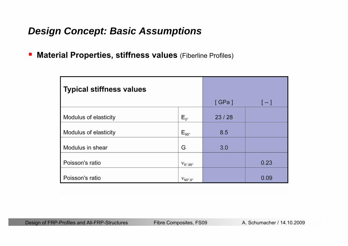
Design of FRP-Profiles and All-FRP-Structures Fibre Composites FS09 A Schumacher 14102009
Design Concept Basic Assumptions
Material Properties stiffness values (Fiberline Profiles)
Design of FRP-Profiles and All-FRP-Structures Fibre Composites FS09 A Schumacher 14102009
Design Concept Basic Assumptions
Typical data sheet of a profile (Fiberline I-Profile)
Design of FRP-Profiles and All-FRP-Structures Fibre Composites FS09 A Schumacher 14102009
Bending Beam
Design of FRP-Profiles and All-FRP-Structures Fibre Composites FS09 A Schumacher 14102009
Bending Beam Design of hellip
Calculate bending moments Md and shear forces Qd acting on the profile using the partial coefficient (SIA 260 261)
Ultimate limit state
Bending
Shear
Ak hellip relevant shear area
d max d max 0max
M MW Wy z b
mzy
fσ γ
⎛ ⎞⎜ ⎟⎜ ⎟⎜ ⎟⎜ ⎟⎝ ⎠
deg= + le
d maxmax
kyAy
m
Q fττ γ= le
Design of FRP-Profiles and All-FRP-Structures Fibre Composites FS09 A Schumacher 14102009
Bending Beam Design of hellip
Serviceability limit state
Deflection limit
hellip typically selected between 200 and 400given by SIA 261 or the building owner
hellip calculated including shear deformations
Vibrations
Light-weighted and lsquosoftrsquo structures are susceptible to vibrations (traffic wind the movement of people hellip)
max 1wL αlt
α
maxw
Design of FRP-Profiles and All-FRP-Structures Fibre Composites FS09 A Schumacher 14102009
Bending Beam Timoshenko Theory
Pultruded profiles have a low shear modulus rarr shear deformation must be taken into account
Several bending theories have been published for beams
Euler-Bernoulli theory (1702)
Timoshenko theory (1968)
Higher order beam theory
A simply supported beam with a symmetric cross-section is discussed
Design of FRP-Profiles and All-FRP-Structures Fibre Composites FS09 A Schumacher 14102009
Bending Beam Timoshenko Theory
Cross-sections planeand perpendicular
1 degree of freedom
w
Cross-sections plane butNOT perpendicular
2 degrees of freedom
w and ψ
Cross-sections do NOTremain plane
3+ degrees of freedom
w ψ and hellip
Design of FRP-Profiles and All-FRP-Structures Fibre Composites FS09 A Schumacher 14102009
Bending Beam Euler vs Timoshenko Theory
Kinematic relationships
( )( )
( )
2 0
x x
y
xx xx
yxxy
u y w xu w x
u y w xxuu
y x
ε
ε
=minus sdot=
part= =minus sdotpartpartpart= + =
part part
( )( )
( )
2 ( ) ( )
x
y
xx x
yxxy x
u y xu w x
u y xxuu x w xy x
ψ
ε ψ
ε ψ
=minus sdot=
part= =minus sdotpartpartpart= + =minus +
part part
Hookrsquos law
0degE and G 2x x xy xyσ ε τ ε= sdot = sdot
z0deg E Iz x xxQS
M y dydz wσ= minus sdot sdot = sdot sdotintint
( )
z0deg E I
z x xQS
y xQS
M y dydz
Q dydz w GA
σ ψ
κ τ ψ κ
= minus sdot sdot = sdot
= sdot = minus sdot sdot
intint
intint
Design of FRP-Profiles and All-FRP-Structures Fibre Composites FS09 A Schumacher 14102009
Bending Beam Euler vs Timoshenko Theory
Equilibrium
Solution for the simply supported beam (distributed load)
In a first approximation the deflections are calculated by direct integration of
z0deg
( ) E IxxM xw = sdot
( )( )z0deg
( ) E I 0x
x
xx x
xx x
q x w GAw GA
QM Q
ψ κψ ψ κ
minus minus sdot sdot
sdot + minus sdot sdot
=minus =
= =minus
Equilibrium on an infinitesimal beam element
Coupled second order differential equation
21 1( ) (0) 0 and ( ) 02 2
M x qLx qx w w L= minus = =
( )3 2 3
0deg z
( ) 224 E Iqxw x L Lx x= sdot minus +sdot sdot
2
0deg z
1 1 1E I 2 2xxw qLx qx⎛ ⎞= minus⎜ ⎟sdot ⎝ ⎠
(0) 0 and ( ) 0(0) 0 (0) 0 and ( ) 0 ( ) 0 x x
w w LM M L Lψ ψ
= == rarr = = rarr =
Functions4 3 2
1 2 3 4 53 2
1 2 3 4
( )
( )
w x A x A x A x A x A
x B x B x B x Bψ
= + + + +
= + + +
Design of FRP-Profiles and All-FRP-Structures Fibre Composites FS09 A Schumacher 14102009
Put in and solve for the coefficients rarr
Bending Beam Euler vs Timoshenko Theory
Use the boundary conditions and the second differential eq to calculate A1 ndash A5
( )0deg z E I 0xx xw GAψ ψ κsdot + minus sdot sdot =
1 01 1 3 3
2 02 2 4 4
24 E I4 2GA
6 E I3 GA
z
z
AB A B A
AB A B A
κ
κ
deg
deg
sdot= minus = minus minus
sdotsdot
= minus = minus minussdot
( ) ( )( )2 2
0
( )2 GA 24 E Iz
qx L x L Lx xqx L xw x
κ deg
minus + minusminus= +
sdot sdot sdot
Deflection at midspan
4
0
52 384 E Iz
qLLw⎛ ⎞⎜ ⎟⎝ ⎠
deg
sdot= sdot4 2
0
52 384 E I 8 GAz
qL q LLw κ⎛ ⎞ +⎜ ⎟⎝ ⎠
deg
sdot sdot= sdot sdot sdot
Design of FRP-Profiles and All-FRP-Structures Fibre Composites FS09 A Schumacher 14102009
General expression for the total beam deflection as a sum of the deflection due to bending and shear
GAxf
IExfxwz sdot+=
deg κ)()()( 2
0
1
Cantilever beam
Simply supported
Concentrated load (P)
Uniformly distr load (q)
Concentrated load (P)
Uniformly distr load (q)
Beam )( max1 wf
3845 4qLsdot
48
3PL
8
4qL
3
3PL
)( max1 wf
8
2qL
4PL
2
2qL
PL
)( maxwx
2L
2L
L
L
Bending Beam Euler vs Timoshenko Theory
Design of FRP-Profiles and All-FRP-Structures Fibre Composites FS09 A Schumacher 14102009
Bending Beam Euler vs Timoshenko Theory
Example influence of the shear deformation
Profile 300 x 150 mm I-beam
Load uniformly distributed
General rule of thumbfor GFRP beams withspandepth gt 25 sheardeformation can beignored
Design of FRP-Profiles and All-FRP-Structures Fibre Composites FS09 A Schumacher 14102009
Bending Beam Example
Choose an appropriate Profile for the following specifications
1 Deflections and loading
=
=
==
1300 rarr wmax=001 mwmaxL
10 kNmqdser
13 kNmqduls
30 mL
max
4 2
0
5384 E I 8 GA
d ser d serz
q L q Lw κ+
deg
sdot sdot= sdot sdot sdot
2
maxz8 2 I
d ulsq L hσ sdot= sdot
maxky
12 Ad ulsq L
τ sdot=
Design of FRP-Profiles and All-FRP-Structures Fibre Composites FS09 A Schumacher 14102009
Bending Beam Example
2 Find a profile with sufficient bending stiffness
Shear deformations are neglected in a first step
rarr from specification table choose I 240x120x12 rarr
3 Check the bending and shear stresses
6 24
0 max
1054 10 Nm5
E I 384d ser
zq Lwdeg = sdot
sdotsdotge
6 20 1369 10 NmE Izdeg = sdot
2
maxz
358 MPa8 2 Id ulsq L hσ sdot= =sdot
max
ky
1 71 MPa2 Ad ulsq L
τ sdot= =
0 185 MPab df degle =
20 MPadfτle =
Design of FRP-Profiles and All-FRP-Structures Fibre Composites FS09 A Schumacher 14102009
Bending Beam Example
m10398384
5 32
0
4
maxminus
deg
sdot=sdotsdotsdot
+sdot
sdot=
GALq
IELq
w serd
z
serd
κ
4 Check deflection (including shear deformation)
5 Remarks
The design of GFRP-profiles is mostly driven by serviceability criteria
Start the design iteration procedure using the maximal deflection criterion
max 001 mwle =
m10198384
5 32
0
4
maxminus
deg
sdot=sdot
sdot+
sdotsdot
=web
serd
z
serd
GALq
IELq
w
(77 mm) (16 mm)
Design of FRP-Profiles and All-FRP-Structures Fibre Composites FS09 A Schumacher 14102009
Bending Beam Stability problems
Lateral-torsional bucklingFlange (compressive) displace laterally to the transverse load direction
Torsional stiffness is too low (especially for open section profiles)
Theoretical calculations or design measuresrarr see eg LP Kollaacuter 2003
Mechanics of composite structuresExample
Compressive flanges are kept in place by connection to the bridge deck
Design of FRP-Profiles and All-FRP-Structures Fibre Composites FS09 A Schumacher 14102009
Bending Beam Stability problems
Flange (compressive) displaces in the direction of the transverse load
Low bending stiffness perpendicular to the pultrusion direction
Weak fiber mats
Local buckling of walls due to in-plane compression
Local buckling of walls due to in-plane shear
Web crushing and web buckling in transverse direction
Design of FRP-Profiles and All-FRP-Structures Fibre Composites FS09 A Schumacher 14102009
Axial Members
Design of FRP-Profiles and All-FRP-Structures Fibre Composites FS09 A Schumacher 14102009
Axial Members Tension
Ultimate limit state under axial tension Nd
Serviceability limit state
Remark The critical aspect of axial members in tension are neither the serviceability nor the ultimate limit state Critical is the load transfer to the GFRP profile
0NdA
tm
fγ
degle
0deg
N LE Axδ sdot= sdot
Design of FRP-Profiles and All-FRP-Structures Fibre Composites FS09 A Schumacher 14102009
Axial Members Compression
Ultimate limit state under axial compression Nd
hellip maximal compressive load
hellip Euler load
hellip Buckling length for columns
hellip coefficient for Youngrsquos modulus = 13
cc
Euler
FNd F1 N
le+
c0degC
A fF
mγsdot
=
20
Euler 2
Nm E k
E IL
πγ
degsdot sdot=
sdot
kL
m Eγ
Design of FRP-Profiles and All-FRP-Structures Fibre Composites FS09 A Schumacher 14102009
Axial Members Compression
The influence of shear deformation should be considered but in the most cases the influence will be small (less than 5)
Local buckling should be considered for short columns
For more information on the various buckling modes and effects rarr see LP Kollaacuter 2003 Mechanics of composite structures
Global buckling Local buckling
Design of FRP-Profiles and All-FRP-Structures Fibre Composites FS09 A Schumacher 14102009
Connections
Design of FRP-Profiles and All-FRP-Structures Fibre Composites FS09 A Schumacher 14102009
Connections Introduction
Design of FRP-Profiles and All-FRP-Structures Fibre Composites FS09 A Schumacher 14102009
Connections Introduction
(from Eurocomp Design Code 1996)
Design of FRP-Profiles and All-FRP-Structures Fibre Composites FS09 A Schumacher 14102009
Connections Bolted joints
Bolts = Stress concentration in the profile and the bolt
It is necessary to ensure that the bolts and the profilecan withstand this concentrated local stress compression
It is necessary to ensure that the region surroundinga group of bolts will not be torn out of the profile
Basic failure modesin bolted shearconnections
bolt shear failure
Design of FRP-Profiles and All-FRP-Structures Fibre Composites FS09 A Schumacher 14102009
Connections Bolted joints
The design procedure is comparable to the one for steel connections but since there exist no standard GFRP material rarr each manufacturer has its own design rules for bolted joints
IMPORTANT REMARKS
The direction of pultrusion and the direction of the force is RELEVANT(anisotropic material)
Use stainless or galvanised steel
Do not cut threads in the composite material
Use screws with shafts
Design of FRP-Profiles and All-FRP-Structures Fibre Composites FS09 A Schumacher 14102009
Calculation of load bearing capacity of bolts
Shear in longitudinal direction (0deg)
Shear in transverse direction (90deg)
Tensile force
Minimum distances
Connections Bolted joints (Fiberline recommendations)
Design of FRP-Profiles and All-FRP-Structures Fibre Composites FS09 A Schumacher 14102009
Joint capacity tables available for shear and tension
m
150 MPa( 13)B d
d tP γsdot sdot=
=
Shear in longitudinal direction 0deg
m
70 MPa( 13)B d
d tP γsdot sdot=
=
Shear in transverse direction 90deg
Connections Bolted joints (Fiberline recommendations)
Design of FRP-Profiles and All-FRP-Structures Fibre Composites FS09 A Schumacher 14102009
Bolted connection in shear eg shear in longitudinal direction
Connections Bolted joints (Fiberline recommendations)
γmPBolt le dt720 MPaγmPBolt le dt240 MPa
γmPBolt le dt240 MPa γmPBolt le dt240 MPaγmPBolt le dt150 MPa
Design of FRP-Profiles and All-FRP-Structures Fibre Composites FS09 A Schumacher 14102009
Bolted connections in tension
Static conditions
Bolt Tearing of bolt in threaded cross-section
Laminate Shear fracture at rim of washer
Geometry and strength
Diameter of washer2d
Tensile strength of bolt hellipfyk
Shear strength of laminatehellipfτ
Thickness of laminatet
Stress area of the boltAs
Diameter of the boltd
s ykd m
A fP γ
sdotle
2d m
d t fP τπγ
sdot sdot sdot sdotle
Connections Bolted joints (Fiberline recommendations)
Design of FRP-Profiles and All-FRP-Structures Fibre Composites FS09 A Schumacher 14102009
Connections Bonded joints
Using an adhesive agent for joining profiles can have advantages
Easy to use easy to make aesthetic joints
Typically more rigid than bolted joints
Glued joints subjected to dynamic loads are good
But be careful hellipAdhesive agents have properties that depend on time temperature humidity hellip
Failure in glued joints takes place suddenly (brittle behaviour)
The load-bearing capacity is not proportional to the area which is glued
The design of bonded joints may be based onAnalytical models for plate-to-plate connections (see Eurocomp 1996 Design Code)
Design guidelines supplemented by testing
Finite element analysis
Design of FRP-Profiles and All-FRP-Structures Fibre Composites FS09 A Schumacher 14102009
Connections Bonded joints
A bonded joint has the following three primary failure modes
adhesive failure
cohesive failure of adhesive
cohesive failure of adherend
The design of any bonded joint shall satisfy the following conditions
allowable shear stress in the adhesive is not exceeded
allowable tensile (peel) stress in the adhesive is not exceeded
allowable through-thickness tensile stress of the adhesive is not exceeded
allowable in-plane shear stress of the adherend should not be exceeded
The calculation of the stresses has to be done very carefully Often calculations are supplemented by testing
Design of FRP-Profiles and All-FRP-Structures Fibre Composites FS09 A Schumacher 14102009
Connections Bonded joints
Different types of bonded joint configurations
Research on bonded joints for structuralapplications
Design of FRP-Profiles and All-FRP-Structures Fibre Composites FS09 A Schumacher 14102009
Connections Other joints
Brackets for assembly (Fiberline)
Custom pultruded connections
Design of FRP-Profiles and All-FRP-Structures Fibre Composites FS09 A Schumacher 14102009
GFRP Some final remarks
Perpendicular to the direction of pultrusion the material is WEAK and SOFTrarr avoid such loadings if possible
In order to use pultruded GFRP-profiles economically the design must be done in a clever way eg for bridges the railings should be used as part of the load-bearing structure
GFRP structures are very light rarr vibration problems may occur
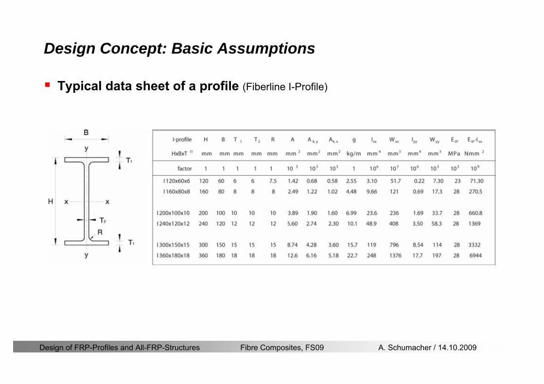
Design of FRP-Profiles and All-FRP-Structures Fibre Composites FS09 A Schumacher 14102009
Design Concept Basic Assumptions
Typical data sheet of a profile (Fiberline I-Profile)
Design of FRP-Profiles and All-FRP-Structures Fibre Composites FS09 A Schumacher 14102009
Bending Beam
Design of FRP-Profiles and All-FRP-Structures Fibre Composites FS09 A Schumacher 14102009
Bending Beam Design of hellip
Calculate bending moments Md and shear forces Qd acting on the profile using the partial coefficient (SIA 260 261)
Ultimate limit state
Bending
Shear
Ak hellip relevant shear area
d max d max 0max
M MW Wy z b
mzy
fσ γ
⎛ ⎞⎜ ⎟⎜ ⎟⎜ ⎟⎜ ⎟⎝ ⎠
deg= + le
d maxmax
kyAy
m
Q fττ γ= le
Design of FRP-Profiles and All-FRP-Structures Fibre Composites FS09 A Schumacher 14102009
Bending Beam Design of hellip
Serviceability limit state
Deflection limit
hellip typically selected between 200 and 400given by SIA 261 or the building owner
hellip calculated including shear deformations
Vibrations
Light-weighted and lsquosoftrsquo structures are susceptible to vibrations (traffic wind the movement of people hellip)
max 1wL αlt
α
maxw
Design of FRP-Profiles and All-FRP-Structures Fibre Composites FS09 A Schumacher 14102009
Bending Beam Timoshenko Theory
Pultruded profiles have a low shear modulus rarr shear deformation must be taken into account
Several bending theories have been published for beams
Euler-Bernoulli theory (1702)
Timoshenko theory (1968)
Higher order beam theory
A simply supported beam with a symmetric cross-section is discussed
Design of FRP-Profiles and All-FRP-Structures Fibre Composites FS09 A Schumacher 14102009
Bending Beam Timoshenko Theory
Cross-sections planeand perpendicular
1 degree of freedom
w
Cross-sections plane butNOT perpendicular
2 degrees of freedom
w and ψ
Cross-sections do NOTremain plane
3+ degrees of freedom
w ψ and hellip
Design of FRP-Profiles and All-FRP-Structures Fibre Composites FS09 A Schumacher 14102009
Bending Beam Euler vs Timoshenko Theory
Kinematic relationships
( )( )
( )
2 0
x x
y
xx xx
yxxy
u y w xu w x
u y w xxuu
y x
ε
ε
=minus sdot=
part= =minus sdotpartpartpart= + =
part part
( )( )
( )
2 ( ) ( )
x
y
xx x
yxxy x
u y xu w x
u y xxuu x w xy x
ψ
ε ψ
ε ψ
=minus sdot=
part= =minus sdotpartpartpart= + =minus +
part part
Hookrsquos law
0degE and G 2x x xy xyσ ε τ ε= sdot = sdot
z0deg E Iz x xxQS
M y dydz wσ= minus sdot sdot = sdot sdotintint
( )
z0deg E I
z x xQS
y xQS
M y dydz
Q dydz w GA
σ ψ
κ τ ψ κ
= minus sdot sdot = sdot
= sdot = minus sdot sdot
intint
intint
Design of FRP-Profiles and All-FRP-Structures Fibre Composites FS09 A Schumacher 14102009
Bending Beam Euler vs Timoshenko Theory
Equilibrium
Solution for the simply supported beam (distributed load)
In a first approximation the deflections are calculated by direct integration of
z0deg
( ) E IxxM xw = sdot
( )( )z0deg
( ) E I 0x
x
xx x
xx x
q x w GAw GA
QM Q
ψ κψ ψ κ
minus minus sdot sdot
sdot + minus sdot sdot
=minus =
= =minus
Equilibrium on an infinitesimal beam element
Coupled second order differential equation
21 1( ) (0) 0 and ( ) 02 2
M x qLx qx w w L= minus = =
( )3 2 3
0deg z
( ) 224 E Iqxw x L Lx x= sdot minus +sdot sdot
2
0deg z
1 1 1E I 2 2xxw qLx qx⎛ ⎞= minus⎜ ⎟sdot ⎝ ⎠
(0) 0 and ( ) 0(0) 0 (0) 0 and ( ) 0 ( ) 0 x x
w w LM M L Lψ ψ
= == rarr = = rarr =
Functions4 3 2
1 2 3 4 53 2
1 2 3 4
( )
( )
w x A x A x A x A x A
x B x B x B x Bψ
= + + + +
= + + +
Design of FRP-Profiles and All-FRP-Structures Fibre Composites FS09 A Schumacher 14102009
Put in and solve for the coefficients rarr
Bending Beam Euler vs Timoshenko Theory
Use the boundary conditions and the second differential eq to calculate A1 ndash A5
( )0deg z E I 0xx xw GAψ ψ κsdot + minus sdot sdot =
1 01 1 3 3
2 02 2 4 4
24 E I4 2GA
6 E I3 GA
z
z
AB A B A
AB A B A
κ
κ
deg
deg
sdot= minus = minus minus
sdotsdot
= minus = minus minussdot
( ) ( )( )2 2
0
( )2 GA 24 E Iz
qx L x L Lx xqx L xw x
κ deg
minus + minusminus= +
sdot sdot sdot
Deflection at midspan
4
0
52 384 E Iz
qLLw⎛ ⎞⎜ ⎟⎝ ⎠
deg
sdot= sdot4 2
0
52 384 E I 8 GAz
qL q LLw κ⎛ ⎞ +⎜ ⎟⎝ ⎠
deg
sdot sdot= sdot sdot sdot
Design of FRP-Profiles and All-FRP-Structures Fibre Composites FS09 A Schumacher 14102009
General expression for the total beam deflection as a sum of the deflection due to bending and shear
GAxf
IExfxwz sdot+=
deg κ)()()( 2
0
1
Cantilever beam
Simply supported
Concentrated load (P)
Uniformly distr load (q)
Concentrated load (P)
Uniformly distr load (q)
Beam )( max1 wf
3845 4qLsdot
48
3PL
8
4qL
3
3PL
)( max1 wf
8
2qL
4PL
2
2qL
PL
)( maxwx
2L
2L
L
L
Bending Beam Euler vs Timoshenko Theory
Design of FRP-Profiles and All-FRP-Structures Fibre Composites FS09 A Schumacher 14102009
Bending Beam Euler vs Timoshenko Theory
Example influence of the shear deformation
Profile 300 x 150 mm I-beam
Load uniformly distributed
General rule of thumbfor GFRP beams withspandepth gt 25 sheardeformation can beignored
Design of FRP-Profiles and All-FRP-Structures Fibre Composites FS09 A Schumacher 14102009
Bending Beam Example
Choose an appropriate Profile for the following specifications
1 Deflections and loading
=
=
==
1300 rarr wmax=001 mwmaxL
10 kNmqdser
13 kNmqduls
30 mL
max
4 2
0
5384 E I 8 GA
d ser d serz
q L q Lw κ+
deg
sdot sdot= sdot sdot sdot
2
maxz8 2 I
d ulsq L hσ sdot= sdot
maxky
12 Ad ulsq L
τ sdot=
Design of FRP-Profiles and All-FRP-Structures Fibre Composites FS09 A Schumacher 14102009
Bending Beam Example
2 Find a profile with sufficient bending stiffness
Shear deformations are neglected in a first step
rarr from specification table choose I 240x120x12 rarr
3 Check the bending and shear stresses
6 24
0 max
1054 10 Nm5
E I 384d ser
zq Lwdeg = sdot
sdotsdotge
6 20 1369 10 NmE Izdeg = sdot
2
maxz
358 MPa8 2 Id ulsq L hσ sdot= =sdot
max
ky
1 71 MPa2 Ad ulsq L
τ sdot= =
0 185 MPab df degle =
20 MPadfτle =
Design of FRP-Profiles and All-FRP-Structures Fibre Composites FS09 A Schumacher 14102009
Bending Beam Example
m10398384
5 32
0
4
maxminus
deg
sdot=sdotsdotsdot
+sdot
sdot=
GALq
IELq
w serd
z
serd
κ
4 Check deflection (including shear deformation)
5 Remarks
The design of GFRP-profiles is mostly driven by serviceability criteria
Start the design iteration procedure using the maximal deflection criterion
max 001 mwle =
m10198384
5 32
0
4
maxminus
deg
sdot=sdot
sdot+
sdotsdot
=web
serd
z
serd
GALq
IELq
w
(77 mm) (16 mm)
Design of FRP-Profiles and All-FRP-Structures Fibre Composites FS09 A Schumacher 14102009
Bending Beam Stability problems
Lateral-torsional bucklingFlange (compressive) displace laterally to the transverse load direction
Torsional stiffness is too low (especially for open section profiles)
Theoretical calculations or design measuresrarr see eg LP Kollaacuter 2003
Mechanics of composite structuresExample
Compressive flanges are kept in place by connection to the bridge deck
Design of FRP-Profiles and All-FRP-Structures Fibre Composites FS09 A Schumacher 14102009
Bending Beam Stability problems
Flange (compressive) displaces in the direction of the transverse load
Low bending stiffness perpendicular to the pultrusion direction
Weak fiber mats
Local buckling of walls due to in-plane compression
Local buckling of walls due to in-plane shear
Web crushing and web buckling in transverse direction
Design of FRP-Profiles and All-FRP-Structures Fibre Composites FS09 A Schumacher 14102009
Axial Members
Design of FRP-Profiles and All-FRP-Structures Fibre Composites FS09 A Schumacher 14102009
Axial Members Tension
Ultimate limit state under axial tension Nd
Serviceability limit state
Remark The critical aspect of axial members in tension are neither the serviceability nor the ultimate limit state Critical is the load transfer to the GFRP profile
0NdA
tm
fγ
degle
0deg
N LE Axδ sdot= sdot
Design of FRP-Profiles and All-FRP-Structures Fibre Composites FS09 A Schumacher 14102009
Axial Members Compression
Ultimate limit state under axial compression Nd
hellip maximal compressive load
hellip Euler load
hellip Buckling length for columns
hellip coefficient for Youngrsquos modulus = 13
cc
Euler
FNd F1 N
le+
c0degC
A fF
mγsdot
=
20
Euler 2
Nm E k
E IL
πγ
degsdot sdot=
sdot
kL
m Eγ
Design of FRP-Profiles and All-FRP-Structures Fibre Composites FS09 A Schumacher 14102009
Axial Members Compression
The influence of shear deformation should be considered but in the most cases the influence will be small (less than 5)
Local buckling should be considered for short columns
For more information on the various buckling modes and effects rarr see LP Kollaacuter 2003 Mechanics of composite structures
Global buckling Local buckling
Design of FRP-Profiles and All-FRP-Structures Fibre Composites FS09 A Schumacher 14102009
Connections
Design of FRP-Profiles and All-FRP-Structures Fibre Composites FS09 A Schumacher 14102009
Connections Introduction
Design of FRP-Profiles and All-FRP-Structures Fibre Composites FS09 A Schumacher 14102009
Connections Introduction
(from Eurocomp Design Code 1996)
Design of FRP-Profiles and All-FRP-Structures Fibre Composites FS09 A Schumacher 14102009
Connections Bolted joints
Bolts = Stress concentration in the profile and the bolt
It is necessary to ensure that the bolts and the profilecan withstand this concentrated local stress compression
It is necessary to ensure that the region surroundinga group of bolts will not be torn out of the profile
Basic failure modesin bolted shearconnections
bolt shear failure
Design of FRP-Profiles and All-FRP-Structures Fibre Composites FS09 A Schumacher 14102009
Connections Bolted joints
The design procedure is comparable to the one for steel connections but since there exist no standard GFRP material rarr each manufacturer has its own design rules for bolted joints
IMPORTANT REMARKS
The direction of pultrusion and the direction of the force is RELEVANT(anisotropic material)
Use stainless or galvanised steel
Do not cut threads in the composite material
Use screws with shafts
Design of FRP-Profiles and All-FRP-Structures Fibre Composites FS09 A Schumacher 14102009
Calculation of load bearing capacity of bolts
Shear in longitudinal direction (0deg)
Shear in transverse direction (90deg)
Tensile force
Minimum distances
Connections Bolted joints (Fiberline recommendations)
Design of FRP-Profiles and All-FRP-Structures Fibre Composites FS09 A Schumacher 14102009
Joint capacity tables available for shear and tension
m
150 MPa( 13)B d
d tP γsdot sdot=
=
Shear in longitudinal direction 0deg
m
70 MPa( 13)B d
d tP γsdot sdot=
=
Shear in transverse direction 90deg
Connections Bolted joints (Fiberline recommendations)
Design of FRP-Profiles and All-FRP-Structures Fibre Composites FS09 A Schumacher 14102009
Bolted connection in shear eg shear in longitudinal direction
Connections Bolted joints (Fiberline recommendations)
γmPBolt le dt720 MPaγmPBolt le dt240 MPa
γmPBolt le dt240 MPa γmPBolt le dt240 MPaγmPBolt le dt150 MPa
Design of FRP-Profiles and All-FRP-Structures Fibre Composites FS09 A Schumacher 14102009
Bolted connections in tension
Static conditions
Bolt Tearing of bolt in threaded cross-section
Laminate Shear fracture at rim of washer
Geometry and strength
Diameter of washer2d
Tensile strength of bolt hellipfyk
Shear strength of laminatehellipfτ
Thickness of laminatet
Stress area of the boltAs
Diameter of the boltd
s ykd m
A fP γ
sdotle
2d m
d t fP τπγ
sdot sdot sdot sdotle
Connections Bolted joints (Fiberline recommendations)
Design of FRP-Profiles and All-FRP-Structures Fibre Composites FS09 A Schumacher 14102009
Connections Bonded joints
Using an adhesive agent for joining profiles can have advantages
Easy to use easy to make aesthetic joints
Typically more rigid than bolted joints
Glued joints subjected to dynamic loads are good
But be careful hellipAdhesive agents have properties that depend on time temperature humidity hellip
Failure in glued joints takes place suddenly (brittle behaviour)
The load-bearing capacity is not proportional to the area which is glued
The design of bonded joints may be based onAnalytical models for plate-to-plate connections (see Eurocomp 1996 Design Code)
Design guidelines supplemented by testing
Finite element analysis
Design of FRP-Profiles and All-FRP-Structures Fibre Composites FS09 A Schumacher 14102009
Connections Bonded joints
A bonded joint has the following three primary failure modes
adhesive failure
cohesive failure of adhesive
cohesive failure of adherend
The design of any bonded joint shall satisfy the following conditions
allowable shear stress in the adhesive is not exceeded
allowable tensile (peel) stress in the adhesive is not exceeded
allowable through-thickness tensile stress of the adhesive is not exceeded
allowable in-plane shear stress of the adherend should not be exceeded
The calculation of the stresses has to be done very carefully Often calculations are supplemented by testing
Design of FRP-Profiles and All-FRP-Structures Fibre Composites FS09 A Schumacher 14102009
Connections Bonded joints
Different types of bonded joint configurations
Research on bonded joints for structuralapplications
Design of FRP-Profiles and All-FRP-Structures Fibre Composites FS09 A Schumacher 14102009
Connections Other joints
Brackets for assembly (Fiberline)
Custom pultruded connections
Design of FRP-Profiles and All-FRP-Structures Fibre Composites FS09 A Schumacher 14102009
GFRP Some final remarks
Perpendicular to the direction of pultrusion the material is WEAK and SOFTrarr avoid such loadings if possible
In order to use pultruded GFRP-profiles economically the design must be done in a clever way eg for bridges the railings should be used as part of the load-bearing structure
GFRP structures are very light rarr vibration problems may occur
Design of FRP-Profiles and All-FRP-Structures Fibre Composites FS09 A Schumacher 14102009
Bending Beam
Design of FRP-Profiles and All-FRP-Structures Fibre Composites FS09 A Schumacher 14102009
Bending Beam Design of hellip
Calculate bending moments Md and shear forces Qd acting on the profile using the partial coefficient (SIA 260 261)
Ultimate limit state
Bending
Shear
Ak hellip relevant shear area
d max d max 0max
M MW Wy z b
mzy
fσ γ
⎛ ⎞⎜ ⎟⎜ ⎟⎜ ⎟⎜ ⎟⎝ ⎠
deg= + le
d maxmax
kyAy
m
Q fττ γ= le
Design of FRP-Profiles and All-FRP-Structures Fibre Composites FS09 A Schumacher 14102009
Bending Beam Design of hellip
Serviceability limit state
Deflection limit
hellip typically selected between 200 and 400given by SIA 261 or the building owner
hellip calculated including shear deformations
Vibrations
Light-weighted and lsquosoftrsquo structures are susceptible to vibrations (traffic wind the movement of people hellip)
max 1wL αlt
α
maxw
Design of FRP-Profiles and All-FRP-Structures Fibre Composites FS09 A Schumacher 14102009
Bending Beam Timoshenko Theory
Pultruded profiles have a low shear modulus rarr shear deformation must be taken into account
Several bending theories have been published for beams
Euler-Bernoulli theory (1702)
Timoshenko theory (1968)
Higher order beam theory
A simply supported beam with a symmetric cross-section is discussed
Design of FRP-Profiles and All-FRP-Structures Fibre Composites FS09 A Schumacher 14102009
Bending Beam Timoshenko Theory
Cross-sections planeand perpendicular
1 degree of freedom
w
Cross-sections plane butNOT perpendicular
2 degrees of freedom
w and ψ
Cross-sections do NOTremain plane
3+ degrees of freedom
w ψ and hellip
Design of FRP-Profiles and All-FRP-Structures Fibre Composites FS09 A Schumacher 14102009
Bending Beam Euler vs Timoshenko Theory
Kinematic relationships
( )( )
( )
2 0
x x
y
xx xx
yxxy
u y w xu w x
u y w xxuu
y x
ε
ε
=minus sdot=
part= =minus sdotpartpartpart= + =
part part
( )( )
( )
2 ( ) ( )
x
y
xx x
yxxy x
u y xu w x
u y xxuu x w xy x
ψ
ε ψ
ε ψ
=minus sdot=
part= =minus sdotpartpartpart= + =minus +
part part
Hookrsquos law
0degE and G 2x x xy xyσ ε τ ε= sdot = sdot
z0deg E Iz x xxQS
M y dydz wσ= minus sdot sdot = sdot sdotintint
( )
z0deg E I
z x xQS
y xQS
M y dydz
Q dydz w GA
σ ψ
κ τ ψ κ
= minus sdot sdot = sdot
= sdot = minus sdot sdot
intint
intint
Design of FRP-Profiles and All-FRP-Structures Fibre Composites FS09 A Schumacher 14102009
Bending Beam Euler vs Timoshenko Theory
Equilibrium
Solution for the simply supported beam (distributed load)
In a first approximation the deflections are calculated by direct integration of
z0deg
( ) E IxxM xw = sdot
( )( )z0deg
( ) E I 0x
x
xx x
xx x
q x w GAw GA
QM Q
ψ κψ ψ κ
minus minus sdot sdot
sdot + minus sdot sdot
=minus =
= =minus
Equilibrium on an infinitesimal beam element
Coupled second order differential equation
21 1( ) (0) 0 and ( ) 02 2
M x qLx qx w w L= minus = =
( )3 2 3
0deg z
( ) 224 E Iqxw x L Lx x= sdot minus +sdot sdot
2
0deg z
1 1 1E I 2 2xxw qLx qx⎛ ⎞= minus⎜ ⎟sdot ⎝ ⎠
(0) 0 and ( ) 0(0) 0 (0) 0 and ( ) 0 ( ) 0 x x
w w LM M L Lψ ψ
= == rarr = = rarr =
Functions4 3 2
1 2 3 4 53 2
1 2 3 4
( )
( )
w x A x A x A x A x A
x B x B x B x Bψ
= + + + +
= + + +
Design of FRP-Profiles and All-FRP-Structures Fibre Composites FS09 A Schumacher 14102009
Put in and solve for the coefficients rarr
Bending Beam Euler vs Timoshenko Theory
Use the boundary conditions and the second differential eq to calculate A1 ndash A5
( )0deg z E I 0xx xw GAψ ψ κsdot + minus sdot sdot =
1 01 1 3 3
2 02 2 4 4
24 E I4 2GA
6 E I3 GA
z
z
AB A B A
AB A B A
κ
κ
deg
deg
sdot= minus = minus minus
sdotsdot
= minus = minus minussdot
( ) ( )( )2 2
0
( )2 GA 24 E Iz
qx L x L Lx xqx L xw x
κ deg
minus + minusminus= +
sdot sdot sdot
Deflection at midspan
4
0
52 384 E Iz
qLLw⎛ ⎞⎜ ⎟⎝ ⎠
deg
sdot= sdot4 2
0
52 384 E I 8 GAz
qL q LLw κ⎛ ⎞ +⎜ ⎟⎝ ⎠
deg
sdot sdot= sdot sdot sdot
Design of FRP-Profiles and All-FRP-Structures Fibre Composites FS09 A Schumacher 14102009
General expression for the total beam deflection as a sum of the deflection due to bending and shear
GAxf
IExfxwz sdot+=
deg κ)()()( 2
0
1
Cantilever beam
Simply supported
Concentrated load (P)
Uniformly distr load (q)
Concentrated load (P)
Uniformly distr load (q)
Beam )( max1 wf
3845 4qLsdot
48
3PL
8
4qL
3
3PL
)( max1 wf
8
2qL
4PL
2
2qL
PL
)( maxwx
2L
2L
L
L
Bending Beam Euler vs Timoshenko Theory
Design of FRP-Profiles and All-FRP-Structures Fibre Composites FS09 A Schumacher 14102009
Bending Beam Euler vs Timoshenko Theory
Example influence of the shear deformation
Profile 300 x 150 mm I-beam
Load uniformly distributed
General rule of thumbfor GFRP beams withspandepth gt 25 sheardeformation can beignored
Design of FRP-Profiles and All-FRP-Structures Fibre Composites FS09 A Schumacher 14102009
Bending Beam Example
Choose an appropriate Profile for the following specifications
1 Deflections and loading
=
=
==
1300 rarr wmax=001 mwmaxL
10 kNmqdser
13 kNmqduls
30 mL
max
4 2
0
5384 E I 8 GA
d ser d serz
q L q Lw κ+
deg
sdot sdot= sdot sdot sdot
2
maxz8 2 I
d ulsq L hσ sdot= sdot
maxky
12 Ad ulsq L
τ sdot=
Design of FRP-Profiles and All-FRP-Structures Fibre Composites FS09 A Schumacher 14102009
Bending Beam Example
2 Find a profile with sufficient bending stiffness
Shear deformations are neglected in a first step
rarr from specification table choose I 240x120x12 rarr
3 Check the bending and shear stresses
6 24
0 max
1054 10 Nm5
E I 384d ser
zq Lwdeg = sdot
sdotsdotge
6 20 1369 10 NmE Izdeg = sdot
2
maxz
358 MPa8 2 Id ulsq L hσ sdot= =sdot
max
ky
1 71 MPa2 Ad ulsq L
τ sdot= =
0 185 MPab df degle =
20 MPadfτle =
Design of FRP-Profiles and All-FRP-Structures Fibre Composites FS09 A Schumacher 14102009
Bending Beam Example
m10398384
5 32
0
4
maxminus
deg
sdot=sdotsdotsdot
+sdot
sdot=
GALq
IELq
w serd
z
serd
κ
4 Check deflection (including shear deformation)
5 Remarks
The design of GFRP-profiles is mostly driven by serviceability criteria
Start the design iteration procedure using the maximal deflection criterion
max 001 mwle =
m10198384
5 32
0
4
maxminus
deg
sdot=sdot
sdot+
sdotsdot
=web
serd
z
serd
GALq
IELq
w
(77 mm) (16 mm)
Design of FRP-Profiles and All-FRP-Structures Fibre Composites FS09 A Schumacher 14102009
Bending Beam Stability problems
Lateral-torsional bucklingFlange (compressive) displace laterally to the transverse load direction
Torsional stiffness is too low (especially for open section profiles)
Theoretical calculations or design measuresrarr see eg LP Kollaacuter 2003
Mechanics of composite structuresExample
Compressive flanges are kept in place by connection to the bridge deck
Design of FRP-Profiles and All-FRP-Structures Fibre Composites FS09 A Schumacher 14102009
Bending Beam Stability problems
Flange (compressive) displaces in the direction of the transverse load
Low bending stiffness perpendicular to the pultrusion direction
Weak fiber mats
Local buckling of walls due to in-plane compression
Local buckling of walls due to in-plane shear
Web crushing and web buckling in transverse direction
Design of FRP-Profiles and All-FRP-Structures Fibre Composites FS09 A Schumacher 14102009
Axial Members
Design of FRP-Profiles and All-FRP-Structures Fibre Composites FS09 A Schumacher 14102009
Axial Members Tension
Ultimate limit state under axial tension Nd
Serviceability limit state
Remark The critical aspect of axial members in tension are neither the serviceability nor the ultimate limit state Critical is the load transfer to the GFRP profile
0NdA
tm
fγ
degle
0deg
N LE Axδ sdot= sdot
Design of FRP-Profiles and All-FRP-Structures Fibre Composites FS09 A Schumacher 14102009
Axial Members Compression
Ultimate limit state under axial compression Nd
hellip maximal compressive load
hellip Euler load
hellip Buckling length for columns
hellip coefficient for Youngrsquos modulus = 13
cc
Euler
FNd F1 N
le+
c0degC
A fF
mγsdot
=
20
Euler 2
Nm E k
E IL
πγ
degsdot sdot=
sdot
kL
m Eγ
Design of FRP-Profiles and All-FRP-Structures Fibre Composites FS09 A Schumacher 14102009
Axial Members Compression
The influence of shear deformation should be considered but in the most cases the influence will be small (less than 5)
Local buckling should be considered for short columns
For more information on the various buckling modes and effects rarr see LP Kollaacuter 2003 Mechanics of composite structures
Global buckling Local buckling
Design of FRP-Profiles and All-FRP-Structures Fibre Composites FS09 A Schumacher 14102009
Connections
Design of FRP-Profiles and All-FRP-Structures Fibre Composites FS09 A Schumacher 14102009
Connections Introduction
Design of FRP-Profiles and All-FRP-Structures Fibre Composites FS09 A Schumacher 14102009
Connections Introduction
(from Eurocomp Design Code 1996)
Design of FRP-Profiles and All-FRP-Structures Fibre Composites FS09 A Schumacher 14102009
Connections Bolted joints
Bolts = Stress concentration in the profile and the bolt
It is necessary to ensure that the bolts and the profilecan withstand this concentrated local stress compression
It is necessary to ensure that the region surroundinga group of bolts will not be torn out of the profile
Basic failure modesin bolted shearconnections
bolt shear failure
Design of FRP-Profiles and All-FRP-Structures Fibre Composites FS09 A Schumacher 14102009
Connections Bolted joints
The design procedure is comparable to the one for steel connections but since there exist no standard GFRP material rarr each manufacturer has its own design rules for bolted joints
IMPORTANT REMARKS
The direction of pultrusion and the direction of the force is RELEVANT(anisotropic material)
Use stainless or galvanised steel
Do not cut threads in the composite material
Use screws with shafts
Design of FRP-Profiles and All-FRP-Structures Fibre Composites FS09 A Schumacher 14102009
Calculation of load bearing capacity of bolts
Shear in longitudinal direction (0deg)
Shear in transverse direction (90deg)
Tensile force
Minimum distances
Connections Bolted joints (Fiberline recommendations)
Design of FRP-Profiles and All-FRP-Structures Fibre Composites FS09 A Schumacher 14102009
Joint capacity tables available for shear and tension
m
150 MPa( 13)B d
d tP γsdot sdot=
=
Shear in longitudinal direction 0deg
m
70 MPa( 13)B d
d tP γsdot sdot=
=
Shear in transverse direction 90deg
Connections Bolted joints (Fiberline recommendations)
Design of FRP-Profiles and All-FRP-Structures Fibre Composites FS09 A Schumacher 14102009
Bolted connection in shear eg shear in longitudinal direction
Connections Bolted joints (Fiberline recommendations)
γmPBolt le dt720 MPaγmPBolt le dt240 MPa
γmPBolt le dt240 MPa γmPBolt le dt240 MPaγmPBolt le dt150 MPa
Design of FRP-Profiles and All-FRP-Structures Fibre Composites FS09 A Schumacher 14102009
Bolted connections in tension
Static conditions
Bolt Tearing of bolt in threaded cross-section
Laminate Shear fracture at rim of washer
Geometry and strength
Diameter of washer2d
Tensile strength of bolt hellipfyk
Shear strength of laminatehellipfτ
Thickness of laminatet
Stress area of the boltAs
Diameter of the boltd
s ykd m
A fP γ
sdotle
2d m
d t fP τπγ
sdot sdot sdot sdotle
Connections Bolted joints (Fiberline recommendations)
Design of FRP-Profiles and All-FRP-Structures Fibre Composites FS09 A Schumacher 14102009
Connections Bonded joints
Using an adhesive agent for joining profiles can have advantages
Easy to use easy to make aesthetic joints
Typically more rigid than bolted joints
Glued joints subjected to dynamic loads are good
But be careful hellipAdhesive agents have properties that depend on time temperature humidity hellip
Failure in glued joints takes place suddenly (brittle behaviour)
The load-bearing capacity is not proportional to the area which is glued
The design of bonded joints may be based onAnalytical models for plate-to-plate connections (see Eurocomp 1996 Design Code)
Design guidelines supplemented by testing
Finite element analysis
Design of FRP-Profiles and All-FRP-Structures Fibre Composites FS09 A Schumacher 14102009
Connections Bonded joints
A bonded joint has the following three primary failure modes
adhesive failure
cohesive failure of adhesive
cohesive failure of adherend
The design of any bonded joint shall satisfy the following conditions
allowable shear stress in the adhesive is not exceeded
allowable tensile (peel) stress in the adhesive is not exceeded
allowable through-thickness tensile stress of the adhesive is not exceeded
allowable in-plane shear stress of the adherend should not be exceeded
The calculation of the stresses has to be done very carefully Often calculations are supplemented by testing
Design of FRP-Profiles and All-FRP-Structures Fibre Composites FS09 A Schumacher 14102009
Connections Bonded joints
Different types of bonded joint configurations
Research on bonded joints for structuralapplications
Design of FRP-Profiles and All-FRP-Structures Fibre Composites FS09 A Schumacher 14102009
Connections Other joints
Brackets for assembly (Fiberline)
Custom pultruded connections
Design of FRP-Profiles and All-FRP-Structures Fibre Composites FS09 A Schumacher 14102009
GFRP Some final remarks
Perpendicular to the direction of pultrusion the material is WEAK and SOFTrarr avoid such loadings if possible
In order to use pultruded GFRP-profiles economically the design must be done in a clever way eg for bridges the railings should be used as part of the load-bearing structure
GFRP structures are very light rarr vibration problems may occur
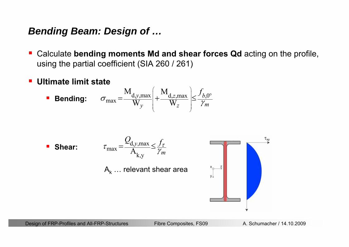
Design of FRP-Profiles and All-FRP-Structures Fibre Composites FS09 A Schumacher 14102009
Bending Beam Design of hellip
Calculate bending moments Md and shear forces Qd acting on the profile using the partial coefficient (SIA 260 261)
Ultimate limit state
Bending
Shear
Ak hellip relevant shear area
d max d max 0max
M MW Wy z b
mzy
fσ γ
⎛ ⎞⎜ ⎟⎜ ⎟⎜ ⎟⎜ ⎟⎝ ⎠
deg= + le
d maxmax
kyAy
m
Q fττ γ= le
Design of FRP-Profiles and All-FRP-Structures Fibre Composites FS09 A Schumacher 14102009
Bending Beam Design of hellip
Serviceability limit state
Deflection limit
hellip typically selected between 200 and 400given by SIA 261 or the building owner
hellip calculated including shear deformations
Vibrations
Light-weighted and lsquosoftrsquo structures are susceptible to vibrations (traffic wind the movement of people hellip)
max 1wL αlt
α
maxw
Design of FRP-Profiles and All-FRP-Structures Fibre Composites FS09 A Schumacher 14102009
Bending Beam Timoshenko Theory
Pultruded profiles have a low shear modulus rarr shear deformation must be taken into account
Several bending theories have been published for beams
Euler-Bernoulli theory (1702)
Timoshenko theory (1968)
Higher order beam theory
A simply supported beam with a symmetric cross-section is discussed
Design of FRP-Profiles and All-FRP-Structures Fibre Composites FS09 A Schumacher 14102009
Bending Beam Timoshenko Theory
Cross-sections planeand perpendicular
1 degree of freedom
w
Cross-sections plane butNOT perpendicular
2 degrees of freedom
w and ψ
Cross-sections do NOTremain plane
3+ degrees of freedom
w ψ and hellip
Design of FRP-Profiles and All-FRP-Structures Fibre Composites FS09 A Schumacher 14102009
Bending Beam Euler vs Timoshenko Theory
Kinematic relationships
( )( )
( )
2 0
x x
y
xx xx
yxxy
u y w xu w x
u y w xxuu
y x
ε
ε
=minus sdot=
part= =minus sdotpartpartpart= + =
part part
( )( )
( )
2 ( ) ( )
x
y
xx x
yxxy x
u y xu w x
u y xxuu x w xy x
ψ
ε ψ
ε ψ
=minus sdot=
part= =minus sdotpartpartpart= + =minus +
part part
Hookrsquos law
0degE and G 2x x xy xyσ ε τ ε= sdot = sdot
z0deg E Iz x xxQS
M y dydz wσ= minus sdot sdot = sdot sdotintint
( )
z0deg E I
z x xQS
y xQS
M y dydz
Q dydz w GA
σ ψ
κ τ ψ κ
= minus sdot sdot = sdot
= sdot = minus sdot sdot
intint
intint
Design of FRP-Profiles and All-FRP-Structures Fibre Composites FS09 A Schumacher 14102009
Bending Beam Euler vs Timoshenko Theory
Equilibrium
Solution for the simply supported beam (distributed load)
In a first approximation the deflections are calculated by direct integration of
z0deg
( ) E IxxM xw = sdot
( )( )z0deg
( ) E I 0x
x
xx x
xx x
q x w GAw GA
QM Q
ψ κψ ψ κ
minus minus sdot sdot
sdot + minus sdot sdot
=minus =
= =minus
Equilibrium on an infinitesimal beam element
Coupled second order differential equation
21 1( ) (0) 0 and ( ) 02 2
M x qLx qx w w L= minus = =
( )3 2 3
0deg z
( ) 224 E Iqxw x L Lx x= sdot minus +sdot sdot
2
0deg z
1 1 1E I 2 2xxw qLx qx⎛ ⎞= minus⎜ ⎟sdot ⎝ ⎠
(0) 0 and ( ) 0(0) 0 (0) 0 and ( ) 0 ( ) 0 x x
w w LM M L Lψ ψ
= == rarr = = rarr =
Functions4 3 2
1 2 3 4 53 2
1 2 3 4
( )
( )
w x A x A x A x A x A
x B x B x B x Bψ
= + + + +
= + + +
Design of FRP-Profiles and All-FRP-Structures Fibre Composites FS09 A Schumacher 14102009
Put in and solve for the coefficients rarr
Bending Beam Euler vs Timoshenko Theory
Use the boundary conditions and the second differential eq to calculate A1 ndash A5
( )0deg z E I 0xx xw GAψ ψ κsdot + minus sdot sdot =
1 01 1 3 3
2 02 2 4 4
24 E I4 2GA
6 E I3 GA
z
z
AB A B A
AB A B A
κ
κ
deg
deg
sdot= minus = minus minus
sdotsdot
= minus = minus minussdot
( ) ( )( )2 2
0
( )2 GA 24 E Iz
qx L x L Lx xqx L xw x
κ deg
minus + minusminus= +
sdot sdot sdot
Deflection at midspan
4
0
52 384 E Iz
qLLw⎛ ⎞⎜ ⎟⎝ ⎠
deg
sdot= sdot4 2
0
52 384 E I 8 GAz
qL q LLw κ⎛ ⎞ +⎜ ⎟⎝ ⎠
deg
sdot sdot= sdot sdot sdot
Design of FRP-Profiles and All-FRP-Structures Fibre Composites FS09 A Schumacher 14102009
General expression for the total beam deflection as a sum of the deflection due to bending and shear
GAxf
IExfxwz sdot+=
deg κ)()()( 2
0
1
Cantilever beam
Simply supported
Concentrated load (P)
Uniformly distr load (q)
Concentrated load (P)
Uniformly distr load (q)
Beam )( max1 wf
3845 4qLsdot
48
3PL
8
4qL
3
3PL
)( max1 wf
8
2qL
4PL
2
2qL
PL
)( maxwx
2L
2L
L
L
Bending Beam Euler vs Timoshenko Theory
Design of FRP-Profiles and All-FRP-Structures Fibre Composites FS09 A Schumacher 14102009
Bending Beam Euler vs Timoshenko Theory
Example influence of the shear deformation
Profile 300 x 150 mm I-beam
Load uniformly distributed
General rule of thumbfor GFRP beams withspandepth gt 25 sheardeformation can beignored
Design of FRP-Profiles and All-FRP-Structures Fibre Composites FS09 A Schumacher 14102009
Bending Beam Example
Choose an appropriate Profile for the following specifications
1 Deflections and loading
=
=
==
1300 rarr wmax=001 mwmaxL
10 kNmqdser
13 kNmqduls
30 mL
max
4 2
0
5384 E I 8 GA
d ser d serz
q L q Lw κ+
deg
sdot sdot= sdot sdot sdot
2
maxz8 2 I
d ulsq L hσ sdot= sdot
maxky
12 Ad ulsq L
τ sdot=
Design of FRP-Profiles and All-FRP-Structures Fibre Composites FS09 A Schumacher 14102009
Bending Beam Example
2 Find a profile with sufficient bending stiffness
Shear deformations are neglected in a first step
rarr from specification table choose I 240x120x12 rarr
3 Check the bending and shear stresses
6 24
0 max
1054 10 Nm5
E I 384d ser
zq Lwdeg = sdot
sdotsdotge
6 20 1369 10 NmE Izdeg = sdot
2
maxz
358 MPa8 2 Id ulsq L hσ sdot= =sdot
max
ky
1 71 MPa2 Ad ulsq L
τ sdot= =
0 185 MPab df degle =
20 MPadfτle =
Design of FRP-Profiles and All-FRP-Structures Fibre Composites FS09 A Schumacher 14102009
Bending Beam Example
m10398384
5 32
0
4
maxminus
deg
sdot=sdotsdotsdot
+sdot
sdot=
GALq
IELq
w serd
z
serd
κ
4 Check deflection (including shear deformation)
5 Remarks
The design of GFRP-profiles is mostly driven by serviceability criteria
Start the design iteration procedure using the maximal deflection criterion
max 001 mwle =
m10198384
5 32
0
4
maxminus
deg
sdot=sdot
sdot+
sdotsdot
=web
serd
z
serd
GALq
IELq
w
(77 mm) (16 mm)
Design of FRP-Profiles and All-FRP-Structures Fibre Composites FS09 A Schumacher 14102009
Bending Beam Stability problems
Lateral-torsional bucklingFlange (compressive) displace laterally to the transverse load direction
Torsional stiffness is too low (especially for open section profiles)
Theoretical calculations or design measuresrarr see eg LP Kollaacuter 2003
Mechanics of composite structuresExample
Compressive flanges are kept in place by connection to the bridge deck
Design of FRP-Profiles and All-FRP-Structures Fibre Composites FS09 A Schumacher 14102009
Bending Beam Stability problems
Flange (compressive) displaces in the direction of the transverse load
Low bending stiffness perpendicular to the pultrusion direction
Weak fiber mats
Local buckling of walls due to in-plane compression
Local buckling of walls due to in-plane shear
Web crushing and web buckling in transverse direction
Design of FRP-Profiles and All-FRP-Structures Fibre Composites FS09 A Schumacher 14102009
Axial Members
Design of FRP-Profiles and All-FRP-Structures Fibre Composites FS09 A Schumacher 14102009
Axial Members Tension
Ultimate limit state under axial tension Nd
Serviceability limit state
Remark The critical aspect of axial members in tension are neither the serviceability nor the ultimate limit state Critical is the load transfer to the GFRP profile
0NdA
tm
fγ
degle
0deg
N LE Axδ sdot= sdot
Design of FRP-Profiles and All-FRP-Structures Fibre Composites FS09 A Schumacher 14102009
Axial Members Compression
Ultimate limit state under axial compression Nd
hellip maximal compressive load
hellip Euler load
hellip Buckling length for columns
hellip coefficient for Youngrsquos modulus = 13
cc
Euler
FNd F1 N
le+
c0degC
A fF
mγsdot
=
20
Euler 2
Nm E k
E IL
πγ
degsdot sdot=
sdot
kL
m Eγ
Design of FRP-Profiles and All-FRP-Structures Fibre Composites FS09 A Schumacher 14102009
Axial Members Compression
The influence of shear deformation should be considered but in the most cases the influence will be small (less than 5)
Local buckling should be considered for short columns
For more information on the various buckling modes and effects rarr see LP Kollaacuter 2003 Mechanics of composite structures
Global buckling Local buckling
Design of FRP-Profiles and All-FRP-Structures Fibre Composites FS09 A Schumacher 14102009
Connections
Design of FRP-Profiles and All-FRP-Structures Fibre Composites FS09 A Schumacher 14102009
Connections Introduction
Design of FRP-Profiles and All-FRP-Structures Fibre Composites FS09 A Schumacher 14102009
Connections Introduction
(from Eurocomp Design Code 1996)
Design of FRP-Profiles and All-FRP-Structures Fibre Composites FS09 A Schumacher 14102009
Connections Bolted joints
Bolts = Stress concentration in the profile and the bolt
It is necessary to ensure that the bolts and the profilecan withstand this concentrated local stress compression
It is necessary to ensure that the region surroundinga group of bolts will not be torn out of the profile
Basic failure modesin bolted shearconnections
bolt shear failure
Design of FRP-Profiles and All-FRP-Structures Fibre Composites FS09 A Schumacher 14102009
Connections Bolted joints
The design procedure is comparable to the one for steel connections but since there exist no standard GFRP material rarr each manufacturer has its own design rules for bolted joints
IMPORTANT REMARKS
The direction of pultrusion and the direction of the force is RELEVANT(anisotropic material)
Use stainless or galvanised steel
Do not cut threads in the composite material
Use screws with shafts
Design of FRP-Profiles and All-FRP-Structures Fibre Composites FS09 A Schumacher 14102009
Calculation of load bearing capacity of bolts
Shear in longitudinal direction (0deg)
Shear in transverse direction (90deg)
Tensile force
Minimum distances
Connections Bolted joints (Fiberline recommendations)
Design of FRP-Profiles and All-FRP-Structures Fibre Composites FS09 A Schumacher 14102009
Joint capacity tables available for shear and tension
m
150 MPa( 13)B d
d tP γsdot sdot=
=
Shear in longitudinal direction 0deg
m
70 MPa( 13)B d
d tP γsdot sdot=
=
Shear in transverse direction 90deg
Connections Bolted joints (Fiberline recommendations)
Design of FRP-Profiles and All-FRP-Structures Fibre Composites FS09 A Schumacher 14102009
Bolted connection in shear eg shear in longitudinal direction
Connections Bolted joints (Fiberline recommendations)
γmPBolt le dt720 MPaγmPBolt le dt240 MPa
γmPBolt le dt240 MPa γmPBolt le dt240 MPaγmPBolt le dt150 MPa
Design of FRP-Profiles and All-FRP-Structures Fibre Composites FS09 A Schumacher 14102009
Bolted connections in tension
Static conditions
Bolt Tearing of bolt in threaded cross-section
Laminate Shear fracture at rim of washer
Geometry and strength
Diameter of washer2d
Tensile strength of bolt hellipfyk
Shear strength of laminatehellipfτ
Thickness of laminatet
Stress area of the boltAs
Diameter of the boltd
s ykd m
A fP γ
sdotle
2d m
d t fP τπγ
sdot sdot sdot sdotle
Connections Bolted joints (Fiberline recommendations)
Design of FRP-Profiles and All-FRP-Structures Fibre Composites FS09 A Schumacher 14102009
Connections Bonded joints
Using an adhesive agent for joining profiles can have advantages
Easy to use easy to make aesthetic joints
Typically more rigid than bolted joints
Glued joints subjected to dynamic loads are good
But be careful hellipAdhesive agents have properties that depend on time temperature humidity hellip
Failure in glued joints takes place suddenly (brittle behaviour)
The load-bearing capacity is not proportional to the area which is glued
The design of bonded joints may be based onAnalytical models for plate-to-plate connections (see Eurocomp 1996 Design Code)
Design guidelines supplemented by testing
Finite element analysis
Design of FRP-Profiles and All-FRP-Structures Fibre Composites FS09 A Schumacher 14102009
Connections Bonded joints
A bonded joint has the following three primary failure modes
adhesive failure
cohesive failure of adhesive
cohesive failure of adherend
The design of any bonded joint shall satisfy the following conditions
allowable shear stress in the adhesive is not exceeded
allowable tensile (peel) stress in the adhesive is not exceeded
allowable through-thickness tensile stress of the adhesive is not exceeded
allowable in-plane shear stress of the adherend should not be exceeded
The calculation of the stresses has to be done very carefully Often calculations are supplemented by testing
Design of FRP-Profiles and All-FRP-Structures Fibre Composites FS09 A Schumacher 14102009
Connections Bonded joints
Different types of bonded joint configurations
Research on bonded joints for structuralapplications
Design of FRP-Profiles and All-FRP-Structures Fibre Composites FS09 A Schumacher 14102009
Connections Other joints
Brackets for assembly (Fiberline)
Custom pultruded connections
Design of FRP-Profiles and All-FRP-Structures Fibre Composites FS09 A Schumacher 14102009
GFRP Some final remarks
Perpendicular to the direction of pultrusion the material is WEAK and SOFTrarr avoid such loadings if possible
In order to use pultruded GFRP-profiles economically the design must be done in a clever way eg for bridges the railings should be used as part of the load-bearing structure
GFRP structures are very light rarr vibration problems may occur
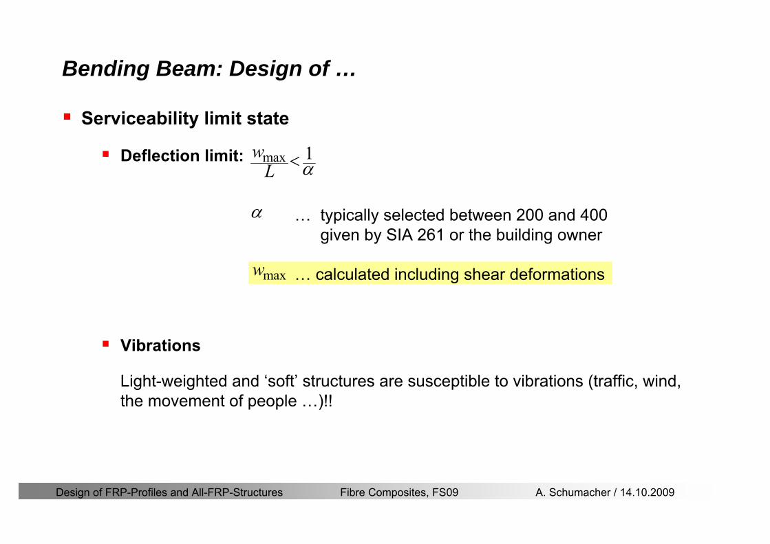
Design of FRP-Profiles and All-FRP-Structures Fibre Composites FS09 A Schumacher 14102009
Bending Beam Design of hellip
Serviceability limit state
Deflection limit
hellip typically selected between 200 and 400given by SIA 261 or the building owner
hellip calculated including shear deformations
Vibrations
Light-weighted and lsquosoftrsquo structures are susceptible to vibrations (traffic wind the movement of people hellip)
max 1wL αlt
α
maxw
Design of FRP-Profiles and All-FRP-Structures Fibre Composites FS09 A Schumacher 14102009
Bending Beam Timoshenko Theory
Pultruded profiles have a low shear modulus rarr shear deformation must be taken into account
Several bending theories have been published for beams
Euler-Bernoulli theory (1702)
Timoshenko theory (1968)
Higher order beam theory
A simply supported beam with a symmetric cross-section is discussed
Design of FRP-Profiles and All-FRP-Structures Fibre Composites FS09 A Schumacher 14102009
Bending Beam Timoshenko Theory
Cross-sections planeand perpendicular
1 degree of freedom
w
Cross-sections plane butNOT perpendicular
2 degrees of freedom
w and ψ
Cross-sections do NOTremain plane
3+ degrees of freedom
w ψ and hellip
Design of FRP-Profiles and All-FRP-Structures Fibre Composites FS09 A Schumacher 14102009
Bending Beam Euler vs Timoshenko Theory
Kinematic relationships
( )( )
( )
2 0
x x
y
xx xx
yxxy
u y w xu w x
u y w xxuu
y x
ε
ε
=minus sdot=
part= =minus sdotpartpartpart= + =
part part
( )( )
( )
2 ( ) ( )
x
y
xx x
yxxy x
u y xu w x
u y xxuu x w xy x
ψ
ε ψ
ε ψ
=minus sdot=
part= =minus sdotpartpartpart= + =minus +
part part
Hookrsquos law
0degE and G 2x x xy xyσ ε τ ε= sdot = sdot
z0deg E Iz x xxQS
M y dydz wσ= minus sdot sdot = sdot sdotintint
( )
z0deg E I
z x xQS
y xQS
M y dydz
Q dydz w GA
σ ψ
κ τ ψ κ
= minus sdot sdot = sdot
= sdot = minus sdot sdot
intint
intint
Design of FRP-Profiles and All-FRP-Structures Fibre Composites FS09 A Schumacher 14102009
Bending Beam Euler vs Timoshenko Theory
Equilibrium
Solution for the simply supported beam (distributed load)
In a first approximation the deflections are calculated by direct integration of
z0deg
( ) E IxxM xw = sdot
( )( )z0deg
( ) E I 0x
x
xx x
xx x
q x w GAw GA
QM Q
ψ κψ ψ κ
minus minus sdot sdot
sdot + minus sdot sdot
=minus =
= =minus
Equilibrium on an infinitesimal beam element
Coupled second order differential equation
21 1( ) (0) 0 and ( ) 02 2
M x qLx qx w w L= minus = =
( )3 2 3
0deg z
( ) 224 E Iqxw x L Lx x= sdot minus +sdot sdot
2
0deg z
1 1 1E I 2 2xxw qLx qx⎛ ⎞= minus⎜ ⎟sdot ⎝ ⎠
(0) 0 and ( ) 0(0) 0 (0) 0 and ( ) 0 ( ) 0 x x
w w LM M L Lψ ψ
= == rarr = = rarr =
Functions4 3 2
1 2 3 4 53 2
1 2 3 4
( )
( )
w x A x A x A x A x A
x B x B x B x Bψ
= + + + +
= + + +
Design of FRP-Profiles and All-FRP-Structures Fibre Composites FS09 A Schumacher 14102009
Put in and solve for the coefficients rarr
Bending Beam Euler vs Timoshenko Theory
Use the boundary conditions and the second differential eq to calculate A1 ndash A5
( )0deg z E I 0xx xw GAψ ψ κsdot + minus sdot sdot =
1 01 1 3 3
2 02 2 4 4
24 E I4 2GA
6 E I3 GA
z
z
AB A B A
AB A B A
κ
κ
deg
deg
sdot= minus = minus minus
sdotsdot
= minus = minus minussdot
( ) ( )( )2 2
0
( )2 GA 24 E Iz
qx L x L Lx xqx L xw x
κ deg
minus + minusminus= +
sdot sdot sdot
Deflection at midspan
4
0
52 384 E Iz
qLLw⎛ ⎞⎜ ⎟⎝ ⎠
deg
sdot= sdot4 2
0
52 384 E I 8 GAz
qL q LLw κ⎛ ⎞ +⎜ ⎟⎝ ⎠
deg
sdot sdot= sdot sdot sdot
Design of FRP-Profiles and All-FRP-Structures Fibre Composites FS09 A Schumacher 14102009
General expression for the total beam deflection as a sum of the deflection due to bending and shear
GAxf
IExfxwz sdot+=
deg κ)()()( 2
0
1
Cantilever beam
Simply supported
Concentrated load (P)
Uniformly distr load (q)
Concentrated load (P)
Uniformly distr load (q)
Beam )( max1 wf
3845 4qLsdot
48
3PL
8
4qL
3
3PL
)( max1 wf
8
2qL
4PL
2
2qL
PL
)( maxwx
2L
2L
L
L
Bending Beam Euler vs Timoshenko Theory
Design of FRP-Profiles and All-FRP-Structures Fibre Composites FS09 A Schumacher 14102009
Bending Beam Euler vs Timoshenko Theory
Example influence of the shear deformation
Profile 300 x 150 mm I-beam
Load uniformly distributed
General rule of thumbfor GFRP beams withspandepth gt 25 sheardeformation can beignored
Design of FRP-Profiles and All-FRP-Structures Fibre Composites FS09 A Schumacher 14102009
Bending Beam Example
Choose an appropriate Profile for the following specifications
1 Deflections and loading
=
=
==
1300 rarr wmax=001 mwmaxL
10 kNmqdser
13 kNmqduls
30 mL
max
4 2
0
5384 E I 8 GA
d ser d serz
q L q Lw κ+
deg
sdot sdot= sdot sdot sdot
2
maxz8 2 I
d ulsq L hσ sdot= sdot
maxky
12 Ad ulsq L
τ sdot=
Design of FRP-Profiles and All-FRP-Structures Fibre Composites FS09 A Schumacher 14102009
Bending Beam Example
2 Find a profile with sufficient bending stiffness
Shear deformations are neglected in a first step
rarr from specification table choose I 240x120x12 rarr
3 Check the bending and shear stresses
6 24
0 max
1054 10 Nm5
E I 384d ser
zq Lwdeg = sdot
sdotsdotge
6 20 1369 10 NmE Izdeg = sdot
2
maxz
358 MPa8 2 Id ulsq L hσ sdot= =sdot
max
ky
1 71 MPa2 Ad ulsq L
τ sdot= =
0 185 MPab df degle =
20 MPadfτle =
Design of FRP-Profiles and All-FRP-Structures Fibre Composites FS09 A Schumacher 14102009
Bending Beam Example
m10398384
5 32
0
4
maxminus
deg
sdot=sdotsdotsdot
+sdot
sdot=
GALq
IELq
w serd
z
serd
κ
4 Check deflection (including shear deformation)
5 Remarks
The design of GFRP-profiles is mostly driven by serviceability criteria
Start the design iteration procedure using the maximal deflection criterion
max 001 mwle =
m10198384
5 32
0
4
maxminus
deg
sdot=sdot
sdot+
sdotsdot
=web
serd
z
serd
GALq
IELq
w
(77 mm) (16 mm)
Design of FRP-Profiles and All-FRP-Structures Fibre Composites FS09 A Schumacher 14102009
Bending Beam Stability problems
Lateral-torsional bucklingFlange (compressive) displace laterally to the transverse load direction
Torsional stiffness is too low (especially for open section profiles)
Theoretical calculations or design measuresrarr see eg LP Kollaacuter 2003
Mechanics of composite structuresExample
Compressive flanges are kept in place by connection to the bridge deck
Design of FRP-Profiles and All-FRP-Structures Fibre Composites FS09 A Schumacher 14102009
Bending Beam Stability problems
Flange (compressive) displaces in the direction of the transverse load
Low bending stiffness perpendicular to the pultrusion direction
Weak fiber mats
Local buckling of walls due to in-plane compression
Local buckling of walls due to in-plane shear
Web crushing and web buckling in transverse direction
Design of FRP-Profiles and All-FRP-Structures Fibre Composites FS09 A Schumacher 14102009
Axial Members
Design of FRP-Profiles and All-FRP-Structures Fibre Composites FS09 A Schumacher 14102009
Axial Members Tension
Ultimate limit state under axial tension Nd
Serviceability limit state
Remark The critical aspect of axial members in tension are neither the serviceability nor the ultimate limit state Critical is the load transfer to the GFRP profile
0NdA
tm
fγ
degle
0deg
N LE Axδ sdot= sdot
Design of FRP-Profiles and All-FRP-Structures Fibre Composites FS09 A Schumacher 14102009
Axial Members Compression
Ultimate limit state under axial compression Nd
hellip maximal compressive load
hellip Euler load
hellip Buckling length for columns
hellip coefficient for Youngrsquos modulus = 13
cc
Euler
FNd F1 N
le+
c0degC
A fF
mγsdot
=
20
Euler 2
Nm E k
E IL
πγ
degsdot sdot=
sdot
kL
m Eγ
Design of FRP-Profiles and All-FRP-Structures Fibre Composites FS09 A Schumacher 14102009
Axial Members Compression
The influence of shear deformation should be considered but in the most cases the influence will be small (less than 5)
Local buckling should be considered for short columns
For more information on the various buckling modes and effects rarr see LP Kollaacuter 2003 Mechanics of composite structures
Global buckling Local buckling
Design of FRP-Profiles and All-FRP-Structures Fibre Composites FS09 A Schumacher 14102009
Connections
Design of FRP-Profiles and All-FRP-Structures Fibre Composites FS09 A Schumacher 14102009
Connections Introduction
Design of FRP-Profiles and All-FRP-Structures Fibre Composites FS09 A Schumacher 14102009
Connections Introduction
(from Eurocomp Design Code 1996)
Design of FRP-Profiles and All-FRP-Structures Fibre Composites FS09 A Schumacher 14102009
Connections Bolted joints
Bolts = Stress concentration in the profile and the bolt
It is necessary to ensure that the bolts and the profilecan withstand this concentrated local stress compression
It is necessary to ensure that the region surroundinga group of bolts will not be torn out of the profile
Basic failure modesin bolted shearconnections
bolt shear failure
Design of FRP-Profiles and All-FRP-Structures Fibre Composites FS09 A Schumacher 14102009
Connections Bolted joints
The design procedure is comparable to the one for steel connections but since there exist no standard GFRP material rarr each manufacturer has its own design rules for bolted joints
IMPORTANT REMARKS
The direction of pultrusion and the direction of the force is RELEVANT(anisotropic material)
Use stainless or galvanised steel
Do not cut threads in the composite material
Use screws with shafts
Design of FRP-Profiles and All-FRP-Structures Fibre Composites FS09 A Schumacher 14102009
Calculation of load bearing capacity of bolts
Shear in longitudinal direction (0deg)
Shear in transverse direction (90deg)
Tensile force
Minimum distances
Connections Bolted joints (Fiberline recommendations)
Design of FRP-Profiles and All-FRP-Structures Fibre Composites FS09 A Schumacher 14102009
Joint capacity tables available for shear and tension
m
150 MPa( 13)B d
d tP γsdot sdot=
=
Shear in longitudinal direction 0deg
m
70 MPa( 13)B d
d tP γsdot sdot=
=
Shear in transverse direction 90deg
Connections Bolted joints (Fiberline recommendations)
Design of FRP-Profiles and All-FRP-Structures Fibre Composites FS09 A Schumacher 14102009
Bolted connection in shear eg shear in longitudinal direction
Connections Bolted joints (Fiberline recommendations)
γmPBolt le dt720 MPaγmPBolt le dt240 MPa
γmPBolt le dt240 MPa γmPBolt le dt240 MPaγmPBolt le dt150 MPa
Design of FRP-Profiles and All-FRP-Structures Fibre Composites FS09 A Schumacher 14102009
Bolted connections in tension
Static conditions
Bolt Tearing of bolt in threaded cross-section
Laminate Shear fracture at rim of washer
Geometry and strength
Diameter of washer2d
Tensile strength of bolt hellipfyk
Shear strength of laminatehellipfτ
Thickness of laminatet
Stress area of the boltAs
Diameter of the boltd
s ykd m
A fP γ
sdotle
2d m
d t fP τπγ
sdot sdot sdot sdotle
Connections Bolted joints (Fiberline recommendations)
Design of FRP-Profiles and All-FRP-Structures Fibre Composites FS09 A Schumacher 14102009
Connections Bonded joints
Using an adhesive agent for joining profiles can have advantages
Easy to use easy to make aesthetic joints
Typically more rigid than bolted joints
Glued joints subjected to dynamic loads are good
But be careful hellipAdhesive agents have properties that depend on time temperature humidity hellip
Failure in glued joints takes place suddenly (brittle behaviour)
The load-bearing capacity is not proportional to the area which is glued
The design of bonded joints may be based onAnalytical models for plate-to-plate connections (see Eurocomp 1996 Design Code)
Design guidelines supplemented by testing
Finite element analysis
Design of FRP-Profiles and All-FRP-Structures Fibre Composites FS09 A Schumacher 14102009
Connections Bonded joints
A bonded joint has the following three primary failure modes
adhesive failure
cohesive failure of adhesive
cohesive failure of adherend
The design of any bonded joint shall satisfy the following conditions
allowable shear stress in the adhesive is not exceeded
allowable tensile (peel) stress in the adhesive is not exceeded
allowable through-thickness tensile stress of the adhesive is not exceeded
allowable in-plane shear stress of the adherend should not be exceeded
The calculation of the stresses has to be done very carefully Often calculations are supplemented by testing
Design of FRP-Profiles and All-FRP-Structures Fibre Composites FS09 A Schumacher 14102009
Connections Bonded joints
Different types of bonded joint configurations
Research on bonded joints for structuralapplications
Design of FRP-Profiles and All-FRP-Structures Fibre Composites FS09 A Schumacher 14102009
Connections Other joints
Brackets for assembly (Fiberline)
Custom pultruded connections
Design of FRP-Profiles and All-FRP-Structures Fibre Composites FS09 A Schumacher 14102009
GFRP Some final remarks
Perpendicular to the direction of pultrusion the material is WEAK and SOFTrarr avoid such loadings if possible
In order to use pultruded GFRP-profiles economically the design must be done in a clever way eg for bridges the railings should be used as part of the load-bearing structure
GFRP structures are very light rarr vibration problems may occur
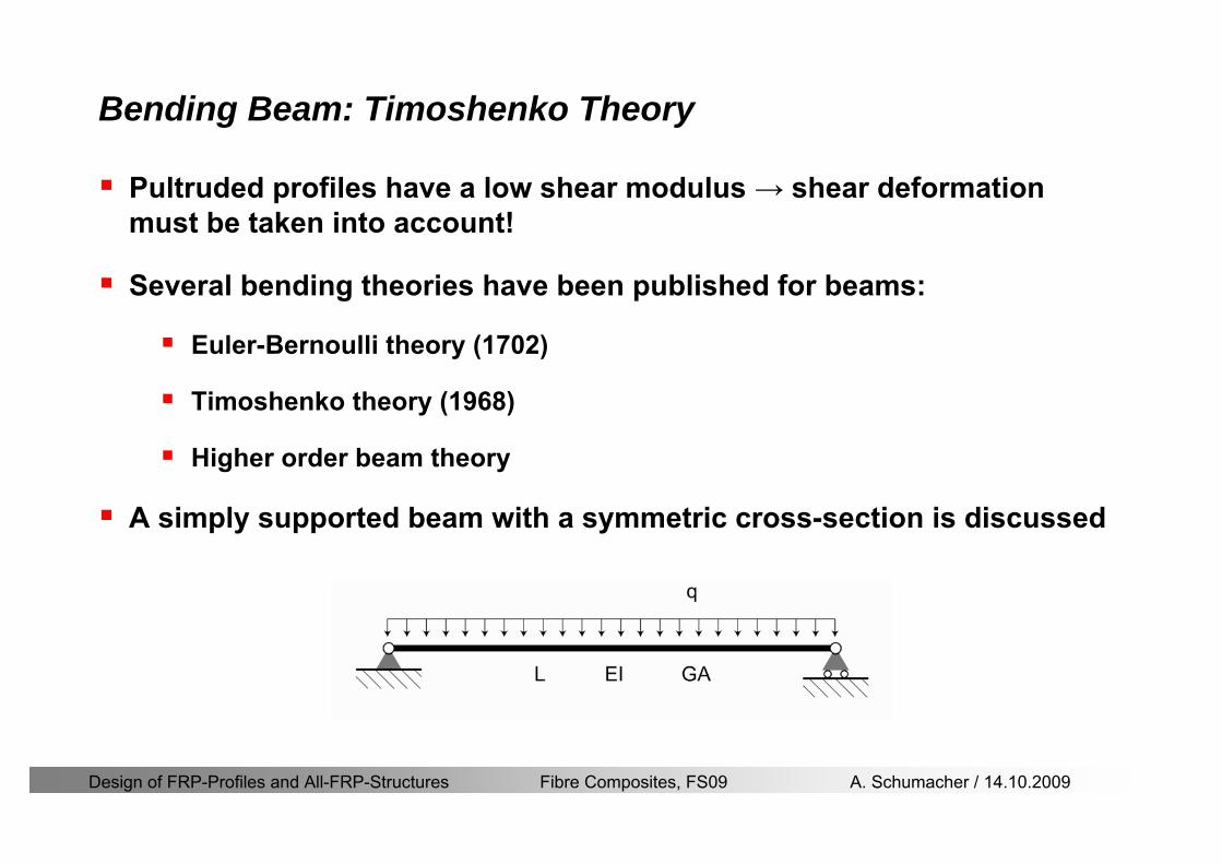
Design of FRP-Profiles and All-FRP-Structures Fibre Composites FS09 A Schumacher 14102009
Bending Beam Timoshenko Theory
Pultruded profiles have a low shear modulus rarr shear deformation must be taken into account
Several bending theories have been published for beams
Euler-Bernoulli theory (1702)
Timoshenko theory (1968)
Higher order beam theory
A simply supported beam with a symmetric cross-section is discussed
Design of FRP-Profiles and All-FRP-Structures Fibre Composites FS09 A Schumacher 14102009
Bending Beam Timoshenko Theory
Cross-sections planeand perpendicular
1 degree of freedom
w
Cross-sections plane butNOT perpendicular
2 degrees of freedom
w and ψ
Cross-sections do NOTremain plane
3+ degrees of freedom
w ψ and hellip
Design of FRP-Profiles and All-FRP-Structures Fibre Composites FS09 A Schumacher 14102009
Bending Beam Euler vs Timoshenko Theory
Kinematic relationships
( )( )
( )
2 0
x x
y
xx xx
yxxy
u y w xu w x
u y w xxuu
y x
ε
ε
=minus sdot=
part= =minus sdotpartpartpart= + =
part part
( )( )
( )
2 ( ) ( )
x
y
xx x
yxxy x
u y xu w x
u y xxuu x w xy x
ψ
ε ψ
ε ψ
=minus sdot=
part= =minus sdotpartpartpart= + =minus +
part part
Hookrsquos law
0degE and G 2x x xy xyσ ε τ ε= sdot = sdot
z0deg E Iz x xxQS
M y dydz wσ= minus sdot sdot = sdot sdotintint
( )
z0deg E I
z x xQS
y xQS
M y dydz
Q dydz w GA
σ ψ
κ τ ψ κ
= minus sdot sdot = sdot
= sdot = minus sdot sdot
intint
intint
Design of FRP-Profiles and All-FRP-Structures Fibre Composites FS09 A Schumacher 14102009
Bending Beam Euler vs Timoshenko Theory
Equilibrium
Solution for the simply supported beam (distributed load)
In a first approximation the deflections are calculated by direct integration of
z0deg
( ) E IxxM xw = sdot
( )( )z0deg
( ) E I 0x
x
xx x
xx x
q x w GAw GA
QM Q
ψ κψ ψ κ
minus minus sdot sdot
sdot + minus sdot sdot
=minus =
= =minus
Equilibrium on an infinitesimal beam element
Coupled second order differential equation
21 1( ) (0) 0 and ( ) 02 2
M x qLx qx w w L= minus = =
( )3 2 3
0deg z
( ) 224 E Iqxw x L Lx x= sdot minus +sdot sdot
2
0deg z
1 1 1E I 2 2xxw qLx qx⎛ ⎞= minus⎜ ⎟sdot ⎝ ⎠
(0) 0 and ( ) 0(0) 0 (0) 0 and ( ) 0 ( ) 0 x x
w w LM M L Lψ ψ
= == rarr = = rarr =
Functions4 3 2
1 2 3 4 53 2
1 2 3 4
( )
( )
w x A x A x A x A x A
x B x B x B x Bψ
= + + + +
= + + +
Design of FRP-Profiles and All-FRP-Structures Fibre Composites FS09 A Schumacher 14102009
Put in and solve for the coefficients rarr
Bending Beam Euler vs Timoshenko Theory
Use the boundary conditions and the second differential eq to calculate A1 ndash A5
( )0deg z E I 0xx xw GAψ ψ κsdot + minus sdot sdot =
1 01 1 3 3
2 02 2 4 4
24 E I4 2GA
6 E I3 GA
z
z
AB A B A
AB A B A
κ
κ
deg
deg
sdot= minus = minus minus
sdotsdot
= minus = minus minussdot
( ) ( )( )2 2
0
( )2 GA 24 E Iz
qx L x L Lx xqx L xw x
κ deg
minus + minusminus= +
sdot sdot sdot
Deflection at midspan
4
0
52 384 E Iz
qLLw⎛ ⎞⎜ ⎟⎝ ⎠
deg
sdot= sdot4 2
0
52 384 E I 8 GAz
qL q LLw κ⎛ ⎞ +⎜ ⎟⎝ ⎠
deg
sdot sdot= sdot sdot sdot
Design of FRP-Profiles and All-FRP-Structures Fibre Composites FS09 A Schumacher 14102009
General expression for the total beam deflection as a sum of the deflection due to bending and shear
GAxf
IExfxwz sdot+=
deg κ)()()( 2
0
1
Cantilever beam
Simply supported
Concentrated load (P)
Uniformly distr load (q)
Concentrated load (P)
Uniformly distr load (q)
Beam )( max1 wf
3845 4qLsdot
48
3PL
8
4qL
3
3PL
)( max1 wf
8
2qL
4PL
2
2qL
PL
)( maxwx
2L
2L
L
L
Bending Beam Euler vs Timoshenko Theory
Design of FRP-Profiles and All-FRP-Structures Fibre Composites FS09 A Schumacher 14102009
Bending Beam Euler vs Timoshenko Theory
Example influence of the shear deformation
Profile 300 x 150 mm I-beam
Load uniformly distributed
General rule of thumbfor GFRP beams withspandepth gt 25 sheardeformation can beignored
Design of FRP-Profiles and All-FRP-Structures Fibre Composites FS09 A Schumacher 14102009
Bending Beam Example
Choose an appropriate Profile for the following specifications
1 Deflections and loading
=
=
==
1300 rarr wmax=001 mwmaxL
10 kNmqdser
13 kNmqduls
30 mL
max
4 2
0
5384 E I 8 GA
d ser d serz
q L q Lw κ+
deg
sdot sdot= sdot sdot sdot
2
maxz8 2 I
d ulsq L hσ sdot= sdot
maxky
12 Ad ulsq L
τ sdot=
Design of FRP-Profiles and All-FRP-Structures Fibre Composites FS09 A Schumacher 14102009
Bending Beam Example
2 Find a profile with sufficient bending stiffness
Shear deformations are neglected in a first step
rarr from specification table choose I 240x120x12 rarr
3 Check the bending and shear stresses
6 24
0 max
1054 10 Nm5
E I 384d ser
zq Lwdeg = sdot
sdotsdotge
6 20 1369 10 NmE Izdeg = sdot
2
maxz
358 MPa8 2 Id ulsq L hσ sdot= =sdot
max
ky
1 71 MPa2 Ad ulsq L
τ sdot= =
0 185 MPab df degle =
20 MPadfτle =
Design of FRP-Profiles and All-FRP-Structures Fibre Composites FS09 A Schumacher 14102009
Bending Beam Example
m10398384
5 32
0
4
maxminus
deg
sdot=sdotsdotsdot
+sdot
sdot=
GALq
IELq
w serd
z
serd
κ
4 Check deflection (including shear deformation)
5 Remarks
The design of GFRP-profiles is mostly driven by serviceability criteria
Start the design iteration procedure using the maximal deflection criterion
max 001 mwle =
m10198384
5 32
0
4
maxminus
deg
sdot=sdot
sdot+
sdotsdot
=web
serd
z
serd
GALq
IELq
w
(77 mm) (16 mm)
Design of FRP-Profiles and All-FRP-Structures Fibre Composites FS09 A Schumacher 14102009
Bending Beam Stability problems
Lateral-torsional bucklingFlange (compressive) displace laterally to the transverse load direction
Torsional stiffness is too low (especially for open section profiles)
Theoretical calculations or design measuresrarr see eg LP Kollaacuter 2003
Mechanics of composite structuresExample
Compressive flanges are kept in place by connection to the bridge deck
Design of FRP-Profiles and All-FRP-Structures Fibre Composites FS09 A Schumacher 14102009
Bending Beam Stability problems
Flange (compressive) displaces in the direction of the transverse load
Low bending stiffness perpendicular to the pultrusion direction
Weak fiber mats
Local buckling of walls due to in-plane compression
Local buckling of walls due to in-plane shear
Web crushing and web buckling in transverse direction
Design of FRP-Profiles and All-FRP-Structures Fibre Composites FS09 A Schumacher 14102009
Axial Members
Design of FRP-Profiles and All-FRP-Structures Fibre Composites FS09 A Schumacher 14102009
Axial Members Tension
Ultimate limit state under axial tension Nd
Serviceability limit state
Remark The critical aspect of axial members in tension are neither the serviceability nor the ultimate limit state Critical is the load transfer to the GFRP profile
0NdA
tm
fγ
degle
0deg
N LE Axδ sdot= sdot
Design of FRP-Profiles and All-FRP-Structures Fibre Composites FS09 A Schumacher 14102009
Axial Members Compression
Ultimate limit state under axial compression Nd
hellip maximal compressive load
hellip Euler load
hellip Buckling length for columns
hellip coefficient for Youngrsquos modulus = 13
cc
Euler
FNd F1 N
le+
c0degC
A fF
mγsdot
=
20
Euler 2
Nm E k
E IL
πγ
degsdot sdot=
sdot
kL
m Eγ
Design of FRP-Profiles and All-FRP-Structures Fibre Composites FS09 A Schumacher 14102009
Axial Members Compression
The influence of shear deformation should be considered but in the most cases the influence will be small (less than 5)
Local buckling should be considered for short columns
For more information on the various buckling modes and effects rarr see LP Kollaacuter 2003 Mechanics of composite structures
Global buckling Local buckling
Design of FRP-Profiles and All-FRP-Structures Fibre Composites FS09 A Schumacher 14102009
Connections
Design of FRP-Profiles and All-FRP-Structures Fibre Composites FS09 A Schumacher 14102009
Connections Introduction
Design of FRP-Profiles and All-FRP-Structures Fibre Composites FS09 A Schumacher 14102009
Connections Introduction
(from Eurocomp Design Code 1996)
Design of FRP-Profiles and All-FRP-Structures Fibre Composites FS09 A Schumacher 14102009
Connections Bolted joints
Bolts = Stress concentration in the profile and the bolt
It is necessary to ensure that the bolts and the profilecan withstand this concentrated local stress compression
It is necessary to ensure that the region surroundinga group of bolts will not be torn out of the profile
Basic failure modesin bolted shearconnections
bolt shear failure
Design of FRP-Profiles and All-FRP-Structures Fibre Composites FS09 A Schumacher 14102009
Connections Bolted joints
The design procedure is comparable to the one for steel connections but since there exist no standard GFRP material rarr each manufacturer has its own design rules for bolted joints
IMPORTANT REMARKS
The direction of pultrusion and the direction of the force is RELEVANT(anisotropic material)
Use stainless or galvanised steel
Do not cut threads in the composite material
Use screws with shafts
Design of FRP-Profiles and All-FRP-Structures Fibre Composites FS09 A Schumacher 14102009
Calculation of load bearing capacity of bolts
Shear in longitudinal direction (0deg)
Shear in transverse direction (90deg)
Tensile force
Minimum distances
Connections Bolted joints (Fiberline recommendations)
Design of FRP-Profiles and All-FRP-Structures Fibre Composites FS09 A Schumacher 14102009
Joint capacity tables available for shear and tension
m
150 MPa( 13)B d
d tP γsdot sdot=
=
Shear in longitudinal direction 0deg
m
70 MPa( 13)B d
d tP γsdot sdot=
=
Shear in transverse direction 90deg
Connections Bolted joints (Fiberline recommendations)
Design of FRP-Profiles and All-FRP-Structures Fibre Composites FS09 A Schumacher 14102009
Bolted connection in shear eg shear in longitudinal direction
Connections Bolted joints (Fiberline recommendations)
γmPBolt le dt720 MPaγmPBolt le dt240 MPa
γmPBolt le dt240 MPa γmPBolt le dt240 MPaγmPBolt le dt150 MPa
Design of FRP-Profiles and All-FRP-Structures Fibre Composites FS09 A Schumacher 14102009
Bolted connections in tension
Static conditions
Bolt Tearing of bolt in threaded cross-section
Laminate Shear fracture at rim of washer
Geometry and strength
Diameter of washer2d
Tensile strength of bolt hellipfyk
Shear strength of laminatehellipfτ
Thickness of laminatet
Stress area of the boltAs
Diameter of the boltd
s ykd m
A fP γ
sdotle
2d m
d t fP τπγ
sdot sdot sdot sdotle
Connections Bolted joints (Fiberline recommendations)
Design of FRP-Profiles and All-FRP-Structures Fibre Composites FS09 A Schumacher 14102009
Connections Bonded joints
Using an adhesive agent for joining profiles can have advantages
Easy to use easy to make aesthetic joints
Typically more rigid than bolted joints
Glued joints subjected to dynamic loads are good
But be careful hellipAdhesive agents have properties that depend on time temperature humidity hellip
Failure in glued joints takes place suddenly (brittle behaviour)
The load-bearing capacity is not proportional to the area which is glued
The design of bonded joints may be based onAnalytical models for plate-to-plate connections (see Eurocomp 1996 Design Code)
Design guidelines supplemented by testing
Finite element analysis
Design of FRP-Profiles and All-FRP-Structures Fibre Composites FS09 A Schumacher 14102009
Connections Bonded joints
A bonded joint has the following three primary failure modes
adhesive failure
cohesive failure of adhesive
cohesive failure of adherend
The design of any bonded joint shall satisfy the following conditions
allowable shear stress in the adhesive is not exceeded
allowable tensile (peel) stress in the adhesive is not exceeded
allowable through-thickness tensile stress of the adhesive is not exceeded
allowable in-plane shear stress of the adherend should not be exceeded
The calculation of the stresses has to be done very carefully Often calculations are supplemented by testing
Design of FRP-Profiles and All-FRP-Structures Fibre Composites FS09 A Schumacher 14102009
Connections Bonded joints
Different types of bonded joint configurations
Research on bonded joints for structuralapplications
Design of FRP-Profiles and All-FRP-Structures Fibre Composites FS09 A Schumacher 14102009
Connections Other joints
Brackets for assembly (Fiberline)
Custom pultruded connections
Design of FRP-Profiles and All-FRP-Structures Fibre Composites FS09 A Schumacher 14102009
GFRP Some final remarks
Perpendicular to the direction of pultrusion the material is WEAK and SOFTrarr avoid such loadings if possible
In order to use pultruded GFRP-profiles economically the design must be done in a clever way eg for bridges the railings should be used as part of the load-bearing structure
GFRP structures are very light rarr vibration problems may occur
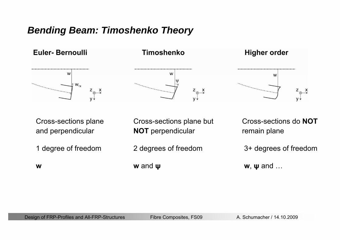
Design of FRP-Profiles and All-FRP-Structures Fibre Composites FS09 A Schumacher 14102009
Bending Beam Timoshenko Theory
Cross-sections planeand perpendicular
1 degree of freedom
w
Cross-sections plane butNOT perpendicular
2 degrees of freedom
w and ψ
Cross-sections do NOTremain plane
3+ degrees of freedom
w ψ and hellip
Design of FRP-Profiles and All-FRP-Structures Fibre Composites FS09 A Schumacher 14102009
Bending Beam Euler vs Timoshenko Theory
Kinematic relationships
( )( )
( )
2 0
x x
y
xx xx
yxxy
u y w xu w x
u y w xxuu
y x
ε
ε
=minus sdot=
part= =minus sdotpartpartpart= + =
part part
( )( )
( )
2 ( ) ( )
x
y
xx x
yxxy x
u y xu w x
u y xxuu x w xy x
ψ
ε ψ
ε ψ
=minus sdot=
part= =minus sdotpartpartpart= + =minus +
part part
Hookrsquos law
0degE and G 2x x xy xyσ ε τ ε= sdot = sdot
z0deg E Iz x xxQS
M y dydz wσ= minus sdot sdot = sdot sdotintint
( )
z0deg E I
z x xQS
y xQS
M y dydz
Q dydz w GA
σ ψ
κ τ ψ κ
= minus sdot sdot = sdot
= sdot = minus sdot sdot
intint
intint
Design of FRP-Profiles and All-FRP-Structures Fibre Composites FS09 A Schumacher 14102009
Bending Beam Euler vs Timoshenko Theory
Equilibrium
Solution for the simply supported beam (distributed load)
In a first approximation the deflections are calculated by direct integration of
z0deg
( ) E IxxM xw = sdot
( )( )z0deg
( ) E I 0x
x
xx x
xx x
q x w GAw GA
QM Q
ψ κψ ψ κ
minus minus sdot sdot
sdot + minus sdot sdot
=minus =
= =minus
Equilibrium on an infinitesimal beam element
Coupled second order differential equation
21 1( ) (0) 0 and ( ) 02 2
M x qLx qx w w L= minus = =
( )3 2 3
0deg z
( ) 224 E Iqxw x L Lx x= sdot minus +sdot sdot
2
0deg z
1 1 1E I 2 2xxw qLx qx⎛ ⎞= minus⎜ ⎟sdot ⎝ ⎠
(0) 0 and ( ) 0(0) 0 (0) 0 and ( ) 0 ( ) 0 x x
w w LM M L Lψ ψ
= == rarr = = rarr =
Functions4 3 2
1 2 3 4 53 2
1 2 3 4
( )
( )
w x A x A x A x A x A
x B x B x B x Bψ
= + + + +
= + + +
Design of FRP-Profiles and All-FRP-Structures Fibre Composites FS09 A Schumacher 14102009
Put in and solve for the coefficients rarr
Bending Beam Euler vs Timoshenko Theory
Use the boundary conditions and the second differential eq to calculate A1 ndash A5
( )0deg z E I 0xx xw GAψ ψ κsdot + minus sdot sdot =
1 01 1 3 3
2 02 2 4 4
24 E I4 2GA
6 E I3 GA
z
z
AB A B A
AB A B A
κ
κ
deg
deg
sdot= minus = minus minus
sdotsdot
= minus = minus minussdot
( ) ( )( )2 2
0
( )2 GA 24 E Iz
qx L x L Lx xqx L xw x
κ deg
minus + minusminus= +
sdot sdot sdot
Deflection at midspan
4
0
52 384 E Iz
qLLw⎛ ⎞⎜ ⎟⎝ ⎠
deg
sdot= sdot4 2
0
52 384 E I 8 GAz
qL q LLw κ⎛ ⎞ +⎜ ⎟⎝ ⎠
deg
sdot sdot= sdot sdot sdot
Design of FRP-Profiles and All-FRP-Structures Fibre Composites FS09 A Schumacher 14102009
General expression for the total beam deflection as a sum of the deflection due to bending and shear
GAxf
IExfxwz sdot+=
deg κ)()()( 2
0
1
Cantilever beam
Simply supported
Concentrated load (P)
Uniformly distr load (q)
Concentrated load (P)
Uniformly distr load (q)
Beam )( max1 wf
3845 4qLsdot
48
3PL
8
4qL
3
3PL
)( max1 wf
8
2qL
4PL
2
2qL
PL
)( maxwx
2L
2L
L
L
Bending Beam Euler vs Timoshenko Theory
Design of FRP-Profiles and All-FRP-Structures Fibre Composites FS09 A Schumacher 14102009
Bending Beam Euler vs Timoshenko Theory
Example influence of the shear deformation
Profile 300 x 150 mm I-beam
Load uniformly distributed
General rule of thumbfor GFRP beams withspandepth gt 25 sheardeformation can beignored
Design of FRP-Profiles and All-FRP-Structures Fibre Composites FS09 A Schumacher 14102009
Bending Beam Example
Choose an appropriate Profile for the following specifications
1 Deflections and loading
=
=
==
1300 rarr wmax=001 mwmaxL
10 kNmqdser
13 kNmqduls
30 mL
max
4 2
0
5384 E I 8 GA
d ser d serz
q L q Lw κ+
deg
sdot sdot= sdot sdot sdot
2
maxz8 2 I
d ulsq L hσ sdot= sdot
maxky
12 Ad ulsq L
τ sdot=
Design of FRP-Profiles and All-FRP-Structures Fibre Composites FS09 A Schumacher 14102009
Bending Beam Example
2 Find a profile with sufficient bending stiffness
Shear deformations are neglected in a first step
rarr from specification table choose I 240x120x12 rarr
3 Check the bending and shear stresses
6 24
0 max
1054 10 Nm5
E I 384d ser
zq Lwdeg = sdot
sdotsdotge
6 20 1369 10 NmE Izdeg = sdot
2
maxz
358 MPa8 2 Id ulsq L hσ sdot= =sdot
max
ky
1 71 MPa2 Ad ulsq L
τ sdot= =
0 185 MPab df degle =
20 MPadfτle =
Design of FRP-Profiles and All-FRP-Structures Fibre Composites FS09 A Schumacher 14102009
Bending Beam Example
m10398384
5 32
0
4
maxminus
deg
sdot=sdotsdotsdot
+sdot
sdot=
GALq
IELq
w serd
z
serd
κ
4 Check deflection (including shear deformation)
5 Remarks
The design of GFRP-profiles is mostly driven by serviceability criteria
Start the design iteration procedure using the maximal deflection criterion
max 001 mwle =
m10198384
5 32
0
4
maxminus
deg
sdot=sdot
sdot+
sdotsdot
=web
serd
z
serd
GALq
IELq
w
(77 mm) (16 mm)
Design of FRP-Profiles and All-FRP-Structures Fibre Composites FS09 A Schumacher 14102009
Bending Beam Stability problems
Lateral-torsional bucklingFlange (compressive) displace laterally to the transverse load direction
Torsional stiffness is too low (especially for open section profiles)
Theoretical calculations or design measuresrarr see eg LP Kollaacuter 2003
Mechanics of composite structuresExample
Compressive flanges are kept in place by connection to the bridge deck
Design of FRP-Profiles and All-FRP-Structures Fibre Composites FS09 A Schumacher 14102009
Bending Beam Stability problems
Flange (compressive) displaces in the direction of the transverse load
Low bending stiffness perpendicular to the pultrusion direction
Weak fiber mats
Local buckling of walls due to in-plane compression
Local buckling of walls due to in-plane shear
Web crushing and web buckling in transverse direction
Design of FRP-Profiles and All-FRP-Structures Fibre Composites FS09 A Schumacher 14102009
Axial Members
Design of FRP-Profiles and All-FRP-Structures Fibre Composites FS09 A Schumacher 14102009
Axial Members Tension
Ultimate limit state under axial tension Nd
Serviceability limit state
Remark The critical aspect of axial members in tension are neither the serviceability nor the ultimate limit state Critical is the load transfer to the GFRP profile
0NdA
tm
fγ
degle
0deg
N LE Axδ sdot= sdot
Design of FRP-Profiles and All-FRP-Structures Fibre Composites FS09 A Schumacher 14102009
Axial Members Compression
Ultimate limit state under axial compression Nd
hellip maximal compressive load
hellip Euler load
hellip Buckling length for columns
hellip coefficient for Youngrsquos modulus = 13
cc
Euler
FNd F1 N
le+
c0degC
A fF
mγsdot
=
20
Euler 2
Nm E k
E IL
πγ
degsdot sdot=
sdot
kL
m Eγ
Design of FRP-Profiles and All-FRP-Structures Fibre Composites FS09 A Schumacher 14102009
Axial Members Compression
The influence of shear deformation should be considered but in the most cases the influence will be small (less than 5)
Local buckling should be considered for short columns
For more information on the various buckling modes and effects rarr see LP Kollaacuter 2003 Mechanics of composite structures
Global buckling Local buckling
Design of FRP-Profiles and All-FRP-Structures Fibre Composites FS09 A Schumacher 14102009
Connections
Design of FRP-Profiles and All-FRP-Structures Fibre Composites FS09 A Schumacher 14102009
Connections Introduction
Design of FRP-Profiles and All-FRP-Structures Fibre Composites FS09 A Schumacher 14102009
Connections Introduction
(from Eurocomp Design Code 1996)
Design of FRP-Profiles and All-FRP-Structures Fibre Composites FS09 A Schumacher 14102009
Connections Bolted joints
Bolts = Stress concentration in the profile and the bolt
It is necessary to ensure that the bolts and the profilecan withstand this concentrated local stress compression
It is necessary to ensure that the region surroundinga group of bolts will not be torn out of the profile
Basic failure modesin bolted shearconnections
bolt shear failure
Design of FRP-Profiles and All-FRP-Structures Fibre Composites FS09 A Schumacher 14102009
Connections Bolted joints
The design procedure is comparable to the one for steel connections but since there exist no standard GFRP material rarr each manufacturer has its own design rules for bolted joints
IMPORTANT REMARKS
The direction of pultrusion and the direction of the force is RELEVANT(anisotropic material)
Use stainless or galvanised steel
Do not cut threads in the composite material
Use screws with shafts
Design of FRP-Profiles and All-FRP-Structures Fibre Composites FS09 A Schumacher 14102009
Calculation of load bearing capacity of bolts
Shear in longitudinal direction (0deg)
Shear in transverse direction (90deg)
Tensile force
Minimum distances
Connections Bolted joints (Fiberline recommendations)
Design of FRP-Profiles and All-FRP-Structures Fibre Composites FS09 A Schumacher 14102009
Joint capacity tables available for shear and tension
m
150 MPa( 13)B d
d tP γsdot sdot=
=
Shear in longitudinal direction 0deg
m
70 MPa( 13)B d
d tP γsdot sdot=
=
Shear in transverse direction 90deg
Connections Bolted joints (Fiberline recommendations)
Design of FRP-Profiles and All-FRP-Structures Fibre Composites FS09 A Schumacher 14102009
Bolted connection in shear eg shear in longitudinal direction
Connections Bolted joints (Fiberline recommendations)
γmPBolt le dt720 MPaγmPBolt le dt240 MPa
γmPBolt le dt240 MPa γmPBolt le dt240 MPaγmPBolt le dt150 MPa
Design of FRP-Profiles and All-FRP-Structures Fibre Composites FS09 A Schumacher 14102009
Bolted connections in tension
Static conditions
Bolt Tearing of bolt in threaded cross-section
Laminate Shear fracture at rim of washer
Geometry and strength
Diameter of washer2d
Tensile strength of bolt hellipfyk
Shear strength of laminatehellipfτ
Thickness of laminatet
Stress area of the boltAs
Diameter of the boltd
s ykd m
A fP γ
sdotle
2d m
d t fP τπγ
sdot sdot sdot sdotle
Connections Bolted joints (Fiberline recommendations)
Design of FRP-Profiles and All-FRP-Structures Fibre Composites FS09 A Schumacher 14102009
Connections Bonded joints
Using an adhesive agent for joining profiles can have advantages
Easy to use easy to make aesthetic joints
Typically more rigid than bolted joints
Glued joints subjected to dynamic loads are good
But be careful hellipAdhesive agents have properties that depend on time temperature humidity hellip
Failure in glued joints takes place suddenly (brittle behaviour)
The load-bearing capacity is not proportional to the area which is glued
The design of bonded joints may be based onAnalytical models for plate-to-plate connections (see Eurocomp 1996 Design Code)
Design guidelines supplemented by testing
Finite element analysis
Design of FRP-Profiles and All-FRP-Structures Fibre Composites FS09 A Schumacher 14102009
Connections Bonded joints
A bonded joint has the following three primary failure modes
adhesive failure
cohesive failure of adhesive
cohesive failure of adherend
The design of any bonded joint shall satisfy the following conditions
allowable shear stress in the adhesive is not exceeded
allowable tensile (peel) stress in the adhesive is not exceeded
allowable through-thickness tensile stress of the adhesive is not exceeded
allowable in-plane shear stress of the adherend should not be exceeded
The calculation of the stresses has to be done very carefully Often calculations are supplemented by testing
Design of FRP-Profiles and All-FRP-Structures Fibre Composites FS09 A Schumacher 14102009
Connections Bonded joints
Different types of bonded joint configurations
Research on bonded joints for structuralapplications
Design of FRP-Profiles and All-FRP-Structures Fibre Composites FS09 A Schumacher 14102009
Connections Other joints
Brackets for assembly (Fiberline)
Custom pultruded connections
Design of FRP-Profiles and All-FRP-Structures Fibre Composites FS09 A Schumacher 14102009
GFRP Some final remarks
Perpendicular to the direction of pultrusion the material is WEAK and SOFTrarr avoid such loadings if possible
In order to use pultruded GFRP-profiles economically the design must be done in a clever way eg for bridges the railings should be used as part of the load-bearing structure
GFRP structures are very light rarr vibration problems may occur
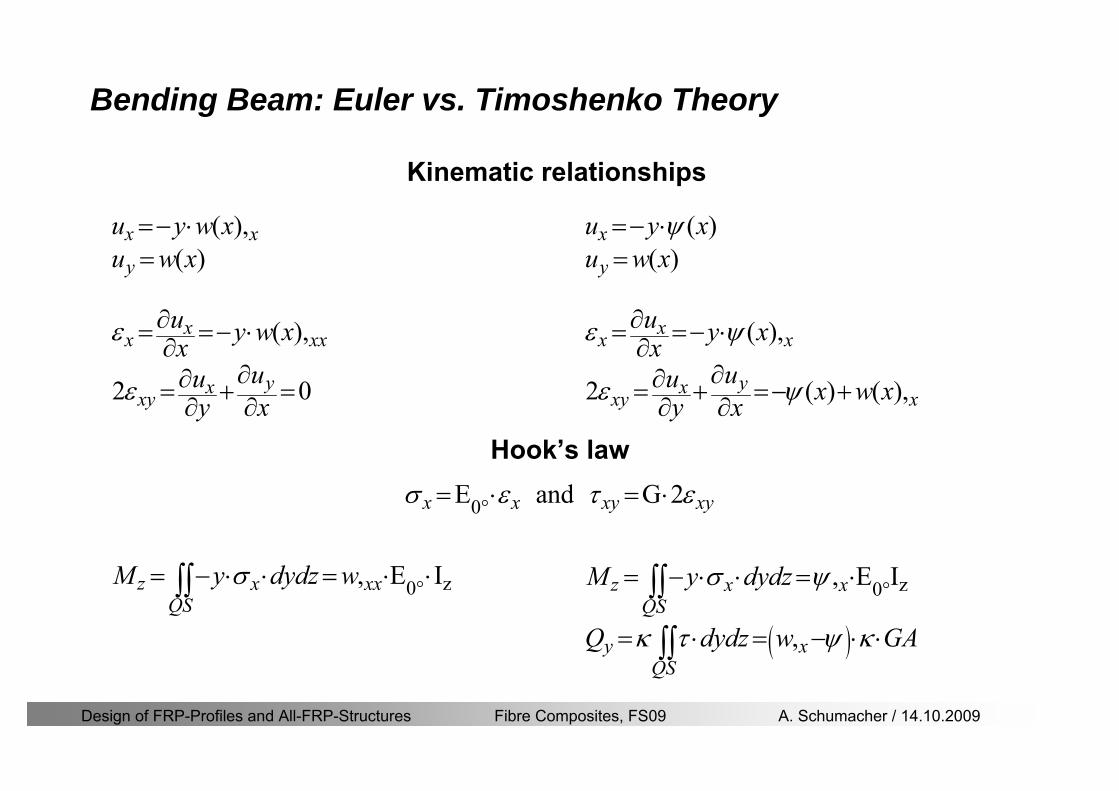
Design of FRP-Profiles and All-FRP-Structures Fibre Composites FS09 A Schumacher 14102009
Bending Beam Euler vs Timoshenko Theory
Kinematic relationships
( )( )
( )
2 0
x x
y
xx xx
yxxy
u y w xu w x
u y w xxuu
y x
ε
ε
=minus sdot=
part= =minus sdotpartpartpart= + =
part part
( )( )
( )
2 ( ) ( )
x
y
xx x
yxxy x
u y xu w x
u y xxuu x w xy x
ψ
ε ψ
ε ψ
=minus sdot=
part= =minus sdotpartpartpart= + =minus +
part part
Hookrsquos law
0degE and G 2x x xy xyσ ε τ ε= sdot = sdot
z0deg E Iz x xxQS
M y dydz wσ= minus sdot sdot = sdot sdotintint
( )
z0deg E I
z x xQS
y xQS
M y dydz
Q dydz w GA
σ ψ
κ τ ψ κ
= minus sdot sdot = sdot
= sdot = minus sdot sdot
intint
intint
Design of FRP-Profiles and All-FRP-Structures Fibre Composites FS09 A Schumacher 14102009
Bending Beam Euler vs Timoshenko Theory
Equilibrium
Solution for the simply supported beam (distributed load)
In a first approximation the deflections are calculated by direct integration of
z0deg
( ) E IxxM xw = sdot
( )( )z0deg
( ) E I 0x
x
xx x
xx x
q x w GAw GA
QM Q
ψ κψ ψ κ
minus minus sdot sdot
sdot + minus sdot sdot
=minus =
= =minus
Equilibrium on an infinitesimal beam element
Coupled second order differential equation
21 1( ) (0) 0 and ( ) 02 2
M x qLx qx w w L= minus = =
( )3 2 3
0deg z
( ) 224 E Iqxw x L Lx x= sdot minus +sdot sdot
2
0deg z
1 1 1E I 2 2xxw qLx qx⎛ ⎞= minus⎜ ⎟sdot ⎝ ⎠
(0) 0 and ( ) 0(0) 0 (0) 0 and ( ) 0 ( ) 0 x x
w w LM M L Lψ ψ
= == rarr = = rarr =
Functions4 3 2
1 2 3 4 53 2
1 2 3 4
( )
( )
w x A x A x A x A x A
x B x B x B x Bψ
= + + + +
= + + +
Design of FRP-Profiles and All-FRP-Structures Fibre Composites FS09 A Schumacher 14102009
Put in and solve for the coefficients rarr
Bending Beam Euler vs Timoshenko Theory
Use the boundary conditions and the second differential eq to calculate A1 ndash A5
( )0deg z E I 0xx xw GAψ ψ κsdot + minus sdot sdot =
1 01 1 3 3
2 02 2 4 4
24 E I4 2GA
6 E I3 GA
z
z
AB A B A
AB A B A
κ
κ
deg
deg
sdot= minus = minus minus
sdotsdot
= minus = minus minussdot
( ) ( )( )2 2
0
( )2 GA 24 E Iz
qx L x L Lx xqx L xw x
κ deg
minus + minusminus= +
sdot sdot sdot
Deflection at midspan
4
0
52 384 E Iz
qLLw⎛ ⎞⎜ ⎟⎝ ⎠
deg
sdot= sdot4 2
0
52 384 E I 8 GAz
qL q LLw κ⎛ ⎞ +⎜ ⎟⎝ ⎠
deg
sdot sdot= sdot sdot sdot
Design of FRP-Profiles and All-FRP-Structures Fibre Composites FS09 A Schumacher 14102009
General expression for the total beam deflection as a sum of the deflection due to bending and shear
GAxf
IExfxwz sdot+=
deg κ)()()( 2
0
1
Cantilever beam
Simply supported
Concentrated load (P)
Uniformly distr load (q)
Concentrated load (P)
Uniformly distr load (q)
Beam )( max1 wf
3845 4qLsdot
48
3PL
8
4qL
3
3PL
)( max1 wf
8
2qL
4PL
2
2qL
PL
)( maxwx
2L
2L
L
L
Bending Beam Euler vs Timoshenko Theory
Design of FRP-Profiles and All-FRP-Structures Fibre Composites FS09 A Schumacher 14102009
Bending Beam Euler vs Timoshenko Theory
Example influence of the shear deformation
Profile 300 x 150 mm I-beam
Load uniformly distributed
General rule of thumbfor GFRP beams withspandepth gt 25 sheardeformation can beignored
Design of FRP-Profiles and All-FRP-Structures Fibre Composites FS09 A Schumacher 14102009
Bending Beam Example
Choose an appropriate Profile for the following specifications
1 Deflections and loading
=
=
==
1300 rarr wmax=001 mwmaxL
10 kNmqdser
13 kNmqduls
30 mL
max
4 2
0
5384 E I 8 GA
d ser d serz
q L q Lw κ+
deg
sdot sdot= sdot sdot sdot
2
maxz8 2 I
d ulsq L hσ sdot= sdot
maxky
12 Ad ulsq L
τ sdot=
Design of FRP-Profiles and All-FRP-Structures Fibre Composites FS09 A Schumacher 14102009
Bending Beam Example
2 Find a profile with sufficient bending stiffness
Shear deformations are neglected in a first step
rarr from specification table choose I 240x120x12 rarr
3 Check the bending and shear stresses
6 24
0 max
1054 10 Nm5
E I 384d ser
zq Lwdeg = sdot
sdotsdotge
6 20 1369 10 NmE Izdeg = sdot
2
maxz
358 MPa8 2 Id ulsq L hσ sdot= =sdot
max
ky
1 71 MPa2 Ad ulsq L
τ sdot= =
0 185 MPab df degle =
20 MPadfτle =
Design of FRP-Profiles and All-FRP-Structures Fibre Composites FS09 A Schumacher 14102009
Bending Beam Example
m10398384
5 32
0
4
maxminus
deg
sdot=sdotsdotsdot
+sdot
sdot=
GALq
IELq
w serd
z
serd
κ
4 Check deflection (including shear deformation)
5 Remarks
The design of GFRP-profiles is mostly driven by serviceability criteria
Start the design iteration procedure using the maximal deflection criterion
max 001 mwle =
m10198384
5 32
0
4
maxminus
deg
sdot=sdot
sdot+
sdotsdot
=web
serd
z
serd
GALq
IELq
w
(77 mm) (16 mm)
Design of FRP-Profiles and All-FRP-Structures Fibre Composites FS09 A Schumacher 14102009
Bending Beam Stability problems
Lateral-torsional bucklingFlange (compressive) displace laterally to the transverse load direction
Torsional stiffness is too low (especially for open section profiles)
Theoretical calculations or design measuresrarr see eg LP Kollaacuter 2003
Mechanics of composite structuresExample
Compressive flanges are kept in place by connection to the bridge deck
Design of FRP-Profiles and All-FRP-Structures Fibre Composites FS09 A Schumacher 14102009
Bending Beam Stability problems
Flange (compressive) displaces in the direction of the transverse load
Low bending stiffness perpendicular to the pultrusion direction
Weak fiber mats
Local buckling of walls due to in-plane compression
Local buckling of walls due to in-plane shear
Web crushing and web buckling in transverse direction
Design of FRP-Profiles and All-FRP-Structures Fibre Composites FS09 A Schumacher 14102009
Axial Members
Design of FRP-Profiles and All-FRP-Structures Fibre Composites FS09 A Schumacher 14102009
Axial Members Tension
Ultimate limit state under axial tension Nd
Serviceability limit state
Remark The critical aspect of axial members in tension are neither the serviceability nor the ultimate limit state Critical is the load transfer to the GFRP profile
0NdA
tm
fγ
degle
0deg
N LE Axδ sdot= sdot
Design of FRP-Profiles and All-FRP-Structures Fibre Composites FS09 A Schumacher 14102009
Axial Members Compression
Ultimate limit state under axial compression Nd
hellip maximal compressive load
hellip Euler load
hellip Buckling length for columns
hellip coefficient for Youngrsquos modulus = 13
cc
Euler
FNd F1 N
le+
c0degC
A fF
mγsdot
=
20
Euler 2
Nm E k
E IL
πγ
degsdot sdot=
sdot
kL
m Eγ
Design of FRP-Profiles and All-FRP-Structures Fibre Composites FS09 A Schumacher 14102009
Axial Members Compression
The influence of shear deformation should be considered but in the most cases the influence will be small (less than 5)
Local buckling should be considered for short columns
For more information on the various buckling modes and effects rarr see LP Kollaacuter 2003 Mechanics of composite structures
Global buckling Local buckling
Design of FRP-Profiles and All-FRP-Structures Fibre Composites FS09 A Schumacher 14102009
Connections
Design of FRP-Profiles and All-FRP-Structures Fibre Composites FS09 A Schumacher 14102009
Connections Introduction
Design of FRP-Profiles and All-FRP-Structures Fibre Composites FS09 A Schumacher 14102009
Connections Introduction
(from Eurocomp Design Code 1996)
Design of FRP-Profiles and All-FRP-Structures Fibre Composites FS09 A Schumacher 14102009
Connections Bolted joints
Bolts = Stress concentration in the profile and the bolt
It is necessary to ensure that the bolts and the profilecan withstand this concentrated local stress compression
It is necessary to ensure that the region surroundinga group of bolts will not be torn out of the profile
Basic failure modesin bolted shearconnections
bolt shear failure
Design of FRP-Profiles and All-FRP-Structures Fibre Composites FS09 A Schumacher 14102009
Connections Bolted joints
The design procedure is comparable to the one for steel connections but since there exist no standard GFRP material rarr each manufacturer has its own design rules for bolted joints
IMPORTANT REMARKS
The direction of pultrusion and the direction of the force is RELEVANT(anisotropic material)
Use stainless or galvanised steel
Do not cut threads in the composite material
Use screws with shafts
Design of FRP-Profiles and All-FRP-Structures Fibre Composites FS09 A Schumacher 14102009
Calculation of load bearing capacity of bolts
Shear in longitudinal direction (0deg)
Shear in transverse direction (90deg)
Tensile force
Minimum distances
Connections Bolted joints (Fiberline recommendations)
Design of FRP-Profiles and All-FRP-Structures Fibre Composites FS09 A Schumacher 14102009
Joint capacity tables available for shear and tension
m
150 MPa( 13)B d
d tP γsdot sdot=
=
Shear in longitudinal direction 0deg
m
70 MPa( 13)B d
d tP γsdot sdot=
=
Shear in transverse direction 90deg
Connections Bolted joints (Fiberline recommendations)
Design of FRP-Profiles and All-FRP-Structures Fibre Composites FS09 A Schumacher 14102009
Bolted connection in shear eg shear in longitudinal direction
Connections Bolted joints (Fiberline recommendations)
γmPBolt le dt720 MPaγmPBolt le dt240 MPa
γmPBolt le dt240 MPa γmPBolt le dt240 MPaγmPBolt le dt150 MPa
Design of FRP-Profiles and All-FRP-Structures Fibre Composites FS09 A Schumacher 14102009
Bolted connections in tension
Static conditions
Bolt Tearing of bolt in threaded cross-section
Laminate Shear fracture at rim of washer
Geometry and strength
Diameter of washer2d
Tensile strength of bolt hellipfyk
Shear strength of laminatehellipfτ
Thickness of laminatet
Stress area of the boltAs
Diameter of the boltd
s ykd m
A fP γ
sdotle
2d m
d t fP τπγ
sdot sdot sdot sdotle
Connections Bolted joints (Fiberline recommendations)
Design of FRP-Profiles and All-FRP-Structures Fibre Composites FS09 A Schumacher 14102009
Connections Bonded joints
Using an adhesive agent for joining profiles can have advantages
Easy to use easy to make aesthetic joints
Typically more rigid than bolted joints
Glued joints subjected to dynamic loads are good
But be careful hellipAdhesive agents have properties that depend on time temperature humidity hellip
Failure in glued joints takes place suddenly (brittle behaviour)
The load-bearing capacity is not proportional to the area which is glued
The design of bonded joints may be based onAnalytical models for plate-to-plate connections (see Eurocomp 1996 Design Code)
Design guidelines supplemented by testing
Finite element analysis
Design of FRP-Profiles and All-FRP-Structures Fibre Composites FS09 A Schumacher 14102009
Connections Bonded joints
A bonded joint has the following three primary failure modes
adhesive failure
cohesive failure of adhesive
cohesive failure of adherend
The design of any bonded joint shall satisfy the following conditions
allowable shear stress in the adhesive is not exceeded
allowable tensile (peel) stress in the adhesive is not exceeded
allowable through-thickness tensile stress of the adhesive is not exceeded
allowable in-plane shear stress of the adherend should not be exceeded
The calculation of the stresses has to be done very carefully Often calculations are supplemented by testing
Design of FRP-Profiles and All-FRP-Structures Fibre Composites FS09 A Schumacher 14102009
Connections Bonded joints
Different types of bonded joint configurations
Research on bonded joints for structuralapplications
Design of FRP-Profiles and All-FRP-Structures Fibre Composites FS09 A Schumacher 14102009
Connections Other joints
Brackets for assembly (Fiberline)
Custom pultruded connections
Design of FRP-Profiles and All-FRP-Structures Fibre Composites FS09 A Schumacher 14102009
GFRP Some final remarks
Perpendicular to the direction of pultrusion the material is WEAK and SOFTrarr avoid such loadings if possible
In order to use pultruded GFRP-profiles economically the design must be done in a clever way eg for bridges the railings should be used as part of the load-bearing structure
GFRP structures are very light rarr vibration problems may occur
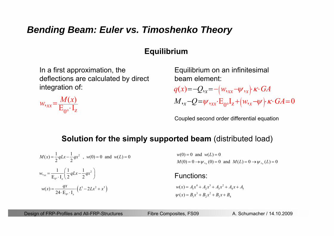
Design of FRP-Profiles and All-FRP-Structures Fibre Composites FS09 A Schumacher 14102009
Bending Beam Euler vs Timoshenko Theory
Equilibrium
Solution for the simply supported beam (distributed load)
In a first approximation the deflections are calculated by direct integration of
z0deg
( ) E IxxM xw = sdot
( )( )z0deg
( ) E I 0x
x
xx x
xx x
q x w GAw GA
QM Q
ψ κψ ψ κ
minus minus sdot sdot
sdot + minus sdot sdot
=minus =
= =minus
Equilibrium on an infinitesimal beam element
Coupled second order differential equation
21 1( ) (0) 0 and ( ) 02 2
M x qLx qx w w L= minus = =
( )3 2 3
0deg z
( ) 224 E Iqxw x L Lx x= sdot minus +sdot sdot
2
0deg z
1 1 1E I 2 2xxw qLx qx⎛ ⎞= minus⎜ ⎟sdot ⎝ ⎠
(0) 0 and ( ) 0(0) 0 (0) 0 and ( ) 0 ( ) 0 x x
w w LM M L Lψ ψ
= == rarr = = rarr =
Functions4 3 2
1 2 3 4 53 2
1 2 3 4
( )
( )
w x A x A x A x A x A
x B x B x B x Bψ
= + + + +
= + + +
Design of FRP-Profiles and All-FRP-Structures Fibre Composites FS09 A Schumacher 14102009
Put in and solve for the coefficients rarr
Bending Beam Euler vs Timoshenko Theory
Use the boundary conditions and the second differential eq to calculate A1 ndash A5
( )0deg z E I 0xx xw GAψ ψ κsdot + minus sdot sdot =
1 01 1 3 3
2 02 2 4 4
24 E I4 2GA
6 E I3 GA
z
z
AB A B A
AB A B A
κ
κ
deg
deg
sdot= minus = minus minus
sdotsdot
= minus = minus minussdot
( ) ( )( )2 2
0
( )2 GA 24 E Iz
qx L x L Lx xqx L xw x
κ deg
minus + minusminus= +
sdot sdot sdot
Deflection at midspan
4
0
52 384 E Iz
qLLw⎛ ⎞⎜ ⎟⎝ ⎠
deg
sdot= sdot4 2
0
52 384 E I 8 GAz
qL q LLw κ⎛ ⎞ +⎜ ⎟⎝ ⎠
deg
sdot sdot= sdot sdot sdot
Design of FRP-Profiles and All-FRP-Structures Fibre Composites FS09 A Schumacher 14102009
General expression for the total beam deflection as a sum of the deflection due to bending and shear
GAxf
IExfxwz sdot+=
deg κ)()()( 2
0
1
Cantilever beam
Simply supported
Concentrated load (P)
Uniformly distr load (q)
Concentrated load (P)
Uniformly distr load (q)
Beam )( max1 wf
3845 4qLsdot
48
3PL
8
4qL
3
3PL
)( max1 wf
8
2qL
4PL
2
2qL
PL
)( maxwx
2L
2L
L
L
Bending Beam Euler vs Timoshenko Theory
Design of FRP-Profiles and All-FRP-Structures Fibre Composites FS09 A Schumacher 14102009
Bending Beam Euler vs Timoshenko Theory
Example influence of the shear deformation
Profile 300 x 150 mm I-beam
Load uniformly distributed
General rule of thumbfor GFRP beams withspandepth gt 25 sheardeformation can beignored
Design of FRP-Profiles and All-FRP-Structures Fibre Composites FS09 A Schumacher 14102009
Bending Beam Example
Choose an appropriate Profile for the following specifications
1 Deflections and loading
=
=
==
1300 rarr wmax=001 mwmaxL
10 kNmqdser
13 kNmqduls
30 mL
max
4 2
0
5384 E I 8 GA
d ser d serz
q L q Lw κ+
deg
sdot sdot= sdot sdot sdot
2
maxz8 2 I
d ulsq L hσ sdot= sdot
maxky
12 Ad ulsq L
τ sdot=
Design of FRP-Profiles and All-FRP-Structures Fibre Composites FS09 A Schumacher 14102009
Bending Beam Example
2 Find a profile with sufficient bending stiffness
Shear deformations are neglected in a first step
rarr from specification table choose I 240x120x12 rarr
3 Check the bending and shear stresses
6 24
0 max
1054 10 Nm5
E I 384d ser
zq Lwdeg = sdot
sdotsdotge
6 20 1369 10 NmE Izdeg = sdot
2
maxz
358 MPa8 2 Id ulsq L hσ sdot= =sdot
max
ky
1 71 MPa2 Ad ulsq L
τ sdot= =
0 185 MPab df degle =
20 MPadfτle =
Design of FRP-Profiles and All-FRP-Structures Fibre Composites FS09 A Schumacher 14102009
Bending Beam Example
m10398384
5 32
0
4
maxminus
deg
sdot=sdotsdotsdot
+sdot
sdot=
GALq
IELq
w serd
z
serd
κ
4 Check deflection (including shear deformation)
5 Remarks
The design of GFRP-profiles is mostly driven by serviceability criteria
Start the design iteration procedure using the maximal deflection criterion
max 001 mwle =
m10198384
5 32
0
4
maxminus
deg
sdot=sdot
sdot+
sdotsdot
=web
serd
z
serd
GALq
IELq
w
(77 mm) (16 mm)
Design of FRP-Profiles and All-FRP-Structures Fibre Composites FS09 A Schumacher 14102009
Bending Beam Stability problems
Lateral-torsional bucklingFlange (compressive) displace laterally to the transverse load direction
Torsional stiffness is too low (especially for open section profiles)
Theoretical calculations or design measuresrarr see eg LP Kollaacuter 2003
Mechanics of composite structuresExample
Compressive flanges are kept in place by connection to the bridge deck
Design of FRP-Profiles and All-FRP-Structures Fibre Composites FS09 A Schumacher 14102009
Bending Beam Stability problems
Flange (compressive) displaces in the direction of the transverse load
Low bending stiffness perpendicular to the pultrusion direction
Weak fiber mats
Local buckling of walls due to in-plane compression
Local buckling of walls due to in-plane shear
Web crushing and web buckling in transverse direction
Design of FRP-Profiles and All-FRP-Structures Fibre Composites FS09 A Schumacher 14102009
Axial Members
Design of FRP-Profiles and All-FRP-Structures Fibre Composites FS09 A Schumacher 14102009
Axial Members Tension
Ultimate limit state under axial tension Nd
Serviceability limit state
Remark The critical aspect of axial members in tension are neither the serviceability nor the ultimate limit state Critical is the load transfer to the GFRP profile
0NdA
tm
fγ
degle
0deg
N LE Axδ sdot= sdot
Design of FRP-Profiles and All-FRP-Structures Fibre Composites FS09 A Schumacher 14102009
Axial Members Compression
Ultimate limit state under axial compression Nd
hellip maximal compressive load
hellip Euler load
hellip Buckling length for columns
hellip coefficient for Youngrsquos modulus = 13
cc
Euler
FNd F1 N
le+
c0degC
A fF
mγsdot
=
20
Euler 2
Nm E k
E IL
πγ
degsdot sdot=
sdot
kL
m Eγ
Design of FRP-Profiles and All-FRP-Structures Fibre Composites FS09 A Schumacher 14102009
Axial Members Compression
The influence of shear deformation should be considered but in the most cases the influence will be small (less than 5)
Local buckling should be considered for short columns
For more information on the various buckling modes and effects rarr see LP Kollaacuter 2003 Mechanics of composite structures
Global buckling Local buckling
Design of FRP-Profiles and All-FRP-Structures Fibre Composites FS09 A Schumacher 14102009
Connections
Design of FRP-Profiles and All-FRP-Structures Fibre Composites FS09 A Schumacher 14102009
Connections Introduction
Design of FRP-Profiles and All-FRP-Structures Fibre Composites FS09 A Schumacher 14102009
Connections Introduction
(from Eurocomp Design Code 1996)
Design of FRP-Profiles and All-FRP-Structures Fibre Composites FS09 A Schumacher 14102009
Connections Bolted joints
Bolts = Stress concentration in the profile and the bolt
It is necessary to ensure that the bolts and the profilecan withstand this concentrated local stress compression
It is necessary to ensure that the region surroundinga group of bolts will not be torn out of the profile
Basic failure modesin bolted shearconnections
bolt shear failure
Design of FRP-Profiles and All-FRP-Structures Fibre Composites FS09 A Schumacher 14102009
Connections Bolted joints
The design procedure is comparable to the one for steel connections but since there exist no standard GFRP material rarr each manufacturer has its own design rules for bolted joints
IMPORTANT REMARKS
The direction of pultrusion and the direction of the force is RELEVANT(anisotropic material)
Use stainless or galvanised steel
Do not cut threads in the composite material
Use screws with shafts
Design of FRP-Profiles and All-FRP-Structures Fibre Composites FS09 A Schumacher 14102009
Calculation of load bearing capacity of bolts
Shear in longitudinal direction (0deg)
Shear in transverse direction (90deg)
Tensile force
Minimum distances
Connections Bolted joints (Fiberline recommendations)
Design of FRP-Profiles and All-FRP-Structures Fibre Composites FS09 A Schumacher 14102009
Joint capacity tables available for shear and tension
m
150 MPa( 13)B d
d tP γsdot sdot=
=
Shear in longitudinal direction 0deg
m
70 MPa( 13)B d
d tP γsdot sdot=
=
Shear in transverse direction 90deg
Connections Bolted joints (Fiberline recommendations)
Design of FRP-Profiles and All-FRP-Structures Fibre Composites FS09 A Schumacher 14102009
Bolted connection in shear eg shear in longitudinal direction
Connections Bolted joints (Fiberline recommendations)
γmPBolt le dt720 MPaγmPBolt le dt240 MPa
γmPBolt le dt240 MPa γmPBolt le dt240 MPaγmPBolt le dt150 MPa
Design of FRP-Profiles and All-FRP-Structures Fibre Composites FS09 A Schumacher 14102009
Bolted connections in tension
Static conditions
Bolt Tearing of bolt in threaded cross-section
Laminate Shear fracture at rim of washer
Geometry and strength
Diameter of washer2d
Tensile strength of bolt hellipfyk
Shear strength of laminatehellipfτ
Thickness of laminatet
Stress area of the boltAs
Diameter of the boltd
s ykd m
A fP γ
sdotle
2d m
d t fP τπγ
sdot sdot sdot sdotle
Connections Bolted joints (Fiberline recommendations)
Design of FRP-Profiles and All-FRP-Structures Fibre Composites FS09 A Schumacher 14102009
Connections Bonded joints
Using an adhesive agent for joining profiles can have advantages
Easy to use easy to make aesthetic joints
Typically more rigid than bolted joints
Glued joints subjected to dynamic loads are good
But be careful hellipAdhesive agents have properties that depend on time temperature humidity hellip
Failure in glued joints takes place suddenly (brittle behaviour)
The load-bearing capacity is not proportional to the area which is glued
The design of bonded joints may be based onAnalytical models for plate-to-plate connections (see Eurocomp 1996 Design Code)
Design guidelines supplemented by testing
Finite element analysis
Design of FRP-Profiles and All-FRP-Structures Fibre Composites FS09 A Schumacher 14102009
Connections Bonded joints
A bonded joint has the following three primary failure modes
adhesive failure
cohesive failure of adhesive
cohesive failure of adherend
The design of any bonded joint shall satisfy the following conditions
allowable shear stress in the adhesive is not exceeded
allowable tensile (peel) stress in the adhesive is not exceeded
allowable through-thickness tensile stress of the adhesive is not exceeded
allowable in-plane shear stress of the adherend should not be exceeded
The calculation of the stresses has to be done very carefully Often calculations are supplemented by testing
Design of FRP-Profiles and All-FRP-Structures Fibre Composites FS09 A Schumacher 14102009
Connections Bonded joints
Different types of bonded joint configurations
Research on bonded joints for structuralapplications
Design of FRP-Profiles and All-FRP-Structures Fibre Composites FS09 A Schumacher 14102009
Connections Other joints
Brackets for assembly (Fiberline)
Custom pultruded connections
Design of FRP-Profiles and All-FRP-Structures Fibre Composites FS09 A Schumacher 14102009
GFRP Some final remarks
Perpendicular to the direction of pultrusion the material is WEAK and SOFTrarr avoid such loadings if possible
In order to use pultruded GFRP-profiles economically the design must be done in a clever way eg for bridges the railings should be used as part of the load-bearing structure
GFRP structures are very light rarr vibration problems may occur
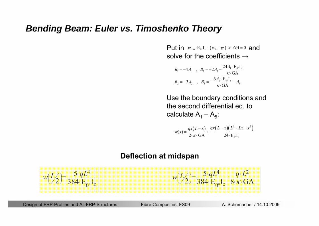
Design of FRP-Profiles and All-FRP-Structures Fibre Composites FS09 A Schumacher 14102009
Put in and solve for the coefficients rarr
Bending Beam Euler vs Timoshenko Theory
Use the boundary conditions and the second differential eq to calculate A1 ndash A5
( )0deg z E I 0xx xw GAψ ψ κsdot + minus sdot sdot =
1 01 1 3 3
2 02 2 4 4
24 E I4 2GA
6 E I3 GA
z
z
AB A B A
AB A B A
κ
κ
deg
deg
sdot= minus = minus minus
sdotsdot
= minus = minus minussdot
( ) ( )( )2 2
0
( )2 GA 24 E Iz
qx L x L Lx xqx L xw x
κ deg
minus + minusminus= +
sdot sdot sdot
Deflection at midspan
4
0
52 384 E Iz
qLLw⎛ ⎞⎜ ⎟⎝ ⎠
deg
sdot= sdot4 2
0
52 384 E I 8 GAz
qL q LLw κ⎛ ⎞ +⎜ ⎟⎝ ⎠
deg
sdot sdot= sdot sdot sdot
Design of FRP-Profiles and All-FRP-Structures Fibre Composites FS09 A Schumacher 14102009
General expression for the total beam deflection as a sum of the deflection due to bending and shear
GAxf
IExfxwz sdot+=
deg κ)()()( 2
0
1
Cantilever beam
Simply supported
Concentrated load (P)
Uniformly distr load (q)
Concentrated load (P)
Uniformly distr load (q)
Beam )( max1 wf
3845 4qLsdot
48
3PL
8
4qL
3
3PL
)( max1 wf
8
2qL
4PL
2
2qL
PL
)( maxwx
2L
2L
L
L
Bending Beam Euler vs Timoshenko Theory
Design of FRP-Profiles and All-FRP-Structures Fibre Composites FS09 A Schumacher 14102009
Bending Beam Euler vs Timoshenko Theory
Example influence of the shear deformation
Profile 300 x 150 mm I-beam
Load uniformly distributed
General rule of thumbfor GFRP beams withspandepth gt 25 sheardeformation can beignored
Design of FRP-Profiles and All-FRP-Structures Fibre Composites FS09 A Schumacher 14102009
Bending Beam Example
Choose an appropriate Profile for the following specifications
1 Deflections and loading
=
=
==
1300 rarr wmax=001 mwmaxL
10 kNmqdser
13 kNmqduls
30 mL
max
4 2
0
5384 E I 8 GA
d ser d serz
q L q Lw κ+
deg
sdot sdot= sdot sdot sdot
2
maxz8 2 I
d ulsq L hσ sdot= sdot
maxky
12 Ad ulsq L
τ sdot=
Design of FRP-Profiles and All-FRP-Structures Fibre Composites FS09 A Schumacher 14102009
Bending Beam Example
2 Find a profile with sufficient bending stiffness
Shear deformations are neglected in a first step
rarr from specification table choose I 240x120x12 rarr
3 Check the bending and shear stresses
6 24
0 max
1054 10 Nm5
E I 384d ser
zq Lwdeg = sdot
sdotsdotge
6 20 1369 10 NmE Izdeg = sdot
2
maxz
358 MPa8 2 Id ulsq L hσ sdot= =sdot
max
ky
1 71 MPa2 Ad ulsq L
τ sdot= =
0 185 MPab df degle =
20 MPadfτle =
Design of FRP-Profiles and All-FRP-Structures Fibre Composites FS09 A Schumacher 14102009
Bending Beam Example
m10398384
5 32
0
4
maxminus
deg
sdot=sdotsdotsdot
+sdot
sdot=
GALq
IELq
w serd
z
serd
κ
4 Check deflection (including shear deformation)
5 Remarks
The design of GFRP-profiles is mostly driven by serviceability criteria
Start the design iteration procedure using the maximal deflection criterion
max 001 mwle =
m10198384
5 32
0
4
maxminus
deg
sdot=sdot
sdot+
sdotsdot
=web
serd
z
serd
GALq
IELq
w
(77 mm) (16 mm)
Design of FRP-Profiles and All-FRP-Structures Fibre Composites FS09 A Schumacher 14102009
Bending Beam Stability problems
Lateral-torsional bucklingFlange (compressive) displace laterally to the transverse load direction
Torsional stiffness is too low (especially for open section profiles)
Theoretical calculations or design measuresrarr see eg LP Kollaacuter 2003
Mechanics of composite structuresExample
Compressive flanges are kept in place by connection to the bridge deck
Design of FRP-Profiles and All-FRP-Structures Fibre Composites FS09 A Schumacher 14102009
Bending Beam Stability problems
Flange (compressive) displaces in the direction of the transverse load
Low bending stiffness perpendicular to the pultrusion direction
Weak fiber mats
Local buckling of walls due to in-plane compression
Local buckling of walls due to in-plane shear
Web crushing and web buckling in transverse direction
Design of FRP-Profiles and All-FRP-Structures Fibre Composites FS09 A Schumacher 14102009
Axial Members
Design of FRP-Profiles and All-FRP-Structures Fibre Composites FS09 A Schumacher 14102009
Axial Members Tension
Ultimate limit state under axial tension Nd
Serviceability limit state
Remark The critical aspect of axial members in tension are neither the serviceability nor the ultimate limit state Critical is the load transfer to the GFRP profile
0NdA
tm
fγ
degle
0deg
N LE Axδ sdot= sdot
Design of FRP-Profiles and All-FRP-Structures Fibre Composites FS09 A Schumacher 14102009
Axial Members Compression
Ultimate limit state under axial compression Nd
hellip maximal compressive load
hellip Euler load
hellip Buckling length for columns
hellip coefficient for Youngrsquos modulus = 13
cc
Euler
FNd F1 N
le+
c0degC
A fF
mγsdot
=
20
Euler 2
Nm E k
E IL
πγ
degsdot sdot=
sdot
kL
m Eγ
Design of FRP-Profiles and All-FRP-Structures Fibre Composites FS09 A Schumacher 14102009
Axial Members Compression
The influence of shear deformation should be considered but in the most cases the influence will be small (less than 5)
Local buckling should be considered for short columns
For more information on the various buckling modes and effects rarr see LP Kollaacuter 2003 Mechanics of composite structures
Global buckling Local buckling
Design of FRP-Profiles and All-FRP-Structures Fibre Composites FS09 A Schumacher 14102009
Connections
Design of FRP-Profiles and All-FRP-Structures Fibre Composites FS09 A Schumacher 14102009
Connections Introduction
Design of FRP-Profiles and All-FRP-Structures Fibre Composites FS09 A Schumacher 14102009
Connections Introduction
(from Eurocomp Design Code 1996)
Design of FRP-Profiles and All-FRP-Structures Fibre Composites FS09 A Schumacher 14102009
Connections Bolted joints
Bolts = Stress concentration in the profile and the bolt
It is necessary to ensure that the bolts and the profilecan withstand this concentrated local stress compression
It is necessary to ensure that the region surroundinga group of bolts will not be torn out of the profile
Basic failure modesin bolted shearconnections
bolt shear failure
Design of FRP-Profiles and All-FRP-Structures Fibre Composites FS09 A Schumacher 14102009
Connections Bolted joints
The design procedure is comparable to the one for steel connections but since there exist no standard GFRP material rarr each manufacturer has its own design rules for bolted joints
IMPORTANT REMARKS
The direction of pultrusion and the direction of the force is RELEVANT(anisotropic material)
Use stainless or galvanised steel
Do not cut threads in the composite material
Use screws with shafts
Design of FRP-Profiles and All-FRP-Structures Fibre Composites FS09 A Schumacher 14102009
Calculation of load bearing capacity of bolts
Shear in longitudinal direction (0deg)
Shear in transverse direction (90deg)
Tensile force
Minimum distances
Connections Bolted joints (Fiberline recommendations)
Design of FRP-Profiles and All-FRP-Structures Fibre Composites FS09 A Schumacher 14102009
Joint capacity tables available for shear and tension
m
150 MPa( 13)B d
d tP γsdot sdot=
=
Shear in longitudinal direction 0deg
m
70 MPa( 13)B d
d tP γsdot sdot=
=
Shear in transverse direction 90deg
Connections Bolted joints (Fiberline recommendations)
Design of FRP-Profiles and All-FRP-Structures Fibre Composites FS09 A Schumacher 14102009
Bolted connection in shear eg shear in longitudinal direction
Connections Bolted joints (Fiberline recommendations)
γmPBolt le dt720 MPaγmPBolt le dt240 MPa
γmPBolt le dt240 MPa γmPBolt le dt240 MPaγmPBolt le dt150 MPa
Design of FRP-Profiles and All-FRP-Structures Fibre Composites FS09 A Schumacher 14102009
Bolted connections in tension
Static conditions
Bolt Tearing of bolt in threaded cross-section
Laminate Shear fracture at rim of washer
Geometry and strength
Diameter of washer2d
Tensile strength of bolt hellipfyk
Shear strength of laminatehellipfτ
Thickness of laminatet
Stress area of the boltAs
Diameter of the boltd
s ykd m
A fP γ
sdotle
2d m
d t fP τπγ
sdot sdot sdot sdotle
Connections Bolted joints (Fiberline recommendations)
Design of FRP-Profiles and All-FRP-Structures Fibre Composites FS09 A Schumacher 14102009
Connections Bonded joints
Using an adhesive agent for joining profiles can have advantages
Easy to use easy to make aesthetic joints
Typically more rigid than bolted joints
Glued joints subjected to dynamic loads are good
But be careful hellipAdhesive agents have properties that depend on time temperature humidity hellip
Failure in glued joints takes place suddenly (brittle behaviour)
The load-bearing capacity is not proportional to the area which is glued
The design of bonded joints may be based onAnalytical models for plate-to-plate connections (see Eurocomp 1996 Design Code)
Design guidelines supplemented by testing
Finite element analysis
Design of FRP-Profiles and All-FRP-Structures Fibre Composites FS09 A Schumacher 14102009
Connections Bonded joints
A bonded joint has the following three primary failure modes
adhesive failure
cohesive failure of adhesive
cohesive failure of adherend
The design of any bonded joint shall satisfy the following conditions
allowable shear stress in the adhesive is not exceeded
allowable tensile (peel) stress in the adhesive is not exceeded
allowable through-thickness tensile stress of the adhesive is not exceeded
allowable in-plane shear stress of the adherend should not be exceeded
The calculation of the stresses has to be done very carefully Often calculations are supplemented by testing
Design of FRP-Profiles and All-FRP-Structures Fibre Composites FS09 A Schumacher 14102009
Connections Bonded joints
Different types of bonded joint configurations
Research on bonded joints for structuralapplications
Design of FRP-Profiles and All-FRP-Structures Fibre Composites FS09 A Schumacher 14102009
Connections Other joints
Brackets for assembly (Fiberline)
Custom pultruded connections
Design of FRP-Profiles and All-FRP-Structures Fibre Composites FS09 A Schumacher 14102009
GFRP Some final remarks
Perpendicular to the direction of pultrusion the material is WEAK and SOFTrarr avoid such loadings if possible
In order to use pultruded GFRP-profiles economically the design must be done in a clever way eg for bridges the railings should be used as part of the load-bearing structure
GFRP structures are very light rarr vibration problems may occur
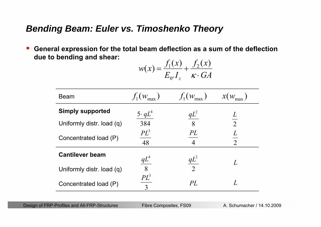
Design of FRP-Profiles and All-FRP-Structures Fibre Composites FS09 A Schumacher 14102009
General expression for the total beam deflection as a sum of the deflection due to bending and shear
GAxf
IExfxwz sdot+=
deg κ)()()( 2
0
1
Cantilever beam
Simply supported
Concentrated load (P)
Uniformly distr load (q)
Concentrated load (P)
Uniformly distr load (q)
Beam )( max1 wf
3845 4qLsdot
48
3PL
8
4qL
3
3PL
)( max1 wf
8
2qL
4PL
2
2qL
PL
)( maxwx
2L
2L
L
L
Bending Beam Euler vs Timoshenko Theory
Design of FRP-Profiles and All-FRP-Structures Fibre Composites FS09 A Schumacher 14102009
Bending Beam Euler vs Timoshenko Theory
Example influence of the shear deformation
Profile 300 x 150 mm I-beam
Load uniformly distributed
General rule of thumbfor GFRP beams withspandepth gt 25 sheardeformation can beignored
Design of FRP-Profiles and All-FRP-Structures Fibre Composites FS09 A Schumacher 14102009
Bending Beam Example
Choose an appropriate Profile for the following specifications
1 Deflections and loading
=
=
==
1300 rarr wmax=001 mwmaxL
10 kNmqdser
13 kNmqduls
30 mL
max
4 2
0
5384 E I 8 GA
d ser d serz
q L q Lw κ+
deg
sdot sdot= sdot sdot sdot
2
maxz8 2 I
d ulsq L hσ sdot= sdot
maxky
12 Ad ulsq L
τ sdot=
Design of FRP-Profiles and All-FRP-Structures Fibre Composites FS09 A Schumacher 14102009
Bending Beam Example
2 Find a profile with sufficient bending stiffness
Shear deformations are neglected in a first step
rarr from specification table choose I 240x120x12 rarr
3 Check the bending and shear stresses
6 24
0 max
1054 10 Nm5
E I 384d ser
zq Lwdeg = sdot
sdotsdotge
6 20 1369 10 NmE Izdeg = sdot
2
maxz
358 MPa8 2 Id ulsq L hσ sdot= =sdot
max
ky
1 71 MPa2 Ad ulsq L
τ sdot= =
0 185 MPab df degle =
20 MPadfτle =
Design of FRP-Profiles and All-FRP-Structures Fibre Composites FS09 A Schumacher 14102009
Bending Beam Example
m10398384
5 32
0
4
maxminus
deg
sdot=sdotsdotsdot
+sdot
sdot=
GALq
IELq
w serd
z
serd
κ
4 Check deflection (including shear deformation)
5 Remarks
The design of GFRP-profiles is mostly driven by serviceability criteria
Start the design iteration procedure using the maximal deflection criterion
max 001 mwle =
m10198384
5 32
0
4
maxminus
deg
sdot=sdot
sdot+
sdotsdot
=web
serd
z
serd
GALq
IELq
w
(77 mm) (16 mm)
Design of FRP-Profiles and All-FRP-Structures Fibre Composites FS09 A Schumacher 14102009
Bending Beam Stability problems
Lateral-torsional bucklingFlange (compressive) displace laterally to the transverse load direction
Torsional stiffness is too low (especially for open section profiles)
Theoretical calculations or design measuresrarr see eg LP Kollaacuter 2003
Mechanics of composite structuresExample
Compressive flanges are kept in place by connection to the bridge deck
Design of FRP-Profiles and All-FRP-Structures Fibre Composites FS09 A Schumacher 14102009
Bending Beam Stability problems
Flange (compressive) displaces in the direction of the transverse load
Low bending stiffness perpendicular to the pultrusion direction
Weak fiber mats
Local buckling of walls due to in-plane compression
Local buckling of walls due to in-plane shear
Web crushing and web buckling in transverse direction
Design of FRP-Profiles and All-FRP-Structures Fibre Composites FS09 A Schumacher 14102009
Axial Members
Design of FRP-Profiles and All-FRP-Structures Fibre Composites FS09 A Schumacher 14102009
Axial Members Tension
Ultimate limit state under axial tension Nd
Serviceability limit state
Remark The critical aspect of axial members in tension are neither the serviceability nor the ultimate limit state Critical is the load transfer to the GFRP profile
0NdA
tm
fγ
degle
0deg
N LE Axδ sdot= sdot
Design of FRP-Profiles and All-FRP-Structures Fibre Composites FS09 A Schumacher 14102009
Axial Members Compression
Ultimate limit state under axial compression Nd
hellip maximal compressive load
hellip Euler load
hellip Buckling length for columns
hellip coefficient for Youngrsquos modulus = 13
cc
Euler
FNd F1 N
le+
c0degC
A fF
mγsdot
=
20
Euler 2
Nm E k
E IL
πγ
degsdot sdot=
sdot
kL
m Eγ
Design of FRP-Profiles and All-FRP-Structures Fibre Composites FS09 A Schumacher 14102009
Axial Members Compression
The influence of shear deformation should be considered but in the most cases the influence will be small (less than 5)
Local buckling should be considered for short columns
For more information on the various buckling modes and effects rarr see LP Kollaacuter 2003 Mechanics of composite structures
Global buckling Local buckling
Design of FRP-Profiles and All-FRP-Structures Fibre Composites FS09 A Schumacher 14102009
Connections
Design of FRP-Profiles and All-FRP-Structures Fibre Composites FS09 A Schumacher 14102009
Connections Introduction
Design of FRP-Profiles and All-FRP-Structures Fibre Composites FS09 A Schumacher 14102009
Connections Introduction
(from Eurocomp Design Code 1996)
Design of FRP-Profiles and All-FRP-Structures Fibre Composites FS09 A Schumacher 14102009
Connections Bolted joints
Bolts = Stress concentration in the profile and the bolt
It is necessary to ensure that the bolts and the profilecan withstand this concentrated local stress compression
It is necessary to ensure that the region surroundinga group of bolts will not be torn out of the profile
Basic failure modesin bolted shearconnections
bolt shear failure
Design of FRP-Profiles and All-FRP-Structures Fibre Composites FS09 A Schumacher 14102009
Connections Bolted joints
The design procedure is comparable to the one for steel connections but since there exist no standard GFRP material rarr each manufacturer has its own design rules for bolted joints
IMPORTANT REMARKS
The direction of pultrusion and the direction of the force is RELEVANT(anisotropic material)
Use stainless or galvanised steel
Do not cut threads in the composite material
Use screws with shafts
Design of FRP-Profiles and All-FRP-Structures Fibre Composites FS09 A Schumacher 14102009
Calculation of load bearing capacity of bolts
Shear in longitudinal direction (0deg)
Shear in transverse direction (90deg)
Tensile force
Minimum distances
Connections Bolted joints (Fiberline recommendations)
Design of FRP-Profiles and All-FRP-Structures Fibre Composites FS09 A Schumacher 14102009
Joint capacity tables available for shear and tension
m
150 MPa( 13)B d
d tP γsdot sdot=
=
Shear in longitudinal direction 0deg
m
70 MPa( 13)B d
d tP γsdot sdot=
=
Shear in transverse direction 90deg
Connections Bolted joints (Fiberline recommendations)
Design of FRP-Profiles and All-FRP-Structures Fibre Composites FS09 A Schumacher 14102009
Bolted connection in shear eg shear in longitudinal direction
Connections Bolted joints (Fiberline recommendations)
γmPBolt le dt720 MPaγmPBolt le dt240 MPa
γmPBolt le dt240 MPa γmPBolt le dt240 MPaγmPBolt le dt150 MPa
Design of FRP-Profiles and All-FRP-Structures Fibre Composites FS09 A Schumacher 14102009
Bolted connections in tension
Static conditions
Bolt Tearing of bolt in threaded cross-section
Laminate Shear fracture at rim of washer
Geometry and strength
Diameter of washer2d
Tensile strength of bolt hellipfyk
Shear strength of laminatehellipfτ
Thickness of laminatet
Stress area of the boltAs
Diameter of the boltd
s ykd m
A fP γ
sdotle
2d m
d t fP τπγ
sdot sdot sdot sdotle
Connections Bolted joints (Fiberline recommendations)
Design of FRP-Profiles and All-FRP-Structures Fibre Composites FS09 A Schumacher 14102009
Connections Bonded joints
Using an adhesive agent for joining profiles can have advantages
Easy to use easy to make aesthetic joints
Typically more rigid than bolted joints
Glued joints subjected to dynamic loads are good
But be careful hellipAdhesive agents have properties that depend on time temperature humidity hellip
Failure in glued joints takes place suddenly (brittle behaviour)
The load-bearing capacity is not proportional to the area which is glued
The design of bonded joints may be based onAnalytical models for plate-to-plate connections (see Eurocomp 1996 Design Code)
Design guidelines supplemented by testing
Finite element analysis
Design of FRP-Profiles and All-FRP-Structures Fibre Composites FS09 A Schumacher 14102009
Connections Bonded joints
A bonded joint has the following three primary failure modes
adhesive failure
cohesive failure of adhesive
cohesive failure of adherend
The design of any bonded joint shall satisfy the following conditions
allowable shear stress in the adhesive is not exceeded
allowable tensile (peel) stress in the adhesive is not exceeded
allowable through-thickness tensile stress of the adhesive is not exceeded
allowable in-plane shear stress of the adherend should not be exceeded
The calculation of the stresses has to be done very carefully Often calculations are supplemented by testing
Design of FRP-Profiles and All-FRP-Structures Fibre Composites FS09 A Schumacher 14102009
Connections Bonded joints
Different types of bonded joint configurations
Research on bonded joints for structuralapplications
Design of FRP-Profiles and All-FRP-Structures Fibre Composites FS09 A Schumacher 14102009
Connections Other joints
Brackets for assembly (Fiberline)
Custom pultruded connections
Design of FRP-Profiles and All-FRP-Structures Fibre Composites FS09 A Schumacher 14102009
GFRP Some final remarks
Perpendicular to the direction of pultrusion the material is WEAK and SOFTrarr avoid such loadings if possible
In order to use pultruded GFRP-profiles economically the design must be done in a clever way eg for bridges the railings should be used as part of the load-bearing structure
GFRP structures are very light rarr vibration problems may occur
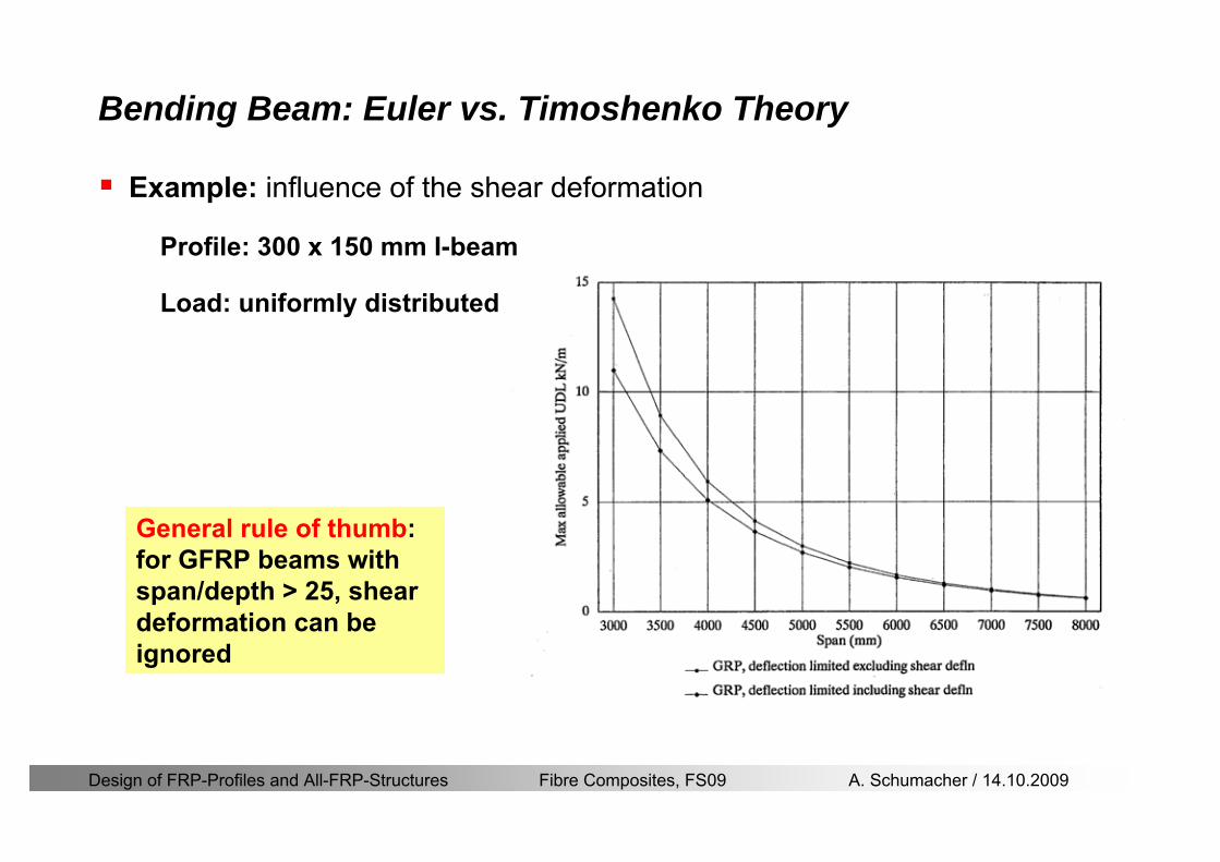
Design of FRP-Profiles and All-FRP-Structures Fibre Composites FS09 A Schumacher 14102009
Bending Beam Euler vs Timoshenko Theory
Example influence of the shear deformation
Profile 300 x 150 mm I-beam
Load uniformly distributed
General rule of thumbfor GFRP beams withspandepth gt 25 sheardeformation can beignored
Design of FRP-Profiles and All-FRP-Structures Fibre Composites FS09 A Schumacher 14102009
Bending Beam Example
Choose an appropriate Profile for the following specifications
1 Deflections and loading
=
=
==
1300 rarr wmax=001 mwmaxL
10 kNmqdser
13 kNmqduls
30 mL
max
4 2
0
5384 E I 8 GA
d ser d serz
q L q Lw κ+
deg
sdot sdot= sdot sdot sdot
2
maxz8 2 I
d ulsq L hσ sdot= sdot
maxky
12 Ad ulsq L
τ sdot=
Design of FRP-Profiles and All-FRP-Structures Fibre Composites FS09 A Schumacher 14102009
Bending Beam Example
2 Find a profile with sufficient bending stiffness
Shear deformations are neglected in a first step
rarr from specification table choose I 240x120x12 rarr
3 Check the bending and shear stresses
6 24
0 max
1054 10 Nm5
E I 384d ser
zq Lwdeg = sdot
sdotsdotge
6 20 1369 10 NmE Izdeg = sdot
2
maxz
358 MPa8 2 Id ulsq L hσ sdot= =sdot
max
ky
1 71 MPa2 Ad ulsq L
τ sdot= =
0 185 MPab df degle =
20 MPadfτle =
Design of FRP-Profiles and All-FRP-Structures Fibre Composites FS09 A Schumacher 14102009
Bending Beam Example
m10398384
5 32
0
4
maxminus
deg
sdot=sdotsdotsdot
+sdot
sdot=
GALq
IELq
w serd
z
serd
κ
4 Check deflection (including shear deformation)
5 Remarks
The design of GFRP-profiles is mostly driven by serviceability criteria
Start the design iteration procedure using the maximal deflection criterion
max 001 mwle =
m10198384
5 32
0
4
maxminus
deg
sdot=sdot
sdot+
sdotsdot
=web
serd
z
serd
GALq
IELq
w
(77 mm) (16 mm)
Design of FRP-Profiles and All-FRP-Structures Fibre Composites FS09 A Schumacher 14102009
Bending Beam Stability problems
Lateral-torsional bucklingFlange (compressive) displace laterally to the transverse load direction
Torsional stiffness is too low (especially for open section profiles)
Theoretical calculations or design measuresrarr see eg LP Kollaacuter 2003
Mechanics of composite structuresExample
Compressive flanges are kept in place by connection to the bridge deck
Design of FRP-Profiles and All-FRP-Structures Fibre Composites FS09 A Schumacher 14102009
Bending Beam Stability problems
Flange (compressive) displaces in the direction of the transverse load
Low bending stiffness perpendicular to the pultrusion direction
Weak fiber mats
Local buckling of walls due to in-plane compression
Local buckling of walls due to in-plane shear
Web crushing and web buckling in transverse direction
Design of FRP-Profiles and All-FRP-Structures Fibre Composites FS09 A Schumacher 14102009
Axial Members
Design of FRP-Profiles and All-FRP-Structures Fibre Composites FS09 A Schumacher 14102009
Axial Members Tension
Ultimate limit state under axial tension Nd
Serviceability limit state
Remark The critical aspect of axial members in tension are neither the serviceability nor the ultimate limit state Critical is the load transfer to the GFRP profile
0NdA
tm
fγ
degle
0deg
N LE Axδ sdot= sdot
Design of FRP-Profiles and All-FRP-Structures Fibre Composites FS09 A Schumacher 14102009
Axial Members Compression
Ultimate limit state under axial compression Nd
hellip maximal compressive load
hellip Euler load
hellip Buckling length for columns
hellip coefficient for Youngrsquos modulus = 13
cc
Euler
FNd F1 N
le+
c0degC
A fF
mγsdot
=
20
Euler 2
Nm E k
E IL
πγ
degsdot sdot=
sdot
kL
m Eγ
Design of FRP-Profiles and All-FRP-Structures Fibre Composites FS09 A Schumacher 14102009
Axial Members Compression
The influence of shear deformation should be considered but in the most cases the influence will be small (less than 5)
Local buckling should be considered for short columns
For more information on the various buckling modes and effects rarr see LP Kollaacuter 2003 Mechanics of composite structures
Global buckling Local buckling
Design of FRP-Profiles and All-FRP-Structures Fibre Composites FS09 A Schumacher 14102009
Connections
Design of FRP-Profiles and All-FRP-Structures Fibre Composites FS09 A Schumacher 14102009
Connections Introduction
Design of FRP-Profiles and All-FRP-Structures Fibre Composites FS09 A Schumacher 14102009
Connections Introduction
(from Eurocomp Design Code 1996)
Design of FRP-Profiles and All-FRP-Structures Fibre Composites FS09 A Schumacher 14102009
Connections Bolted joints
Bolts = Stress concentration in the profile and the bolt
It is necessary to ensure that the bolts and the profilecan withstand this concentrated local stress compression
It is necessary to ensure that the region surroundinga group of bolts will not be torn out of the profile
Basic failure modesin bolted shearconnections
bolt shear failure
Design of FRP-Profiles and All-FRP-Structures Fibre Composites FS09 A Schumacher 14102009
Connections Bolted joints
The design procedure is comparable to the one for steel connections but since there exist no standard GFRP material rarr each manufacturer has its own design rules for bolted joints
IMPORTANT REMARKS
The direction of pultrusion and the direction of the force is RELEVANT(anisotropic material)
Use stainless or galvanised steel
Do not cut threads in the composite material
Use screws with shafts
Design of FRP-Profiles and All-FRP-Structures Fibre Composites FS09 A Schumacher 14102009
Calculation of load bearing capacity of bolts
Shear in longitudinal direction (0deg)
Shear in transverse direction (90deg)
Tensile force
Minimum distances
Connections Bolted joints (Fiberline recommendations)
Design of FRP-Profiles and All-FRP-Structures Fibre Composites FS09 A Schumacher 14102009
Joint capacity tables available for shear and tension
m
150 MPa( 13)B d
d tP γsdot sdot=
=
Shear in longitudinal direction 0deg
m
70 MPa( 13)B d
d tP γsdot sdot=
=
Shear in transverse direction 90deg
Connections Bolted joints (Fiberline recommendations)
Design of FRP-Profiles and All-FRP-Structures Fibre Composites FS09 A Schumacher 14102009
Bolted connection in shear eg shear in longitudinal direction
Connections Bolted joints (Fiberline recommendations)
γmPBolt le dt720 MPaγmPBolt le dt240 MPa
γmPBolt le dt240 MPa γmPBolt le dt240 MPaγmPBolt le dt150 MPa
Design of FRP-Profiles and All-FRP-Structures Fibre Composites FS09 A Schumacher 14102009
Bolted connections in tension
Static conditions
Bolt Tearing of bolt in threaded cross-section
Laminate Shear fracture at rim of washer
Geometry and strength
Diameter of washer2d
Tensile strength of bolt hellipfyk
Shear strength of laminatehellipfτ
Thickness of laminatet
Stress area of the boltAs
Diameter of the boltd
s ykd m
A fP γ
sdotle
2d m
d t fP τπγ
sdot sdot sdot sdotle
Connections Bolted joints (Fiberline recommendations)
Design of FRP-Profiles and All-FRP-Structures Fibre Composites FS09 A Schumacher 14102009
Connections Bonded joints
Using an adhesive agent for joining profiles can have advantages
Easy to use easy to make aesthetic joints
Typically more rigid than bolted joints
Glued joints subjected to dynamic loads are good
But be careful hellipAdhesive agents have properties that depend on time temperature humidity hellip
Failure in glued joints takes place suddenly (brittle behaviour)
The load-bearing capacity is not proportional to the area which is glued
The design of bonded joints may be based onAnalytical models for plate-to-plate connections (see Eurocomp 1996 Design Code)
Design guidelines supplemented by testing
Finite element analysis
Design of FRP-Profiles and All-FRP-Structures Fibre Composites FS09 A Schumacher 14102009
Connections Bonded joints
A bonded joint has the following three primary failure modes
adhesive failure
cohesive failure of adhesive
cohesive failure of adherend
The design of any bonded joint shall satisfy the following conditions
allowable shear stress in the adhesive is not exceeded
allowable tensile (peel) stress in the adhesive is not exceeded
allowable through-thickness tensile stress of the adhesive is not exceeded
allowable in-plane shear stress of the adherend should not be exceeded
The calculation of the stresses has to be done very carefully Often calculations are supplemented by testing
Design of FRP-Profiles and All-FRP-Structures Fibre Composites FS09 A Schumacher 14102009
Connections Bonded joints
Different types of bonded joint configurations
Research on bonded joints for structuralapplications
Design of FRP-Profiles and All-FRP-Structures Fibre Composites FS09 A Schumacher 14102009
Connections Other joints
Brackets for assembly (Fiberline)
Custom pultruded connections
Design of FRP-Profiles and All-FRP-Structures Fibre Composites FS09 A Schumacher 14102009
GFRP Some final remarks
Perpendicular to the direction of pultrusion the material is WEAK and SOFTrarr avoid such loadings if possible
In order to use pultruded GFRP-profiles economically the design must be done in a clever way eg for bridges the railings should be used as part of the load-bearing structure
GFRP structures are very light rarr vibration problems may occur
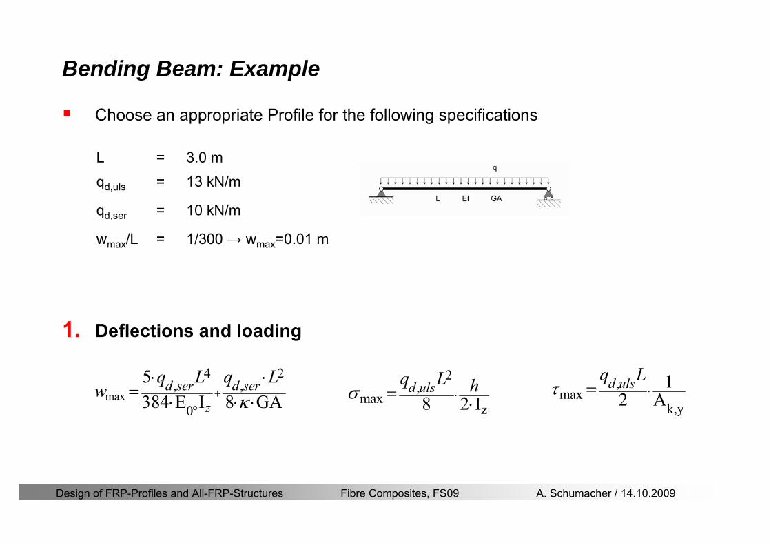
Design of FRP-Profiles and All-FRP-Structures Fibre Composites FS09 A Schumacher 14102009
Bending Beam Example
Choose an appropriate Profile for the following specifications
1 Deflections and loading
=
=
==
1300 rarr wmax=001 mwmaxL
10 kNmqdser
13 kNmqduls
30 mL
max
4 2
0
5384 E I 8 GA
d ser d serz
q L q Lw κ+
deg
sdot sdot= sdot sdot sdot
2
maxz8 2 I
d ulsq L hσ sdot= sdot
maxky
12 Ad ulsq L
τ sdot=
Design of FRP-Profiles and All-FRP-Structures Fibre Composites FS09 A Schumacher 14102009
Bending Beam Example
2 Find a profile with sufficient bending stiffness
Shear deformations are neglected in a first step
rarr from specification table choose I 240x120x12 rarr
3 Check the bending and shear stresses
6 24
0 max
1054 10 Nm5
E I 384d ser
zq Lwdeg = sdot
sdotsdotge
6 20 1369 10 NmE Izdeg = sdot
2
maxz
358 MPa8 2 Id ulsq L hσ sdot= =sdot
max
ky
1 71 MPa2 Ad ulsq L
τ sdot= =
0 185 MPab df degle =
20 MPadfτle =
Design of FRP-Profiles and All-FRP-Structures Fibre Composites FS09 A Schumacher 14102009
Bending Beam Example
m10398384
5 32
0
4
maxminus
deg
sdot=sdotsdotsdot
+sdot
sdot=
GALq
IELq
w serd
z
serd
κ
4 Check deflection (including shear deformation)
5 Remarks
The design of GFRP-profiles is mostly driven by serviceability criteria
Start the design iteration procedure using the maximal deflection criterion
max 001 mwle =
m10198384
5 32
0
4
maxminus
deg
sdot=sdot
sdot+
sdotsdot
=web
serd
z
serd
GALq
IELq
w
(77 mm) (16 mm)
Design of FRP-Profiles and All-FRP-Structures Fibre Composites FS09 A Schumacher 14102009
Bending Beam Stability problems
Lateral-torsional bucklingFlange (compressive) displace laterally to the transverse load direction
Torsional stiffness is too low (especially for open section profiles)
Theoretical calculations or design measuresrarr see eg LP Kollaacuter 2003
Mechanics of composite structuresExample
Compressive flanges are kept in place by connection to the bridge deck
Design of FRP-Profiles and All-FRP-Structures Fibre Composites FS09 A Schumacher 14102009
Bending Beam Stability problems
Flange (compressive) displaces in the direction of the transverse load
Low bending stiffness perpendicular to the pultrusion direction
Weak fiber mats
Local buckling of walls due to in-plane compression
Local buckling of walls due to in-plane shear
Web crushing and web buckling in transverse direction
Design of FRP-Profiles and All-FRP-Structures Fibre Composites FS09 A Schumacher 14102009
Axial Members
Design of FRP-Profiles and All-FRP-Structures Fibre Composites FS09 A Schumacher 14102009
Axial Members Tension
Ultimate limit state under axial tension Nd
Serviceability limit state
Remark The critical aspect of axial members in tension are neither the serviceability nor the ultimate limit state Critical is the load transfer to the GFRP profile
0NdA
tm
fγ
degle
0deg
N LE Axδ sdot= sdot
Design of FRP-Profiles and All-FRP-Structures Fibre Composites FS09 A Schumacher 14102009
Axial Members Compression
Ultimate limit state under axial compression Nd
hellip maximal compressive load
hellip Euler load
hellip Buckling length for columns
hellip coefficient for Youngrsquos modulus = 13
cc
Euler
FNd F1 N
le+
c0degC
A fF
mγsdot
=
20
Euler 2
Nm E k
E IL
πγ
degsdot sdot=
sdot
kL
m Eγ
Design of FRP-Profiles and All-FRP-Structures Fibre Composites FS09 A Schumacher 14102009
Axial Members Compression
The influence of shear deformation should be considered but in the most cases the influence will be small (less than 5)
Local buckling should be considered for short columns
For more information on the various buckling modes and effects rarr see LP Kollaacuter 2003 Mechanics of composite structures
Global buckling Local buckling
Design of FRP-Profiles and All-FRP-Structures Fibre Composites FS09 A Schumacher 14102009
Connections
Design of FRP-Profiles and All-FRP-Structures Fibre Composites FS09 A Schumacher 14102009
Connections Introduction
Design of FRP-Profiles and All-FRP-Structures Fibre Composites FS09 A Schumacher 14102009
Connections Introduction
(from Eurocomp Design Code 1996)
Design of FRP-Profiles and All-FRP-Structures Fibre Composites FS09 A Schumacher 14102009
Connections Bolted joints
Bolts = Stress concentration in the profile and the bolt
It is necessary to ensure that the bolts and the profilecan withstand this concentrated local stress compression
It is necessary to ensure that the region surroundinga group of bolts will not be torn out of the profile
Basic failure modesin bolted shearconnections
bolt shear failure
Design of FRP-Profiles and All-FRP-Structures Fibre Composites FS09 A Schumacher 14102009
Connections Bolted joints
The design procedure is comparable to the one for steel connections but since there exist no standard GFRP material rarr each manufacturer has its own design rules for bolted joints
IMPORTANT REMARKS
The direction of pultrusion and the direction of the force is RELEVANT(anisotropic material)
Use stainless or galvanised steel
Do not cut threads in the composite material
Use screws with shafts
Design of FRP-Profiles and All-FRP-Structures Fibre Composites FS09 A Schumacher 14102009
Calculation of load bearing capacity of bolts
Shear in longitudinal direction (0deg)
Shear in transverse direction (90deg)
Tensile force
Minimum distances
Connections Bolted joints (Fiberline recommendations)
Design of FRP-Profiles and All-FRP-Structures Fibre Composites FS09 A Schumacher 14102009
Joint capacity tables available for shear and tension
m
150 MPa( 13)B d
d tP γsdot sdot=
=
Shear in longitudinal direction 0deg
m
70 MPa( 13)B d
d tP γsdot sdot=
=
Shear in transverse direction 90deg
Connections Bolted joints (Fiberline recommendations)
Design of FRP-Profiles and All-FRP-Structures Fibre Composites FS09 A Schumacher 14102009
Bolted connection in shear eg shear in longitudinal direction
Connections Bolted joints (Fiberline recommendations)
γmPBolt le dt720 MPaγmPBolt le dt240 MPa
γmPBolt le dt240 MPa γmPBolt le dt240 MPaγmPBolt le dt150 MPa
Design of FRP-Profiles and All-FRP-Structures Fibre Composites FS09 A Schumacher 14102009
Bolted connections in tension
Static conditions
Bolt Tearing of bolt in threaded cross-section
Laminate Shear fracture at rim of washer
Geometry and strength
Diameter of washer2d
Tensile strength of bolt hellipfyk
Shear strength of laminatehellipfτ
Thickness of laminatet
Stress area of the boltAs
Diameter of the boltd
s ykd m
A fP γ
sdotle
2d m
d t fP τπγ
sdot sdot sdot sdotle
Connections Bolted joints (Fiberline recommendations)
Design of FRP-Profiles and All-FRP-Structures Fibre Composites FS09 A Schumacher 14102009
Connections Bonded joints
Using an adhesive agent for joining profiles can have advantages
Easy to use easy to make aesthetic joints
Typically more rigid than bolted joints
Glued joints subjected to dynamic loads are good
But be careful hellipAdhesive agents have properties that depend on time temperature humidity hellip
Failure in glued joints takes place suddenly (brittle behaviour)
The load-bearing capacity is not proportional to the area which is glued
The design of bonded joints may be based onAnalytical models for plate-to-plate connections (see Eurocomp 1996 Design Code)
Design guidelines supplemented by testing
Finite element analysis
Design of FRP-Profiles and All-FRP-Structures Fibre Composites FS09 A Schumacher 14102009
Connections Bonded joints
A bonded joint has the following three primary failure modes
adhesive failure
cohesive failure of adhesive
cohesive failure of adherend
The design of any bonded joint shall satisfy the following conditions
allowable shear stress in the adhesive is not exceeded
allowable tensile (peel) stress in the adhesive is not exceeded
allowable through-thickness tensile stress of the adhesive is not exceeded
allowable in-plane shear stress of the adherend should not be exceeded
The calculation of the stresses has to be done very carefully Often calculations are supplemented by testing
Design of FRP-Profiles and All-FRP-Structures Fibre Composites FS09 A Schumacher 14102009
Connections Bonded joints
Different types of bonded joint configurations
Research on bonded joints for structuralapplications
Design of FRP-Profiles and All-FRP-Structures Fibre Composites FS09 A Schumacher 14102009
Connections Other joints
Brackets for assembly (Fiberline)
Custom pultruded connections
Design of FRP-Profiles and All-FRP-Structures Fibre Composites FS09 A Schumacher 14102009
GFRP Some final remarks
Perpendicular to the direction of pultrusion the material is WEAK and SOFTrarr avoid such loadings if possible
In order to use pultruded GFRP-profiles economically the design must be done in a clever way eg for bridges the railings should be used as part of the load-bearing structure
GFRP structures are very light rarr vibration problems may occur
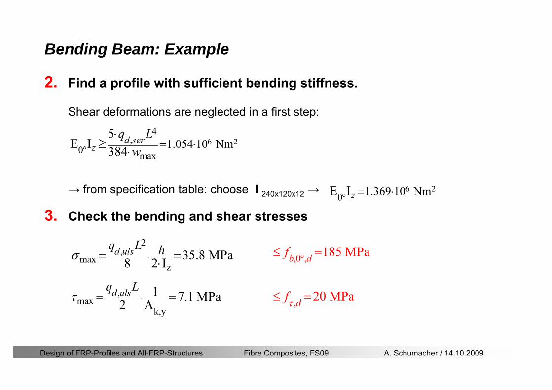
Design of FRP-Profiles and All-FRP-Structures Fibre Composites FS09 A Schumacher 14102009
Bending Beam Example
2 Find a profile with sufficient bending stiffness
Shear deformations are neglected in a first step
rarr from specification table choose I 240x120x12 rarr
3 Check the bending and shear stresses
6 24
0 max
1054 10 Nm5
E I 384d ser
zq Lwdeg = sdot
sdotsdotge
6 20 1369 10 NmE Izdeg = sdot
2
maxz
358 MPa8 2 Id ulsq L hσ sdot= =sdot
max
ky
1 71 MPa2 Ad ulsq L
τ sdot= =
0 185 MPab df degle =
20 MPadfτle =
Design of FRP-Profiles and All-FRP-Structures Fibre Composites FS09 A Schumacher 14102009
Bending Beam Example
m10398384
5 32
0
4
maxminus
deg
sdot=sdotsdotsdot
+sdot
sdot=
GALq
IELq
w serd
z
serd
κ
4 Check deflection (including shear deformation)
5 Remarks
The design of GFRP-profiles is mostly driven by serviceability criteria
Start the design iteration procedure using the maximal deflection criterion
max 001 mwle =
m10198384
5 32
0
4
maxminus
deg
sdot=sdot
sdot+
sdotsdot
=web
serd
z
serd
GALq
IELq
w
(77 mm) (16 mm)
Design of FRP-Profiles and All-FRP-Structures Fibre Composites FS09 A Schumacher 14102009
Bending Beam Stability problems
Lateral-torsional bucklingFlange (compressive) displace laterally to the transverse load direction
Torsional stiffness is too low (especially for open section profiles)
Theoretical calculations or design measuresrarr see eg LP Kollaacuter 2003
Mechanics of composite structuresExample
Compressive flanges are kept in place by connection to the bridge deck
Design of FRP-Profiles and All-FRP-Structures Fibre Composites FS09 A Schumacher 14102009
Bending Beam Stability problems
Flange (compressive) displaces in the direction of the transverse load
Low bending stiffness perpendicular to the pultrusion direction
Weak fiber mats
Local buckling of walls due to in-plane compression
Local buckling of walls due to in-plane shear
Web crushing and web buckling in transverse direction
Design of FRP-Profiles and All-FRP-Structures Fibre Composites FS09 A Schumacher 14102009
Axial Members
Design of FRP-Profiles and All-FRP-Structures Fibre Composites FS09 A Schumacher 14102009
Axial Members Tension
Ultimate limit state under axial tension Nd
Serviceability limit state
Remark The critical aspect of axial members in tension are neither the serviceability nor the ultimate limit state Critical is the load transfer to the GFRP profile
0NdA
tm
fγ
degle
0deg
N LE Axδ sdot= sdot
Design of FRP-Profiles and All-FRP-Structures Fibre Composites FS09 A Schumacher 14102009
Axial Members Compression
Ultimate limit state under axial compression Nd
hellip maximal compressive load
hellip Euler load
hellip Buckling length for columns
hellip coefficient for Youngrsquos modulus = 13
cc
Euler
FNd F1 N
le+
c0degC
A fF
mγsdot
=
20
Euler 2
Nm E k
E IL
πγ
degsdot sdot=
sdot
kL
m Eγ
Design of FRP-Profiles and All-FRP-Structures Fibre Composites FS09 A Schumacher 14102009
Axial Members Compression
The influence of shear deformation should be considered but in the most cases the influence will be small (less than 5)
Local buckling should be considered for short columns
For more information on the various buckling modes and effects rarr see LP Kollaacuter 2003 Mechanics of composite structures
Global buckling Local buckling
Design of FRP-Profiles and All-FRP-Structures Fibre Composites FS09 A Schumacher 14102009
Connections
Design of FRP-Profiles and All-FRP-Structures Fibre Composites FS09 A Schumacher 14102009
Connections Introduction
Design of FRP-Profiles and All-FRP-Structures Fibre Composites FS09 A Schumacher 14102009
Connections Introduction
(from Eurocomp Design Code 1996)
Design of FRP-Profiles and All-FRP-Structures Fibre Composites FS09 A Schumacher 14102009
Connections Bolted joints
Bolts = Stress concentration in the profile and the bolt
It is necessary to ensure that the bolts and the profilecan withstand this concentrated local stress compression
It is necessary to ensure that the region surroundinga group of bolts will not be torn out of the profile
Basic failure modesin bolted shearconnections
bolt shear failure
Design of FRP-Profiles and All-FRP-Structures Fibre Composites FS09 A Schumacher 14102009
Connections Bolted joints
The design procedure is comparable to the one for steel connections but since there exist no standard GFRP material rarr each manufacturer has its own design rules for bolted joints
IMPORTANT REMARKS
The direction of pultrusion and the direction of the force is RELEVANT(anisotropic material)
Use stainless or galvanised steel
Do not cut threads in the composite material
Use screws with shafts
Design of FRP-Profiles and All-FRP-Structures Fibre Composites FS09 A Schumacher 14102009
Calculation of load bearing capacity of bolts
Shear in longitudinal direction (0deg)
Shear in transverse direction (90deg)
Tensile force
Minimum distances
Connections Bolted joints (Fiberline recommendations)
Design of FRP-Profiles and All-FRP-Structures Fibre Composites FS09 A Schumacher 14102009
Joint capacity tables available for shear and tension
m
150 MPa( 13)B d
d tP γsdot sdot=
=
Shear in longitudinal direction 0deg
m
70 MPa( 13)B d
d tP γsdot sdot=
=
Shear in transverse direction 90deg
Connections Bolted joints (Fiberline recommendations)
Design of FRP-Profiles and All-FRP-Structures Fibre Composites FS09 A Schumacher 14102009
Bolted connection in shear eg shear in longitudinal direction
Connections Bolted joints (Fiberline recommendations)
γmPBolt le dt720 MPaγmPBolt le dt240 MPa
γmPBolt le dt240 MPa γmPBolt le dt240 MPaγmPBolt le dt150 MPa
Design of FRP-Profiles and All-FRP-Structures Fibre Composites FS09 A Schumacher 14102009
Bolted connections in tension
Static conditions
Bolt Tearing of bolt in threaded cross-section
Laminate Shear fracture at rim of washer
Geometry and strength
Diameter of washer2d
Tensile strength of bolt hellipfyk
Shear strength of laminatehellipfτ
Thickness of laminatet
Stress area of the boltAs
Diameter of the boltd
s ykd m
A fP γ
sdotle
2d m
d t fP τπγ
sdot sdot sdot sdotle
Connections Bolted joints (Fiberline recommendations)
Design of FRP-Profiles and All-FRP-Structures Fibre Composites FS09 A Schumacher 14102009
Connections Bonded joints
Using an adhesive agent for joining profiles can have advantages
Easy to use easy to make aesthetic joints
Typically more rigid than bolted joints
Glued joints subjected to dynamic loads are good
But be careful hellipAdhesive agents have properties that depend on time temperature humidity hellip
Failure in glued joints takes place suddenly (brittle behaviour)
The load-bearing capacity is not proportional to the area which is glued
The design of bonded joints may be based onAnalytical models for plate-to-plate connections (see Eurocomp 1996 Design Code)
Design guidelines supplemented by testing
Finite element analysis
Design of FRP-Profiles and All-FRP-Structures Fibre Composites FS09 A Schumacher 14102009
Connections Bonded joints
A bonded joint has the following three primary failure modes
adhesive failure
cohesive failure of adhesive
cohesive failure of adherend
The design of any bonded joint shall satisfy the following conditions
allowable shear stress in the adhesive is not exceeded
allowable tensile (peel) stress in the adhesive is not exceeded
allowable through-thickness tensile stress of the adhesive is not exceeded
allowable in-plane shear stress of the adherend should not be exceeded
The calculation of the stresses has to be done very carefully Often calculations are supplemented by testing
Design of FRP-Profiles and All-FRP-Structures Fibre Composites FS09 A Schumacher 14102009
Connections Bonded joints
Different types of bonded joint configurations
Research on bonded joints for structuralapplications
Design of FRP-Profiles and All-FRP-Structures Fibre Composites FS09 A Schumacher 14102009
Connections Other joints
Brackets for assembly (Fiberline)
Custom pultruded connections
Design of FRP-Profiles and All-FRP-Structures Fibre Composites FS09 A Schumacher 14102009
GFRP Some final remarks
Perpendicular to the direction of pultrusion the material is WEAK and SOFTrarr avoid such loadings if possible
In order to use pultruded GFRP-profiles economically the design must be done in a clever way eg for bridges the railings should be used as part of the load-bearing structure
GFRP structures are very light rarr vibration problems may occur
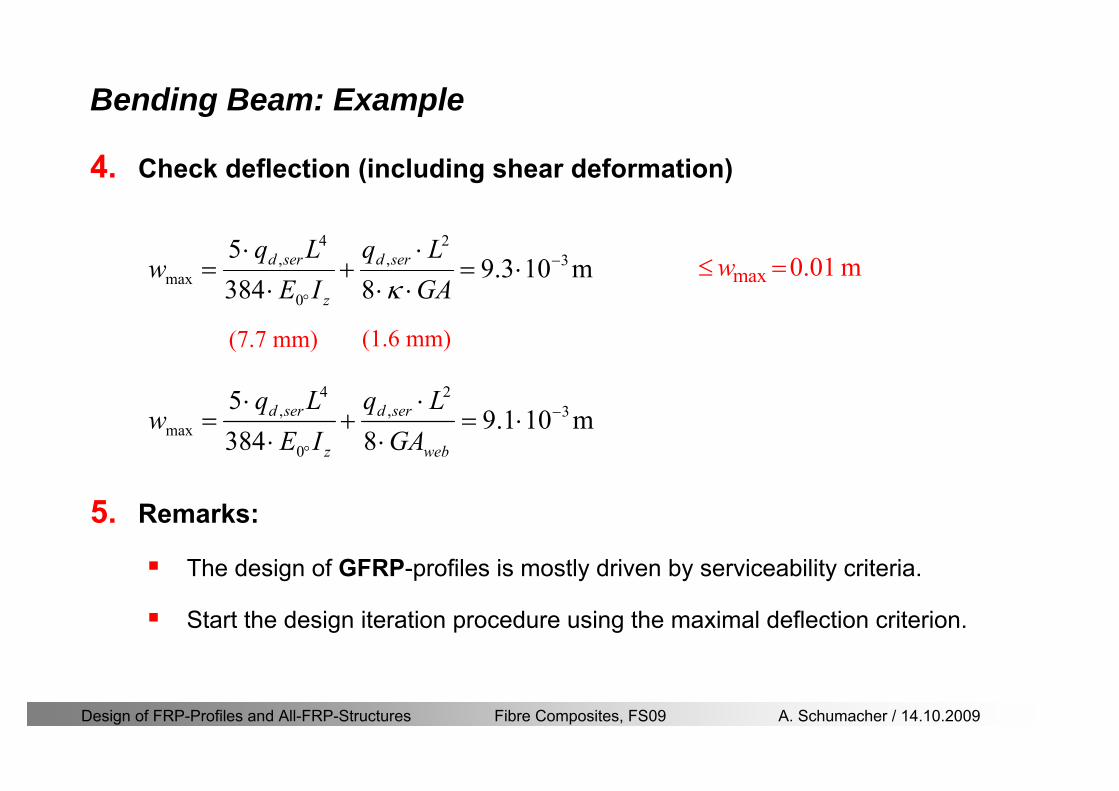
Design of FRP-Profiles and All-FRP-Structures Fibre Composites FS09 A Schumacher 14102009
Bending Beam Example
m10398384
5 32
0
4
maxminus
deg
sdot=sdotsdotsdot
+sdot
sdot=
GALq
IELq
w serd
z
serd
κ
4 Check deflection (including shear deformation)
5 Remarks
The design of GFRP-profiles is mostly driven by serviceability criteria
Start the design iteration procedure using the maximal deflection criterion
max 001 mwle =
m10198384
5 32
0
4
maxminus
deg
sdot=sdot
sdot+
sdotsdot
=web
serd
z
serd
GALq
IELq
w
(77 mm) (16 mm)
Design of FRP-Profiles and All-FRP-Structures Fibre Composites FS09 A Schumacher 14102009
Bending Beam Stability problems
Lateral-torsional bucklingFlange (compressive) displace laterally to the transverse load direction
Torsional stiffness is too low (especially for open section profiles)
Theoretical calculations or design measuresrarr see eg LP Kollaacuter 2003
Mechanics of composite structuresExample
Compressive flanges are kept in place by connection to the bridge deck
Design of FRP-Profiles and All-FRP-Structures Fibre Composites FS09 A Schumacher 14102009
Bending Beam Stability problems
Flange (compressive) displaces in the direction of the transverse load
Low bending stiffness perpendicular to the pultrusion direction
Weak fiber mats
Local buckling of walls due to in-plane compression
Local buckling of walls due to in-plane shear
Web crushing and web buckling in transverse direction
Design of FRP-Profiles and All-FRP-Structures Fibre Composites FS09 A Schumacher 14102009
Axial Members
Design of FRP-Profiles and All-FRP-Structures Fibre Composites FS09 A Schumacher 14102009
Axial Members Tension
Ultimate limit state under axial tension Nd
Serviceability limit state
Remark The critical aspect of axial members in tension are neither the serviceability nor the ultimate limit state Critical is the load transfer to the GFRP profile
0NdA
tm
fγ
degle
0deg
N LE Axδ sdot= sdot
Design of FRP-Profiles and All-FRP-Structures Fibre Composites FS09 A Schumacher 14102009
Axial Members Compression
Ultimate limit state under axial compression Nd
hellip maximal compressive load
hellip Euler load
hellip Buckling length for columns
hellip coefficient for Youngrsquos modulus = 13
cc
Euler
FNd F1 N
le+
c0degC
A fF
mγsdot
=
20
Euler 2
Nm E k
E IL
πγ
degsdot sdot=
sdot
kL
m Eγ
Design of FRP-Profiles and All-FRP-Structures Fibre Composites FS09 A Schumacher 14102009
Axial Members Compression
The influence of shear deformation should be considered but in the most cases the influence will be small (less than 5)
Local buckling should be considered for short columns
For more information on the various buckling modes and effects rarr see LP Kollaacuter 2003 Mechanics of composite structures
Global buckling Local buckling
Design of FRP-Profiles and All-FRP-Structures Fibre Composites FS09 A Schumacher 14102009
Connections
Design of FRP-Profiles and All-FRP-Structures Fibre Composites FS09 A Schumacher 14102009
Connections Introduction
Design of FRP-Profiles and All-FRP-Structures Fibre Composites FS09 A Schumacher 14102009
Connections Introduction
(from Eurocomp Design Code 1996)
Design of FRP-Profiles and All-FRP-Structures Fibre Composites FS09 A Schumacher 14102009
Connections Bolted joints
Bolts = Stress concentration in the profile and the bolt
It is necessary to ensure that the bolts and the profilecan withstand this concentrated local stress compression
It is necessary to ensure that the region surroundinga group of bolts will not be torn out of the profile
Basic failure modesin bolted shearconnections
bolt shear failure
Design of FRP-Profiles and All-FRP-Structures Fibre Composites FS09 A Schumacher 14102009
Connections Bolted joints
The design procedure is comparable to the one for steel connections but since there exist no standard GFRP material rarr each manufacturer has its own design rules for bolted joints
IMPORTANT REMARKS
The direction of pultrusion and the direction of the force is RELEVANT(anisotropic material)
Use stainless or galvanised steel
Do not cut threads in the composite material
Use screws with shafts
Design of FRP-Profiles and All-FRP-Structures Fibre Composites FS09 A Schumacher 14102009
Calculation of load bearing capacity of bolts
Shear in longitudinal direction (0deg)
Shear in transverse direction (90deg)
Tensile force
Minimum distances
Connections Bolted joints (Fiberline recommendations)
Design of FRP-Profiles and All-FRP-Structures Fibre Composites FS09 A Schumacher 14102009
Joint capacity tables available for shear and tension
m
150 MPa( 13)B d
d tP γsdot sdot=
=
Shear in longitudinal direction 0deg
m
70 MPa( 13)B d
d tP γsdot sdot=
=
Shear in transverse direction 90deg
Connections Bolted joints (Fiberline recommendations)
Design of FRP-Profiles and All-FRP-Structures Fibre Composites FS09 A Schumacher 14102009
Bolted connection in shear eg shear in longitudinal direction
Connections Bolted joints (Fiberline recommendations)
γmPBolt le dt720 MPaγmPBolt le dt240 MPa
γmPBolt le dt240 MPa γmPBolt le dt240 MPaγmPBolt le dt150 MPa
Design of FRP-Profiles and All-FRP-Structures Fibre Composites FS09 A Schumacher 14102009
Bolted connections in tension
Static conditions
Bolt Tearing of bolt in threaded cross-section
Laminate Shear fracture at rim of washer
Geometry and strength
Diameter of washer2d
Tensile strength of bolt hellipfyk
Shear strength of laminatehellipfτ
Thickness of laminatet
Stress area of the boltAs
Diameter of the boltd
s ykd m
A fP γ
sdotle
2d m
d t fP τπγ
sdot sdot sdot sdotle
Connections Bolted joints (Fiberline recommendations)
Design of FRP-Profiles and All-FRP-Structures Fibre Composites FS09 A Schumacher 14102009
Connections Bonded joints
Using an adhesive agent for joining profiles can have advantages
Easy to use easy to make aesthetic joints
Typically more rigid than bolted joints
Glued joints subjected to dynamic loads are good
But be careful hellipAdhesive agents have properties that depend on time temperature humidity hellip
Failure in glued joints takes place suddenly (brittle behaviour)
The load-bearing capacity is not proportional to the area which is glued
The design of bonded joints may be based onAnalytical models for plate-to-plate connections (see Eurocomp 1996 Design Code)
Design guidelines supplemented by testing
Finite element analysis
Design of FRP-Profiles and All-FRP-Structures Fibre Composites FS09 A Schumacher 14102009
Connections Bonded joints
A bonded joint has the following three primary failure modes
adhesive failure
cohesive failure of adhesive
cohesive failure of adherend
The design of any bonded joint shall satisfy the following conditions
allowable shear stress in the adhesive is not exceeded
allowable tensile (peel) stress in the adhesive is not exceeded
allowable through-thickness tensile stress of the adhesive is not exceeded
allowable in-plane shear stress of the adherend should not be exceeded
The calculation of the stresses has to be done very carefully Often calculations are supplemented by testing
Design of FRP-Profiles and All-FRP-Structures Fibre Composites FS09 A Schumacher 14102009
Connections Bonded joints
Different types of bonded joint configurations
Research on bonded joints for structuralapplications
Design of FRP-Profiles and All-FRP-Structures Fibre Composites FS09 A Schumacher 14102009
Connections Other joints
Brackets for assembly (Fiberline)
Custom pultruded connections
Design of FRP-Profiles and All-FRP-Structures Fibre Composites FS09 A Schumacher 14102009
GFRP Some final remarks
Perpendicular to the direction of pultrusion the material is WEAK and SOFTrarr avoid such loadings if possible
In order to use pultruded GFRP-profiles economically the design must be done in a clever way eg for bridges the railings should be used as part of the load-bearing structure
GFRP structures are very light rarr vibration problems may occur
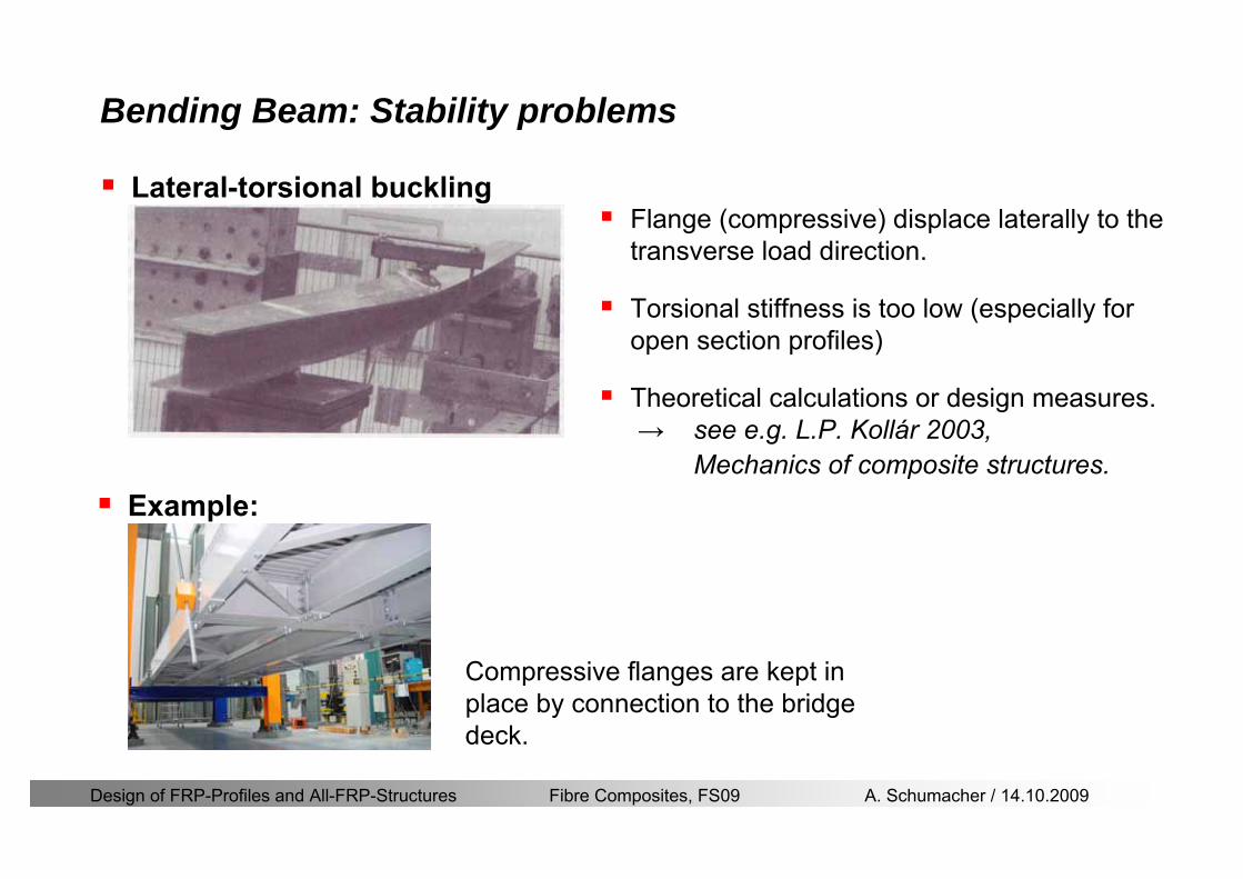
Design of FRP-Profiles and All-FRP-Structures Fibre Composites FS09 A Schumacher 14102009
Bending Beam Stability problems
Lateral-torsional bucklingFlange (compressive) displace laterally to the transverse load direction
Torsional stiffness is too low (especially for open section profiles)
Theoretical calculations or design measuresrarr see eg LP Kollaacuter 2003
Mechanics of composite structuresExample
Compressive flanges are kept in place by connection to the bridge deck
Design of FRP-Profiles and All-FRP-Structures Fibre Composites FS09 A Schumacher 14102009
Bending Beam Stability problems
Flange (compressive) displaces in the direction of the transverse load
Low bending stiffness perpendicular to the pultrusion direction
Weak fiber mats
Local buckling of walls due to in-plane compression
Local buckling of walls due to in-plane shear
Web crushing and web buckling in transverse direction
Design of FRP-Profiles and All-FRP-Structures Fibre Composites FS09 A Schumacher 14102009
Axial Members
Design of FRP-Profiles and All-FRP-Structures Fibre Composites FS09 A Schumacher 14102009
Axial Members Tension
Ultimate limit state under axial tension Nd
Serviceability limit state
Remark The critical aspect of axial members in tension are neither the serviceability nor the ultimate limit state Critical is the load transfer to the GFRP profile
0NdA
tm
fγ
degle
0deg
N LE Axδ sdot= sdot
Design of FRP-Profiles and All-FRP-Structures Fibre Composites FS09 A Schumacher 14102009
Axial Members Compression
Ultimate limit state under axial compression Nd
hellip maximal compressive load
hellip Euler load
hellip Buckling length for columns
hellip coefficient for Youngrsquos modulus = 13
cc
Euler
FNd F1 N
le+
c0degC
A fF
mγsdot
=
20
Euler 2
Nm E k
E IL
πγ
degsdot sdot=
sdot
kL
m Eγ
Design of FRP-Profiles and All-FRP-Structures Fibre Composites FS09 A Schumacher 14102009
Axial Members Compression
The influence of shear deformation should be considered but in the most cases the influence will be small (less than 5)
Local buckling should be considered for short columns
For more information on the various buckling modes and effects rarr see LP Kollaacuter 2003 Mechanics of composite structures
Global buckling Local buckling
Design of FRP-Profiles and All-FRP-Structures Fibre Composites FS09 A Schumacher 14102009
Connections
Design of FRP-Profiles and All-FRP-Structures Fibre Composites FS09 A Schumacher 14102009
Connections Introduction
Design of FRP-Profiles and All-FRP-Structures Fibre Composites FS09 A Schumacher 14102009
Connections Introduction
(from Eurocomp Design Code 1996)
Design of FRP-Profiles and All-FRP-Structures Fibre Composites FS09 A Schumacher 14102009
Connections Bolted joints
Bolts = Stress concentration in the profile and the bolt
It is necessary to ensure that the bolts and the profilecan withstand this concentrated local stress compression
It is necessary to ensure that the region surroundinga group of bolts will not be torn out of the profile
Basic failure modesin bolted shearconnections
bolt shear failure
Design of FRP-Profiles and All-FRP-Structures Fibre Composites FS09 A Schumacher 14102009
Connections Bolted joints
The design procedure is comparable to the one for steel connections but since there exist no standard GFRP material rarr each manufacturer has its own design rules for bolted joints
IMPORTANT REMARKS
The direction of pultrusion and the direction of the force is RELEVANT(anisotropic material)
Use stainless or galvanised steel
Do not cut threads in the composite material
Use screws with shafts
Design of FRP-Profiles and All-FRP-Structures Fibre Composites FS09 A Schumacher 14102009
Calculation of load bearing capacity of bolts
Shear in longitudinal direction (0deg)
Shear in transverse direction (90deg)
Tensile force
Minimum distances
Connections Bolted joints (Fiberline recommendations)
Design of FRP-Profiles and All-FRP-Structures Fibre Composites FS09 A Schumacher 14102009
Joint capacity tables available for shear and tension
m
150 MPa( 13)B d
d tP γsdot sdot=
=
Shear in longitudinal direction 0deg
m
70 MPa( 13)B d
d tP γsdot sdot=
=
Shear in transverse direction 90deg
Connections Bolted joints (Fiberline recommendations)
Design of FRP-Profiles and All-FRP-Structures Fibre Composites FS09 A Schumacher 14102009
Bolted connection in shear eg shear in longitudinal direction
Connections Bolted joints (Fiberline recommendations)
γmPBolt le dt720 MPaγmPBolt le dt240 MPa
γmPBolt le dt240 MPa γmPBolt le dt240 MPaγmPBolt le dt150 MPa
Design of FRP-Profiles and All-FRP-Structures Fibre Composites FS09 A Schumacher 14102009
Bolted connections in tension
Static conditions
Bolt Tearing of bolt in threaded cross-section
Laminate Shear fracture at rim of washer
Geometry and strength
Diameter of washer2d
Tensile strength of bolt hellipfyk
Shear strength of laminatehellipfτ
Thickness of laminatet
Stress area of the boltAs
Diameter of the boltd
s ykd m
A fP γ
sdotle
2d m
d t fP τπγ
sdot sdot sdot sdotle
Connections Bolted joints (Fiberline recommendations)
Design of FRP-Profiles and All-FRP-Structures Fibre Composites FS09 A Schumacher 14102009
Connections Bonded joints
Using an adhesive agent for joining profiles can have advantages
Easy to use easy to make aesthetic joints
Typically more rigid than bolted joints
Glued joints subjected to dynamic loads are good
But be careful hellipAdhesive agents have properties that depend on time temperature humidity hellip
Failure in glued joints takes place suddenly (brittle behaviour)
The load-bearing capacity is not proportional to the area which is glued
The design of bonded joints may be based onAnalytical models for plate-to-plate connections (see Eurocomp 1996 Design Code)
Design guidelines supplemented by testing
Finite element analysis
Design of FRP-Profiles and All-FRP-Structures Fibre Composites FS09 A Schumacher 14102009
Connections Bonded joints
A bonded joint has the following three primary failure modes
adhesive failure
cohesive failure of adhesive
cohesive failure of adherend
The design of any bonded joint shall satisfy the following conditions
allowable shear stress in the adhesive is not exceeded
allowable tensile (peel) stress in the adhesive is not exceeded
allowable through-thickness tensile stress of the adhesive is not exceeded
allowable in-plane shear stress of the adherend should not be exceeded
The calculation of the stresses has to be done very carefully Often calculations are supplemented by testing
Design of FRP-Profiles and All-FRP-Structures Fibre Composites FS09 A Schumacher 14102009
Connections Bonded joints
Different types of bonded joint configurations
Research on bonded joints for structuralapplications
Design of FRP-Profiles and All-FRP-Structures Fibre Composites FS09 A Schumacher 14102009
Connections Other joints
Brackets for assembly (Fiberline)
Custom pultruded connections
Design of FRP-Profiles and All-FRP-Structures Fibre Composites FS09 A Schumacher 14102009
GFRP Some final remarks
Perpendicular to the direction of pultrusion the material is WEAK and SOFTrarr avoid such loadings if possible
In order to use pultruded GFRP-profiles economically the design must be done in a clever way eg for bridges the railings should be used as part of the load-bearing structure
GFRP structures are very light rarr vibration problems may occur
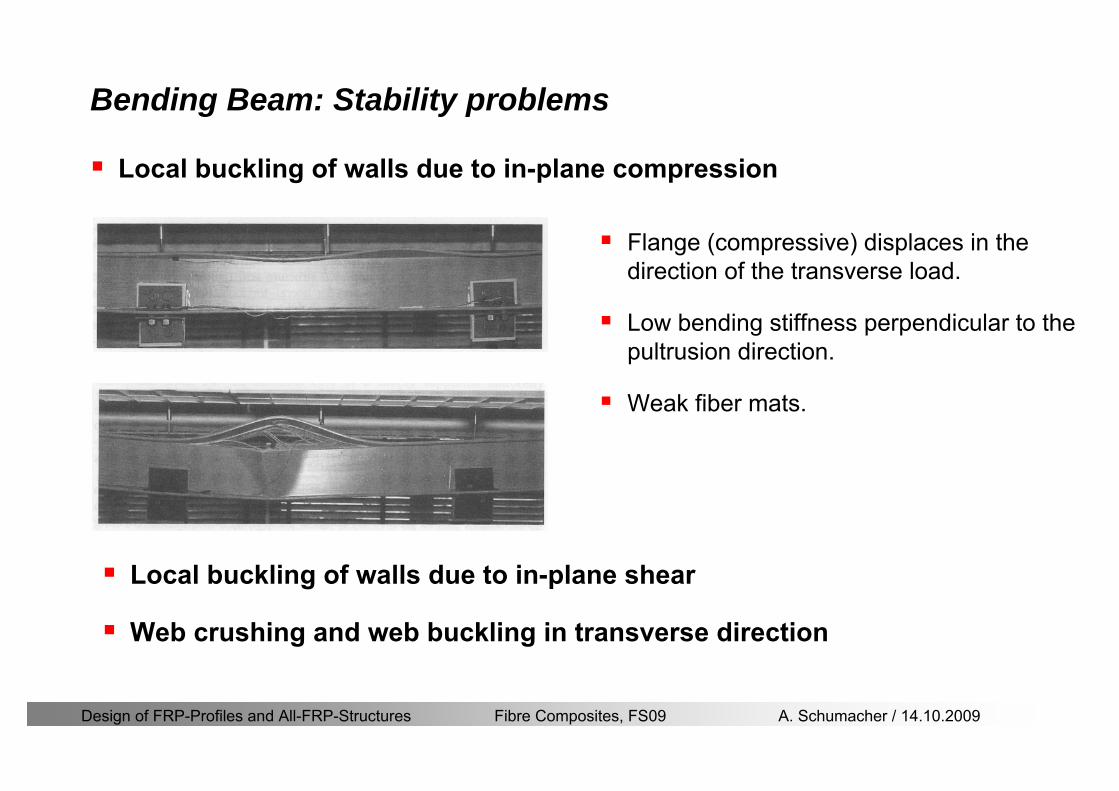
Design of FRP-Profiles and All-FRP-Structures Fibre Composites FS09 A Schumacher 14102009
Bending Beam Stability problems
Flange (compressive) displaces in the direction of the transverse load
Low bending stiffness perpendicular to the pultrusion direction
Weak fiber mats
Local buckling of walls due to in-plane compression
Local buckling of walls due to in-plane shear
Web crushing and web buckling in transverse direction
Design of FRP-Profiles and All-FRP-Structures Fibre Composites FS09 A Schumacher 14102009
Axial Members
Design of FRP-Profiles and All-FRP-Structures Fibre Composites FS09 A Schumacher 14102009
Axial Members Tension
Ultimate limit state under axial tension Nd
Serviceability limit state
Remark The critical aspect of axial members in tension are neither the serviceability nor the ultimate limit state Critical is the load transfer to the GFRP profile
0NdA
tm
fγ
degle
0deg
N LE Axδ sdot= sdot
Design of FRP-Profiles and All-FRP-Structures Fibre Composites FS09 A Schumacher 14102009
Axial Members Compression
Ultimate limit state under axial compression Nd
hellip maximal compressive load
hellip Euler load
hellip Buckling length for columns
hellip coefficient for Youngrsquos modulus = 13
cc
Euler
FNd F1 N
le+
c0degC
A fF
mγsdot
=
20
Euler 2
Nm E k
E IL
πγ
degsdot sdot=
sdot
kL
m Eγ
Design of FRP-Profiles and All-FRP-Structures Fibre Composites FS09 A Schumacher 14102009
Axial Members Compression
The influence of shear deformation should be considered but in the most cases the influence will be small (less than 5)
Local buckling should be considered for short columns
For more information on the various buckling modes and effects rarr see LP Kollaacuter 2003 Mechanics of composite structures
Global buckling Local buckling
Design of FRP-Profiles and All-FRP-Structures Fibre Composites FS09 A Schumacher 14102009
Connections
Design of FRP-Profiles and All-FRP-Structures Fibre Composites FS09 A Schumacher 14102009
Connections Introduction
Design of FRP-Profiles and All-FRP-Structures Fibre Composites FS09 A Schumacher 14102009
Connections Introduction
(from Eurocomp Design Code 1996)
Design of FRP-Profiles and All-FRP-Structures Fibre Composites FS09 A Schumacher 14102009
Connections Bolted joints
Bolts = Stress concentration in the profile and the bolt
It is necessary to ensure that the bolts and the profilecan withstand this concentrated local stress compression
It is necessary to ensure that the region surroundinga group of bolts will not be torn out of the profile
Basic failure modesin bolted shearconnections
bolt shear failure
Design of FRP-Profiles and All-FRP-Structures Fibre Composites FS09 A Schumacher 14102009
Connections Bolted joints
The design procedure is comparable to the one for steel connections but since there exist no standard GFRP material rarr each manufacturer has its own design rules for bolted joints
IMPORTANT REMARKS
The direction of pultrusion and the direction of the force is RELEVANT(anisotropic material)
Use stainless or galvanised steel
Do not cut threads in the composite material
Use screws with shafts
Design of FRP-Profiles and All-FRP-Structures Fibre Composites FS09 A Schumacher 14102009
Calculation of load bearing capacity of bolts
Shear in longitudinal direction (0deg)
Shear in transverse direction (90deg)
Tensile force
Minimum distances
Connections Bolted joints (Fiberline recommendations)
Design of FRP-Profiles and All-FRP-Structures Fibre Composites FS09 A Schumacher 14102009
Joint capacity tables available for shear and tension
m
150 MPa( 13)B d
d tP γsdot sdot=
=
Shear in longitudinal direction 0deg
m
70 MPa( 13)B d
d tP γsdot sdot=
=
Shear in transverse direction 90deg
Connections Bolted joints (Fiberline recommendations)
Design of FRP-Profiles and All-FRP-Structures Fibre Composites FS09 A Schumacher 14102009
Bolted connection in shear eg shear in longitudinal direction
Connections Bolted joints (Fiberline recommendations)
γmPBolt le dt720 MPaγmPBolt le dt240 MPa
γmPBolt le dt240 MPa γmPBolt le dt240 MPaγmPBolt le dt150 MPa
Design of FRP-Profiles and All-FRP-Structures Fibre Composites FS09 A Schumacher 14102009
Bolted connections in tension
Static conditions
Bolt Tearing of bolt in threaded cross-section
Laminate Shear fracture at rim of washer
Geometry and strength
Diameter of washer2d
Tensile strength of bolt hellipfyk
Shear strength of laminatehellipfτ
Thickness of laminatet
Stress area of the boltAs
Diameter of the boltd
s ykd m
A fP γ
sdotle
2d m
d t fP τπγ
sdot sdot sdot sdotle
Connections Bolted joints (Fiberline recommendations)
Design of FRP-Profiles and All-FRP-Structures Fibre Composites FS09 A Schumacher 14102009
Connections Bonded joints
Using an adhesive agent for joining profiles can have advantages
Easy to use easy to make aesthetic joints
Typically more rigid than bolted joints
Glued joints subjected to dynamic loads are good
But be careful hellipAdhesive agents have properties that depend on time temperature humidity hellip
Failure in glued joints takes place suddenly (brittle behaviour)
The load-bearing capacity is not proportional to the area which is glued
The design of bonded joints may be based onAnalytical models for plate-to-plate connections (see Eurocomp 1996 Design Code)
Design guidelines supplemented by testing
Finite element analysis
Design of FRP-Profiles and All-FRP-Structures Fibre Composites FS09 A Schumacher 14102009
Connections Bonded joints
A bonded joint has the following three primary failure modes
adhesive failure
cohesive failure of adhesive
cohesive failure of adherend
The design of any bonded joint shall satisfy the following conditions
allowable shear stress in the adhesive is not exceeded
allowable tensile (peel) stress in the adhesive is not exceeded
allowable through-thickness tensile stress of the adhesive is not exceeded
allowable in-plane shear stress of the adherend should not be exceeded
The calculation of the stresses has to be done very carefully Often calculations are supplemented by testing
Design of FRP-Profiles and All-FRP-Structures Fibre Composites FS09 A Schumacher 14102009
Connections Bonded joints
Different types of bonded joint configurations
Research on bonded joints for structuralapplications
Design of FRP-Profiles and All-FRP-Structures Fibre Composites FS09 A Schumacher 14102009
Connections Other joints
Brackets for assembly (Fiberline)
Custom pultruded connections
Design of FRP-Profiles and All-FRP-Structures Fibre Composites FS09 A Schumacher 14102009
GFRP Some final remarks
Perpendicular to the direction of pultrusion the material is WEAK and SOFTrarr avoid such loadings if possible
In order to use pultruded GFRP-profiles economically the design must be done in a clever way eg for bridges the railings should be used as part of the load-bearing structure
GFRP structures are very light rarr vibration problems may occur

Design of FRP-Profiles and All-FRP-Structures Fibre Composites FS09 A Schumacher 14102009
Axial Members
Design of FRP-Profiles and All-FRP-Structures Fibre Composites FS09 A Schumacher 14102009
Axial Members Tension
Ultimate limit state under axial tension Nd
Serviceability limit state
Remark The critical aspect of axial members in tension are neither the serviceability nor the ultimate limit state Critical is the load transfer to the GFRP profile
0NdA
tm
fγ
degle
0deg
N LE Axδ sdot= sdot
Design of FRP-Profiles and All-FRP-Structures Fibre Composites FS09 A Schumacher 14102009
Axial Members Compression
Ultimate limit state under axial compression Nd
hellip maximal compressive load
hellip Euler load
hellip Buckling length for columns
hellip coefficient for Youngrsquos modulus = 13
cc
Euler
FNd F1 N
le+
c0degC
A fF
mγsdot
=
20
Euler 2
Nm E k
E IL
πγ
degsdot sdot=
sdot
kL
m Eγ
Design of FRP-Profiles and All-FRP-Structures Fibre Composites FS09 A Schumacher 14102009
Axial Members Compression
The influence of shear deformation should be considered but in the most cases the influence will be small (less than 5)
Local buckling should be considered for short columns
For more information on the various buckling modes and effects rarr see LP Kollaacuter 2003 Mechanics of composite structures
Global buckling Local buckling
Design of FRP-Profiles and All-FRP-Structures Fibre Composites FS09 A Schumacher 14102009
Connections
Design of FRP-Profiles and All-FRP-Structures Fibre Composites FS09 A Schumacher 14102009
Connections Introduction
Design of FRP-Profiles and All-FRP-Structures Fibre Composites FS09 A Schumacher 14102009
Connections Introduction
(from Eurocomp Design Code 1996)
Design of FRP-Profiles and All-FRP-Structures Fibre Composites FS09 A Schumacher 14102009
Connections Bolted joints
Bolts = Stress concentration in the profile and the bolt
It is necessary to ensure that the bolts and the profilecan withstand this concentrated local stress compression
It is necessary to ensure that the region surroundinga group of bolts will not be torn out of the profile
Basic failure modesin bolted shearconnections
bolt shear failure
Design of FRP-Profiles and All-FRP-Structures Fibre Composites FS09 A Schumacher 14102009
Connections Bolted joints
The design procedure is comparable to the one for steel connections but since there exist no standard GFRP material rarr each manufacturer has its own design rules for bolted joints
IMPORTANT REMARKS
The direction of pultrusion and the direction of the force is RELEVANT(anisotropic material)
Use stainless or galvanised steel
Do not cut threads in the composite material
Use screws with shafts
Design of FRP-Profiles and All-FRP-Structures Fibre Composites FS09 A Schumacher 14102009
Calculation of load bearing capacity of bolts
Shear in longitudinal direction (0deg)
Shear in transverse direction (90deg)
Tensile force
Minimum distances
Connections Bolted joints (Fiberline recommendations)
Design of FRP-Profiles and All-FRP-Structures Fibre Composites FS09 A Schumacher 14102009
Joint capacity tables available for shear and tension
m
150 MPa( 13)B d
d tP γsdot sdot=
=
Shear in longitudinal direction 0deg
m
70 MPa( 13)B d
d tP γsdot sdot=
=
Shear in transverse direction 90deg
Connections Bolted joints (Fiberline recommendations)
Design of FRP-Profiles and All-FRP-Structures Fibre Composites FS09 A Schumacher 14102009
Bolted connection in shear eg shear in longitudinal direction
Connections Bolted joints (Fiberline recommendations)
γmPBolt le dt720 MPaγmPBolt le dt240 MPa
γmPBolt le dt240 MPa γmPBolt le dt240 MPaγmPBolt le dt150 MPa
Design of FRP-Profiles and All-FRP-Structures Fibre Composites FS09 A Schumacher 14102009
Bolted connections in tension
Static conditions
Bolt Tearing of bolt in threaded cross-section
Laminate Shear fracture at rim of washer
Geometry and strength
Diameter of washer2d
Tensile strength of bolt hellipfyk
Shear strength of laminatehellipfτ
Thickness of laminatet
Stress area of the boltAs
Diameter of the boltd
s ykd m
A fP γ
sdotle
2d m
d t fP τπγ
sdot sdot sdot sdotle
Connections Bolted joints (Fiberline recommendations)
Design of FRP-Profiles and All-FRP-Structures Fibre Composites FS09 A Schumacher 14102009
Connections Bonded joints
Using an adhesive agent for joining profiles can have advantages
Easy to use easy to make aesthetic joints
Typically more rigid than bolted joints
Glued joints subjected to dynamic loads are good
But be careful hellipAdhesive agents have properties that depend on time temperature humidity hellip
Failure in glued joints takes place suddenly (brittle behaviour)
The load-bearing capacity is not proportional to the area which is glued
The design of bonded joints may be based onAnalytical models for plate-to-plate connections (see Eurocomp 1996 Design Code)
Design guidelines supplemented by testing
Finite element analysis
Design of FRP-Profiles and All-FRP-Structures Fibre Composites FS09 A Schumacher 14102009
Connections Bonded joints
A bonded joint has the following three primary failure modes
adhesive failure
cohesive failure of adhesive
cohesive failure of adherend
The design of any bonded joint shall satisfy the following conditions
allowable shear stress in the adhesive is not exceeded
allowable tensile (peel) stress in the adhesive is not exceeded
allowable through-thickness tensile stress of the adhesive is not exceeded
allowable in-plane shear stress of the adherend should not be exceeded
The calculation of the stresses has to be done very carefully Often calculations are supplemented by testing
Design of FRP-Profiles and All-FRP-Structures Fibre Composites FS09 A Schumacher 14102009
Connections Bonded joints
Different types of bonded joint configurations
Research on bonded joints for structuralapplications
Design of FRP-Profiles and All-FRP-Structures Fibre Composites FS09 A Schumacher 14102009
Connections Other joints
Brackets for assembly (Fiberline)
Custom pultruded connections
Design of FRP-Profiles and All-FRP-Structures Fibre Composites FS09 A Schumacher 14102009
GFRP Some final remarks
Perpendicular to the direction of pultrusion the material is WEAK and SOFTrarr avoid such loadings if possible
In order to use pultruded GFRP-profiles economically the design must be done in a clever way eg for bridges the railings should be used as part of the load-bearing structure
GFRP structures are very light rarr vibration problems may occur
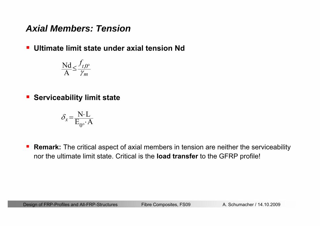
Design of FRP-Profiles and All-FRP-Structures Fibre Composites FS09 A Schumacher 14102009
Axial Members Tension
Ultimate limit state under axial tension Nd
Serviceability limit state
Remark The critical aspect of axial members in tension are neither the serviceability nor the ultimate limit state Critical is the load transfer to the GFRP profile
0NdA
tm
fγ
degle
0deg
N LE Axδ sdot= sdot
Design of FRP-Profiles and All-FRP-Structures Fibre Composites FS09 A Schumacher 14102009
Axial Members Compression
Ultimate limit state under axial compression Nd
hellip maximal compressive load
hellip Euler load
hellip Buckling length for columns
hellip coefficient for Youngrsquos modulus = 13
cc
Euler
FNd F1 N
le+
c0degC
A fF
mγsdot
=
20
Euler 2
Nm E k
E IL
πγ
degsdot sdot=
sdot
kL
m Eγ
Design of FRP-Profiles and All-FRP-Structures Fibre Composites FS09 A Schumacher 14102009
Axial Members Compression
The influence of shear deformation should be considered but in the most cases the influence will be small (less than 5)
Local buckling should be considered for short columns
For more information on the various buckling modes and effects rarr see LP Kollaacuter 2003 Mechanics of composite structures
Global buckling Local buckling
Design of FRP-Profiles and All-FRP-Structures Fibre Composites FS09 A Schumacher 14102009
Connections
Design of FRP-Profiles and All-FRP-Structures Fibre Composites FS09 A Schumacher 14102009
Connections Introduction
Design of FRP-Profiles and All-FRP-Structures Fibre Composites FS09 A Schumacher 14102009
Connections Introduction
(from Eurocomp Design Code 1996)
Design of FRP-Profiles and All-FRP-Structures Fibre Composites FS09 A Schumacher 14102009
Connections Bolted joints
Bolts = Stress concentration in the profile and the bolt
It is necessary to ensure that the bolts and the profilecan withstand this concentrated local stress compression
It is necessary to ensure that the region surroundinga group of bolts will not be torn out of the profile
Basic failure modesin bolted shearconnections
bolt shear failure
Design of FRP-Profiles and All-FRP-Structures Fibre Composites FS09 A Schumacher 14102009
Connections Bolted joints
The design procedure is comparable to the one for steel connections but since there exist no standard GFRP material rarr each manufacturer has its own design rules for bolted joints
IMPORTANT REMARKS
The direction of pultrusion and the direction of the force is RELEVANT(anisotropic material)
Use stainless or galvanised steel
Do not cut threads in the composite material
Use screws with shafts
Design of FRP-Profiles and All-FRP-Structures Fibre Composites FS09 A Schumacher 14102009
Calculation of load bearing capacity of bolts
Shear in longitudinal direction (0deg)
Shear in transverse direction (90deg)
Tensile force
Minimum distances
Connections Bolted joints (Fiberline recommendations)
Design of FRP-Profiles and All-FRP-Structures Fibre Composites FS09 A Schumacher 14102009
Joint capacity tables available for shear and tension
m
150 MPa( 13)B d
d tP γsdot sdot=
=
Shear in longitudinal direction 0deg
m
70 MPa( 13)B d
d tP γsdot sdot=
=
Shear in transverse direction 90deg
Connections Bolted joints (Fiberline recommendations)
Design of FRP-Profiles and All-FRP-Structures Fibre Composites FS09 A Schumacher 14102009
Bolted connection in shear eg shear in longitudinal direction
Connections Bolted joints (Fiberline recommendations)
γmPBolt le dt720 MPaγmPBolt le dt240 MPa
γmPBolt le dt240 MPa γmPBolt le dt240 MPaγmPBolt le dt150 MPa
Design of FRP-Profiles and All-FRP-Structures Fibre Composites FS09 A Schumacher 14102009
Bolted connections in tension
Static conditions
Bolt Tearing of bolt in threaded cross-section
Laminate Shear fracture at rim of washer
Geometry and strength
Diameter of washer2d
Tensile strength of bolt hellipfyk
Shear strength of laminatehellipfτ
Thickness of laminatet
Stress area of the boltAs
Diameter of the boltd
s ykd m
A fP γ
sdotle
2d m
d t fP τπγ
sdot sdot sdot sdotle
Connections Bolted joints (Fiberline recommendations)
Design of FRP-Profiles and All-FRP-Structures Fibre Composites FS09 A Schumacher 14102009
Connections Bonded joints
Using an adhesive agent for joining profiles can have advantages
Easy to use easy to make aesthetic joints
Typically more rigid than bolted joints
Glued joints subjected to dynamic loads are good
But be careful hellipAdhesive agents have properties that depend on time temperature humidity hellip
Failure in glued joints takes place suddenly (brittle behaviour)
The load-bearing capacity is not proportional to the area which is glued
The design of bonded joints may be based onAnalytical models for plate-to-plate connections (see Eurocomp 1996 Design Code)
Design guidelines supplemented by testing
Finite element analysis
Design of FRP-Profiles and All-FRP-Structures Fibre Composites FS09 A Schumacher 14102009
Connections Bonded joints
A bonded joint has the following three primary failure modes
adhesive failure
cohesive failure of adhesive
cohesive failure of adherend
The design of any bonded joint shall satisfy the following conditions
allowable shear stress in the adhesive is not exceeded
allowable tensile (peel) stress in the adhesive is not exceeded
allowable through-thickness tensile stress of the adhesive is not exceeded
allowable in-plane shear stress of the adherend should not be exceeded
The calculation of the stresses has to be done very carefully Often calculations are supplemented by testing
Design of FRP-Profiles and All-FRP-Structures Fibre Composites FS09 A Schumacher 14102009
Connections Bonded joints
Different types of bonded joint configurations
Research on bonded joints for structuralapplications
Design of FRP-Profiles and All-FRP-Structures Fibre Composites FS09 A Schumacher 14102009
Connections Other joints
Brackets for assembly (Fiberline)
Custom pultruded connections
Design of FRP-Profiles and All-FRP-Structures Fibre Composites FS09 A Schumacher 14102009
GFRP Some final remarks
Perpendicular to the direction of pultrusion the material is WEAK and SOFTrarr avoid such loadings if possible
In order to use pultruded GFRP-profiles economically the design must be done in a clever way eg for bridges the railings should be used as part of the load-bearing structure
GFRP structures are very light rarr vibration problems may occur
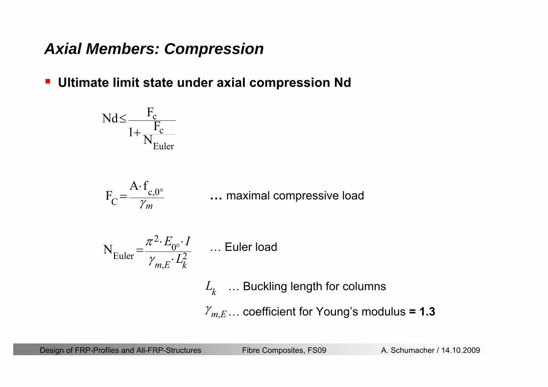
Design of FRP-Profiles and All-FRP-Structures Fibre Composites FS09 A Schumacher 14102009
Axial Members Compression
Ultimate limit state under axial compression Nd
hellip maximal compressive load
hellip Euler load
hellip Buckling length for columns
hellip coefficient for Youngrsquos modulus = 13
cc
Euler
FNd F1 N
le+
c0degC
A fF
mγsdot
=
20
Euler 2
Nm E k
E IL
πγ
degsdot sdot=
sdot
kL
m Eγ
Design of FRP-Profiles and All-FRP-Structures Fibre Composites FS09 A Schumacher 14102009
Axial Members Compression
The influence of shear deformation should be considered but in the most cases the influence will be small (less than 5)
Local buckling should be considered for short columns
For more information on the various buckling modes and effects rarr see LP Kollaacuter 2003 Mechanics of composite structures
Global buckling Local buckling
Design of FRP-Profiles and All-FRP-Structures Fibre Composites FS09 A Schumacher 14102009
Connections
Design of FRP-Profiles and All-FRP-Structures Fibre Composites FS09 A Schumacher 14102009
Connections Introduction
Design of FRP-Profiles and All-FRP-Structures Fibre Composites FS09 A Schumacher 14102009
Connections Introduction
(from Eurocomp Design Code 1996)
Design of FRP-Profiles and All-FRP-Structures Fibre Composites FS09 A Schumacher 14102009
Connections Bolted joints
Bolts = Stress concentration in the profile and the bolt
It is necessary to ensure that the bolts and the profilecan withstand this concentrated local stress compression
It is necessary to ensure that the region surroundinga group of bolts will not be torn out of the profile
Basic failure modesin bolted shearconnections
bolt shear failure
Design of FRP-Profiles and All-FRP-Structures Fibre Composites FS09 A Schumacher 14102009
Connections Bolted joints
The design procedure is comparable to the one for steel connections but since there exist no standard GFRP material rarr each manufacturer has its own design rules for bolted joints
IMPORTANT REMARKS
The direction of pultrusion and the direction of the force is RELEVANT(anisotropic material)
Use stainless or galvanised steel
Do not cut threads in the composite material
Use screws with shafts
Design of FRP-Profiles and All-FRP-Structures Fibre Composites FS09 A Schumacher 14102009
Calculation of load bearing capacity of bolts
Shear in longitudinal direction (0deg)
Shear in transverse direction (90deg)
Tensile force
Minimum distances
Connections Bolted joints (Fiberline recommendations)
Design of FRP-Profiles and All-FRP-Structures Fibre Composites FS09 A Schumacher 14102009
Joint capacity tables available for shear and tension
m
150 MPa( 13)B d
d tP γsdot sdot=
=
Shear in longitudinal direction 0deg
m
70 MPa( 13)B d
d tP γsdot sdot=
=
Shear in transverse direction 90deg
Connections Bolted joints (Fiberline recommendations)
Design of FRP-Profiles and All-FRP-Structures Fibre Composites FS09 A Schumacher 14102009
Bolted connection in shear eg shear in longitudinal direction
Connections Bolted joints (Fiberline recommendations)
γmPBolt le dt720 MPaγmPBolt le dt240 MPa
γmPBolt le dt240 MPa γmPBolt le dt240 MPaγmPBolt le dt150 MPa
Design of FRP-Profiles and All-FRP-Structures Fibre Composites FS09 A Schumacher 14102009
Bolted connections in tension
Static conditions
Bolt Tearing of bolt in threaded cross-section
Laminate Shear fracture at rim of washer
Geometry and strength
Diameter of washer2d
Tensile strength of bolt hellipfyk
Shear strength of laminatehellipfτ
Thickness of laminatet
Stress area of the boltAs
Diameter of the boltd
s ykd m
A fP γ
sdotle
2d m
d t fP τπγ
sdot sdot sdot sdotle
Connections Bolted joints (Fiberline recommendations)
Design of FRP-Profiles and All-FRP-Structures Fibre Composites FS09 A Schumacher 14102009
Connections Bonded joints
Using an adhesive agent for joining profiles can have advantages
Easy to use easy to make aesthetic joints
Typically more rigid than bolted joints
Glued joints subjected to dynamic loads are good
But be careful hellipAdhesive agents have properties that depend on time temperature humidity hellip
Failure in glued joints takes place suddenly (brittle behaviour)
The load-bearing capacity is not proportional to the area which is glued
The design of bonded joints may be based onAnalytical models for plate-to-plate connections (see Eurocomp 1996 Design Code)
Design guidelines supplemented by testing
Finite element analysis
Design of FRP-Profiles and All-FRP-Structures Fibre Composites FS09 A Schumacher 14102009
Connections Bonded joints
A bonded joint has the following three primary failure modes
adhesive failure
cohesive failure of adhesive
cohesive failure of adherend
The design of any bonded joint shall satisfy the following conditions
allowable shear stress in the adhesive is not exceeded
allowable tensile (peel) stress in the adhesive is not exceeded
allowable through-thickness tensile stress of the adhesive is not exceeded
allowable in-plane shear stress of the adherend should not be exceeded
The calculation of the stresses has to be done very carefully Often calculations are supplemented by testing
Design of FRP-Profiles and All-FRP-Structures Fibre Composites FS09 A Schumacher 14102009
Connections Bonded joints
Different types of bonded joint configurations
Research on bonded joints for structuralapplications
Design of FRP-Profiles and All-FRP-Structures Fibre Composites FS09 A Schumacher 14102009
Connections Other joints
Brackets for assembly (Fiberline)
Custom pultruded connections
Design of FRP-Profiles and All-FRP-Structures Fibre Composites FS09 A Schumacher 14102009
GFRP Some final remarks
Perpendicular to the direction of pultrusion the material is WEAK and SOFTrarr avoid such loadings if possible
In order to use pultruded GFRP-profiles economically the design must be done in a clever way eg for bridges the railings should be used as part of the load-bearing structure
GFRP structures are very light rarr vibration problems may occur
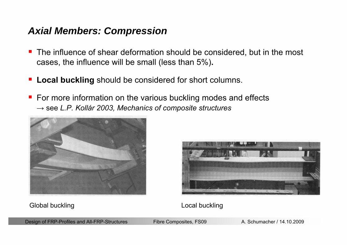
Design of FRP-Profiles and All-FRP-Structures Fibre Composites FS09 A Schumacher 14102009
Axial Members Compression
The influence of shear deformation should be considered but in the most cases the influence will be small (less than 5)
Local buckling should be considered for short columns
For more information on the various buckling modes and effects rarr see LP Kollaacuter 2003 Mechanics of composite structures
Global buckling Local buckling
Design of FRP-Profiles and All-FRP-Structures Fibre Composites FS09 A Schumacher 14102009
Connections
Design of FRP-Profiles and All-FRP-Structures Fibre Composites FS09 A Schumacher 14102009
Connections Introduction
Design of FRP-Profiles and All-FRP-Structures Fibre Composites FS09 A Schumacher 14102009
Connections Introduction
(from Eurocomp Design Code 1996)
Design of FRP-Profiles and All-FRP-Structures Fibre Composites FS09 A Schumacher 14102009
Connections Bolted joints
Bolts = Stress concentration in the profile and the bolt
It is necessary to ensure that the bolts and the profilecan withstand this concentrated local stress compression
It is necessary to ensure that the region surroundinga group of bolts will not be torn out of the profile
Basic failure modesin bolted shearconnections
bolt shear failure
Design of FRP-Profiles and All-FRP-Structures Fibre Composites FS09 A Schumacher 14102009
Connections Bolted joints
The design procedure is comparable to the one for steel connections but since there exist no standard GFRP material rarr each manufacturer has its own design rules for bolted joints
IMPORTANT REMARKS
The direction of pultrusion and the direction of the force is RELEVANT(anisotropic material)
Use stainless or galvanised steel
Do not cut threads in the composite material
Use screws with shafts
Design of FRP-Profiles and All-FRP-Structures Fibre Composites FS09 A Schumacher 14102009
Calculation of load bearing capacity of bolts
Shear in longitudinal direction (0deg)
Shear in transverse direction (90deg)
Tensile force
Minimum distances
Connections Bolted joints (Fiberline recommendations)
Design of FRP-Profiles and All-FRP-Structures Fibre Composites FS09 A Schumacher 14102009
Joint capacity tables available for shear and tension
m
150 MPa( 13)B d
d tP γsdot sdot=
=
Shear in longitudinal direction 0deg
m
70 MPa( 13)B d
d tP γsdot sdot=
=
Shear in transverse direction 90deg
Connections Bolted joints (Fiberline recommendations)
Design of FRP-Profiles and All-FRP-Structures Fibre Composites FS09 A Schumacher 14102009
Bolted connection in shear eg shear in longitudinal direction
Connections Bolted joints (Fiberline recommendations)
γmPBolt le dt720 MPaγmPBolt le dt240 MPa
γmPBolt le dt240 MPa γmPBolt le dt240 MPaγmPBolt le dt150 MPa
Design of FRP-Profiles and All-FRP-Structures Fibre Composites FS09 A Schumacher 14102009
Bolted connections in tension
Static conditions
Bolt Tearing of bolt in threaded cross-section
Laminate Shear fracture at rim of washer
Geometry and strength
Diameter of washer2d
Tensile strength of bolt hellipfyk
Shear strength of laminatehellipfτ
Thickness of laminatet
Stress area of the boltAs
Diameter of the boltd
s ykd m
A fP γ
sdotle
2d m
d t fP τπγ
sdot sdot sdot sdotle
Connections Bolted joints (Fiberline recommendations)
Design of FRP-Profiles and All-FRP-Structures Fibre Composites FS09 A Schumacher 14102009
Connections Bonded joints
Using an adhesive agent for joining profiles can have advantages
Easy to use easy to make aesthetic joints
Typically more rigid than bolted joints
Glued joints subjected to dynamic loads are good
But be careful hellipAdhesive agents have properties that depend on time temperature humidity hellip
Failure in glued joints takes place suddenly (brittle behaviour)
The load-bearing capacity is not proportional to the area which is glued
The design of bonded joints may be based onAnalytical models for plate-to-plate connections (see Eurocomp 1996 Design Code)
Design guidelines supplemented by testing
Finite element analysis
Design of FRP-Profiles and All-FRP-Structures Fibre Composites FS09 A Schumacher 14102009
Connections Bonded joints
A bonded joint has the following three primary failure modes
adhesive failure
cohesive failure of adhesive
cohesive failure of adherend
The design of any bonded joint shall satisfy the following conditions
allowable shear stress in the adhesive is not exceeded
allowable tensile (peel) stress in the adhesive is not exceeded
allowable through-thickness tensile stress of the adhesive is not exceeded
allowable in-plane shear stress of the adherend should not be exceeded
The calculation of the stresses has to be done very carefully Often calculations are supplemented by testing
Design of FRP-Profiles and All-FRP-Structures Fibre Composites FS09 A Schumacher 14102009
Connections Bonded joints
Different types of bonded joint configurations
Research on bonded joints for structuralapplications
Design of FRP-Profiles and All-FRP-Structures Fibre Composites FS09 A Schumacher 14102009
Connections Other joints
Brackets for assembly (Fiberline)
Custom pultruded connections
Design of FRP-Profiles and All-FRP-Structures Fibre Composites FS09 A Schumacher 14102009
GFRP Some final remarks
Perpendicular to the direction of pultrusion the material is WEAK and SOFTrarr avoid such loadings if possible
In order to use pultruded GFRP-profiles economically the design must be done in a clever way eg for bridges the railings should be used as part of the load-bearing structure
GFRP structures are very light rarr vibration problems may occur

Design of FRP-Profiles and All-FRP-Structures Fibre Composites FS09 A Schumacher 14102009
Connections
Design of FRP-Profiles and All-FRP-Structures Fibre Composites FS09 A Schumacher 14102009
Connections Introduction
Design of FRP-Profiles and All-FRP-Structures Fibre Composites FS09 A Schumacher 14102009
Connections Introduction
(from Eurocomp Design Code 1996)
Design of FRP-Profiles and All-FRP-Structures Fibre Composites FS09 A Schumacher 14102009
Connections Bolted joints
Bolts = Stress concentration in the profile and the bolt
It is necessary to ensure that the bolts and the profilecan withstand this concentrated local stress compression
It is necessary to ensure that the region surroundinga group of bolts will not be torn out of the profile
Basic failure modesin bolted shearconnections
bolt shear failure
Design of FRP-Profiles and All-FRP-Structures Fibre Composites FS09 A Schumacher 14102009
Connections Bolted joints
The design procedure is comparable to the one for steel connections but since there exist no standard GFRP material rarr each manufacturer has its own design rules for bolted joints
IMPORTANT REMARKS
The direction of pultrusion and the direction of the force is RELEVANT(anisotropic material)
Use stainless or galvanised steel
Do not cut threads in the composite material
Use screws with shafts
Design of FRP-Profiles and All-FRP-Structures Fibre Composites FS09 A Schumacher 14102009
Calculation of load bearing capacity of bolts
Shear in longitudinal direction (0deg)
Shear in transverse direction (90deg)
Tensile force
Minimum distances
Connections Bolted joints (Fiberline recommendations)
Design of FRP-Profiles and All-FRP-Structures Fibre Composites FS09 A Schumacher 14102009
Joint capacity tables available for shear and tension
m
150 MPa( 13)B d
d tP γsdot sdot=
=
Shear in longitudinal direction 0deg
m
70 MPa( 13)B d
d tP γsdot sdot=
=
Shear in transverse direction 90deg
Connections Bolted joints (Fiberline recommendations)
Design of FRP-Profiles and All-FRP-Structures Fibre Composites FS09 A Schumacher 14102009
Bolted connection in shear eg shear in longitudinal direction
Connections Bolted joints (Fiberline recommendations)
γmPBolt le dt720 MPaγmPBolt le dt240 MPa
γmPBolt le dt240 MPa γmPBolt le dt240 MPaγmPBolt le dt150 MPa
Design of FRP-Profiles and All-FRP-Structures Fibre Composites FS09 A Schumacher 14102009
Bolted connections in tension
Static conditions
Bolt Tearing of bolt in threaded cross-section
Laminate Shear fracture at rim of washer
Geometry and strength
Diameter of washer2d
Tensile strength of bolt hellipfyk
Shear strength of laminatehellipfτ
Thickness of laminatet
Stress area of the boltAs
Diameter of the boltd
s ykd m
A fP γ
sdotle
2d m
d t fP τπγ
sdot sdot sdot sdotle
Connections Bolted joints (Fiberline recommendations)
Design of FRP-Profiles and All-FRP-Structures Fibre Composites FS09 A Schumacher 14102009
Connections Bonded joints
Using an adhesive agent for joining profiles can have advantages
Easy to use easy to make aesthetic joints
Typically more rigid than bolted joints
Glued joints subjected to dynamic loads are good
But be careful hellipAdhesive agents have properties that depend on time temperature humidity hellip
Failure in glued joints takes place suddenly (brittle behaviour)
The load-bearing capacity is not proportional to the area which is glued
The design of bonded joints may be based onAnalytical models for plate-to-plate connections (see Eurocomp 1996 Design Code)
Design guidelines supplemented by testing
Finite element analysis
Design of FRP-Profiles and All-FRP-Structures Fibre Composites FS09 A Schumacher 14102009
Connections Bonded joints
A bonded joint has the following three primary failure modes
adhesive failure
cohesive failure of adhesive
cohesive failure of adherend
The design of any bonded joint shall satisfy the following conditions
allowable shear stress in the adhesive is not exceeded
allowable tensile (peel) stress in the adhesive is not exceeded
allowable through-thickness tensile stress of the adhesive is not exceeded
allowable in-plane shear stress of the adherend should not be exceeded
The calculation of the stresses has to be done very carefully Often calculations are supplemented by testing
Design of FRP-Profiles and All-FRP-Structures Fibre Composites FS09 A Schumacher 14102009
Connections Bonded joints
Different types of bonded joint configurations
Research on bonded joints for structuralapplications
Design of FRP-Profiles and All-FRP-Structures Fibre Composites FS09 A Schumacher 14102009
Connections Other joints
Brackets for assembly (Fiberline)
Custom pultruded connections
Design of FRP-Profiles and All-FRP-Structures Fibre Composites FS09 A Schumacher 14102009
GFRP Some final remarks
Perpendicular to the direction of pultrusion the material is WEAK and SOFTrarr avoid such loadings if possible
In order to use pultruded GFRP-profiles economically the design must be done in a clever way eg for bridges the railings should be used as part of the load-bearing structure
GFRP structures are very light rarr vibration problems may occur
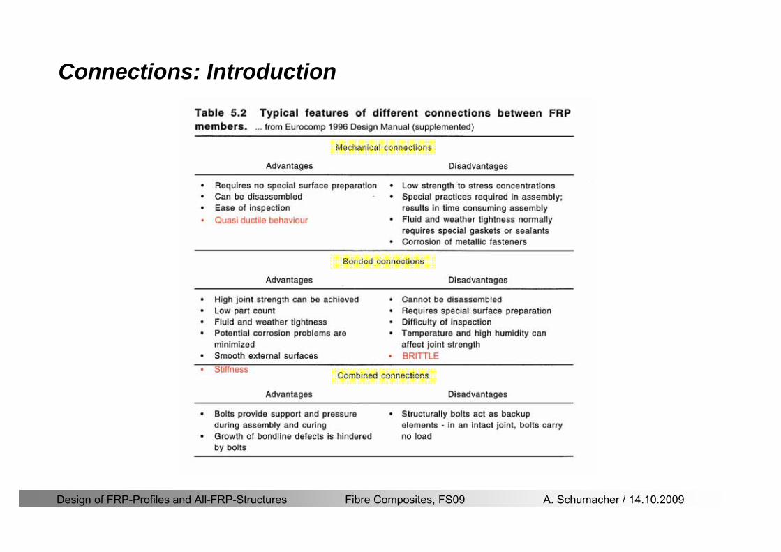
Design of FRP-Profiles and All-FRP-Structures Fibre Composites FS09 A Schumacher 14102009
Connections Introduction
Design of FRP-Profiles and All-FRP-Structures Fibre Composites FS09 A Schumacher 14102009
Connections Introduction
(from Eurocomp Design Code 1996)
Design of FRP-Profiles and All-FRP-Structures Fibre Composites FS09 A Schumacher 14102009
Connections Bolted joints
Bolts = Stress concentration in the profile and the bolt
It is necessary to ensure that the bolts and the profilecan withstand this concentrated local stress compression
It is necessary to ensure that the region surroundinga group of bolts will not be torn out of the profile
Basic failure modesin bolted shearconnections
bolt shear failure
Design of FRP-Profiles and All-FRP-Structures Fibre Composites FS09 A Schumacher 14102009
Connections Bolted joints
The design procedure is comparable to the one for steel connections but since there exist no standard GFRP material rarr each manufacturer has its own design rules for bolted joints
IMPORTANT REMARKS
The direction of pultrusion and the direction of the force is RELEVANT(anisotropic material)
Use stainless or galvanised steel
Do not cut threads in the composite material
Use screws with shafts
Design of FRP-Profiles and All-FRP-Structures Fibre Composites FS09 A Schumacher 14102009
Calculation of load bearing capacity of bolts
Shear in longitudinal direction (0deg)
Shear in transverse direction (90deg)
Tensile force
Minimum distances
Connections Bolted joints (Fiberline recommendations)
Design of FRP-Profiles and All-FRP-Structures Fibre Composites FS09 A Schumacher 14102009
Joint capacity tables available for shear and tension
m
150 MPa( 13)B d
d tP γsdot sdot=
=
Shear in longitudinal direction 0deg
m
70 MPa( 13)B d
d tP γsdot sdot=
=
Shear in transverse direction 90deg
Connections Bolted joints (Fiberline recommendations)
Design of FRP-Profiles and All-FRP-Structures Fibre Composites FS09 A Schumacher 14102009
Bolted connection in shear eg shear in longitudinal direction
Connections Bolted joints (Fiberline recommendations)
γmPBolt le dt720 MPaγmPBolt le dt240 MPa
γmPBolt le dt240 MPa γmPBolt le dt240 MPaγmPBolt le dt150 MPa
Design of FRP-Profiles and All-FRP-Structures Fibre Composites FS09 A Schumacher 14102009
Bolted connections in tension
Static conditions
Bolt Tearing of bolt in threaded cross-section
Laminate Shear fracture at rim of washer
Geometry and strength
Diameter of washer2d
Tensile strength of bolt hellipfyk
Shear strength of laminatehellipfτ
Thickness of laminatet
Stress area of the boltAs
Diameter of the boltd
s ykd m
A fP γ
sdotle
2d m
d t fP τπγ
sdot sdot sdot sdotle
Connections Bolted joints (Fiberline recommendations)
Design of FRP-Profiles and All-FRP-Structures Fibre Composites FS09 A Schumacher 14102009
Connections Bonded joints
Using an adhesive agent for joining profiles can have advantages
Easy to use easy to make aesthetic joints
Typically more rigid than bolted joints
Glued joints subjected to dynamic loads are good
But be careful hellipAdhesive agents have properties that depend on time temperature humidity hellip
Failure in glued joints takes place suddenly (brittle behaviour)
The load-bearing capacity is not proportional to the area which is glued
The design of bonded joints may be based onAnalytical models for plate-to-plate connections (see Eurocomp 1996 Design Code)
Design guidelines supplemented by testing
Finite element analysis
Design of FRP-Profiles and All-FRP-Structures Fibre Composites FS09 A Schumacher 14102009
Connections Bonded joints
A bonded joint has the following three primary failure modes
adhesive failure
cohesive failure of adhesive
cohesive failure of adherend
The design of any bonded joint shall satisfy the following conditions
allowable shear stress in the adhesive is not exceeded
allowable tensile (peel) stress in the adhesive is not exceeded
allowable through-thickness tensile stress of the adhesive is not exceeded
allowable in-plane shear stress of the adherend should not be exceeded
The calculation of the stresses has to be done very carefully Often calculations are supplemented by testing
Design of FRP-Profiles and All-FRP-Structures Fibre Composites FS09 A Schumacher 14102009
Connections Bonded joints
Different types of bonded joint configurations
Research on bonded joints for structuralapplications
Design of FRP-Profiles and All-FRP-Structures Fibre Composites FS09 A Schumacher 14102009
Connections Other joints
Brackets for assembly (Fiberline)
Custom pultruded connections
Design of FRP-Profiles and All-FRP-Structures Fibre Composites FS09 A Schumacher 14102009
GFRP Some final remarks
Perpendicular to the direction of pultrusion the material is WEAK and SOFTrarr avoid such loadings if possible
In order to use pultruded GFRP-profiles economically the design must be done in a clever way eg for bridges the railings should be used as part of the load-bearing structure
GFRP structures are very light rarr vibration problems may occur

Design of FRP-Profiles and All-FRP-Structures Fibre Composites FS09 A Schumacher 14102009
Connections Introduction
(from Eurocomp Design Code 1996)
Design of FRP-Profiles and All-FRP-Structures Fibre Composites FS09 A Schumacher 14102009
Connections Bolted joints
Bolts = Stress concentration in the profile and the bolt
It is necessary to ensure that the bolts and the profilecan withstand this concentrated local stress compression
It is necessary to ensure that the region surroundinga group of bolts will not be torn out of the profile
Basic failure modesin bolted shearconnections
bolt shear failure
Design of FRP-Profiles and All-FRP-Structures Fibre Composites FS09 A Schumacher 14102009
Connections Bolted joints
The design procedure is comparable to the one for steel connections but since there exist no standard GFRP material rarr each manufacturer has its own design rules for bolted joints
IMPORTANT REMARKS
The direction of pultrusion and the direction of the force is RELEVANT(anisotropic material)
Use stainless or galvanised steel
Do not cut threads in the composite material
Use screws with shafts
Design of FRP-Profiles and All-FRP-Structures Fibre Composites FS09 A Schumacher 14102009
Calculation of load bearing capacity of bolts
Shear in longitudinal direction (0deg)
Shear in transverse direction (90deg)
Tensile force
Minimum distances
Connections Bolted joints (Fiberline recommendations)
Design of FRP-Profiles and All-FRP-Structures Fibre Composites FS09 A Schumacher 14102009
Joint capacity tables available for shear and tension
m
150 MPa( 13)B d
d tP γsdot sdot=
=
Shear in longitudinal direction 0deg
m
70 MPa( 13)B d
d tP γsdot sdot=
=
Shear in transverse direction 90deg
Connections Bolted joints (Fiberline recommendations)
Design of FRP-Profiles and All-FRP-Structures Fibre Composites FS09 A Schumacher 14102009
Bolted connection in shear eg shear in longitudinal direction
Connections Bolted joints (Fiberline recommendations)
γmPBolt le dt720 MPaγmPBolt le dt240 MPa
γmPBolt le dt240 MPa γmPBolt le dt240 MPaγmPBolt le dt150 MPa
Design of FRP-Profiles and All-FRP-Structures Fibre Composites FS09 A Schumacher 14102009
Bolted connections in tension
Static conditions
Bolt Tearing of bolt in threaded cross-section
Laminate Shear fracture at rim of washer
Geometry and strength
Diameter of washer2d
Tensile strength of bolt hellipfyk
Shear strength of laminatehellipfτ
Thickness of laminatet
Stress area of the boltAs
Diameter of the boltd
s ykd m
A fP γ
sdotle
2d m
d t fP τπγ
sdot sdot sdot sdotle
Connections Bolted joints (Fiberline recommendations)
Design of FRP-Profiles and All-FRP-Structures Fibre Composites FS09 A Schumacher 14102009
Connections Bonded joints
Using an adhesive agent for joining profiles can have advantages
Easy to use easy to make aesthetic joints
Typically more rigid than bolted joints
Glued joints subjected to dynamic loads are good
But be careful hellipAdhesive agents have properties that depend on time temperature humidity hellip
Failure in glued joints takes place suddenly (brittle behaviour)
The load-bearing capacity is not proportional to the area which is glued
The design of bonded joints may be based onAnalytical models for plate-to-plate connections (see Eurocomp 1996 Design Code)
Design guidelines supplemented by testing
Finite element analysis
Design of FRP-Profiles and All-FRP-Structures Fibre Composites FS09 A Schumacher 14102009
Connections Bonded joints
A bonded joint has the following three primary failure modes
adhesive failure
cohesive failure of adhesive
cohesive failure of adherend
The design of any bonded joint shall satisfy the following conditions
allowable shear stress in the adhesive is not exceeded
allowable tensile (peel) stress in the adhesive is not exceeded
allowable through-thickness tensile stress of the adhesive is not exceeded
allowable in-plane shear stress of the adherend should not be exceeded
The calculation of the stresses has to be done very carefully Often calculations are supplemented by testing
Design of FRP-Profiles and All-FRP-Structures Fibre Composites FS09 A Schumacher 14102009
Connections Bonded joints
Different types of bonded joint configurations
Research on bonded joints for structuralapplications
Design of FRP-Profiles and All-FRP-Structures Fibre Composites FS09 A Schumacher 14102009
Connections Other joints
Brackets for assembly (Fiberline)
Custom pultruded connections
Design of FRP-Profiles and All-FRP-Structures Fibre Composites FS09 A Schumacher 14102009
GFRP Some final remarks
Perpendicular to the direction of pultrusion the material is WEAK and SOFTrarr avoid such loadings if possible
In order to use pultruded GFRP-profiles economically the design must be done in a clever way eg for bridges the railings should be used as part of the load-bearing structure
GFRP structures are very light rarr vibration problems may occur
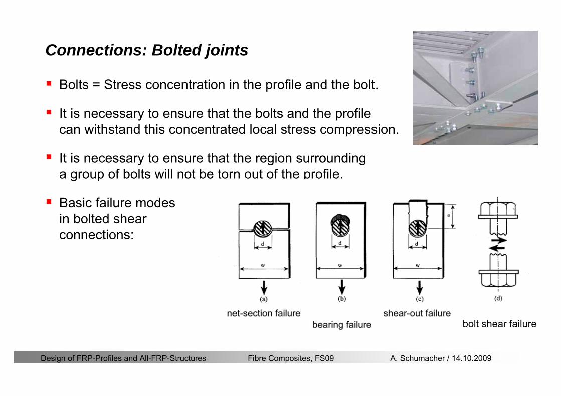
Design of FRP-Profiles and All-FRP-Structures Fibre Composites FS09 A Schumacher 14102009
Connections Bolted joints
Bolts = Stress concentration in the profile and the bolt
It is necessary to ensure that the bolts and the profilecan withstand this concentrated local stress compression
It is necessary to ensure that the region surroundinga group of bolts will not be torn out of the profile
Basic failure modesin bolted shearconnections
bolt shear failure
Design of FRP-Profiles and All-FRP-Structures Fibre Composites FS09 A Schumacher 14102009
Connections Bolted joints
The design procedure is comparable to the one for steel connections but since there exist no standard GFRP material rarr each manufacturer has its own design rules for bolted joints
IMPORTANT REMARKS
The direction of pultrusion and the direction of the force is RELEVANT(anisotropic material)
Use stainless or galvanised steel
Do not cut threads in the composite material
Use screws with shafts
Design of FRP-Profiles and All-FRP-Structures Fibre Composites FS09 A Schumacher 14102009
Calculation of load bearing capacity of bolts
Shear in longitudinal direction (0deg)
Shear in transverse direction (90deg)
Tensile force
Minimum distances
Connections Bolted joints (Fiberline recommendations)
Design of FRP-Profiles and All-FRP-Structures Fibre Composites FS09 A Schumacher 14102009
Joint capacity tables available for shear and tension
m
150 MPa( 13)B d
d tP γsdot sdot=
=
Shear in longitudinal direction 0deg
m
70 MPa( 13)B d
d tP γsdot sdot=
=
Shear in transverse direction 90deg
Connections Bolted joints (Fiberline recommendations)
Design of FRP-Profiles and All-FRP-Structures Fibre Composites FS09 A Schumacher 14102009
Bolted connection in shear eg shear in longitudinal direction
Connections Bolted joints (Fiberline recommendations)
γmPBolt le dt720 MPaγmPBolt le dt240 MPa
γmPBolt le dt240 MPa γmPBolt le dt240 MPaγmPBolt le dt150 MPa
Design of FRP-Profiles and All-FRP-Structures Fibre Composites FS09 A Schumacher 14102009
Bolted connections in tension
Static conditions
Bolt Tearing of bolt in threaded cross-section
Laminate Shear fracture at rim of washer
Geometry and strength
Diameter of washer2d
Tensile strength of bolt hellipfyk
Shear strength of laminatehellipfτ
Thickness of laminatet
Stress area of the boltAs
Diameter of the boltd
s ykd m
A fP γ
sdotle
2d m
d t fP τπγ
sdot sdot sdot sdotle
Connections Bolted joints (Fiberline recommendations)
Design of FRP-Profiles and All-FRP-Structures Fibre Composites FS09 A Schumacher 14102009
Connections Bonded joints
Using an adhesive agent for joining profiles can have advantages
Easy to use easy to make aesthetic joints
Typically more rigid than bolted joints
Glued joints subjected to dynamic loads are good
But be careful hellipAdhesive agents have properties that depend on time temperature humidity hellip
Failure in glued joints takes place suddenly (brittle behaviour)
The load-bearing capacity is not proportional to the area which is glued
The design of bonded joints may be based onAnalytical models for plate-to-plate connections (see Eurocomp 1996 Design Code)
Design guidelines supplemented by testing
Finite element analysis
Design of FRP-Profiles and All-FRP-Structures Fibre Composites FS09 A Schumacher 14102009
Connections Bonded joints
A bonded joint has the following three primary failure modes
adhesive failure
cohesive failure of adhesive
cohesive failure of adherend
The design of any bonded joint shall satisfy the following conditions
allowable shear stress in the adhesive is not exceeded
allowable tensile (peel) stress in the adhesive is not exceeded
allowable through-thickness tensile stress of the adhesive is not exceeded
allowable in-plane shear stress of the adherend should not be exceeded
The calculation of the stresses has to be done very carefully Often calculations are supplemented by testing
Design of FRP-Profiles and All-FRP-Structures Fibre Composites FS09 A Schumacher 14102009
Connections Bonded joints
Different types of bonded joint configurations
Research on bonded joints for structuralapplications
Design of FRP-Profiles and All-FRP-Structures Fibre Composites FS09 A Schumacher 14102009
Connections Other joints
Brackets for assembly (Fiberline)
Custom pultruded connections
Design of FRP-Profiles and All-FRP-Structures Fibre Composites FS09 A Schumacher 14102009
GFRP Some final remarks
Perpendicular to the direction of pultrusion the material is WEAK and SOFTrarr avoid such loadings if possible
In order to use pultruded GFRP-profiles economically the design must be done in a clever way eg for bridges the railings should be used as part of the load-bearing structure
GFRP structures are very light rarr vibration problems may occur
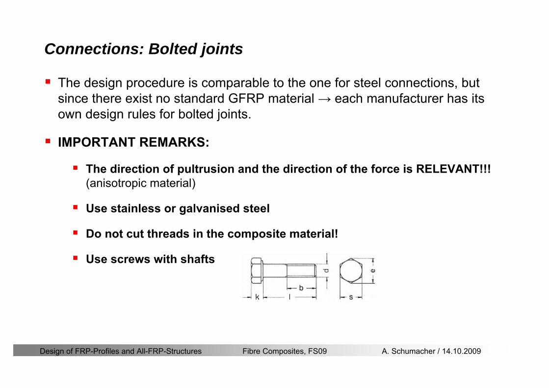
Design of FRP-Profiles and All-FRP-Structures Fibre Composites FS09 A Schumacher 14102009
Connections Bolted joints
The design procedure is comparable to the one for steel connections but since there exist no standard GFRP material rarr each manufacturer has its own design rules for bolted joints
IMPORTANT REMARKS
The direction of pultrusion and the direction of the force is RELEVANT(anisotropic material)
Use stainless or galvanised steel
Do not cut threads in the composite material
Use screws with shafts
Design of FRP-Profiles and All-FRP-Structures Fibre Composites FS09 A Schumacher 14102009
Calculation of load bearing capacity of bolts
Shear in longitudinal direction (0deg)
Shear in transverse direction (90deg)
Tensile force
Minimum distances
Connections Bolted joints (Fiberline recommendations)
Design of FRP-Profiles and All-FRP-Structures Fibre Composites FS09 A Schumacher 14102009
Joint capacity tables available for shear and tension
m
150 MPa( 13)B d
d tP γsdot sdot=
=
Shear in longitudinal direction 0deg
m
70 MPa( 13)B d
d tP γsdot sdot=
=
Shear in transverse direction 90deg
Connections Bolted joints (Fiberline recommendations)
Design of FRP-Profiles and All-FRP-Structures Fibre Composites FS09 A Schumacher 14102009
Bolted connection in shear eg shear in longitudinal direction
Connections Bolted joints (Fiberline recommendations)
γmPBolt le dt720 MPaγmPBolt le dt240 MPa
γmPBolt le dt240 MPa γmPBolt le dt240 MPaγmPBolt le dt150 MPa
Design of FRP-Profiles and All-FRP-Structures Fibre Composites FS09 A Schumacher 14102009
Bolted connections in tension
Static conditions
Bolt Tearing of bolt in threaded cross-section
Laminate Shear fracture at rim of washer
Geometry and strength
Diameter of washer2d
Tensile strength of bolt hellipfyk
Shear strength of laminatehellipfτ
Thickness of laminatet
Stress area of the boltAs
Diameter of the boltd
s ykd m
A fP γ
sdotle
2d m
d t fP τπγ
sdot sdot sdot sdotle
Connections Bolted joints (Fiberline recommendations)
Design of FRP-Profiles and All-FRP-Structures Fibre Composites FS09 A Schumacher 14102009
Connections Bonded joints
Using an adhesive agent for joining profiles can have advantages
Easy to use easy to make aesthetic joints
Typically more rigid than bolted joints
Glued joints subjected to dynamic loads are good
But be careful hellipAdhesive agents have properties that depend on time temperature humidity hellip
Failure in glued joints takes place suddenly (brittle behaviour)
The load-bearing capacity is not proportional to the area which is glued
The design of bonded joints may be based onAnalytical models for plate-to-plate connections (see Eurocomp 1996 Design Code)
Design guidelines supplemented by testing
Finite element analysis
Design of FRP-Profiles and All-FRP-Structures Fibre Composites FS09 A Schumacher 14102009
Connections Bonded joints
A bonded joint has the following three primary failure modes
adhesive failure
cohesive failure of adhesive
cohesive failure of adherend
The design of any bonded joint shall satisfy the following conditions
allowable shear stress in the adhesive is not exceeded
allowable tensile (peel) stress in the adhesive is not exceeded
allowable through-thickness tensile stress of the adhesive is not exceeded
allowable in-plane shear stress of the adherend should not be exceeded
The calculation of the stresses has to be done very carefully Often calculations are supplemented by testing
Design of FRP-Profiles and All-FRP-Structures Fibre Composites FS09 A Schumacher 14102009
Connections Bonded joints
Different types of bonded joint configurations
Research on bonded joints for structuralapplications
Design of FRP-Profiles and All-FRP-Structures Fibre Composites FS09 A Schumacher 14102009
Connections Other joints
Brackets for assembly (Fiberline)
Custom pultruded connections
Design of FRP-Profiles and All-FRP-Structures Fibre Composites FS09 A Schumacher 14102009
GFRP Some final remarks
Perpendicular to the direction of pultrusion the material is WEAK and SOFTrarr avoid such loadings if possible
In order to use pultruded GFRP-profiles economically the design must be done in a clever way eg for bridges the railings should be used as part of the load-bearing structure
GFRP structures are very light rarr vibration problems may occur
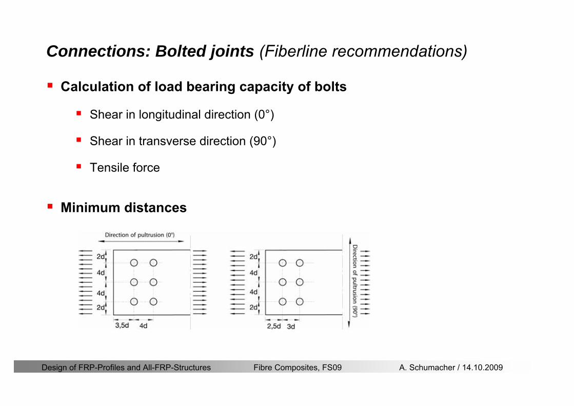
Design of FRP-Profiles and All-FRP-Structures Fibre Composites FS09 A Schumacher 14102009
Calculation of load bearing capacity of bolts
Shear in longitudinal direction (0deg)
Shear in transverse direction (90deg)
Tensile force
Minimum distances
Connections Bolted joints (Fiberline recommendations)
Design of FRP-Profiles and All-FRP-Structures Fibre Composites FS09 A Schumacher 14102009
Joint capacity tables available for shear and tension
m
150 MPa( 13)B d
d tP γsdot sdot=
=
Shear in longitudinal direction 0deg
m
70 MPa( 13)B d
d tP γsdot sdot=
=
Shear in transverse direction 90deg
Connections Bolted joints (Fiberline recommendations)
Design of FRP-Profiles and All-FRP-Structures Fibre Composites FS09 A Schumacher 14102009
Bolted connection in shear eg shear in longitudinal direction
Connections Bolted joints (Fiberline recommendations)
γmPBolt le dt720 MPaγmPBolt le dt240 MPa
γmPBolt le dt240 MPa γmPBolt le dt240 MPaγmPBolt le dt150 MPa
Design of FRP-Profiles and All-FRP-Structures Fibre Composites FS09 A Schumacher 14102009
Bolted connections in tension
Static conditions
Bolt Tearing of bolt in threaded cross-section
Laminate Shear fracture at rim of washer
Geometry and strength
Diameter of washer2d
Tensile strength of bolt hellipfyk
Shear strength of laminatehellipfτ
Thickness of laminatet
Stress area of the boltAs
Diameter of the boltd
s ykd m
A fP γ
sdotle
2d m
d t fP τπγ
sdot sdot sdot sdotle
Connections Bolted joints (Fiberline recommendations)
Design of FRP-Profiles and All-FRP-Structures Fibre Composites FS09 A Schumacher 14102009
Connections Bonded joints
Using an adhesive agent for joining profiles can have advantages
Easy to use easy to make aesthetic joints
Typically more rigid than bolted joints
Glued joints subjected to dynamic loads are good
But be careful hellipAdhesive agents have properties that depend on time temperature humidity hellip
Failure in glued joints takes place suddenly (brittle behaviour)
The load-bearing capacity is not proportional to the area which is glued
The design of bonded joints may be based onAnalytical models for plate-to-plate connections (see Eurocomp 1996 Design Code)
Design guidelines supplemented by testing
Finite element analysis
Design of FRP-Profiles and All-FRP-Structures Fibre Composites FS09 A Schumacher 14102009
Connections Bonded joints
A bonded joint has the following three primary failure modes
adhesive failure
cohesive failure of adhesive
cohesive failure of adherend
The design of any bonded joint shall satisfy the following conditions
allowable shear stress in the adhesive is not exceeded
allowable tensile (peel) stress in the adhesive is not exceeded
allowable through-thickness tensile stress of the adhesive is not exceeded
allowable in-plane shear stress of the adherend should not be exceeded
The calculation of the stresses has to be done very carefully Often calculations are supplemented by testing
Design of FRP-Profiles and All-FRP-Structures Fibre Composites FS09 A Schumacher 14102009
Connections Bonded joints
Different types of bonded joint configurations
Research on bonded joints for structuralapplications
Design of FRP-Profiles and All-FRP-Structures Fibre Composites FS09 A Schumacher 14102009
Connections Other joints
Brackets for assembly (Fiberline)
Custom pultruded connections
Design of FRP-Profiles and All-FRP-Structures Fibre Composites FS09 A Schumacher 14102009
GFRP Some final remarks
Perpendicular to the direction of pultrusion the material is WEAK and SOFTrarr avoid such loadings if possible
In order to use pultruded GFRP-profiles economically the design must be done in a clever way eg for bridges the railings should be used as part of the load-bearing structure
GFRP structures are very light rarr vibration problems may occur
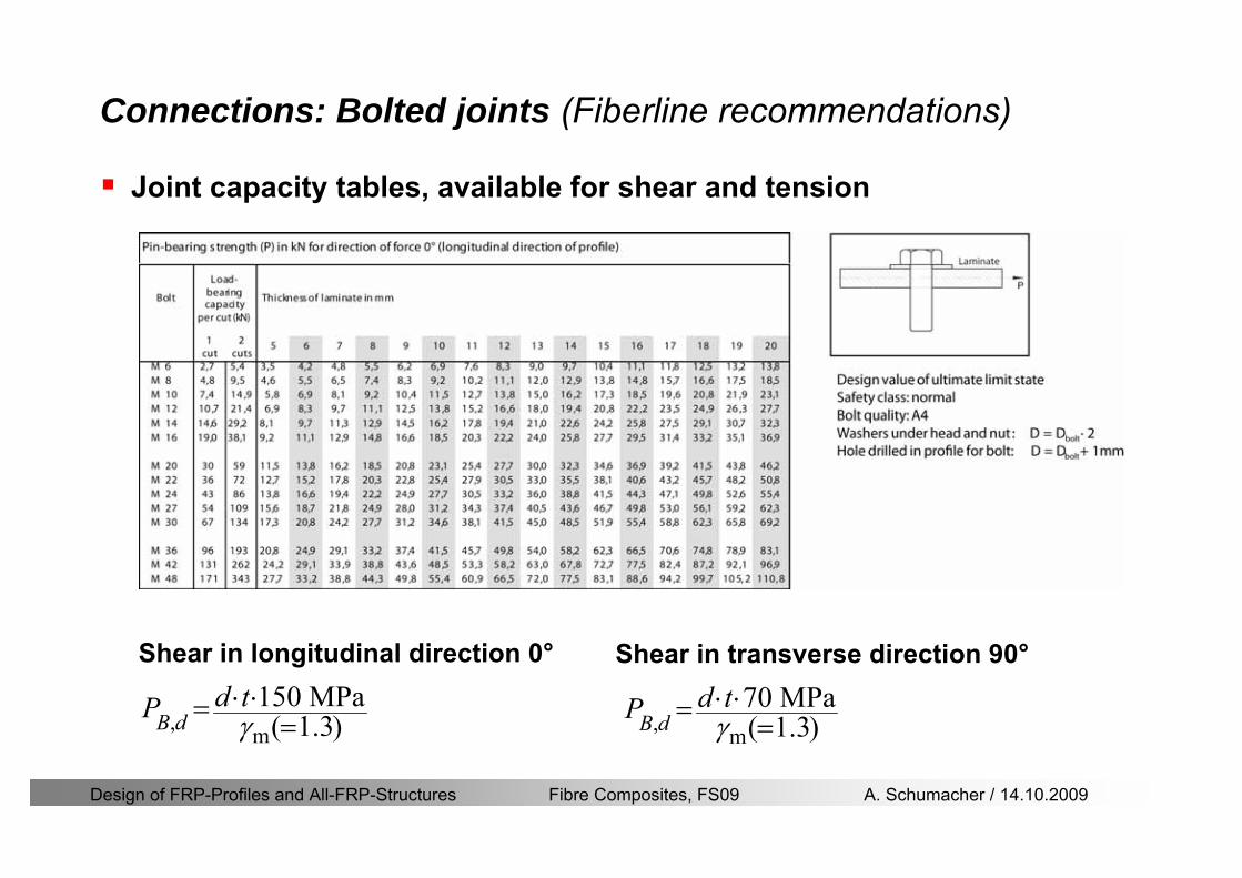
Design of FRP-Profiles and All-FRP-Structures Fibre Composites FS09 A Schumacher 14102009
Joint capacity tables available for shear and tension
m
150 MPa( 13)B d
d tP γsdot sdot=
=
Shear in longitudinal direction 0deg
m
70 MPa( 13)B d
d tP γsdot sdot=
=
Shear in transverse direction 90deg
Connections Bolted joints (Fiberline recommendations)
Design of FRP-Profiles and All-FRP-Structures Fibre Composites FS09 A Schumacher 14102009
Bolted connection in shear eg shear in longitudinal direction
Connections Bolted joints (Fiberline recommendations)
γmPBolt le dt720 MPaγmPBolt le dt240 MPa
γmPBolt le dt240 MPa γmPBolt le dt240 MPaγmPBolt le dt150 MPa
Design of FRP-Profiles and All-FRP-Structures Fibre Composites FS09 A Schumacher 14102009
Bolted connections in tension
Static conditions
Bolt Tearing of bolt in threaded cross-section
Laminate Shear fracture at rim of washer
Geometry and strength
Diameter of washer2d
Tensile strength of bolt hellipfyk
Shear strength of laminatehellipfτ
Thickness of laminatet
Stress area of the boltAs
Diameter of the boltd
s ykd m
A fP γ
sdotle
2d m
d t fP τπγ
sdot sdot sdot sdotle
Connections Bolted joints (Fiberline recommendations)
Design of FRP-Profiles and All-FRP-Structures Fibre Composites FS09 A Schumacher 14102009
Connections Bonded joints
Using an adhesive agent for joining profiles can have advantages
Easy to use easy to make aesthetic joints
Typically more rigid than bolted joints
Glued joints subjected to dynamic loads are good
But be careful hellipAdhesive agents have properties that depend on time temperature humidity hellip
Failure in glued joints takes place suddenly (brittle behaviour)
The load-bearing capacity is not proportional to the area which is glued
The design of bonded joints may be based onAnalytical models for plate-to-plate connections (see Eurocomp 1996 Design Code)
Design guidelines supplemented by testing
Finite element analysis
Design of FRP-Profiles and All-FRP-Structures Fibre Composites FS09 A Schumacher 14102009
Connections Bonded joints
A bonded joint has the following three primary failure modes
adhesive failure
cohesive failure of adhesive
cohesive failure of adherend
The design of any bonded joint shall satisfy the following conditions
allowable shear stress in the adhesive is not exceeded
allowable tensile (peel) stress in the adhesive is not exceeded
allowable through-thickness tensile stress of the adhesive is not exceeded
allowable in-plane shear stress of the adherend should not be exceeded
The calculation of the stresses has to be done very carefully Often calculations are supplemented by testing
Design of FRP-Profiles and All-FRP-Structures Fibre Composites FS09 A Schumacher 14102009
Connections Bonded joints
Different types of bonded joint configurations
Research on bonded joints for structuralapplications
Design of FRP-Profiles and All-FRP-Structures Fibre Composites FS09 A Schumacher 14102009
Connections Other joints
Brackets for assembly (Fiberline)
Custom pultruded connections
Design of FRP-Profiles and All-FRP-Structures Fibre Composites FS09 A Schumacher 14102009
GFRP Some final remarks
Perpendicular to the direction of pultrusion the material is WEAK and SOFTrarr avoid such loadings if possible
In order to use pultruded GFRP-profiles economically the design must be done in a clever way eg for bridges the railings should be used as part of the load-bearing structure
GFRP structures are very light rarr vibration problems may occur
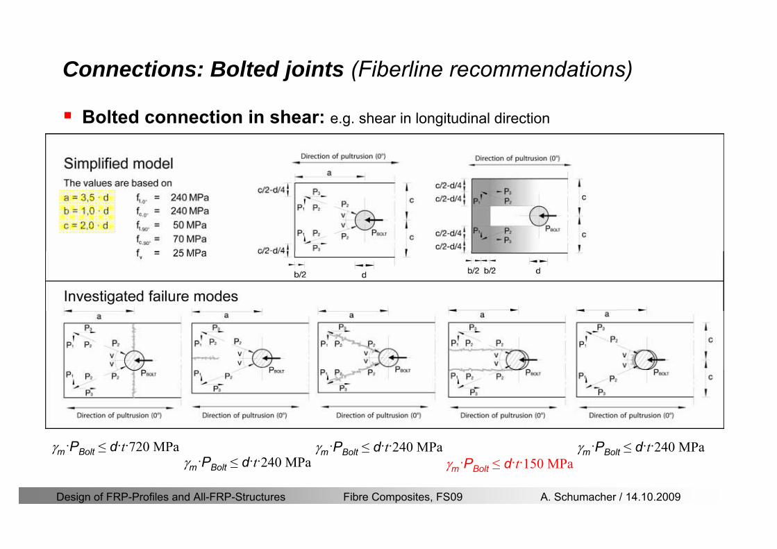
Design of FRP-Profiles and All-FRP-Structures Fibre Composites FS09 A Schumacher 14102009
Bolted connection in shear eg shear in longitudinal direction
Connections Bolted joints (Fiberline recommendations)
γmPBolt le dt720 MPaγmPBolt le dt240 MPa
γmPBolt le dt240 MPa γmPBolt le dt240 MPaγmPBolt le dt150 MPa
Design of FRP-Profiles and All-FRP-Structures Fibre Composites FS09 A Schumacher 14102009
Bolted connections in tension
Static conditions
Bolt Tearing of bolt in threaded cross-section
Laminate Shear fracture at rim of washer
Geometry and strength
Diameter of washer2d
Tensile strength of bolt hellipfyk
Shear strength of laminatehellipfτ
Thickness of laminatet
Stress area of the boltAs
Diameter of the boltd
s ykd m
A fP γ
sdotle
2d m
d t fP τπγ
sdot sdot sdot sdotle
Connections Bolted joints (Fiberline recommendations)
Design of FRP-Profiles and All-FRP-Structures Fibre Composites FS09 A Schumacher 14102009
Connections Bonded joints
Using an adhesive agent for joining profiles can have advantages
Easy to use easy to make aesthetic joints
Typically more rigid than bolted joints
Glued joints subjected to dynamic loads are good
But be careful hellipAdhesive agents have properties that depend on time temperature humidity hellip
Failure in glued joints takes place suddenly (brittle behaviour)
The load-bearing capacity is not proportional to the area which is glued
The design of bonded joints may be based onAnalytical models for plate-to-plate connections (see Eurocomp 1996 Design Code)
Design guidelines supplemented by testing
Finite element analysis
Design of FRP-Profiles and All-FRP-Structures Fibre Composites FS09 A Schumacher 14102009
Connections Bonded joints
A bonded joint has the following three primary failure modes
adhesive failure
cohesive failure of adhesive
cohesive failure of adherend
The design of any bonded joint shall satisfy the following conditions
allowable shear stress in the adhesive is not exceeded
allowable tensile (peel) stress in the adhesive is not exceeded
allowable through-thickness tensile stress of the adhesive is not exceeded
allowable in-plane shear stress of the adherend should not be exceeded
The calculation of the stresses has to be done very carefully Often calculations are supplemented by testing
Design of FRP-Profiles and All-FRP-Structures Fibre Composites FS09 A Schumacher 14102009
Connections Bonded joints
Different types of bonded joint configurations
Research on bonded joints for structuralapplications
Design of FRP-Profiles and All-FRP-Structures Fibre Composites FS09 A Schumacher 14102009
Connections Other joints
Brackets for assembly (Fiberline)
Custom pultruded connections
Design of FRP-Profiles and All-FRP-Structures Fibre Composites FS09 A Schumacher 14102009
GFRP Some final remarks
Perpendicular to the direction of pultrusion the material is WEAK and SOFTrarr avoid such loadings if possible
In order to use pultruded GFRP-profiles economically the design must be done in a clever way eg for bridges the railings should be used as part of the load-bearing structure
GFRP structures are very light rarr vibration problems may occur
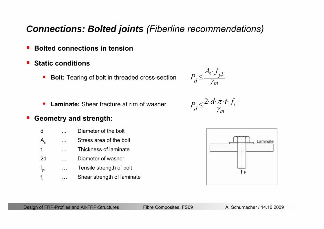
Design of FRP-Profiles and All-FRP-Structures Fibre Composites FS09 A Schumacher 14102009
Bolted connections in tension
Static conditions
Bolt Tearing of bolt in threaded cross-section
Laminate Shear fracture at rim of washer
Geometry and strength
Diameter of washer2d
Tensile strength of bolt hellipfyk
Shear strength of laminatehellipfτ
Thickness of laminatet
Stress area of the boltAs
Diameter of the boltd
s ykd m
A fP γ
sdotle
2d m
d t fP τπγ
sdot sdot sdot sdotle
Connections Bolted joints (Fiberline recommendations)
Design of FRP-Profiles and All-FRP-Structures Fibre Composites FS09 A Schumacher 14102009
Connections Bonded joints
Using an adhesive agent for joining profiles can have advantages
Easy to use easy to make aesthetic joints
Typically more rigid than bolted joints
Glued joints subjected to dynamic loads are good
But be careful hellipAdhesive agents have properties that depend on time temperature humidity hellip
Failure in glued joints takes place suddenly (brittle behaviour)
The load-bearing capacity is not proportional to the area which is glued
The design of bonded joints may be based onAnalytical models for plate-to-plate connections (see Eurocomp 1996 Design Code)
Design guidelines supplemented by testing
Finite element analysis
Design of FRP-Profiles and All-FRP-Structures Fibre Composites FS09 A Schumacher 14102009
Connections Bonded joints
A bonded joint has the following three primary failure modes
adhesive failure
cohesive failure of adhesive
cohesive failure of adherend
The design of any bonded joint shall satisfy the following conditions
allowable shear stress in the adhesive is not exceeded
allowable tensile (peel) stress in the adhesive is not exceeded
allowable through-thickness tensile stress of the adhesive is not exceeded
allowable in-plane shear stress of the adherend should not be exceeded
The calculation of the stresses has to be done very carefully Often calculations are supplemented by testing
Design of FRP-Profiles and All-FRP-Structures Fibre Composites FS09 A Schumacher 14102009
Connections Bonded joints
Different types of bonded joint configurations
Research on bonded joints for structuralapplications
Design of FRP-Profiles and All-FRP-Structures Fibre Composites FS09 A Schumacher 14102009
Connections Other joints
Brackets for assembly (Fiberline)
Custom pultruded connections
Design of FRP-Profiles and All-FRP-Structures Fibre Composites FS09 A Schumacher 14102009
GFRP Some final remarks
Perpendicular to the direction of pultrusion the material is WEAK and SOFTrarr avoid such loadings if possible
In order to use pultruded GFRP-profiles economically the design must be done in a clever way eg for bridges the railings should be used as part of the load-bearing structure
GFRP structures are very light rarr vibration problems may occur
Design of FRP-Profiles and All-FRP-Structures Fibre Composites FS09 A Schumacher 14102009
Connections Bonded joints
A bonded joint has the following three primary failure modes
adhesive failure
cohesive failure of adhesive
cohesive failure of adherend
The design of any bonded joint shall satisfy the following conditions
allowable shear stress in the adhesive is not exceeded
allowable tensile (peel) stress in the adhesive is not exceeded
allowable through-thickness tensile stress of the adhesive is not exceeded
allowable in-plane shear stress of the adherend should not be exceeded
The calculation of the stresses has to be done very carefully Often calculations are supplemented by testing
Design of FRP-Profiles and All-FRP-Structures Fibre Composites FS09 A Schumacher 14102009
Connections Bonded joints
Different types of bonded joint configurations
Research on bonded joints for structuralapplications
Design of FRP-Profiles and All-FRP-Structures Fibre Composites FS09 A Schumacher 14102009
Connections Other joints
Brackets for assembly (Fiberline)
Custom pultruded connections
Design of FRP-Profiles and All-FRP-Structures Fibre Composites FS09 A Schumacher 14102009
GFRP Some final remarks
Perpendicular to the direction of pultrusion the material is WEAK and SOFTrarr avoid such loadings if possible
In order to use pultruded GFRP-profiles economically the design must be done in a clever way eg for bridges the railings should be used as part of the load-bearing structure
GFRP structures are very light rarr vibration problems may occur
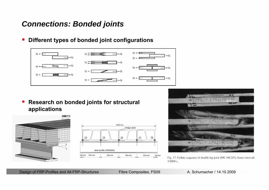
Design of FRP-Profiles and All-FRP-Structures Fibre Composites FS09 A Schumacher 14102009
Connections Bonded joints
Different types of bonded joint configurations
Research on bonded joints for structuralapplications
Design of FRP-Profiles and All-FRP-Structures Fibre Composites FS09 A Schumacher 14102009
Connections Other joints
Brackets for assembly (Fiberline)
Custom pultruded connections
Design of FRP-Profiles and All-FRP-Structures Fibre Composites FS09 A Schumacher 14102009
GFRP Some final remarks
Perpendicular to the direction of pultrusion the material is WEAK and SOFTrarr avoid such loadings if possible
In order to use pultruded GFRP-profiles economically the design must be done in a clever way eg for bridges the railings should be used as part of the load-bearing structure
GFRP structures are very light rarr vibration problems may occur
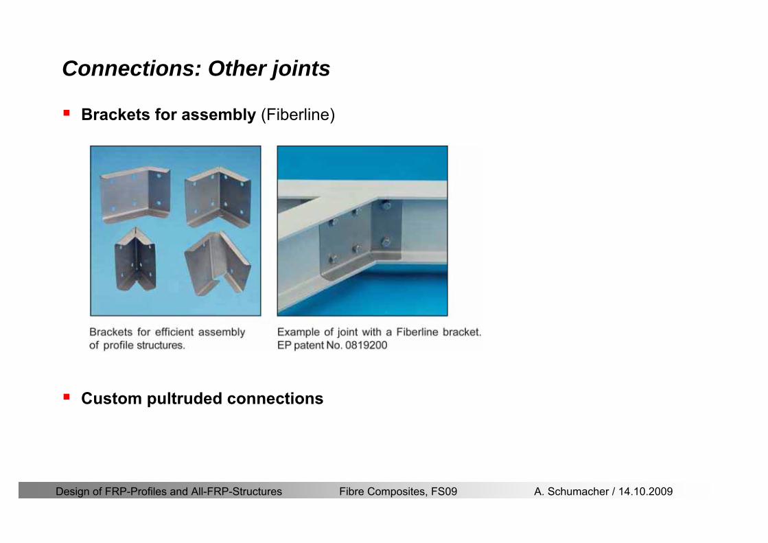
Design of FRP-Profiles and All-FRP-Structures Fibre Composites FS09 A Schumacher 14102009
Connections Other joints
Brackets for assembly (Fiberline)
Custom pultruded connections
Design of FRP-Profiles and All-FRP-Structures Fibre Composites FS09 A Schumacher 14102009
GFRP Some final remarks
Perpendicular to the direction of pultrusion the material is WEAK and SOFTrarr avoid such loadings if possible
In order to use pultruded GFRP-profiles economically the design must be done in a clever way eg for bridges the railings should be used as part of the load-bearing structure
GFRP structures are very light rarr vibration problems may occur