Embed Size (px)
Citation preview
DESIGN OF ILLUMINATION SYSTEM FOR AN OPENCAST
COAL MINING PROJECT – A CASE STUDY
A THESIS SUBMITTED IN PARTIAL FULFILLMENT OF THE
REQUIREMENTS FOR THE DEGREE OF
MASTERS OF TECHNOLOGY
IN
MINING ENGINEERING
BY
OLIVE CHOWDHURY
ROLL NO: 212MN1423
Department of Mining Engineering
National Institute of Technology
Rourkela -769008
2014
DESIGN OF ILLUMINATION SYSTEM FOR AN OPENCAST
COAL MINING PROJECT – A CASE STUDY
A THESIS SUBMITTED IN PARTIAL FULFILLMENT OF THE
REQUIREMENTS FOR THE DEGREE OF
MASTERS OF TECHNOLOGY
IN
MINING ENGINEERING
BY
OLIVE CHOWDHURY
ROLL NO: 212MN1423
UNDER THE GUIDANCE OF
Prof. D.P. TRIPATHY
Department of Mining Engineering
National Institute of Technology
Rourkela -769008
2014
i
CERTIFICATE
This is to certify that the thesis entitled, “DESIGN OF ILLUMINATION SYSTEM FOR
AN OPENCAST COAL MINING PROJECT-A CASE STUDY” submitted by OLIVE
CHOWDHURY (212MN1423) in partial fulfillment of the requirements for the award
of Master of Technology degree in Mining Engineering at National Institute of Technology,
Rourkela (Deemed University) and is an authentic study analysis work carried out by
him under my supervision. To the best of my knowledge, the matter embodied in the
thesis has not been submitted to any other university/institute for the award of any Degree
or Diploma.
Date: Prof. Debi Prasad Tripathy
Professor
Department of Mining Engineering
National Institute of Technology
Rourkela, Odisha-769008, India
ii
ACKNOWLEDGEMENT
This project is one of the most significant accomplishments in my career and it would be
impossible without the motivation of my family who supported and believed in me.
I am thankful to Prof. D. P. Tripathy, Professor in the Department of Mining Engineering,
NIT Rourkela for giving me the opportunity to work under him and lending every support at
every stage of this project work. I truly appreciate and value his esteemed guidance and
encouragement from the beginning to the end of this thesis. His trust and support inspired me
in the most important moments of making right decisions and I am glad to work with him.
I want to thank the all members of South Eastern Coalfield Limited especially Mr. N.
Nageswara Rao (Sr. Manager, KOCP), Mr. Navneet Verma (MT, KOCP), Mr. Uren Patnaik
(Colliery Manager, MOCP) , Mr. Sanjay Pandey (Safety Officer, MOCP), Mr. E.A.P Ekka
(Sr. Overman, MOCP), for extending necessary facilities and support during my studies and
research in the Mine.
Lastly, I want to extend my gratitude to all the teachers of our department for providing a
solid background of Mining Engineering. I am also very thankful to all my classmates and
friends who always encouraged me in the successful completion of this thesis work.
OLIVE CHOWDHURY
ROLL No: 212MN1423
iii
ABSTRACT
The scientific work documented in this thesis was carried out, as a part of the research
investigation, sponsored by a major coal company, to create a safe visual working
environment for a large mechanized opencast coal mine by designing an effective
illumination system.
The primary objectives of the project was to design an effective lighting system at different
places of work to ensure safe visual working environment in an opencast coal mining project
with due compliance of statutory standards. The research investigations were carried out with
the following objectives:
To conduct illumination survey and check the adequacy of lighting at vis-à-vis
Directorate General of Mines Safety(DGMS) /International standards at:
Different places of work in the mine
Different Heavy Earth Moving Machineries(HEMMs)
Design of appropriate illumination systems based on illumination requirement for:
Haul road
Overburden(OB) transport road
Dump yard
Moving Coal & OB faces
The illumination study was performed in Kusmunda opencast project (KOCP), which is
located in Korba district in the Indian state of Chhattisgarh. It included an illumination survey
of the existing lighting system in various working areas e.g. haul road, dump yard, coal and
overburden face, followed by analysis and improvement measures. The lux meter used for the
survey was a Metravi-1332. The existing illuminance levels were found inadequate in the
mine dumping yard (at dump edges) and in coal face. Also, for haul road and dump road
lighting the uniformity ratio of light was absent which made it appear dark although there
were 400 watts HPSV lights installed on the road. Hence, an effective and modified design of
the illumination system was necessary.
iv
The illumination models for various working places in the mine were developed using
DIALux software and virtual Philips luminaires were used for the design. DGMS standard for
opencast mine lighting was used for both assessment and design of illumination systems.
Haul road and dump road lighting design was performed as per CIE EN 13201 standard,
which is internationally used for road lighting. The luminaires used for the design were 250
watts HPSV. For dump yard lighting arrangement model was obtained using 1000 watts
symmetrical HPSV lamps and the design satisfied DGMS standards with a minimum
illuminance of 3 lux at the dump edges. Also, designs of moving face lighting arrangements
for mobile coal and overburden face have been provided. For this purpose 1000 watt
symmetrical metal halide lamps were used. The design models resulted in significant
improvement over the existing system and all the standards were met as per DGMS
standards. Also, improvement of lux level was obtained from the results of the simulation as
compared to the existing lighting system.
Based on the observations during illumination survey and design of illumination systems for
the mine following recommendations have been proposed to improve the visual level in the
work places and are stated below:
Installation of 150W HPSV luminaires for roads not exceeding length of 1 km and
250W HPSV luminaires for length exceeding 1 km and other installation details
should follow the given design.
Installation of Metal Halide luminaires for coal faces and HPSV for OB
faces.
Luminaires should be die cast aluminum built.
Truck mounted illumination system can be used instead of fixed lighting system at
coal face.
KEYWORDS: Illumination; Illuminance; Uniformity ratio; Opencast Mine; DGMS.
v
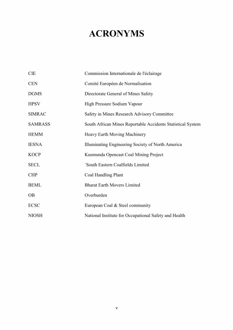
ACRONYMS
CIE Commission Internationale de l'éclairage
CEN Comité Européen de Normalisation
DGMS Directorate General of Mines Safety
HPSV High Pressure Sodium Vapour
SIMRAC Safety in Mines Research Advisory Committee
SAMRASS South African Mines Reportable Accidents Statistical System
HEMM Heavy Earth Moving Machinery
IESNA Illuminating Engineering Society of North America
KOCP Kusmunda Opencast Coal Mining Project
SECL `South Eastern Coalfields Limited
CHP Coal Handling Plant
BEML Bharat Earth Movers Limited
OB Overburden
ECSC European Coal & Steel community
NIOSH National Institute for Occupational Safety and Health
vi
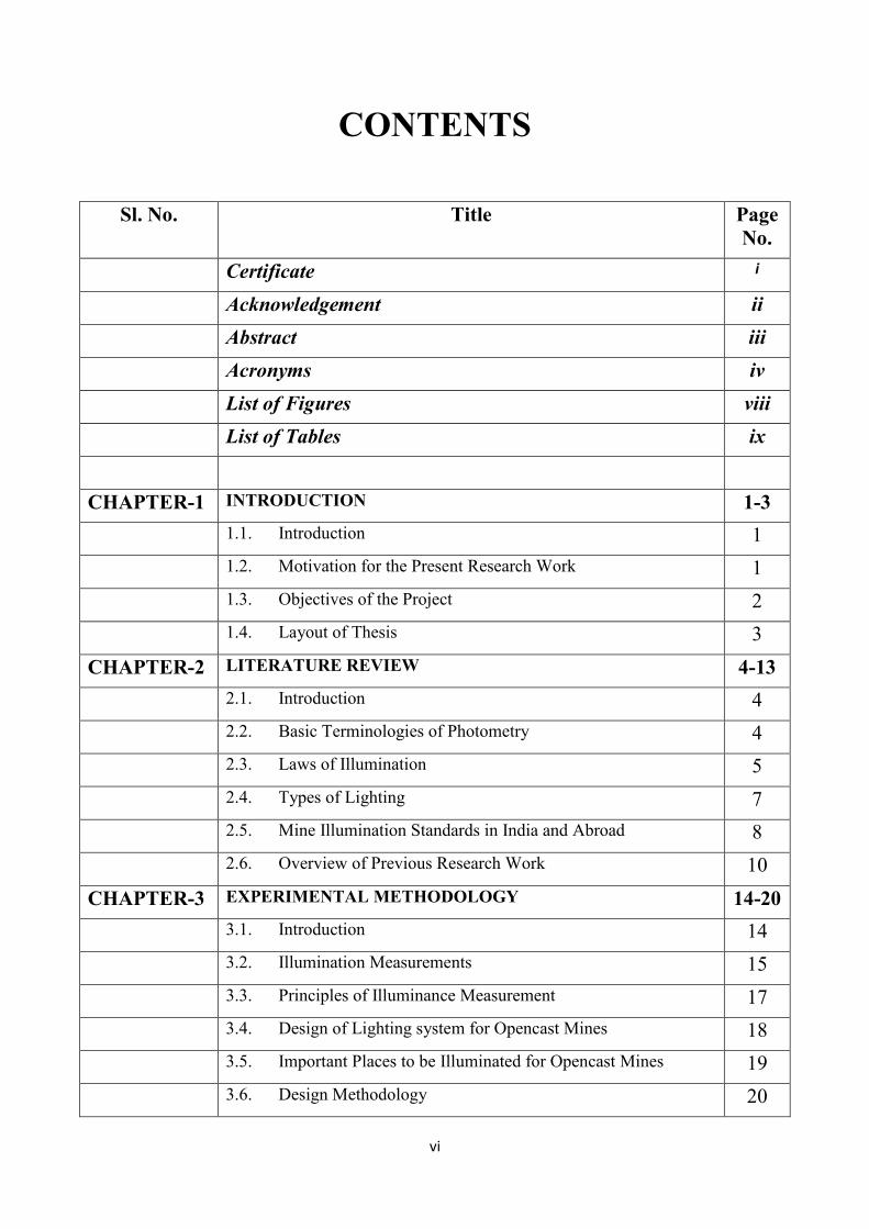
CONTENTS
Sl. No. Title Page
No.
Certificate i
Acknowledgement ii
Abstract iii
Acronyms iv
List of Figures viii
List of Tables ix
CHAPTER-1 INTRODUCTION 1-3
1.1. Introduction 1
1.2. Motivation for the Present Research Work 1
1.3. Objectives of the Project 2
1.4. Layout of Thesis 3
CHAPTER-2 LITERATURE REVIEW 4-13
2.1. Introduction 4
2.2. Basic Terminologies of Photometry 4
2.3. Laws of Illumination 5
2.4. Types of Lighting 7
2.5. Mine Illumination Standards in India and Abroad 8
2.6. Overview of Previous Research Work 10
CHAPTER-3 EXPERIMENTAL METHODOLOGY 14-20
3.1. Introduction 14
3.2. Illumination Measurements 15
3.3. Principles of Illuminance Measurement 17
3.4. Design of Lighting system for Opencast Mines 18
3.5. Important Places to be Illuminated for Opencast Mines 19
3.6. Design Methodology 20
vii
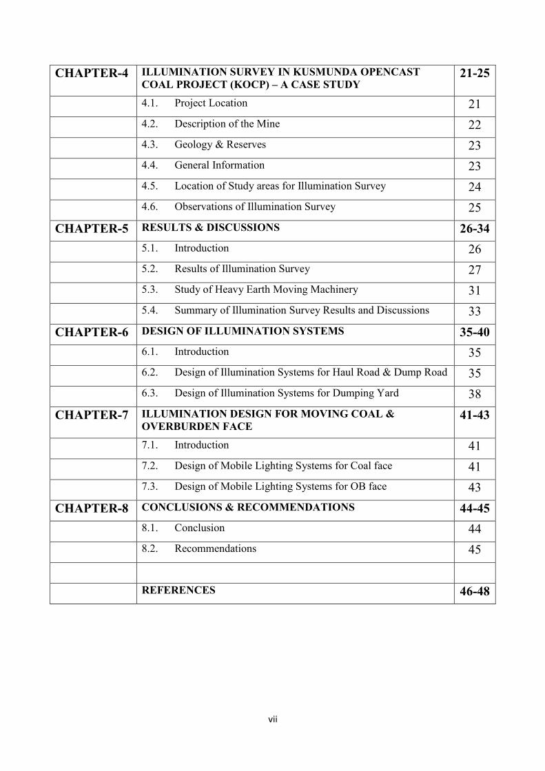
CHAPTER-4 ILLUMINATION SURVEY IN KUSMUNDA OPENCAST
COAL PROJECT (KOCP) – A CASE STUDY 21-25
4.1. Project Location 21
4.2. Description of the Mine 22
4.3. Geology & Reserves 23
4.4. General Information 23
4.5. Location of Study areas for Illumination Survey 24
4.6. Observations of Illumination Survey 25
CHAPTER-5 RESULTS & DISCUSSIONS 26-34
5.1. Introduction 26
5.2. Results of Illumination Survey 27
5.3. Study of Heavy Earth Moving Machinery 31
5.4. Summary of Illumination Survey Results and Discussions 33
CHAPTER-6 DESIGN OF ILLUMINATION SYSTEMS 35-40
6.1. Introduction 35
6.2. Design of Illumination Systems for Haul Road & Dump Road 35
6.3. Design of Illumination Systems for Dumping Yard 38
CHAPTER-7 ILLUMINATION DESIGN FOR MOVING COAL &
OVERBURDEN FACE 41-43
7.1. Introduction 41
7.2. Design of Mobile Lighting Systems for Coal face 41
7.3. Design of Mobile Lighting Systems for OB face 43
CHAPTER-8 CONCLUSIONS & RECOMMENDATIONS 44-45
8.1. Conclusion 44
8.2. Recommendations 45
REFERENCES 46-48
viii
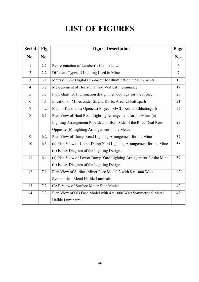
LIST OF FIGURES
Serial
No.
Fig
No.
Figure Description Page
No.
1 2.1 Representation of Lambert’s Cosine Law 6
2 2.2 Different Types of Lighting Used in Mines 7
3 3.1 Metravi 1332 Digital Lux-meter for Illumination measurements 16
4 3.2 Measurement of Horizontal and Vertical Illuminance 17
5 3.3 Flow chart for Illumination design methodology for the Project 20
6 4.1 Location of Mines under SECL, Korba Area, Chhattisgarh 21
7 4.2 Map of Kusmunda Opencast Project, SECL, Korba, Chhattisgarh 22
8 6.1 Plan View of Haul Road Lighting Arrangement for the Mine. (a)
Lighting Arrangement Provided on Both Side of the Road Dual Row
Opposite (b) Lighting Arrangement in the Median
36
9 6.2 Plan View of Dump Road Lighting Arrangement for the Mine 37
10 6.3 (a) Plan View of Upper Dump Yard Lighting Arrangement for the Mine
(b) Isolux Diagram of the Lighting Design.
38
11 6.4 (a) Plan View of Lower Dump Yard Lighting Arrangement for the Mine
(b) Isolux Diagram of the Lighting Design
39
12 7.1 Plan View of Surface Miner Face Model-3 with 8 x 1000 Watt
Symmetrical Metal Halide Luminaire
42
13 7.2 CAD View of Surface Miner Face Model 42
14 7.3 Plan View of OB Face Model with 4 x 1000 Watt Symmetrical Metal
Halide Luminaire.
43
ix
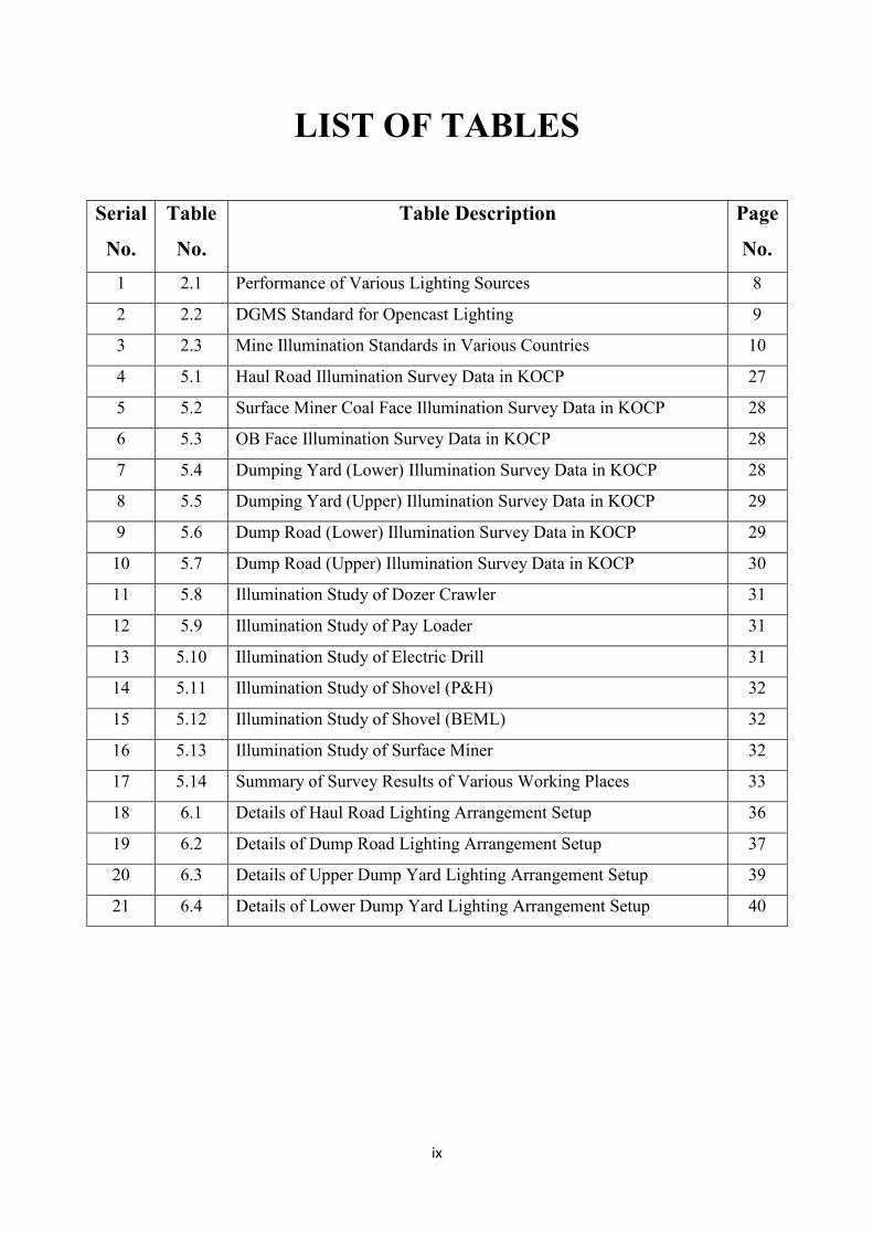
LIST OF TABLES
Serial
No.
Table
No.
Table Description Page
No.
1 2.1 Performance of Various Lighting Sources 8
2 2.2 DGMS Standard for Opencast Lighting 9
3 2.3 Mine Illumination Standards in Various Countries 10
4 5.1 Haul Road Illumination Survey Data in KOCP 27
5 5.2 Surface Miner Coal Face Illumination Survey Data in KOCP 28
6 5.3 OB Face Illumination Survey Data in KOCP 28
7 5.4 Dumping Yard (Lower) Illumination Survey Data in KOCP 28
8 5.5 Dumping Yard (Upper) Illumination Survey Data in KOCP 29
9 5.6 Dump Road (Lower) Illumination Survey Data in KOCP 29
10 5.7 Dump Road (Upper) Illumination Survey Data in KOCP 30
11 5.8 Illumination Study of Dozer Crawler 31
12 5.9 Illumination Study of Pay Loader 31
13 5.10 Illumination Study of Electric Drill 31
14 5.11 Illumination Study of Shovel (P&H) 32
15 5.12 Illumination Study of Shovel (BEML) 32
16 5.13 Illumination Study of Surface Miner 32
17 5.14 Summary of Survey Results of Various Working Places 33
18 6.1 Details of Haul Road Lighting Arrangement Setup 36
19 6.2 Details of Dump Road Lighting Arrangement Setup 37
20 6.3 Details of Upper Dump Yard Lighting Arrangement Setup 39
21 6.4 Details of Lower Dump Yard Lighting Arrangement Setup 40
1
CHAPTER: 1
INTRODUCTION
1.1. INTRODUCTION
Illumination is a very important factor to be understood properly and to be provided in the
mines where activities are performed in the night shift. The provision of adequate
illumination to ensure a safe visual working environment is particularly difficult to meet in
coal mining. In general, vision is influenced by three main lighting design parameters:
illuminance level of the surface, uniformity of light distribution and glare from sources.
Luminous intensity of light source takes care of illuminance levels on visual tasks, whereas
uniform distribution pattern of light depends on the technological aspects like luminaire
layout, aiming angle and positioning of the light sources.
1.2. MOTIVATION FOR THE PRESENT RESEARCH WORK
In opencast coal mining where the activities are also performed in night shifts because of
mass production requirements, requires effective illumination design in workplaces. The dark
surrounding and low surface reflectance significantly affects productivity and safety of
miners. Due to this reason it is very difficult to maintain the lighting standards specified by
various regulatory bodies. Hence, a scientific approach is required to achieve better
illumination standards in mines in particular. An effective lighting installation is one, which
has been designed and installed so that individual may work with safety and efficiency, and
with reasonable comfort. The lighting design process begins by carefully determining these
needs and then practical, technical, and economic factors are considered in establishing an
appropriate illumination system design. The lighting design process identifies the visual
needs of coal miners and indicates in general terms what can be done to accommodate the
needs. The environmental factors that affect the visibility of the surroundings are low surface
2
reflectance, suspended dust, and water vapors that cause backscattering and reduce apparent
illuminance. Hence, a suitable lighting design must account for these factors in addition to
luminaire design aspects.
1.3. OBJECTIVES OF THE PROJECT
The primary objectives of the project was to design an effective lighting system at different
places of work to ensure safe visual working environment in an opencast coal mining project
with due compliance of statutory standards. The research investigations were carried out with
the following objectives:
To conduct illumination survey and check the adequacy of lighting at vis-à-vis
Directorate General of Mines Safety(DGMS) /International standards at:
Different places of work in the mine
Different Heavy Earth Moving Machineries(HEMMs)
Design of appropriate illumination systems based on illumination requirement for:
Haul road
Overburden(OB) transport road
Dump yard
Moving Coal & OB faces.
3
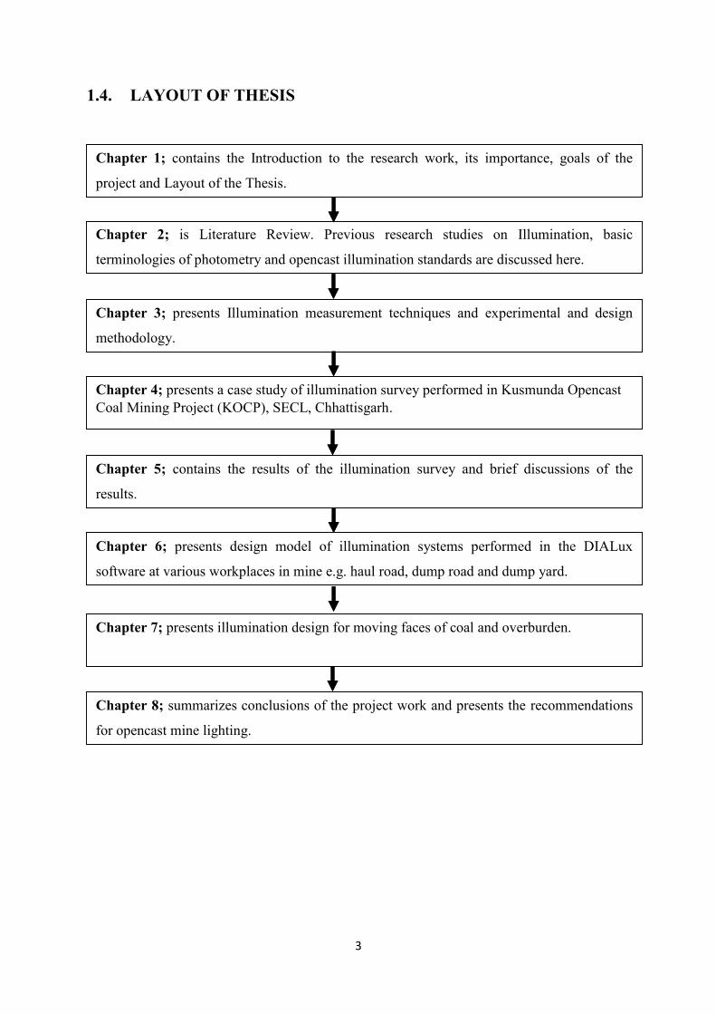
1.4. LAYOUT OF THESIS
Chapter 1; contains the Introduction to the research work, its importance, goals of the
project and Layout of the Thesis.
Chapter 2; is Literature Review. Previous research studies on Illumination, basic
terminologies of photometry and opencast illumination standards are discussed here.
Chapter 3; presents Illumination measurement techniques and experimental and design
methodology.
Chapter 4; presents a case study of illumination survey performed in Kusmunda Opencast
Coal Mining Project (KOCP), SECL, Chhattisgarh.
Chapter 5; contains the results of the illumination survey and brief discussions of the
results.
Chapter 6; presents design model of illumination systems performed in the DIALux
software at various workplaces in mine e.g. haul road, dump road and dump yard.
Chapter 7; presents illumination design for moving faces of coal and overburden.
Chapter 8; summarizes conclusions of the project work and presents the recommendations
for opencast mine lighting.
4
CHAPTER: 2
LITERATURE REVIEW
2.1. INTRODUCTION
Good lighting is very much required for safety and production. Physiological suitability of a
person to his working environment is very much important from safety point of view. Certain
evidences shows that 88% of the mine accidents are attributed to unsafe acts and only 2% are
attributed to unforeseen circumstances [10]. It is realized that if a task is performed in poor
lighting for long time sign of strain appear in the individual and if not checked, can lead to
physical illness. The increased mechanization demands that the lighting should be adequate
and suitable in order to reduce accidents. Good lighting encourages visual performance,
improves quality of work, reduces the frequency of errors and prevents fatigue, and improves
visual communication with the working environment.
2.2. BASIC TERMINOLOGIES OF PHOTOMETRY
The different terminologies used in illumination are discussed below:
2.2.1. Luminous Flux
Luminous flux describes the total amount of light emitted by a light source. The amount of
light emitted by a light source is the luminous flux Φ and its unit is lumen (lm) [1].
2.2.2. Luminous Efficacy
Luminous efficacy is defined as the luminous flux of a lamp in relation to its power
consumption and is therefore expressed in lumen per watt (lm/W). Luminous efficacy varies
from light source to light source [1].
5
2.2.3. Luminous Intensity
An ideal point-source radiates luminous flux uniformly into the space in all directions. This
result partly from the design of the light source and partly on the way light is intentionally
directed, therefore, to have a way of presenting the spatial distribution of luminous flux, i.e.
the luminous intensity distribution of the light source. The unit for measuring luminous
intensity is candela (cd) [2].
2.2.4. Illuminance
Illuminance is the amount of luminous flux from a light source falling on a given area and
can be determined from the luminous intensity of the light source. Illuminance decreases with
the square of the distance from the light source (inverse square law). The unit for
measurement is lux [2].
2.2.5. Luminance
Luminance is defined as the ratio of luminous intensity of a surface (cd) to the projected area
of the surface (m2) [2].
2.3. LAWS OF ILLUMINATION
The cosine law and the inverse square law are two very useful lighting laws and discussed
below:
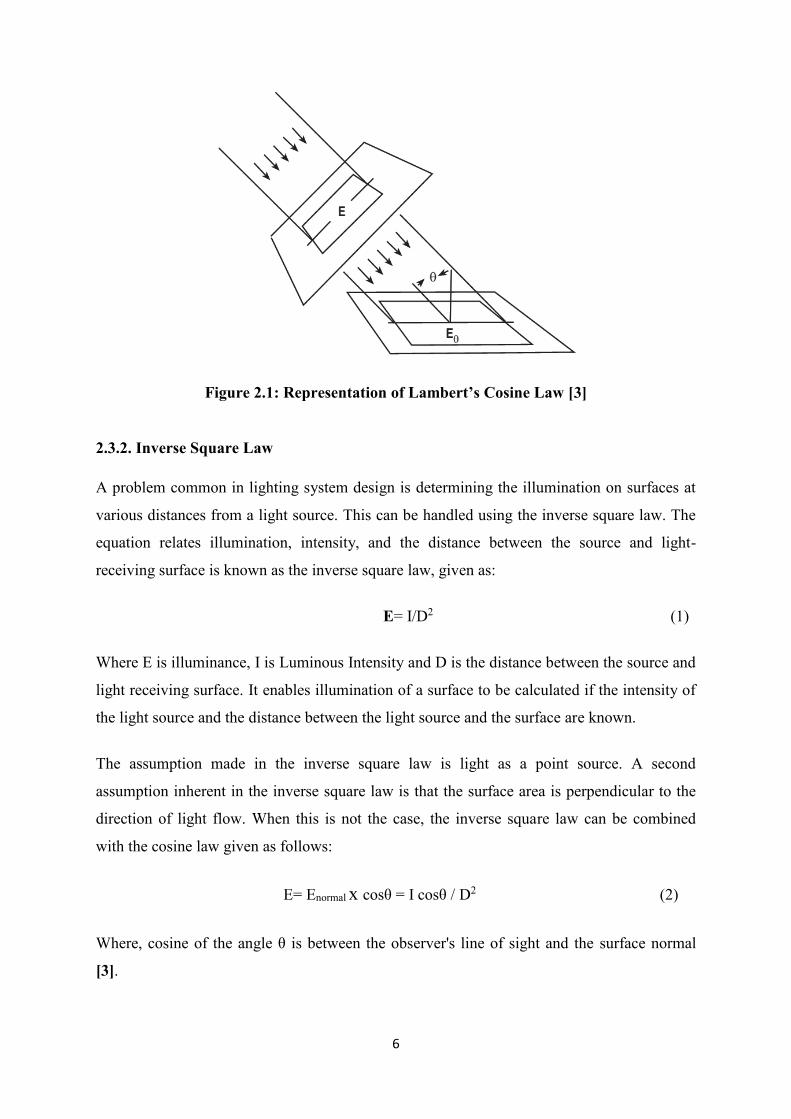
2.3.1. Lambert’s Cosine Law
Lambert's cosine law states that the luminous intensity observed from an ideal diffused
reflecting surface is directly proportional to the cosine of the angle θ between the observer's
line of sight and the surface normal. The representation of Lamberts Cosine Law is illustrated
in the Fig. 2.1 [3].
6
Figure 2.1: Representation of Lambert’s Cosine Law [3]
2.3.2. Inverse Square Law
A problem common in lighting system design is determining the illumination on surfaces at
various distances from a light source. This can be handled using the inverse square law. The
equation relates illumination, intensity, and the distance between the source and light-
receiving surface is known as the inverse square law, given as:
E= I/D2 (1)
Where E is illuminance, I is Luminous Intensity and D is the distance between the source and
light receiving surface. It enables illumination of a surface to be calculated if the intensity of
the light source and the distance between the light source and the surface are known.
The assumption made in the inverse square law is light as a point source. A second
assumption inherent in the inverse square law is that the surface area is perpendicular to the
direction of light flow. When this is not the case, the inverse square law can be combined
with the cosine law given as follows:
E= Enormal x cosθ = I cosθ / D2 (2)
Where, cosine of the angle θ is between the observer's line of sight and the surface normal
[3].
7
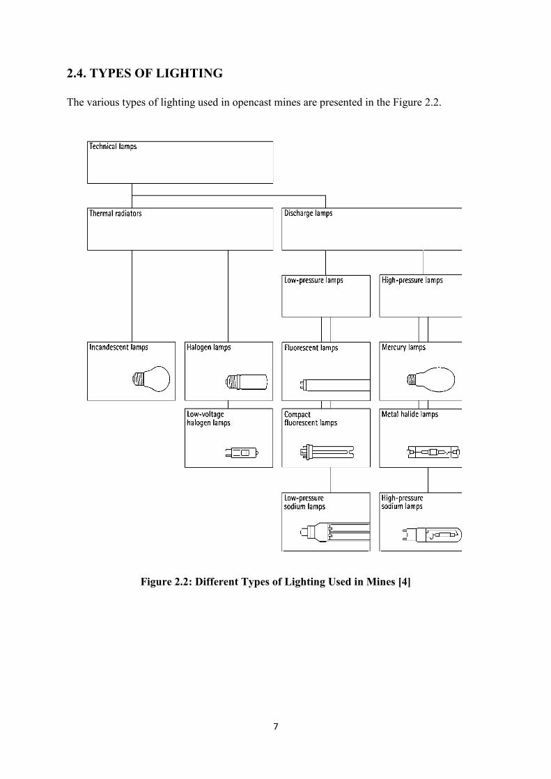
2.4. TYPES OF LIGHTING
The various types of lighting used in opencast mines are presented in the Figure 2.2.
Figure 2.2: Different Types of Lighting Used in Mines [4]
8
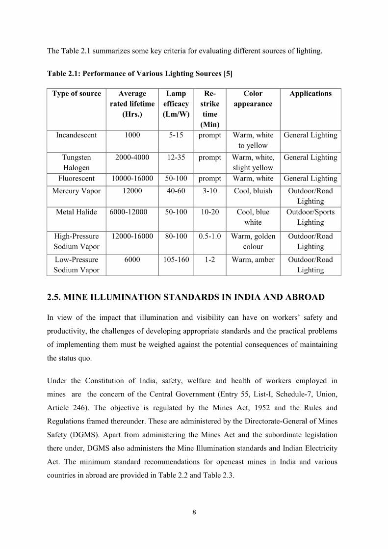
The Table 2.1 summarizes some key criteria for evaluating different sources of lighting.
Table 2.1: Performance of Various Lighting Sources [5]
Type of source Average
rated lifetime
(Hrs.)
Lamp
efficacy
(Lm/W)
Re-
strike
time
(Min)
Color
appearance
Applications
Incandescent 1000 5-15 prompt Warm, white
to yellow
General Lighting
Tungsten
Halogen
2000-4000 12-35 prompt Warm, white,
slight yellow
General Lighting
Fluorescent 10000-16000 50-100 prompt Warm, white General Lighting
Mercury Vapor 12000 40-60 3-10 Cool, bluish Outdoor/Road
Lighting
Metal Halide 6000-12000 50-100 10-20 Cool, blue
white
Outdoor/Sports
Lighting
High-Pressure
Sodium Vapor
12000-16000 80-100 0.5-1.0 Warm, golden
colour
Outdoor/Road
Lighting
Low-Pressure
Sodium Vapor
6000 105-160 1-2 Warm, amber Outdoor/Road
Lighting
2.5. MINE ILLUMINATION STANDARDS IN INDIA AND ABROAD
In view of the impact that illumination and visibility can have on workers’ safety and
productivity, the challenges of developing appropriate standards and the practical problems
of implementing them must be weighed against the potential consequences of maintaining
the status quo.
Under the Constitution of India, safety, welfare and health of workers employed in
mines are the concern of the Central Government (Entry 55, List-I, Schedule-7, Union,
Article 246). The objective is regulated by the Mines Act, 1952 and the Rules and
Regulations framed thereunder. These are administered by the Directorate-General of Mines
Safety (DGMS). Apart from administering the Mines Act and the subordinate legislation
there under, DGMS also administers the Mine Illumination standards and Indian Electricity
Act. The minimum standard recommendations for opencast mines in India and various
countries in abroad are provided in Table 2.2 and Table 2.3.
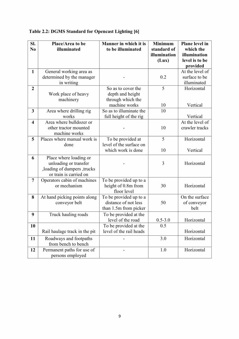
9
Table 2.2: DGMS Standard for Opencast Lighting [6]
Sl.
No
Place/Area to be
illuminated
Manner in which it is
to be illuminated
Minimum
standard of
illumination
(Lux)
Plane level in
which the
illumination
level is to be
provided
1 General working area as
determined by the manager
in writing
-
0.2
At the level of
surface to be
illuminated
2
Work place of heavy
machinery
So as to cover the
depth and height
through which the
machine works
5
10
Horizontal
Vertical
3 Area where drilling rig
works
So as to illuminate the
full height of the rig
10
Vertical
4 Area where bulldozer or
other tractor mounted
machine works
-
10
At the level of
crawler tracks
5 Places where manual work is
done
To be provided at
level of the surface on
which work is done
5
10
Horizontal
Vertical
6 Place where loading or
unloading or transfer
,loading of dumpers ,trucks
or train is carried on
-
3
Horizontal
7 Operators cabin of machines
or mechanism
To be provided up to a
height of 0.8m from
floor level
30
Horizontal
8 At hand picking points along
conveyor belt
To be provided up to a
distance of not less
than 1.5m from picker
50
On the surface
of conveyor
belt
9 Truck hauling roads To be provided at the
level of the road
0.5-3.0
Horizontal
10
Rail haulage track in the pit
To be provided at the
level of the rail heads
0.5
Horizontal
11 Roadways and footpaths
from bench to bench
- 3.0 Horizontal
12 Permanent paths for use of
persons employed
- 1.0 Horizontal
10
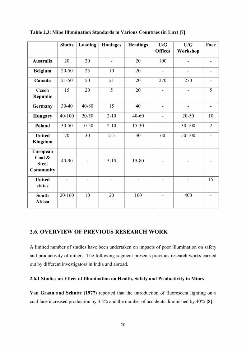
Table 2.3: Mine Illumination Standards in Various Countries (in Lux) [7]
Shafts Loading Haulages Headings U/G
Offices
U/G
Workshop
Face
Australia 20 20 - 20 100 - -
Belgium 20-50 25 10 20 - - -
Canada 21-50 50 21 20 270 270 -
Czech
Republic
15 20 5 20 - - 5
Germany 30-40 40-80 15 40 - - -
Hungary 40-100 20-50 2-10 40-60 - 20-50 10
Poland 30-50 10-50 2-10 15-30 - 30-100 2
United
Kingdom
70 30 2-5 30 60 50-100 -
European
Coal &
Steel
Community
40-90
-
5-15
15-80
-
-
-
United
states
- - - - - - 15
South
Africa
20-160 10 20 160 - 400 -
2.6. OVERVIEW OF PREVIOUS RESEARCH WORK
A limited number of studies have been undertaken on impacts of poor illumination on safety
and productivity of miners. The following segment presents previous research works carried
out by different investigators in India and abroad.
2.6.1 Studies on Effect of Illumination on Health, Safety and Productivity in Mines
Van Graan and Schutte (1977) reported that the introduction of fluorescent lighting on a
coal face increased production by 3.5% and the number of accidents diminished by 40% [8].
11
Mishra and Dixit (1978) reported in an Indian underground coal mines 35% of all
minor accidents are attributed to the poor lighting condition [9].
Trotter (1982) carried out investigations in a Hungarian mine and observed that when one
part of the mine was illuminated with special purpose fixed lighting and another solely with
cap lamps, the accident rate in the lighted portion decreased by 60%. In another mine study
in a large West Virginia coal mine in the United States, six production sections were
in operation throughout the 24-month period during which the test was carried out.
Not a single major accident was reported during this time period in the only section in which
mine lighting system was installed [10].
Franz et al. (1995) investigated some issues which supports that illumination was the only
environmental factor that could be convincingly correlated with accident occurrence.
However, another finding of that work was that the accident reports studied nearly always
focused on the immediate cause and failed to identify root causes, which could have included
unsatisfactory lighting in many instances [11].
The United States Bureau of Mines conducted a study to examine illumination levels on and
about large mobile mining machinery at surface mines. Effort focused on evaluating the task
lighting needs of the machinery operator. An intended outcome of the study was to supply
useful data and information for efforts to establish illumination standards for the surface
mining industry [12].
Odendaal (1996) investigated a number of factors as possible contributors to accidents in
four gold and four platinum mines, including illumination, and provided a number of useful
insights. It was found that approximately 74% of the occupations were solely dependent on
cap lamps for illumination during more than half of the shift and accounted for 88%– 95% of
reportable accidents during the 3 years considered. Odendaal also examined the relationship
between work rates in combination with illumination on accident occurrence and evaluated
the prevalence of judgmental errors in such events [13].
Research by the U.S. National Institute for Occupational Safety and Health (NIOSH)
indicated that light emitting diodes (LEDs) could be used to enhance safety by improving a
miner’s ability to see mining hazards [14] and reducing glare [15]. Recent National Institute
for Occupational Safety and Health research focused on the spectral characteristics of light
12
from miners’ cap lamps to improve safety. The results indicated significant gains in visual
performance that could reduce pinning/striking accidents [16] slip/trip/fall accidents and
glare-induced accidents [17].
Tyson (1999) reported that lighting was a contributing factor in only 2% of opencast fatalities
and also observed that in 13 separate underground fatalities between 1976 and 1985 poor
lighting resulted in accidents [18].
2.6.2 Experimental Studies on Mine Illumination Survey
Mayton (1991) investigated different surface mining operations in various regions of the
United States using visual task evaluation, a method used by the CIE and the IES. Visibility
and illumination data were collected during site visits to surface mines and quarries in 15
metal–nonmetal mines and seven coal mines. Visual tasks were identified for equipment
operators on 57 types of surface mining and quarry equipment. Visibility and illumination
were measured for 159 tasks. Measurements of visibility area were made with the Blackwell
model 5 visual task evaluation. Existing illuminance for each task was determined with a
Minolta luminance meter and a reflectance standard RS-1. He concluded that the illumination
level varied from mine to mine for the same tasks and equipment and also suggested that the
visibility and illumination on dozers and loaders can be improved by assuring the proper
aiming of luminaires and replacing existing lamps with those of higher intensity [19].
Karmakar et al. (2005) developed a computer model for design and economic analysis of
lighting system in an opencast mine. The study revealed that mounting height was very
important in order to achieve all the required lighting standards. With low-wattage high
pressure mercury vapor lamps, the pole height was kept lowered to achieve the necessary
lighting standards. HPSV lamps possessed better Isolux contour for haul road illumination.
For the light sources studied in the work, 100W HPSV lamps at 12m height gave the
optimum design (9737 kWh annual energy consumption), whereas at 16m height the
minimum energy consumption was 7534 kWh for 150W lamps [20].
Aruna and Jaralikar (2012) designed a lighting system for both mineral and overburden
benches based on the minimum acceptable reflected light and the reflected uniformity ratio.
For comparison of various types of lighting systems, a stretch of a 1.0 km long haul road was
considered. The design was attempted with five different types of luminaires. Lamp mounting
13
heights were varied at five steps, namely, 8, 10, 12, 14, and 16m. Design under wet
conditions incurred an excess cost of 9.4% for mineral bench haul road and 50% for
overburden bench haul roads. Design under wet surface conditions ensured the minimum
light level even under worst condition of surface reflectivity with marginal increase in cost
[21].
Das and Roul (2005) performed an illumination study in a highly mechanized opencast
bauxite mine of National Aluminium Company Ltd (NALCO) in which design was provided
for 9m lighting tower and 18m telescopic tilt-able tower. Also, design of haul road and
auxiliary haul road illumination system was performed [22].
Pal et al. (2012) proposed design system of haul roads lighting for an opencast coal mine
using green energy. A prototype board was also constructed and it showed fairly constant
lumen output over varying input voltages [23].
14
CHAPTER: 3
EXPERIMENTAL METHODOLOGY
3.1. INTRODUCTION
For simple lighting installations, hand calculations based on tabular data are used to provide
an acceptable lighting design. More critical or optimized designs now routinely use
mathematical modeling on a computer. Based on the positions and mounting heights of the
fixtures and their photometric characteristics, the proposed lighting layout can be checked for
uniformity and quantity of illumination (illuminance). For larger projects lighting design
software can be used. Each fixture has its location entered, and then the design parameters
and working environment can be entered. The computer program will then produce a set of
contour charts overlaid on the project floor plan, showing the light level to be expected at the
working height. More advanced programs can include the effect of light from luminaires,
allowing further optimization of the operating cost of the lighting installation. The amount of
artificial light received in an internal space can typically be analyzed by undertaking
a daylight factor calculation [24].
Computer modeling of outdoor flood lighting usually proceeds directly from photometric
data. The total luminous energy of a lamp is divided into small solid angular regions. Each
region is extended to the surface which is to be lit and the area calculated, giving the light
power per unit of area. Where multiple lamps are used to illuminate the same area, net
contribution is obtained. Again the tabulated light levels (in lux or foot-candles) can be
presented as contour lines of constant lighting value, overlaid on the project plan drawing.
Hand calculations might only be required at a few points, but computer calculations allow a
better estimate of the uniformity and lighting level [24].
15
3.2. ILLUMINATION MEASUREMENTS
Instruments are required to evaluate lighting systems and components. The field of light
measurement is called photometry, and the instruments used to measure lighting are called
photometers. Many types of photometers are available to measure light energy and related
quantities, including illuminance, luminance, luminous intensity, luminous flux, contrast,
color and visibility. The photometer is one of the most important tools for illumination
measurement and evaluation of efficacy of illumination system.
Specific uses for mine illumination system measurements are-
Verification of compliance with illumination and luminance specifications in the
regulations;
Evaluation of illumination system design options;
Checking light distribution;
Photometric measurements in mines are of three types: illuminance measurement, Luminance
measurement, and reflectance measurement.
3.2.1. Illuminance Measurement
This process measures the incident light (in lux) received by a surface. Most countries specify
their lighting standard in lux, so this method is most widely used in mine surveys. Three
different techniques can be used in mine illumination surveys:
Direct planar measurement
Separate measurements for direct and diffused light
Maximum reading method [25]
3.2.2. Luminance Measurement
The photometer is aimed at the surface to be measured. Luminance measurements state that
the photometer shall be held approximately perpendicular to the surface being measured.
They also require that the sensing element be at a sufficient distance from the surface to allow
the light sensing element to receive reflected light from a field not less than 3 ft2 or more than
5 ft2 [25].
16
3.2.3 Reflectance Measurement
Design of mine illumination requires a thorough knowledge of reflectance of the rock surface
in the mine. Four different methods are employed. These are
Incident–reflected light comparison
Standard chips comparison
Reflectance standard comparison
Sphere reflectometry [25].
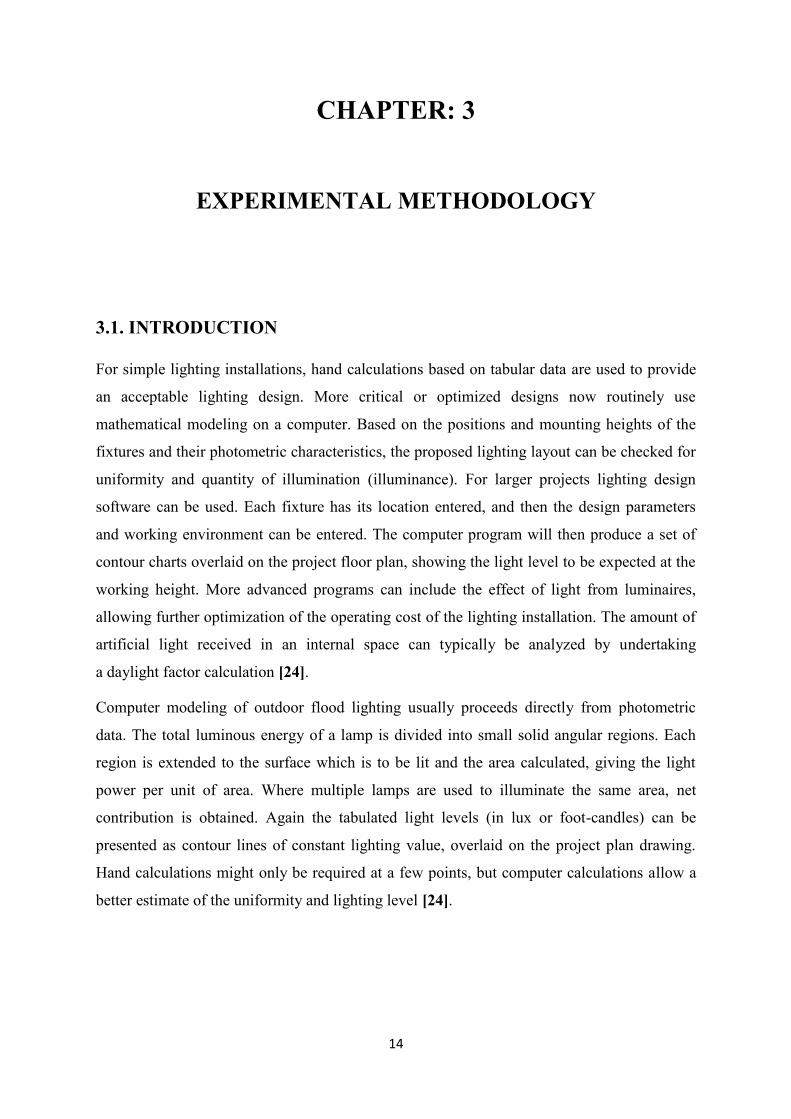
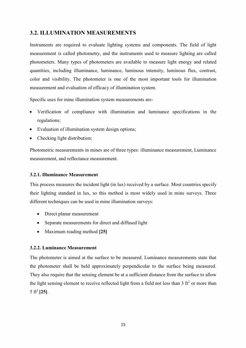
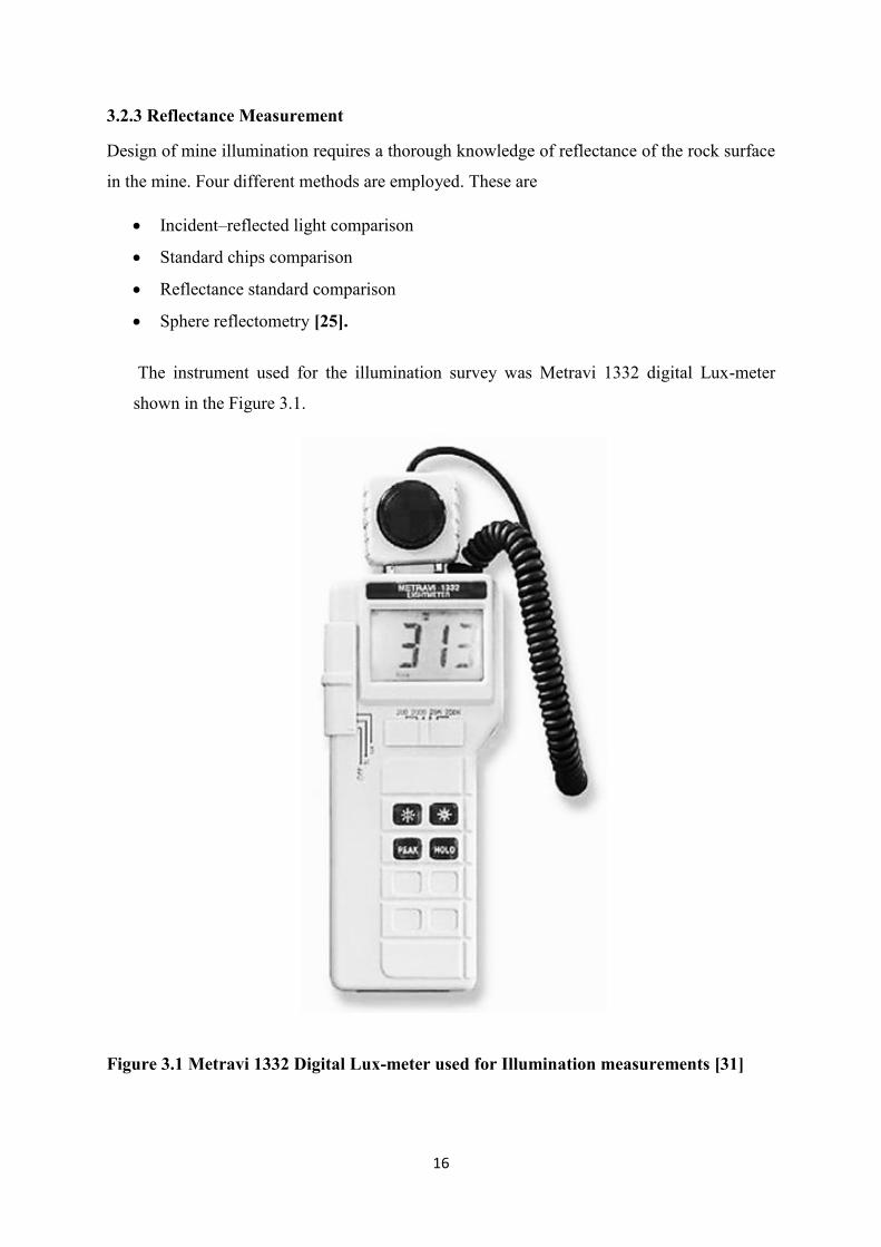
The instrument used for the illumination survey was Metravi 1332 digital Lux-meter
shown in the Figure 3.1.
Figure 3.1 Metravi 1332 Digital Lux-meter used for Illumination measurements [31]
17
3.3. PRINCIPLES OF ILLUMINANCE MEASUREMENT
In mine lighting, illuminance measurements are typically taken for the following purposes:
To determine the incident luminous energy (lux) on a surface.
To determine the light output characteristics of a luminaire.
To determine if illuminance levels are sufficient to qualify the illumination system for
DGMS approval.
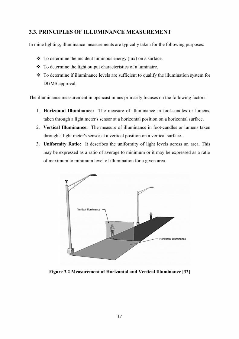
The illuminance measurement in opencast mines primarily focuses on the following factors:
1. Horizontal Illuminance: The measure of illuminance in foot-candles or lumens,
taken through a light meter's sensor at a horizontal position on a horizontal surface.
2. Vertical Illuminance: The measure of illuminance in foot-candles or lumens taken
through a light meter's sensor at a vertical position on a vertical surface.
3. Uniformity Ratio: It describes the uniformity of light levels across an area. This
may be expressed as a ratio of average to minimum or it may be expressed as a ratio
of maximum to minimum level of illumination for a given area.
Figure 3.2 Measurement of Horizontal and Vertical Illuminance [32]
18
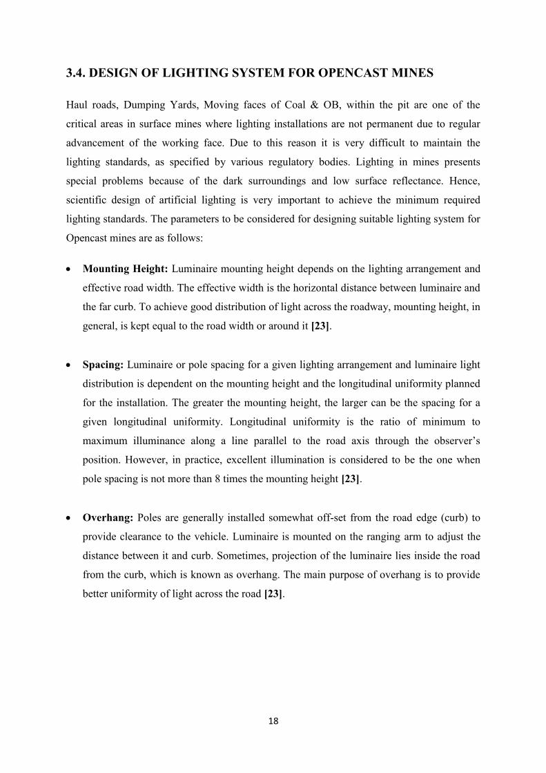
3.4. DESIGN OF LIGHTING SYSTEM FOR OPENCAST MINES
Haul roads, Dumping Yards, Moving faces of Coal & OB, within the pit are one of the
critical areas in surface mines where lighting installations are not permanent due to regular
advancement of the working face. Due to this reason it is very difficult to maintain the
lighting standards, as specified by various regulatory bodies. Lighting in mines presents
special problems because of the dark surroundings and low surface reflectance. Hence,
scientific design of artificial lighting is very important to achieve the minimum required
lighting standards. The parameters to be considered for designing suitable lighting system for
Opencast mines are as follows:
Mounting Height: Luminaire mounting height depends on the lighting arrangement and
effective road width. The effective width is the horizontal distance between luminaire and
the far curb. To achieve good distribution of light across the roadway, mounting height, in
general, is kept equal to the road width or around it [23].
Spacing: Luminaire or pole spacing for a given lighting arrangement and luminaire light
distribution is dependent on the mounting height and the longitudinal uniformity planned
for the installation. The greater the mounting height, the larger can be the spacing for a
given longitudinal uniformity. Longitudinal uniformity is the ratio of minimum to
maximum illuminance along a line parallel to the road axis through the observer’s
position. However, in practice, excellent illumination is considered to be the one when
pole spacing is not more than 8 times the mounting height [23].
Overhang: Poles are generally installed somewhat off-set from the road edge (curb) to
provide clearance to the vehicle. Luminaire is mounted on the ranging arm to adjust the
distance between it and curb. Sometimes, projection of the luminaire lies inside the road
from the curb, which is known as overhang. The main purpose of overhang is to provide
better uniformity of light across the road [23].
19
Inclination: Inclining or tilting the luminaires up from the horizontal is done to increase
light coverage across the road width at a given mounting height. It is recommended that
the angle of tilt with respect to the normal height of mounting be limited to an absolute
maximum of 10°, a top limit of 5° being preferable. In general the angle varies from 10°
to 15° [23].
3.5. IMPORTANT PLACES TO BE ILLUMINATED FOR OPENCAST
MINES
At the Working faces of Ore/Overburden to facilitate digging and loading operation for
positioning buckets during loading and unloading.
Material to be loaded and filling level in the bucket or bowl.
Illumination of haul roads.
Spotting dumpers for loading and unloading at the dump yard, stack-yards etc.
Viewing the edge and dump of the general area.
Inside the Cabins of the machineries and along walkways.
Below the shovels, under the carriage to identify any leakage for handling of trailing
cables during relocation maneuvers.
Over the dock of shovels and draglines for routine maintenance and inspection.
In case of conveyor haulage system lighting is mainly needed for inspection and
maintenance.
At crusher site, bunkers, vibrators, washers and loading point.
At maintenance shop, general repairing workshop, auto electrical shop and other places as
suggested in DGMS standards.
20
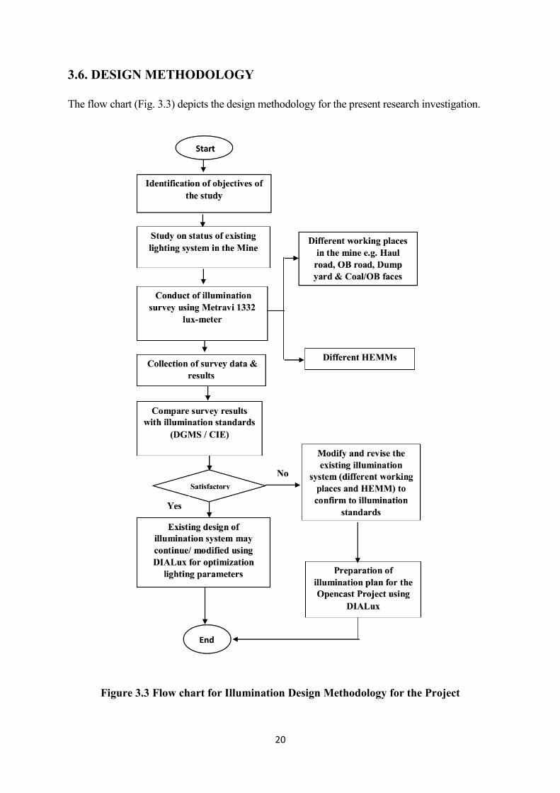
3.6. DESIGN METHODOLOGY
The flow chart (Fig. 3.3) depicts the design methodology for the present research investigation.
Figure 3.3 Flow chart for Illumination Design Methodology for the Project
21
CHAPTER: 4
ILLUMINATION SURVEY IN KUSMUNDA
OPENCAST COAL PROJECT (KOCP) - A CASE
STUDY
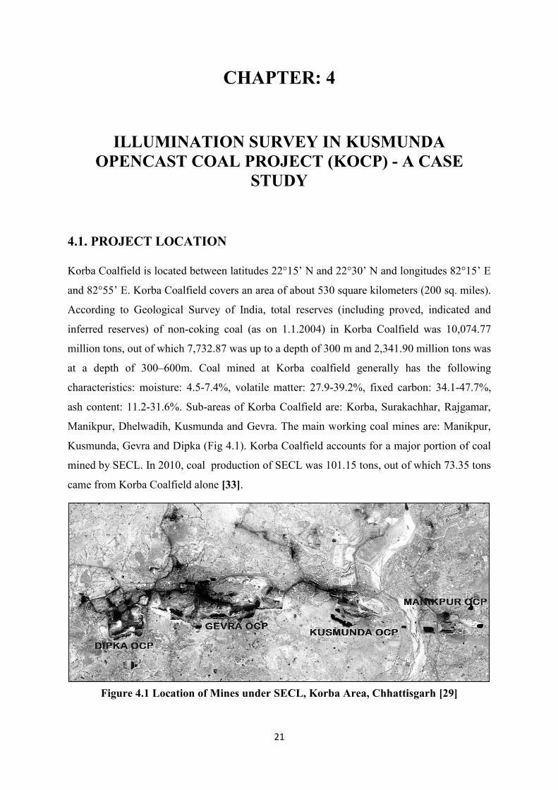
4.1. PROJECT LOCATION
Korba Coalfield is located between latitudes 22°15’ N and 22°30’ N and longitudes 82°15’ E
and 82°55’ E. Korba Coalfield covers an area of about 530 square kilometers (200 sq. miles).
According to Geological Survey of India, total reserves (including proved, indicated and
inferred reserves) of non-coking coal (as on 1.1.2004) in Korba Coalfield was 10,074.77
million tons, out of which 7,732.87 was up to a depth of 300 m and 2,341.90 million tons was
at a depth of 300–600m. Coal mined at Korba coalfield generally has the following
characteristics: moisture: 4.5-7.4%, volatile matter: 27.9-39.2%, fixed carbon: 34.1-47.7%,
ash content: 11.2-31.6%. Sub-areas of Korba Coalfield are: Korba, Surakachhar, Rajgamar,
Manikpur, Dhelwadih, Kusmunda and Gevra. The main working coal mines are: Manikpur,
Kusmunda, Gevra and Dipka (Fig 4.1). Korba Coalfield accounts for a major portion of coal
mined by SECL. In 2010, coal production of SECL was 101.15 tons, out of which 73.35 tons
came from Korba Coalfield alone [33].
Figure 4.1 Location of Mines under SECL, Korba Area, Chhattisgarh [29]
22
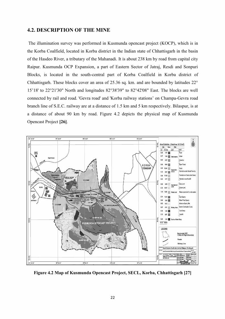
4.2. DESCRIPTION OF THE MINE
The illumination survey was performed in Kusmunda opencast project (KOCP), which is in
the Korba Coalfield, located in Korba district in the Indian state of Chhattisgarh in the basin
of the Hasdeo River, a tributary of the Mahanadi. It is about 238 km by road from capital city
Raipur. Kusmunda OCP Expansion, a part of Eastern Sector of Jatraj, Resdi and Sonpuri
Blocks, is located in the south-central part of Korba Coalfield in Korba district of
Chhattisgarh. These blocks cover an area of 25.36 sq. km. and are bounded by latitudes 22°
15’18' to 22°21'30" North and longitudes 82°38'39" to 82°42'08" East. The blocks are well
connected by rail and road. 'Gevra road' and 'Korba railway stations’ on Champa-Gevra road
branch line of S.E.C. railway are at a distance of 1.5 km and 5 km respectively. Bilaspur, is at
a distance of about 90 km by road. Figure 4.2 depicts the physical map of Kusmunda
Opencast Project [26].
Figure 4.2 Map of Kusmunda Opencast Project, SECL, Korba, Chhattisgarh [27]
23
4.3. GEOLOGY & RESERVES
A Mining Block covering an area of 9.67 sq.-km has been considered in the Kusmunda
Opencast Expansion Project (15MTY). The boundaries of the mining blocks are given below:
-North: An arbitrary line passing north of borehole CMKK-192, 125 and NCKK-48, 81 and
56. South: An arbitrary line passing south of boreholes CMKL-101, 117, 123 CKKS-17,
CMKR-53, 70, 10, 21 & CMKS-14 (corresponding to a maximum depth of 240m on lower
Kusmunda Seam). East: West Bank Canal of Hasdeo River. West: An arbitrary line west of
boreholes NCKK-15, 22, 21, 25, CMKL- 55, 56, 68, 114 and 184, RL 295.0 [26].
4.4. GENERAL INFORMATION ABOUT KOCP [26]
Name of the Mine: Kusmunda Opencast Project
Total Area: 2536.24 Hectare.
Total Mineable Coal Reserves: 430.03 Million tons (as on 01.04.12)
Total Overburden Reserves: 707.66 Million cubic meters (as on 01.04.12)
Life of the Mine: 29 years @ 15 MT/Year
Name of Seams: Upper Kusmunda and Lower Kusmunda
Quality of Seams: Grade-F
Overall Quality of the Coal: G-11
Average Stripping Ratio: 1.42 cubic meter/ton
Thickness of the Seam: Upper Kusmunda 9.5m to 35.73m
Lower Kusmunda Top Split 30.02m to 43.60m
Composite Seam 50.85m to 60.22m.
Lower Kusmunda Bottom Split 5.18m to 16.65m
Dip of Seam: 4º to 10º.
Extent of the Mine: 2.0 km along the Strike.
1.5 km along the Dip.
110 to 150 m by Depth.
24
4.5. LOCATION OF STUDY AREAS FOR ILLUMINATION SURVEY
The details of the study areas of the mine under study are given below:
4.5.1. Haul Road
Haul roads are maintained keeping width three times of the largest plying dumper/trucks, and
gradient is kept smoother than 1 in 16. At corners and curves, visibility to drivers is
maintained at least 30m. At slopes separate lane is provided for up and down traffic. The
length of the mine haul road is approximately 1.6km.
4.5.2. Coal Face
The method of winning coal is by pay-loader in combination with tipping trucks. Coal is
being transported up to CHP and siding by tipping trucks. Surface miners are also introduced
for winning of coal.The bench width for working in coal is 15m, for bench height of 5m.
4.5.3. Overburden (OB) Face
The method of overburden removal is by conventional shovel and dumper combination. At
present 120Te, 100Te dumpers in combination with 10 m3 & 4.6 m3 shovels. Considering the
average floor gradient of 5° to 10° the coal extraction and OB removal benches are made
parallel to the seam floor. The benches are given suitable lateral gradient towards the main
sump to avoid water logging and facilitate smooth movement of dumpers. The bench width
for working in OB is 40m for bench height of 14m. The bench slopes are maintained along
width towards height of the bench.
4.5.4. Dumping Road and Dump Yard
Stock piles and dumps are strategically located. Regular inspections of dumps are being done.
Berms in dumps are maintained as per norms. Dumpers are maintained properly with special
attention to the safety feature. 100Te and 120Te dumpers are used for dumping of
overburden. There are two dumping yards; lower dumping and upper dumping. Both
dumping roads are approximately 600m in length and width of 40m.
25
4.6. OBSERVATIONS OF ILLUMINATION SURVEY
Some observations were made during the illumination survey and are presented below:
4.6.1 Haul Road
There were luminaires tilted in left/right directions mentioned at some of the poles, due to
which lux levels were reduced. Also there were drop of operating voltage on the luminaires
which are at higher distance from the transformer location and hence reduced lux level. Some
defective luminaires are found not working, i.e. not glowing.
4.6.2 Coal Face
There were only 2, 1000 Watt HPSV lamps installed for the coal at a height of approximately
50m from the high wall side.
4.6.3 Dumping Yard
The upper dumping yard had an approximate area of 100m x 80m and there were 5 lighting
poles installed among which 4 was of 1000 Watt and the other 2x400 Watt while the lower
dumping yard had an approximate area of 120m x 60m and there were 4 lighting poles
installed among which 2 was of 1000 Watt and the others 2x400 Watt. There were not
adequate lux levels found during the survey on the dump edges as per the DGMS guidelines
but the dump edges could be identified by the heap of overburden stacked near it.
4.6.4 Dumping Road
The dump road were illuminated using 400 Watts HPSV lamps single row arrangement and
hence on the pole side lux levels were much higher and at the end along road width the lux
levels were significantly lower, which resulted in non-uniform light distribution. Some
defective luminaires are also found on the pole that is not working, i.e. not glowing.
4.6.5 OB Face
Lamps used for illumination were 1000 and 2x400 Watts HPSV. The mine was highly
mechanized with high production of OB per day, hence temporary light setup was provided.
Lux levels of the machine mounted HEMMs at OB face were enough to perform the night
operations, although peripheral lighting was low.
26
CHAPTER: 5
RESULTS AND DISCUSSION
5.1. INTRODUCTION
The illumination survey was performed in a mechanized opencast coal mine project of Coal
India Limited during June, 2013 to May, 2014. The mine had a total area of 2536.24 ha and
mineable coal reserves of 430 million tons [26]. The method of winning coal was by pay-
loader in combination with tipping trucks and surface miner. The method of overburden
removal was by conventional shovel and dumper combination. Coal was transported in to
coal handling plants as well as to nearby stacking yards. Haul roads were generally
maintained keeping the width three times of the largest plying dumpers/trucks and the
gradient of the slope was kept less than 1 in 16. At corners and curves, visibility to drivers
was maintained at least 30 m. At slopes a separate lane was provided for each direction of
traffic.
27
5.2 RESULTS OF ILLUMINATION SURVEY
The illumination survey readings in various workplaces of the mine and are represented in
Tables 5.1 to 5.7.
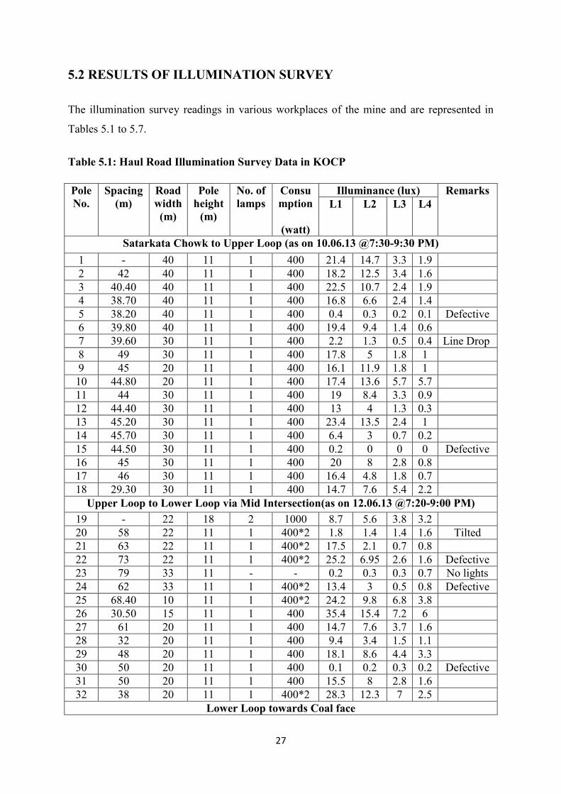
Table 5.1: Haul Road Illumination Survey Data in KOCP
Pole
No.
Spacing
(m)
Road
width
(m)
Pole
height
(m)
No. of
lamps
Consu
mption
(watt)
Illuminance (lux) Remarks
L1 L2 L3 L4
Satarkata Chowk to Upper Loop (as on 10.06.13 @7:30-9:30 PM)
1 - 40 11 1 400 21.4 14.7 3.3 1.9
2 42 40 11 1 400 18.2 12.5 3.4 1.6
3 40.40 40 11 1 400 22.5 10.7 2.4 1.9
4 38.70 40 11 1 400 16.8 6.6 2.4 1.4
5 38.20 40 11 1 400 0.4 0.3 0.2 0.1 Defective
6 39.80 40 11 1 400 19.4 9.4 1.4 0.6
7 39.60 30 11 1 400 2.2 1.3 0.5 0.4 Line Drop
8 49 30 11 1 400 17.8 5 1.8 1
9 45 20 11 1 400 16.1 11.9 1.8 1
10 44.80 20 11 1 400 17.4 13.6 5.7 5.7
11 44 30 11 1 400 19 8.4 3.3 0.9
12 44.40 30 11 1 400 13 4 1.3 0.3
13 45.20 30 11 1 400 23.4 13.5 2.4 1
14 45.70 30 11 1 400 6.4 3 0.7 0.2
15 44.50 30 11 1 400 0.2 0 0 0 Defective
16 45 30 11 1 400 20 8 2.8 0.8
17 46 30 11 1 400 16.4 4.8 1.8 0.7
18 29.30 30 11 1 400 14.7 7.6 5.4 2.2
Upper Loop to Lower Loop via Mid Intersection(as on 12.06.13 @7:20-9:00 PM)
19 - 22 18 2 1000 8.7 5.6 3.8 3.2
20 58 22 11 1 400*2 1.8 1.4 1.4 1.6 Tilted
21 63 22 11 1 400*2 17.5 2.1 0.7 0.8
22 73 22 11 1 400*2 25.2 6.95 2.6 1.6 Defective
23 79 33 11 - - 0.2 0.3 0.3 0.7 No lights
24 62 33 11 1 400*2 13.4 3 0.5 0.8 Defective
25 68.40 10 11 1 400*2 24.2 9.8 6.8 3.8
26 30.50 15 11 1 400 35.4 15.4 7.2 6
27 61 20 11 1 400 14.7 7.6 3.7 1.6
28 32 20 11 1 400 9.4 3.4 1.5 1.1
29 48 20 11 1 400 18.1 8.6 4.4 3.3
30 50 20 11 1 400 0.1 0.2 0.3 0.2 Defective
31 50 20 11 1 400 15.5 8 2.8 1.6
32 38 20 11 1 400*2 28.3 12.3 7 2.5
Lower Loop towards Coal face
28
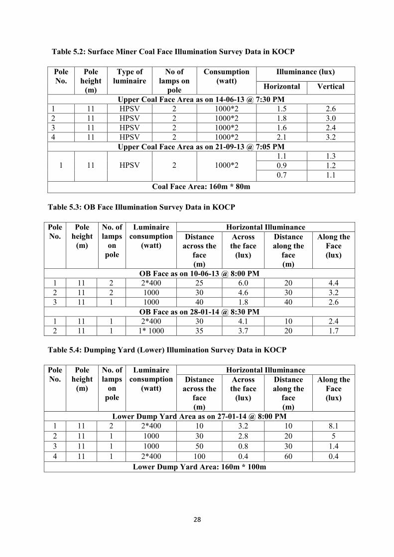
Table 5.2: Surface Miner Coal Face Illumination Survey Data in KOCP
Pole
No.
Pole
height
(m)
Type of
luminaire
No of
lamps on
pole
Consumption
(watt)
Illuminance (lux)
Horizontal Vertical
Upper Coal Face Area as on 14-06-13 @ 7:30 PM
1 11 HPSV 2 1000*2 1.5 2.6
2 11 HPSV 2 1000*2 1.8 3.0
3 11 HPSV 2 1000*2 1.6 2.4
4 11 HPSV 2 1000*2 2.1 3.2
Upper Coal Face Area as on 21-09-13 @ 7:05 PM
1
11
HPSV
2
1000*2
1.1 1.3
0.9 1.2
0.7 1.1
Coal Face Area: 160m * 80m
Table 5.3: OB Face Illumination Survey Data in KOCP
Pole
No.
Pole
height
(m)
No. of
lamps
on
pole
Luminaire
consumption
(watt)
Horizontal Illuminance
Distance
across the
face
(m)
Across
the face
(lux)
Distance
along the
face
(m)
Along the
Face
(lux)
OB Face as on 10-06-13 @ 8:00 PM
1 11 2 2*400 25 6.0 20 4.4
2 11 2 1000 30 4.6 30 3.2
3 11 1 1000 40 1.8 40 2.6
OB Face as on 28-01-14 @ 8:30 PM
1 11 1 2*400 30 4.1 10 2.4
2 11 1 1* 1000 35 3.7 20 1.7
Table 5.4: Dumping Yard (Lower) Illumination Survey Data in KOCP
Pole
No.
Pole
height
(m)
No. of
lamps
on
pole
Luminaire
consumption
(watt)
Horizontal Illuminance
Distance
across the
face
(m)
Across
the face
(lux)
Distance
along the
face
(m)
Along the
Face
(lux)
Lower Dump Yard Area as on 27-01-14 @ 8:00 PM
1 11 2 2*400 10 3.2 10 8.1
2 11 1 1000 30 2.8 20 5
3 11 1 1000 50 0.8 30 1.4
4 11 1 2*400 100 0.4 60 0.4
Lower Dump Yard Area: 160m * 100m
29
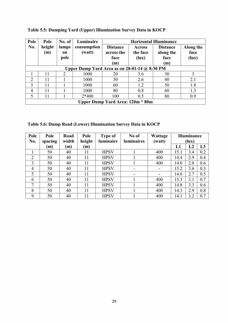
Table 5.5: Dumping Yard (Upper) Illumination Survey Data in KOCP
Pole
No.
Pole
height
(m)
No. of
lamps
on
pole
Luminaire
consumption
(watt)
Horizontal Illuminance
Distance
across the
face
(m)
Across
the face
(lux)
Distance
along the
face
(m)
Along the
face
(lux)
Upper Dump Yard Area as on 28-01-14 @ 8:30 PM
1 11 2 1000 20 3.6 30 3
2 11 1 1000 30 2.6 40 2.1
3 11 1 1000 60 1.2 50 1.8
4 11 1 1000 80 0.8 60 1.3
5 11 1 2*400 100 0.5 80 0.9
Upper Dump Yard Area: 120m * 80m
Table 5.6: Dump Road (Lower) Illumination Survey Data in KOCP
Pole
No.
Pole
spacing
(m)
Road
width
(m)
Pole
height
(m)
Type of
luminaire
No of
luminaires
Wattage
(watt)
Illuminance
(lux)
L1 L2 L3
1 50 40 11 HPSV 1 400 15.1 3.4 0.2
2 50 40 11 HPSV 1 400 14.4 2.9 0.4
3 50 40 11 HPSV 1 400 14.0 2.8 0.6
4 50 40 11 HPSV - - 15.2 3.6 0.3
5 50 40 11 HPSV - - 14.6 2.7 0.5
6 50 40 11 HPSV 1 400 15.3 3.1 0.7
7 50 40 11 HPSV 1 400 14.8 3.3 0.6
8 50 40 11 HPSV 1 400 14.3 2.9 0.8
9 50 40 11 HPSV 1 400 14.1 3.2 0.7
30
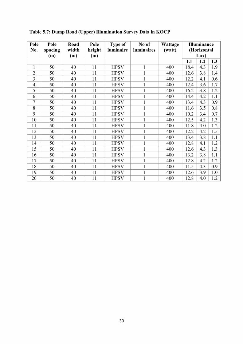
Table 5.7: Dump Road (Upper) Illumination Survey Data in KOCP
Pole
No.
Pole
spacing
(m)
Road
width
(m)
Pole
height
(m)
Type of
luminaire
No of
luminaires
Wattage
(watt)
Illuminance
(Horizontal
Lux)
L1 L2 L3
1 50 40 11 HPSV 1 400 18.4 4.3 1.9
2 50 40 11 HPSV 1 400 12.6 3.8 1.4
3 50 40 11 HPSV 1 400 12.2 4.1 0.6
4 50 40 11 HPSV 1 400 12.4 3.6 1.7
5 50 40 11 HPSV 1 400 16.2 3.8 1.2
6 50 40 11 HPSV 1 400 14.4 4.2 1.1
7 50 40 11 HPSV 1 400 13.4 4.3 0.9
8 50 40 11 HPSV 1 400 11.6 3.5 0.8
9 50 40 11 HPSV 1 400 10.2 3.4 0.7
10 50 40 11 HPSV 1 400 12.5 4.2 1.3
11 50 40 11 HPSV 1 400 11.8 4.0 1.2
12 50 40 11 HPSV 1 400 12.2 4.2 1.5
13 50 40 11 HPSV 1 400 13.4 3.8 1.1
14 50 40 11 HPSV 1 400 12.8 4.1 1.2
15 50 40 11 HPSV 1 400 12.6 4.3 1.3
16 50 40 11 HPSV 1 400 13.2 3.8 1.1
17 50 40 11 HPSV 1 400 12.8 4.2 1.2
18 50 40 11 HPSV 1 400 11.5 4.3 0.9
19 50 40 11 HPSV 1 400 12.6 3.9 1.0
20 50 40 11 HPSV 1 400 12.8 4.0 1.2
31
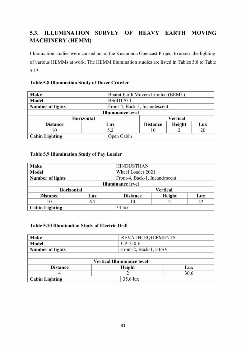
5.3. ILLUMINATION SURVEY OF HEAVY EARTH MOVING
MACHINERY (HEMM)
Illumination studies were carried out at the Kusmunda Opencast Project to assess the lighting
of various HEMMs at work. The HEMM illumination studies are listed in Tables 5.8 to Table
5.13.
Table 5.8 Illumination Study of Dozer Crawler
Make Bharat Earth Movers Limited (BEML)
Model BS6D170-1
Number of lights Front-4, Back-3, Incandescent
Illuminance level
Horizontal Vertical
Distance Lux Distance Height Lux
10 5.2 10 2 20
Cabin Lighting Open Cabin
Table 5.9 Illumination Study of Pay Loader
Make HINDUSTHAN
Model Wheel Loader 2021
Number of lights Front-4, Back-1, Incandescent
Illuminance level
Horizontal Vertical
Distance Lux Distance Height Lux
10 6.7 10 2 42
Cabin Lighting 34 lux
Table 5.10 Illumination Study of Electric Drill
Make REVATHI EQUIPMENTS
Model CP-750 E
Number of lights Front-2, Back-1, HPSV
Vertical Illuminance level
Distance Height Lux
4 2 30.6
Cabin Lighting 35.6 lux
32
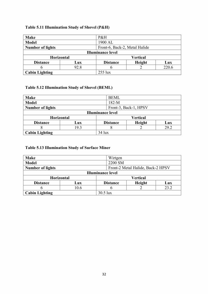
Table 5.11 Illumination Study of Shovel (P&H)
Make P&H
Model 1900 AL
Number of lights Front-6, Back-2, Metal Halide
Illuminance level
Horizontal Vertical
Distance Lux Distance Height Lux
6 92.8 6 2 220.6
Cabin Lighting 255 lux
Table 5.12 Illumination Study of Shovel (BEML)
Make BEML
Model 182-M
Number of lights Front-3, Back-1, HPSV
Illuminance level
Horizontal Vertical
Distance Lux Distance Height Lux
8 19.3 8 2 29.2
Cabin Lighting 34 lux
Table 5.13 Illumination Study of Surface Miner
Make Wirtgen
Model 2200 SM
Number of lights Front-2 Metal Halide, Back-2 HPSV
Illuminance level
Horizontal Vertical
Distance Lux Distance Height Lux
6 10.6 6 2 23.2
Cabin Lighting 30.5 lux
33
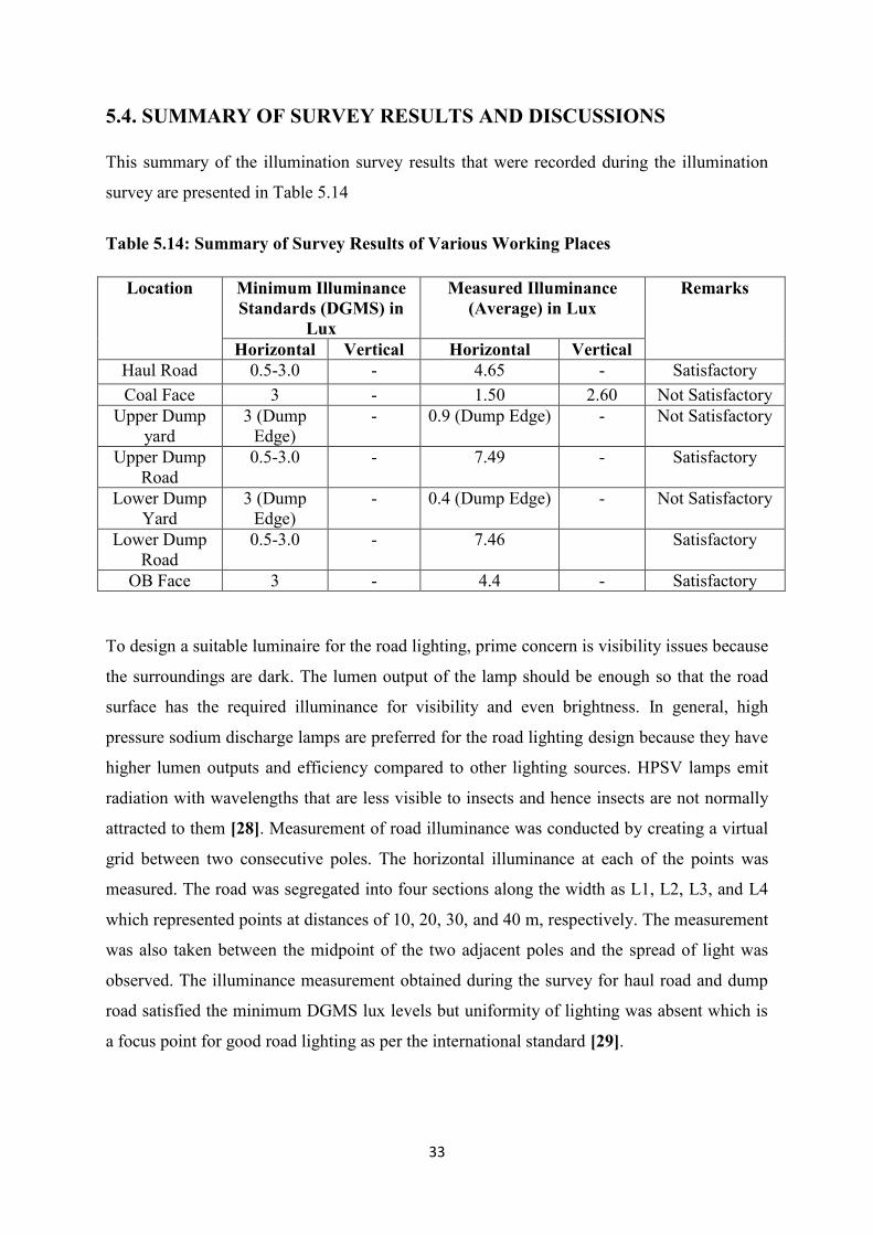
5.4. SUMMARY OF SURVEY RESULTS AND DISCUSSIONS
This summary of the illumination survey results that were recorded during the illumination
survey are presented in Table 5.14
Table 5.14: Summary of Survey Results of Various Working Places
Location Minimum Illuminance
Standards (DGMS) in
Lux
Measured Illuminance
(Average) in Lux
Remarks
Horizontal Vertical Horizontal Vertical
Haul Road 0.5-3.0 - 4.65 - Satisfactory
Coal Face 3 - 1.50 2.60 Not Satisfactory
Upper Dump
yard
3 (Dump
Edge)
- 0.9 (Dump Edge) - Not Satisfactory
Upper Dump
Road
0.5-3.0 - 7.49 - Satisfactory
Lower Dump
Yard
3 (Dump
Edge)
- 0.4 (Dump Edge) - Not Satisfactory
Lower Dump
Road
0.5-3.0 - 7.46 Satisfactory
OB Face 3 - 4.4 - Satisfactory
To design a suitable luminaire for the road lighting, prime concern is visibility issues because
the surroundings are dark. The lumen output of the lamp should be enough so that the road
surface has the required illuminance for visibility and even brightness. In general, high
pressure sodium discharge lamps are preferred for the road lighting design because they have
higher lumen outputs and efficiency compared to other lighting sources. HPSV lamps emit
radiation with wavelengths that are less visible to insects and hence insects are not normally
attracted to them [28]. Measurement of road illuminance was conducted by creating a virtual
grid between two consecutive poles. The horizontal illuminance at each of the points was
measured. The road was segregated into four sections along the width as L1, L2, L3, and L4
which represented points at distances of 10, 20, 30, and 40 m, respectively. The measurement
was also taken between the midpoint of the two adjacent poles and the spread of light was
observed. The illuminance measurement obtained during the survey for haul road and dump
road satisfied the minimum DGMS lux levels but uniformity of lighting was absent which is
a focus point for good road lighting as per the international standard [29].
34
For the dump yard lux levels were checked at the edge of the yard. As, dump edges need to
be seen clearly by the dumper operator hence it is essential to provide adequate illumination
to avoid slide/fall accidents. Lighting arrangement can be provided for the area at a distance
of 100m because of dumper workings and hence symmetrical lighting is used for the purpose.
The installed luminaires on the mine dumping yard were unsymmetrical hence adequate
lighting level was not obtained.
Overburden face lighting was satisfactory as per DGMS standards. The shovel mounted
lights were enough to illuminate the area of 50m x 50m. Peripheral lighting was also
provided. The problem with overburden face lighting occurs when blasting operation is
performed, which totally damages the luminaries. So peripheral lighting cannot be permanent
and hence mobile lighting system e.g. trolley mounted/truck mounted system is
recommended.
Coal face in KOCP was operated by surface miner. It is difficult to provide lighting because
the working face changes rapidly in both direction and depth. Therefore, mobile lighting
arrangements are useful for the purpose, and if any setup may be installed it has to be
repositioned after the face progresses. The current lighting system was provided from the top
of the high-wall side face at a height of 50m, but adequate lighting level is not present
because of the use of asymmetrical lights. Hence, proper changes/adjustments should be done
to accommodate these needs which will improve the visibility conditions of the mine.
35
CHAPTER: 6
DESIGN OF MINE ILLUMNATION SYSTEMS
6.1. INTRODUCTION
Based on illumination requirement in various workplaces in the mine suitable illumination
models were developed and presented in this segment. During the illumination survey, it
was noticed that the existing system of lighting was found inadequate for the mine;
hence a new system of illumination was developed and proposed at appropriate places
where illumination levels were unsatisfactory. In this study, the design of lighting systems was
performed using DIALux software. The illumination level calculations used for the designs
were based on incorporating virtual Philips luminaires and corresponding lamp flux (lumen)
and wattages are given in the design.
6.2. DESIGN OF ILLUMINATION SYSTEMS FOR HAUL ROAD &
DUMP ROAD
The road lighting design utility in the software consists of a tool that is based on the CEN /TR
13201-1 technical report from the European committee for standardization, which helps the
user to determine the ideal illumination conditions based on the user data input e.g. vehicle
speed, difficulty of navigation, road traffic, dust conditions, dry/wet condition of the road
surface, surface reflectance, surface coating, visibility conditions, etc. The illumination
condition obtained for the mine under study was B1 and the illumination class was MEW5
[30]. The reflectance values used for the design were obtained using R3 and W3 tables,
respectively, for the dry and wet conditions, which were integrated in the software. The
simulation was performed by optimizing pole distance, height, inclination, and light overhang.
6.2.1. Design of Haul Road Illumination System
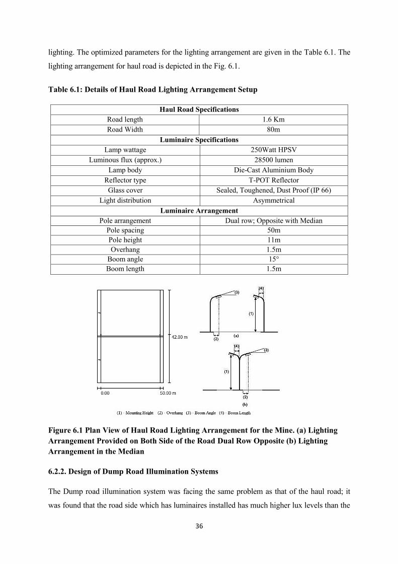
A model for haul road illumination system was simulated which resulted significant
improvement in the uniformity ratio and also low wattage of lamp was used than the existing
36
lighting. The optimized parameters for the lighting arrangement are given in the Table 6.1. The
lighting arrangement for haul road is depicted in the Fig. 6.1.
Table 6.1: Details of Haul Road Lighting Arrangement Setup
Haul Road Specifications
Road length 1.6 Km
Road Width 80m
Luminaire Specifications
Lamp wattage 250Watt HPSV
Luminous flux (approx.) 28500 lumen
Lamp body Die-Cast Aluminium Body
Reflector type T-POT Reflector
Glass cover Sealed, Toughened, Dust Proof (IP 66)
Light distribution Asymmetrical
Luminaire Arrangement
Pole arrangement Dual row; Opposite with Median
Pole spacing 50m
Pole height 11m
Overhang 1.5m
Boom angle 15°
Boom length 1.5m
Figure 6.1 Plan View of Haul Road Lighting Arrangement for the Mine. (a) Lighting
Arrangement Provided on Both Side of the Road Dual Row Opposite (b) Lighting
Arrangement in the Median
6.2.2. Design of Dump Road Illumination Systems
The Dump road illumination system was facing the same problem as that of the haul road; it
was found that the road side which has luminaires installed has much higher lux levels than the
37
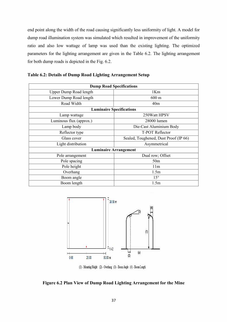
end point along the width of the road causing significantly less uniformity of light. A model for
dump road illumination system was simulated which resulted in improvement of the uniformity
ratio and also low wattage of lamp was used than the existing lighting. The optimized
parameters for the lighting arrangement are given in the Table 6.2. The lighting arrangement
for both dump roads is depicted in the Fig. 6.2.
Table 6.2: Details of Dump Road Lighting Arrangement Setup
Dump Road Specifications
Upper Dump Road length 1Km
Lower Dump Road length 600 m
Road Width 40m
Luminaire Specifications
Lamp wattage 250Watt HPSV
Luminous flux (approx.) 28000 lumen
Lamp body Die-Cast Aluminium Body
Reflector type T-POT Reflector
Glass cover Sealed, Toughened, Dust Proof (IP 66)
Light distribution Asymmetrical
Luminaire Arrangement
Pole arrangement Dual row; Offset
Pole spacing 50m
Pole height 11m
Overhang 1.5m
Boom angle 15°
Boom length 1.5m
Figure 6.2 Plan View of Dump Road Lighting Arrangement for the Mine
38
6.3. Design of Dumping Yard Illumination Systems
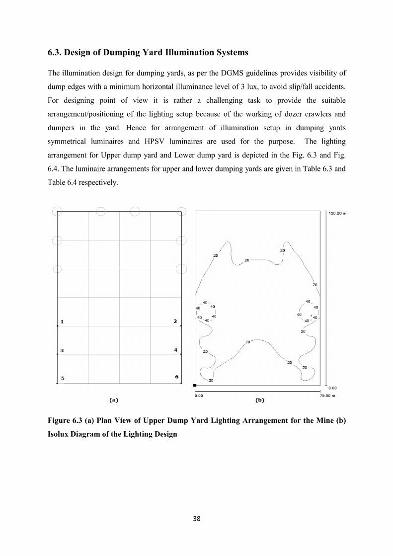
The illumination design for dumping yards, as per the DGMS guidelines provides visibility of
dump edges with a minimum horizontal illuminance level of 3 lux, to avoid slip/fall accidents.
For designing point of view it is rather a challenging task to provide the suitable
arrangement/positioning of the lighting setup because of the working of dozer crawlers and
dumpers in the yard. Hence for arrangement of illumination setup in dumping yards
symmetrical luminaires and HPSV luminaires are used for the purpose. The lighting
arrangement for Upper dump yard and Lower dump yard is depicted in the Fig. 6.3 and Fig.
6.4. The luminaire arrangements for upper and lower dumping yards are given in Table 6.3 and
Table 6.4 respectively.
Figure 6.3 (a) Plan View of Upper Dump Yard Lighting Arrangement for the Mine (b)
Isolux Diagram of the Lighting Design
39
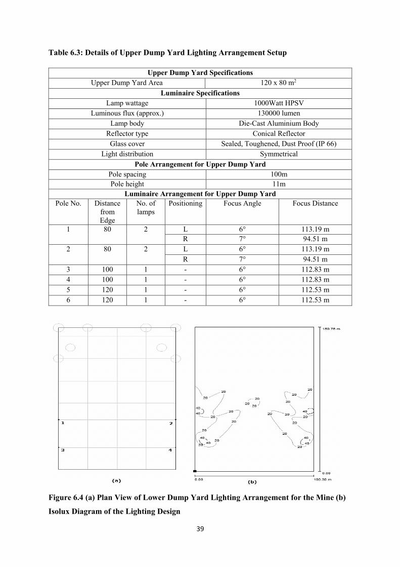
Table 6.3: Details of Upper Dump Yard Lighting Arrangement Setup
Upper Dump Yard Specifications
Upper Dump Yard Area 120 x 80 m2
Luminaire Specifications
Lamp wattage 1000Watt HPSV
Luminous flux (approx.) 130000 lumen
Lamp body Die-Cast Aluminium Body
Reflector type Conical Reflector
Glass cover Sealed, Toughened, Dust Proof (IP 66)
Light distribution Symmetrical
Pole Arrangement for Upper Dump Yard
Pole spacing 100m
Pole height 11m
Luminaire Arrangement for Upper Dump Yard
Pole No. Distance
from
Edge
No. of
lamps
Positioning Focus Angle Focus Distance
1 80 2 L 6° 113.19 m
R 7° 94.51 m
2 80 2 L 6° 113.19 m
R 7° 94.51 m
3 100 1 - 6° 112.83 m
4 100 1 - 6° 112.83 m
5 120 1 - 6° 112.53 m
6 120 1 - 6° 112.53 m
Figure 6.4 (a) Plan View of Lower Dump Yard Lighting Arrangement for the Mine (b)
Isolux Diagram of the Lighting Design
40
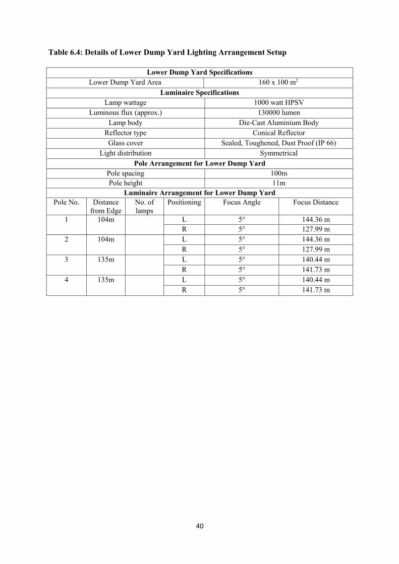
Table 6.4: Details of Lower Dump Yard Lighting Arrangement Setup
Lower Dump Yard Specifications
Lower Dump Yard Area 160 x 100 m2
Luminaire Specifications
Lamp wattage 1000 watt HPSV
Luminous flux (approx.) 130000 lumen
Lamp body Die-Cast Aluminium Body
Reflector type Conical Reflector
Glass cover Sealed, Toughened, Dust Proof (IP 66)
Light distribution Symmetrical
Pole Arrangement for Lower Dump Yard
Pole spacing 100m
Pole height 11m
Luminaire Arrangement for Lower Dump Yard
Pole No. Distance
from Edge
No. of
lamps
Positioning Focus Angle Focus Distance
1 104m L 5° 144.36 m
R 5° 127.99 m
2 104m L 5° 144.36 m
R 5° 127.99 m
3 135m L 5° 140.44 m
R 5° 141.73 m
4 135m L 5° 140.44 m
R 5° 141.73 m
41
CHAPTER: 7
ILLUMINATION DESIGN FOR MOVING COAL &
OVERBURDEN FACE
7.1. INTRODUCTION
Illumination in moving faces is a difficult task to perform because of the advancement of the
working face and hence lighting setups are temporary and has to be change accordingly. Coal
production in KOCP is achieved through surface miner in combination with pay loader. The
approximate cutting depth per day by the surface miner is approximate 1m. Presently, the
mine has two coal faces in which surface miners are operative. A mobile lighting
arrangement or easy to install and maintain lighting arrangement was required for the lighting
of the mine coal faces.
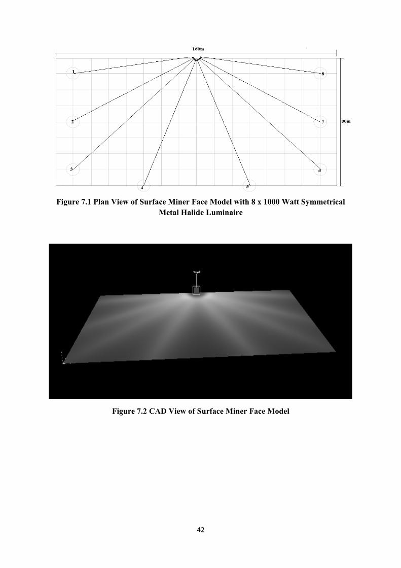
7.2 DESIGN OF MOBILE LIGHTING SYSTEM FOR COAL FACE
For Coal/OB face lighting the design should be mobile so that it can move as the face
progresses. A design was made in the DIALux for the virtual coal face model of KOCP,
using symmetrical metal halide luminaire fittings. The arrangements were tried in three
positions left side corner (position 1), right side corner (position 2) and the center of the high
wall side (position 3) of the surface miner face and the best result for the design is obtained
with the design in position 3. The design consisting of eight symmetrical 1000 watt metal
halide lamps positioned at the center of the face and focused as per the Fig. 7.1. The design
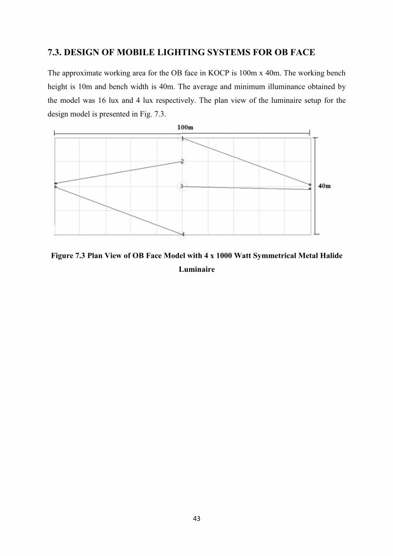
model depicted in Fig. 7.1 and Fig. 7.2 for the above designs represents the plan view of the
design model and the 3D CAD view of the model. The average illuminance obtained by the
model was 9.87 lux and minimum illuminance level was 1.31 lux.
42
Figure 7.1 Plan View of Surface Miner Face Model with 8 x 1000 Watt Symmetrical
Metal Halide Luminaire
Figure 7.2 CAD View of Surface Miner Face Model
43
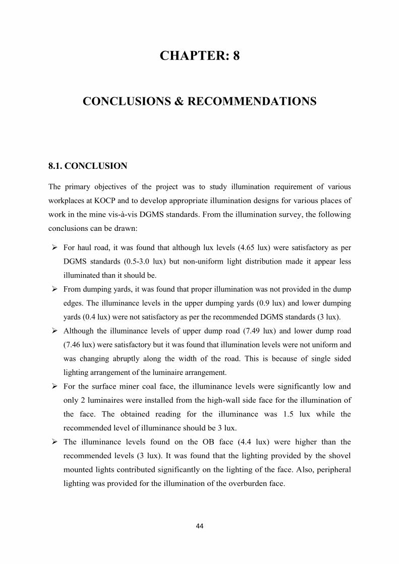
7.3. DESIGN OF MOBILE LIGHTING SYSTEMS FOR OB FACE
The approximate working area for the OB face in KOCP is 100m x 40m. The working bench
height is 10m and bench width is 40m. The average and minimum illuminance obtained by
the model was 16 lux and 4 lux respectively. The plan view of the luminaire setup for the
design model is presented in Fig. 7.3.
Figure 7.3 Plan View of OB Face Model with 4 x 1000 Watt Symmetrical Metal Halide
Luminaire
44
CHAPTER: 8
CONCLUSIONS & RECOMMENDATIONS
8.1. CONCLUSION
The primary objectives of the project was to study illumination requirement of various
workplaces at KOCP and to develop appropriate illumination designs for various places of
work in the mine vis-à-vis DGMS standards. From the illumination survey, the following
conclusions can be drawn:
For haul road, it was found that although lux levels (4.65 lux) were satisfactory as per
DGMS standards (0.5-3.0 lux) but non-uniform light distribution made it appear less
illuminated than it should be.
From dumping yards, it was found that proper illumination was not provided in the dump
edges. The illuminance levels in the upper dumping yards (0.9 lux) and lower dumping
yards (0.4 lux) were not satisfactory as per the recommended DGMS standards (3 lux).
Although the illuminance levels of upper dump road (7.49 lux) and lower dump road
(7.46 lux) were satisfactory but it was found that illumination levels were not uniform and
was changing abruptly along the width of the road. This is because of single sided
lighting arrangement of the luminaire arrangement.
For the surface miner coal face, the illuminance levels were significantly low and
only 2 luminaires were installed from the high-wall side face for the illumination of
the face. The obtained reading for the illuminance was 1.5 lux while the
recommended level of illuminance should be 3 lux.
The illuminance levels found on the OB face (4.4 lux) were higher than the
recommended levels (3 lux). It was found that the lighting provided by the shovel
mounted lights contributed significantly on the lighting of the face. Also, peripheral
lighting was provided for the illumination of the overburden face.
45
Based on the shortcoming of the existing illumination levels at different place of
work, effective and appropriate and modified illumination of lighting system was
proposed using DIALux software which can enhance the working conditions in a much
better way.
8.2. RECOMMENDATIONS
The following recommendations have been proposed to improve the visual level in the work
places and are stated below:
Installation of 150W HPSV luminaires for roads not exceeding length of 1 km and 250W
HPSV luminaires for length exceeding 1 km and other installation details should follow
the given design.
Installation of Metal Halide luminaires for coal faces and HPSV for OB faces.
Luminaires should be die cast aluminum built.
Truck mounted illumination system can be used instead of fixed lighting system at coal
face.
46
REFERENCES
1. Ganslandt, R., & Hofmann, H. Handbook of Lighting Design. New York (USA), Verlag
Vieweg, 1992.
2. Hartman, H. L. SME Mining Engineering Handbook (2nd Edition, Vol. 1). Colorado
(USA), Society for Mining, Metallurgy, and Exploration, Inc., 1992.
3. Taylor, A. E. Illumination Fundamentals. New York (USA), Lighting Research Center,
Rensselaer Polytechnic Institute, 2000.
4. Lighting Planning-Quantities, Units and Their Significance. Habo (Sweden), Fagerhult
Group.
5. Halonen, L., Tetri, E., & Bhusal, P. Guidebook on Energy Efficient Electric Lighting for
Buildings. Espoo (Finland), Lighting Unit, Department of Electronics, School Of Science
and Technology, Aalto University, 2010.
6. Directorate General of Mines Safety. Legis. Circular No. 1. Dhanbad (India): DGMS
(1976): pp. 385.
7. Rushworth, A. M., Talbot, C. F., Von Glehn, F. H., Lomas, R. M., & Franz, R. M. Role
of Illumination in Reducing Risk to Health and Safety in South African Gold and
Platinum Mines. Pretoria (South Africa), Safety in Mines Research Advisory Committee,
2001.
8. Van Graan, C.H., & Schutte, P.C. Underground Illumination and The Selection of Heavy
Vehicle Drivers: De Beers Consolidated Mines. Johannesburg (South Africa), Chamber
of Mines of South Africa. Research Organization Research Report No. 63/77, Project No.
AX6H01C (1997), pp. 15.
9. Mishra, V.S., & Dixit, J.P. A New Psycho Engineering Strategy for Safety in Mines:
Indian Mining and Engineering Journal (1978); pp. 7-12.
10. Trotter, D.A. The lighting of underground mines. Montreal (Canada): Trans Tech
Publications.1982.
11. Franz, M., Ashworth, G., & Mthombeni, I.S. The Role of Environmental Factors in Mine
Accidents. Pretoria (South Africa): Department of Minerals and Energy. SIMRAC
Research Project GAP 203 (1995), pp. 1-182.
47
12. Mayton, A.G. Assessment and Determination of Illumination Needs for Operators of
Mobile Surface Mining Equipment. Pittsburgh (USA): U.S. Department of the Interior,
Bureau of Mines. Report No. IC 9153 (1987), pp. 37.
13. Odendaal, E.P.S. The Consequences of Poor Illumination on Underground Mine Workers
and the Subsequent Effects on Productivity and Safety [Doctoral Thesis]. Johannesburg
(South Africa): University of the Witwatersrand, 1996, pp. 220.
14. Sammarco, J.J., Reyes, M.A., Bartels, J., & Gallagher, S. Evaluation of Peripheral Visual
Performance When Using Incandescent and LED Miner Cap Lamps. IEEE Industry
Applications. 45(6) (2009): pp. 1923-1929.
15. Sammarco, J.J., & Yenchek, M.R. The Potential Impact of Light Emitting Diode Lighting
on Reducing Mining Injuries during Operation and Maintenance of Lighting Systems.
Elsevier Safety Science. 48(10) (2010): pp. 1380-1386.
16. Sammarco, J.J., & Lutz, T.J. Visual Performance for Incandescent and Solid-State Cap
Lamps in an Underground Mining Environment. Proceedings of the IEEE Industry
Applications Society 42nd Annual Meeting, New Orleans (USA) (2007): pp. 2090-2095.
17. Sammarco, J.J., Mayton, A., Lutz, T.J., & Gallagher, S. Evaluation of Glare for
Incandescent and LED Miner Cap Lamps in Mesopic Conditions. CDC, Mining
Engineering. 61(6) (2009): pp. 99-106.
18. Tyson, J. To See or Not to See: That is The Question! Designing To Maximize Operator
Visibility in LHD Equipment. North Bay (Canada): Ontario Natural Resources Safety
Association (1999).
19. Mayton, A.G. Investigation of Task Illumination for Surface Coal Mining Equipment
Operators. Journal of Illuminating Engineering Society. 20(1) (1991): pp. 2-18.
20. Karmakar, N.C., Aruna, M., & Rao. Y.V. Development of Computer Models for Design
and Economic Analysis of Lighting Systems in Surface Mines. 20th World Mining
Congress on Mining and Sustainable Development, Tehran (Iran) (2005): pp. 541-543.
21. Aruna, M., & Jaralikar, S.M. Design of Lighting System for Surface Mine Projects.
TELKOMNIKA. 10(2) (2012): pp. 235-244.
22. Das, R.C., & Roul, A. Illumination Design in A Highly Mechanized Opencast Bauxite
Mine. Conference on Technological Advancements and Environmental Challenges in
Mining and allied Industries in the 21st Century, NIT, Rourkela (India) (2005): pp. 369-
380.
48
23. Pal, N., Krishna, V.S., Gupta, R.P., Kumar, A., & Prasad, U. Haul Roads Lighting System
for Open Cast Mine Using Green Energy. Proceedings of the International Multi-
Conference of Engineers and Computer Scientists, Hong Kong, 3 (2012): pp. 987-990.
24. Benya, J., & Schwartz, P. Advanced Lighting Guidelines. White Salmon (USA), New
Buildings Institute, 2001.
25. Rea, M. S. The IESNA Lighting Handbook: Reference & Application. New York (USA),
Illuminating Engineering Society of North America, 2000.
26. Land Restoration/Reclamation Monitoring of 50 Opencast Coal Mines of CIL producing
more than 5 mcm (Coal+OB) based on Satellite Data for the Year 2012-13, Annual
Report, CMPDI
27. Kusmunda Opencast Coal Mining Project. 2012. Annual Report, South Eastern Coalfields
Limited. Chhattisgarh (India): KOCP
28. Barghini, A., & Medeiros, B.A.S. UV Radiation as an Attractor for Insects. LEUKOS.
9(1) (2012): pp. 47-56.
29. Comité Européen de Normalisation. CEN/TR 13201-1 Technical Report: Road lighting-
Part 1: Selection of Lighting Classes, 2004.
30. Commission Internationale de l’Eclairage. Fundamentals of the Visual Task of Night
Driving CIE 100-1992. Vienna (Austria), 1992.
31. <http://www.lynx-india.com/index.php?productID=18309> Accessed 2014 May 10.
32. < http://www.citelum.com.au/city-of-greater-shepparton> Accessed 2014 May 10.
33. <http://en.wikipedia.org/wiki/Korba_Coalfield> Accessed 2013 December 10.