Embed Size (px)
Citation preview
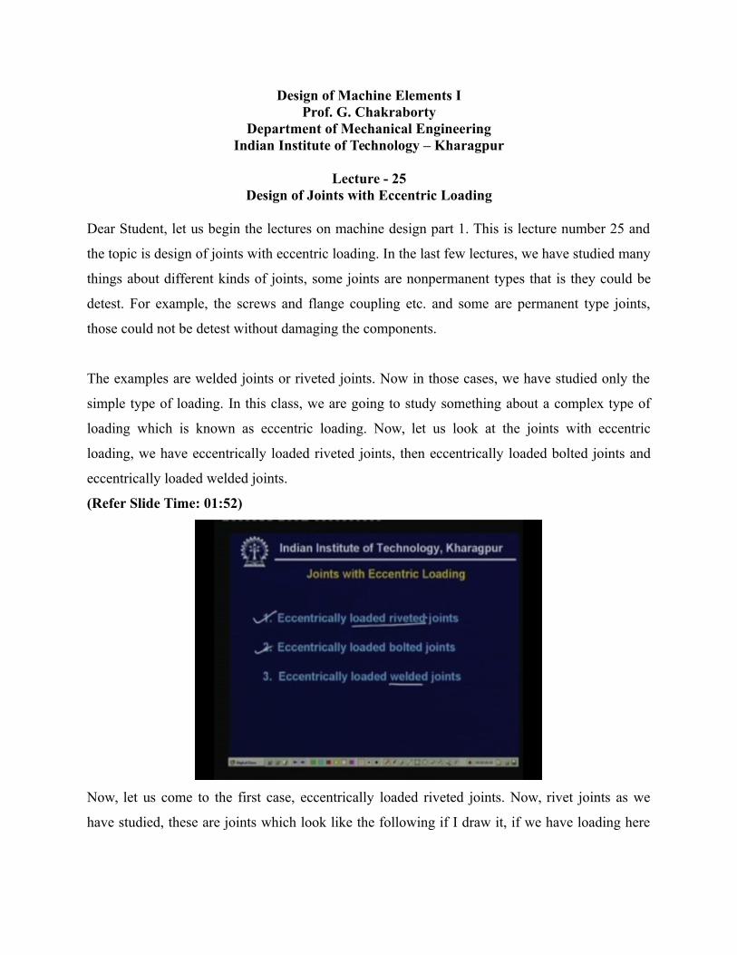
Design of Machine Elements IProf. G. Chakraborty
Department of Mechanical EngineeringIndian Institute of Technology – Kharagpur
Lecture - 25Design of Joints with Eccentric Loading
Dear Student, let us begin the lectures on machine design part 1. This is lecture number 25 and
the topic is design of joints with eccentric loading. In the last few lectures, we have studied many
things about different kinds of joints, some joints are nonpermanent types that is they could be
detest. For example, the screws and flange coupling etc. and some are permanent type joints,
those could not be detest without damaging the components.
The examples are welded joints or riveted joints. Now in those cases, we have studied only the
simple type of loading. In this class, we are going to study something about a complex type of
loading which is known as eccentric loading. Now, let us look at the joints with eccentric
loading, we have eccentrically loaded riveted joints, then eccentrically loaded bolted joints and
eccentrically loaded welded joints.
(Refer Slide Time: 01:52)
Now, let us come to the first case, eccentrically loaded riveted joints. Now, rivet joints as we
have studied, these are joints which look like the following if I draw it, if we have loading here
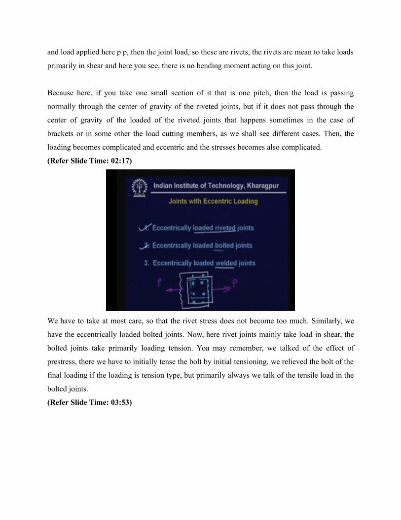
and load applied here p p, then the joint load, so these are rivets, the rivets are mean to take loads
primarily in shear and here you see, there is no bending moment acting on this joint.
Because here, if you take one small section of it that is one pitch, then the load is passing
normally through the center of gravity of the riveted joints, but if it does not pass through the
center of gravity of the loaded of the riveted joints that happens sometimes in the case of
brackets or in some other the load cutting members, as we shall see different cases. Then, the
loading becomes complicated and eccentric and the stresses becomes also complicated.
(Refer Slide Time: 02:17)
We have to take at most care, so that the rivet stress does not become too much. Similarly, we
have the eccentrically loaded bolted joints. Now, here rivet joints mainly take load in shear, the
bolted joints take primarily loading tension. You may remember, we talked of the effect of
prestress, there we have to initially tense the bolt by initial tensioning, we relieved the bolt of the
final loading if the loading is tension type, but primarily always we talk of the tensile load in the
bolted joints.
(Refer Slide Time: 03:53)
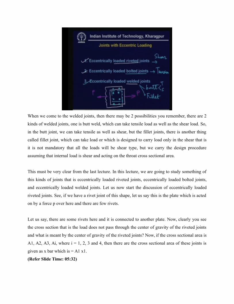
When we come to the welded joints, then there may be 2 possibilities you remember, there are 2
kinds of welded joints, one is butt weld, which can take tensile load as well as the shear load. So,
in the butt joint, we can take tensile as well as shear, but the fillet joints, there is another thing
called fillet joint, which can take load or which is designed to carry load only in the shear that is
it is not mandatory that all the loads will be shear type, but we carry the design procedure
assuming that internal load is shear and acting on the throat cross sectional area.
This must be very clear from the last lecture. In this lecture, we are going to study something of
this kinds of joints that is eccentrically loaded riveted joints, eccentrically loaded bolted joints,
and eccentrically loaded welded joints. Let us now start the discussion of eccentrically loaded
riveted joints. See, if we have a rivet joint of this shape, let us say this is the plate which is acted
on by a force p over here and there are few rivets.
Let us say, there are some rivets here and it is connected to another plate. Now, clearly you see
the cross section that is the load does not pass through the center of gravity of the riveted joints
and what is meant by the center of gravity of the riveted joints? Now, if the cross sectional area is
A1, A2, A3, Ai, where i = 1, 2, 3 and 4, then there are the cross sectional area of these joints is
given as x bar which is = A1 x1.
(Refer Slide Time: 05:32)
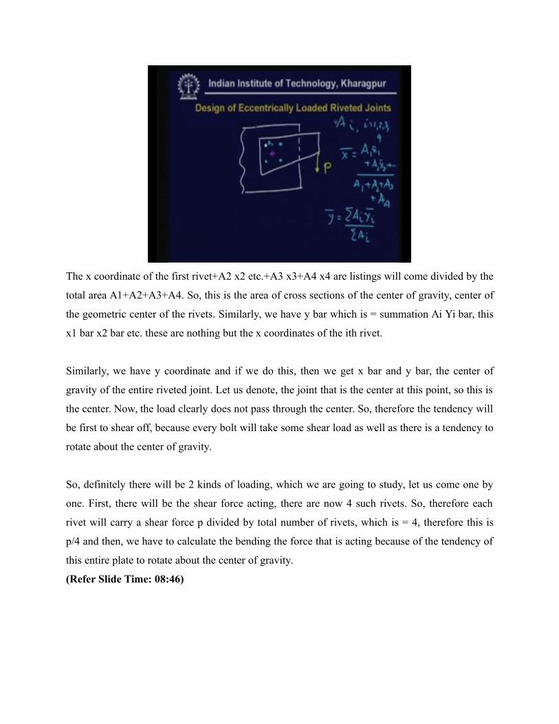
The x coordinate of the first rivet+A2 x2 etc.+A3 x3+A4 x4 are listings will come divided by the
total area A1+A2+A3+A4. So, this is the area of cross sections of the center of gravity, center of
the geometric center of the rivets. Similarly, we have y bar which is = summation Ai Yi bar, this
x1 bar x2 bar etc. these are nothing but the x coordinates of the ith rivet.
Similarly, we have y coordinate and if we do this, then we get x bar and y bar, the center of
gravity of the entire riveted joint. Let us denote, the joint that is the center at this point, so this is
the center. Now, the load clearly does not pass through the center. So, therefore the tendency will
be first to shear off, because every bolt will take some shear load as well as there is a tendency to
rotate about the center of gravity.
So, definitely there will be 2 kinds of loading, which we are going to study, let us come one by
one. First, there will be the shear force acting, there are now 4 such rivets. So, therefore each
rivet will carry a shear force p divided by total number of rivets, which is = 4, therefore this is
p/4 and then, we have to calculate the bending the force that is acting because of the tendency of
this entire plate to rotate about the center of gravity.
(Refer Slide Time: 08:46)
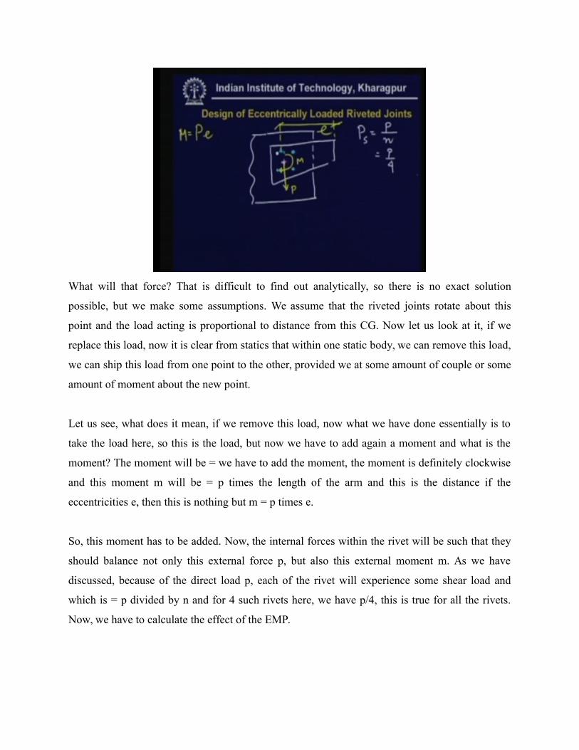
What will that force? That is difficult to find out analytically, so there is no exact solution
possible, but we make some assumptions. We assume that the riveted joints rotate about this
point and the load acting is proportional to distance from this CG. Now let us look at it, if we
replace this load, now it is clear from statics that within one static body, we can remove this load,
we can ship this load from one point to the other, provided we at some amount of couple or some
amount of moment about the new point.
Let us see, what does it mean, if we remove this load, now what we have done essentially is to
take the load here, so this is the load, but now we have to add again a moment and what is the
moment? The moment will be = we have to add the moment, the moment is definitely clockwise
and this moment m will be = p times the length of the arm and this is the distance if the
eccentricities e, then this is nothing but m = p times e.
So, this moment has to be added. Now, the internal forces within the rivet will be such that they
should balance not only this external force p, but also this external moment m. As we have
discussed, because of the direct load p, each of the rivet will experience some shear load and
which is = p divided by n and for 4 such rivets here, we have p/4, this is true for all the rivets.
Now, we have to calculate the effect of the EMP.
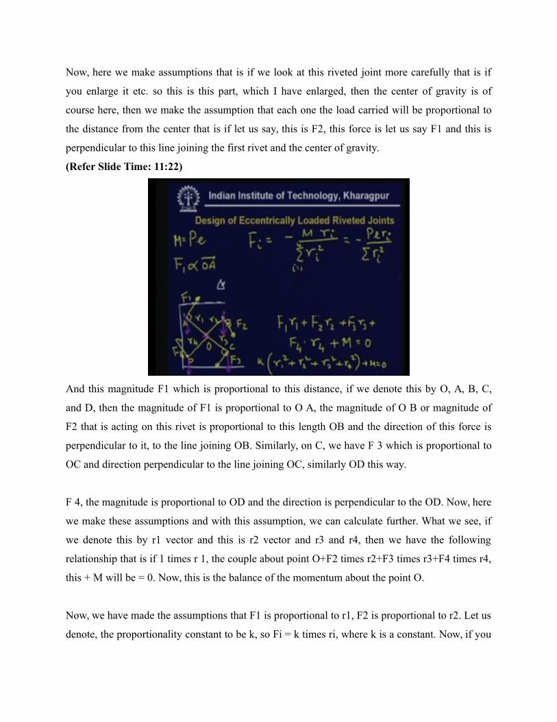
Now, here we make assumptions that is if we look at this riveted joint more carefully that is if
you enlarge it etc. so this is this part, which I have enlarged, then the center of gravity is of
course here, then we make the assumption that each one the load carried will be proportional to
the distance from the center that is if let us say, this is F2, this force is let us say F1 and this is
perpendicular to this line joining the first rivet and the center of gravity.
(Refer Slide Time: 11:22)
And this magnitude F1 which is proportional to this distance, if we denote this by O, A, B, C,
and D, then the magnitude of F1 is proportional to O A, the magnitude of O B or magnitude of
F2 that is acting on this rivet is proportional to this length OB and the direction of this force is
perpendicular to it, to the line joining OB. Similarly, on C, we have F 3 which is proportional to
OC and direction perpendicular to the line joining OC, similarly OD this way.
F 4, the magnitude is proportional to OD and the direction is perpendicular to the OD. Now, here
we make these assumptions and with this assumption, we can calculate further. What we see, if
we denote this by r1 vector and this is r2 vector and r3 and r4, then we have the following
relationship that is if 1 times r 1, the couple about point O+F2 times r2+F3 times r3+F4 times r4,
this + M will be = 0. Now, this is the balance of the momentum about the point O.
Now, we have made the assumptions that F1 is proportional to r1, F2 is proportional to r2. Let us
denote, the proportionality constant to be k, so Fi = k times ri, where k is a constant. Now, if you
substitute this into this equations, what you get is k times r1 square+r2 square+r3 square+r4
square+m = 0, so this is the equation which you get. From this, you can solve for k.
Directly, what you see is that the value of k now is let us write down in for more legible form,
what you have then Fi = k, which is = - m divided by summation ri square, i is 1 to 4 and times ri
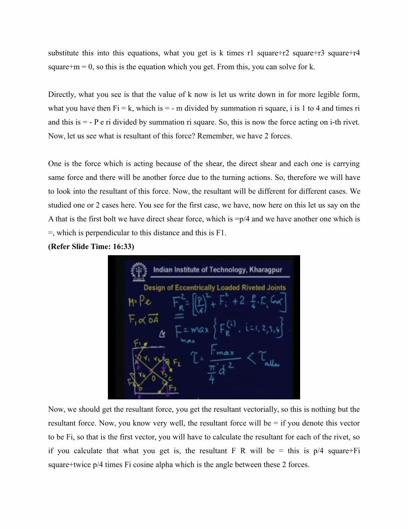
and this is = - P e ri divided by summation ri square. So, this is now the force acting on i-th rivet.
Now, let us see what is resultant of this force? Remember, we have 2 forces.
One is the force which is acting because of the shear, the direct shear and each one is carrying
same force and there will be another force due to the turning actions. So, therefore we will have
to look into the resultant of this force. Now, the resultant will be different for different cases. We
studied one or 2 cases here. You see for the first case, we have, now here on this let us say on the
A that is the first bolt we have direct shear force, which is =p/4 and we have another one which is
=, which is perpendicular to this distance and this is F1.
(Refer Slide Time: 16:33)
Now, we should get the resultant force, you get the resultant vectorially, so this is nothing but the
resultant force. Now, you know very well, the resultant force will be = if you denote this vector
to be Fi, so that is the first vector, you will have to calculate the resultant for each of the rivet, so
if you calculate that what you get is, the resultant F R will be = this is p/4 square+Fi
square+twice p/4 times Fi cosine alpha which is the angle between these 2 forces.
So, therefore for each of the bolt, you will have to carry these calculations. You will have to
make these calculations and you will have to find the highest, the largest F R that is the rivet
which has the largest shear of the load. Now, you will have to design the rivet such that the
maximum stress in the bolt is below the allowable limit. So, with the help of these calculations,
you first calculate what is the maximum of FRi, where i = 1, 2, 3, 4, there are 4 such cases.
So, you get this maximum force F max and then you calculate the stress. Now, the shear stress F
max divided by pi/ 4 d square and that must be less tau allowable, so this is the design criteria for
eccentrically loaded riveted joint. Now, let me repeat again, we make the assumption that
whenever we have eccentrically loaded joint, the turning action around the geometric center of
gravity of the riveted joint will be such that the force in each of the rivet will be proportional to
distance of the rivet from the center and the direction will be perpendicular to the line joining the
point the center of gravity and the corresponding rivet.
So, with this assumption we make these calculations. We find out the maximum force in such
rivet assembly and then with the maximum force, we calculate the maximum shear stress taken
by this bolt and hence we calculate the corresponding diameter that is we design the joint. So,
this is the design procedure for eccentrically loaded riveted joints. Now, let us go to the design of
eccentrically loaded bolted joint.
(Refer Slide Time: 20:54)

Here we have 2 cases distinct, first let us take the example. Here consider this kind of bracket,
there are bolts here, so if you look from this side top, you will see. Now these are bolt, let us say
cross section 1, section 2, so there are 4 such bolt I and II and the load is acting here, there is a
load p acting. Now, you see what will be the effect of p? Now, the p will introduce tension in the
bolted assembly.
So, each bolt will carry some tension, but the tension will not be uniform because there is the
distinct tendency for this bracket to rotate about this point, let us say point A, so there is a
tendency that it will rotate about this point because of this load. So, therefore the tension in the
bolt will be unequal. Now, again what we see, now how to calculate the tensile load in the
member?
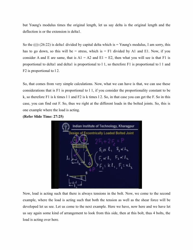
We will make the static equilibrium that is let us say that each of the bolt here carries a load F1
and F2. Now, if you write down the static equilibrium equations, then F1, there are 2 such 1 and
2, 2 F1+2 F2 will be = p and that is the only static equilibrium equations we have for this case.
Now, this is statically indeterminate problem. Therefore, because we have 2 unknowns and one
equation only.
So, it cannot be solved by means of pure statics only. So, we will have to take help of now
kinematics that is the flexibility of this member. Now, if you take the consideration of flexibility,

we make the assumptions that here this body is the rigid body, this bracket is a rigid body, so
therefore when it rotates, suppose it rotates, then because of rotation it will come to some this
kind of position, because it has rotated.
So, this was the original position and this is the final position. Now, it has rotated. Therefore,
there is small deflections of these 2 bolts. There will be some elongations of this bolt if you draw
it elaborately. Then, what you see here, this was the initial line and after that it has rotated here,
so now if you denote this length, length from this point to that point by l 1 and from here to there
l 2, then what you will get is that this is l 1, this point A and point B.
(Refer Slide Time: 24:29)
So, this is l 1 and this one is l 2. Now, the delta that is delta1 that is the deflection of this is now
proportional to this length l 1 that is clearly visible because this is the rigid plate, so this angle is
constant. So, tangent of this angle will be = delta1 divided by this length l 1 and the tangent of
this angle will be again = delta2 which is the deflections of this bolt divided by the entire length l
2.
So, therefore delta1 is proportional to l 1 and delta2 is proportional to l 2. Then, if you use the
Hooke's law, then what you will get is that F is, F1 ultimately could be written is F1 is
proportional to l 1 and F2 is proportional to l 2 that is clearly visible because delta1 is nothing
but Young's modulus times the original length, let us say delta is the original length and the
deflection is or the extension is delta1.
So the (()) (26:22) is delta1 divided by capital delta which is = Young's modulus, I am sorry, this
has to go down, so this will be = stress, which is = F1 divided by A1 and E1. Now, if you
consider A and E are same, that is A1 = A2 and E1 = E2, then what you will see is that F1 is
proportional to delta1 and delta1 is proportional to l 1, so therefore F1 is proportional to l 1 and
F2 is proportional to l 2.
So, that comes from very simple calculations. Now, what we can have is that, we can use these
considerations that is F1 is proportional to l 1, if you consider the proportionality constant to be
k, so therefore F1 is k times l 1 and F2 is k times l 2. So, in that case you can get the F. So in this
case, you can find out F. So, thus we right at the different loads in the bolted joints. So, this is
one example where the load is acting.
(Refer Slide Time: 27:25)
Now, load is acting such that there is always tensions in the bolt. Now, we come to the second
example, where the load is acting such that both the tension as well as the shear force will be
developed let us see. Let us come to the next example. Here we have, now here and we have let
us say again some kind of arrangement to look from this side, then at this bolt, thus 4 bolts, the
load is acting over here.
(Refer Slide Time: 28:34)
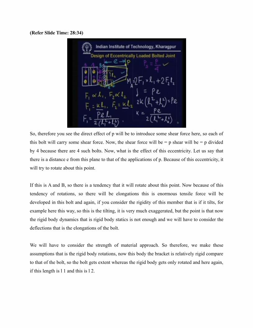
So, therefore you see the direct effect of p will be to introduce some shear force here, so each of
this bolt will carry some shear force. Now, the shear force will be = p shear will be = p divided
by 4 because there are 4 such bolts. Now, what is the effect of this eccentricity. Let us say that
there is a distance e from this plane to that of the applications of p. Because of this eccentricity, it
will try to rotate about this point.
If this is A and B, so there is a tendency that it will rotate about this point. Now because of this
tendency of rotations, so there will be elongations this is enormous tensile force will be
developed in this bolt and again, if you consider the rigidity of this member that is if it tilts, for
example here this way, so this is the tilting, it is very much exaggerated, but the point is that now
the rigid body dynamics that is rigid body statics is not enough and we will have to consider the
deflections that is the elongations of the bolt.
We will have to consider the strength of material approach. So therefore, we make these
assumptions that is the rigid body rotations, now this body the bracket is relatively rigid compare
to that of the bolt, so the bolt gets extent whereas the rigid body gets only rotated and here again,
if this length is l 1 and this is l 2.
What we have is that l 1 that is this force again from the same calculation as before, this force on
this first bolt that is this bolt again will be F1 which is proportional to l 1 this is why because we
see delta1, the elongations of this bolt that is of this bolt, the elongation will be delta1 and this is
proportional to l 1 and that is because this angle is constant. Again, the tangent of this angle will
be = delta1 divided by l 1.
Again, the tangent of this angle will be also = delta2 divided by l 2, so delta1 and delta2 are
proportional to l 1 and l 2 respectively. Now, again if you use the Hooke's law, you get that F1
and F2 are proportional to l 1 and l 2. If you use this proportionality constant to be k, then what
you get is F1 is k l 1, F2 is k l 2. Now, you have already used the equilibrium equations, force
equilibrium equations, already we are left with the moment equilibrium equations.
Let us use the moment equilibrium equation now. If you take the moment about this point, what
you get is that F 1, let us consider this direction of this force is here F1 and F2, then we have F1
times l 1, the moment about point A, F1 l 1+F1 l 1 because there are 2 such bolts, so twice F1 l
1+F2 l 2. Again, twice of that, this is = the external moment, which is = p times e.
Now, if you use this relationship that is F1 and F2 are proportional to l 1 and l 2 respectively,
then what you get from this equation is twice k l 1 square + l 2 square will be = p e. From this,
you calculate k which is = p e divided by twice l 1 square + l 2 square. Once we have calculated
k, then we have calculated F1 because F1 will be = k times l 1, so this is = pel1 divided by twice
l 1 square + l 2 square.
Similarly, F2 will be = p e l 2 divided by twice l 1 square + l 2 square. Now, let us sum it up we
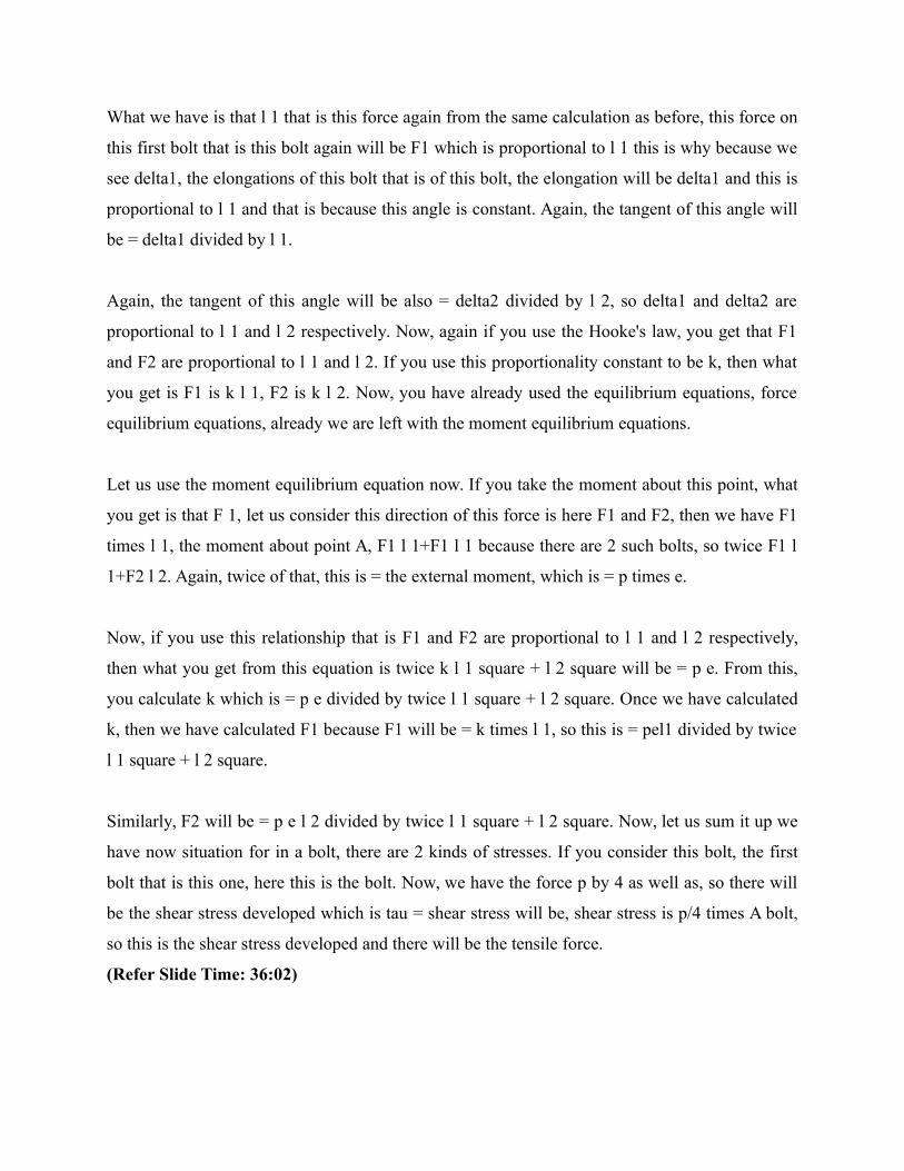
have now situation for in a bolt, there are 2 kinds of stresses. If you consider this bolt, the first
bolt that is this one, here this is the bolt. Now, we have the force p by 4 as well as, so there will
be the shear stress developed which is tau = shear stress will be, shear stress is p/4 times A bolt,
so this is the shear stress developed and there will be the tensile force.
(Refer Slide Time: 36:02)

The tensile force is again F1, which is given as pel1 by twice l 1 square + l 2 square. Definitely,
F2 is much larger compared to F1. So, therefore the tensile force will larger for the second bolt,
this bolt. So, when we have to find out the cross-sectionally of the bolt that is when you want to
design the bolt, then we will have to consider the maximum of the stresses. So, we consider the
second bolt, the first bolt keeps the tensile stress F1 divided by.
Sigma will be = F1 by A bolt, but F1 < F2, so therefore, the maximum tensile force will be taken
by the second bolt and we will have to consider the design with the second bolt itself, but not the
first bolt. So, if you consider the second bolt, what you get is the same shear force, but here F2,
tau remains same, sigma becomes instead of F1, we have F2 and divided by A b.
Now, we have the case where the bolt is subjected to both shear and the tensile force. Now,
normally as I said, the bolts are not mean to carry the shear load. Primarily, the bolts should carry
only the tensile load, but if sometimes shear load occurs, then we will have to relieve the bolts of
the shear load if possible. So, that is done by say adding some kind of other bolts (()) (38:44) etc.
So, this should take of the shear load as small as possible.
So, if you increase the number of bolts over here, then the shear load may be decreased. So, this
is done, the shear load is reduced as far as possible, but if further is not possible, then we will
have to consider the effect of the shear stress as well as the normal stress. We have the shear
stress and the normal stress and then we calculate the von Mises stress.
You know that when we have both the stresses, we can calculate sometimes the von Mises
stresses which is = sigma square + thrice tau square, this is one failure criteria where the material
fails, if this is > if sigma allowable. Another failure criteria is the maximum shear stress, which is
tau max will be = sigma by 2 square + tau square and this must be, so these are the 2 criteria by
which the ductile material will fail.
If it is made of brittle material, which seldom happens, then we will have to consider the
maximum principle stress and that is given by (()) (40:25) formula that is sigma/2 + on the root
sigma/2 square + tau square and if the material is brittle nature, then this should be < sigma
allowable. So, these are few failure criteria, which we left consider, but the important point is
that here the bolts are subjected to both shear stress as well as normal stress.
(Refer Slide Time: 40:32)
And when you have to calculate the normal stress, you will have to make these assumptions that
the bracket is more rigid compare to that of the bolt, so therefore the bracket actually rotates one
of the points, but the bolts will get elongated and the forces will be found out accordingly using
the geometrical relationship, so that must be clear. This is again a case where statical
determinacy does not exist.
So, this is statically indeterminate problem and we will have to take the help of the flexibility of
the members. Now, this is about the design of eccentrically loaded bolted joint. Remember, I
repeat we have considered 2 cases. In one case, the load is acting such a way that the bolts are
entirely under tension. There is no shear force as we have seen from the first example. In the
second example, the bolts are now on the shear because of the direct action of this force and it is
again partly under tension because of this eccentricity.
So, eccentricity makes the joints, the design of joints quite complicated as you might have
understood by now. So, this is about the eccentrically loaded bolted joint. Now, we come to the
third case, where we have the eccentrically loaded welded joint. There are again few examples,
we will take one by one. Let us consider the case, where a plate is welded to a structure. Now,
the welding can be done in various ways.
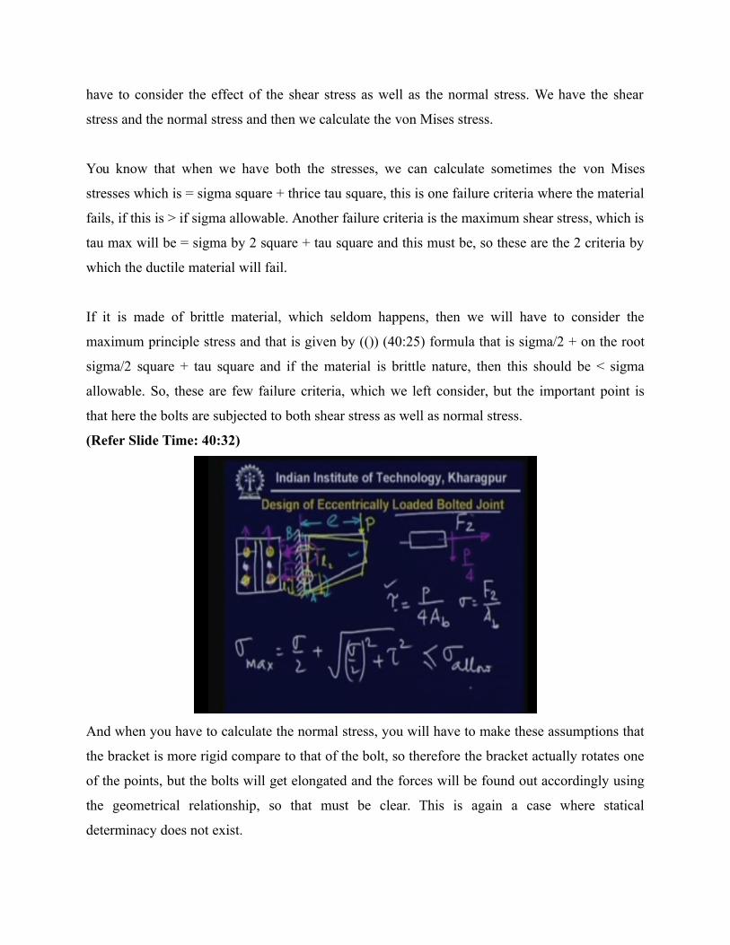
(Refer Slide Time: 42:52)
The welding may be this side that is it maybe a transverse fillet welding. There are 2 kinds of
welding, one is butt welding and another is fillet welding. Normally, in this case, we use the fillet
welding. There may be again 2 types of fillet welding. One is transverse fillet and another is the
longitudinal or parallel fillet. Let us say that here, this is in parallel fillet, so we have the fillet
joints here, fillet joints over here and the load is now eccentric loading and in these directions.
Remember, in earlier classes, we have studied the design of this joint, this welded joint. In that
case, the load was along these directions, but now instead we have load in the other directions, so
what is the effect of that? That is what we are going to study. Now, we see here if you look little
bit closely then what you see the fillet weld looks like this, so this is the plate and this is the
welded part.
So, this is the fillet and the critical section is the section of the throat that is this section, so this is
the critical section and the failure may take place in this section itself. Now, when we consider
the eccentrically loaded joint, what we see that in addition to the shear force, there may be then 2
cases, there are 2 kinds of stresses, the direct shear force, direct shear stress and what is the direct
shear stress?
The direct shear stress value is = tau will be = p divided by twice because there are 2 such welds
divided twice area of the throat and what is the area of the throat? If this less height is h,
normally the fillets will have equal dimensions this is 45 degree angle, so therefore the At will be
= throat times the length. If these 2 lengths are equal, then of course area will be = t times l and
this is = h/root 2 times l.
And therefore, the shear stress will be = p divided by twice h by root 2 l, so this is the direct
shear force, which is acting on this joint, but what will the effect of eccentricity? We see that
eccentricity will try to rotate this entire plate about some access and what is that access. Thus,
this access is nothing but the center of gravity that is the geometric center of this welding that is
there are 2 welds and we can define always one center here, which is the geometric center.
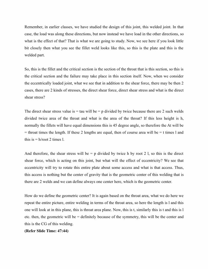
How do we define the geometric center? It is again based on the throat area, what we do here we
repeat the entire picture, entire welding in terms of the throat area, so here the length is l and this
one will look at in this plane, this is throat area plane. Now, this is t, similarly this is t and this is l
etc. then, the geometric will be = definitely because of the symmetry, this will be the center and
this is the CG of this welding.
(Refer Slide Time: 47:44)
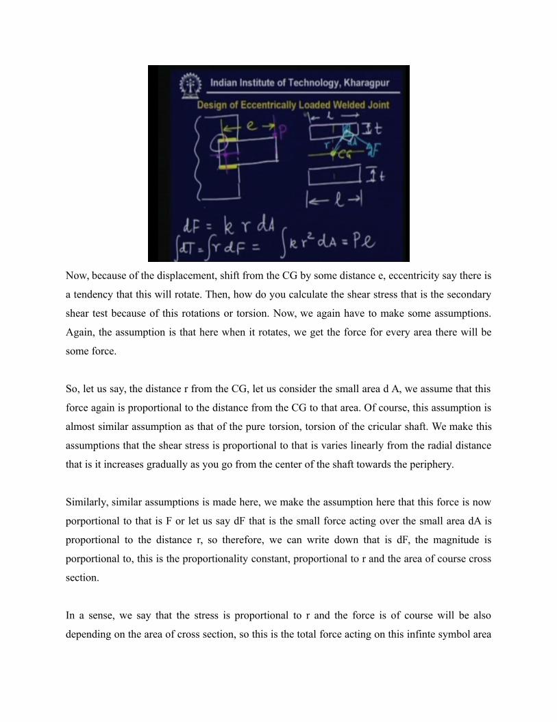
Now, because of the displacement, shift from the CG by some distance e, eccentricity say there is
a tendency that this will rotate. Then, how do you calculate the shear stress that is the secondary
shear test because of this rotations or torsion. Now, we again have to make some assumptions.
Again, the assumption is that here when it rotates, we get the force for every area there will be
some force.
So, let us say, the distance r from the CG, let us consider the small area d A, we assume that this
force again is proportional to the distance from the CG to that area. Of course, this assumption is
almost similar assumption as that of the pure torsion, torsion of the cricular shaft. We make this
assumptions that the shear stress is proportional to that is varies linearly from the radial distance
that is it increases gradually as you go from the center of the shaft towards the periphery.
Similarly, similar assumptions is made here, we make the assumption here that this force is now
porportional to that is F or let us say dF that is the small force acting over the small area dA is
proportional to the distance r, so therefore, we can write down that is dF, the magnitude is
porportional to, this is the proportionality constant, proportional to r and the area of course cross
section.
In a sense, we say that the stress is proportional to r and the force is of course will be also
depending on the area of cross section, so this is the total force acting on this infinte symbol area
dA. So, therefore the net torque will be = T, which is = dT will be = r times dF, the direction is
again important, direction is such that it tries to rotate, so therefore this direction of this force is
perpendicular.
So, this line the direction of this force d F is perpendicular to this line, the vector joining CG to
that infinite symbol area. So, therefore total torque will be = r times dF, so this is the torque over
this infinite symbol area. Hence, the total torque will be = the integral of this and that could be
written as k r square times dA and this is over the entire area. Now, this is again if you calculate
it, then this will be = the external torque this is pe.
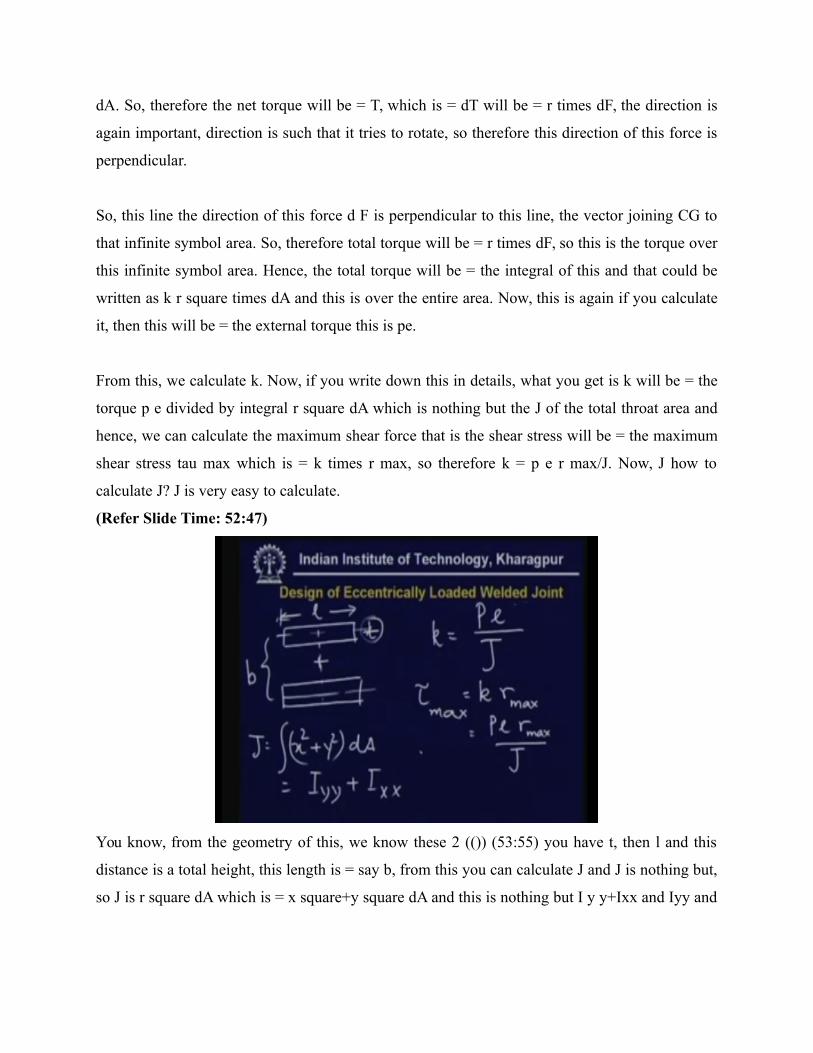
From this, we calculate k. Now, if you write down this in details, what you get is k will be = the
torque p e divided by integral r square dA which is nothing but the J of the total throat area and
hence, we can calculate the maximum shear force that is the shear stress will be = the maximum
shear stress tau max which is = k times r max, so therefore k = p e r max/J. Now, J how to
calculate J? J is very easy to calculate.
(Refer Slide Time: 52:47)
You know, from the geometry of this, we know these 2 (()) (53:55) you have t, then l and this
distance is a total height, this length is = say b, from this you can calculate J and J is nothing but,
so J is r square dA which is = x square+y square dA and this is nothing but I y y+Ixx and Iyy and
Ixx the second moment of area of this rectangles are easily known. remember t is taken to a very
very small compare to the other dimensions.
So, therefore the higher attempts containing t or sometimes neglected and in the book, what you
get there are some tables which are available, which contains the value of J for unit thickness that
is we consider the t to be unity, but of course, this unity is again very small thing, so therefore we
neglect when we have the higher attempts and what you get the value for unit t. whatever, then if
you have this relationship, what you have to do is, just take this data and multiply by the throat
length, which is =root 2, h/root 2, h is the height of the fillet weld.
So, if you do that then you get J, then tau max will be = p e r max divided by J what you have
now is that, you have tau max, the direction of the force, you cannot add vectorially through
stresses, but you can add vectorially these forces, so what you can do over a small cross sectional
area, you can calculate F that is the force, dF due to the load the direct shear stress and the shear
stress due to the torsions.
And then again you add vectorially and find out the maximum shear stress and using the
maximum shear stress theory, you can find out at the different design parameters, so this is
roughly the way how to calculate the welded joints when there are eccentric loading. So, let us
recapitulate what we have learnt, we have learnt how to calculate the design, how to calculate the
strength of joints with eccentrically loading for riveted joints, here mainly the shear stress is
exist.
In the bolted joints, there may be cases where the only the tensile force appears or there may be
cases where both shear force and tensile force appears and in eccentrically loaded welded joints,
there is the case where the shear stress will appear, sometimes we can have tensile force, but we
are not going to discuss them. So, this is all about the eccentrically loaded joints. Thank you very
much.
Let us begin the lectures on machine design part I, this is lecture number 26 and the topic is
design of joints with variable loading. In the last few lectures, we have learnt how to design the
joint for strength, for various static loadings. Now, in the last class, we have learnt how to design
the joint for eccentric loading and in this class, we are going to study for the variable loading.
Now, variable loading is very important for any machine components.
In structural joints, normally the loading is static, but in machine component there will be
invariables and movable parts and because of this movement, there will be the forces which are
normally fluctuating in nature. So, these are to be taken care of while designing.