Embed Size (px)
Citation preview
DESY July 2, 2003 J. Cvach: APD & preamp 1
Checks of APD matrix & Prague 16ch. preamplifier
1. Cross talk between pixels2. Homogeneity of response from pixels3. Minical beam tests
APD: Hamamatsu matrix S8550 with 32 pixels
Preampli: 16 channel voltage preamp on PCBLight: pulsed LEDs at 1 kHzSignal: triggered at 350 ns gate sent to ADC
Done mainly by S. Němeček, J. Zálešák, I. Polák, Institute of Physics AS CR, Prague
DESY July 2, 2003 J. Cvach: APD & preamp 2
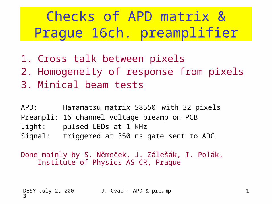
Measurement set-up
APD matrix
pixels withsame bias V
LED
3 LED (A, C, D)
LED A, D – 3 fibresLED C – 1 fibre
Pixels with light
Pixels w/o light
LED pulses from preamp
DESY July 2, 2003 J. Cvach: APD & preamp 3
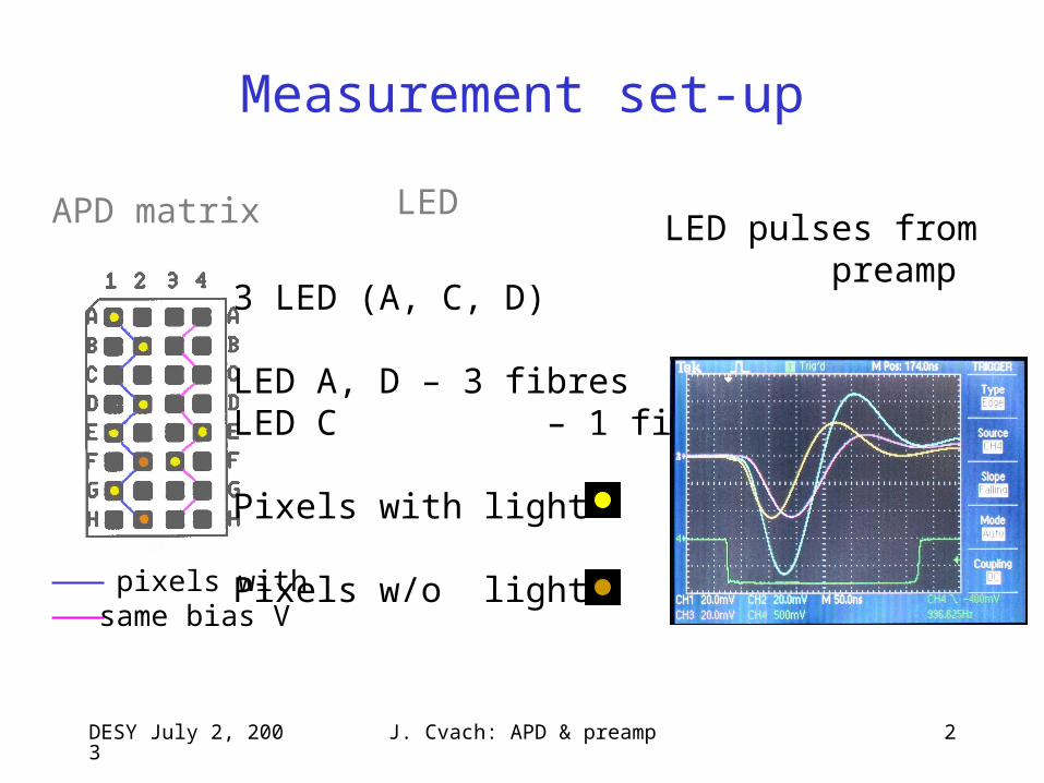
Cross talk for pixels F3, G1
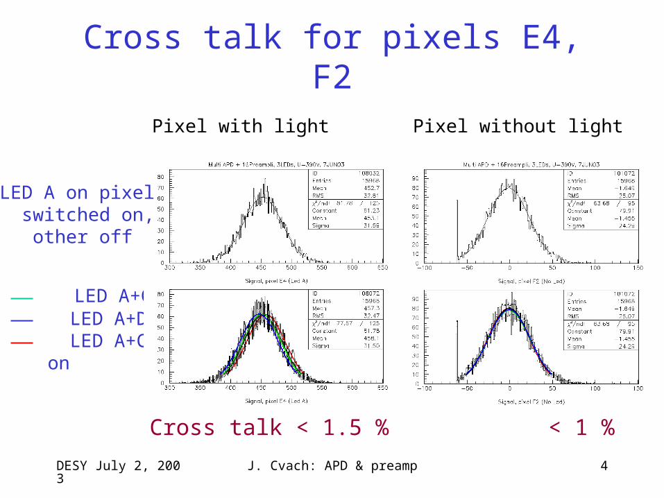
LED C on pixel switched on, other off
LED C+D LED C+A LED C+A+D
on
Cross talk between pixels < 1 %
DESY July 2, 2003 J. Cvach: APD & preamp 4
Cross talk for pixels E4, F2
LED A+C LED A+D LED A+C+D
on
LED A on pixel switched on, other off
Pixel with light Pixel without light
Cross talk < 1.5 % < 1 %
DESY July 2, 2003 J. Cvach: APD & preamp 5
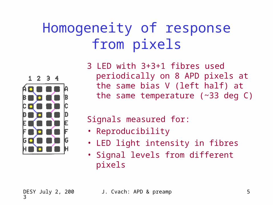
Homogeneity of response from pixels
3 LED with 3+3+1 fibres used periodically on 8 APD pixels at the same bias V (left half) at the same temperature (~33 deg C)
Signals measured for:
• Reproducibility
• LED light intensity in fibres
• Signal levels from different pixels
DESY July 2, 2003 J. Cvach: APD & preamp 6
Results
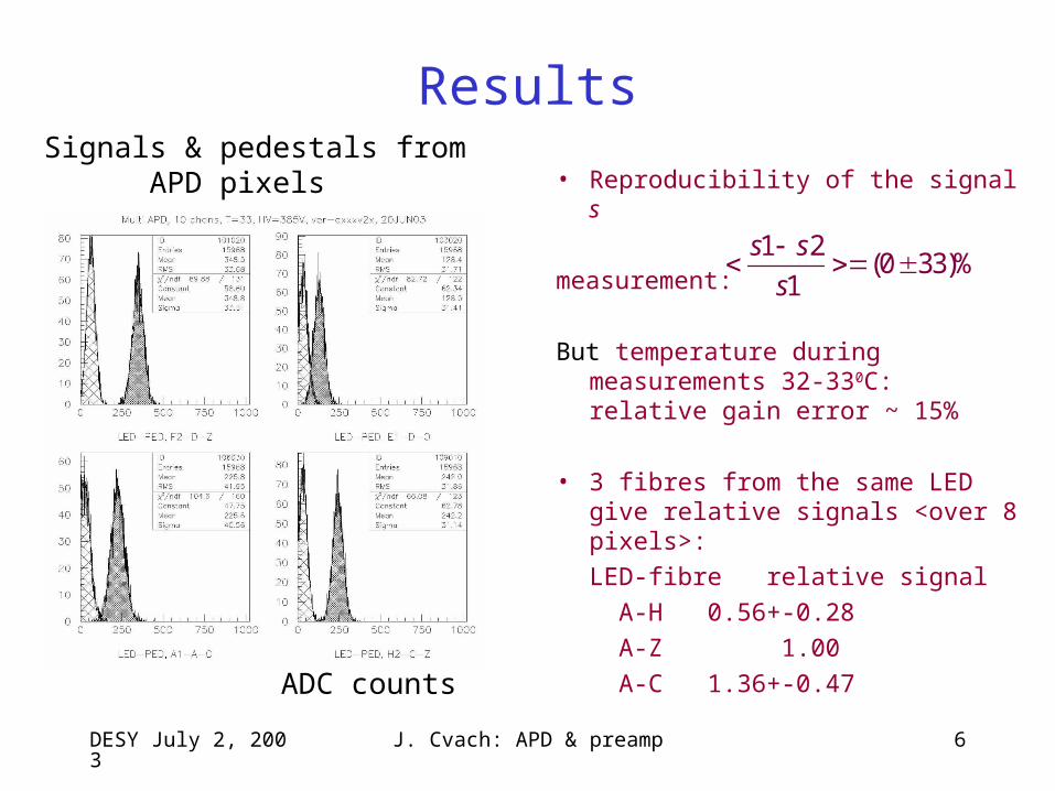
• Reproducibility of the signal s
measurement:
But temperature during measurements 32-330C: relative gain error ~ 15%
• 3 fibres from the same LED give relative signals <over 8 pixels>:
LED-fibre relative signal
A-H 0.56+-0.28
A-Z 1.00
A-C 1.36+-0.47
1 2(0 33)%
1
s s
s
Signals & pedestals from APD pixels
ADC counts

DESY July 2, 2003 J. Cvach: APD & preamp 7
Our plans for beam tests
• APD – single channel (and matrix S8550) with• Prague 16 channel preamp board and• new board with Orsay 18 ch. preamp chip
(PCB design done by Milan Janata in Prague)• Backup with 16 channel PMTs (SV + JW)
we plan to be at DESY – weeks 32-34 (August)
good news – 20 single channel APDs delivered last Friday in customs in Prague – available for tests this week ??
DESY July 2, 2003 J. Cvach: APD & preamp 8
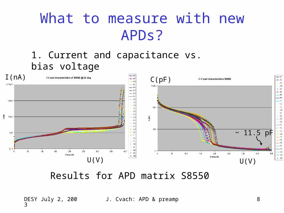
What to measure with new APDs?
U(V)
I(nA)
U(V)
C(pF)
~ 11.5 pF
1. Current and capacitance vs. bias voltage
Results for APD matrix S8550
DESY July 2, 2003 J. Cvach: APD & preamp 9
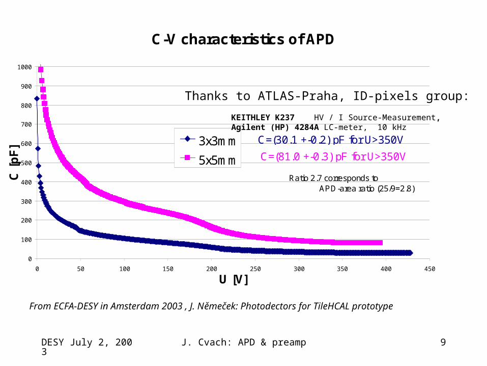
C-V characteristics of APD
0
100
200
300
400
500
600
700
800
900
1000
0 50 100 150 200 250 300 350 400 450
U [V]
C [
pF
] 3x3mm
5x5mm C=(81.0 +-0.3) pF for U>350V
C=(30.1 +-0.2) pF for U>350V
Ratio 2.7 corresponds to APD-area ratio (25/9=2.8)
Thanks to ATLAS-Praha, ID-pixels group:
KEITHLEY K237 HV / I Source-Measurement, Agilent (HP) 4284A LC-meter, 10 kHz
From ECFA-DESY in Amsterdam 2003 , J. Němeček: Photodectors for TileHCAL prototype
DESY July 2, 2003 J. Cvach: APD & preamp 10
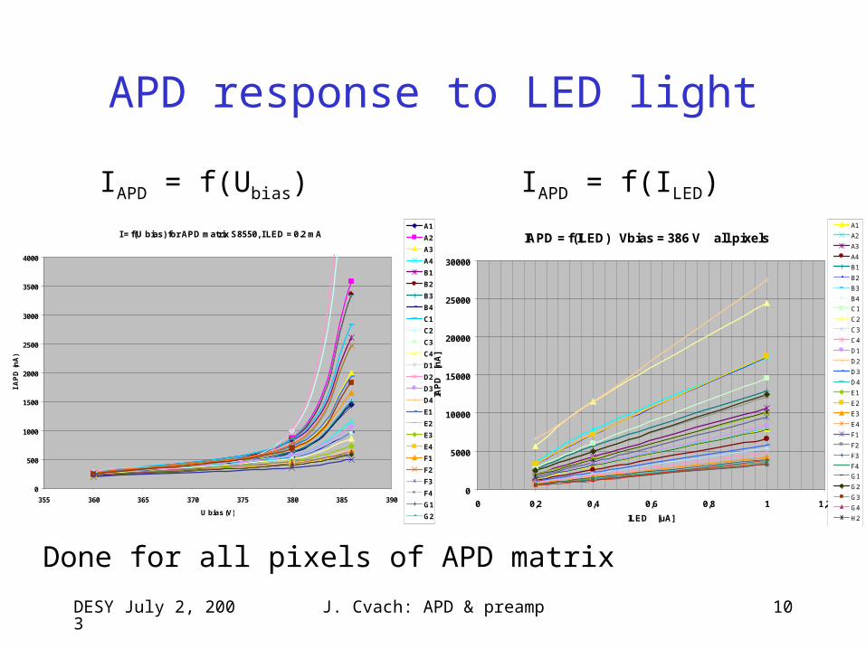
APD response to LED light
I = f(U bias) for APD matrix S8550, I LED = 0.2 mA
0
500
1000
1500
2000
2500
3000
3500
4000
355 360 365 370 375 380 385 390
U bias (V)
I A
PD
(n
A)
A1
A2
A3
A4
B1
B2
B3
B4
C1
C2
C3
C4
D1
D2
D3
D4
E1
E2
E3
E4
F1
F2
F3
F4
G1
G2
G3
G4
IAPD = f(Ubias)
IAPD = f(ILED) Vbias = 386 V all pixels
0
5000
10000
15000
20000
25000
30000
0 0,2 0,4 0,6 0,8 1 1,2
ILED [uA]
IAP
D
[nA
]
A1
A2
A3
A4
B1
B2
B3
B4
C1
C2
C3
C4
D1
D2
D3
D4
E1
E2
E3
E4
F1
F2
F3
F4
G1
G2
G3
G4
H2
H3
H4
IAPD = f(ILED)
Done for all pixels of APD matrix
DESY July 2, 2003 J. Cvach: APD & preamp 11
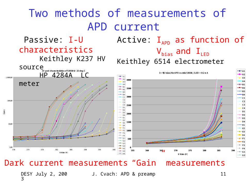
Two methods of measurements of APD current
I = f(U bias) for APD matrix S8550, I LED = 0.2 mA
0
500
1000
1500
2000
2500
3000
3500
4000
355 360 365 370 375 380 385 390
U bias (V)
I A
PD
(n
A)
A1
A2
A3
A4
B1
B2
B3
B4
C1
C2
C3
C4
D1
D2
D3
D4
E1
E2
E3
E4
F1
F2
F3
F4
G1
G2
G3
G4
I-V pad characteristics of S8550 @ 22 deg C
1,00
10,00
100,00
1 000,00
370 374 378 382 386 390 394 398
U bias (V)
I (n
A)
A1
A2
A3
A4
B1
B2
B3
B4
C1
C2
C3
C4
D1
D2
D3
D4
E1
E2
E3
E4
F1
F2
F3
F4
G1
G2
G3
G4
H2
H3
H4
Passive: I-U characteristics Keithley K237 HV source HP 4284A LC meter
Active: IAPD as function of Vbias and ILED Keithley 6514 electrometer
Dark current measurements “Gain” measurements
DESY July 2, 2003 J. Cvach: APD & preamp 12
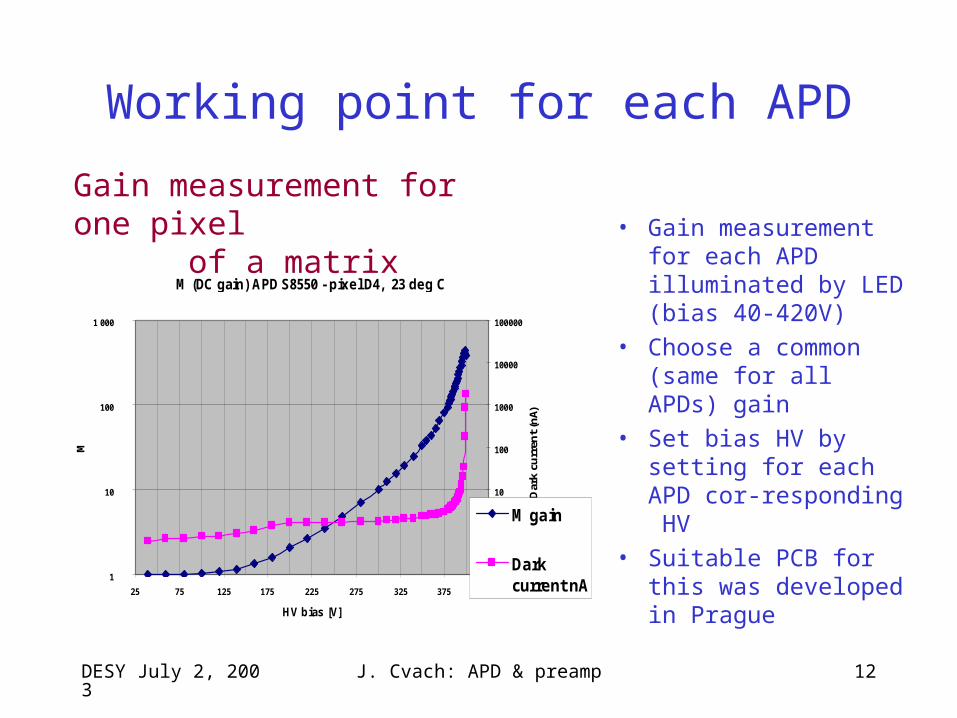
Working point for each APD
M (DC gain) APD S8550 - pixel D4, 23 deg C
1
10
100
1 000
25 75 125 175 225 275 325 375 425
HV bias [V]
M
0,1
1
10
100
1000
10000
100000
Dar
k cu
rren
t (n
A)
M gain
Darkcurrent nA
• Gain measurement for each APD illuminated by LED (bias 40-420V)
• Choose a common (same for all APDs) gain
• Set bias HV by setting for each APD cor-responding HV
• Suitable PCB for this was developed in Prague
Gain measurement for one pixel of a matrix
DESY July 2, 2003 J. Cvach: APD & preamp 13
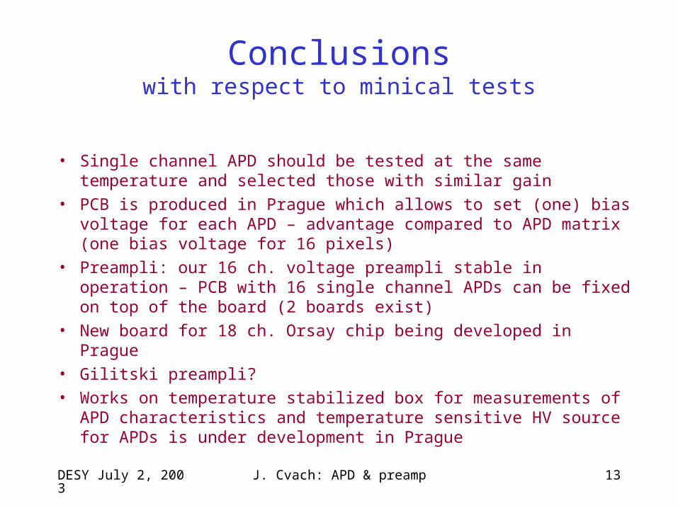
Conclusionswith respect to minical tests
• Single channel APD should be tested at the same temperature and selected those with similar gain
• PCB is produced in Prague which allows to set (one) bias voltage for each APD – advantage compared to APD matrix (one bias voltage for 16 pixels)
• Preampli: our 16 ch. voltage preampli stable in operation – PCB with 16 single channel APDs can be fixed on top of the board (2 boards exist)
• New board for 18 ch. Orsay chip being developed in Prague
• Gilitski preampli?
• Works on temperature stabilized box for measurements of APD characteristics and temperature sensitive HV source for APDs is under development in Prague