Embed Size (px)
Citation preview

Detailed design 6

6 Detailed design 43
6 Detailed design
6.1 INTRODUCTIONOnce all preliminary investigations have been made and a suitable site has been found, the next step is to carry out a detailed survey of the valley and reservoir area to allow more accurate estimates of quantities and to provide the necessary data for design work to be undertaken. The aim of such a survey is to present, on paper, a contour map of the reservoir up to and exceeding the maximum flood level, and to provide details for the location of the embankment, spillway and outlet works. From the contour map, the capacity of the reservoir can be assessed for varying dam heights. A depth-capacity curve can then be drawn up to provide a quick and easy method for the dam designer to choose the optimum full supply level. A simplified example of a depth-capacity curve is shown in Figure 7. Often the depth-surface area curve (usually with a reversed scale) is added to these graphs.
6.2 CONTOUR SURVEY On very large sites it may be possible to draw up a contour map – at an interval suitable for the design (normally 0.5 m is satisfactory for small dams) – from aerial photography or satellite imagery using specialized stereo plotting and digitization techniques that, although expensive, may pay for themselves in the time saved in avoiding groundwork. However, if this is not possible, as is usual on smaller sites, one of three methods of ground survey14 below will be necessary:
14 High levels of accuracy are not required at this stage considering that elevations will later be affected by site stripping pre-construction.
FULL SUPPLY LEVEL
5.0
4.0
3.0
2.0
1.0
DE
PTH
(m
)
CAPACITY (m3 x 103)
02 4 6 8 10 12 14 16 18 20 22 24 26 28 30
Figure 7 - Typical depth capacity curve

Manual on small earth dams44
1. Grid survey This is a simple and straightforward but time-consuming method. Also it may not be possible if the area is heavily vegetated and/or physically inaccessible.
2. Cross-sectionsCross-section surveys are taken along various lines within the river valley(s) from benchmarks previously established. Levels are observed at set intervals and outstanding features (changes of slope in particular) are also noted.
3. Spot heightsThis is especially suited to larger areas. A circuit of benchmarks is established and spot height observations with bearing, distance and elevation are made from each station. For smaller dams, and if a theodolite or electronic instrument is used, it may be possible to take all the readings from one station. Alternatively, reason-ably accurate GPS surveys can be used to establish a network of elevation readings across the site.
6.3 REVISED CAPACITY From the contour survey, an estimation of the surface area of the reservoir can be made for the full supply and other levels. The approximate capacity of the reservoir can be assessed from Table 2 below. For example, to find the capacity of a reservoir with a maximum depth of 3.25 m and a surface water area of 32.7 ha, the following steps, extrapolating where needed, are made:
(i) 30 ha at 3.25 = 325 000 m3
(ii) 2 ha at 3.25 = 21 666 m3
(iii) 0.7 ha at 3.25 = 7 583 m3 Total capacity = 354 249 m3
A quick reference check using the formula:
where H’ is the maximum depth in m. (3.25 m) and A’ is the surface area in m2 (327 000 m2) results in a figure of 354 250 m3 and closely correlates with that already determined from Table 2.
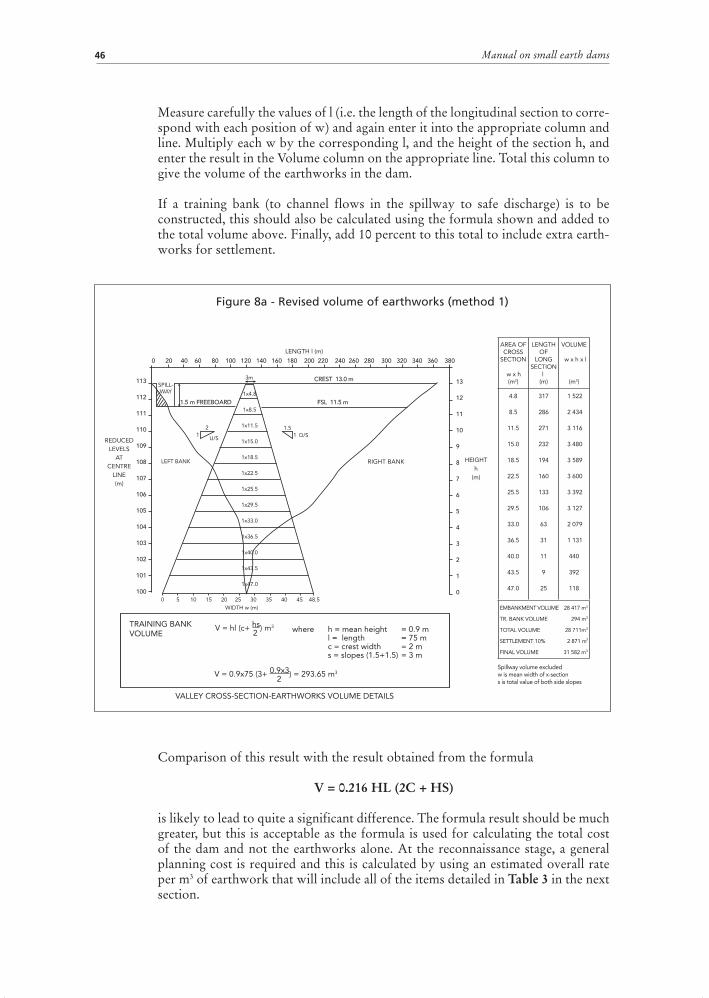
6.4 REVISED VOLUME OF EARTHWORKSMethod 1 Although this method is not as accurate as Method 2 it is useful for the relatively rapid calculation of volumes of a number of proposed dams for comparison purposes. It is reasonably accurate in its estimates of quantities and subsequent costing of the proposed works. The embankment volumes are calculated, as in the example shown in Figure 8a, as follows:
Fill in the reduced level column on the left-hand side of the sectional paper, starting with the settled crest level on the top line. It is advisable, for ease of working, to consistently use a reference reduced level of 100 (largely to avoid having negative
Q = H’ A’3

6 Detailed design 45
values when referring to the crest height and to make any calculations above or below this reference level easy to work out) either for the highest or for the lowest point of the proposed embankment.
Draw in the longitudinal section by accurately plotting ground levels against distance (on the upper scale marked crest length) and join these points with lines to show the cross-section profile of the valley. The spillway is not included.
Draw the cross-section of the proposed dam at its maximum height (i.e. above stream bed) after settlement, starting with the upstream toe on the left at zero (using the horizontal scale at the bottom and marked base width), working up to the crest, along and down to the downstream toe. This plotting must be carried out accurately as scaled dimensions are to be used in the calculations. Calculate, and check by measurement, values of w (i.e. the mean width of each 0.5 m or 1 m cross section) commencing with the crest section and enter it in the appropriate column and line.
Table 2 Approximate reservoir capacities (in m3)
Reservoir area (ha)
Depth of water at deepest point
1 m 1.5 m 2 m 2.5 m 3 m 3.5 m 4 m1 3 333 5 000 6 666 8 333 10 000 11 666 13 3332 6 666 10 000 13 333 16 666 20 000 23 333 26 6663 10 000 15 000 20 000 25 000 30 000 35 000 40 0004 13 333 20 000 26 666 33 333 40 000 46 666 53 3335 16 666 25 000 33 333 41 666 50 000 58 333 66 6666 20 000 30 000 40 000 50 000 60 000 70 000 80 0007 23 333 35 000 46 666 58 333 70 000 81 666 93 3338 26 666 40 000 53 333 66 666 80 000 93 333 106 6669 30 000 45 000 60 000 75 000 90 000 105 000 120 00010 33 333 50 000 66 666 83 333 100 000 116 666 133 33320 66 666 100 000 133 333 166 666 200 000 233 333 266 66630 100 000 150 000 200 000 250 000 300 000 350 000 400 00040 133 333 200 000 266 666 333 333 400 000 466 666 533 33350 166 666 250 000 333 333 416 666 500 000 583 333 666 666
Depth of water at deepest point4.5 m 4.75 m 5 m 5.25 m 5.5 m 5.75 m 6 m
1 15 000 15 833 16 666 17 500 18 333 19 166 20 0002 30 000 31 666 33 333 35 000 36 666 38 333 40 0003 45 000 47 500 50 000 52 500 55 000 57 500 60 0004 60 000 63 333 66 666 70 000 73 333 76 666 80 0005 75 000 79 166 83 333 87 500 91 666 95 333 100 0006 90 000 95 000 100 000 105 000 110 000 115 000 120 0007 105 000 110 833 116 666 122 500 128 333 134 166 140 0008 120 000 126 666 133 333 140 000 146 666 153 333 160 0009 135 000 142 500 150 000 157 500 165 000 172 500 180 00010 150 000 158 333 166 666 175 000 183 333 191 666 200 00020 300 000 316 666 333 333 350 000 366 666 383 333 400 00030 450 000 475 000 500 000 525 000 550 000 575 000 600 00040 600 000 633 333 666 666 700 000 733 333 766 666 800 00050 750 000 791 666 833 333 875 000 916 666 958 333 1000 000
Manual on small earth dams46
Measure carefully the values of l (i.e. the length of the longitudinal section to corre-spond with each position of w) and again enter it into the appropriate column and line. Multiply each w by the corresponding l, and the height of the section h, and enter the result in the Volume column on the appropriate line. Total this column to give the volume of the earthworks in the dam.
If a training bank (to channel flows in the spillway to safe discharge) is to be constructed, this should also be calculated using the formula shown and added to the total volume above. Finally, add 10 percent to this total to include extra earth-works for settlement.
Comparison of this result with the result obtained from the formula
V = 0.216 HL (2C + HS)
is likely to lead to quite a significant difference. The formula result should be much greater, but this is acceptable as the formula is used for calculating the total cost of the dam and not the earthworks alone. At the reconnaissance stage, a general planning cost is required and this is calculated by using an estimated overall rate per m3 of earthwork that will include all of the items detailed in Table 3 in the next section.
113
112
111
110
109
108
107
106
105
104
103
102
101
100
13
12
11
10
9
8
7
6
5
4
3
2
1
0
0 20 40 60 80 100 120 140 160 180 200 220 240 260 280 300 320 340 360 380
HEIGHTh
(m)
LENGTH l (m)
SPILL-WAY
2 1.51 1
U/S D/S
RIGHT BANK
TRAINING BANKVOLUME
LEFT BANK
1x4.8
1x8.5
1x11.5
1x15.0
1x18.5
1x22.5
1x25.5
1x29.5
1x33.0
1x36.5
1x40.0
1x43.5
1x47.0
REDUCEDLEVELS
ATCENTRE
LINE(m)
0 5 10 15 20 25 30 35 40 45 48.5WIDTH w (m)
V = hl (c+ hs) m3
2
V = 0.9x75 (3+ 0.9x3) = 293.65 m3
2
where h = mean height = 0.9 m l = length = 75 m c = crest width = 2 m s = slopes (1.5+1.5) = 3 m
VALLEY CROSS-SECTION-EARTHWORKS VOLUME DETAILS
AREA OF CROSS
SECTION
w x h(m2)
LENGTH OF
LONG SECTION
l(m)
VOLUME
w x h x l
(m3)
4.8
8.5
11.5
15.0
18.5
22.5
25.5
29.5
33.0
36.5
40.0
43.5
47.0
317
286
271
232
194
160
133
106
63
31
11
9
25
1 522
2 434
3 116
3 480
3 589
3 600
3 392
3 127
2 079
1 131
440
392
118
EMBANKMENT VOLUME 28 417 m3
TR. BANK VOLUME 294 m3
TOTAL VOLUME 28 711m3
SETTLEMENT 10% 2 871 m3
FINAL VOLUME 31 582 m3
Spillway volume excludedw is mean width of x-sections is total value of both side slopes
1.5 m FREEBOARD
CREST 13.0 m
FSL 11.5 m
3m
Figure 8a - Revised volume of earthworks (method 1)

6 Detailed design 47
Method 2 Method 2 (see Figure 8b) is much the same as Method 1 except that the cross-sectional area is calculated more accurately. The cross-section is squared off as illustrated and each rectangle has its respective area calculated in a straightforward manner (i.e. length x breadth). The remaining triangular pieces which flank each rectangle have constant areas that are calculated as follows:
� upstream slope 1:2, height of section 1 m, area of upstream triangle= (2/2) x 1 = 1 m2� downstream slope 1:1.75, height of section 1 m, area of downstream triangle
= (1.75/2) x 1 = 0.875 m2 Therefore, each cross-sectional area can now be estimated relatively quickly and the method of assessing volumes proceeds as in Method 1.
Finished versions of the method can then be presented on design drawings with allowances for over-excavation, training walls and settlement and without the calculations.
6.5 DESIGN DRAWINGSIt is important to provide comprehensive, useful design drawings for implementing the works and for eventual tendering and award of contract. Standardizing these drawings is equally important and being able to present one sheet with sufficient data on it to explain the design, list the main quantities and provide details of the
113
112
111
110
109
108
107
106
105
104
103
102
101
100
13
12
11
10
9
8
7
6
5
4
3
2
1
0
0 20 40 60 80 100 120 140 160 180 200 220 240 260 280 300 320 340 360 380
HEIGHT(m)‘h’
LENGTH l (m)
SPILL-WAY
2 1.51 1
U/S D/S
RIGHT BANKLEFT BANK
REDUCEDLEVELS
ATCENTRE
LINE(m)
0 5 10 15 20 25 30 35 40 45 48.5WIDTH w (m)
1 m2
1.0 m2
1.0 m2
0.75 m2
0.75m2
0.75 m2
3.0m2
AREA OF CROSS
SECTION
w x h(m2)
LENGTH OF
LONG SECTION
l(m)
VOLUME
w x h x l
(m3)
4.75
8.75
11.75
15.25
18.75
22.75
25.75
29.75
32.75
36.75
39.75
43.25
46.75
317
286
271
232
194
160
133
106
63
31
11
9
25
1 506
2 502
3 184
3 538
3 637
3 640
3 425
3 153
2 063
1 139
437
389
117
EMBAKMENT VOLUME 28 730 m3
TR. BANK VOLUME 294 m3
TOTAL VOLUME 29 024 m3
SETTLEMENT 10% 2 902 m3
FINAL VOLUME 31 926 m3
Spillway volume excludedw is mean width of x-sections is total value of both side slopes
7 m2
10 m2
13.5 m2
17 m2
20.5 m2
24 m2
28 m2
31 m2
35 m2
38 m2
41.5 m2
45 m2
1.5 m FREEBOARD
CREST 13 m
FSL 11.5 m
3m
Figure 8b - Revised volume of earthworks (method 2)

Manual on small earth dams48
location is essential. Further drawings for more specialized aspects of the works can also be provided.
Standard drawings in A3 format are provided in Annex 4 with examples of the more specialized drawings required. Regardless of the design and its complexity or otherwise, all drawings should be of a high standard and be presented on quality paper as well as in electronic format.
6.6 ESTIMATED COST OF DAM CONSTRUCTION The costing of the dam can now go ahead, with estimates based on either costs for dams already constructed in the same locality or rates provided by local contractors and or government departments. A list of quantities following the guidelines given in Table 3 can then be drawn up.
Should the dam (or dams) design and costing be prepared for tender or contracting to the private sector it is important that the details on costing for Table 3 and any engineer’s estimates remain confidential and be used as a guide in evaluating any bids or other proposals from potential contractors to construct the dam(s). Annex 1 has more details on this.
6.7 OUTLET WORKS With any dam the major outlet work is the spillway, but other minor outlet structures may be required to release water for irrigation, trickle flows or other purposes.
6.7.1 The spillwayThe spillway is the most important outlet and has to be designed to accommodate the anticipated peak flood. It has to be a permanent structure that will not erode and is located at a level that allows for the required water depth and freeboard ascertained at the site selection and investigations stage.
Table 3 Quantities and costs of dam construction
Item Description Unit Quantity Rate Amount1 Site investigation Sum2 Engineer fees Sum3 Movement charge Sum4 Clearing site Hours5 Excavating cutoff/core m3
6 Backfilling m3
7 Embankment work m3
8 Training bank(s) m3
9 Spillway m3
10 Topsoil return m3
11 Trimming/tidying Hours12 Other …..
Subtotal
Contingencies @ x%
Total
6 Detailed design 49
Critical items are the entrance width ‘b’ (already discussed above and dependent on the peak flood), the outfall (dependent usually on ‘b’ – refer below) and the material the spillway will be constructed with and sited upon.
For grass spillways, the erosion hazard is an important consideration. Therefore, this type of spillway should be horizontal at its entrance, ideally with a concrete or masonry sill to level the entrance and control velocities and erosion. It can have a slight crossfall (but no more than 5o) across the spillway and must have a safe outfall to return floodwaters to the stream. Allowable flow velocities will depend upon depth of flow (and in turn affect the freeboard) and the floor material of the spillway.
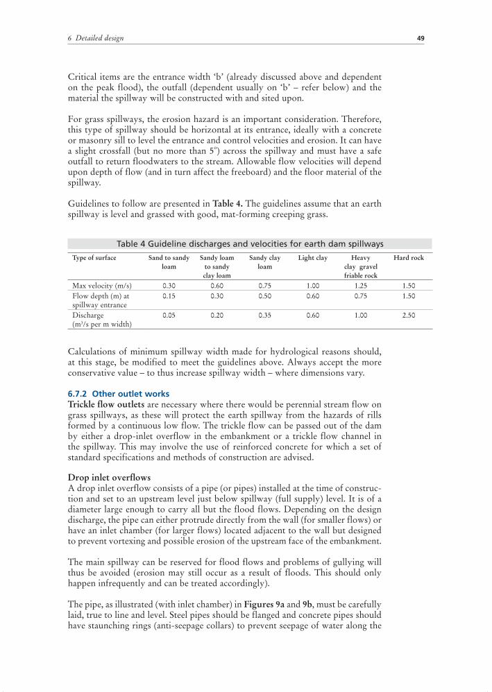
Guidelines to follow are presented in Table 4. The guidelines assume that an earth spillway is level and grassed with good, mat-forming creeping grass.
Calculations of minimum spillway width made for hydrological reasons should, at this stage, be modified to meet the guidelines above. Always accept the more conservative value – to thus increase spillway width – where dimensions vary.
6.7.2 Other outlet works Trickle flow outlets are necessary where there would be perennial stream flow on grass spillways, as these will protect the earth spillway from the hazards of rills formed by a continuous low flow. The trickle flow can be passed out of the dam by either a drop-inlet overflow in the embankment or a trickle flow channel in the spillway. This may involve the use of reinforced concrete for which a set of standard specifications and methods of construction are advised.
Drop inlet overflows A drop inlet overflow consists of a pipe (or pipes) installed at the time of construc-tion and set to an upstream level just below spillway (full supply) level. It is of a diameter large enough to carry all but the flood flows. Depending on the design discharge, the pipe can either protrude directly from the wall (for smaller flows) or have an inlet chamber (for larger flows) located adjacent to the wall but designed to prevent vortexing and possible erosion of the upstream face of the embankment.
The main spillway can be reserved for flood flows and problems of gullying will thus be avoided (erosion may still occur as a result of floods. This should only happen infrequently and can be treated accordingly).
The pipe, as illustrated (with inlet chamber) in Figures 9a and 9b, must be carefully laid, true to line and level. Steel pipes should be flanged and concrete pipes should have staunching rings (anti-seepage collars) to prevent seepage of water along the
Table 4 Guideline discharges and velocities for earth dam spillways
Type of surface Sand to sandy loam
Sandy loam to sandy clay loam
Sandy clay loam
Light clay Heavy clay gravel friable rock
Hard rock
Max velocity (m/s) 0.30 0.60 0.75 1.00 1.25 1.50Flow depth (m) at spillway entrance
0.15 0.30 0.50 0.60 0.75 1.50
Discharge (m3/s per m width)
0.05 0.20 0.35 0.60 1.00 2.50

Manual on small earth dams50
outside of the pipe. The pipe should be laid in a trench cut in original ground on the valley sides before the embankment is built. If stream flows are not known, the minimum diameters of pipe are as follows:
– 300 mm for very small catchments. – 375 mm for catchments up to 5 km2. – 450 to 550 mm for catchments between 5 and 8 km2 (i.e. ‘44 gallon’ drums in
concrete).
For known expected maximum stream flows the diameters of the pipe and its physical gradient can be selected from Tables 5a or 5b.
Figure 9a - Drop-inlet overflow
Figure 9b - Section of a drop-inlet overflow

6 Detailed design 51
Table 5a is based on a maximum flow velocity of 2 m/s or a maximum friction head loss of 2 m per 100 m of pipe. See Figures 9a and 9b for D1 and D2.
Trickle flow spillwaysWhere normal flows are small or a drop-inlet overflow was not installed at the time of construction, a trickle flow spillway can be constructed within the existing grass spillway(s). A well founded stone-pitched or brick-lined channel designed to carry average stream flow can avoid subsequent erosion of the main spillway. A concrete or masonry sill placed across the entrance and exit of the grassed spillway will also reduce risk of erosion as well as allowing for control of the full supply level in conjunction with a drop-inlet pipe. Maintenance (de-silting and repair works) may be required after major floods or at the end of each rainy season.
6.7.3 Training banks and spillway outfallWhether the spillway be grass, rock, drop-inlet, or trickle flow, an essential requirement will be a safe return to flow downstream of the embankment. For any spillway the avoidance of bends or constrictions to the channel must be adhered to.
Grass, and occasionally rock spillways, may require the construction of training banks (stone pitched if necessary) to guide the flood flows away from the steeper
Table 5b – Gradient chart for drop-inlet overflow pipes
Q (l/s)
Internal diameter of pipe (mm)75 100 125 150 225 300 375 400
Approximate gradient required (1: … ) 1.5369121520253040506075100150
32080
1 470370
901 210
300135
7550
800350200130
80
1 7501 130
700350280180
1 6001 300
830400325210
1 3001 070
690300170
2 3001 800
750450
Note: Pipes are assumed flowing full, under negligible water pressure and are constructed of concrete or similar.
Table 5a – Guide to minimum dimensions of drop-inlet chambers and pipes
Dimension D1 (mm) Dimension D2 (mm) Diameter D3 (mm) Capacity (litres/s)300 300 100 15500 300 150 30600 500 225 70
1 200 500 300 1252 000 1 000 375 2003 000 1 600 400 250

Manual on small earth dams52
slopes and the downstream toe of the dam. A maximum slope of about 5 percent for the return should be the goal and this should only be exceeded where rock is to be used for the return. The actual outfall should be designed to be non-erosive and, as a rule of thumb, the final width should be 1.5 to 2 times the entrance width ‘b’ thus reducing velocities of flow to manageable levels. Examples of training bank and outfall designs are provided in the sample layout drawings in Annex 4.
On rock spillways, downstream erosion that will not endanger the embankment or cause environmental problems and which will stop once the flow has eroded back to the rock, is permissible. For drop inlet overflows the construction of a channel of brick or stone from pipe outlet should be sufficient and this can then be led to a safe dissipation point downstream.
If farm machinery or other vehicles are expected to use the embankment and spillway as a road, the side slopes of the spillway should not exceed 25 percent and some protection (i.e. stone or concrete crossings) from erosion by traffic should be constructed at the time of building the dam.
6.7.4 Other outletsWhere the expected flows are sufficiently small, pipes leading through the embank-ment high up on one bank at full supply level may be used and will prove cheaper than a box inlet type overflow. Care must be exercised in leading the flow back to the streambed and usually a stone pitched, brick or concrete lined channel is required. Outlet pipes are often required where a regulated flow of water is needed and these will be of steel or concrete with a control valve installed. The best option is to lay the piping beneath the embankment (even if high up on the bank) at the time of construction and it is important to ensure good rock or compacted soil foundation along its entire length. The trench should be cut to size, (i.e. as narrow as possible), with provision for seepage collars or flanges every 4-6 m and the pipe laid on a bed of concrete and then covered by more concrete.
If the dam is already constructed and an outlet pipe is required, excavation into the embankment is not recommended as this would create an area of weakness in what is meant to be a unified structure. The alternatives are either to pump from the upstream side over the embankment or to construct a siphon.
The pump(s) could be located on a raft with a flexible connection to a fixed pipe on the dam, or be positioned on a ramp that will allow them to follow water levels as they rise and fall to avoid too high suction lifts occurring (i.e. more than 3-5 m).
Siphons require careful construction to ensure all joints and valves are airtight and, as insurance, some means of priming at the highest point may be incorporated in the pipeline. With a siphon it is essential that the outlet be located at a level below that of the inlet when the water level in the reservoir is at its lowest. Siphoning water over an elevation of more than 5 m is not advisable and it may be necessary to minimize the elevation difference by burying the pipe into the top portion of the embankment.
6.8 THE EMBANKMENT The embankment is the principal part of the dam and certain guidelines in design and construction must be followed: the side slopes must not be steeper than 1:2 on the upstream and 1:1.75 on the downstream sides. Where embankments are made of poor materials, or are likely to suffer erosion from cattle trampling or

6 Detailed design 53
wave action, the slopes should be made flatter to suit the circumstances involved. Anthills and solid rock outcrops should be avoided unless there is no alternative. Anthills should be completely excavated and the hole filled in, preferably with soil, or, as a last resort, with treated ant heap material in well compacted thin layers. Rock outcrops will require scraping down and key walls built into the embank-ment or core.
6.9 FREEBOARDFreeboard for small dams should never be less than 0.5 m with 0.75 m to 1.0 m preferred. Where wave action is likely, additional freeboard may be required. This can be estimated using the following formula:
Freeboard height, H’’ (in m) = 0.014 (F)0.5
where H’’ is the freeboard height and F is the fetch which is the longest distance, in km, across the storage area (usually measured in a straight line from the centre line of the proposed embankment to the tailwater area of the proposed reservoir). The overall freeboard height can then be calculated taking into account the wet freeboard, H’’, (as estimated with the formula above) required to counteract wave action and the dry freeboard (estimated by the engineer) for safety and other factors. The total freeboard is effectively the design depth for the spillway (at its entrance).
6.10 CORE DEPTH AND THICKNESSCores and cutoffs are expensive items in construction and should be designed to the minimum required according to the FSL, the method of construction and taking into account the comments below. The core will usually comprise the centre of the embankment (refer to zoned dams above) and be designed to reduce seepage to manageable levels.
For designing small dams, as the cutoff can be excavated by hand or small machin-ery, it need not exceed 2 m wide. For larger dams, cutoffs can be excavated by bulldozer or scraper and then will require a width, usually 4 m, that permits access.
Depths of cutoff should be to good foundation (solid rock or impermeable subsoil layer) or to at least 0.75 times the height of the embankment. When using the latter guideline, if poor material is encountered at the depth for finishing the excavation, the cutoff should be continued until good foundation is encountered. It is very difficult to rectify cutoff problems once the dam is completed and the reservoir full of water so care must be taken in constructing this vital part of the dam and costs should not be compromised. To further ensure that the cutoff is constructed properly, and especially for trenches being excavated by contractors, the supervis-ing engineer should insist that the finished trench is inspected before backfilling commences.
Excavation of any trench requires safety factors to be considered and, for deep trenches, benched or sloping sides or other measures may be required to reduce the possibilities of the sides collapsing. Sloping or benched sides also permit easier compaction and improves the bond between the backfill and the existing ground.

Manual on small earth dams54
6.11 CREST WIDTHThe crest width of an embankment is selected taking into account the size of the dam, the catchment characteristics and topography and whether road or other access will be required across the embankment. In all cases, the embankment crest width should be designed to allow the safe passage of plant and equipment to be used in the dam construction and should be no less than 2 m wide.
Alternatively, and most appropriate to small dams exceeding 5 m in height, a standard crest width of 3 m can be adopted or the formula below can be used:
Cw (in m) = 0.4H + 1
where Cw is the crest width and H is the maximum height of the dam in metres.
Always adopt the widest crest width possible (and flatter embankment slopes) where foundations or construction materials are suspect.
To reduce erosion, all crests should be given a 2.5 percent crossfall to drain rainwa-ter to the reservoir via the upstream slope of the embankment.
6.12 SETTLEMENT ALLOWANCEThe embankment will always settle a little after construction and the finished crest should be given a settlement allowance that raises it above its design height at the mid-point by between 5 percent and 10 percent and tapering off to the spillway and valley sides.
6.13 STONE PITCHING AND TRAINING BANKSStone pitching is usually not necessary, as a good grass cover is normally sufficient to protect the embankment here.
However, occasionally training banks may require stone pitching protection, depending on the climatic regime and likely flood flows. The training banks should be long enough to divert water safely away from the downstream toe of the dam. They should have the same proportions and crest level as the main embankment. Where natural spillways are to be used, the training bank material must be imported from borrow areas as excavation on the site of the natural spillway is not desirable. Similarly, the traversing of plant and vehicles over a natural spillway could lead to problems later in establishing a good grass cover on partially compacted soils and erosion in places where wheel tracks have been made.
6.14 SEEPAGE Seepage is always a potential problem that should be considered at this stage and the designer-builder will have to bear in mind the permeability of the fill materials and of the foundation, the position and flow of groundwater at the site, the type and design of any core or below ground cutoff within the embankment, and the use of drainage devices to collect and safely channel seepage water in the downstream section of the embankment. All earth dams will have some seepage and it is unre-alistic not to expect this. If seepage is considered as a potential problem, counter-measures – such as filters, drains, clay blankets and flatter side slopes – introduced at the design stage can reduce any risks to a minimum.

6 Detailed design 55
6.15 FILTERS AND DRAINSFilters are expensive and are not normally required for smaller dams.
The aim of all seepage ‘filter’ drains is to lower the phreatic surface (the ‘seepage line’) within the embankment to prevent water from emerging from the down-stream slope where erosive and absorptive flows could cause slumping of the material and endanger the whole structure.
Trenches dug into the subsoil beneath the downstream face and toe, at the time of construction, and filled with rock and gravel (the latter helping to limit the movement of finer embankment material into the drains) and continued to a collec-tor drain network at least 3-5 m below the toe line, can safely bring seepage lines down to allow flow out from beneath the embankment.
The configuration of the filter zones, however, will depend upon the type of embankment:��In a modified homogenous dam, the filter is generally placed as a blanket15
of sand and fine gravel on the downstream foundation area, extending from the cutoff/core trench boundary to the edge of the downstream toe and then taken to safe discharge by the toe drains.
��In a zoned dam, the filter is placed between the core and the downstream shell zone. A longitudinal ‘chimney’ drain of gravel material that collects the intercepted seepage flow and carries it to the base of the chimney and, via one or more transverse drains, conveys the water to the toe drains outside the embankment.
Such drains are essential when seepage risks are considered high – for example, a downstream fill material of fairly low permeability, or a homogeneous dam on an impervious foundation, would always require seepage drains. A saturated downstream area can lead to instability and slippage. If this is significant it may deplete the volume of fill to the extent that the weight is insufficient to resist the forces exerted on the embankment by the water pressure in the reservoir and from beneath the dam. Partial or complete failure may then result.
Other measures to reduce seepage are blankets16 of impermeable material laid on the upstream face and a rock toe constructed to add weight to the structure (and assist in relieving pore pressure in the downstream section of the embankment). Figure 10 illustrates a typical clay blanket laid, with a new cutoff, on the upstream face of an existing dam or, possibly, a new dam with poor foundation. Clay blankets can be expensive for larger dams and the option of perhaps less costly filters and drains, to safely take seepage away from the dam and relieve high water pressures within the embankment, should be weighed against the loss of water before a clay blanket is installed.
In established dams, seepage drains can be excavated in the downstream shoulder to relieve water problems but results are always less satisfactory than for drains installed at the time of construction.
15 Never less than 500 mm thick.16 300 mm thick for dams up to 3 m high, 500 mm thick for dams 3-5 m high and 750-1 000 mm thick for
dams 5-8 m high.

Manual on small earth dams56
More details on seepage and countermeasures can be found in FAO guidelines on small dams and weirs in earth and gabion materials (FAO, 2001).
Advice on drainage from an expert is always recommended as the capacity and spacing of drains and the ratio of coarse to fine materials in the filters can be impor-tant.
6.16 ENVIRONMENTAL ISSUESIt is at this stage that any environmental impact-assessment reports should be completed and any works required to mitigate such impacts be designed and costed. For small dams impacts are usually correspondingly small and may not require significant works. Including a small percentage of the total cost in the bill of quantities and costings (under other works) may suffice to cover any likely costs.
Conserving the catchment before works commence to allow vegetative cover to become well established and thus reduce sedimentation can be considered.
Even if an environmental impact assessment is not required, at the design stage for any new dam, consider the need for environmental flows and releases from the dam – usually in the dry season – to maintain the downstream watercourse in as natural condition as possible.
Provision of drinking water supplies downstream of the dam (using pipes under or through the embankment and simple, sand filters and stand pipes under gravity pressure) will reduce access to the reservoir by people and livestock. Alternatively, wells and hand pumps in the same area may prove suitable and allow local people access to water that may otherwise be lost to seepage.
Fencing the dam and reservoir may be required to prevent access to the embank-ment and reservoir. Where this is not possible and to reduce the incidence of shisto-somiasis, malaria and other water-borne diseases by keeping grass cover around the reservoir and in flowing channels to a minimum (including regular cutting), raising and lowering reservoir levels and removing the possibilities of standing water in and around the dam will help.
Figure 10 - Clay blanket and new cutoff

6 Detailed design 57
Much of the above should become the responsibility of the communities benefiting from the dam and a programme of education (incorporating health and sanitation) on the use of the dam and its resources should be initiated at an early stage in the design/construction process. Involvement of the beneficiaries in any remedial or mitigation works (under any community contribution to the overall works) also engenders a sense of responsibility in using and maintaining the water resource provided.
Dam construction disturbs the landscape around the dam (excavation, clearing areas for storage, accommodation and parking, access roads) and such works should be kept to a minimum. It should be part of any contract for the contractor to remove and store the topsoil of any area to be disturbed and then return such topsoil to the site to allow normal vegetation to re-grow and prevent any subsequent erosion. For borrow areas it can prove difficult to restore them to their original condition but infilling them with waste material from the dam reservoir area and then topsoil-ing and grassing them will mitigate much of the negative impacts. Alternatively, converting any such pits to fish ponds can be considered (and the pits can be exca-vated at the time of construction with this eventual aim in mind).

Dam construction 7

7 Dam construction 61
7 Dam construction
7.1 SETTING OUT THE DAM SITE This should be completed immediately prior to the start of construction to avoid unnecessary ground clearing and the loss of pegs and benchmarks. Should the original site survey pegs become lost, the dam centre line must be re-established with additional and substantial reference pegs, installed at each end of the centre line, a good distance from where construction will occur. If the original benchmark(s) is (are) not satisfactory another should be established on a permanent site within easy reference distance.
The centre-line pegs should be installed at the ends of the embankment and at every change in ground level. For each change in ground level a ‘mating’ peg (see Figure 11a) should be established by level or GPS on the opposite side of the valley, but still on the centre line.
At each peg on the centre line of the embankment, the distances of the toe pegs upstream and downstream are calculated and set out at right angles as in Figure 11b.
Unless it is a very small dam, it is advisable to make an extra allowance of 10 percent on the height of the embankment for future settlement. If this is not done at this stage the process can become very tedious and time consuming, as pegs have to be offset from the toe peg or centre line at every construction level. For very small dams (i.e. less than 5 m high) it is common to add a settlement allowance to the top of the embankment at the end of construction.
The toe peg offset distances from the centre line are calculated using the formula:
Offset distance (m) = S. H + 0.5 Cw
S is the slope value H is the height of the embankment (m) including 10 percent allowance Cw is crest width (m)
Pegs will be required to indicate the core and crest. If the core is central and has the same width as the crest, the pegs will serve a dual function.
On the spillway side, pegs are located where the spillway cut (if any) begins and ends and additional pegs are placed in an arc along the sides of the spillway channel (see Figure 11b). A 15 m interval between pegs is desirable and each should show the depth of the excavation required, note being made of the slope within the spillway itself (usually 1:400) needed to encourage flood water to flow away from the training bank and end of the embankment.
When all the pegs have been installed, and a full pegging layout drawn up, all the ramifications of the project can be discussed with the client and/or plant operator so that any risk of error and opportunity for misunderstanding are minimized and use of equipment and efficiency maximized.
Where:

Manual on small earth dams62
Figure 11a - Mating pegs
Figure 11b - Pegging layout

7 Dam construction 63
7.2 PLANT AND EQUIPMENT Consideration of what plant and equipment is available, the conditions of opera-tion and distances materials are to be moved, as well as size and type of dam to be built, are the most important factors in determining the plant and equipment to be used.
Bulldozers are not generally recommended as they make it difficult to achieve the levels of compaction and layering essential in any earth embankment. Very small dams made of impermeable material, up to heights of 2 m, can be successfully constructed by bulldozers (calling for settlement allowance of up to 20 percent). Reference should be made to Section 8.6 for more detailed information on this.
Heavy earthmoving machines – such as elevating scrapers and push loading scrapers are not really necessary for small dams unless time is an important factor, short-haul distances are involved and construction rates are particularly economic. For most farm dams, construction by wheeled tractor or crawler drawn dam scoops will be sufficient and, where plant or fuel is not available, ox-drawn dam scoops can be used to construct the embankment. The latter are most suitable for smaller dams and, although they make for a relatively slow process, costs are minimized and an excellent degree of compaction is obtained through the movement of the cattle across the core and embankment. Even tractor drawn scoops are slow and the time element in construction must be considered before a decision to build a dam is made. Dam scoops range in capacity from 0.5 m3 to 2 m3, with the most popular being 1 m3, and require a tractor of around 40 KW minimum power to pull them. Considering a typical site with a turn around time of four minutes, one unit would move about 15 m3/hour. Working an average of eight hours a day one unit would thus take 83 working days under ideal conditions to move the material involved in the construction of a dam with 10 000 m3 of earthworks.
Therefore, when farm equipment is to be used on a dam site, scheduling is of para-mount importance if the dam is to be constructed within the time period allowed (i.e. often before the next rainy season) without interfering with other farm activi-ties such as land preparation and cultivation.
7.3 COMPACTION EQUIPMENT AND TECHNIQUES The compaction of soil is essential to increase the shear strength of a material to achieve high levels of embankment stability. A high degree of compaction will increase soil density by packing together soil particles with the expulsion of air voids. Comparing the shear strength with the moisture content for a given degree of compaction, it is found that the greatest shear strength is generally attained at moisture contents lower than saturation.
If the soil is too wet, the material becomes too soft and the shear stresses imposed on the soil during compaction are greater than the soil’s shear strength, so that compaction energy is dissipated largely in shearing without any appreciable increase in density.
If the soil is too dry, a material compacted in this condition will have a higher percentage of air-spaces than a comparable soil compacted wet. It will take up moisture more easily and become more nearly saturated with consequent loss of strength and impermeability.

Manual on small earth dams64
A damp soil, properly layered and compacted with a minimum of air voids also reduces the tendency for settlement under steady and repeated loading.
In dam construction, following correct compaction techniques is probably as important as choosing the correct materials. Where laboratory analysis is not avail-able the following guidelines should be adhered to:��The soil to be compacted must be damp but not too wet and it must be
layered along the full length of the embankment in depths appropriate to the equipment used. Farm machinery (e.g. tractor tyres filled with water following a staggered track or small rollers) and hand methods are usually only sufficient to successfully compact layers 75-100 mm deep. Heavier plant such as sheepsfoot rollers (ideal for clayey soils), vibratory and smooth wheeled rollers (ideally for sandy soils) can work with layers up to 200 mm thick and obviously are preferable where large quantities and widths require compaction.
��Where soil moisture content is low, borrow pit irrigation always results in a more uniform distribution of water in the soil to be compacted. It is also more economic than adding water to the construction surface and often assists working of the soil by the excavators. Time is saved on the embankment by avoiding having to water the surface between layers. Judicious planning with ripping and ploughing of the borrow area before irrigation and allowing the water to soak in over one or more days (depending on climate, soil type and quantity of water applied) before excavation will assist the development of uniform moisture contents in the earth fill materials.
��Always adopt compaction techniques that will reduce the gross depth of any layer by at least 25 percent.
7.3.1 Rollers Sheepsfoot rollers can compact layers of soil up to 200 mm deep gross (i.e. about 150 mm after compaction) and satisfactory densities can normally be obtained with 6-12 passes at a roller speed of 3-6 km/h when the soil moisture content is right. It is important to keep these rollers clean as soil collecting between the feet will reduce compacting ability. Sheepsfoot rollers are more effective than other rollers in compacting drier clay (but will require more passes) and will churn and blend the soil which is useful in distributing water throughout the construction surface when borrow pit irrigation is not possible.
Vibrating rollers are more suited to the compaction of sandy soils and where resulting very high densities are required. In dam construction their usefulness is usually limited to small-scale work such as narrow cutoff compaction, trench work and similar.
Rammers and plates have much the same application and are used where space is a limitation and in specialized work such as trenches, behind concrete and around pipe work.
Smooth wheeled rollers are more efficient at reducing air-spaces and continue the compaction of lower layers of the embankment through new layers to a greater extent than comparable sheepsfoot rollers. On similar layer depths, and at the same speed, a smooth wheeled roller would probably require slightly fewer passes to obtain similar soil densities when compared with sheepsfoot rollers. However,

7 Dam construction 65
the latter often prove more appropriate in use for dam construction as their lighter weight and versatility allow them to be pulled by farm machinery on a variety of surfaces.
On clay soils, smooth-wheeled rollers can form seepage paths between layers of soils laid on the embankment. If a sheepsfoot roller is not available to compact such soils, the layers of clay should be reduced in gross depth and final surfaces roughened (by harrowing or similar) to permit a good bonding between compacted layers.
7.4 SITE CLEARING AND PREPARATION
7.4.1 Base of the dam All trees and roots, grass, grass roots and topsoil must be removed. Once the trees have been removed (by hand usually) the dam scoop or scraper can be used to remove about 100 mm of top soil which can then be left in a position from which it can be later retrieved to dress the completed embankment or other disturbed areas.
7.4.2 Borrow areas Borrow areas should have been demarcated according to usefulness some time previous to the start of construction with, if possible, analysis of soil samples being undertaken by a local soils’ laboratory. For smaller dams, a visual or rough physical assessment may suffice.
The high percentage organic material top layer must be removed and put to one side for future use. Although borrow areas within the proposed reservoir are desirable, care must be used to make sure that permeable layers are not exposed by the removal of impermeable soil above, as this process, if conducted close to the embankment, could lead to seepage problems later. Also, no excavation should occur nearer than 10 m from the toe of the embankment.
Excavated soil (from the borrow pit) must be frequently monitored to check that its quality and moisture content has not changed and that it is still suitable for emplacement in the embankment. The core and cutoff trench require good quality clay, the downstream shoulder poorer and coarser material (drainage is important) and the upstream shoulder a clay soil of some impermeability.
Compaction of the core and cutoff trench is important and the amount of compac-tion required in all sections will vary from site to site according to the soil quality. Generally, drier and lower clay percentage soils require more compaction and vice versa. Soils of around 20-30 percent clay are ideal as core material and those of lower percentage clay for the upstream shoulder.
7.5 SETTLEMENTAs the dam settles, the crest should fall close to horizontal. It is important to check this by survey every few months in the first years of operation to ensure over- or uneven- settlement does not occur. If this does occur, remedial measures (filling by topsoil and grass is usually sufficient) will be required to restore the crest to its design level.
If poorer and/or coarser soils are to be used, some increase in the settlement allowance considered at the setting out stage may be necessary. In most cases this increase should not be more than 15 percent overall.

Manual on small earth dams66
7.6 SPILLWAY Natural spillways are generally best for all earth dams but often some degree of cut is required to obtain the necessary design slopes. In all cases the movement of machinery over the spillway area should be minimized to avoid over compacting the existing soil, establishing track ways (which could lead to erosion later) and destroying any existing grass cover. Where a cut is required it should be kept to a minimum and, unless unavoidable, should not involve complete removal of the topsoil. If the latter does occur, over cut will be necessary, the additional depth being required because good quality topsoil and grass cover will have to be placed once the desired profile has been attained. Any large volume spillway cut should be done at a time when the excavated material (if suitable) can be included with the material being moved to construct the main embankment or reserved to fill in borrow pits. Smaller volumes of cut material can usually be included in the training bank.
7.7 CONSTRUCTING THE EMBANKMENT
7.7.1 The core/cutoff trench As this is the most important part of any embankment, great care is necessary in the excavation, fill and use of material.
Width and depth should have been determined at the design stage. Width (2 m minimum) will often depend on the equipment used in the excavation and also on the size of the dam.
The minimum depth necessary will depend on site conditions but in all excavations the cutoff trench must be taken down to good quality impermeable material such as clay or solid rock or to a minimum of three-quarters of the dam’s crest height. If rock is located and is generally good, it is permissible to fill any cracks or fissures with compacted clay or mortar, provided they can be fully cleaned and traced to ensure seepage paths will not develop later. If an impermeable layer of sufficient thickness has not been reached and the trench depth is to the required 0.75H, the cutoff trench excavation can stop only if the material encountered is not of a coarse or gravelly nature (as often occurs in streambeds). If permeable material is found it is vital that the cutoff is taken through it to a depth sufficient to find more imper-meable material.
Before backfilling, the excavation should be checked to ensure that the conditions above have been complied with. Short cuts taken at this stage can prove costly later and seepage through the embankment can become excessive if the correct depth into the correct material is not achieved. A little extra time and care in the excava-tion of the core is usually worthwhile.
Other requirements such as coffer dams, special compaction, dewatering equipment and safety provisions in the trench should be considered before excavation starts, to allow the work to be carried out efficiently. An assessment of the site condition, for example to ascertain groundwater levels, at the design stage would allow such special provisions to be included in the cost estimates.
Once the excavation has been checked and found satisfactory, backfilling can occur. The best clay soil should be used and compacted in layers no more than 75-100 mm thick (50-75 mm is best), throughout the length of the trench. Although compac-tion can be achieved by staggered wheel tracks (if tractors are used, fill the tyres

7 Dam construction 67
with water), it may be more desirable to use hand labour and tamping devices (75-100 mm diameter wooden poles are usually sufficient), or towed equipment (where thicker layers are permissible), to obtain the high levels of compaction required. For broader cores, sheepsfoot rollers or vibrating compacters may be more economical.
Water bowsers or irrigation equipment may be useful in assisting compaction.
Ant heap material or cracking clays are not recommended for core filling but if the former is used it should be chemically treated and in all cases kept as far as possible below the ground level sections of the core (which should remain wet throughout the year).
7.7.2 Embankment Once the cutoff has been brought up to ground level, the embankment can be constructed. If necessary, and usually because of time limitations, it may prove prudent to construct the cutoff some time before the rest of the dam (i.e. during the previous dry season ensuring the works are protected from erosion).
The embankment can proceed with careful and continuous monitoring of the soil types being used to check that the right soil is placed in the appropriate section. The core is continued up through the centre of the wall as the other sections are placed. Because of the width involved, hand compaction may not be feasible and other methods will have to be used. As mentioned, no layer should exceed the recom-mended depth and, if the tractor/scraper operative proves incapable of maintaining such a standard, graders or labourers with shovels and rakes may be needed.
The removal of the soil from the borrow areas can be assisted by ripping or irrigat-ing the area involved (avoid over-watering which could lead to traction problems). The latter is especially desirable for core and upstream sections where the soil, if used wet, may be more readily compacted.
At stages determined by the designer/supervisor, the embankment as constructed should be surveyed to check that the slopes conform to design limits. If there is any variation, remedial measures will be necessary: ��If the slopes are too flat a berm could be constructed to allow an overall slope
closer to the design. ��If the slopes are too steep, rectification is more difficult as, before earth can be
placed to flatten the slopes, keys are required in the existing face to reduce the formation of slip surfaces between the older and newer material. In the latter case, although the slope may be corrected in this way the stability of the dam is never as good as it should be, since it is difficult to obtain the same compaction levels and cohesion as in the original structure.
It is better therefore to avoid such problems by careful and frequent monitoring of the structure as it takes shape, especially at the beginning of the work when opera-tors and other staff are more prone to make mistakes. Guide boards and pegs can assist at this time with boards cut to the correct angle to be laid on the slope with a spirit level or plumb bob to show horizontal or vertical.
When the embankment is at the correct height it must be surveyed to check in particular that the crest has been built slightly convex with more soil laid in the centre where the most settlement will occur. The crest should have a slight

Manual on small earth dams68
slope (crossfall) towards the upstream side of the embankment to permit the safe drainage of rainwater to the reservoir rather than the downstream slope. Over the next few months, and finally after one year, the embankment should be rechecked to assess settlement and to allow the placement of soil at any sections that settle to below horizontal. The spillway should be checked to prove the design slopes were adhered to. If large flood flows occur, or are expected, stone pitching or concreting of the end of the embankment and one or both sides of the spillway channel may be necessary to reduce the risk of erosion.
It is very important that good grass cover, preferably of creeping grass type, is established on both the embankment and the spillway before the likelihood of heavy rains. This could mean constructing most of the spillway before work on the embankment itself starts, ideally at the end of the previous rainy season when water for establishing grass is available.
Either way, the last soil layers to be laid on the embankment, and on any spillway cut sections, should be of good quality topsoil so as to encourage rapid and dense grass growth. Manuring and irrigation may prove beneficial. To minimize erosion caused by people and animals the embankment should be fenced and gated and, in some cases, special protected pathways for watering livestock should be provided to keep animals well clear of sensitive areas. If erosion does occur, particularly at the early stages, much time and effort can be saved by prompt remedial action. After any heavy rainstorm the dam should be inspected. Any rills or gullies filled in and replanted with grass before the situation becomes too advanced. Where soil and grass cover are difficult to establish, wiring of the topsoil and vegetation may assist in re-turfing with suitable sods in any holes that occur.

Special cases 8

8 Special cases 71
8 Special cases
8.1 INTRODUCTIONWith specialized technical advice and supervision, earth embankments can be successfully constructed on sites that are likely otherwise to cause difficulties. If it is considered that the risks and extra expenses involved are worth taking, dams can be constructed on problematical sites by following the normal procedures already outlined but modifying them to suit each particular site. If civil engineering advice and expertise are not available, the height of the embankment should be kept to the minimum commensurate with the water storage required.
8.2 EARTH EMBANKMENT ON ROCK FOUNDATION In some cases – and where there is no risk of the embankment sliding on the rock surface – an earth embankment may be cheaper than a masonry dam or weir. The construction of such a dam is straightforward and many of the procedures described previously are involved. However, there are one or two items whose importance must be stressed.
The rock on which the embankment is to be built must be solid throughout its length (minor cracks should be traced, cleaned out and filled in with concrete) and be of a width sufficient to provide a good base for the wall. It is better if the rock width is greater than the required base width, but this is not absolutely necessary for a successful dam to be constructed. Some investigation will be needed to ascer-tain that the rock extends to a depth great enough to act as a cutoff to seepage that may occur.
Once proved suitable, the rock should be cleared of all weathered or loose material. A low and wide key wall is then constructed along the proposed dam length (usually at or near the centre line) to minimum dimensions of 0.6 m wide and 0.4 m high. Immediately before the bricks, stone or concrete are placed, the rock foundation is prepared with a cement wash (cement and water mixed to a cream consistency) to assist anchorage. Anchor bolts or cutting of a trench into the rock, if equipment is available, will be of assistance. The key wall should not be 100 percent solid, but should have, at regular intervals, small gaps or pipes that will allow passage of seepage water through it without significantly affecting its structural abilities.
The central core of the embankment is to be beside and on top of this key wall and it is usually necessary to place the initial layers each side of the wall, to the design width, by hand. Following normal procedures, the best clay soil available should be used and laid in layers, 50-75 mm thick and well compacted by wetting, careful ramming and/or rolling. Once the core has reached to above the key wall, place-ment can follow using machinery and the embankment’s construction can proceed as already outlined.
Alternatively, the core can be placed first to a height exceeding 0.5 m and then a central section of 0.6 m wide excavated from it to the rock and the key wall constructed within this trench.

Manual on small earth dams72
If settlement of the embankment is likely to be significant or of a nature that could cause cracks in the key wall (differential settlement can lead to a rigid structure being deformed to such an extent that fractures occur), some form of reinforcing is advocated to strengthen the structure. Fencing mesh or reinforcing wire placed in the wall is usually adequate.
8.3 EARTH EMBANKMENT USING POOR EARTHWORK MATERIAL If good clay soils are not available, an embankment can be constructed safely, if certain modifications to the design are made.
The core should be placed using the most impervious material available; ant heap material can be considered only as a last resort and must be treated before and during backfilling. Cracking or swelling clays may be used but it is advisable to mix them with coarser soil as all that is required of a core material is that it has sufficient clay in it for binding and rendering the mass as plastic and as impervi-ous as possible. If it is likely that this material is to be used the dam owner should be advised that the embankment should not be allowed to dry out or fill up too quickly, and should be kept as full of water as is possible.
The embankment itself should be designed with as flat a slope as can be economi-cally entertained, but no steeper than 1:2 for the downstream face and 1:2.25 or 2.5 for the upstream. As is normal, the coarser material should be laid on the down-stream side of the core.
8.4 AN EXISTING EMBANKMENT WITH SEEPAGE PROBLEMSExcessive seepage from a dam can indicate serious problems. Dirty water seeping from the downstream face is an indication that soil material is being eroded within and being carried from the embankment. This is usually associated with poor soils and poor compaction in the embankment or in the cutoff/core and remedial measures can be put in place that will reduce seepage to manageable and safer levels.
To improve the impermeability of the embankment, a clay blanket of 0.25-1 m thickness should be laid on the upstream side of the core (refer to Figure 10). Puddling of the reservoir floor immediately upstream of the dam, and gravel drains and filters placed on the downstream side, are recommended. More details on measures to reduce seepage and improve drainage are provided in Finishing Works.
Once a dam has developed seepage problems such as this it must be regularly checked – installing piezometers to measure phreatic levels in the embankment is recommended – to assess whether seepage is being controlled and whether more problems are developing, and if so how important they are. Throughout the dam’s life continual inspection and maintenance is necessary, especially in the first few years after the remedial work has been completed.
8.5 MASONRY CENTRE SPILL DAMS Masonry centre spillways are normally required when there is no alternative but to spill floodwater over a central portion of the dam. For most farm dams the centre spill structure can be a gravity weir founded on rock and constructed from masonry or concrete or, if founded on less rigid material, can be constructed from gabions (see details in the FAO publication on small dams and weirs in earth and gabion materi-als (2001)) with headwalls each side to key the spillway into the earth embankment.

8 Special cases 73
An example of a suitable headwall is shown in Figure 12.
Spilling must be done on to rock or into an energy dissipater (a stilling basin) and suitable provision made downstream to counteract any erosion risks in the stream-bed. River training through use of stone-pitched or concrete channels and gabions may be necessary in extreme cases.
For larger dams, civil engineering advice should be sought to ensure the stability of the centre spill structure.
8.6 BULLDOZER DAMS Although not recommended as sound and long-lived structures, bulldozer dams can provide cheap and useful ways of storing small quantities of water for such purposes as stock watering, water planting, fish farming, garden irrigation and domestic uses.
Figure 12a - Inside face of typical stepped headwall
Figure 12b - Exterior face of typical battered headwall

Manual on small earth dams74
The use of bulldozers to push up a wall of soil across a watercourse is not advised. Any correctly built bulldozer dam should follow the procedure below:
��Maximum height 4 m. ��Minimum base width (for this 4 m height) of 20 m and including a crest
width of 3 m.��The foundation area must be cleared of all organic material and topsoil to a
maximum depth of 150 mm. ��The foundation must be well compacted and should have key trenches
excavated if necessary. ��Earthworks’ material is pushed by bulldozer, from the reservoir side only,
and spread over the complete length of the dam in layers up to 150 mm (less is better) thick.
��Each layer is compacted using the best means available (i.e. cattle, tractor tyres full of water, labourers using poles, etc.).
��The side slopes must be no steeper than 1:2 and flatter is better.
A spillway is always needed for these dams unless they are expected to fill from seepage or directly from rainfall as ‘dewponds’ in the United Kingdom and ‘haffirs’ in Ethiopia and Eritrea. A small pipe, installed in a trench on one side of the dam at a suitable elevation (0.5 to 1 m below full supply level), may suffice unless streamflows are high. For the latter, an emergency spillway on one bank may be required. It is important that this spillway is truly horizontal at the embankment, is well grassed and the end of the embankment and the toe of the dam protected from erosion by rip-rap, stone pitching or gabions.
The keying of such embankments to boulders or anthills is not recommended as the boulders are likely to provide poor anchorage and have attendant seepage problems and anthills will lead to termites moving into the dam to cause major problems after a few years.
Maintenance is a continual issue with bulldozer dams, but with regular inspection, especially after heavy early rains or floods, this can be kept to a minimum.
If dry season water supply is essential, or evaporation rates are high, excavation of the deepest part of the reservoir to produce a total depth of four or more metres may be worthwhile. In any case, to reduce risks of endangering the dam’s stability, excavation should not take place nearer than 10 m from the upstream toe of the dam and well clear of any spillway section.
8.7 DAMS IN LOW RAINFALL AREAS Where, because of low rainfall, it is not possible to establish and maintain grass cover on the spillway and embankment, other measures to prevent erosion should be taken.
The spillway should be stone-pitched throughout with large stones, well wedged (refer to Figure 3), and with the long axis of each stone at 900 to the ground surface. Any spaces between stones should be filled with soil and planted with suitable creeping grass.
The embankment itself can be stone-pitched but, as this is likely to be costly, it may be more feasible to stone pitch or put rip-rap, correctly sized and placed, on areas of high risk such as the ends of the embankment and areas likely to be affected by

8 Special cases 75
wave action, and then to place loose stone and rock on the rest of the embankment. At the design stage it may be necessary to adopt flatter slopes to facilitate this.
Irrigation of the spillway and embankment before the rainy season to encourage creeping grass growth between the stones should be advised where possible. Again, regular inspection and maintenance of such dams is necessary if their lives are to be maximized and repair work is to be minimized.
8.8 ESTIMATING CAPACITY IN A RAISED DAM The capacity of a new dam or a raised dam can be estimated using survey methods and the formula:
Q = LTH’ 6
Where aerial photos are used and the reservoir surface at full supply level is calcu-lated and the deepest point known, the formula Q = H’ A’ can be used.
However, in the case of a raised dam it may be possible to use the formula Q = k(H’)3 if the following is known:
3
Then, by calculating factor k and including it in the equation Q = kH3, the new Q can be readily determined without recourse to time consuming and occasionally difficult survey methods.
For example, if:
old H’ =10 m and (H’)3 = 1 000 old Q = 200 000 m3
k = (H’)3 = 200
Therefore if: new H’ = 15 m
Using the above formula: new Q = 200 x 3 375 = 675 000 m3
3
Q


![jeanpaulva.files.wordpress.com file · Web viewFOSTER – DETAILED DESIGN [Demonstration Document]. . Foster. DETAILED DESIGN](https://img.pdfslide.net/doc/110x75/5c8cec2909d3f2a01c8c4a6c/-web-viewfoster-detailed-design-demonstration-document-foster-detailed.jpg)