Embed Size (px)
Citation preview
Detailed Design
Kenneth M. AndersonLecture 21
CSCI 5828: Foundations ofSoftware Engineering
After high-level design… Once high-level design is done, you have
a graphical representation of the structure of your softwaresystem
a document that defines high-level details of each modulein your system, including a module’s interface (including input and output data types) notes on possible algorithms or data structures the module
can use to meet its responsibilities a list of any non-functional requirements that might impact
the module
What’s next?
Detailed Design After high-level design, a designer’s focus
shifts to low-level design Each module’s responsibilities should be specified
as precisely as possible Constraints on the use of its interface should be
specified pre and post conditions can be identified module-wide invariants can be specified internal data structures and algorithms can be
suggested
Danger, Will Robinson! A designer must exhibit caution, however, to not
over specify a design as a result, we do not want to express a module’s detailed
design using a programming language you would naturally end up implementing the module
perhaps unnecessarily constraining the approaches adeveloper would use to accomplish the same job
nor do we (necessarily) want to use only natural languagetext to specify a module’s detailed design natural language text slips too easily towards ambiguity
PDL: Process DesignLanguage One solution to this problem is to apply
“structure” to natural language descriptions avoids the detail of a programming language while limiting ambiguity
PDL is one such language developed fordetailed design Note: UML diagrams can also be used as a
detailed design language State diagrams and interaction diagrams can be used
to indicate the behavior of an object at a high level
On the Web… I could not find an article on the Web that described
the “process design language” that Jalote describes I did find an article on IBM’s website about something
similar called “program design language” If you are curious, take a look at
<http://www.research.ibm.com/journal/sj/152/ibmsj1502E.pdf> I will be using the syntax that is described in that document
(which is slightly different than what appears in ourtextbook)
Program Design Language is also discussed in thebook Code Complete by Steve McConnell
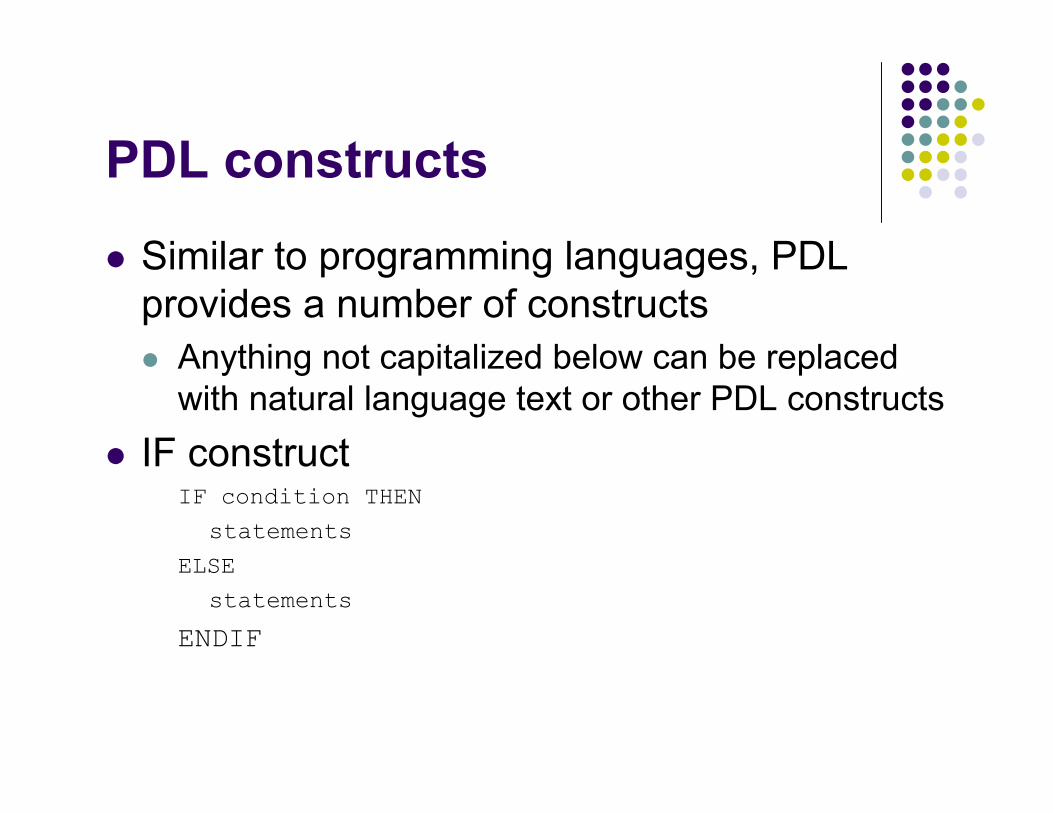
PDL constructs
Similar to programming languages, PDLprovides a number of constructs Anything not capitalized below can be replaced
with natural language text or other PDL constructs IF construct
IF condition THEN
statements
ELSE
statements
ENDIF
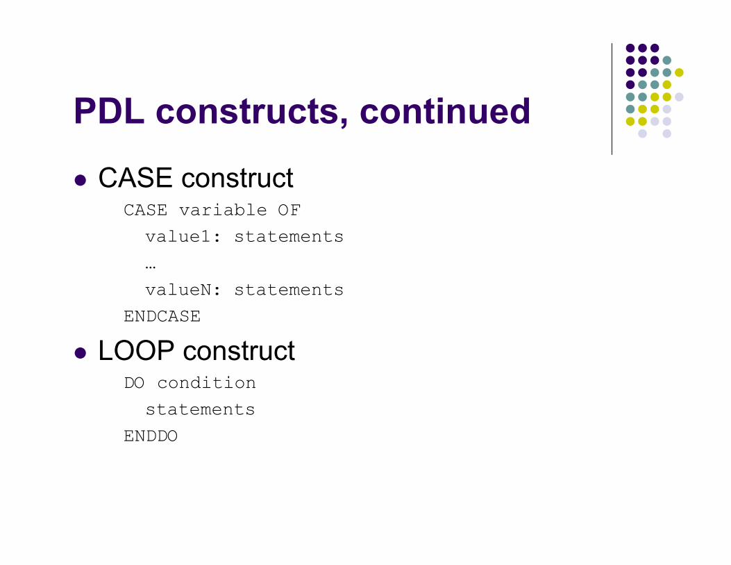
PDL constructs, continued
CASE constructCASE variable OF
value1: statements
…
valueN: statements
ENDCASE
LOOP constructDO condition
statements
ENDDO
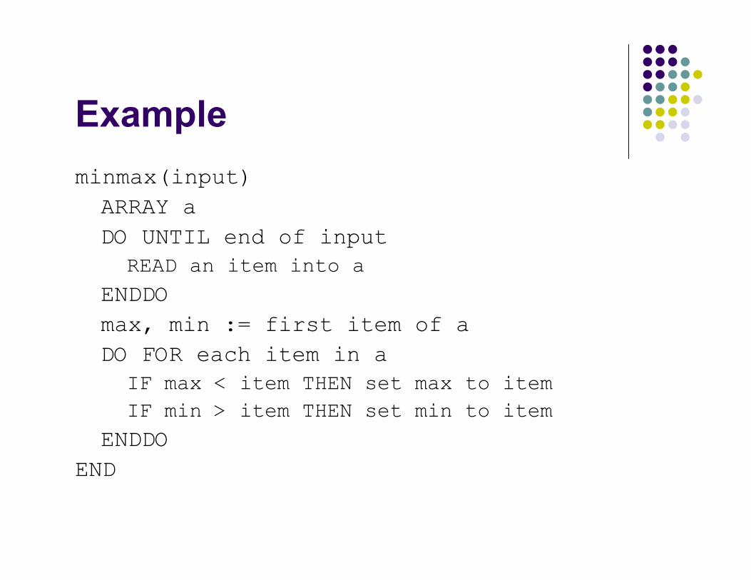
Exampleminmax(input)ARRAY aDO UNTIL end of input
READ an item into a
ENDDOmax, min := first item of aDO FOR each item in a
IF max < item THEN set max to item
IF min > item THEN set min to item
ENDDOEND
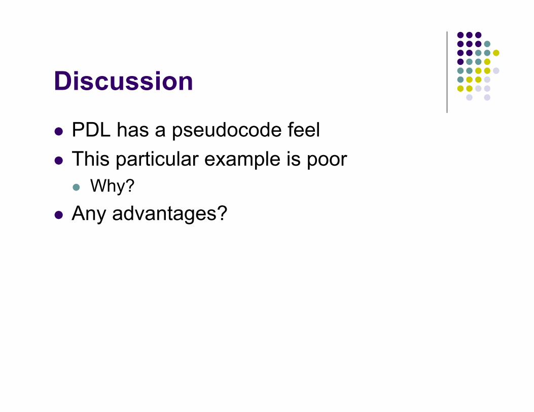
Discussion
PDL has a pseudocode feel This particular example is poor
Why? Any advantages?
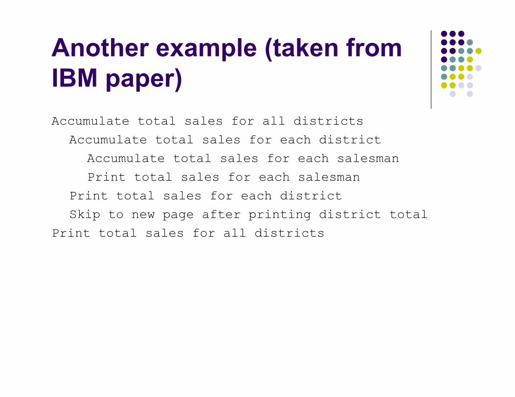
Another example (taken fromIBM paper)Accumulate total sales for all districts
Accumulate total sales for each district
Accumulate total sales for each salesman
Print total sales for each salesman
Print total sales for each district
Skip to new page after printing district total
Print total sales for all districts
Discussion
Level of abstraction is at higher level while still providing a direction for how this module
will meet its requirements If you leave out the “skip to new page”
statement and the use of the word “print”, thespecification could be implemented in anumber of ways
Other issues?

Truth in Advertising? I found the following statement on the Web
concerning PDL: <http://www.cacs.louisiana.edu/~mgr/404/burks/foldoc/37/93.htm>
“Program Design Language: Any of a large class of formaland profoundly useless pseudo-languages in whichmanagement forces one to design programs. Too often,management expects PDL descriptions to be maintainedin parallel with the code, imposing massive overhead oflittle or no benefit.
See also flow chart.”
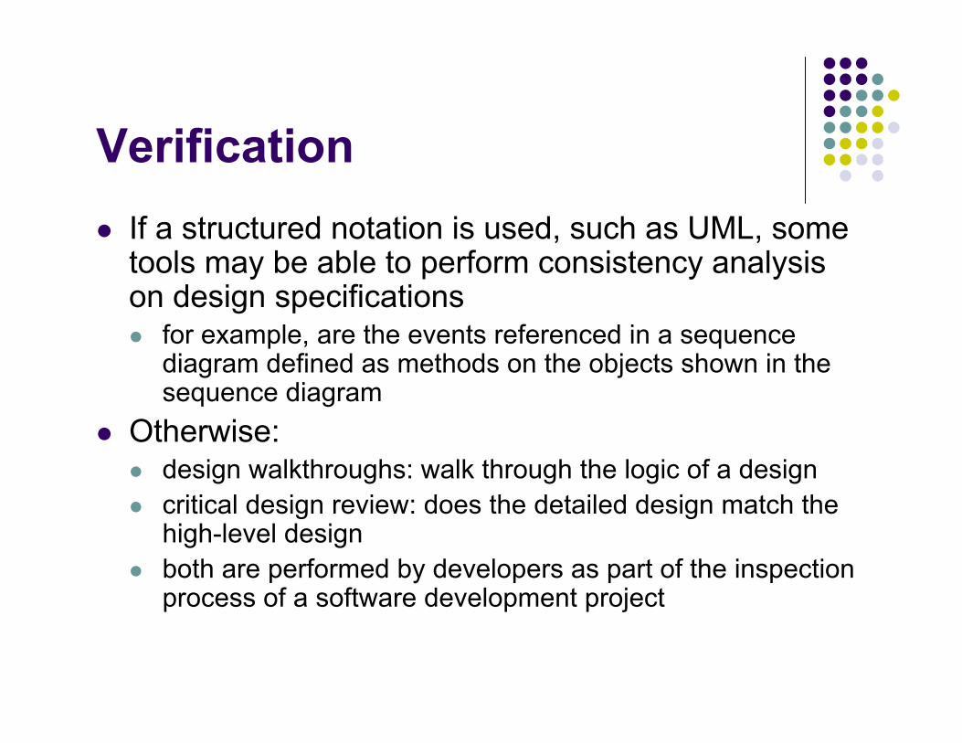
Verification If a structured notation is used, such as UML, some
tools may be able to perform consistency analysison design specifications for example, are the events referenced in a sequence
diagram defined as methods on the objects shown in thesequence diagram
Otherwise: design walkthroughs: walk through the logic of a design critical design review: does the detailed design match the
high-level design both are performed by developers as part of the inspection
process of a software development project
Metrics
Cyclomatic Complexity Data Bindings Cohesion Metric
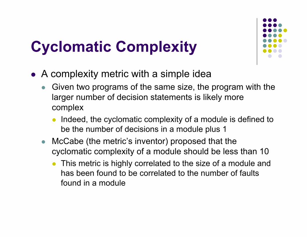
Cyclomatic Complexity A complexity metric with a simple idea
Given two programs of the same size, the program with thelarger number of decision statements is likely morecomplex Indeed, the cyclomatic complexity of a module is defined to
be the number of decisions in a module plus 1 McCabe (the metric’s inventor) proposed that the
cyclomatic complexity of a module should be less than 10 This metric is highly correlated to the size of a module and
has been found to be correlated to the number of faultsfound in a module
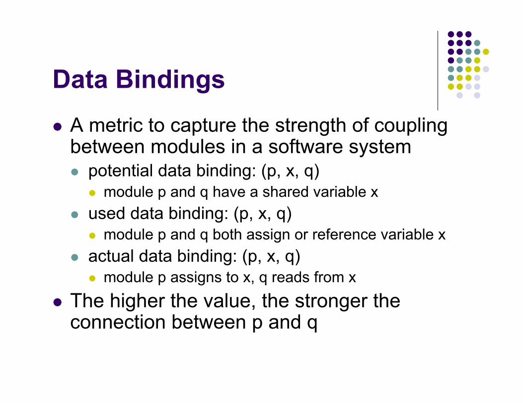
Data Bindings A metric to capture the strength of coupling
between modules in a software system potential data binding: (p, x, q)
module p and q have a shared variable x used data binding: (p, x, q)
module p and q both assign or reference variable x actual data binding: (p, x, q)
module p assigns to x, q reads from x The higher the value, the stronger the
connection between p and q
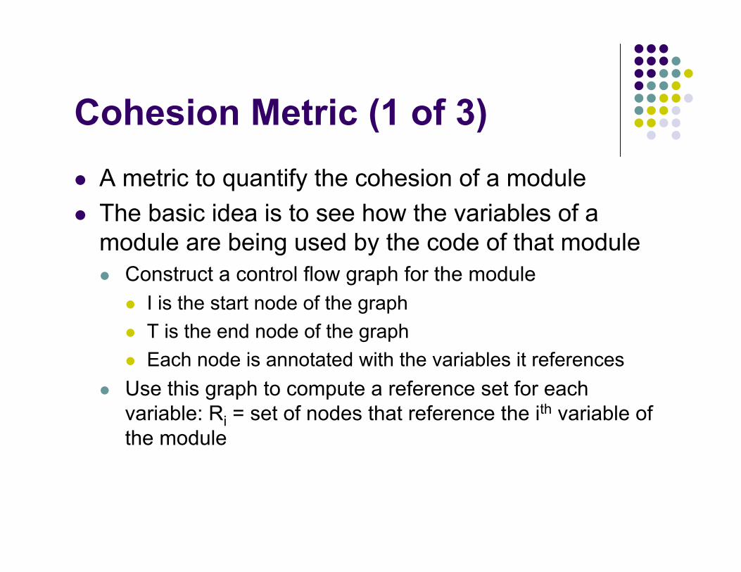
Cohesion Metric (1 of 3) A metric to quantify the cohesion of a module The basic idea is to see how the variables of a
module are being used by the code of that module Construct a control flow graph for the module
I is the start node of the graph T is the end node of the graph Each node is annotated with the variables it references
Use this graph to compute a reference set for eachvariable: Ri = set of nodes that reference the ith variable ofthe module
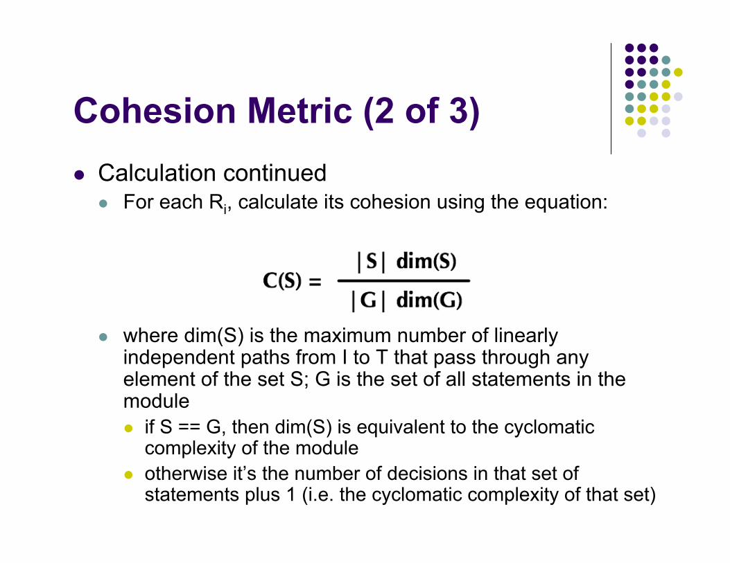
Cohesion Metric (2 of 3) Calculation continued
For each Ri, calculate its cohesion using the equation:
where dim(S) is the maximum number of linearlyindependent paths from I to T that pass through anyelement of the set S; G is the set of all statements in themodule if S == G, then dim(S) is equivalent to the cyclomatic
complexity of the module otherwise it’s the number of decisions in that set of
statements plus 1 (i.e. the cyclomatic complexity of that set)
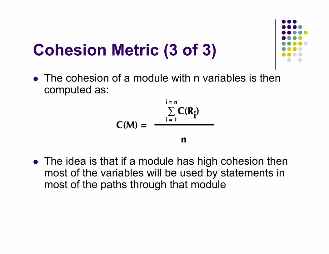
Cohesion Metric (3 of 3) The cohesion of a module with n variables is then
computed as:
The idea is that if a module has high cohesion thenmost of the variables will be used by statements inmost of the paths through that module
Summary The design of a software system is split into
two phases high-level design
a system viewed as a set of modules low-level design
providing detailed information about each module What’s next?
Chapter 7 of the concurrency textbook Other aspects of design: design patterns, design
by convention, etc.


![jeanpaulva.files.wordpress.com file · Web viewFOSTER – DETAILED DESIGN [Demonstration Document]. . Foster. DETAILED DESIGN](https://img.pdfslide.net/doc/110x75/5c8cec2909d3f2a01c8c4a6c/-web-viewfoster-detailed-design-demonstration-document-foster-detailed.jpg)