Embed Size (px)
Citation preview
P1
Detailed explanation of UN R136
May 24, 2016
Toshiyuki CHO
Japan Automobile Standards Internationalization Center
Contents
Detailed explanation of UN R1361.Background of UN R136 p3 〜p13
2.Detail of UN R136 p14〜p52
Appendix p53〜p65
Introduction of e-PTW-related ISO/IEC
P2
Contents
Detailed explanation of UN R1361.Background of UN R1362.Detail of UN R136
AppendixIntroduction of e-PTW-related ISO/IEC
P3
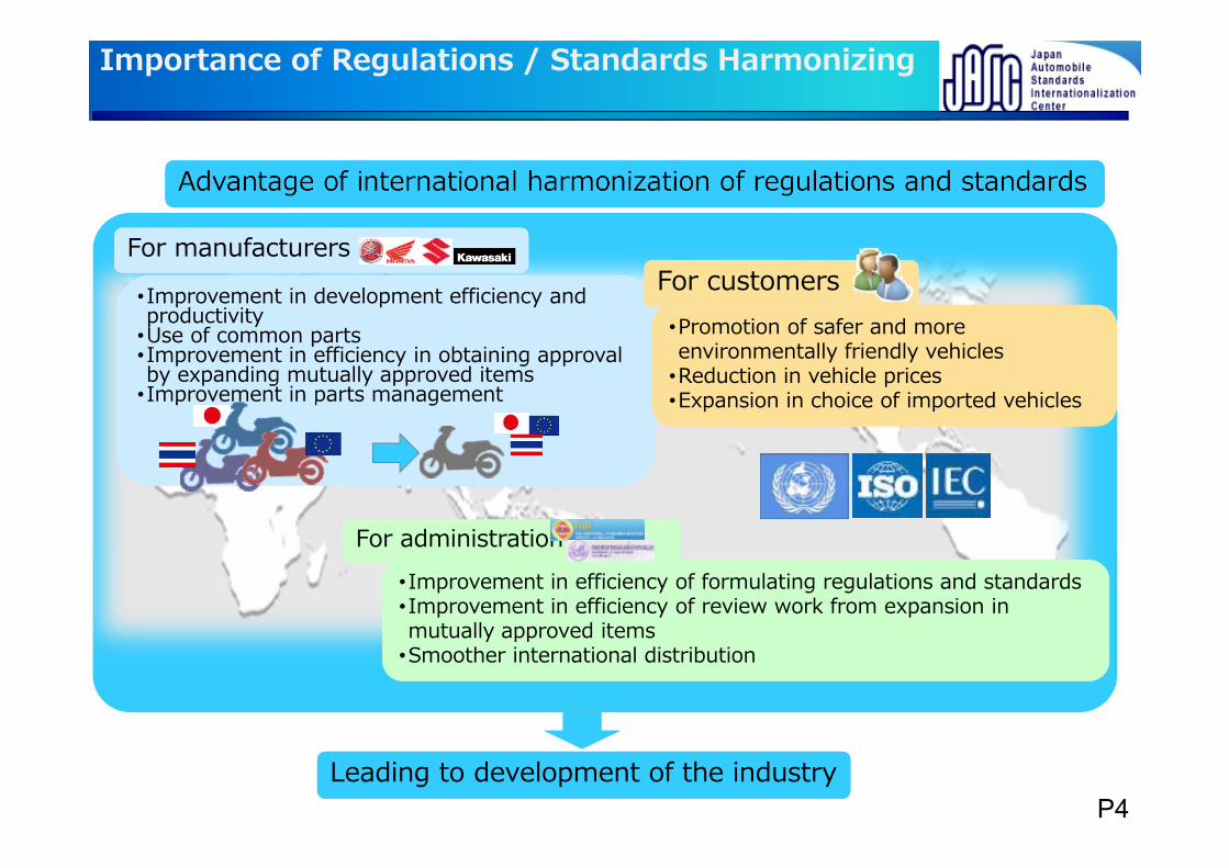
Advantage of international harmonization of regulations and standardsAdvantage of international harmonization of regulations and standards
Importance of Regulations / Standards Harmonizing
•Improvement in development efficiency and productivity
•Use of common parts•Improvement in efficiency in obtaining approval by expanding mutually approved items
•Improvement in parts management
•Improvement in development efficiency and productivity
•Use of common parts•Improvement in efficiency in obtaining approval by expanding mutually approved items
•Improvement in parts management
•Promotion of safer and more environmentally friendly vehicles
•Reduction in vehicle prices•Expansion in choice of imported vehicles
•Promotion of safer and more environmentally friendly vehicles
•Reduction in vehicle prices•Expansion in choice of imported vehicles
•Improvement in efficiency of formulating regulations and standards•Improvement in efficiency of review work from expansion in mutually approved items
•Smoother international distribution
•Improvement in efficiency of formulating regulations and standards•Improvement in efficiency of review work from expansion in mutually approved items
•Smoother international distribution
For manufacturersFor manufacturersFor customersFor customers
For administrationFor administration
Leading to development of the industryLeading to development of the industryP4
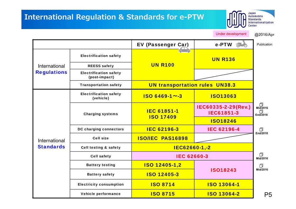
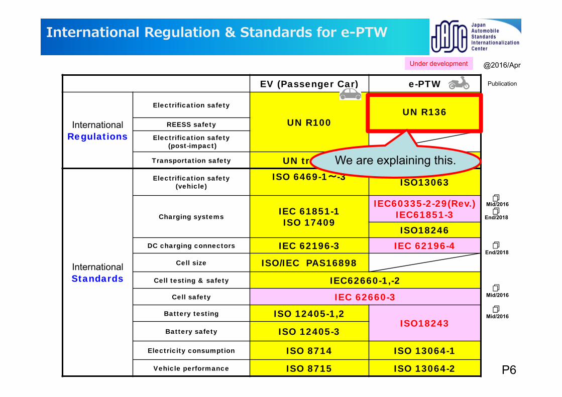
EV (Passenger Car) e-PTW
InternationalRegulations
Electrification safety
UN R100UN R136
REESS safety
Electrification safety(post-impact)
Transportation safety UN transportation rules UN38.3
International Standards
Electrification safety (vehicle) ISO 6469-1~-3 ISO13063
Charging systems IEC 61851-1ISO 17409
IEC60335-2-29(Rev.)IEC61851-3ISO18246
DC charging connectors IEC 62196-3 IEC 62196-4Cell size ISO/IEC PAS16898
Cell testing & safety IEC62660-1,-2Cell safety IEC 62660-3
Battery testing ISO 12405-1,2ISO18243
Battery safety ISO 12405-3
Electricity consumption ISO 8714 ISO 13064-1
Vehicle performance ISO 8715 ISO 13064-2
International Regulation & Standards for e-PTW
Mid/2016
End/2018
End/2018
@2016/Apr
Mid/2016
Publication
Mid/2016
Under development
P5
EV (Passenger Car) e-PTW
InternationalRegulations
Electrification safety
UN R100UN R136
REESS safety
Electrification safety(post-impact)
Transportation safety UN transportation rules UN38.3
International Standards
Electrification safety (vehicle)
ISO 6469-1~-3 ISO13063
Charging systems IEC 61851-1ISO 17409
IEC60335-2-29(Rev.)IEC61851-3ISO18246
DC charging connectors IEC 62196-3 IEC 62196-4Cell size ISO/IEC PAS16898
Cell testing & safety IEC62660-1,-2Cell safety IEC 62660-3
Battery testing ISO 12405-1,2ISO18243
Battery safety ISO 12405-3
Electricity consumption ISO 8714 ISO 13064-1
Vehicle performance ISO 8715 ISO 13064-2
International Regulation & Standards for e-PTW
Mid/2016
End/2018
End/2018
@2016/Apr
Mid/2016
Publication
Mid/2016
Under development
We are explaining this.
P6
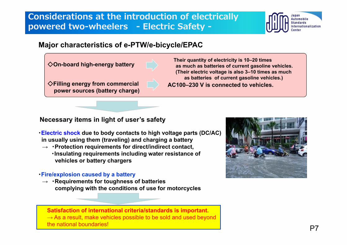
Satisfaction of international criteria/standards is important.→ As a result, make vehicles possible to be sold and used beyond the national boundaries!
Major characteristics of e-PTW/e-bicycle/EPAC
Necessary items in light of user’s safety
Considerations at the introduction of electrically powered two-wheelers - Electric Safety -
Their quantity of electricity is 10–20 times as much as batteries of current gasoline vehicles.(Their electric voltage is also 3–10 times as much
as batteries of current gasoline vehicles.)Filling energy from commercial
power sources (battery charge)AC100–230 V is connected to vehicles.
On-board high-energy battery
・Electric shock due to body contacts to high voltage parts (DC/AC) in usually using them (traveling) and charging a battery→ ・Protection requirements for direct/indirect contact,
・Insulating requirements including water resistance of vehicles or battery chargers
・Fire/explosion caused by a battery→ ・Requirements for toughness of batteries
complying with the conditions of use for motorcycles
P7
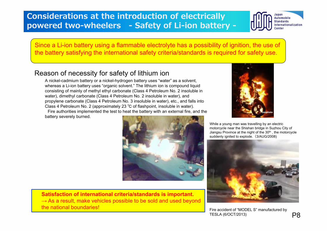
A nickel-cadmium battery or a nickel-hydrogen battery uses “water” as a solvent, whereas a Li-ion battery uses “organic solvent.” The lithium ion is compound liquid consisting of mainly of methyl ethyl carbonate (Class 4 Petroleum No. 2 insoluble in water), dimethyl carbonate (Class 4 Petroleum No. 2 insoluble in water), and propylene carbonate (Class 4 Petroleum No. 3 insoluble in water), etc., and falls into Class 4 Petroleum No. 2 (approximately 23 of flashpoint, insoluble in water).
Fire authorities implemented the test to heat the battery with an external fire, and the battery severely burned.
Reason of necessity for safety of lithium ion
While a young man was travelling by an electric motorcycle near the Shishan bridge in Suzhou City of Jiangsu Province at the night of the 30th , the motorcycle suddenly ignited to explode.(3/AUG/2008)
Fire accident of “MODEL S” manufactured by TESLA (6/OCT/2013)
Since a Li-ion battery using a flammable electrolyte has a possibility of ignition, the use of the battery satisfying the international safety criteria/standards is required for safety use.
Satisfaction of international criteria/standards is important.→ As a result, make vehicles possible to be sold and used beyond the national boundaries!
C°CConsiderations at the introduction of electrically
powered two-wheelers - Safety of Li-ion battery -
P8
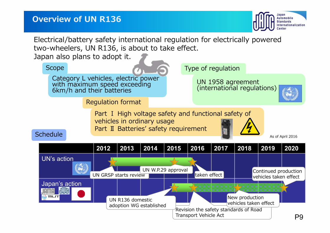
Overview of UN R136
Electrical/battery safety international regulation for electrically powered two-wheelers, UN R136, is about to take effect.Japan also plans to adopt it.
As of April 2016
Category L vehicles, electric power with maximum speed exceeding 6km/h and their batteries
Category L vehicles, electric power with maximum speed exceeding 6km/h and their batteries
ScopeScope
Part Ⅰ High voltage safety and functional safety of vehicles in ordinary usagePart Ⅱ Batteriesʼ safety requirement
Part Ⅰ High voltage safety and functional safety of vehicles in ordinary usagePart Ⅱ Batteriesʼ safety requirement
Regulation formatRegulation format
UN 1958 agreement (international regulations)UN 1958 agreement (international regulations)
Type of regulationType of regulation
ScheduleSchedule
2012 2013 2014 2015 2016 2017 2018 2019 2020UN’s action
Japan’s actiontaken effect
Revision the safety standards of Road Transport Vehicle Act
UN GRSP starts reviewUN W.P.29 approval
UN R136 domestic adoption WG established
New production vehicles taken effect
Continued production vehicles taken effect
P9
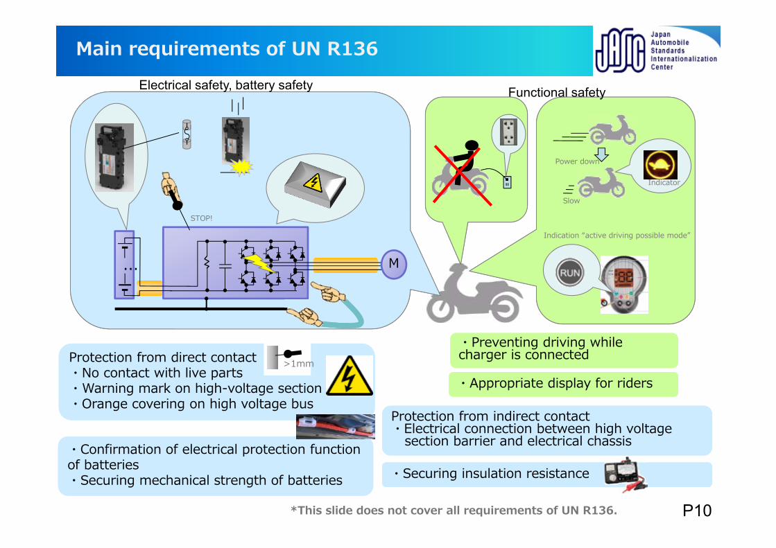
Protection from direct contact・No contact with live parts・Warning mark on high-voltage section・Orange covering on high voltage bus
Protection from direct contact・No contact with live parts・Warning mark on high-voltage section・Orange covering on high voltage bus
Main requirements of UN R136
M...
Protection from indirect contact・Electrical connection between high voltage
section barrier and electrical chassis
Protection from indirect contact・Electrical connection between high voltage
section barrier and electrical chassis
STOP!
・Securing insulation resistance・Securing insulation resistance
>1mm
・Confirmation of electrical protection function of batteries・Securing mechanical strength of batteries
・Confirmation of electrical protection function of batteries・Securing mechanical strength of batteries
・Appropriate display for riders・Appropriate display for riders
・Preventing driving while charger is connected・Preventing driving while charger is connected
*This slide does not cover all requirements of UN R136.
Slow
Indicator
Indication “active driving possible mode”
Power down
Electrical safety, battery safety Functional safety
P10
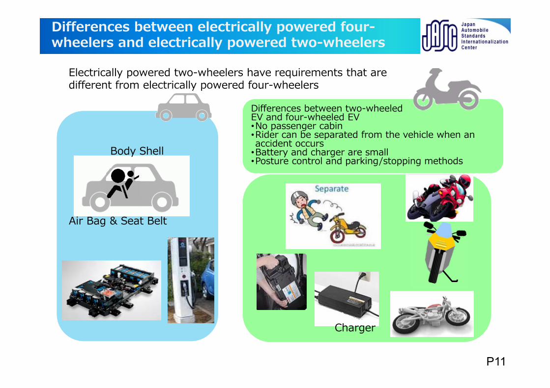
Differences between electrically powered four-wheelers and electrically powered two-wheelers
Electrically powered two-wheelers have requirements that are different from electrically powered four-wheelers
Differences between two-wheeled EV and four-wheeled EV•No passenger cabin•Rider can be separated from the vehicle when an accident occurs
•Battery and charger are small•Posture control and parking/stopping methods
Differences between two-wheeled EV and four-wheeled EV•No passenger cabin•Rider can be separated from the vehicle when an accident occurs
•Battery and charger are small•Posture control and parking/stopping methods
Body Shell
Air Bag & Seat Belt
Charger
P11
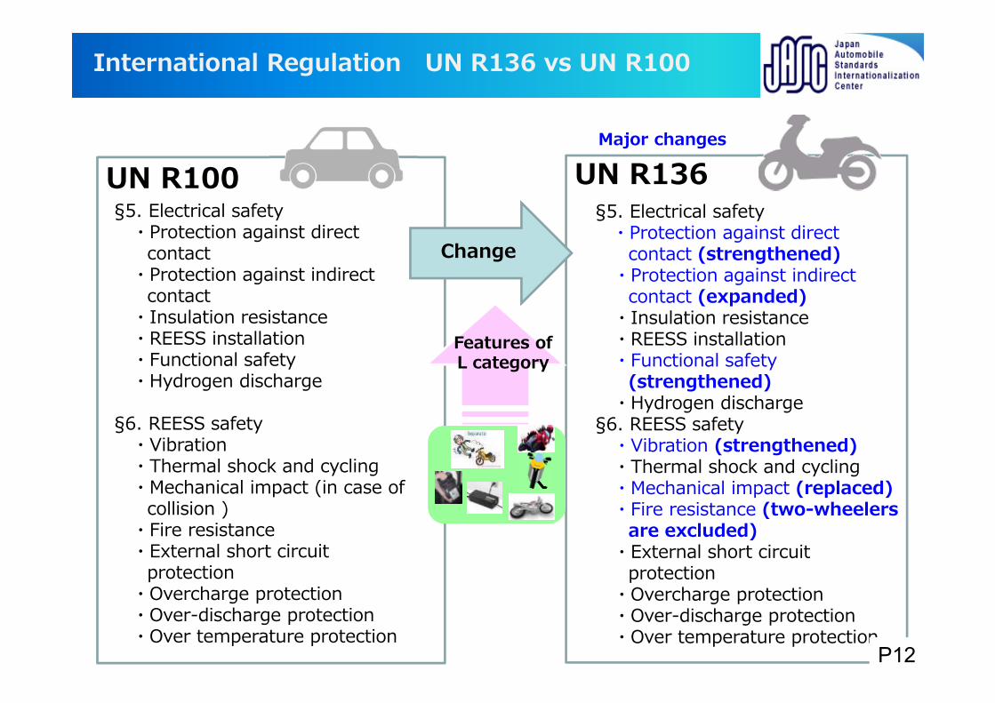
International Regulation UN R136 vs UN R100
UN R100§5. Electrical safety
・Protection against direct contact
・Protection against indirect contact
・Insulation resistance・REESS installation・Functional safety・Hydrogen discharge
§6. REESS safety・Vibration・Thermal shock and cycling・Mechanical impact (in case of
collision )・Fire resistance・External short circuit
protection・Overcharge protection・Over-discharge protection・Over temperature protection
UN R136§5. Electrical safety
・Protection against direct contact (strengthened)
・Protection against indirect contact (expanded)
・Insulation resistance・REESS installation・Functional safety
(strengthened) ・Hydrogen discharge
§6. REESS safety・Vibration (strengthened) ・Thermal shock and cycling・Mechanical impact (replaced)・Fire resistance (two-wheelers
are excluded)・External short circuit
protection・Overcharge protection・Over-discharge protection・Over temperature protection
Major changes
Change
Features of L category
P12
• Appropriate EV regulations are necessary for the peopleʼs safety.
• The international regulations for Category L EVʼs electricity and REESS safety have gone into effect in January 2016. Japan also have adopted them and revised relevant laws and regulations at the time of enactment.
• To protect the peopleʼs safety and develop the EV industry in a sound manner, JASIC recommends also to establish electricity and REESS safety regulations for Category L EV harmonized with UN R136.
Summary & JASIC proposal- Detailed explanation of UN R136 -
P13
Contents
Detailed explanation of UN R1361.Background of UN R1362.Detail of UN R136
AppendixIntroduction of e-PTW-related ISO/IEC
*A change part from R100 is indicated by the red character.
P14
§1. Scope
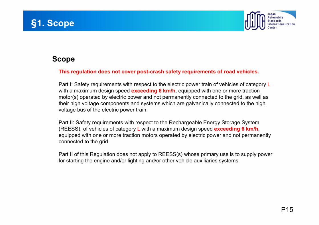
This regulation does not cover post-crash safety requirements of road vehicles.
Part I: Safety requirements with respect to the electric power train of vehicles of category Lwith a maximum design speed exceeding 6 km/h, equipped with one or more traction motor(s) operated by electric power and not permanently connected to the grid, as well as their high voltage components and systems which are galvanically connected to the high voltage bus of the electric power train.
Part II: Safety requirements with respect to the Rechargeable Energy Storage System (REESS), of vehicles of category L with a maximum design speed exceeding 6 km/h, equipped with one or more traction motors operated by electric power and not permanently connected to the grid.
Part II of this Regulation does not apply to REESS(s) whose primary use is to supply power for starting the engine and/or lighting and/or other vehicle auxiliaries systems.
Scope
P15
Individual examination contents and requirements
§5 Part Ⅰ:
Requirements of a vehicle with regard to its electrical safety
P16
Protection against direct contact/requirements for vehicles without cabin §5.1.1.1.〜2.
Objective Criteria
General conditions
Typical individual conditions
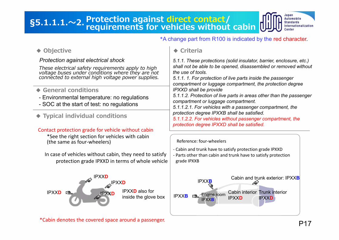
These electrical safety requirements apply to high voltage buses under conditions where they are not connected to external high voltage power supplies.
5.1.1. These protections (solid insulator, barrier, enclosure, etc.) shall not be able to be opened, disassembled or removed without the use of tools.5.1.1. 1. For protection of live parts inside the passenger compartment or luggage compartment, the protection degree IPXXD shall be provide5.1.1.2. Protection of live parts in areas other than the passenger compartment or luggage compartment.5.1.1.2.1. For vehicles with a passenger compartment, the protection degree IPXXB shall be satisfied.5.1.1.2.2. For vehicles without passenger compartment, the protection degree IPXXD shall be satisfied.
- Environmental temperature: no regulations- SOC at the start of test: no regulations
*Cabin denotes the covered space around a passenger.
Cabin interiorIPXXD
Trunk interiorIPXXD
IPXXB
IPXXB
Cabin and trunk exterior: IPXXB
Engine roomIPXXB
IPXXD
IPXXD
IPXXD
IPXXD
IPXXD also for inside the glove box
Contact protection grade for vehicle without cabin
Reference: four‐wheelers*See the right section for vehicles with cabin(the same as four‐wheelers)
In case of vehicles without cabin, they need to satisfy protection grade IPXXD in terms of whole vehicle
‐ Cabin and trunk have to satisfy protection grade IPXXD‐ Parts other than cabin and trunk have to satisfy protection grade IPXXB
Protection against electrical shock
*A change part from R100 is indicated by the red character.
P17
Criteria
General conditions
Typical individual conditions
d)
IPXXB or IPXXD
a)
b)
c)
IPXXB or IPXXD
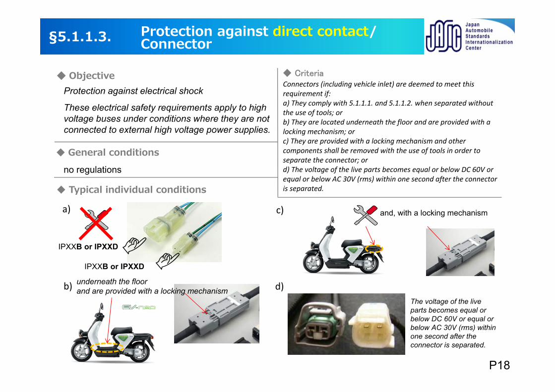
These electrical safety requirements apply to high voltage buses under conditions where they are not connected to external high voltage power supplies.
Connectors (including vehicle inlet) are deemed to meet this requirement if:a) They comply with 5.1.1.1. and 5.1.1.2. when separated without the use of tools; orb) They are located underneath the floor and are provided with a locking mechanism; orc) They are provided with a locking mechanism and other components shall be removed with the use of tools in order to separate the connector; ord) The voltage of the live parts becomes equal or below DC 60V or equal or below AC 30V (rms) within one second after the connector is separated.
underneath the floor and are provided with a locking mechanism
The voltage of the live parts becomes equal or below DC 60V or equal or below AC 30V (rms) within one second after the connector is separated.
and, with a locking mechanism
Protection against direct contact/Connector§5.1.1.3.
ObjectiveProtection against electrical shock
no regulations
P18
Criteria
General conditions
Typical individual conditions
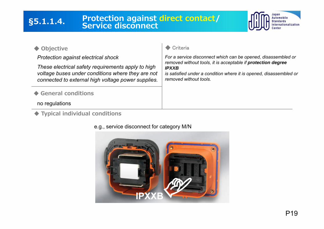
For a service disconnect which can be opened, disassembled or removed without tools, it is acceptable if protection degree IPXXB is satisfied under a condition where it is opened, disassembled or removed without tools.
IPXXB
e.g., service disconnect for category M/N
These electrical safety requirements apply to high voltage buses under conditions where they are not connected to external high voltage power supplies.
Protection against direct contact/Service disconnect§5.1.1.4.
ObjectiveProtection against electrical shock
no regulations
P19
Criteria
General conditions
Typical individual conditions
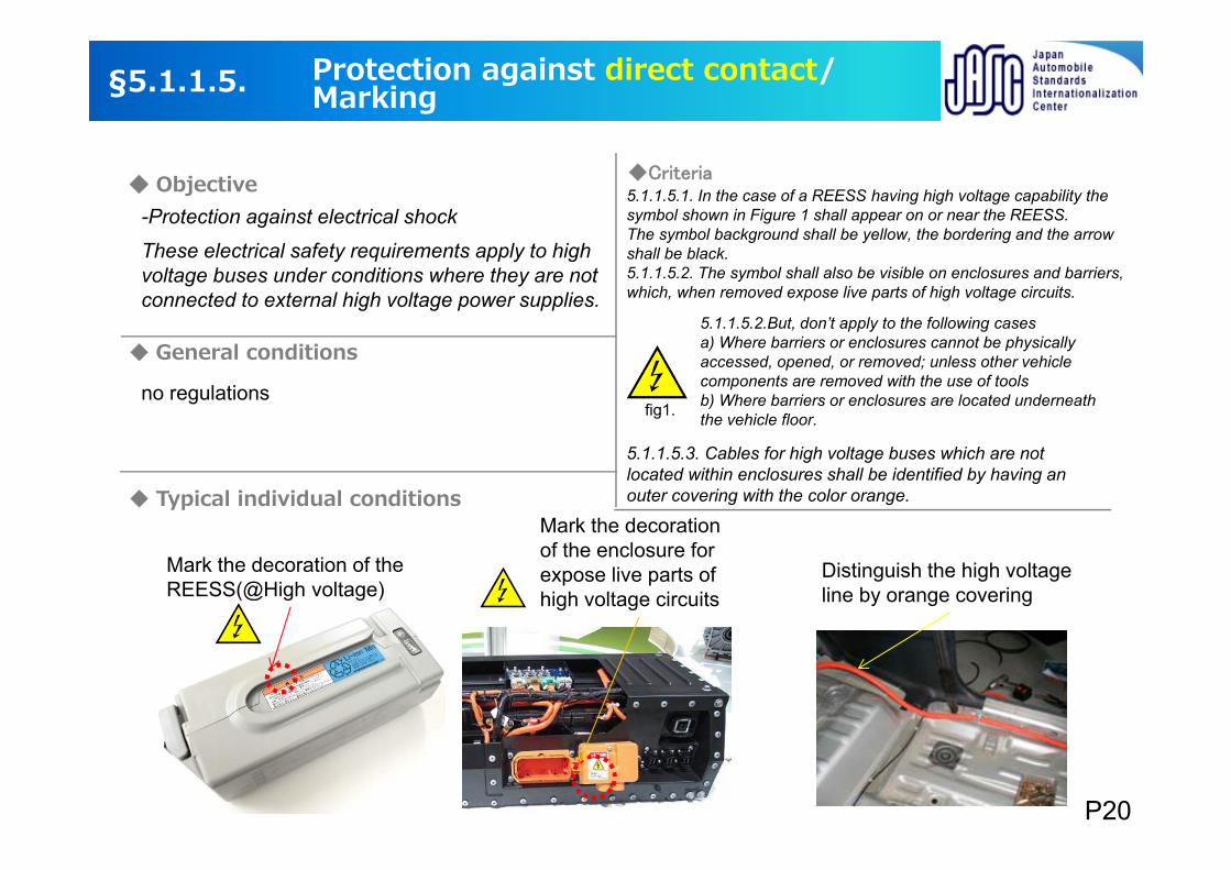
Mark the decoration of the REESS(@High voltage)
Mark the decoration of the enclosure for expose live parts of high voltage circuits
5.1.1.5.1. In the case of a REESS having high voltage capability the symbol shown in Figure 1 shall appear on or near the REESS. The symbol background shall be yellow, the bordering and the arrow shall be black.5.1.1.5.2. The symbol shall also be visible on enclosures and barriers, which, when removed expose live parts of high voltage circuits.
5.1.1.5.2.But, don’t apply to the following casesa) Where barriers or enclosures cannot be physically accessed, opened, or removed; unless other vehicle components are removed with the use of toolsb) Where barriers or enclosures are located underneath the vehicle floor.
5.1.1.5.3. Cables for high voltage buses which are not located within enclosures shall be identified by having an outer covering with the color orange.
Distinguish the high voltage line by orange covering
-Protection against electrical shock
These electrical safety requirements apply to high voltage buses under conditions where they are not connected to external high voltage power supplies.
Protection against direct contact/Marking§5.1.1.5.
fig1.
Objective
no regulations
P20
Criteria
General conditions
Typical individual conditions
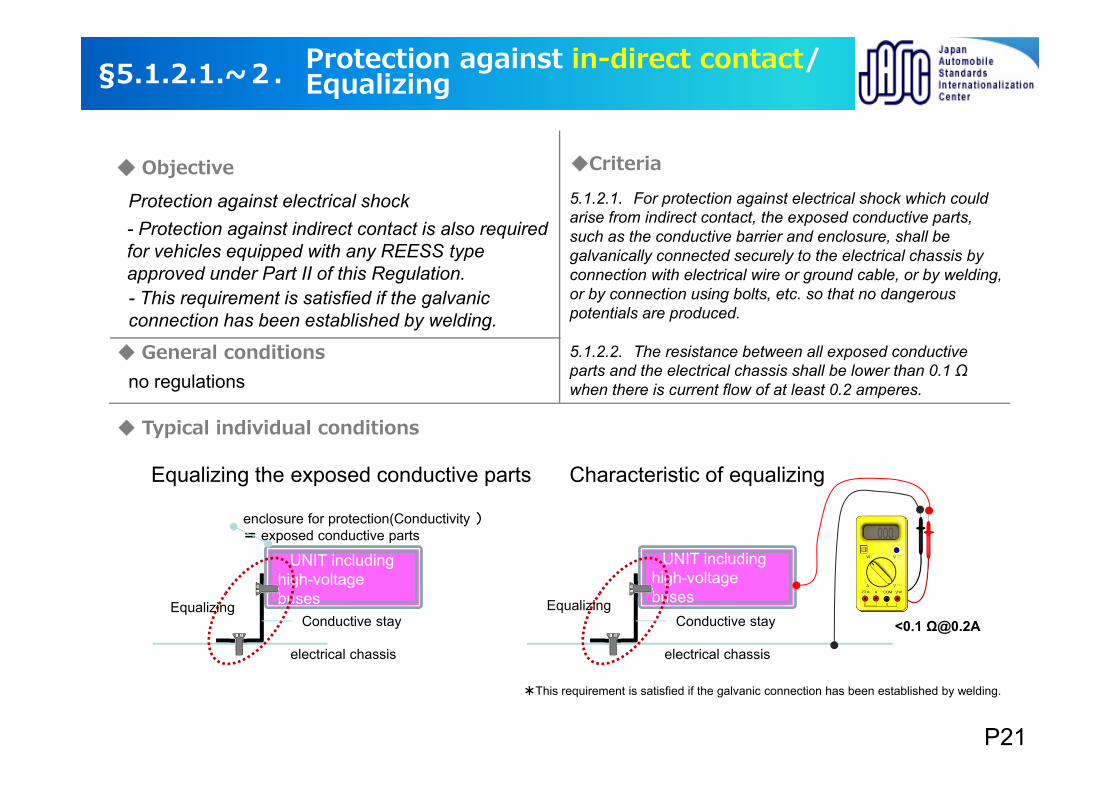
- Protection against indirect contact is also required for vehicles equipped with any REESS type approved under Part II of this Regulation.- This requirement is satisfied if the galvanic connection has been established by welding.
5.1.2.1. For protection against electrical shock which could arise from indirect contact, the exposed conductive parts, such as the conductive barrier and enclosure, shall be galvanically connected securely to the electrical chassis by connection with electrical wire or ground cable, or by welding, or by connection using bolts, etc. so that no dangerous potentials are produced.
5.1.2.2. The resistance between all exposed conductive parts and the electrical chassis shall be lower than 0.1 Ω when there is current flow of at least 0.2 amperes.
Equalizing the exposed conductive parts
UNIT including high-voltage buses
enclosure for protection(Conductivity )= exposed conductive parts
electrical chassis
Conductive stayEqualizing
UNIT including high-voltage buses
<0.1 Ω@0.2A
electrical chassis
Conductive stayEqualizing
*This requirement is satisfied if the galvanic connection has been established by welding.
Characteristic of equalizing
Protection against electrical shock
Protection against in-direct contact/Equalizing§5.1.2.1.~2.
Objective
no regulations
P21
Criteria
General conditions
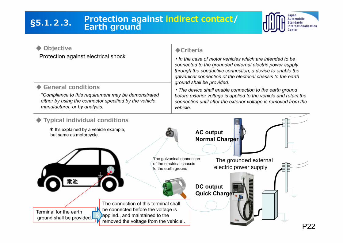
・ In the case of motor vehicles which are intended to be connected to the grounded external electric power supply through the conductive connection, a device to enable the galvanical connection of the electrical chassis to the earth ground shall be provided.・ The device shall enable connection to the earth ground before exterior voltage is applied to the vehicle and retain the connection until after the exterior voltage is removed from the vehicle.
The grounded external electric power supply
AC outputNormal Charger
DC outputQuick Charger
電池
Terminal for the earthground shall be provided.
The galvanical connection of the electrical chassis to the earth ground
The connection of this terminal shall be connected before the voltage is applied., and maintained to the removed the voltage from the vehicle..
&
* It's explained by a vehicle example,but same as motorcycle.
Protection against electrical shock
Protection against indirect contact/Earth ground§5.1.2.3.
Objective
Typical individual conditions
*Compliance to this requirement may be demonstrated either by using the connector specified by the vehicle manufacturer, or by analysis.
P22
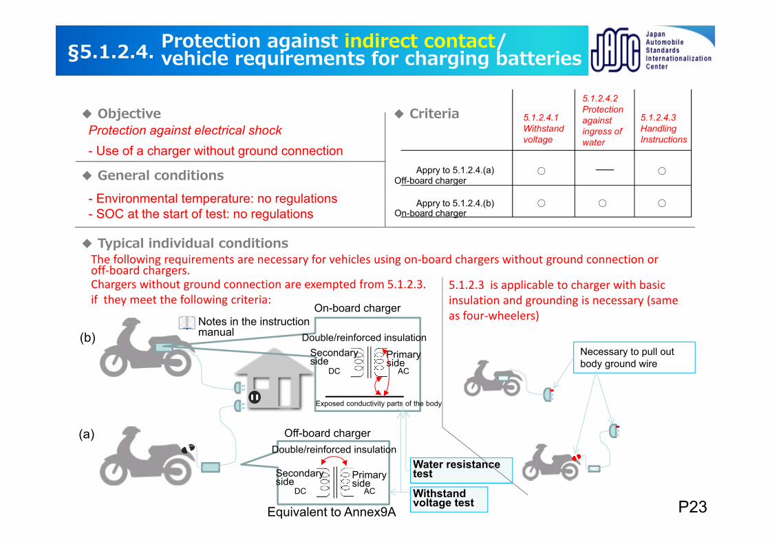
The following requirements are necessary for vehicles using on‐board chargers without ground connection or off‐board chargers.
5.1.2.3 is applicable to charger with basic insulation and grounding is necessary (same as four‐wheelers)
Chargers without ground connection are exempted from 5.1.2.3. if they meet the following criteria:
On-board charger
DC AC
Secondaryside
Primaryside
DC AC
Double/reinforced insulation
Off-board charger
Exposed conductivity parts of the body
Water resistancetest
Necessary to pull out body ground wire
Equivalent to Annex9A
Notes in the instruction manual
Withstand voltage test
§5.1.2.4.
Objective Criteria
General conditions
Typical individual conditions
- Environmental temperature: no regulations- SOC at the start of test: no regulations
Protection against indirect contact/vehicle requirements for charging batteries
Secondaryside
Primaryside
Double/reinforced insulation
Protection against electrical shock- Use of a charger without ground connection
5.1.2.4.1Withstand voltage
5.1.2.4.2Protection against ingress of water
5.1.2.4.3Handling Instructions
Appry to 5.1.2.4.(a)
Appry to 5.1.2.4.(b)
P23
(a)
(b)
On-board charger
Off-board charger
Objective Criteria
General conditions
Typical individual conditions
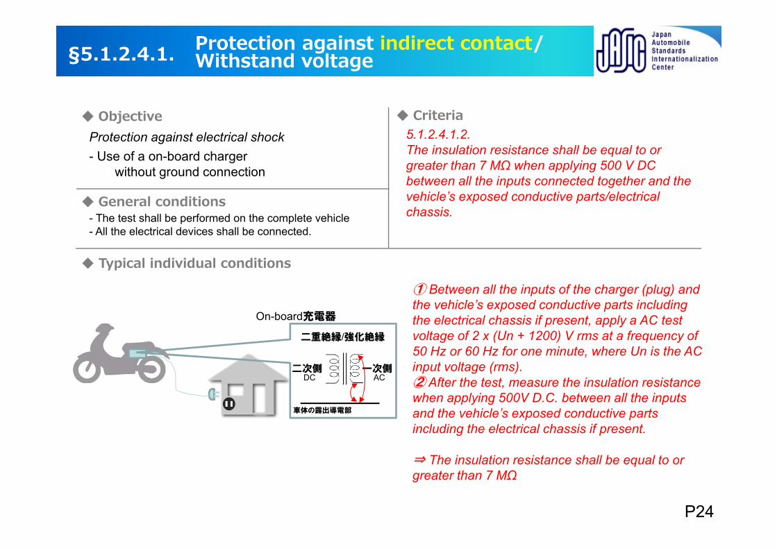
5.1.2.4.1.2.The insulation resistance shall be equal to or greater than 7 MΩ when applying 500 V DC between all the inputs connected together and the vehicle’s exposed conductive parts/electrical chassis.- The test shall be performed on the complete vehicle
- All the electrical devices shall be connected.
On-board充電器
二次側 一次側DC AC
二重絶縁/強化絶縁
車体の露出導電部
① Between all the inputs of the charger (plug) and the vehicle’s exposed conductive parts including the electrical chassis if present, apply a AC test voltage of 2 x (Un + 1200) V rms at a frequency of 50 Hz or 60 Hz for one minute, where Un is the AC input voltage (rms).② After the test, measure the insulation resistance when applying 500V D.C. between all the inputs and the vehicle’s exposed conductive parts including the electrical chassis if present.
⇒ The insulation resistance shall be equal to or greater than 7 MΩ
§5.1.2.4.1. Protection against indirect contact/Withstand voltage
Protection against electrical shock- Use of a on-board charger
without ground connection
P24

Objective Criteria
General conditions
Typical individual conditions
5.1.2.4.2.2. After the TEST ,
In accordance with the test procedure to evaluate IPX5 protection against ingress of water.
・Internal diameter of the nozzle: 6.3 mm;・Delivery rate: 12.5 l/min ± 5 per cent;・Water pressure: to be adjusted to achieve the specified delivery rate;・Core of the substantial stream: circle of approximately 40 mm diameter
at 2.5 m distance from nozzle;・Test duration per square metre of enclosure surface area likely to be
sprayed: 1 min;・Minimum test duration: 3 min;・Distance from nozzle to enclosure surface: between 2.5 m and 3 m.
2.5m~3m
Test condition
§5.1.2.4.2. Protection against indirect contact/Protection against ingress of water
Protection against electrical shock
- Vehicle Test- SOC at the start of test: no regulations
Spraying with a stream of fresh water the enclosure from all practicable directions .
- for vehicle with on-board charger without ground connection
The insulation resistance shall be equal to or greater than 7 MΩ, when applying 500 V DC.
P25
Objective Criteria
General conditions
Typical individual conditions
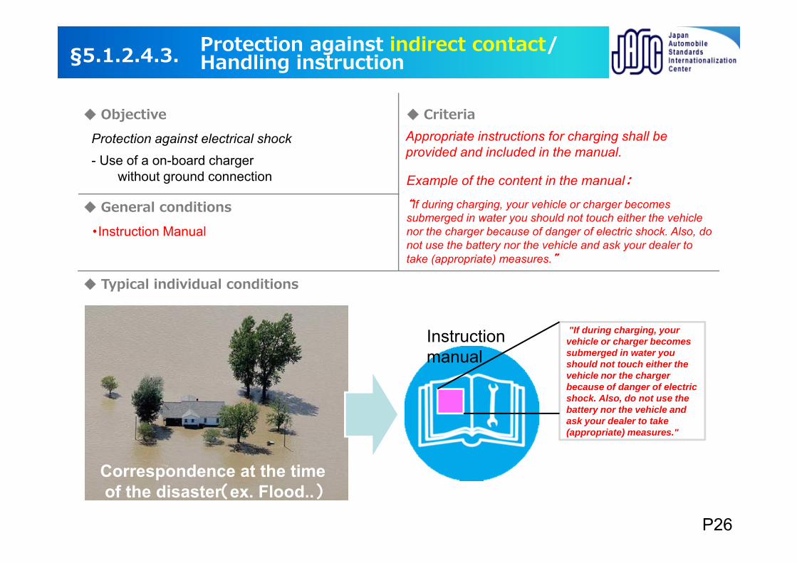
Appropriate instructions for charging shall be provided and included in the manual.
・Instruction Manual
Example of the content in the manual:
“If during charging, your vehicle or charger becomes submerged in water you should not touch either the vehicle nor the charger because of danger of electric shock. Also, do not use the battery nor the vehicle and ask your dealer to take (appropriate) measures.”
Instruction manual
Correspondence at the timeof the disaster(ex. Flood..)
"If during charging, your vehicle or charger becomes submerged in water you should not touch either the vehicle nor the charger because of danger of electric shock. Also, do not use the battery nor the vehicle and ask your dealer to take (appropriate) measures."
§5.1.2.4.3. Protection against indirect contact/Handling instruction
Protection against electrical shock- Use of a on-board charger
without ground connection
P26
Objective Criteria
General conditions
Typical individual conditions
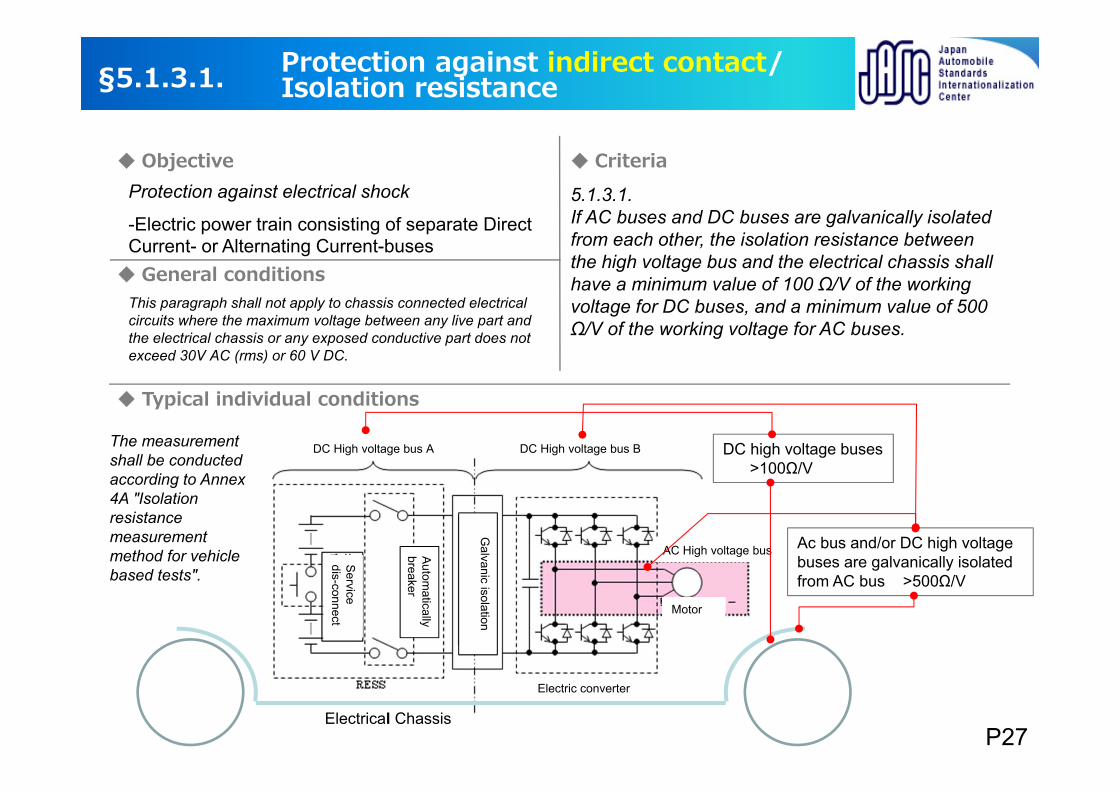
5.1.3.1.If AC buses and DC buses are galvanically isolated from each other, the isolation resistance between the high voltage bus and the electrical chassis shall have a minimum value of 100 Ω/V of the working voltage for DC buses, and a minimum value of 500 Ω/V of the working voltage for AC buses.
This paragraph shall not apply to chassis connected electrical circuits where the maximum voltage between any live part and the electrical chassis or any exposed conductive part does not exceed 30V AC (rms) or 60 V DC.
DC high voltage buses>100Ω/V
Ac bus and/or DC high voltagebuses are galvanically isolated from AC bus >500Ω/V
§5.1.3.1. Protection against indirect contact/Isolation resistance
Protection against electrical shock
-Electric power train consisting of separate Direct Current- or Alternating Current-buses
The measurement shall be conducted according to Annex 4A "Isolation resistance measurement method for vehicle based tests".
Electrical ChassisP27
DC High voltage bus A DC High voltage bus B
AC High voltage bus
Motor
Electric converter
Service
dis-connect
Autom
atically breaker
Galvanic isolation
Objective Criteria
General conditions
Typical individual conditions
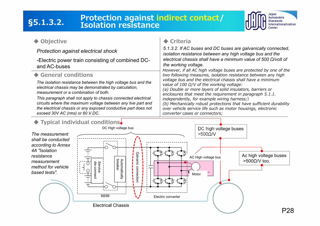
The isolation resistance between the high voltage bus and the electrical chassis may be demonstrated by calculation, measurement or a combination of both.
5.1.3.2. If AC buses and DC buses are galvanically connected, isolation resistance between any high voltage bus and the electrical chassis shall have a minimum value of 500 Ω/volt of the working voltage.However, if all AC high voltage buses are protected by one of the two following measures, isolation resistance between any high voltage bus and the electrical chassis shall have a minimum value of 100 Ω/V of the working voltage:(a) Double or more layers of solid insulators, barriers or enclosures that meet the requirement in paragraph 5.1.1. independently, for example wiring harness;)(b) Mechanically robust protections that have sufficient durability over vehicle service life such as motor housings, electronic converter cases or connectors;
This paragraph shall not apply to chassis connected electrical circuits where the maximum voltage between any live part and the electrical chassis or any exposed conductive part does not exceed 30V AC (rms) or 60 V DC.
DC high voltege buses>500Ω/V
Ac high voltege buses>500Ω/V too.
直流電気的接続
§5.1.3.2. Protection against indirect contact/Isolation resistance
Protection against electrical shock
-Electric power train consisting of combined DC-and AC-buses
The measurement shall be conducted according to Annex 4A "Isolation resistance measurement method for vehicle based tests".
Electrical ChassisP28
Galvanic connection
DC High voltage bus
AC High voltage bus
Motor
Service
dis-connect
Autom
atically breaker
Electric converter
Objective Criteria
General conditions
Typical individual conditions
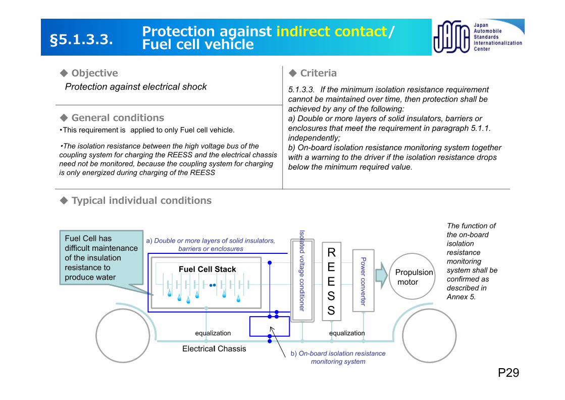
・This requirement is applied to only Fuel cell vehicle.
5.1.3.3. If the minimum isolation resistance requirement cannot be maintained over time, then protection shall be achieved by any of the following:a) Double or more layers of solid insulators, barriers or enclosures that meet the requirement in paragraph 5.1.1. independently;b) On-board isolation resistance monitoring system together with a warning to the driver if the isolation resistance drops below the minimum required value.
Fuel Cell Stack
・・
Fuel Cell has difficult maintenance of the insulation resistance to produce water
絶縁型電圧調整器
電力変換装置
REESS
b)絶縁抵抗監視システム
§5.1.3.3. Protection against indirect contact/Fuel cell vehicle
Protection against electrical shock
The function of the on-board isolation resistance monitoring system shall be confirmed as described in Annex 5.
・The isolation resistance between the high voltage bus of the coupling system for charging the REESS and the electrical chassis need not be monitored, because the coupling system for charging is only energized during charging of the REESS
Electrical Chassis
Propulsionmotor
P29
a) Double or more layers of solid insulators, barriers or enclosures
equalization equalization
b) On-board isolation resistance monitoring system
Isolated voltage conditioner
Pow
er converter
Objective Criteria
General conditions
Typical individual conditions
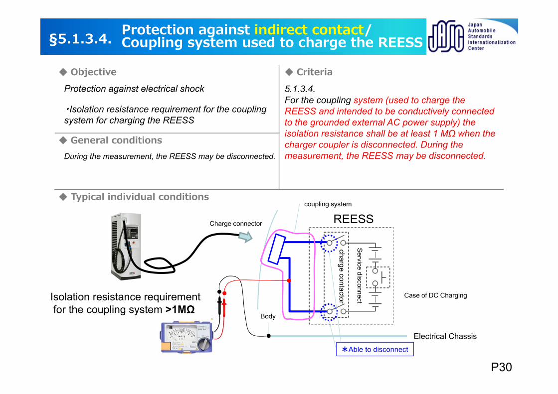
・Isolation resistance requirement for the coupling system for charging the REESS
During the measurement, the REESS may be disconnected.
5.1.3.4.For the coupling system (used to charge the REESS and intended to be conductively connected to the grounded external AC power supply) the isolation resistance shall be at least 1 MΩ when the charger coupler is disconnected. During the measurement, the REESS may be disconnected.
Service disconnect
charge contactorREESSCharge connector
Case of DC Charging
Body
Electrical Chassis
coupling system
*Able to disconnect
§5.1.3.4. Protection against indirect contact/Coupling system used to charge the REESS
Protection against electrical shock
Isolation resistance requirementfor the coupling system >1MΩ
P30
Objective Criteria
General conditions
Typical individual conditions
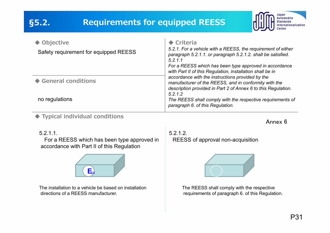
5.2.1. For a vehicle with a REESS, the requirement of either paragraph 5.2.1.1. or paragraph 5.2.1.2. shall be satisfied.5.2.1.1For a REESS which has been type approved in accordance with Part II of this Regulation, installation shall be in accordance with the instructions provided by the manufacturer of the REESS, and in conformity with the description provided in Part 2 of Annex 6 to this Regulation.5.2.1.2The REESS shall comply with the respective requirements of paragraph 6. of this Regulation.
Annex 6
5.2.1.1.For a REESS which has been type approved in
accordance with Part II of this Regulation
5.2.1.2.REESS of approval non-acquisition
The installation to a vehicle be based on installationdirections of a REESS manufacturer.
The REESS shall comply with the respectiverequirements of paragraph 6. of this Regulation.
E04
§5.2. Requirements for equipped REESS
Safety requirement for equipped REESS
no regulations
P31
Objective Criteria
General conditions
Typical individual conditions
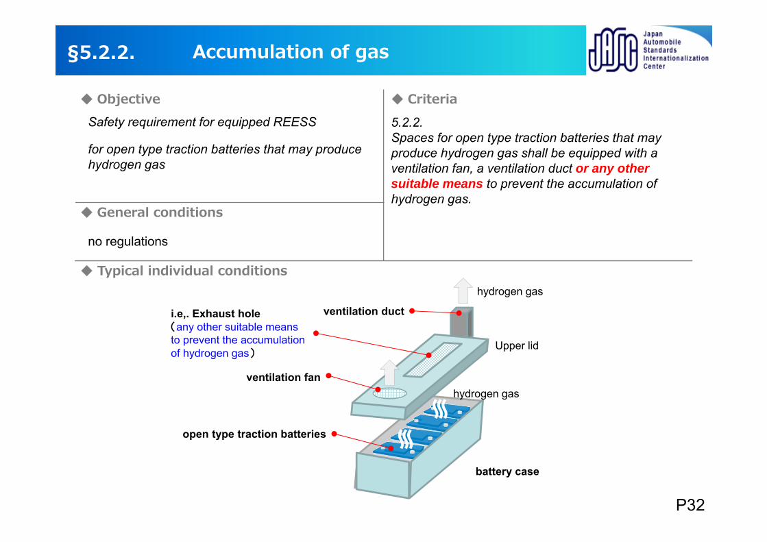
for open type traction batteries that may produce hydrogen gas
5.2.2. Spaces for open type traction batteries that may produce hydrogen gas shall be equipped with a ventilation fan, a ventilation duct or any other suitable means to prevent the accumulation of hydrogen gas.
ventilation fan
open type traction batteries
ventilation ducti.e,. Exhaust hole(any other suitable means to prevent the accumulation of hydrogen gas)
battery case
Upper lid
§5.2.2. Accumulation of gas
Safety requirement for equipped REESS
hydrogen gas
hydrogen gas
no regulations
P32
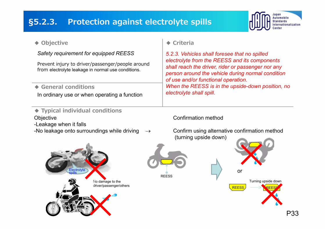
Protection against electrolyte spills
5.2.3. Vehicles shall foresee that no spilled electrolyte from the REESS and its components shall reach the driver, rider or passenger nor any person around the vehicle during normal condition of use and/or functional operation.When the REESS is in the upside-down position, no electrolyte shall spill.In ordinary use or when operating a function
Electrolyte spills
No damage to the driver/passenger/others
Objective Confirmation method-Leakage when it falls-No leakage onto surroundings while driving Confirm using alternative confirmation method
(turning upside down)
REESSTurning upside down
REESS REESS
or
§5.2.3.
Objective Criteria
General conditions
Typical individual conditions
Safety requirement for equipped REESS
Prevent injury to driver/passenger/people around from electrolyte leakage in normal use conditions.
P33
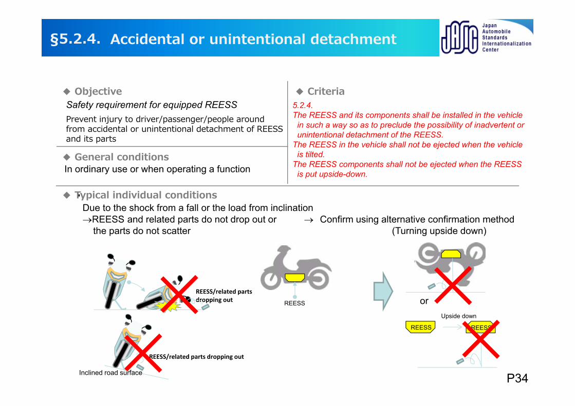
Accidental or unintentional detachment
Prevent injury to driver/passenger/people around from accidental or unintentional detachment of REESS and its parts
In ordinary use or when operating a function
5.2.4. The REESS and its components shall be installed in the vehicle
in such a way so as to preclude the possibility of inadvertent or unintentional detachment of the REESS.
The REESS in the vehicle shall not be ejected when the vehicle is tilted.
The REESS components shall not be ejected when the REESS is put upside-down.
・Due to the shock from a fall or the load from inclination REESS and related parts do not drop out or Confirm using alternative confirmation method
the parts do not scatter (Turning upside down)
REESS
Upside down
REESS REESS
orREESS/related parts dropping out
REESS/related parts dropping out
Inclined road surface
§5.2.4.
Objective Criteria
General conditions
Typical individual conditions
Safety requirement for equipped REESS
P34
Objective Criteria
General conditions
Typical individual conditions
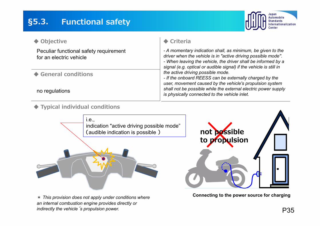
Peculiar functional safety requirement for an electric vehicle
* This provision does not apply under conditions where an internal combustion engine provides directly or indirectly the vehicle´s propulsion power.
- A momentary indication shall, as minimum, be given to the driver when the vehicle is in "active driving possible mode''. - When leaving the vehicle, the driver shall be informed by a signal (e.g. optical or audible signal) if the vehicle is still in the active driving possible mode. - If the onboard REESS can be externally charged by the user, movement caused by the vehicle's propulsion system shall not be possible while the external electric power supply is physically connected to the vehicle inlet.
Connecting to the power source for charging
i.e.,indication "active driving possible mode” (audible indication is possible )
Functional safety§5.3.
not possibleto propulsion
no regulations
P35
Objective Criteria
General conditions
Typical individual conditions
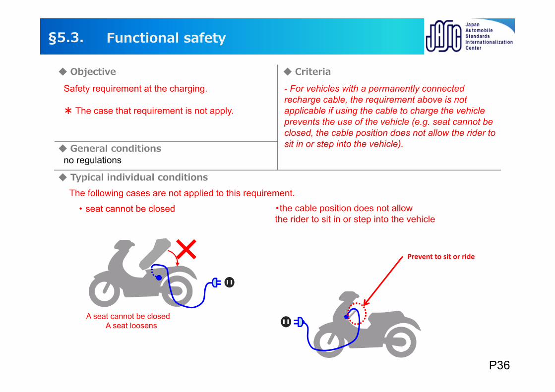
Safety requirement at the charging.
* The case that requirement is not apply.
- For vehicles with a permanently connected recharge cable, the requirement above is not applicable if using the cable to charge the vehicle prevents the use of the vehicle (e.g. seat cannot be closed, the cable position does not allow the rider to sit in or step into the vehicle).
The following cases are not applied to this requirement.
・ seat cannot be closed ・the cable position does not allow the rider to sit in or step into the vehicle
×
A seat cannot be closedA seat loosens
Functional safety§5.3.
no regulations
P36
Prevent to sit or ride
Objective Criteria
General conditions
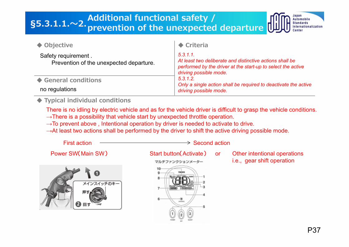
Typical individual conditionsThere is no idling by electric vehicle and as for the vehicle driver is difficult to grasp the vehicle conditions. →There is a possibility that vehicle start by unexpected throttle operation. →To prevent above , Intentional operation by driver is needed to activate to drive.→At least two actions shall be performed by the driver to shift the active driving possible mode.
Power SW(Main SW) Start button(Activate) Other intentional operationsi.e., gear shift operation
5.3.1.1.At least two deliberate and distinctive actions shall be performed by the driver at the start-up to select the active driving possible mode.5.3.1.2.Only a single action shall be required to deactivate the active driving possible mode.
Additional functional safety /prevention of the unexpected departure§5.3.1.1.〜2.
Safety requirement .Prevention of the unexpected departure.
no regulations
First action Second action
or
P37
Additional functional safety/during temporary power down
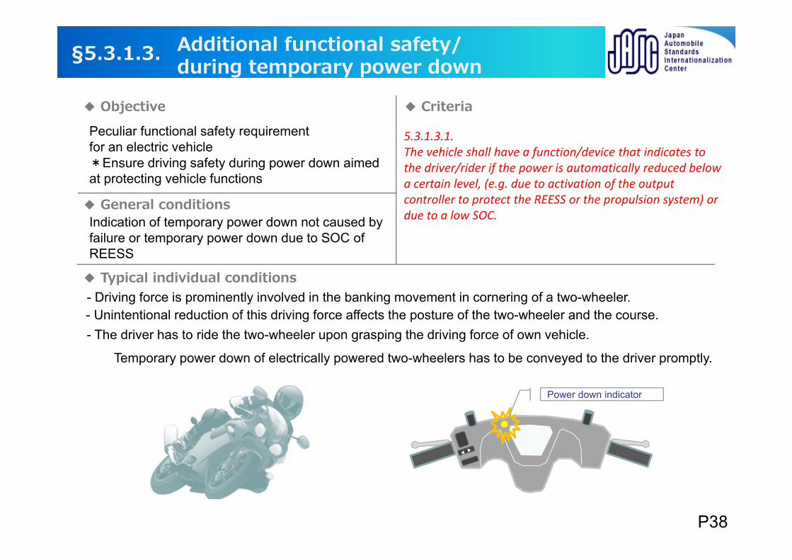
Peculiar functional safety requirement for an electric vehicle *Ensure driving safety during power down aimed at protecting vehicle functions
5.3.1.3.1.The vehicle shall have a function/device that indicates to the driver/rider if the power is automatically reduced below a certain level, (e.g. due to activation of the output controller to protect the REESS or the propulsion system) or due to a low SOC.Indication of temporary power down not caused by
failure or temporary power down due to SOC of REESS
- Driving force is prominently involved in the banking movement in cornering of a two-wheeler.- Unintentional reduction of this driving force affects the posture of the two-wheeler and the course.- The driver has to ride the two-wheeler upon grasping the driving force of own vehicle.
Temporary power down of electrically powered two-wheelers has to be conveyed to the driver promptly.
Power down indicator
§5.3.1.3.
Objective Criteria
General conditions
Typical individual conditions
P38
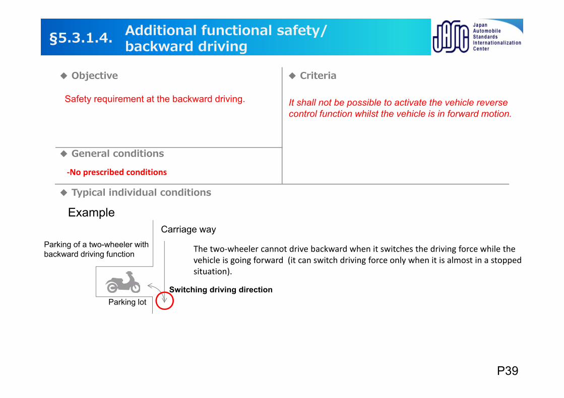
‐No prescribed conditions
It shall not be possible to activate the vehicle reverse control function whilst the vehicle is in forward motion.
Example
Parking lot
Carriage wayParking of a two-wheeler with backward driving function
Switching driving direction
The two‐wheeler cannot drive backward when it switches the driving force while the vehicle is going forward (it can switch driving force only when it is almost in a stopped situation).
§5.3.1.4.
General conditions
Typical individual conditions
Additional functional safety/backward driving
Objective Criteria
Safety requirement at the backward driving.
P39
Objective Criteria
General conditions
Typical individual conditions
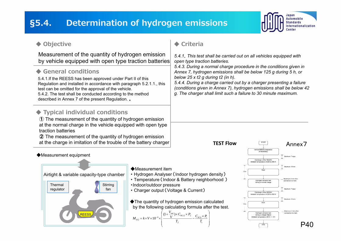
Measurement of the quantity of hydrogen emission by vehicle equipped with open type traction batteries
5.4.1.If the REESS has been approved under Part II of this Regulation and installed in accordance with paragraph 5.2.1.1., this test can be omitted for the approval of the vehicle.5.4.2. The test shall be conducted according to the method described in Annex 7 of the present Regulation. 。
5.4.1.This test shall be carried out on all vehicles equipped with open type traction batteries.5.4.3. During a normal charge procedure in the conditions given in Annex 7, hydrogen emissions shall be below 125 g during 5 h, or below 25 x t2 g during t2 (in h).5.4.4. During a charge carried out by a charger presenting a failure (conditions given in Annex 7), hydrogen emissions shall be below 42 g. The charger shall limit such a failure to 30 minute maximum.
① The measurement of the quantity of hydrogen emission at the normal charge in the vehicle equipped with open type traction batteries ② The measurement of the quantity of hydrogen emissionat the charge in imitation of the trouble of the battery charger TEST Flow
REESS
Airtight & variable capacity-type chamberMeasurement item・ Hydrogen Analyser (Indoor hydrogen density)・ Temperature (Indoor & Battery neighborhood )・Indoor/outdoor pressure・ Charger output (Voltage & Current)
Stirringfan
Measurement equipment
Thermal regulator
i
iiH
f
ffHout
H TPC
T
PCV
V
VkM 22
42
)1(10
The quantity of hydrogen emission calculated by the following calculating formula after the test.
Annex7
§5.4. Determination of hydrogen emissions
P40
Individual examination contents and requirements
§6 Part Ⅱ:
Requirements of a REESS with regard to its safety
REESS: Rechargeable Electrical Energy Storage System
P41
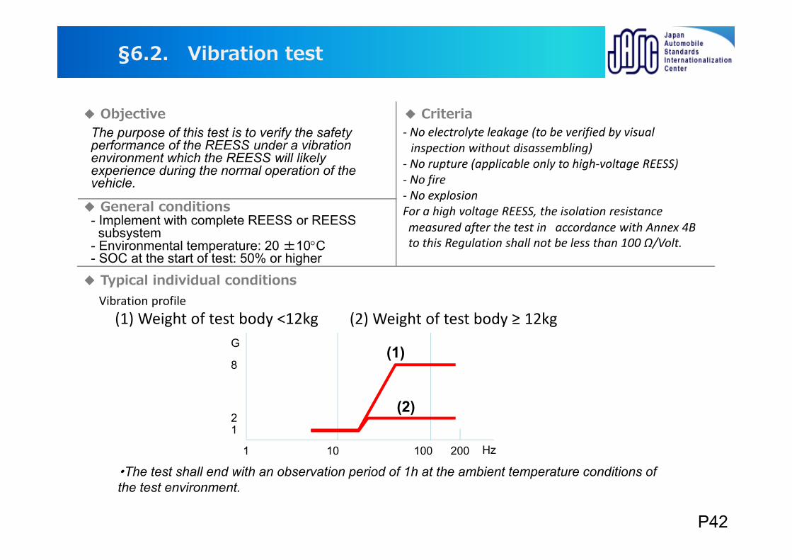
The purpose of this test is to verify the safety performance of the REESS under a vibration environment which the REESS will likely experience during the normal operation of the vehicle.
- Implement with complete REESS or REESS subsystem
- Environmental temperature: 20 ±10C- SOC at the start of test: 50% or higher
‐ No electrolyte leakage (to be verified by visual inspection without disassembling)
‐ No rupture (applicable only to high‐voltage REESS)‐ No fire‐ No explosionFor a high voltage REESS, the isolation resistancemeasured after the test in accordance with Annex 4B to this Regulation shall not be less than 100 Ω/Volt.
Vibration profile(1) Weight of test body <12kg (2) Weight of test body ≥ 12kg
1 10 100 200 Hz
12
8
G(1)
(2)
§6.2. Vibration test
Objective Criteria
General conditions
Typical individual conditions
・The test shall end with an observation period of 1h at the ambient temperature conditions of the test environment.
P42
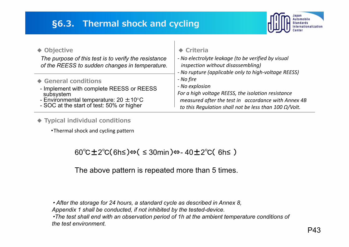
The purpose of this test is to verify the resistance of the REESS to sudden changes in temperature.
・Thermal shock and cycling pattern
60±2(6h≤)⇔( ≤ 30min)⇔- 40±2( 6h≤ )
The above pattern is repeated more than 5 times.
・ After the storage for 24 hours, a standard cycle as described in Annex 8,Appendix 1 shall be conducted, if not inhibited by the tested-device. ・The test shall end with an observation period of 1h at the ambient temperature conditions of the test environment.
§6.3. Thermal shock and cycling
‐ No electrolyte leakage (to be verified by visual inspection without disassembling)
‐ No rupture (applicable only to high‐voltage REESS)‐ No fire‐ No explosionFor a high voltage REESS, the isolation resistancemeasured after the test in accordance with Annex 4B to this Regulation shall not be less than 100 Ω/Volt.
- Implement with complete REESS or REESS subsystem
- Environmental temperature: 20 ±10C- SOC at the start of test: 50% or higher
Objective
General conditions
Criteria
Typical individual conditions
P43
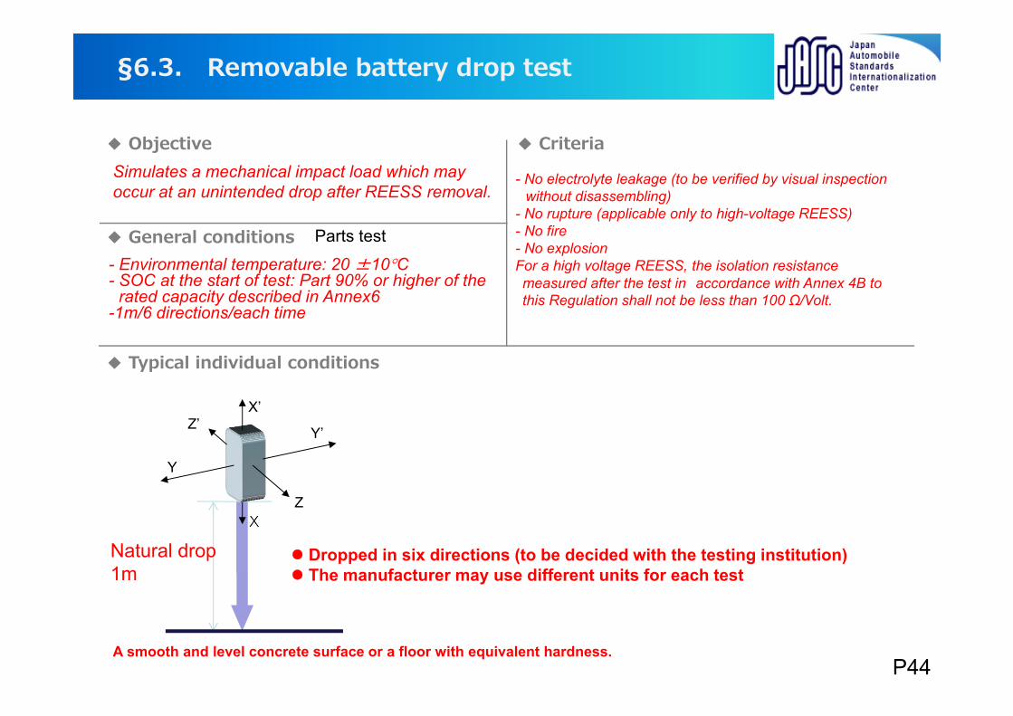
Removable battery drop test
Simulates a mechanical impact load which may occur at an unintended drop after REESS removal.
Parts test
Natural drop1m
A smooth and level concrete surface or a floor with equivalent hardness.
X
X’
Y
Y’Z’
Z
Dropped in six directions (to be decided with the testing institution) The manufacturer may use different units for each test
§6.3.
Objective Criteria
General conditions
Typical individual conditions
- Environmental temperature: 20 ±10C- SOC at the start of test: Part 90% or higher of the
rated capacity described in Annex6-1m/6 directions/each time
- No electrolyte leakage (to be verified by visual inspection without disassembling)
- No rupture (applicable only to high-voltage REESS)- No fire- No explosionFor a high voltage REESS, the isolation resistancemeasured after the test in accordance with Annex 4B to this Regulation shall not be less than 100 Ω/Volt.
P44
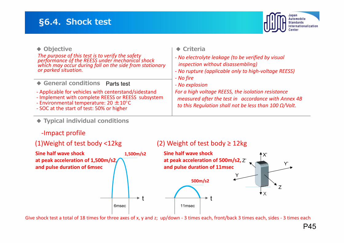
Shock test
The purpose of this test is to verify the safety performance of the REESS under mechanical shock which may occur during fall on the side from stationary or parked situation.
Parts test
‐Impact profile
Give shock test a total of 18 times for three axes of x, y and z; up/down ‐ 3 times each, front/back 3 times each, sides ‐ 3 times each
Sine half wave shock at peak acceleration of 1,500m/s2, and pulse duration of 6msec
6msec 11msect t
1,500m/s2
500m/s2
X
X’
Y
Y’Z’
Z
§6.4.
Objective Criteria
General conditions
Typical individual conditions
(1)Weight of test body <12kg (2) Weight of test body ≥ 12kg
‐ Applicable for vehicles with centerstand/sidestand‐ Implement with complete REESS or REESS subsystem‐ Environmental temperature: 20 ±10C‐ SOC at the start of test: 50% or higher
Sine half wave shock at peak acceleration of 500m/s2, and pulse duration of 11msec
‐ No electrolyte leakage (to be verified by visual inspection without disassembling)
‐ No rupture (applicable only to high‐voltage REESS)‐ No fire‐ No explosionFor a high voltage REESS, the isolation resistancemeasured after the test in accordance with Annex 4B to this Regulation shall not be less than 100 Ω/Volt.
P45
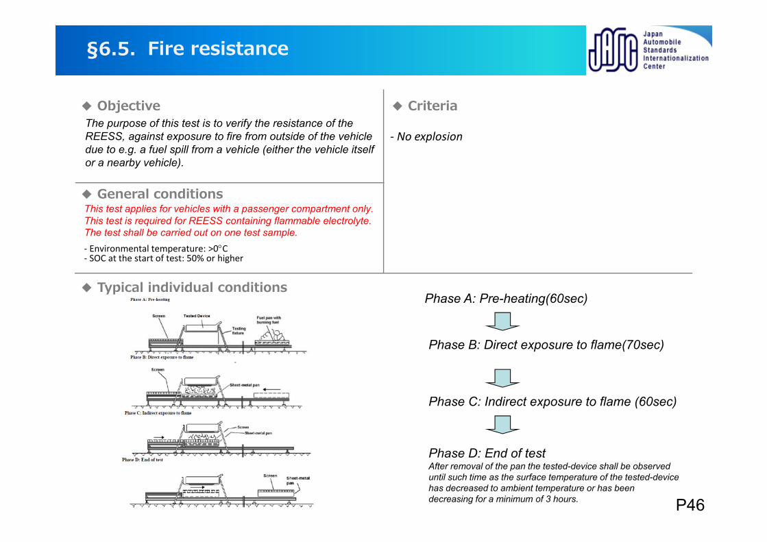
The purpose of this test is to verify the resistance of the REESS, against exposure to fire from outside of the vehicle due to e.g. a fuel spill from a vehicle (either the vehicle itself or a nearby vehicle).
This test applies for vehicles with a passenger compartment only. This test is required for REESS containing flammable electrolyte.The test shall be carried out on one test sample.
Phase A: Pre-heating(60sec)
Phase B: Direct exposure to flame(70sec)
Phase C: Indirect exposure to flame (60sec)
Phase D: End of testAfter removal of the pan the tested-device shall be observed until such time as the surface temperature of the tested-device has decreased to ambient temperature or has been decreasing for a minimum of 3 hours.
Objective Criteria
General conditions
‐ No explosion
Fire resistance§6.5.
‐ Environmental temperature: >0C‐ SOC at the start of test: 50% or higher
Typical individual conditions
P46
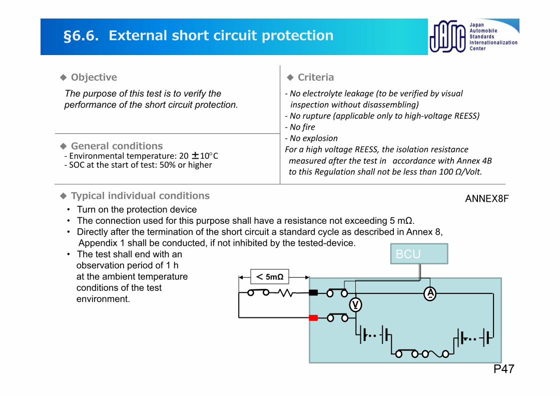
The purpose of this test is to verify the performance of the short circuit protection.
‐ Environmental temperature: 20 ±10C‐ SOC at the start of test: 50% or higher
・ Turn on the protection device・ The connection used for this purpose shall have a resistance not exceeding 5 mΩ.・ Directly after the termination of the short circuit a standard cycle as described in Annex 8,
Appendix 1 shall be conducted, if not inhibited by the tested-device.・ The test shall end with an
observation period of 1 h at the ambient temperature conditions of the test environment. V
・・・・・・
A
BCU
< 5mΩ
ANNEX8F
Objective
General conditions
Typical individual conditions
External short circuit protection§6.6.
‐ No electrolyte leakage (to be verified by visual inspection without disassembling)
‐ No rupture (applicable only to high‐voltage REESS)‐ No fire‐ No explosionFor a high voltage REESS, the isolation resistancemeasured after the test in accordance with Annex 4B to this Regulation shall not be less than 100 Ω/Volt.
Criteria
P47
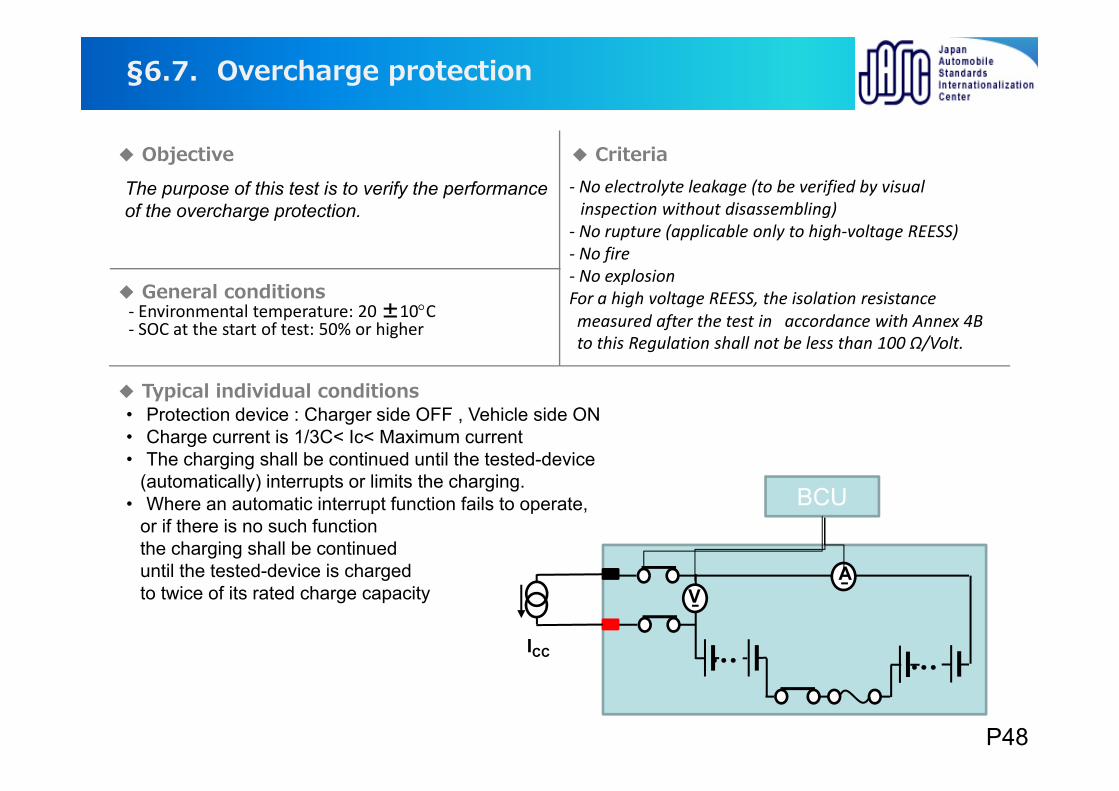
・ Protection device : Charger side OFF , Vehicle side ON・ Charge current is 1/3C< Ic< Maximum current・ The charging shall be continued until the tested-device
(automatically) interrupts or limits the charging.・ Where an automatic interrupt function fails to operate,
or if there is no such function the charging shall be continued until the tested-device is charged to twice of its rated charge capacity
The purpose of this test is to verify the performance of the overcharge protection.
Overcharge protection§6.7.
‐ No electrolyte leakage (to be verified by visual inspection without disassembling)
‐ No rupture (applicable only to high‐voltage REESS)‐ No fire‐ No explosionFor a high voltage REESS, the isolation resistancemeasured after the test in accordance with Annex 4B to this Regulation shall not be less than 100 Ω/Volt.
Objective
General conditions
Typical individual conditions
Criteria
‐ Environmental temperature: 20 ±10C‐ SOC at the start of test: 50% or higher
V
・・・・・・
A
BCU
ICC
P48
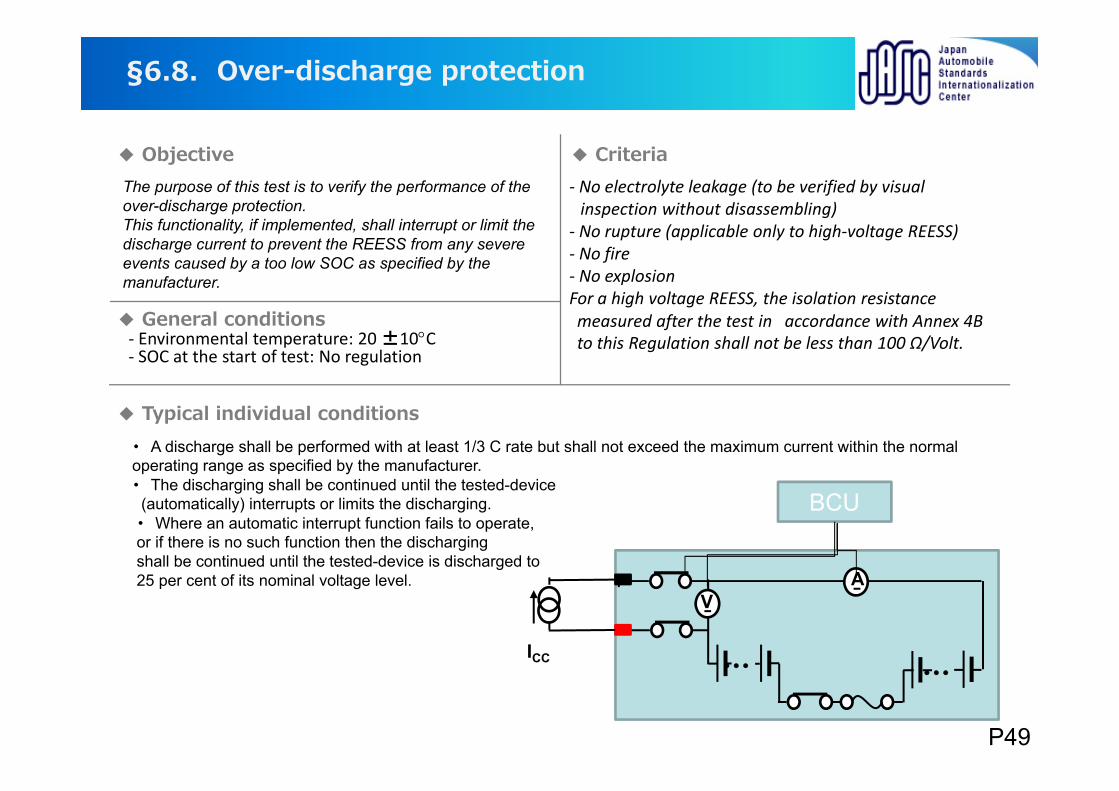
The purpose of this test is to verify the performance of the over-discharge protection.This functionality, if implemented, shall interrupt or limit the discharge current to prevent the REESS from any severe events caused by a too low SOC as specified by the manufacturer.
・ A discharge shall be performed with at least 1/3 C rate but shall not exceed the maximum current within the normal operating range as specified by the manufacturer.・ The discharging shall be continued until the tested-device
(automatically) interrupts or limits the discharging.・ Where an automatic interrupt function fails to operate, or if there is no such function then the discharging shall be continued until the tested-device is discharged to25 per cent of its nominal voltage level.
Over-discharge protection§6.8.
Objective
General conditions
Typical individual conditions
Criteria
‐ Environmental temperature: 20 ±10C‐ SOC at the start of test: No regulation
V
・・・・・・
A
BCU
ICC
‐ No electrolyte leakage (to be verified by visual inspection without disassembling)
‐ No rupture (applicable only to high‐voltage REESS)‐ No fire‐ No explosionFor a high voltage REESS, the isolation resistancemeasured after the test in accordance with Annex 4B to this Regulation shall not be less than 100 Ω/Volt.
P49
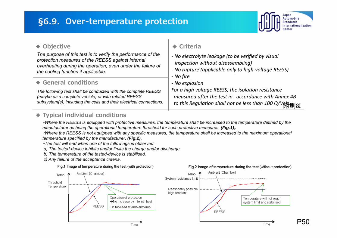
The purpose of this test is to verify the performance of the protection measures of the REESS against internal overheating during the operation, even under the failure of the cooling function if applicable.
・Where the REESS is equipped with protective measures, the temperature shall be increased to the temperature defined by the manufacturer as being the operational temperature threshold for such protective measures. (Fig.1)。・Where the REESS is not equipped with any specific measures, the temperature shall be increased to the maximum operational temperature specified by the manufacturer. (Fig.2)。・The test will end when one of the followings is observed:a) The tested-device inhibits and/or limits the charge and/or discharge.b) The temperature of the tested-device is stabilised.c) Any failure of the acceptance criteria.
附則8I
Over-temperature protection§6.9.
Objective
General conditions
Typical individual conditions
Criteria
The following test shall be conducted with the complete REESS (maybe as a complete vehicle) or with related REESS subsystem(s), including the cells and their electrical connections.
‐ No electrolyte leakage (to be verified by visual inspection without disassembling)
‐ No rupture (applicable only to high‐voltage REESS)‐ No fire‐ No explosionFor a high voltage REESS, the isolation resistancemeasured after the test in accordance with Annex 4B to this Regulation shall not be less than 100 Ω/Volt.
P50
Emission§6.10.
Objective Criteria
General conditions
Typical individual conditions
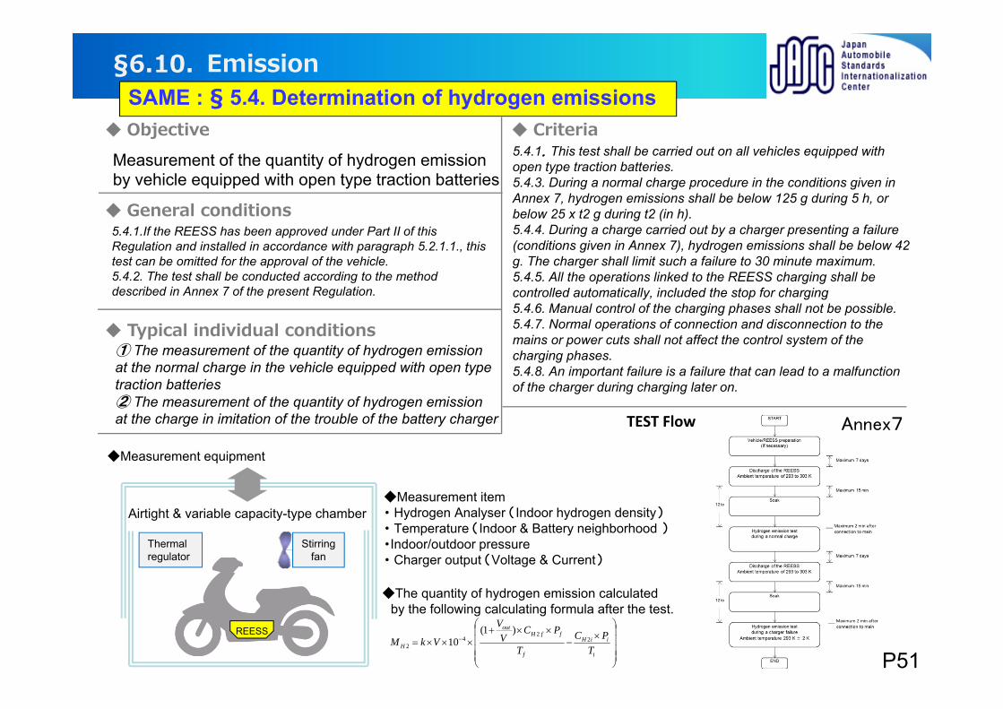
Measurement of the quantity of hydrogen emission by vehicle equipped with open type traction batteries
5.4.1.If the REESS has been approved under Part II of this Regulation and installed in accordance with paragraph 5.2.1.1., this test can be omitted for the approval of the vehicle.5.4.2. The test shall be conducted according to the method described in Annex 7 of the present Regulation.
5.4.1.This test shall be carried out on all vehicles equipped with open type traction batteries.5.4.3. During a normal charge procedure in the conditions given in Annex 7, hydrogen emissions shall be below 125 g during 5 h, or below 25 x t2 g during t2 (in h).5.4.4. During a charge carried out by a charger presenting a failure (conditions given in Annex 7), hydrogen emissions shall be below 42 g. The charger shall limit such a failure to 30 minute maximum.5.4.5. All the operations linked to the REESS charging shall be controlled automatically, included the stop for charging5.4.6. Manual control of the charging phases shall not be possible.5.4.7. Normal operations of connection and disconnection to the mains or power cuts shall not affect the control system of the charging phases.5.4.8. An important failure is a failure that can lead to a malfunction of the charger during charging later on.
① The measurement of the quantity of hydrogen emission at the normal charge in the vehicle equipped with open type traction batteries ② The measurement of the quantity of hydrogen emissionat the charge in imitation of the trouble of the battery charger TEST Flow
REESS
Airtight & variable capacity-type chamberMeasurement item・ Hydrogen Analyser (Indoor hydrogen density)・ Temperature (Indoor & Battery neighborhood )・Indoor/outdoor pressure・ Charger output (Voltage & Current)
Stirringfan
Measurement equipment
Thermal regulator
i
iiH
f
ffHout
H TPC
T
PCV
V
VkM 22
42
)1(10
The quantity of hydrogen emission calculated by the following calculating formula after the test.
Annex7
P51
SAME : § 5.4. Determination of hydrogen emissions

Thank you for your attention !
P52
Contents
Appendix
Introduction of e-PTW-related ISO/IEC
P53
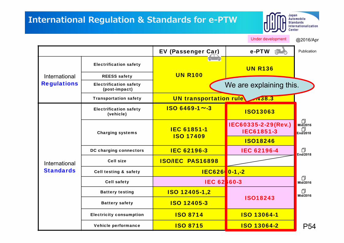
EV (Passenger Car) e-PTW
InternationalRegulations
Electrification safety
UN R100UN R136
REESS safety
Electrification safety(post-impact)
Transportation safety UN transportation rules UN38.3
International Standards
Electrification safety (vehicle)
ISO 6469-1~-3 ISO13063
Charging systems IEC 61851-1ISO 17409
IEC60335-2-29(Rev.)IEC61851-3ISO18246
DC charging connectors IEC 62196-3 IEC 62196-4Cell size ISO/IEC PAS16898
Cell testing & safety IEC62660-1,-2Cell safety IEC 62660-3
Battery testing ISO 12405-1,2ISO18243
Battery safety ISO 12405-3
Electricity consumption ISO 8714 ISO 13064-1
Vehicle performance ISO 8715 ISO 13064-2
International Regulation & Standards for e-PTW
Mid/2016
End/2018
End/2018
@2016/Apr
Mid/2016
Publication
Mid/2016
Under development
We are explaining this.
P54
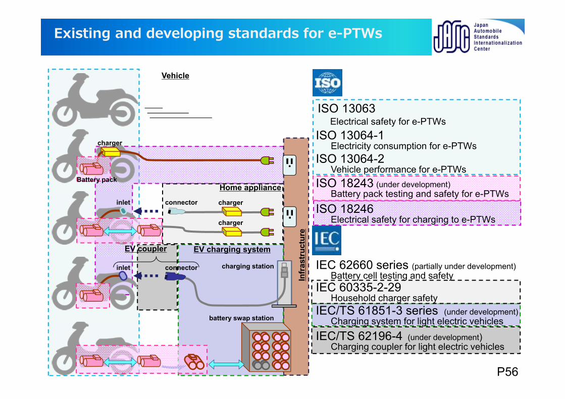
Existing and developing standards for e-PTWs
charger
battery swap station
charger
charging station
charger
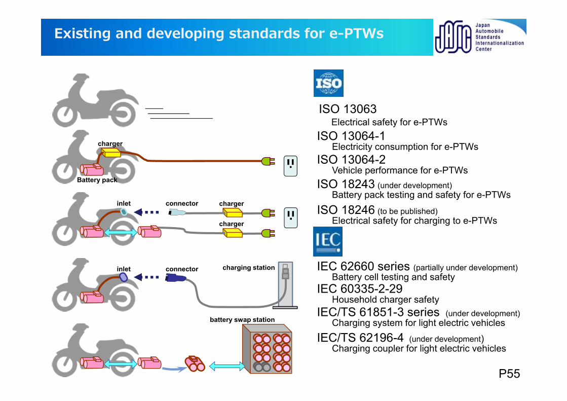
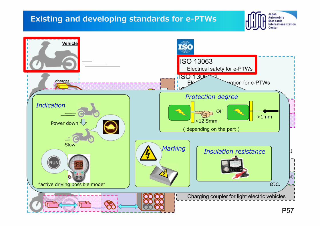
ISO 13063Electrical safety for e-PTWs
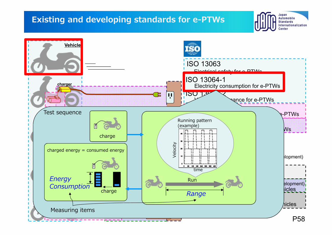
ISO 13064-1Electricity consumption for e-PTWs
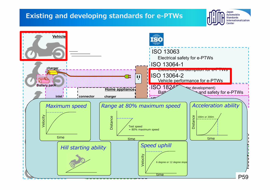
ISO 13064-2Vehicle performance for e-PTWs
ISO 18243 (under development)Battery pack testing and safety for e-PTWs
ISO 18246 (to be published)Electrical safety for charging to e-PTWs
IEC 62660 series (partially under development)Battery cell testing and safety
IEC 60335-2-29Household charger safety
IEC/TS 61851-3 series (under development)Charging system for light electric vehicles
IEC/TS 62196-4 (under development)Charging coupler for light electric vehicles
connectorinlet
connectorinlet
Battery pack
P55
charger
EV charging system
Home appliance
Infr
astr
uctu
re
battery swap station
charging station
charger
Vehicle
ISO 13063Electrical safety for e-PTWs
ISO 13064-1Electricity consumption for e-PTWs
ISO 13064-2Vehicle performance for e-PTWs
ISO 18243 (under development)Battery pack testing and safety for e-PTWs
ISO 18246Electrical safety for charging to e-PTWs
IEC 62660 series (partially under development)Battery cell testing and safety
IEC 60335-2-29Household charger safety
IEC/TS 61851-3 series (under development)Charging system for light electric vehicles
IEC/TS 62196-4 (under development)Charging coupler for light electric vehicles
connector
EV coupler
inlet
connectorinlet
Existing and developing standards for e-PTWs
charger
Battery pack
P56
charger
EV charging system
Home appliance
Infr
astr
uctu
re
battery swap station
charger
charging station
charger
Vehicle
ISO 13063Electrical safety for e-PTWs
ISO 13064-1Electricity consumption for e-PTWs
ISO 13064-2Vehicle performance for e-PTWs
ISO 18243 (under development)Battery pack testing and safety for e-PTWs
ISO 18246 (to be published)Electrical safety for charging to e-PTWs
IEC 62660 series (partially under development)Battery cell testing and safety
IEC 60335-2-29Household charger safety
IEC/TS 61851-3 series (under development)Charging system for light electric vehicles
IEC/TS 62196-4 (under development)Charging coupler for light electric vehicles
connector
EV coupler
inlet
connectorinlet
Existing and developing standards for e-PTWs
etc.“active driving possible mode”
Slow
Power down
Insulation resistance
Indication
Marking
>12.5mm>1mm
or
( depending on the part )
Protection degree
P57
charger
EV charging system
Home appliance
Infr
astr
uctu
re
battery swap station
charger
charging station
charger
ISO 13063Electrical safety for e-PTWs
ISO 13064-1Electricity consumption for e-PTWs
ISO 13064-2Vehicle performance for e-PTWs
ISO 18243 (under development)Battery pack testing and safety for e-PTWs
ISO 18246 (to be published)Electrical safety for charging to e-PTWs
IEC 62660 series (partially under development)Battery cell testing and safety
IEC 60335-2-29Household charger safety
IEC/TS 61851-3 series (under development)Charging system for light electric vehicles
IEC/TS 62196-4 (under development)Charging coupler for light electric vehicles
connector
EV coupler
inlet
connectorinlet
Existing and developing standards for e-PTWs
RangeRange
Running pattern (example)Running pattern (example)
timetimeVe
loci
tyVe
loci
tyRunRun
Range
Running pattern (example)
timeVe
loci
tyRun
Test sequence
Measuring items
charge
EnergyConsumption
charged energy = consumed energy
charge
Vehicle
P58
charger
EV charging system
Home appliance
Infr
astr
uctu
re
battery swap station
charger
charging station
charger
ISO 13063Electrical safety for e-PTWs
ISO 13064-1Electricity consumption for e-PTWs
ISO 13064-2Vehicle performance for e-PTWs
ISO 18243 (under development)Battery pack testing and safety for e-PTWs
ISO 18246 (to be published)Electrical safety for charging to e-PTWs
IEC 62660 series (partially under development)Battery cell testing and safety
IEC 60335-2-29Household charger safety
IEC/TS 61851-3 series (under development)Charging system for light electric vehicles
IEC/TS 62196-4 (under development)Charging coupler for light electric vehicles
connector
EV coupler
inlet
connectorinlet
Battery pack
Existing and developing standards for e-PTWs
time
Dist
ance
Test speed = 80% maximum speed
Range at 80% maximum speed
time
Velo
city
Maximum speed
time
Dist
ance
Acceleration ability
100m or 200m
Hill starting ability
time
Velo
city
Speed uphill
6 degree or 12 degree slope
Vehicle
P59
charger
EV charging system
Home appliance
Infr
astr
uctu
re
battery swap station
charger
charging station
charger
ISO 13063Electrical safety for e-PTWs
ISO 13064-1Electricity consumption for e-PTWs
ISO 13064-2Vehicle performance for e-PTWs
ISO 18243 (under development)Battery pack testing and safety for e-PTWs
ISO 18246 (to be published)Electrical safety for charging to e-PTWs
IEC 62660 series (partially under development)Battery cell testing and safety
IEC 60335-2-29Household charger safety
IEC/TS 61851-3 series (under development)Charging system for light electric vehicles
IEC/TS 62196-4 (under development)Charging coupler for light electric vehicles
connector
EV coupler
inlet
connectorinlet
Battery pack
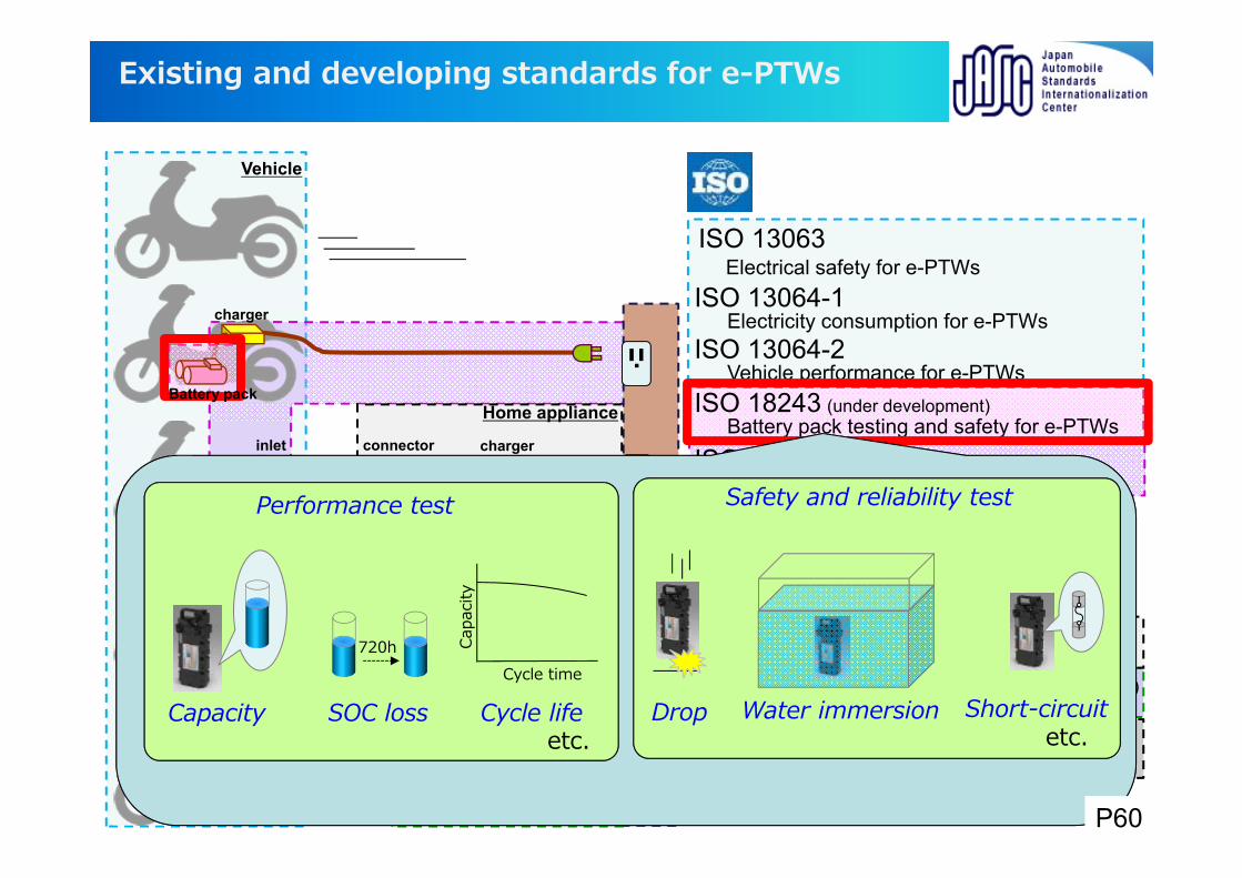
Existing and developing standards for e-PTWs
Safety and reliability test
Dropetc.
Cycle lifeCapacity
Performance test
etc.Water immersion
Cycle time
Capa
city
720h
SOC loss Short-circuit
Vehicle
P60
charger
EV charging system
Home appliance
Infr
astr
uctu
re
battery swap station
charger
charging station
charger
ISO 13063Electrical safety for e-PTWs
ISO 13064-1Electricity consumption for e-PTWs
ISO 13064-2Vehicle performance for e-PTWs
ISO 18243 (under development)Battery pack testing and safety for e-PTWs
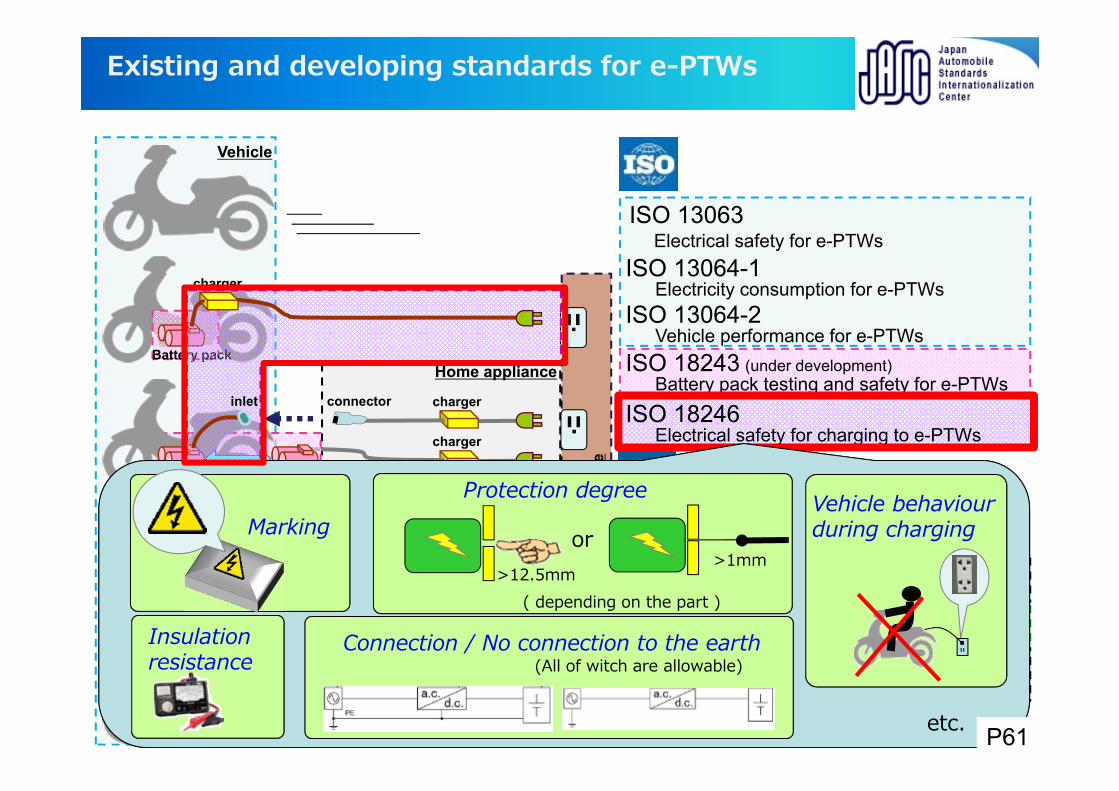
ISO 18246Electrical safety for charging to e-PTWs
IEC 62660 series (partially under development)Battery cell testing and safety
IEC 60335-2-29Household charger safety
IEC/TS 61851-3 series (under development)Charging system for light electric vehicles
IEC/TS 62196-4 (under development)Charging coupler for light electric vehicles
connector
EV coupler
connectorinlet
Existing and developing standards for e-PTWs
Battery pack
>12.5mm>1mm
or
( depending on the part )
Protection degree Vehicle behaviour during chargingMarking
inlet
etc.
Insulation resistance
Vehicle
Connection / No connection to the earth (All of witch are allowable)
P61
EV charging system
Infr
astr
uctu
re
battery swap station
charger
charging station
Vehicle
NOTEBattery cells are treated in IEC TC 21.
battery pack ISO 13063Electrical safety for e-PTWs
ISO 13064-1Electricity consumption for e-PTWs
ISO 13064-2Vehicle performance for e-PTWs
ISO 18243 (under development)Battery pack testing and safety for e-PTWs
ISO 18246 (to be published)Electrical safety for charging to e-PTWs
IEC 62660 series (partially under development)Battery cell testing and safety
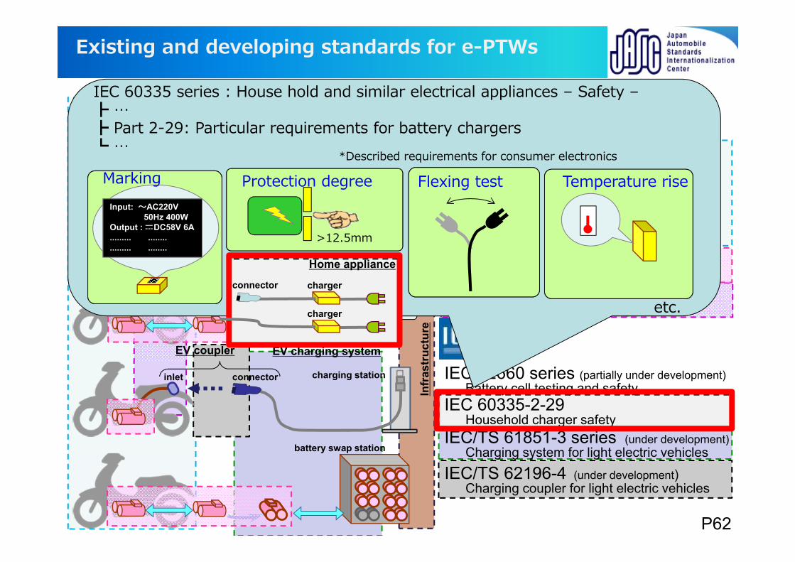
IEC 60335-2-29Household charger safety
IEC/TS 61851-3 series (under development)Charging system for light electric vehicles
IEC/TS 62196-4 (under development)Charging coupler for light electric vehicles
EV coupler
inlet
connectorinlet
charger
Home appliance
charger
connector
Existing and developing standards for e-PTWs
IEC 60335 series : House hold and similar electrical appliances – Safety – … Part 2-29: Particular requirements for battery chargers …
*Described requirements for consumer electronics
etc.
>12.5mm
Temperature riseFlexing test Protection degreeMarkingInput: 〜AC220V
50Hz 400WOutput : DC58V 6A......... ................. ........
P62
charger
Home appliance
Infr
astr
uctu
re
charger
charger
battery pack ISO 13063Electrical safety for e-PTWs
ISO 13064-1Electricity consumption for e-PTWs
ISO 13064-2Vehicle performance for e-PTWs
ISO 18243 (under development)Battery pack testing and safety for e-PTWs
ISO 18246 (to be published)Electrical safety for charging to e-PTWs
IEC 62660 series (partially under development)Battery cell testing and safety
IEC 60335-2-29Household charger safety
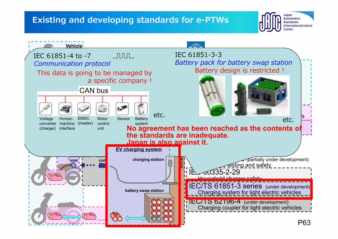
IEC/TS 61851-3 series (under development)Charging system for light electric vehicles
IEC/TS 62196-4 (under development)Charging coupler for light electric vehicles
connector
EV coupler
inlet
connectorinlet
EV charging system
battery swap station
charging station
Existing and developing standards for e-PTWs
No agreement has been reached as the contents of the standards are inadequate.Japan is also against it.
Voltage converter(charger)
Human machine interface
Motor control unit
Sensor Battery system
CAN bus
EMSC(master)
Battery design is restricted !
IEC 61851-3-3Battery pack for battery swap station
IEC 61851-4 to -7Communication protocolThis data is going to be managed by
a specific company !
etc.etc.
Vehicle
P63
Vehicle
charger
EV charging system
Home appliance
Infr
astr
uctu
re
battery swap station
charger
charging station
charger
battery pack ISO 13063Electrical safety for e-PTWs
ISO 13064-1Electricity consumption for e-PTWs
ISO 13064-2Vehicle performance for e-PTWs
ISO 18243 (under development)Battery pack testing and safety for e-PTWs
ISO 18246 (to be published)Electrical safety for charging to e-PTWs
IEC 62660 series (partially under development)Battery cell testing and safety
IEC 60335-2-29Household charger safety
IEC/TS 61851-3 series (under development)Charging system for light electric vehicles
IEC/TS 62196-4 (under development)Charging coupler for light electric vehicles
connectorinlet
EV coupler
connectorinlet
Existing and developing standards for e-PTWs
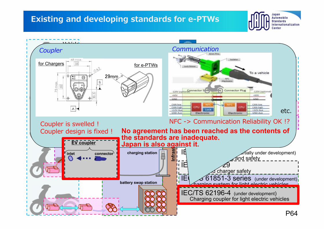
Coupler is swelled !Coupler design is fixed !
NFC -> Communication Reliability OK !?
Coupler Communication
etc.
29mm
for e-PTWsfor Chargers
No agreement has been reached as the contents of the standards are inadequate.Japan is also against it.
P64
P65
Terima Kasih banyah
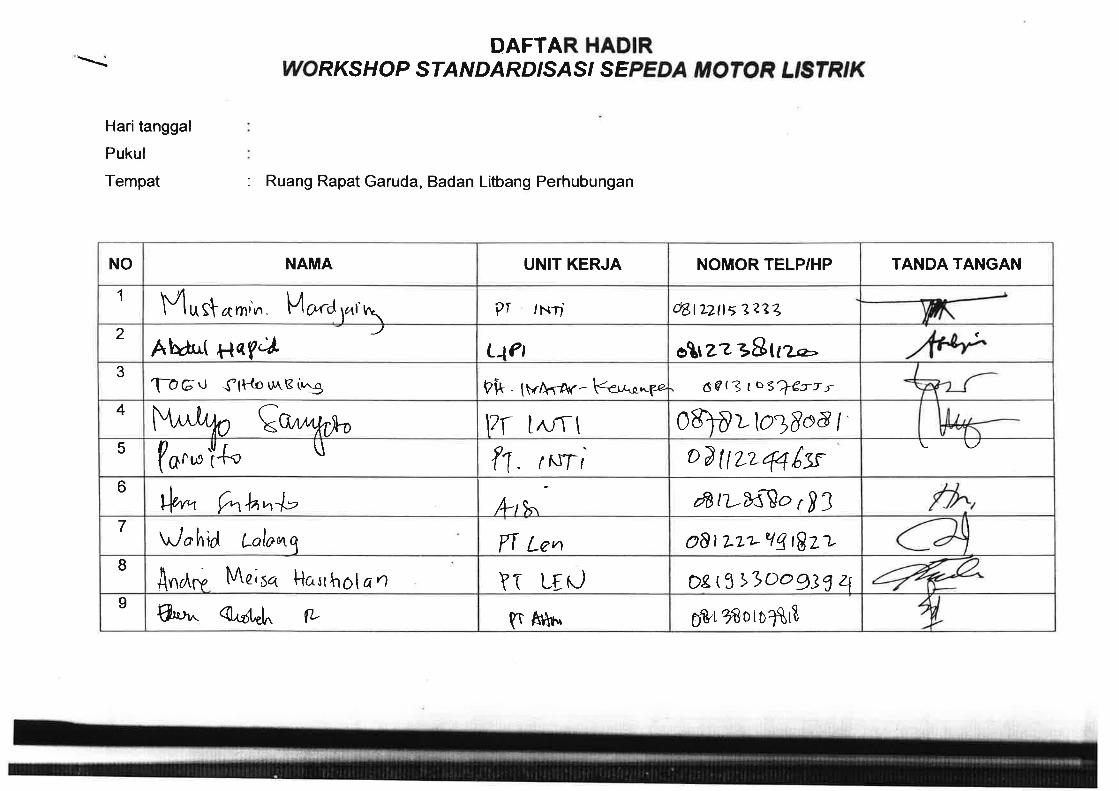
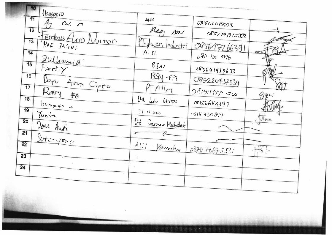
第 44 回アジア専門家会議(R136)報告
2016/6/23 修正
(案)2016/5/25
日時:2016 年 5 月 24 日(火)9:00~12:00
場所:インドネシア・ジャカルタ Research and Development Center of Land & Railway Transport
Ministry of Transportation 3F 会議室
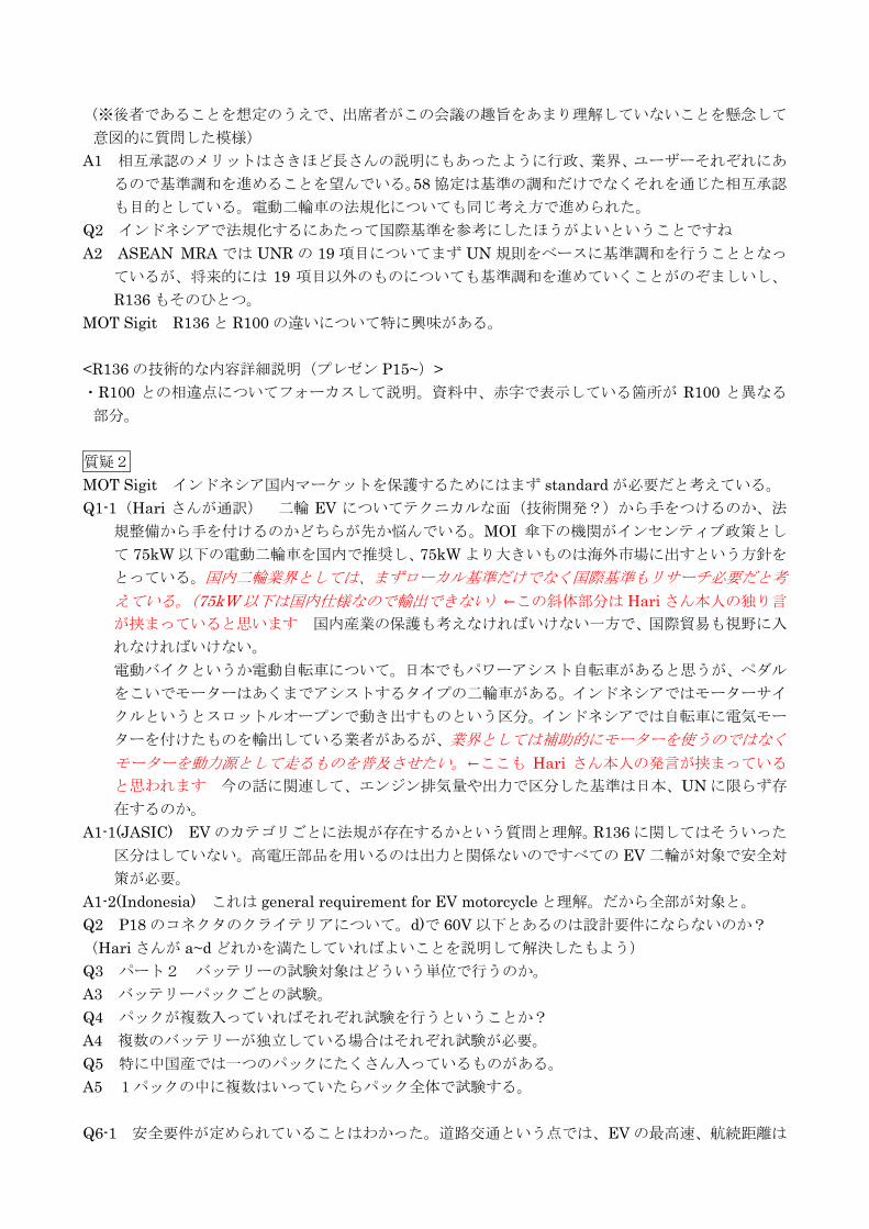
出席者:Mr. Sigit Irfansyah, Director for Road Transport and Railway R&D Center, MOT
Mr. Mr. Yok Suprobo, Road Transport and Railway R&D Center, MOT ほか MOT、MOI、AISI 総勢 20 名程度、別紙参照
(日本)長(ホンダ・JASIC)、是則(JASIC ジャカルタ)、戸羽(JASIC)
概要
・冒頭、Director for Road Transport and Railway R&D Center の Mr. Sigit Irfansyah から歓迎の挨
拶。
・JASIC ジャカルタ事務所長の是則より、このような機会を設けてくれたことに感謝。R136 は国連で
1958 協定のもとに合意された電動二輪車の国際基準。日本はこの協定に加盟しており R136 について
も採用準備を進めているところ。今日は R136 の理解を深める場としたい。
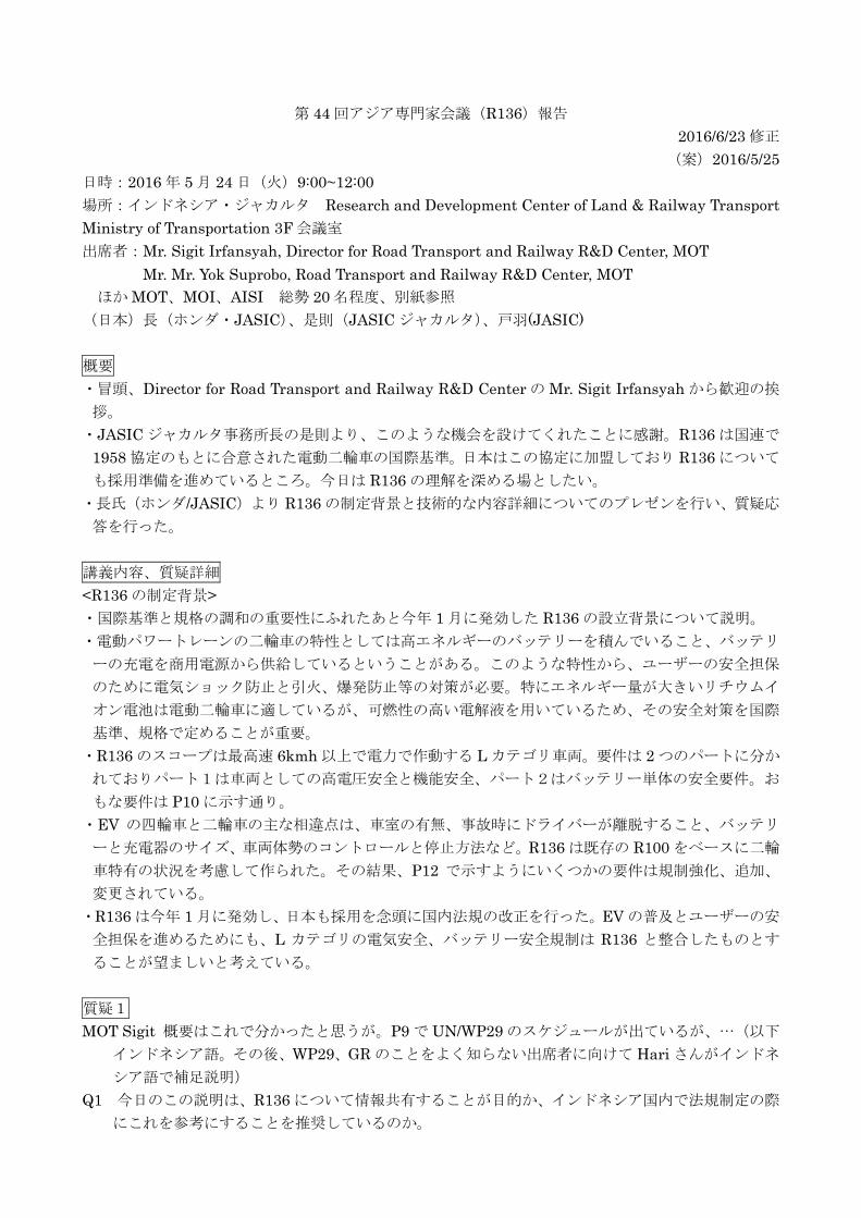
・長氏(ホンダ/JASIC)より R136 の制定背景と技術的な内容詳細についてのプレゼンを行い、質疑応
答を行った。
講義内容、質疑詳細
<R136 の制定背景>
・国際基準と規格の調和の重要性にふれたあと今年 1 月に発効した R136 の設立背景について説明。
・電動パワートレーンの二輪車の特性としては高エネルギーのバッテリーを積んでいること、バッテリ
ーの充電を商用電源から供給しているということがある。このような特性から、ユーザーの安全担保
のために電気ショック防止と引火、爆発防止等の対策が必要。特にエネルギー量が大きいリチウムイ
オン電池は電動二輪車に適しているが、可燃性の高い電解液を用いているため、その安全対策を国際
基準、規格で定めることが重要。
・R136 のスコープは最高速 6kmh 以上で電力で作動する L カテゴリ車両。要件は 2 つのパートに分か
れておりパート1は車両としての高電圧安全と機能安全、パート2はバッテリー単体の安全要件。お
もな要件は P10 に示す通り。
・EV の四輪車と二輪車の主な相違点は、車室の有無、事故時にドライバーが離脱すること、バッテリ
ーと充電器のサイズ、車両体勢のコントロールと停止方法など。R136 は既存の R100 をベースに二輪
車特有の状況を考慮して作られた。その結果、P12 で示すようにいくつかの要件は規制強化、追加、
変更されている。
・R136 は今年 1 月に発効し、日本も採用を念頭に国内法規の改正を行った。EV の普及とユーザーの安
全担保を進めるためにも、L カテゴリの電気安全、バッテリー安全規制は R136 と整合したものとす
ることが望ましいと考えている。
質疑1
MOT Sigit 概要はこれで分かったと思うが。P9 で UN/WP29 のスケジュールが出ているが、…(以下
インドネシア語。その後、WP29、GR のことをよく知らない出席者に向けて Hari さんがインドネ
シア語で補足説明)
Q1 今日のこの説明は、R136 について情報共有することが目的か、インドネシア国内で法規制定の際
にこれを参考にすることを推奨しているのか。
(※後者であることを想定のうえで、出席者がこの会議の趣旨をあまり理解していないことを懸念して
意図的に質問した模様)
A1 相互承認のメリットはさきほど長さんの説明にもあったように行政、業界、ユーザーそれぞれにあ
るので基準調和を進めることを望んでいる。58 協定は基準の調和だけでなくそれを通じた相互承認
も目的としている。電動二輪車の法規化についても同じ考え方で進められた。
Q2 インドネシアで法規化するにあたって国際基準を参考にしたほうがよいということですね
A2 ASEAN MRA では UNR の 19 項目についてまず UN 規則をベースに基準調和を行うこととなっ
ているが、将来的には 19 項目以外のものについても基準調和を進めていくことがのぞましいし、
R136 もそのひとつ。
MOT Sigit R136 と R100 の違いについて特に興味がある。
<R136 の技術的な内容詳細説明(プレゼン P15~)>
・R100 との相違点についてフォーカスして説明。資料中、赤字で表示している箇所が R100 と異なる
部分。
質疑2
MOT Sigit インドネシア国内マーケットを保護するためにはまず standard が必要だと考えている。
Q1-1(Hari さんが通訳) 二輪 EV についてテクニカルな面(技術開発?)から手をつけるのか、法
規整備から手を付けるのかどちらが先か悩んでいる。MOI 傘下の機関がインセンティブ政策とし
て 75kW 以下の電動二輪車を国内で推奨し、75kW より大きいものは海外市場に出すという方針を
とっている。国内二輪業界としては、まずローカル基準だけでなく国際基準もリサーチ必要だと考
えている。(75kW 以下は国内仕様なので輸出できない)←この斜体部分は Hari さん本人の独り言
が挟まっていると思います 国内産業の保護も考えなければいけない一方で、国際貿易も視野に入
れなければいけない。
電動バイクというか電動自転車について。日本でもパワーアシスト自転車があると思うが、ペダル
をこいでモーターはあくまでアシストするタイプの二輪車がある。インドネシアではモーターサイ
クルというとスロットルオープンで動き出すものという区分。インドネシアでは自転車に電気モー
ターを付けたものを輸出している業者があるが、業界としては補助的にモーターを使うのではなく
モーターを動力源として走るものを普及させたい。←ここも Hari さん本人の発言が挟まっている
と思われます 今の話に関連して、エンジン排気量や出力で区分した基準は日本、UN に限らず存
在するのか。
A1-1(JASIC) EV のカテゴリごとに法規が存在するかという質問と理解。R136 に関してはそういった
区分はしていない。高電圧部品を用いるのは出力と関係ないのですべての EV 二輪が対象で安全対
策が必要。
A1-2(Indonesia) これは general requirement for EV motorcycle と理解。だから全部が対象と。
Q2 P18 のコネクタのクライテリアについて。d)で 60V 以下とあるのは設計要件にならないのか?
(Hari さんが a~d どれかを満たしていればよいことを説明して解決したもよう)
Q3 パート2 バッテリーの試験対象はどういう単位で行うのか。
A3 バッテリーパックごとの試験。
Q4 パックが複数入っていればそれぞれ試験を行うということか?
A4 複数のバッテリーが独立している場合はそれぞれ試験が必要。
Q5 特に中国産では一つのパックにたくさん入っているものがある。
A5 1パックの中に複数はいっていたらパック全体で試験する。
Q6-1 安全要件が定められていることはわかった。道路交通という点では、EV の最高速、航続距離は
定められているのか。
Q6-2 電動二輪の問題は、重いこと(→航続距離に影響)、価格が高いことも壁。 A6 最高速については日本では警察が規定している。日本では二輪車のサイズにより30km/h、50km/h、
100km/h で区分している。航続距離の要件はなく、測定方法だけ定めている。航続距離はユーザー
がニーズに応じて商品を選ぶ要素の一つであり規制はしていない。
MOT Sigit 日本からインドネシアに対して何か質問があればどうぞ。
Q1(JASIC) インドネシアで電動二輪のインセンティブを考えていると聞いているがどういう内容か。
A1-1(Indonesia) 現状まったく規制がないが、インセンティブによりバッテリーの開発推進につながる
などの効果を期待している。
A1-2(Indonesia, Hari さん通訳) ある団体が強い要望をだしているが、MOI としてどういうインセン
ティブを行えばいいか考えているところ。
Q2(Indonesia) 日本ではそういう政策はあるのか?
A2&Q3(JASIC) 過去にはあった。新型電動二輪車に対する補助金があった。(Q3)もうひとつ質問だが、
日本では電動アシスト二輪は自転車とみなしていて免許もヘルメットも不要。もしインドネシアで
電動二輪を motorcycle に含めるなら免許やヘルメットは必要になるのか?
A3-1(Indonesia) それを業界としては危惧している。モールなどに行くとかなりの数の電動アシスト車
を見かける。ペダルをこがなければいけないタイプの pedal-electric というものだが。現状 MOT
では motor vehicle はペダルをこがなくてよい、スロットルオープンで動き出すものを指している。 A3-2(JASIC) 日本ではこがなくていいものは motorcycle に分類される。スロットルオープンだけで動
くものは特に高齢者や子供に対し危険。免許、ヘルメットも必要。ブレーキ、ミラー、ランプなど
の要件も定めた。
Q4(JASIC) 電動二輪車は中国産なども含めてインドネシアでは市場でどのくらい出回っているの
か?
A4-1 非常に少ない。ほとんどないといってもいいくらい。2008 年のジュネーブモーターショーで関
係者に会って話をしたが。市場台数が少ない理由の一つはペダルすらないスクーターのような見た
目のものもあるので。将来どうなるかはわからないが。日本ではどうか?
A4-2(JASIC) 同じように、日本でも電動二輪車は極めて少ないです。
A4-3(Indonesia) 中国では電動二輪自転車の類が非常に多い。
A4-4(JASIC) ベトナムには中国産の電動自転車が多いと聞いている。
A4-5(Indonesia) インドネシアに中国産の車両が入ってくる前に法規制を急ぐ必要があると思ってい
る。
A4-6(JASIC) ベトナムでは中国からたくさん輸入していると聞いた。静かなことなど原因で事故が多
く問題になっていると。バッテリーのリサイクルも問題になっていると聞いている。
Closing
MOT Sagit 今日は詳細な説明で R136 の内容の理解が深まったと思う。
AISI Hari まずは情報を共有して国内法規化の検討を進めたい。
MOT Sagit 今後も MOT、MOI から JASIC に問い合わせをするかもしれないのでその際は協力をお
願いしたい。
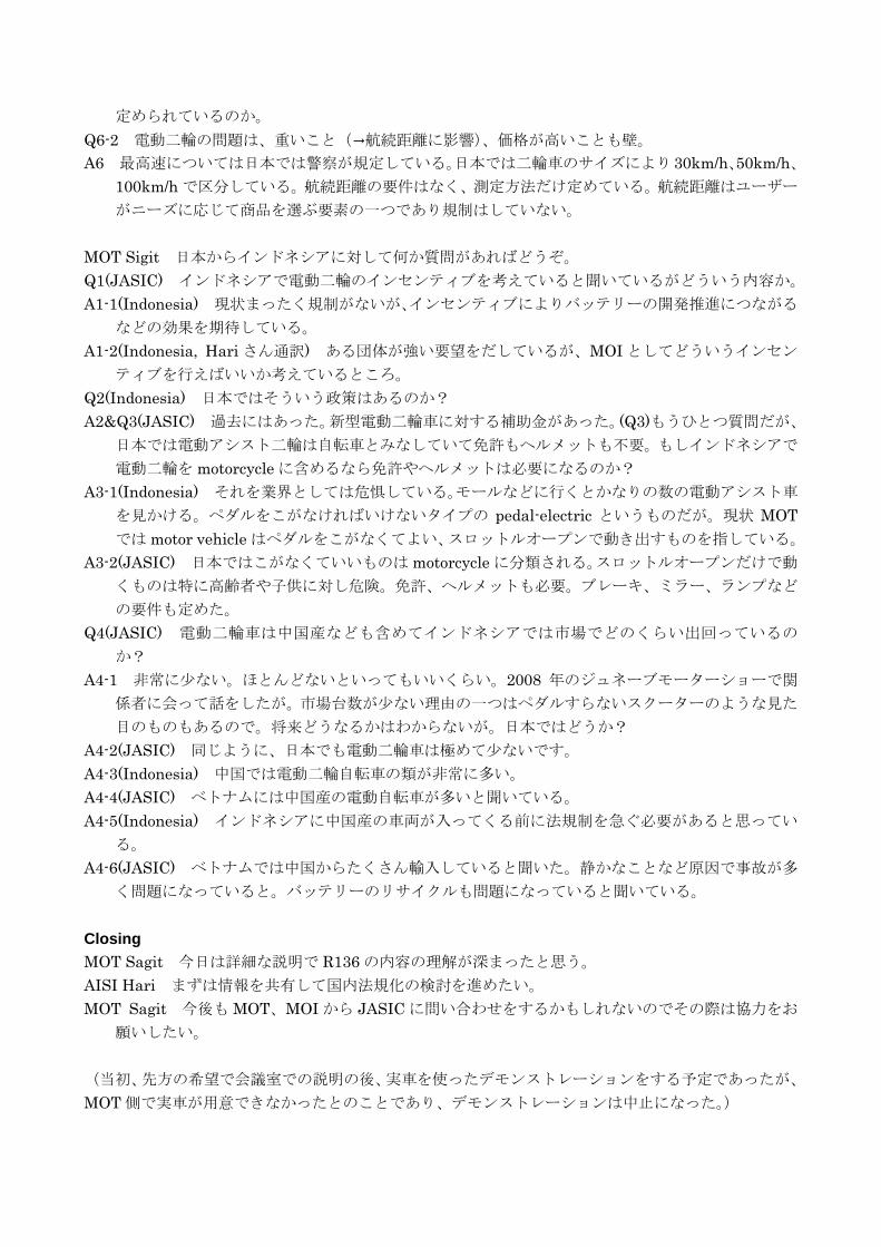
(当初、先方の希望で会議室での説明の後、実車を使ったデモンストレーションをする予定であったが、
MOT 側で実車が用意できなかったとのことであり、デモンストレーションは中止になった。)
以上