Embed Size (px)
DESCRIPTION
fire detection
Citation preview
Version 2.7 1
Remote Display and
Control Panel
RDCP
Installation Manual
Article-No. 32118 For-Software version or newer: 4ME_08_xx resp. 3ME_08_xx 4SE_08_xx resp. 3SE_08_xx

Hallo Remote Display and Control Panel
Version 2.7 2
detectomat GmbH Headquarter: Phone: +49 (0) 4102-2114-60 An der Strusbek 5 Fax: +49 (0) 4102-2114-670 D – 22926 Ahrensburg Germany Hotline: Please see www.detectomat.com Manual no.: 55977 Version 2.7 - 24.03.2010
15 Remote Display and Control Panel
Version 2.7 3
Index
1 Manual purpose and structure .............................................................5 1.1 Purpose of the installation manual ....................................................................................5 1.2 Structure of the manual ....................................................................................................5 2 General safety notes .............................................................................6 2.1 Intended application .........................................................................................................6 2.2 Requirements for the operating company .........................................................................6 3 Software changes and improvements .................................................7 4 In General ..............................................................................................7 4.1 RDCP-Software version ....................................................................................................7 4.2 Indication of a Bitbus fault in the display...........................................................................8 4.3 Specification of the INTEL-BITBUS-Network......................................................................9 4.4 Power supply of the RDCP ..............................................................................................10 5 Function description ...........................................................................10 6 Operation-/Service mode....................................................................10 7 LCD-Display.........................................................................................10 7.1 Structure of the LCD-Display: .........................................................................................11 7.2 Indication of system fault................................................................................................12 7.3 Current counters in the 4th display line:...........................................................................12 8 LED-Display .........................................................................................13 9 Access control.....................................................................................14 10 Internal and external buzzer...............................................................15 11 Lamp test.............................................................................................15 12 Transmission unit in a network..........................................................16 12.1 In general .......................................................................................................................16 12.2 TU at the Master-RDCP without an emergency path........................................................16 12.3 TU at the Master-RDCP with an emergency path ............................................................17 12.4 TU at the sub-panels ......................................................................................................17 13 Delay On/Off ........................................................................................18 14 Ext. Warning On / Off ..........................................................................18 15 Revision button (one-man-walk test) ................................................19 16 Master Reset .......................................................................................20 17 Enable-/disable detectors-/ zones.....................................................20 17.1 Enabling/disabling addressable detectors .......................................................................21 17.2 En-/Disabling conventional zones-/ lines ........................................................................21 17.3 Enabling/disabling outputs..............................................................................................22 18 Programming of the RDCP..................................................................23 18.1 Menu "Print Menu" (Input 0) ...........................................................................................23
18.1.1 Zone-LEDs ........................................................................................................24 18.1.2 System parameter .............................................................................................24 18.1.3 Bitbus node .......................................................................................................25 18.1.4 Print Buffer........................................................................................................25
18.2 Menu "Set Time" (Input 1) ..............................................................................................26 18.3 Menu "Diagnostics" (Input 2)..........................................................................................26
Version 2.7 4
18.3.1 Print Det.-Stats. (Input 0) ...................................................................................27 18.3.2 Show Det.-Stats. (Input 1) .................................................................................28 18.3.3 Detector test (Input 2)........................................................................................29 18.3.4 Message Buffer (Input 3) ...................................................................................29 18.3.5 BB Components (Input 4) ...................................................................................30 18.3.6 Node status (Input 5) .........................................................................................30 18.3.7 Reset-Status (Input 6)........................................................................................31
18.4 Menu "Alarm counter" (Input 3) ......................................................................................31 18.5 Menu "System Parameters" (Input 4)..............................................................................31
18.5.1 Menu "RDCP-Organisation" (Input 0) .................................................................31 18.5.1.1 Zone-LEDs ..........................................................................................32 18.5.1.2 Sector selection..................................................................................32 18.5.1.3 Detector zone Offset............................................................................33
18.5.2 Menu "Parameter" (Input 1) ..............................................................................34 18.5.3 Menu "Fault-Reset" (Input 2).............................................................................37 18.5.4 Menu "Custom Text Init." (Input 3) ....................................................................37 18.5.5 Menu "Parameter init" (Input 4).........................................................................37 18.5.6 Menu "Delete Buffer" (Input 5) ..........................................................................38 18.5.7 Menu "Read Nodes" (Input 6) ............................................................................38
18.6 Menu "Software-Version" (Input 5) .................................................................................38 19 Accessories .........................................................................................39 19.1 RDCP-LED-Interface (Art. 30128) incl. Bitbus-CPU and flat cable adapter .......................39 19.2 Bitbus CPU (Order no. 30119) .........................................................................................39 19.3 Bitbus-Repeater .............................................................................................................40
19.3.1 In general ..........................................................................................................40 19.3.2 Scope of delivery...............................................................................................40 19.3.3 Repeater circuit points.......................................................................................40 19.3.4 Power supply.....................................................................................................41 19.3.5 LED meanings ...................................................................................................41 19.3.6 Technical Data ..................................................................................................41
19.4 Bitbus-PC interface options ............................................................................................42 20 Assembly instructions ........................................................................42 20.1 RDCP in housing.............................................................................................................42 20.2 ABF 19“-fitting version (Order-No. 32119) ......................................................................42 20.3 Power supply..................................................................................................................42 21 Start up................................................................................................43 22 Fault details.........................................................................................44 22.1 Fault detail: ”Flt: Checksum Ram” ..................................................................................44 22.2 Fault detail: ”Flt: Main CPU” ...........................................................................................45 22.3 Fault detail: “Buffer overrun” ..........................................................................................45 23 Properties of relays and OC-outputs ..................................................46 23.1 Table of relays and OC-outputs.......................................................................................46 23.2 Output fault Bitbus..........................................................................................................46 24 Notes for the operation of the detect 3004 (plus) in a network........47 25 Example of a BitBus/optic fibre wiring ..............................................49
15 Remote Display and Control Panel
Version 2.7 5
1 Manual purpose and structure
1.1 Purpose of the installation manual This instruction manual applies to technically qualified users who have been or will be trained in
the operation of the Remote Display and Control Panel (RDCP).
As an operator and/or user you are obligated to read and understand this manual in its entirety
before proceeding. It contains relevant information on the operation, installation and maintenance
of the RDCP. It will help you to operate the panel safely and efficiently.
1.2 Structure of the manual The following conventions are used in this installation manual:
• Listings contain information (i.e. no work steps)
• Numbered listings contain a sequence of work steps or hierarchically ordered information
• Text inside quotation marks indicates a menu selection
• Key commands are shown in square brackets, i.e. [Reset]
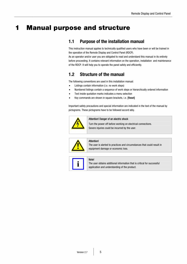
Important safety precautions and special information are indicated in the text of the manual by
pictograms. These pictograms have to be followed accord ably.
Attention! Danger of an electric shock
Turn the power off before working on electrical connections.
Severe injuries could be incurred by the user.
Attention! The user is alerted to practices and circumstances that could result in equipment damage or economic loss.
Note! The user obtains additional information that is critical for successful application and understanding of the product.
Version 2.7 6
2 General safety notes
The RDCP meets the present day safety regulations at the time of publication.
Nerveless danger could occur by incorrect operation or from misuse of the equipment:
• for life and limb of the user or a third party
• for the RDCP and other material assets of the operator
• for the efficient usage of the RDCP
2.1 Intended application The RDCP is part of a fire detection system, which consists of multiple, exchangeable and
compatible components from small single panel systems up to large multiple networked detection
systems. It is exclusively designed to receive, analyse and forward measured date received by
detection units (for example smoke detectors or manual call points).
For specified normal operation it is also important to:
• attend and follow the safety instructions in this manual
• attend and follow the maintenance instructions in this manual
The detectomat GmbH is not liable for defects which occur due to incorrect usage of the
Remote Display and Control Panel.
2.2 Requirements for the operating company Installation, maintenance and service of the RDCP may only be carried out by companies which
are trained and qualified in the fire alarm industry.
Operator control actions at an already installed RDCP may only be done by authorised and trained
staff taking into account your countries safety regulations.
For safety reasons and to avoid malicious operations:
The necessary passwords for operation should only be forwarded to authorised personnel.
This operation manual does not include general or regional regulations. Information about general
and regional regulations and rules are prerequisite for the operations of the RDCP.
Note!
According to the safety approvals EN60950-1:2005 all mechanical and electrical
connections need to be checked yearly for tightness and contact.
15 Remote Display and Control Panel
Version 2.7 7
3 Software changes and improvements
The software changes apply to 4ME_08_xx, 3ME_08_xx as well as the slave software versions
4SE_08_xx and the 3SE_08_xx
1. 3004 and doo4 (plus) panels now network able. - Chapter 24
2. Disabling outputs - Chapter 23.1
4 In General
Note! The menu steps/numbers of a RDCP Slave can vary to the master. Please pay attention to the text in the display.
The Display-and remote control panel (RDCP) acts as a remote control panel for linked
detectomat-fire-control- and extinguish systems. The linkage takes place by an Intel Bitbus, a
standardised industrial field bus which works with the Master-Slave Principle. The choice which
network component should be the master and which the slave is set by the Bitbus-node-address
(set up by DIP-switch, see technical records): Master = Address 1
Slave = Address 2 - 62
Bitbus-PC-Card = Address 63, 64 (from Software version 3ME03 on, only 64!)
It is to make sure that each address is only once occupied.
4.1 RDCP-Software version There are two different software versions for the RDCP from version 3 on wards. One version is the
RDCP-Master software and the other is a RDCP-Slave version. This is necessary because we have
integrated various diagnostic functions for the network..
In this example we refer to the RDCP software version 03.
A RDCP-Slave must be equipped with the same software version as the master RDCP, in this
example also version 03.
In the software compatibility list you can read which FCP-software version is compatible to the
respective RDCP-software version.
3ME03_xx RDCP-Master A RDCP with this software can only operate as Master. It is
4ME03_xx obligatory necessary that the address is set to1. Commissioning with
an other address is not possible. If further RDCP’s are to be installed
in the network, than these need to be equipped with the software-
version 3SE03_XX. 3SE03_xx RDCP-Slave A RDCP-Master is required if several RDCP’s are installed in a
4SE03_xx network. All other RDCP’s must be performed as RDCP-Slave.
Version 2.7 8
Abbreviation of the software version identification:
Example: 3ME03_xx 3 Associated hardware version of the software
M General for the RDCP software (from 3ME03_xx M for RDCP-Master and S for RDCP-Slave)
E Compatible for the FCP software i.e. 3E02_xx
03 Ultimate version No.
_xx Software language version
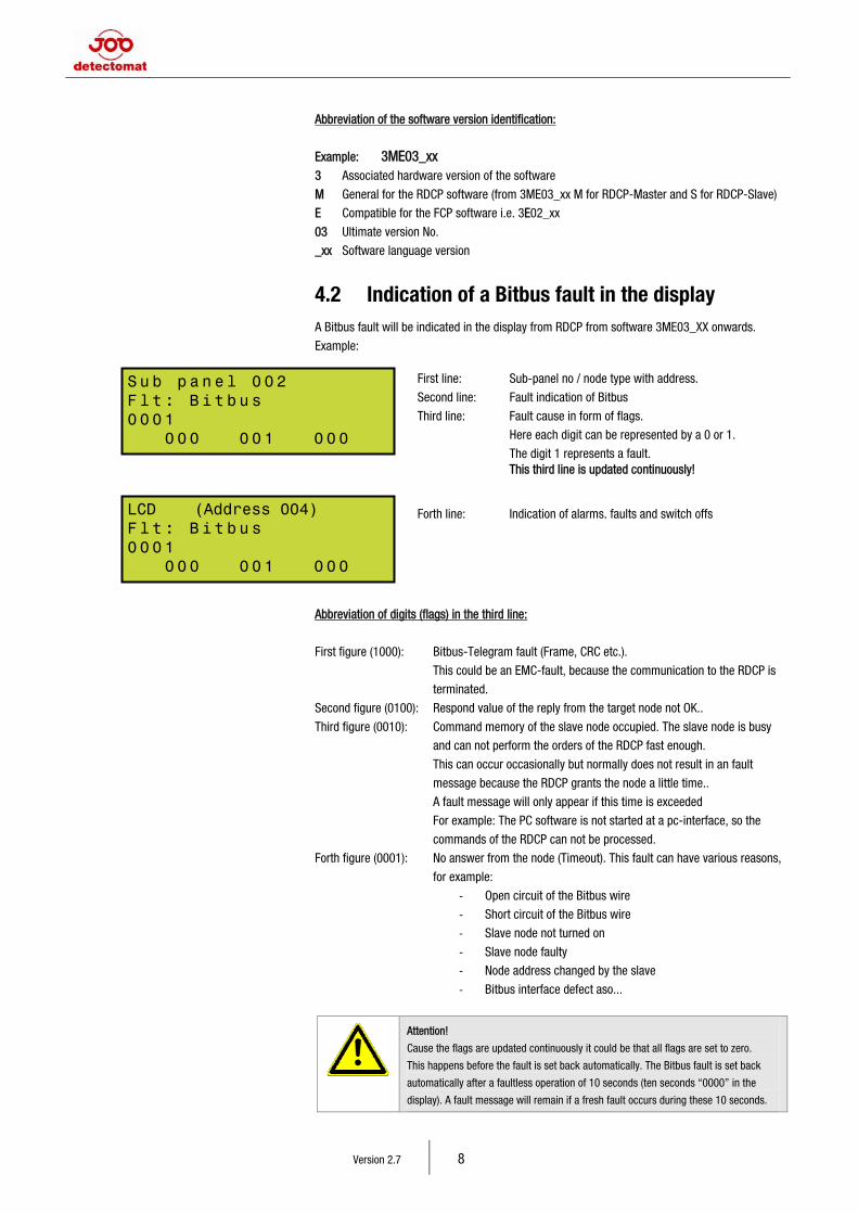
4.2 Indication of a Bitbus fault in the display A Bitbus fault will be indicated in the display from RDCP from software 3ME03_XX onwards.
Example:
Abbreviation of digits (flags) in the third line:
First figure (1000): Bitbus-Telegram fault (Frame, CRC etc.).
This could be an EMC-fault, because the communication to the RDCP is
terminated.
Second figure (0100): Respond value of the reply from the target node not OK..
Third figure (0010): Command memory of the slave node occupied. The slave node is busy
and can not perform the orders of the RDCP fast enough.
This can occur occasionally but normally does not result in an fault
message because the RDCP grants the node a little time..
A fault message will only appear if this time is exceeded
For example: The PC software is not started at a pc-interface, so the
commands of the RDCP can not be processed.
Forth figure (0001): No answer from the node (Timeout). This fault can have various reasons,
for example:
- Open circuit of the Bitbus wire
- Short circuit of the Bitbus wire
- Slave node not turned on
- Slave node faulty
- Node address changed by the slave
- Bitbus interface defect aso...
Attention!
Cause the flags are updated continuously it could be that all flags are set to zero.
This happens before the fault is set back automatically. The Bitbus fault is set back
automatically after a faultless operation of 10 seconds (ten seconds “0000” in the
display). A fault message will remain if a fresh fault occurs during these 10 seconds.
First line: Sub-panel no / node type with address.
Second line: Fault indication of Bitbus
Third line: Fault cause in form of flags.
Here each digit can be represented by a 0 or 1.
The digit 1 represents a fault. This third line is updated continuously! Forth line: Indication of alarms, faults and switch offs
Su b pa n el 0 02 Fl t : B i tb u s 00 0 1 0 00 0 0 1 0 0 0
LCD (Address 004) Fl t : B i tb u s 00 0 1 0 00 0 0 1 0 0 0
15 Remote Display and Control Panel
Version 2.7 9
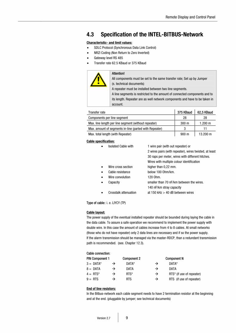
4.3 Specification of the INTEL-BITBUS-Network Characteristic- and limit values: • SDLC Protocol (Synchronous Data Link Control)
• NRZI Coding (Non Return to Zero Inverted)
• Gateway level RS 485
• Transfer rate 62.5 KBaud or 375 KBaud
Attention!
All components must be set to the same transfer rate; Set up by Jumper
(s. technical documents)
A repeater must be installed between two line segments.
A line segments is restricted to the amount of connected components and to
its length. Repeater are as well network components and have to be taken in
account.
Transfer rate 375 KBaud 62,5 KBaud Components per line segment 28 28 Max. line length per line segment (without repeater) 300 m 1.200 m Max. amount of segments in-line (parted with Repeater) 3 11 Max. total length (with Repeater) 900 m 13.200 m
Cable specification:
• Isolated Cable with 1 wire pair (with out repeater) or
2 wires pairs (with repeater), wires twisted, at least
30 raps per meter, wires with different hitches.
Wires with multiple colour identification
• Wire cross section higher than 0,22 mm.
• Cable resistance below 100 Ohm/km.
• Wire convolution 120 Ohm.
• Capacity smaller than 70 nF/km between the wires.
140 nF/km stray capacity
• Crosstalk attenuation at 150 kHz > 40 dB between wires
Type of cable: i. e. LIYCY (TP)
Cable layout: The power supply of the eventual installed repeater should be bounded during laying the cable in
the data cable. To assure a safe operation we recommend to implement the power supply with
double wire. In this case the amount of cables increase from 4 to 8 cables. At small networks
(those who do not have repeater) only 2 data lines are necessary and if so the power supply.
If the alarm transmission should be managed via the master-RDCP, than a redundant transmission
path is recommended. (see. Chapter 12.3).
Cable connection:
PIN Component 1 Component 2 Component N
3 = DATA* DATA* DATA*
8 = DATA DATA DATA
4 = RTS* RTS* RTS* (if use of repeater)
9 = RTS RTS RTS (if use of repeater)
End of line resistors: In the Bitbus-network each cable segment needs to have 2 termination resistor at the beginning
and at the end. (pluggable by jumper; see technical documents)
Version 2.7 10
4.4 Power supply of the RDCP The power supply for the RDCP is 230 VAC. Rechargeable batteries (max. 24 Ah) can be placed
inside the housing for emergency supply. The charging takes place via the main adapter of the
RDCP.
Attention!
To activate the control function of the main adapter the parameter 3 is to be
set to 1 (see Chapter 18.5.2 Parameter).
The RDCP in the 19” assembly version (Art.-No. 30127) needs a separate 24 VDC power supply.
This can be occur via a FCP from the network for example. To assure a safe function we
recommend to carry out the power supply via a double wired cable. The power consumption of the
RDCP is to be regarded with the rechargeable battery.
5 Function description
The RDCP shows all appearing messages of the system and allows to handle al connected Fire-
control-systems. At a corresponding programming it is possible that access authorisation blocks a
FCP or reduces its user level. It is possible to connect multiple RDCP`s in one system. One of them
acts as a Master and the rest as Slaves. The functions of the slaves are just as practicable.
6 Operation-/Service mode
The RDCP operates in two modes, the operation and the service mode. The respective operating
mode is indicated in the LC display in a text format, unless there are special messages.
The operation mode is the normal mode, where the RDCP polls the FCP`s about messages and
events or to control the different FCP`s. For this mode to work, the door of the RDCP must be
closed.
The service mode is activated as soon as the front door is opened (Provided a door contact switch
is present). While opening the door, the transmission line (if the transmission line is connected to
the RDCP) is automatically disabled. Opening the door will also disable the internal buzzer so as
not to irritate staff who may be working near the panel.
7 LCD-Display
Unless there are messages or the unit is in service mode, the top line from the four lines in the
LCD display indicates the current date and time. The third line indicates the mode type
(In Operation or Service).
The back light is activated automatically, i.e. when a key requiring an entry or one of the cursor
keys [ ] / [ ] are pressed the back light is enabled. If no further keys are pressed, the back
light will stay enabled for about 60 seconds before it goes out. If further keys are pressed, the
back light is disabled again 60 seconds after the last key was pressed.
15 Remote Display and Control Panel
Version 2.7 11
7.1 Structure of the LCD-Display: The LCD display automatically shows every incoming message, regardless of whether the
message indicates an alarm, a fault or a disconnection. If a disconnection, fault and alarm
messages are received at the same time, the alarm messages are given priority over the fault
messages, which in turn has priority over the disconnection message, i.e. the message with
higher priority is given precedence over the message with lower priority. The messages are
displayed in the following format (example): 1. Line : Sub panel 001 2. Line : Flt: Z0002 D005 *
3. Line : optional customer text (Can be programmed at the sub panel by the dpt-tool)
4. Line: current message counter The first line shows automatically the sub panel from which the message comes. If a customer
specific text is programmed with the dpt-tool for that panel then this will be indicated instead of
“Sub panel xyz”.
The second line indicates the type of message, the zone, detector number and if type of fault. The symbols identifying the type of message are:
„ Al “ for alarm
„1.AL” for first alarm message in an alarm dependency
„ Flt “ for fault
„ FTA “ for fault technical Alarm (detector zone)
„ Off “ for disabling
„ TA “ for test-alarm
„ PA “ for pre-alarm
„ Info “ for information message
„ Zone “ = conventional zone
„ Z “ = zone (addressable detectors)
„ D “ = detector number within the Zone (for addressable detectors)
The following types of faults are indicated: „ SC “ = short circuit
„ OC “ = open circuit
„ LowV ” = low voltage
„ Ri ” = internal resistance
„ SC ” = short circuit
„ n.FB ” = no feed back If there is no message displayed under “Type of fault”, then the addressable detector has been
removed or is defective. The example above shows an open circuit fault at detector 5 in Zone 2.
How detectors are assigned to zones will be explained in detail below. The first received message
(initial message) will get an “*” as an identification marker at the end of the zone. If several
messages of the same type (e.g. 5 alarms) are received at the same time, the first message is
displayed in the LCD, all following messages can be viewed via the cursor key [ ] and [ ]. Test-alarms are alarms which can be set in the “revision mode” or the “detector test” function.
Pre-alarms only occur in combination with addressable detectors. If the parameter for pre-alarms is set, the FCP will activate a local alarm below the alarm threshold
in the display of the panel and will not transmit the alarm to the fire and rescue services or set off
any sirens.
Version 2.7 12
7.2 Indication of system fault System faults are do not come from detectors or other external devices, but refer to an internal
disturbance from the CPU. The RDCP is equipped with comprehensive monitoring functions which
guarantee that each deviation from the desired state, no matter how small, is indicated as a
message. These messages may have different degrees of priority. They are either indicated in the
LCD display in a text format or only as LED display. Possible system faults and the corresponding
measures to be taken are listed below (ranked according to priority):
Priority Message Meaning Action
1 LED “System” on
continuously, buzzer sounds
continuously
Failure of CPU, FCP
presumably without
function
Notify the manufacturer
and swap the host system
asap!
2 Fault message in LCD:
“Failure detector module xx”
Loop or conventional card
at address indicated lost
communication with the
CPU for at least 20
seconds, possibility of a
total failure!!
Check whether detector
information can be called
up via the diagnosis
function and notify fault
clearing service;
3 Fault message in LCD:
“Failure total check RAM” and
LED “System” on
Memory error at RAM
memory
Take notice to chapter
22.1
4 Fault message in LCD:
”Flt. RTC” LED “system” on.
The system clock has an
invalid time
See chapter 18.2
5 Fault message in LCD:
“Flt. Host” LED “system” on.
The host system has
rebooted
See chapter 22.2
7.3 Current counters in the 4th display line: As soon as messages have been received, the LCD display activates three counters in the bottom,
fourth line of the display. These three-digit counters are directly assigned to the oval buttons
below the LCD display and indicate the current number of messages that have been received up
to that point. Special features: The alarm counter only indicates messages received from different modules. If,
e.g. 2 detectors from Zone 1 and 3 detectors from Zone 2 are in alarm, the alarm counter indicates
002. Browsing with the cursor keys [ ] and [ ] the respective first message of a zone can be
viewed. If, as in the example below, several detectors within the same zone are in alarm, an arrow
pointing to the right will appear in the display next to the first message. By means of the cursor
key [ ] the further detectors may then be displayed.
The buttons under the display are arranged in the sequence 000 000 000 [ Alarm ] [ Fault ] [ Disconnection ]
By pressing one of these buttons, the operator can call up the respective messages onto the
display. If, e.g. the display currently shows an alarm message and the fault counter indicates
“001”, the fault will be indicated in the display after pressing the button “Faults”. If several fault
messages are indicated, the cursor keys [ ] / [ ] can be used to browse through the
messages. The cursor key [ ] always browses in the direction of the most recent message, the
cursor key [ ] in the direction of the older messages. Once the alarm indication function has
been left, the display will automatically jump back to the First alarm message after 30 seconds.
When the cursor key has reached the oldest message, the next keystroke will show the most
recent message (scrolling in a circle) again.
15 Remote Display and Control Panel
Version 2.7 13
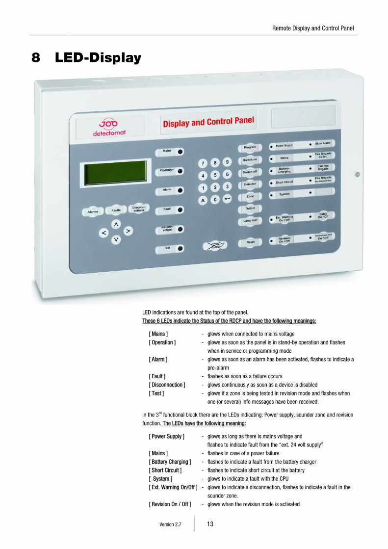
8 LED-Display
LED indications are found at the top of the panel.
These 6 LEDs indicate the Status of the RDCP and have the following meanings: [ Mains ] - glows when connected to mains voltage
[ Operation ] - glows as soon as the panel is in stand-by operation and flashes
when in service or programming mode
[ Alarm ] - glows as soon as an alarm has been activated, flashes to indicate a
pre-alarm
[ Fault ] - flashes as soon as a failure occurs
[ Disconnection ] - glows continuously as soon as a device is disabled
[ Test ] - glows if a zone is being tested in revision mode and flashes when
one (or several) info messages have been received.
In the 3rd functional block there are the LEDs indicating: Power supply, sounder zone and revision
function. The LEDs have the following meaning:
[ Power Supply ] - glows as long as there is mains voltage and
flashes to indicate fault from the “ext. 24 volt supply”
[ Mains ] - flashes in case of a power failure
[ Battery Charging ] - flashes to indicate a fault from the battery charger
[ Short Circuit ] - flashes to indicate short circuit at the battery
[ System ] - glows to indicate a fault with the CPU
[ Ext. Warning On/Off ] - glows to indicate a disconnection, flashes to indicate a fault in the
sounder zone.
[ Revision On / Off ] - glows when the revision mode is activated
Version 2.7 14
The 4th functional block contains the displays for the area “Transmission unit”.
The LEDs have the following meaning:
[ Main Alarm ] - indicates a main alarm, i.e. the panel tries to alert the fire
and rescue services.
[ Fire Brigade called ] - the fire alarm signal was successfully transmitted to the fire
and rescue services.
[ Call Fire Brigade ] - the alarm was not transmitted, the operator has to call
the fire services manually.
[ Fire Brigade - Sabotage alarm transmitted from key deposit box
Key Deposit Box ]
[ Delay On / Off ] - glows if a delayed transmission is activated
[ Transmission Unit - glows if a transmission unit is disabled,
On / Off ] flashes if there is a fault on the control line to the transmission unit
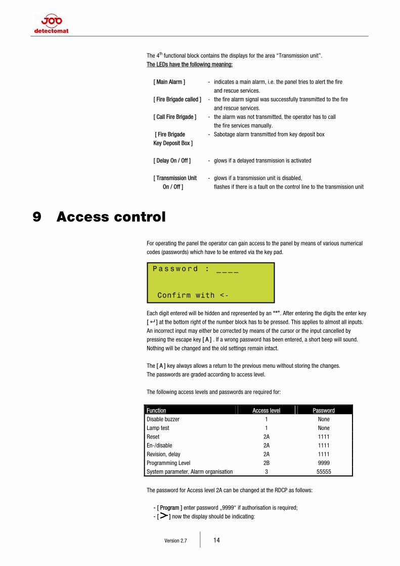
9 Access control
For operating the panel the operator can gain access to the panel by means of various numerical
codes (passwords) which have to be entered via the key pad.
Each digit entered will be hidden and represented by an “*”. After entering the digits the enter key
[ ] at the bottom right of the number block has to be pressed. This applies to almost all inputs.
An incorrect input may either be corrected by means of the cursor or the input cancelled by
pressing the escape key [ A ] . If a wrong password has been entered, a short beep will sound.
Nothing will be changed and the old settings remain intact.
The [ A ] key always allows a return to the previous menu without storing the changes.
The passwords are graded according to access level.
The following access levels and passwords are required for:
Function Access level Password
Disable buzzer 1 None
Lamp test 1 None
Reset 2A 1111
En-/disable 2A 1111
Revision, delay 2A 1111
Programming Level 2B 9999
System parameter, Alarm organisation 3 55555
The password for Access level 2A can be changed at the RDCP as follows:
- [ Program ] enter password „9999“ if authorisation is required;
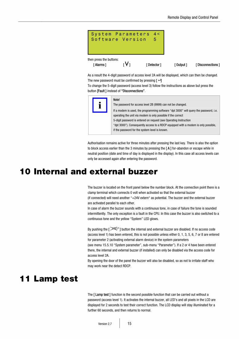
- [ ] now the display should be indicating:
Pa s s wo r d : __ _ _ Confirm with <-
15 Remote Display and Control Panel
Version 2.7 15
then press the buttons:
[ Alarms ] [ ] [ Detector ] [ Output ] [ Disconnections ]
As a result the 4-digit password of access level 2A will be displayed, which can then be changed.
The new password must be confirmed by pressing [ ]
To change the 5-digit password (access level 3) follow the instructions as above but press the
button [Fault ] instead of “Disconnections”.
Note!
The password for access level 2B (9999) can not be changed.
If a modem is used, the programming software “dpt 3000” will query the password, i.e.
operating the unit via modem is only possible if the correct
5-digit password is entered on request (see Operating Instruction
“dpt 3000”). Consequently access to a RDCP equipped with a modem is only possible,
if the password for the system level is known.
Authorisation remains active for three minutes after pressing the last key. There is also the option
to block access earlier than the 3 minutes by pressing the [ A ] for-abandon or escape while in
neutral position (date and time of day is displayed in the display). In this case all access levels can
only be accessed again after entering the password.
10 Internal and external buzzer
The buzzer is located on the front panel below the number block. At the connection point there is a
clamp terminal which connects 0 volt when activated so that the external buzzer
(if connected) will need another “+24V extern“ as potential. The buzzer and the external buzzer
are activated parallel to each other.
In case of alarm the buzzer sounds with a continuous tone, in case of failure the tone is sounded
intermittently. The only exception is a fault in the CPU. In this case the buzzer is also switched to a
continuous tone and the yellow “System” LED glows.
By pushing the [ ] button the internal and external buzzer are disabled. If no access code
(access level 1) has been entered, this is not possible unless either 0, 1, 3, 5, 6, 7 or 8 are entered
for parameter 2 (activating external alarm device) in the system parameters
(see menu 15.5.10 “System parameter”, sub-menu “Parameter”). If a 2 or 4 have been entered
there, the internal and external buzzer (if installed) can only be disabled via the access code for
access level 2A.
By opening the door of the panel the buzzer will also be disabled, so as not to irritate staff who
may work near the detect RDCP.
11 Lamp test
The [ Lamp test ] function is the second possible function that can be carried out without a
password (access level 1). It activates the internal buzzer, all LED’s and all pixels in the LCD are
displayed for 2 seconds to test their correct function. The LCD display will stay illuminated for a
further 60 seconds, and then returns to normal.
Sy s t em Pa r a me t er s 4<So f t wa r e V e rs i on 5
Version 2.7 16
12 Transmission unit in a network
12.1 In general There are three different possibilities of forwarding an alarm status via the transmission unit.
First of all, via the Master-RDCP, secondary via the Master-RDCP’s emergency path, and thirdly by
the sub-panels. Only these three possibilities guaranty a correct alarm transmission.
The settings of these three possibilities are explained here.
The function of a transmission unit in a slave-RDCP is not permitted.
Note!
If the transmission unit is disabled by the key [ Transmission Unit On/Off ] then you can
only enable the transmission unit again by pressing the key on the panel where it has
been turned off. If the transmission unit is disabled from a sub-panel then it is not
possible to enable it again at the Master-RDCP. You need to do this from the sub-panel
where you have disabled it from.
12.2 TU at the Master-RDCP without an emergency path
For this you connect the TU-interface, the main detector and also the FBCP to the Master-RDCP.
This is not permitted at sub-panels and/or further RDCP’s.
The following system parameters need to be set:
Master-RDCP: Parameter 5 = 1
Parameter 9 = 1
Sub-panel: Parameter 5 = 2
Slave-RDCP: Parameter 5 = 2
A complete disabling or enabling of all TU can be done from the master and the slave RDCP.
If the TU of only selected sub-RDCP should be disabled/enabled than the command must be done
at the respective sub-RDCP. A disabling/enabling of selected sub-RDCP is not possible from the
Master RDCP.
The operation of the TU can only be done from the Master-RDCP.
If the TU is disabled from a sub-panel then this panel can not trigger the TU to the Master-RDCP.
All other sub-panels can however still activate the main detector connected to the Master-RDCP. If
the disabling is done at the Master-RDCP then the TU will be disabled throughout the network.
15 Remote Display and Control Panel
Version 2.7 17
12.3 TU at the Master-RDCP with an emergency path If need to connect the TU-interface to the Master-RDCP and the sub-panels:
The connection of FBCP and main detector is only permitted from the Master-RDCP.
The following system parameters need to be set:
Master-RDCP: Parameter 5 = 1
Parameter 9 = 1
Sub-panel: Parameter 5 = 1
Slave-RDCP: Parameter 5 = 2
The TU-interface in the sub-panels needs to operate the emergency-path
(see the connection diagram “TU in network” on Technical-DVD).
The operation of the TU can only be done from the Master-RDCP.
A complete disabling or enabling of all TU can be done from the master and the slave RDCP.
If the TU of only selected sub-RDCP should be disabled/enabled than the command must be done
at the respective sub-RDCP. A disabling/enabling of selected sub-RDCP is not possible from the
Master RDCP.
If the TU is disabled from a sub-panel then this panel will not trigger the TU to the Master-RDCP.
All other sub-panels can however still activate the main detector connected to the Master-RDCP. If
the disabling is done from the Master-RDCP then the TU will be disabled throughout the network.
12.4 TU at the sub-panels For this operation you need to connect the TU-interface, the respective main detector and the
FBCP to each sub-panel.
Attention!
An alarm will only activate the main detector from the panel where the alarm
has been activated from. The main detectors of all the other sub-panels will
not be triggered.
The TU may not be connected to the RDCP’s (Neither Master nor Slave)
The following system parameters need to be set:
Master-RDCP: Parameter 5 = 2
Parameter 9 = 0
Sub-panel: Parameter 5 = 1
Slave-RDCP: Parameter 5 = 2
The TU of the respective sub-panels can be operated from the Master-RDCP. If the TU of all sub-
panels need to be disabled, then this must be done at every sub-panel. If the TU is disabled from
the RDCP or directly from the sub-panel, then the main detectors of the remaining sub-panels can
still be triggered.
Version 2.7 18
13 Delay On/Off
Provided access has been authorised, pushing the [ Delay On/Off ] button will alternately enable or
disable the delayed transmission. The delay is possible regardless where the transmission is
connected to (master or sub control panel). This means that in combination with the day/night
configuration the main alarm is transmitted with a delay, provided the alarm has not been reset in
the meantime. Reaction and investigation times have to be programmed at the sub control panel’s
in the first place, for this function to become effective. The zones which are to be disabled from
sub-panels detect 3004 (plus) must be accordingly programmed in these panels.
An active delay is indicated by means of the corresponding LED glowing and an entry in the LCD
window.
Example procedure to disable the transmission at the sub panel 1:
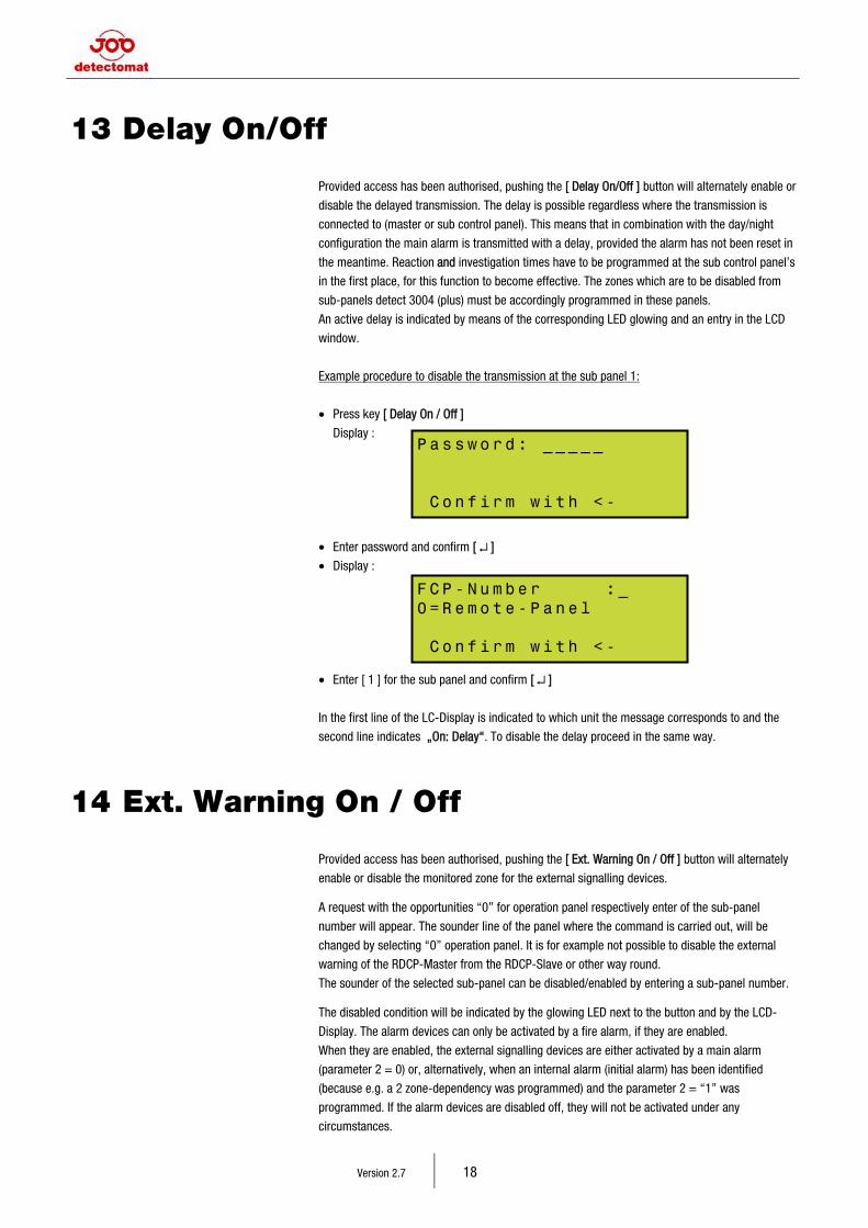
• Press key [ Delay On / Off ]
Display :
• Enter password and confirm [ ↵ ]
• Display :
• Enter [ 1 ] for the sub panel and confirm [ ↵ ]
In the first line of the LC-Display is indicated to which unit the message corresponds to and the
second line indicates „On: Delay“. To disable the delay proceed in the same way.
14 Ext. Warning On / Off
Provided access has been authorised, pushing the [ Ext. Warning On / Off ] button will alternately
enable or disable the monitored zone for the external signalling devices. A request with the opportunities “0” for operation panel respectively enter of the sub-panel
number will appear. The sounder line of the panel where the command is carried out, will be
changed by selecting “0” operation panel. It is for example not possible to disable the external
warning of the RDCP-Master from the RDCP-Slave or other way round.
The sounder of the selected sub-panel can be disabled/enabled by entering a sub-panel number. The disabled condition will be indicated by the glowing LED next to the button and by the LCD-
Display. The alarm devices can only be activated by a fire alarm, if they are enabled.
When they are enabled, the external signalling devices are either activated by a main alarm
(parameter 2 = 0) or, alternatively, when an internal alarm (initial alarm) has been identified
(because e.g. a 2 zone-dependency was programmed) and the parameter 2 = “1” was
programmed. If the alarm devices are disabled off, they will not be activated under any
circumstances.
Pa s s wo r d: _ __ _ _ C o n fi r m w i th <-
F C P - Nu m be r : _ 0= R e mo t e- P a ne l C o n fi r m w i th <-
15 Remote Display and Control Panel
Version 2.7 19
By programming parameter 2 = [ 2 ] or parameter 2 = [ 3 ] it is also possible to deactivate the
external signalling devices by pushing the button [ ]. The difference is that in the first case
the password for access level 2A has to be entered and in the other case the function may be
executed without entering a password. A new incoming alarm will activate the external signalling
devices again.
Procedure to disable the external warning for example from the remote control panel 1.
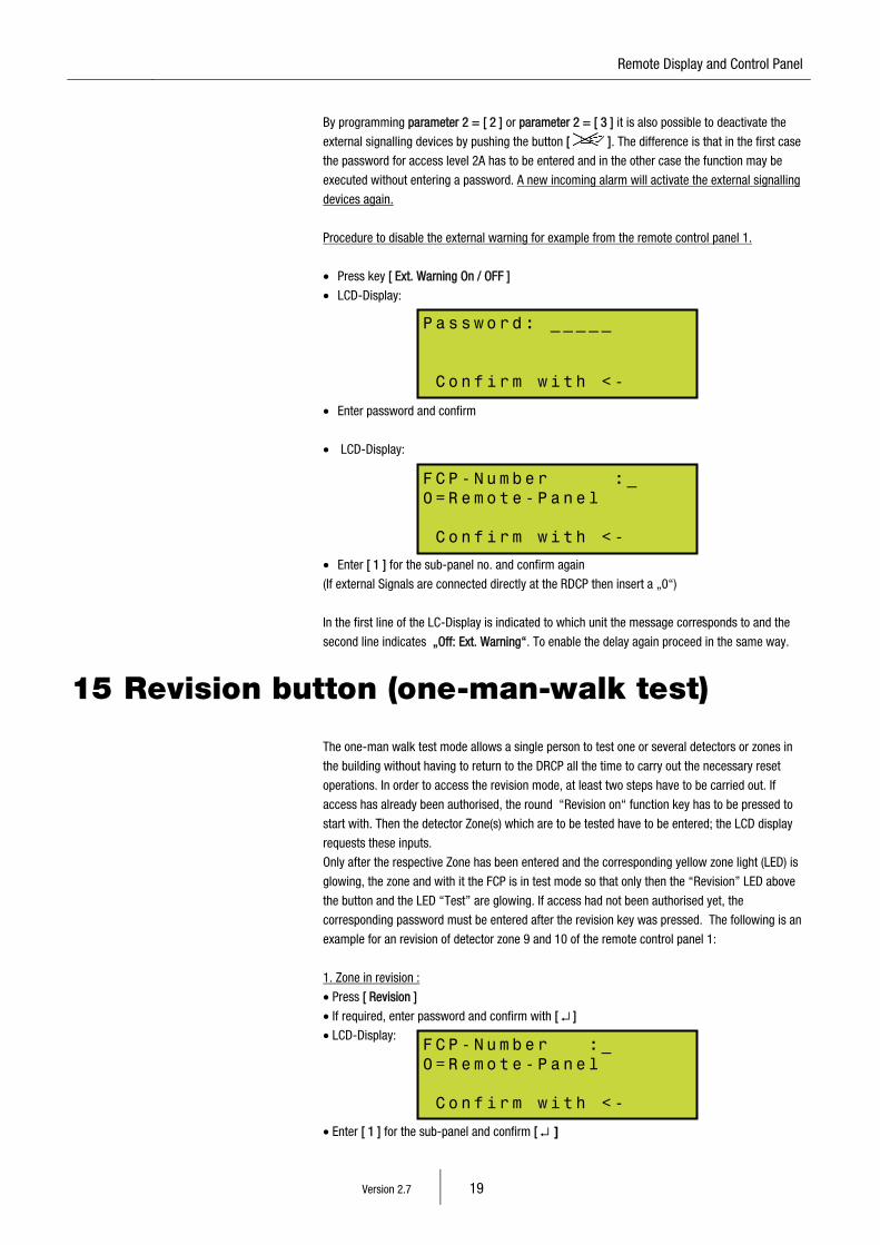
• Press key [ Ext. Warning On / OFF ]
• LCD-Display:
• Enter password and confirm
• LCD-Display:
• Enter [ 1 ] for the sub-panel no. and confirm again
(If external Signals are connected directly at the RDCP then insert a „0“)
In the first line of the LC-Display is indicated to which unit the message corresponds to and the
second line indicates „Off: Ext. Warning“. To enable the delay again proceed in the same way.
15 Revision button (one-man-walk test)
The one-man walk test mode allows a single person to test one or several detectors or zones in
the building without having to return to the DRCP all the time to carry out the necessary reset
operations. In order to access the revision mode, at least two steps have to be carried out. If
access has already been authorised, the round “Revision on“ function key has to be pressed to
start with. Then the detector Zone(s) which are to be tested have to be entered; the LCD display
requests these inputs.
Only after the respective Zone has been entered and the corresponding yellow zone light (LED) is
glowing, the zone and with it the FCP is in test mode so that only then the “Revision” LED above
the button and the LED “Test” are glowing. If access had not been authorised yet, the
corresponding password must be entered after the revision key was pressed. The following is an
example for an revision of detector zone 9 and 10 of the remote control panel 1:
1. Zone in revision :
• Press [ Revision ]
• If required, enter password and confirm with [ ↵ ]
• LCD-Display:
• Enter [ 1 ] for the sub-panel and confirm [ ↵ ]
Pa s s wo r d: _ __ _ _ C o n fi r m w i th <-
F C P - Nu m be r : _ 0= R e mo t e- P a ne l C o n fi r m w i th <-
FC P - Nu m be r : _ 0= R e mo t e- P a ne l C o n fi r m w i th <-
Version 2.7 20
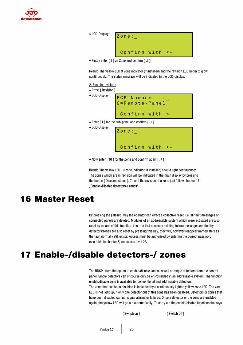
• LCD-Display:
• Firstly enter [ 9 ] as Zone and confirm [ ↵ ]
Result: The yellow LED 9 Zone indicator (if installed) and the revision LED begin to glow
continuously. The status message will be indicated in the LCD-display. 2. Zone in revision :
• Press [ Revision ]
• LCD-Display :
• Enter [ 1 ] for the sub-panel and confirm [ ↵ ]
• LCD-Display :
• Now enter [ 10 ] for the Zone and confirm again [ ↵ ] .
Result: The yellow LED 10 zone indicator (if installed) should light continuously.
The zones which are in revision will be indicated in the main display by pressing
the button [ Disconnections ]. To end the revision of a zone just follow chapter 17
„Enable-/Disable detectors-/ zones“
16 Master Reset
By pressing the [ Reset ] key the operator can effect a collective reset, i.e. all fault messages of
connected panels are deleted. Modules of an addressable system which were activated are also
reset by means of this function. It is true that currently existing failure messages emitted by
detectors/zones are also reset by pressing this key, they will, however reappear immediately as
the fault normally still exists. Access must be authorised by entering the correct password
(see table in chapter 8) on access level 2A.
17 Enable-/disable detectors-/ zones
The RDCP offers the option to enable/disable zones as well as single detectors from the control
panel. Single detectors can of course only be en-/disabled in an addressable system. The function
enable/disable zone is available for conventional and addressable detectors.
The zone that has been disabled is indicated by a continuously lighted yellow zone LED. The zone
LED is not light up, if only one detector out of this zone has been disabled. Detectors or zones that
have been disabled can not signal alarms or failures. Once a detector or the zone are enabled
again, the yellow LED will go out automatically. To carry out the enable/disable functions the keys
[ Switch on ] [ Switch off ]
FC P - Nu m be r : _ 0= R e mo t e- P a ne l C o n fi r m w i th <-
Zo n e :_ C o n fi r m w i th <-
Zo n e :_ C o n fi r m w i th <-

15 Remote Display and Control Panel
Version 2.7 21
are available. After the function key has been pressed, the information which sub control panel
and which detector or zone you want to disable has to be entered. Carrying out the operation is
supported by the LC display which shows which input the RDCP is expecting at any given moment.
Attention!
From Software 5A_20_xx (FCP detect 3016) or 3A_40_xx (FCP detect 3004)
it is possible to control an extinguish card. The control lines on this extinguish
card are equal to be handled as conventional lines.
17.1 Enabling/disabling addressable detectors Example for disabling detectors 5-10 in zone 1 of sub -control panel:
• Press [ Switch off ]
• Enter password if required and confirm with [ ↵ ]
• LCD-Display :
• Enter [ 1 ] for sub-panel and confirm [ ↵ ]
• LCD Display :
• Press [ Detector ]
• LCD-Display :
• First of all enter [ 1 ] for the zone and confirm [ ↵ ]
• Enter first detector, in this example [ 5 ] and confirm
• And the last detector, in this example [ 10 ] and confirm.
The disabled detectors are indicated in the display and can be scrolled by pressing the cursor keys
[ ] / [ ]
17.2 En-/Disabling conventional zones-/ lines Example for disabling conventional zone 5 in sub-panel 1:
• Press [ Switch off ]
• Enter password if required and confirm with [ ↵ ]
• LCD-Display:
FC P - Nu m be r : _ 0= R e mo t e- P a ne l C o n fi r m w i th <-
De t e ct o r o f f ? Zo n e o f f ? Ou t p ut of f ? ( A) b or t
Zo n e : _ fr o m D e te c . : to D e te c . :
FC P - Nu m be r : _ 0= R e mo t e- P a ne l C o n fi r m w i th <-
Version 2.7 22
• Enter [ 1 ] for sub-panel and confirm [ ↵ ]
• LCD Display:
• Press [ Zone ]
• LCD-Display:
• Enter [ 5 ] and confirm [ ↵ ]
The disabled zones are indicated in the display and can be scrolled by pressing the cursor keys
[ ] / [ ].
For extinguish lines proceed equal to the example above.
17.3 Enabling/disabling outputs The function key [ Output ] on the front of the RDCP is available for disabling the electronic outputs
(failure transmission zone, accumulated fault relays and electronic output “fault “) and for
disabling the open collector alarm outputs. Disabling of these outputs is possible after the number
code [ 1111 ] or corresponding code has been entered. The disabling process is indicated in the
LC display in text format.
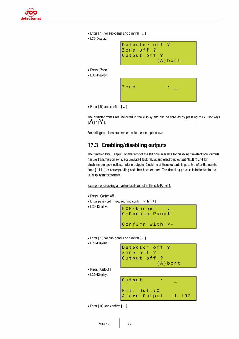
Example of disabling a master-fault-output in the sub-Panel 1:
• Press [ Switch off ]
• Enter password if required and confirm with [ ↵ ]
• LCD-Display:
• Enter [ 1 ] for sub-panel and confirm [ ↵ ]
• LCD-Display:
• Press [ Output ]
• LCD-Display:
• Enter [ 0 ] and confirm [ ↵ ]
De t e ct o r o f f ? Zo n e o f f ? Ou t p ut of f ? ( A) b or t
Zo n e : _
FC P - Nu m be r : _ 0= R e mo t e- P a ne l Co n f ir m w i t h < -
De t e ct o r o f f ? Zo n e o f f ? Ou t p ut of f ? ( A) b or t
Ou t p ut : _ Fl t . O u t. : 0 Al a r m- O ut p u t :1 - 1 92
15 Remote Display and Control Panel
Version 2.7 23
By selecting the numbers of an alarm output (1 - 128) it is possible to deactivate certain alarm
outputs. These would then not be activated if there was an alarm in the corresponding zone.
If the centralised alarm and single alarms are to be enabled again, the procedure is the same,
the process only has to be started by pressing the [ Switch on ] key.
Because a RDCP has no alarm output it is logically only possible to disable the fault output.
Therefore by selecting “0” for remote panel only this output can be entered.
To select the outputs of the sub-panels enter the number of the sub-panel and then select the
desired output which is to be enabled/disabled.
18 Programming of the RDCP
The operator can access the first programme level of the RDCP by pressing the [ Programme ] key
and subsequently adding the correct access code. Only authorised staff should be allowed to
programme the RDCP as this is the area in which comprehensive manipulations of the alarm
organisation can be carried out. Incorrect input data may influence the alarm raising function of
the RDCP negatively. Therefore the item “alarm organisation” can be accessed in the sub-menu
“system parameter”, which is protected by a further 5-digit password. On the programme level
diagnosis and print functions may be carried out and the date and time set. The alarm counter,
which cannot be reset, can be displayed and certain system parameters, which are also
additionally secured, may be configured. System parameters are software switches to
activate/deactivate various functions or configurations. If the wrong menu has been selected by
mistake, it is always possible to return to the previous menu by pressing the [ A ] key, (A for
Abort). Even if some data has already been entered, entering the data has not been completed yet,
however, pressing the [ A ] button will stop everything and nothing has been changed.
The RDCP only accepts the inputs after they have been completed and confirmed.
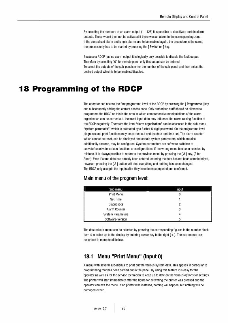
Main menu of the program level:
Sub menu Input
Print Menu 0
Set Time 1
Diagnostics 2
Alarm Counter 3
System Parameters 4
Software-Version 5
The desired sub-menu can be selected by pressing the corresponding figures in the number block.
Item 4 is called up to the display by entering cursor key to the right [ > ]. The sub-menus are
described in more detail below.
18.1 Menu "Print Menu" (Input 0) A menu with several sub-menus to print out the various system data. This applies in particular to
programming that has been carried out in the panel. By using this feature it is easy for the
operator as well as for the service technician to keep up to date on the various options for settings.
The printer will start immediately after the figure for activating the printer was pressed and the
operator can exit the menu. If no printer was installed, nothing will happen, but nothing will be
damaged either.
Version 2.7 24
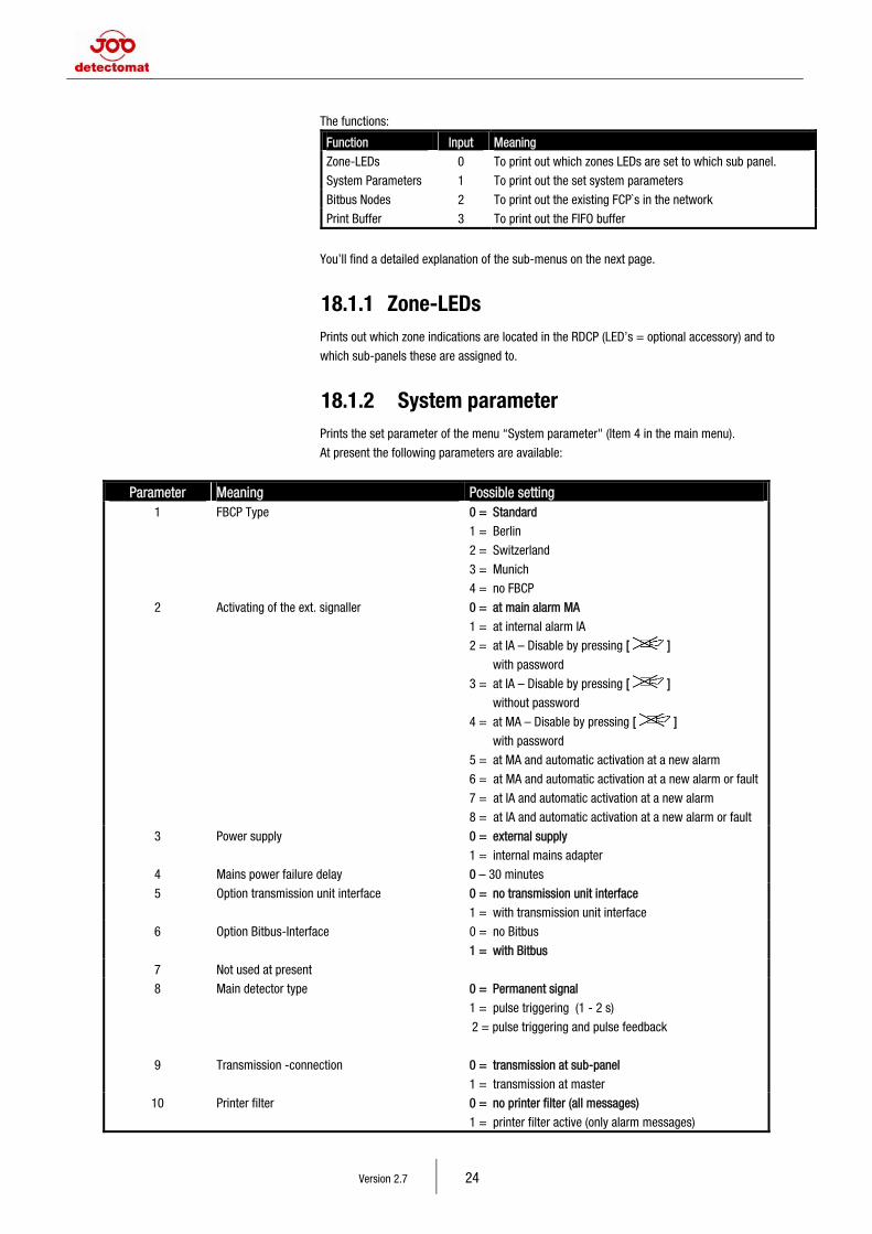
The functions:
Function Input Meaning
Zone-LEDs 0 To print out which zones LEDs are set to which sub panel.
System Parameters 1 To print out the set system parameters
Bitbus Nodes 2 To print out the existing FCP`s in the network
Print Buffer 3 To print out the FIFO buffer
You’ll find a detailed explanation of the sub-menus on the next page.
18.1.1 Zone-LEDs Prints out which zone indications are located in the RDCP (LED’s = optional accessory) and to
which sub-panels these are assigned to.
18.1.2 System parameter Prints the set parameter of the menu “System parameter" (Item 4 in the main menu).
At present the following parameters are available:
Parameter Meaning Possible setting 1 FBCP Type 0 = Standard
1 = Berlin
2 = Switzerland
3 = Munich
4 = no FBCP
2 Activating of the ext. signaller 0 = at main alarm MA
1 = at internal alarm IA
2 = at IA – Disable by pressing [ ]
with password
3 = at IA – Disable by pressing [ ]
without password
4 = at MA – Disable by pressing [ ]
with password
5 = at MA and automatic activation at a new alarm
6 = at MA and automatic activation at a new alarm or fault
7 = at IA and automatic activation at a new alarm
8 = at IA and automatic activation at a new alarm or fault
3 Power supply 0 = external supply
1 = internal mains adapter
4 Mains power failure delay 0 – 30 minutes
5 Option transmission unit interface 0 = no transmission unit interface
1 = with transmission unit interface
6 Option Bitbus-Interface 0 = no Bitbus
1 = with Bitbus
7 Not used at present
8 Main detector type 0 = Permanent signal
1 = pulse triggering (1 - 2 s)
2 = pulse triggering and pulse feedback
9 Transmission -connection 0 = transmission at sub-panel
1 = transmission at master
10 Printer filter 0 = no printer filter (all messages)
1 = printer filter active (only alarm messages)
15 Remote Display and Control Panel
Version 2.7 25
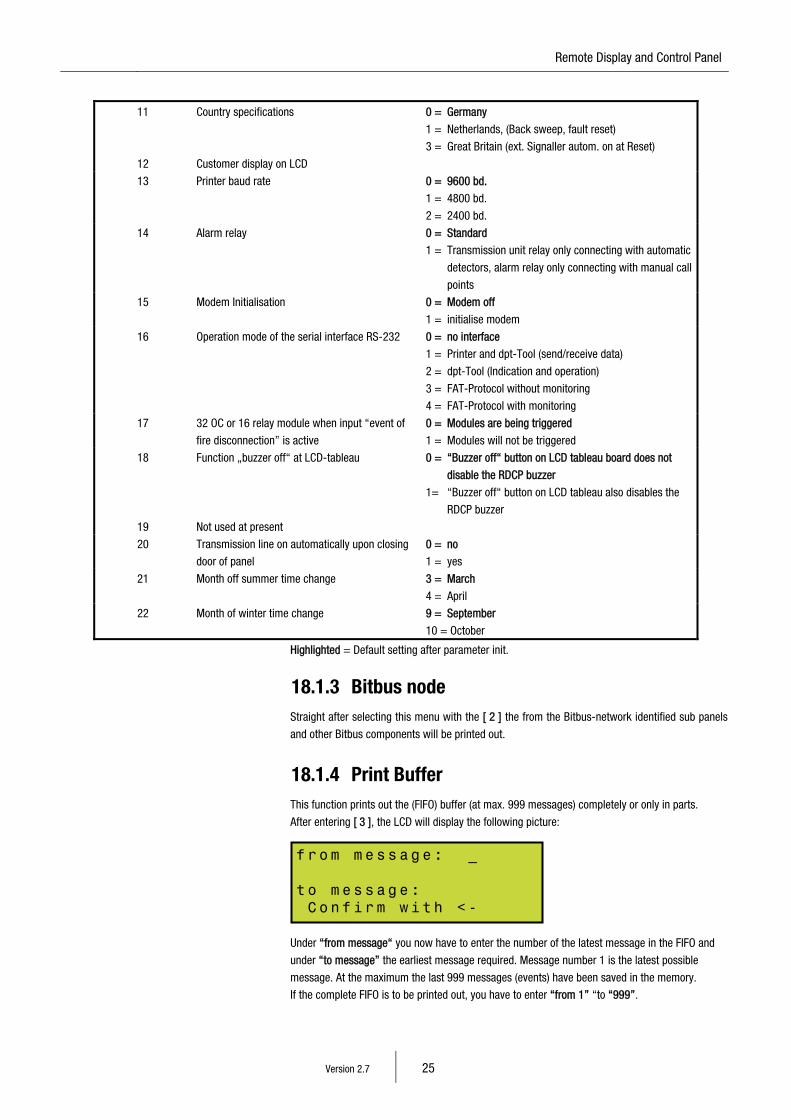
11 Country specifications 0 = Germany
1 = Netherlands, (Back sweep, fault reset)
3 = Great Britain (ext. Signaller autom. on at Reset)
12 Customer display on LCD
13 Printer baud rate 0 = 9600 bd.
1 = 4800 bd.
2 = 2400 bd.
14 Alarm relay 0 = Standard
1 = Transmission unit relay only connecting with automatic
detectors, alarm relay only connecting with manual call
points
15 Modem Initialisation 0 = Modem off
1 = initialise modem
16 Operation mode of the serial interface RS-232 0 = no interface
1 = Printer and dpt-Tool (send/receive data)
2 = dpt-Tool (Indication and operation)
3 = FAT-Protocol without monitoring
4 = FAT-Protocol with monitoring
17 32 OC or 16 relay module when input “event of
fire disconnection” is active
0 = Modules are being triggered
1 = Modules will not be triggered
18 Function „buzzer off“ at LCD-tableau 0 = “Buzzer off“ button on LCD tableau board does not
disable the RDCP buzzer
1= “Buzzer off“ button on LCD tableau also disables the
RDCP buzzer
19 Not used at present
20 Transmission line on automatically upon closing
door of panel
0 = no
1 = yes
21 Month off summer time change 3 = March
4 = April
22 Month of winter time change 9 = September
10 = October
Highlighted = Default setting after parameter init.
18.1.3 Bitbus node Straight after selecting this menu with the [ 2 ] the from the Bitbus-network identified sub panels
and other Bitbus components will be printed out.
18.1.4 Print Buffer This function prints out the (FIFO) buffer (at max. 999 messages) completely or only in parts.
After entering [ 3 ], the LCD will display the following picture:
Under “from message“ you now have to enter the number of the latest message in the FIFO and
under “to message” the earliest message required. Message number 1 is the latest possible
message. At the maximum the last 999 messages (events) have been saved in the memory.
If the complete FIFO is to be printed out, you have to enter “from 1” “to “999”.
fr o m m e ss a g e: _ to m es s ag e : C o n fi r m w i th <-
Version 2.7 26
18.2 Menu "Set Time" (Input 1)
Note!
The RTC-Data (Real Time Clock) of the RDCP is validated.
If incorrect, this data is found in the memory then the RTC-Fault message will appear.
The system-LED and fault-LED will be activated. To reset the fault message enter the
menu LEVEL “System parameter”, press [ A ] to go back to the previous level and
check the date and time [ 1 ] “Set Time”.
The setting of the time in a network can only be changed in the master.
The current time and date are inserted in the first zone of the display and the LCD cursor is below
the first figure at the far left. The second zone has the day of the week inserted and the third zone
the current setting regarding summer/winter time. By moving the cursor keys left/right the cursor
may now be moved within the zone. Once you have reached the position where a change is to be
entered, this is done directly by entering the correct figure on the number pad (number block).
By pressing the cursor keys up/down [ ] / [ ] the day of the week can be changed.
This menu also allows the operator to change manually from summer to winter time (and vice
versa). This is only necessary, if the setting is not correct on Start-up. If the time is to be set
manually, you must use the cursor key [ ] to scroll down to “Sunday”. If you then press the
cursor key [ ] once again, the setting changes from summer to winter time or the other way
round, depending on which time was originally set. Please make sure that you set the correct day
again by means of the [ ] cursor key. After the correct data have been entered, the input is
confirmed by pressing the Enter [ ↵ ] key and saved.
Once summer or winter time have been set correctly, no further adjustments will be necessary,
provided parameters 21 and 22 are set correctly (see menu “System parameter“).
After setting up the right time and date, these must be confirmed and saved with the [ ↵ ] key.
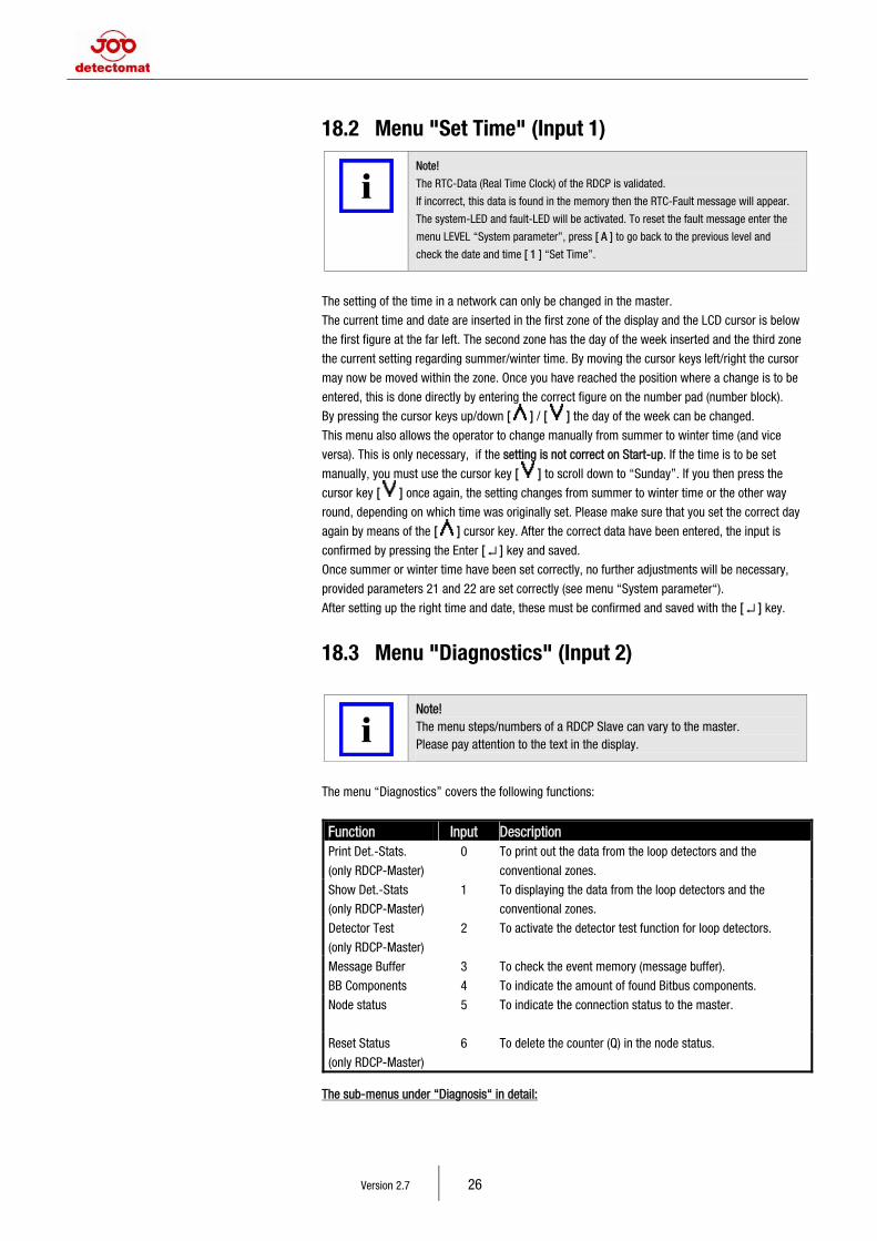
18.3 Menu "Diagnostics" (Input 2)
Note! The menu steps/numbers of a RDCP Slave can vary to the master. Please pay attention to the text in the display.
The menu “Diagnostics” covers the following functions:
Function Input Description Print Det.-Stats.
(only RDCP-Master)
0 To print out the data from the loop detectors and the
conventional zones.
Show Det.-Stats
(only RDCP-Master)
1 To displaying the data from the loop detectors and the
conventional zones.
Detector Test
(only RDCP-Master)
2 To activate the detector test function for loop detectors.
Message Buffer 3 To check the event memory (message buffer).
BB Components 4 To indicate the amount of found Bitbus components.
Node status
5 To indicate the connection status to the master.
Reset Status
(only RDCP-Master)
6 To delete the counter (Q) in the node status.
The sub-menus under “Diagnosis“ in detail:
15 Remote Display and Control Panel
Version 2.7 27
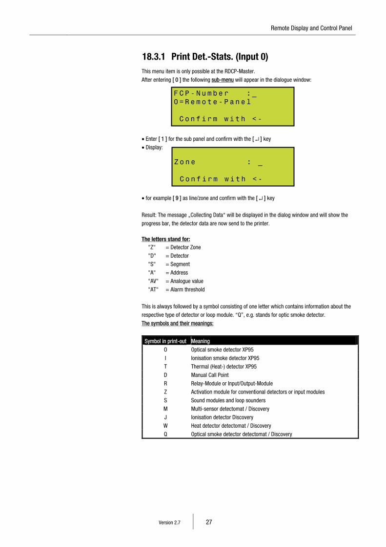
18.3.1 Print Det.-Stats. (Input 0) This menu item is only possible at the RDCP-Master.
After entering [ 0 ] the following sub-menu will appear in the dialogue window:
• Enter [ 1 ] for the sub panel and confirm with the [ ↵ ] key
• Display:
• for example [ 9 ] as line/zone and confirm with the [ ↵ ] key
Result: The message „Collecting Data“ will be displayed in the dialog window and will show the
progress bar, the detector data are now send to the printer.
The letters stand for: "Z" = Detector Zone
"D" = Detector
"S" = Segment
"A" = Address
"AV" = Analogue value
"AT" = Alarm threshold
This is always followed by a symbol consisting of one letter which contains information about the
respective type of detector or loop module. “Q”, e.g. stands for optic smoke detector.
The symbols and their meanings:
Symbol in print-out Meaning
O Optical smoke detector XP95
I Ionisation smoke detector XP95
T Thermal (Heat-) detector XP95
D Manual Call Point
R Relay-Module or Input/Output-Module
Z Activation module for conventional detectors or input modules
S Sound modules and loop sounders
M Multi-sensor detectomat / Discovery
J Ionisation detector Discovery
W Heat detector detectomat / Discovery
Q Optical smoke detector detectomat / Discovery
FC P - Nu m be r : _ 0= R e mo t e- P a ne l C o n fi r m w i th <-
Zo n e : _ C o n fi r m w i th <-
Version 2.7 28
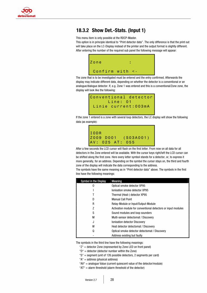
18.3.2 Show Det.-Stats. (Input 1) This menu item is only possible at the RDCP-Master. This option is in principle identical to “Print detector data”. The only difference is that the print out will take place on the LC-Display instead of the printer and the output format is slightly different. After entering the number of the required sub panel the following message will appear:
The zone that is to be investigated must be entered and the entry confirmed. Afterwards the display may indicate different data, depending on whether the detector is a conventional or an analogue/dialogue detector. If, e.g. Zone 1 was entered and this is a conventional/Zone zone, the display will look like the following:
If the zone 1 entered is a zone with several loop detectors, the LC display will show the following
data (as example):
After a few seconds the LCD cursor will flash on the first letter. From now on all data for all detectors in the Zone entered will be available. With the cursor keys right/left the LCD cursor can be shifted along the first zone. Here every letter symbol stands for a detector, or, to express it more generally, for an address. Depending on the symbol the cursor stays on, the third and fourth zone of the display will indicate the data corresponding to the address. The symbols have the same meaning as in “Print detector data” above. The symbols in the first line have the following meanings:
Symbol in the Display Meaning
O Optical smoke detector XP95
I Ionisation smoke detector XP95
T Thermal (Heat-) detector XP95
D Manual Call Point
R Relay-Module or Input/Output-Module
Z Activation module for conventional detectors or input modules
S Sound modules and loop sounders
M Multi-sensor detectomat / Discovery
J Ionisation detector Discovery
W Heat detector detectomat / Discovery
Q Optical smoke detector detectomat / Discovery
- Address existing but faulty The symbols in the third line have the following meanings: “Z“ = detector Zone (represented by Zone LED on front panel) “D“ = detector (detector number within the Zone) “S“ = segment (unit of 126 possible detectors, 2 segments per card) “A“ = address (physical address) “AV“ = analogue Value (current quiescent value of the detector/module) “AT“ = alarm threshold (alarm threshold of the detector)
Co n v en t io n a l d et e c to r L in e : 0 1 L i n ie cu r r en t :0 0 3 mA
IO D R Z0 0 9 D 0 01 (S 0 3A 0 0 1) AV : 02 5 A T : 0 5 5
Zo n e : C o n fi r m w i th <-
15 Remote Display and Control Panel
Version 2.7 29
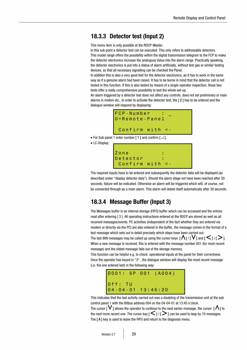
18.3.3 Detector test (Input 2) This menu item is only possible at the RDCP-Master. In this sub point a detector test can be executed. This only refers to addressable detectors. This model range offers the possibility within the digital transmission telegram to the FCP to make the detector electronics increase the analogous Value into the alarm range. Practically speaking, the detector electronics is put into a status of alarm artificially, without test gas or similar testing devices, so that all necessary signalling can be checked the Panel. In addition this is also a very good test for the detector electronics, as it has to work in the same way as if a genuine alarm had been raised. It has to be borne in mind that the detector cell is not tested in this function. If this is also tested by means of a single-operator inspection, these two tests offer a really comprehensive possibility to test the whole set-up. An alarm triggered by a detector test does not affect any controls, does not set preliminary or main alarms in motion etc,. In order to activate the detector test, the [ 2 ] has to be entered and the dialogue window will respond by displaying:
• For Sub panel 1 enter number [ 1 ] and confirm [ ↵ ].
• LC-Display:
The required inputs have to be entered and subsequently the detector data will be displayed (as
described under “display detector data”). Should the alarm stage not have been reached after 30
seconds, failure will be indicated. Otherwise an alarm will be triggered which will, of course, not
be connected through as a main alarm. This alarm will delete itself automatically after 30 seconds.
18.3.4 Message Buffer (Input 3) The Messages buffer is an internal storage (FIFO) buffer which can be accessed and the entries
read after entering [ 3 ]. All operating instructions entered at the RDCP are stored as well as all
received messages/events. PC activities (independent of the fact whether they are entered via
modem or directly via the PC) are also entered in the buffer, the message comes in the format of a
text message which sets out in detail precisely which steps have been carried out.
The last 999 messages may be called up using the cursor keys [ ] / [ ] and [ < ] / [ > ].
When a new message is received, this is entered with the message number 001 (for most recent
message) and the oldest message falls out of the storage memory.
This function can be helpful e.g. to check operational inputs at the panel for their correctness.
Once the operator has keyed in “3“ , the dialogue window will display the most recent message
(i.e. the one entered last) in the following way:
This indicates that the last activity carried out was a disabling of the transmission unit at the sub
control panel 1 with the Bitbus address 004 on the 04-04-01 at 13:45 o’clock.
The cursor [ ] allows the operator to continue to the next earlier message, the cursor [ ] to
the next more recent one. The cursor key [ < ] / [ > ] can be used to leap by 10 messages.
The [ A ] key is used to leave the FIFO and return to the diagnosis menu.
FC P - Nu m be r : _ 0= R e mo t e- P a ne l C o n fi r m w i th <-
Zo n e : De t e ct o r : C o n fi r m w i th <-
D0 0 1 : S P 0 0 1 ( A0 0 4 ) Of f : T U 04 - 0 4- 0 1 1 3 :4 5 :2 0
Version 2.7 30
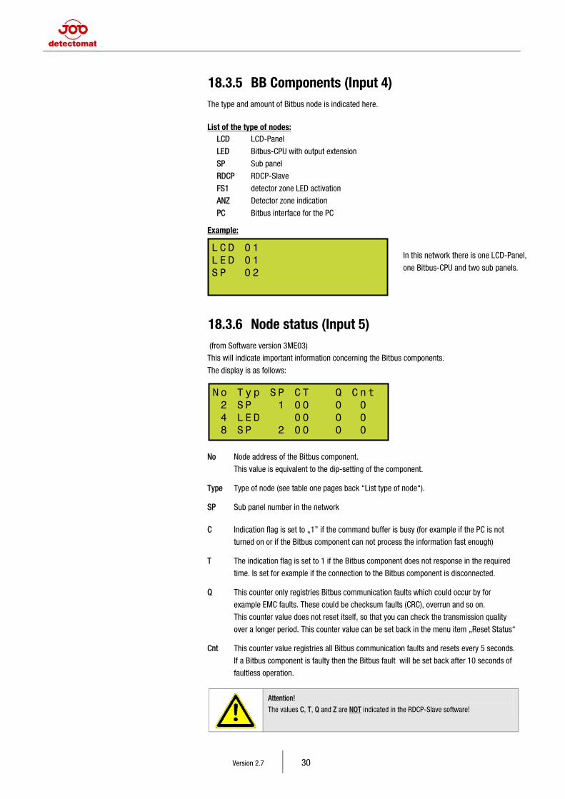
18.3.5 BB Components (Input 4) The type and amount of Bitbus node is indicated here.
List of the type of nodes: LCD LCD-Panel
LED Bitbus-CPU with output extension
SP Sub panel
RDCP RDCP-Slave
FS1 detector zone LED activation
ANZ Detector zone indication
PC Bitbus interface for the PC Example:
18.3.6 Node status (Input 5) (from Software version 3ME03)
This will indicate important information concerning the Bitbus components.
The display is as follows:
No Node address of the Bitbus component.
This value is equivalent to the dip-setting of the component. Type Type of node (see table one pages back “List type of node“). SP Sub panel number in the network C Indication flag is set to „1” if the command buffer is busy (for example if the PC is not
turned on or if the Bitbus component can not process the information fast enough) T The indication flag is set to 1 if the Bitbus component does not response in the required
time. Is set for example if the connection to the Bitbus component is disconnected. Q This counter only registries Bitbus communication faults which could occur by for
example EMC faults. These could be checksum faults (CRC), overrun and so on.
This counter value does not reset itself, so that you can check the transmission quality
over a longer period. This counter value can be set back in the menu item „Reset Status“ Cnt This counter value registries all Bitbus communication faults and resets every 5 seconds.
If a Bitbus component is faulty then the Bitbus fault will be set back after 10 seconds of
faultless operation.
Attention!
The values C, T, Q and Z are NOT indicated in the RDCP-Slave software!
In this network there is one LCD-Panel,
one Bitbus-CPU and two sub panels.
LC D 01 LE D 01 SP 02
No T yp SP C T Q C nt 2 S P 1 0 0 0 0 4 L ED 0 0 0 0 8 S P 2 0 0 0 0
15 Remote Display and Control Panel
Version 2.7 31
18.3.7 Reset-Status (Input 6) This menu item is only possible at the RDCP-Master.
The Q counter in the node status will be reset for all Bitbus components
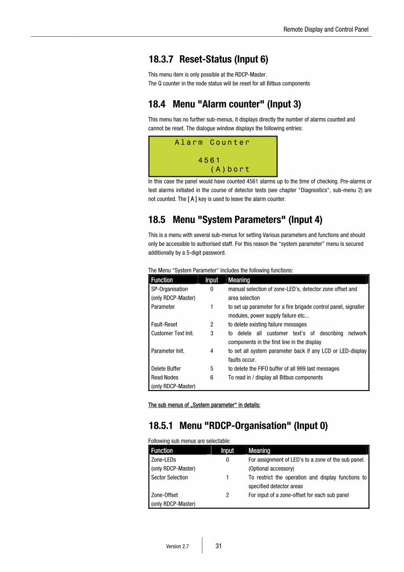
18.4 Menu "Alarm counter" (Input 3) This menu has no further sub-menus, it displays directly the number of alarms counted and
cannot be reset. The dialogue window displays the following entries:
In this case the panel would have counted 4561 alarms up to the time of checking. Pre-alarms or
test alarms initiated in the course of detector tests (see chapter “Diagnostics“, sub-menu 2) are
not counted. The [ A ] key is used to leave the alarm counter.
18.5 Menu "System Parameters" (Input 4) This is a menu with several sub-menus for setting Various parameters and functions and should
only be accessible to authorised staff. For this reason the “system parameter” menu is secured
additionally by a 5-digit password.
The Menu “System Parameter“ includes the following functions:
Function Input Meaning SP-Organisation
(only RDCP-Master)
0 manual selection of zone-LED’s, detector zone offset and
area selection
Parameter 1 to set up parameter for a fire brigade control panel, signaller
modules, power supply failure etc...
Fault-Reset 2 to delete existing failure messages
Customer Text Init. 3 to delete all customer text’s of describing network
components in the first line in the display
Parameter Init. 4 to set all system parameter back if any LCD or LED-display
faults occur.
Delete Buffer 5 to delete the FIFO buffer of all 999 last messages
Read Nodes
(only RDCP-Master)
6 To read in / display all Bitbus components
The sub menus of „System parameter“ in details:
18.5.1 Menu "RDCP-Organisation" (Input 0) Following sub menus are selectable:
Function Input Meaning Zone-LEDs
(only RDCP-Master)
0 For assignment of LED’s to a zone of the sub panel.
(Optional accessory)
Sector Selection 1 To restrict the operation and display functions to
specified detector areas
Zone-Offset
(only RDCP-Master)
2 For input of a zone-offset for each sub panel
Al a rm C ou n te r 4 5 6 1 ( A) b or t
Version 2.7 32
The RDCP “alarm organisation” sub-menus in detail:
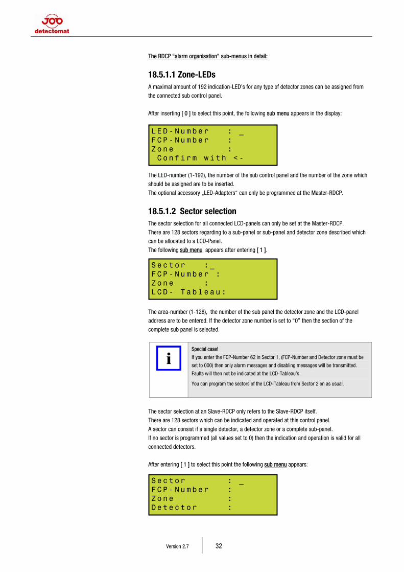
18.5.1.1 Zone-LEDs A maximal amount of 192 indication-LED’s for any type of detector zones can be assigned from
the connected sub control panel.
After inserting [ 0 ] to select this point, the following sub menu appears in the display:
The LED-number (1-192), the number of the sub control panel and the number of the zone which
should be assigned are to be inserted.
The optional accessory „LED-Adapters“ can only be programmed at the Master-RDCP.
18.5.1.2 Sector selection The sector selection for all connected LCD-panels can only be set at the Master-RDCP.
There are 128 sectors regarding to a sub-panel or sub-panel and detector zone described which
can be allocated to a LCD-Panel.
The following sub menu appears after entering [ 1 ].
The area-number (1-128), the number of the sub panel the detector zone and the LCD-panel
address are to be entered. If the detector zone number is set to “0” then the section of the
complete sub panel is selected.
Special case!
If you enter the FCP-Number 62 in Sector 1, (FCP-Number and Detector zone must be
set to 000) then only alarm messages and disabling messages will be transmitted.
Faults will then not be indicated at the LCD-Tableau’s .
You can program the sectors of the LCD-Tableau from Sector 2 on as usual.
The sector selection at an Slave-RDCP only refers to the Slave-RDCP itself.
There are 128 sectors which can be indicated and operated at this control panel.
A sector can consist if a single detector, a detector zone or a complete sub-panel.
If no sector is programmed (all values set to 0) then the indication and operation is valid for all
connected detectors.
After entering [ 1 ] to select this point the following sub menu appears:
LE D - Nu m be r : _ FC P - Nu m be r : Zo n e : C o n fi r m w i th <-
Se c t or : _ FC P - Nu m be r : Zo n e : LC D - T a bl e a u:
Se c t or : _ FC P - Nu m be r : Zo n e : De t e ct o r :

15 Remote Display and Control Panel
Version 2.7 33
The sector-number (1-128), the number of the sub panel the zone and the detector number are to
be entered.
If zone and detector number are set to 0 then the involved area is set to the whole sub panel.
If the zone is set to 0 then the whole zone is included to the area of the specified sub panel.
18.5.1.3 Detector zone Offset A programming of an Offset is only at the RDCP-Master possible.
A RDCP-Slave can only indicate programmed Offsets.
Each sub control panel in a network can be given an offset to receive a continuously running
detector numbering. After entering [ 2 ] to select this menu a dialog window with following
sub menu appears:
The sub panel number and the offset for this sub panel are to be entered here. If for example a
zone-offset of 100 is programmed for the sub panel 2 than a message of the first zone from this
panel will be indicated as zone 101. The zone-offset can only be programmed at the master RDCP.
After programming all offsets it is obligatory to read in the nodes of the Bitbus configuration or
cut the power supply for a few seconds at the Master RDCP. Only now the programmed offsets are
send to all network components and sub control panel’s who have a LC-display.
Please pay attention to the following information:
All programming within a subpanel, for example detector zone settings, the alarm dependency’s
and the programming of active modules always refer to the normal detector zone of a single FCP,
even if there is a detector zone offset within a network.
- A detect 3010/3016 FCP can handle max. 192 zones,
- A detect 3004 can handle max. 128 zones.
A detector zone offset for a sub panel will be added to the factual existing detector zones.
The Zone numbers of all display- and printer outputs, event buffer, disablements and revisions will
be calculated by the detector zone offset.
If there are no detector zone offsets within a network then you will always be requested to enter
the sub panel number to operate disablements and revisions at the RDCP’s.
If there is a detector zone offset within a network, then you only need to enter the zone number.
Every zone number within a network is unique.
The detector zone offset must increase with rising SP-No. This means that if a detector zone offset
of 200 is programmed to SP 2 then you can not programme a zone offset of 100 to SP 3.
The zone offset of SP 3 must then be higher than 200.
If you use a detector zone offset within a network, then a detector zone offset needs to be
programmed to all sub-panels. It is not allowed to have a SP in-between with an detector zone
offset of 0000.
Only exception:
SP1 can be programmed with an offset of 0000 and all not existing sub panels are always to be
programmed to a detector zone offset 0000.
FC P - Nu m be r : _ Zo n e -O f fs e t : C o n fi r m w i th <-
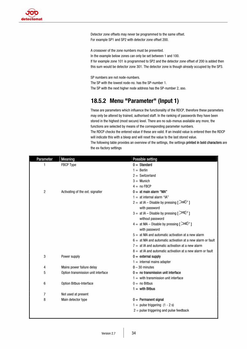
Version 2.7 34
Detector zone offsets may never be programmed to the same offset.
For example SP1 and SP2 with detector zone offset 200.
A crossover of the zone numbers must be prevented.
In the example below zones can only be set between 1 and 100.
If for example zone 101 is programmed to SP2 and the detector zone offset of 200 is added then
this sum would be detector zone 301. The detector zone is though already occupied by the SP3.
SP numbers are not node-numbers.
The SP with the lowest node-no. has the SP-number 1.
The SP with the next higher node address has the SP-number 2, aso.
18.5.2 Menu "Parameter" (Input 1) These are parameters which influence the functionality of the RDCP, therefore these parameters
may only be altered by trained, authorised staff. In the ranking of passwords they have been
stored in the highest (most secure) level. There are no sub-menus available any more, the
functions are selected by means of the corresponding parameter numbers.
The RDCP checks the entered value if these are valid. If an invalid value is entered then the RDCP
will indicate this with a bleep and will reset the value to the last stored value.
The following table provides an overview of the settings, the settings printed in bold characters are
the ex-factory settings
Parameter Meaning Possible setting 1 FBCP Type 0 = Standard
1 = Berlin
2 = Switzerland
3 = Munich
4 = no FBCP
2 Activating of the ext. signaller 0 = at main alarm “MA”
1 = at internal alarm “IA”
2 = at IA – Disable by pressing [ ]
with password
3 = at IA – Disable by pressing [ ]
without password
4 = at MA – Disable by pressing [ ]
with password
5 = at MA and automatic activation at a new alarm
6 = at MA and automatic activation at a new alarm or fault
7 = at IA and automatic activation at a new alarm
8 = at IA and automatic activation at a new alarm or fault
3 Power supply 0 = external supply
1 = internal mains adapter
4 Mains power failure delay 0 – 30 minutes
5 Option transmission unit interface 0 = no transmission unit interface
1 = with transmission unit interface
6 Option Bitbus-Interface 0 = no Bitbus
1 = with Bitbus
7 Not used at present
8 Main detector type 0 = Permanent signal
1 = pulse triggering (1 - 2 s)
2 = pulse triggering and pulse feedback
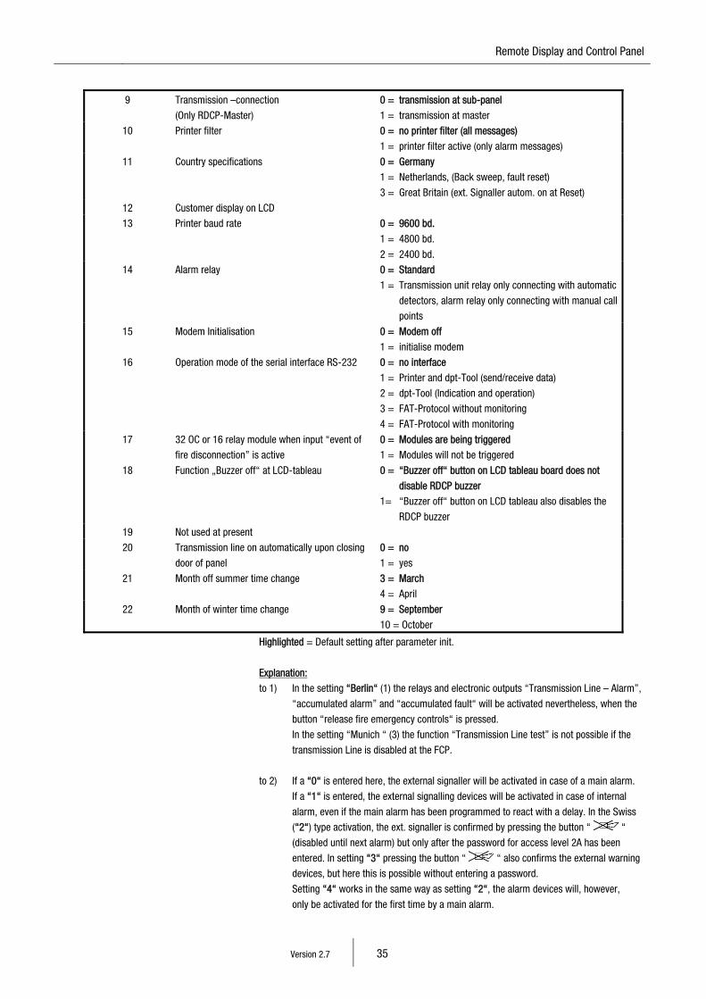
15 Remote Display and Control Panel
Version 2.7 35
9 Transmission –connection
(Only RDCP-Master)
0 = transmission at sub-panel
1 = transmission at master
10 Printer filter 0 = no printer filter (all messages)
1 = printer filter active (only alarm messages)
11 Country specifications 0 = Germany
1 = Netherlands, (Back sweep, fault reset)
3 = Great Britain (ext. Signaller autom. on at Reset)
12 Customer display on LCD
13 Printer baud rate 0 = 9600 bd.
1 = 4800 bd.
2 = 2400 bd.
14 Alarm relay 0 = Standard
1 = Transmission unit relay only connecting with automatic
detectors, alarm relay only connecting with manual call
points
15 Modem Initialisation 0 = Modem off
1 = initialise modem
16 Operation mode of the serial interface RS-232 0 = no interface
1 = Printer and dpt-Tool (send/receive data)
2 = dpt-Tool (Indication and operation)
3 = FAT-Protocol without monitoring
4 = FAT-Protocol with monitoring
17 32 OC or 16 relay module when input “event of
fire disconnection” is active
0 = Modules are being triggered
1 = Modules will not be triggered
18 Function „Buzzer off“ at LCD-tableau 0 = “Buzzer off“ button on LCD tableau board does not
disable RDCP buzzer
1= “Buzzer off“ button on LCD tableau also disables the
RDCP buzzer
19 Not used at present
20 Transmission line on automatically upon closing
door of panel
0 = no
1 = yes
21 Month off summer time change 3 = March
4 = April
22 Month of winter time change 9 = September
10 = October
Highlighted = Default setting after parameter init.
Explanation:
to 1) In the setting “Berlin“ (1) the relays and electronic outputs “Transmission Line – Alarm”,
“accumulated alarm” and “accumulated fault“ will be activated nevertheless, when the
button “release fire emergency controls“ is pressed.
In the setting “Munich “ (3) the function “Transmission Line test” is not possible if the
transmission Line is disabled at the FCP.
to 2) If a “0“ is entered here, the external signaller will be activated in case of a main alarm.
If a “1“ is entered, the external signalling devices will be activated in case of internal
alarm, even if the main alarm has been programmed to react with a delay. In the Swiss
(“2“) type activation, the ext. signaller is confirmed by pressing the button “ “
(disabled until next alarm) but only after the password for access level 2A has been
entered. In setting “3“ pressing the button “ “ also confirms the external warning
devices, but here this is possible without entering a password.
Setting “4“ works in the same way as setting “2“, the alarm devices will, however,
only be activated for the first time by a main alarm.
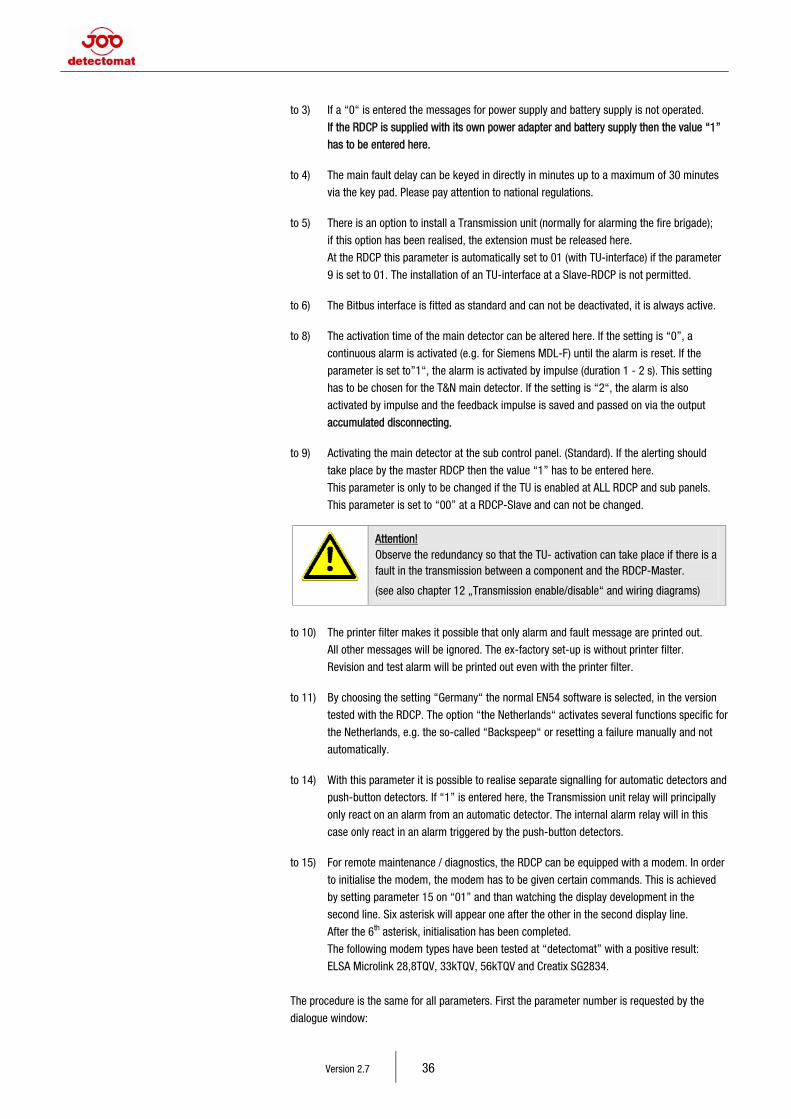
Version 2.7 36
to 3) If a “0“ is entered the messages for power supply and battery supply is not operated.
If the RDCP is supplied with its own power adapter and battery supply then the value “1”
has to be entered here. to 4) The main fault delay can be keyed in directly in minutes up to a maximum of 30 minutes
via the key pad. Please pay attention to national regulations. to 5) There is an option to install a Transmission unit (normally for alarming the fire brigade);
if this option has been realised, the extension must be released here.
At the RDCP this parameter is automatically set to 01 (with TU-interface) if the parameter
9 is set to 01. The installation of an TU-interface at a Slave-RDCP is not permitted. to 6) The Bitbus interface is fitted as standard and can not be deactivated, it is always active. to 8) The activation time of the main detector can be altered here. If the setting is “0”, a
continuous alarm is activated (e.g. for Siemens MDL-F) until the alarm is reset. If the
parameter is set to”1“, the alarm is activated by impulse (duration 1 - 2 s). This setting
has to be chosen for the T&N main detector. If the setting is “2“, the alarm is also
activated by impulse and the feedback impulse is saved and passed on via the output
accumulated disconnecting. to 9) Activating the main detector at the sub control panel. (Standard). If the alerting should
take place by the master RDCP then the value “1” has to be entered here.
This parameter is only to be changed if the TU is enabled at ALL RDCP and sub panels.
This parameter is set to “00” at a RDCP-Slave and can not be changed.
Attention! Observe the redundancy so that the TU- activation can take place if there is a fault in the transmission between a component and the RDCP-Master.
(see also chapter 12 „Transmission enable/disable“ and wiring diagrams)
to 10) The printer filter makes it possible that only alarm and fault message are printed out.
All other messages will be ignored. The ex-factory set-up is without printer filter.
Revision and test alarm will be printed out even with the printer filter. to 11) By choosing the setting “Germany“ the normal EN54 software is selected, in the version
tested with the RDCP. The option “the Netherlands“ activates several functions specific for
the Netherlands, e.g. the so-called “Backspeep“ or resetting a failure manually and not
automatically. to 14) With this parameter it is possible to realise separate signalling for automatic detectors and
push-button detectors. If “1” is entered here, the Transmission unit relay will principally
only react on an alarm from an automatic detector. The internal alarm relay will in this
case only react in an alarm triggered by the push-button detectors. to 15) For remote maintenance / diagnostics, the RDCP can be equipped with a modem. In order
to initialise the modem, the modem has to be given certain commands. This is achieved
by setting parameter 15 on “01” and than watching the display development in the
second line. Six asterisk will appear one after the other in the second display line.
After the 6th asterisk, initialisation has been completed.
The following modem types have been tested at “detectomat” with a positive result:
ELSA Microlink 28,8TQV, 33kTQV, 56kTQV and Creatix SG2834.
The procedure is the same for all parameters. First the parameter number is requested by the
dialogue window:
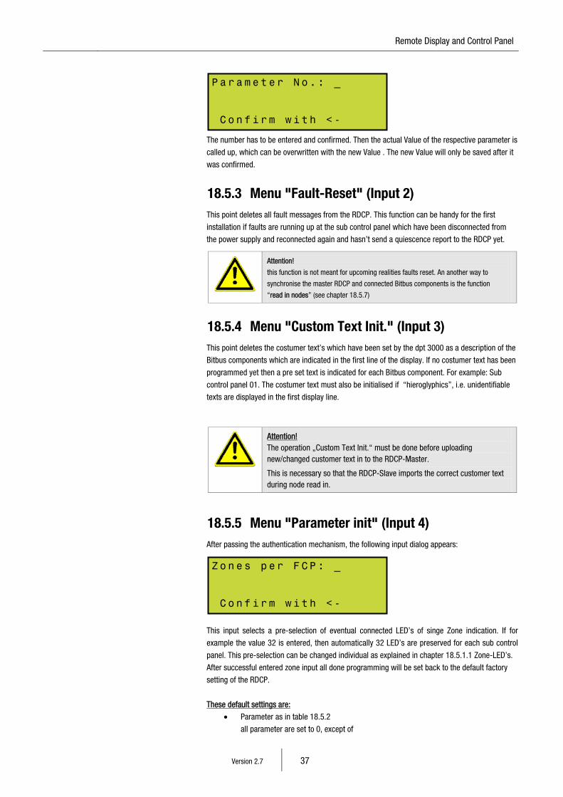
15 Remote Display and Control Panel
Version 2.7 37
The number has to be entered and confirmed. Then the actual Value of the respective parameter is
called up, which can be overwritten with the new Value . The new Value will only be saved after it
was confirmed.
18.5.3 Menu "Fault-Reset" (Input 2) This point deletes all fault messages from the RDCP. This function can be handy for the first
installation if faults are running up at the sub control panel which have been disconnected from
the power supply and reconnected again and hasn’t send a quiescence report to the RDCP yet.
Attention!
this function is not meant for upcoming realities faults reset. An another way to
synchronise the master RDCP and connected Bitbus components is the function
“read in nodes” (see chapter 18.5.7)
18.5.4 Menu "Custom Text Init." (Input 3) This point deletes the costumer text’s which have been set by the dpt 3000 as a description of the
Bitbus components which are indicated in the first line of the display. If no costumer text has been
programmed yet then a pre set text is indicated for each Bitbus component. For example: Sub
control panel 01. The costumer text must also be initialised if “hieroglyphics”, i.e. unidentifiable
texts are displayed in the first display line.
Attention! The operation „Custom Text Init.“ must be done before uploading new/changed customer text in to the RDCP-Master.
This is necessary so that the RDCP-Slave imports the correct customer text during node read in.
18.5.5 Menu "Parameter init" (Input 4) After passing the authentication mechanism, the following input dialog appears:
This input selects a pre-selection of eventual connected LED’s of singe Zone indication. If for
example the value 32 is entered, then automatically 32 LED’s are preserved for each sub control
panel. This pre-selection can be changed individual as explained in chapter 18.5.1.1 Zone-LED’s.
After successful entered zone input all done programming will be set back to the default factory
setting of the RDCP.
These default settings are:
• Parameter as in table 18.5.2
all parameter are set to 0, except of
Pa r a me t er N o. : _ C o n fi r m w i th <-
Zo n e s p er F CP : _ C o n fi r m w i th <-
Version 2.7 38
• Parameter 6 = 1
• Parameter 21 = 3
• Parameter 22 = 10
• all sectors of the Area selection are set to 0
• all detector zone-offsets are set to 0
These parameters are stored permanently in the battery-backed RAM store of the CPU.
If, however, these parameters should be lost through some disruption (flash of lightning,
short-circuit), the operator has the possibility to re-load the parameters (re-establish ex-factory
settings) using the “parameters init”. Lost parameters can e.g. be the reason for faulty LED or
faulty messages in the LC Display.
Once this function has been started, the software of the CPU loads the ex-factory settings without
further interference from outside. It has to be borne in mind, however, that all parameters are back
to their ex-factory settings. This means that all changes to the programming have been deleted,
not, however the specific customer texts for the detectors. In any case all LED and LCD displays
will function correctly again.
After entering [ 4 ] to select this input, the command has to be confirmed by pressing the Enter
key. This is a safety precaution in order to avoid inadvertent deletion.
18.5.6 Menu "Delete Buffer" (Input 5) This point deletes all hidden and shown messages. The authorisation code must be entered to
protect the FIFO of being deleted by accident.
18.5.7 Menu "Read Nodes" (Input 6) The Master-RDCP starts a Bitbus configuration. Therefore all connected components are read out
and displayed. Programmed costumer texts are send to all components which have a LC-Display.
Programmed detector zone offsets are send to the sub panels (FCP`s). Active messages are read
and indicated at every component.
18.6 Menu "Software-Version" (Input 5) There are no further sub-menus under this menu, it directly displays the software version currently
used by the central processor. The second line will indicate the type of RDCP (Master or Slave)
If the panel displays a fault: “Flt: Checksum Ram” then the fault location will be indicated in the
second line of the display. See chapter 22.1 “Details on the fault ”Checksum RAM”.
Furthermore the set baud rate and the node address will be indicated in the display.
15 Remote Display and Control Panel
Version 2.7 39
19 Accessories
19.1 RDCP-LED-Interface (Art. 30128) incl. Bitbus-CPU and flat cable adapter
The RDCP-LED-Interface in planed to retrofit a single detector zone indication to the 19”version
stepped RDCP. Up to 192 Zones are possible. If more than one RDCP is installed and every RDCP
supplied with a single zone indication than all indicate a fault or alarm in case.
The module consists of a universal Bitbus-CPU (MBC277) and a adapter-circuit board which can
be connected by a 26-pin flat cable to the single indicators. The flat cable between the adapter
circuit board and the LED board is included in delivery.
Both circuit board are mounted in a plastic tray which can be snapped onto DIN-bar.
For the LED-circuit boards the single zone-indication are in use. Please watch for the Jumper
configuration on the backside of the circuit board.
For installation in 19“ RDCP you need additional a 19“-front panel (Order: 30167) for respectively
2 zone indications.
The RDCP-LED-Interface receives per DIP–Switch an own Bitbus-Address which must be bigger
than 1 and smaller as 64. The RDCP-LED-Interface receives per DIP–Switch an own Bitbus-
Address which must be bigger than 1 and smaller as 64.
With help of the “dpt 3000” software it is possible to programme up to 192 zones.
This component will be recognised as type „FS1” during reading in nodes (Chapter 18.5.7)
19.2 Bitbus CPU (Order no. 30119) For activation of “Extension for Bitbus CPU” (Order no. 30120/30122).
Attention!
Programming is done with the Bitbus Programming Modem (Order no 30139).
The „Extension for Bitbus CPU“ is developed to program electronic outputs respectively relays.
6 functions can be set for every output which can be programmed by an “AND” or “OR” link.
The following functions can be set:
• Accumulative Alarm
• Accumulative fault
• Accumulative disablement
• Alarm detector/zone
• Fault detector/zone
• Disable detector/zone
• Fault/disable transmission
• Fault/disable external signalling devices
• KDB Alarm
• KDB Open
• Main alarm
• Call fire brigade
• Fire brigade alarmed
• Fault power supply
• Internal buzzer
This component is indicated as „LED” during “Read in nodes”.
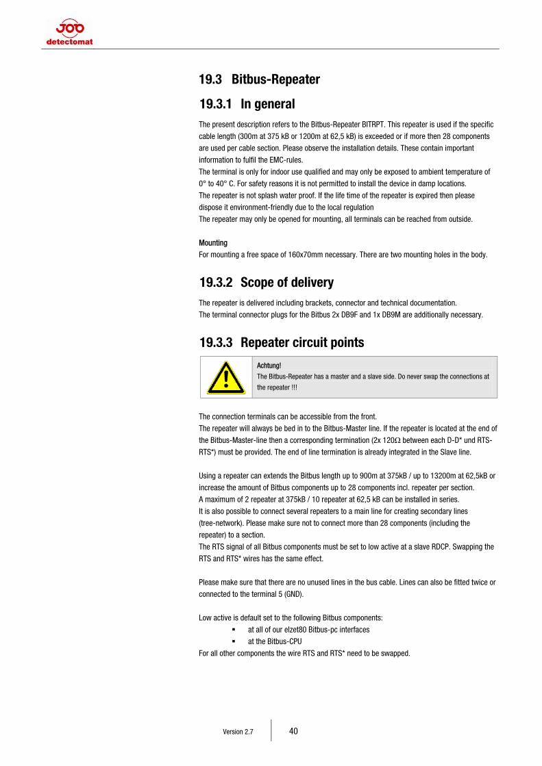
Version 2.7 40
19.3 Bitbus-Repeater
19.3.1 In general The present description refers to the Bitbus-Repeater BITRPT. This repeater is used if the specific
cable length (300m at 375 kB or 1200m at 62,5 kB) is exceeded or if more then 28 components
are used per cable section. Please observe the installation details. These contain important
information to fulfil the EMC-rules.
The terminal is only for indoor use qualified and may only be exposed to ambient temperature of
0° to 40° C. For safety reasons it is not permitted to install the device in damp locations.
The repeater is not splash water proof. If the life time of the repeater is expired then please
dispose it environment-friendly due to the local regulation
The repeater may only be opened for mounting, all terminals can be reached from outside.
Mounting
For mounting a free space of 160x70mm necessary. There are two mounting holes in the body.
19.3.2 Scope of delivery The repeater is delivered including brackets, connector and technical documentation.
The terminal connector plugs for the Bitbus 2x DB9F and 1x DB9M are additionally necessary.
19.3.3 Repeater circuit points
Achtung!
The Bitbus-Repeater has a master and a slave side. Do never swap the connections at
the repeater !!!
The connection terminals can be accessible from the front.
The repeater will always be bed in to the Bitbus-Master line. If the repeater is located at the end of
the Bitbus-Master-line then a corresponding termination (2x 120Ω between each D-D* und RTS-
RTS*) must be provided. The end of line termination is already integrated in the Slave line.
Using a repeater can extends the Bitbus length up to 900m at 375kB / up to 13200m at 62,5kB or
increase the amount of Bitbus components up to 28 components incl. repeater per section.
A maximum of 2 repeater at 375kB / 10 repeater at 62,5 kB can be installed in series.
It is also possible to connect several repeaters to a main line for creating secondary lines
(tree-network). Please make sure not to connect more than 28 components (including the
repeater) to a section.
The RTS signal of all Bitbus components must be set to low active at a slave RDCP. Swapping the
RTS and RTS* wires has the same effect.
Please make sure that there are no unused lines in the bus cable. Lines can also be fitted twice or
connected to the terminal 5 (GND).
Low active is default set to the following Bitbus components:
at all of our elzet80 Bitbus-pc interfaces
at the Bitbus-CPU
For all other components the wire RTS and RTS* need to be swapped.
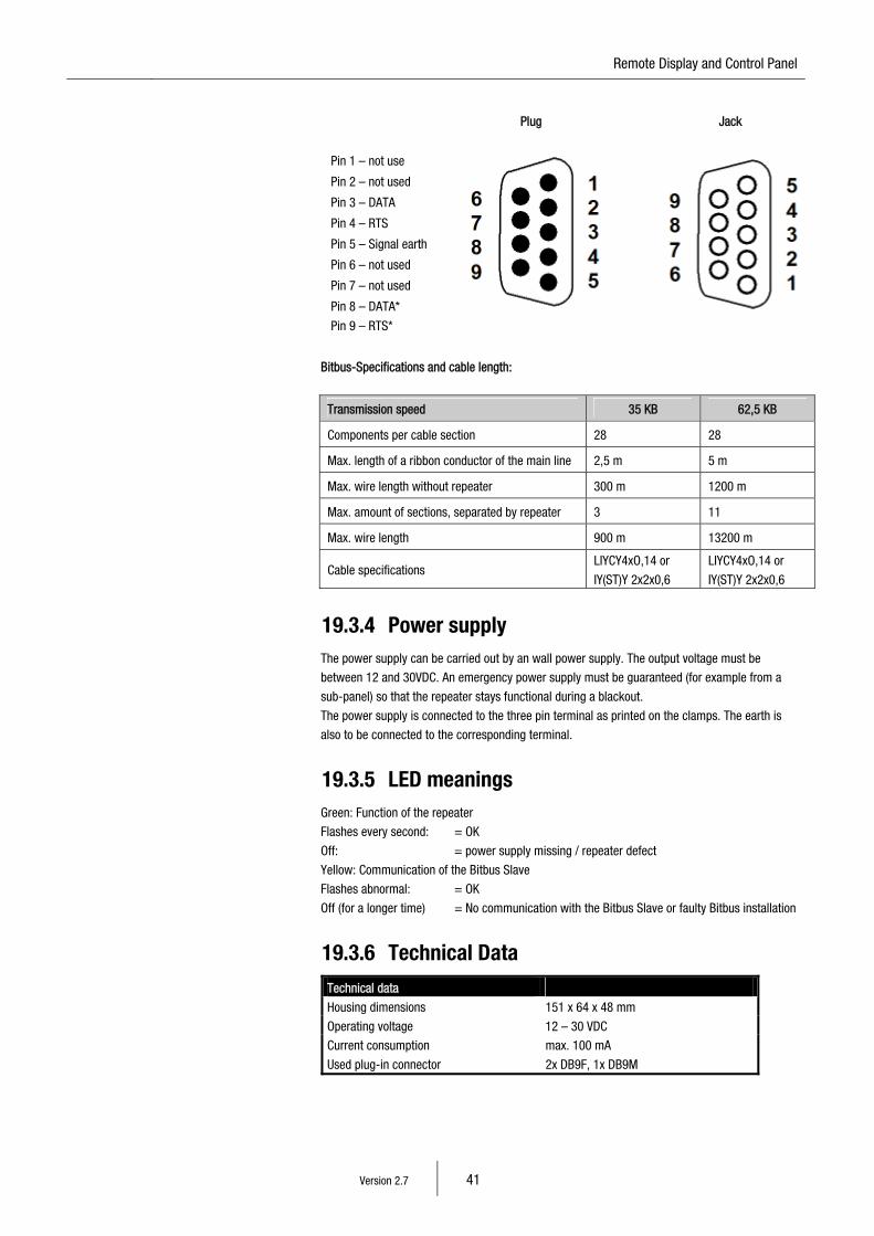
15 Remote Display and Control Panel
Version 2.7 41
Plug Jack
Pin 1 – not use
Pin 2 – not used
Pin 3 – DATA
Pin 4 – RTS
Pin 5 – Signal earth
Pin 6 – not used
Pin 7 – not used
Pin 8 – DATA*
Pin 9 – RTS*
Bitbus-Specifications and cable length:
Transmission speed 35 KB 62,5 KB
Components per cable section 28 28
Max. length of a ribbon conductor of the main line 2,5 m 5 m
Max. wire length without repeater 300 m 1200 m
Max. amount of sections, separated by repeater 3 11
Max. wire length 900 m 13200 m
Cable specifications LIYCY4xO,14 or
IY(ST)Y 2x2x0,6
LIYCY4xO,14 or
IY(ST)Y 2x2x0,6
19.3.4 Power supply The power supply can be carried out by an wall power supply. The output voltage must be
between 12 and 30VDC. An emergency power supply must be guaranteed (for example from a
sub-panel) so that the repeater stays functional during a blackout.
The power supply is connected to the three pin terminal as printed on the clamps. The earth is
also to be connected to the corresponding terminal.
19.3.5 LED meanings Green: Function of the repeater
Flashes every second: = OK
Off: = power supply missing / repeater defect
Yellow: Communication of the Bitbus Slave
Flashes abnormal: = OK
Off (for a longer time) = No communication with the Bitbus Slave or faulty Bitbus installation
19.3.6 Technical Data Technical data
Housing dimensions 151 x 64 x 48 mm
Operating voltage 12 – 30 VDC
Current consumption max. 100 mA
Used plug-in connector 2x DB9F, 1x DB9M
Version 2.7 42
19.4 Bitbus-PC interface options From Visual Detect Version 3.xx there are the following possibilities for connecting the PC and the
Bitbus network .
Possibilities:
• Bitbus-USB Interface
• Bitbus-PCI Interface
• Bitbus-Ethernet Gateway
System requirements are: PC with Microsoft Windows 2000 or Windows XP;
Visual Detect Version 3.xx or higher.
More detailed information is found it the Instruction Manual
“53453_BA_visual_detect_interface_Vxx_GB.pdf“.
20 Assembly instructions
20.1 RDCP in housing 1. The control panel case is provided at beginning without batteries and without any cables.
2. The first step is to hang up the control panel by the top two blind holes in the back board.
Therefore two holes are to be drilled into the wall, (8 mm in diameter) for dowel S8.
The horizontal spacing between these holes must be 37,8 cm. Screw 2 screws into the
dowel but leave the about 4 mm space between the wall and head of screw. Now the case
can be hung up with the two blind holes.
3. Then the bottom two holes are to be drilled (8 mm diameter), insert S8 dowel into hole and
screw the screws tight.
4. Following the Bitbus-cable and if needed further cables are to be applied. Therefore there
are two cable entrances. One for in wall connector at the back of the control panel and one
for on wall at the top end of the housing for high-strength cable gland.
20.2 ABF 19“-fitting version (Order-No. 32119) The mounting depends on the housing type.
20.3 Power supply There are two possibilities of powering the RDCP, depending on the type of the RDCP.
Power supply by the integrated mains adapter with 230 V AC
The mains power supply of 230 V AC is connected to the terminals of the transformer module.
The RDCP will power up as soon as the electricity is turned on. A “Battery Fault” will be indicated
after a while if the parameter “3” is set to [ 1 ] and if there is no end of line resistor connected to
the battery terminal.
Place the battery’s into the RDCP and connect them to the battery terminal. The “battery fault”
must then disappear. If not then check the correct polarity. The battery fuse blowes if the battery
is connected with the wrong polarity.
External Power supply with 24 V DC
The external power supply is connected to the Terminals X10 “0V” and X11 “24V” of the main
board. The parameter “3” must be set to [ 0 ] otherwise the RDCP will produce the fault messages
“Mains fault” and “Battery fault”.
15 Remote Display and Control Panel
Version 2.7 43
21 Start up
Requirements for the first start up :
• proper installation of the RDCP. This consists of attaching all signal cables (Bitbus,
Sounder and so on) and a mounting according to our information. Power and battery not
yet connected.
• all network components have to be started according to the corresponding manuals of
the corresponding component and must run faultless. At sub-panels the FIFI Buffer
needs to be deleted. This has to happen before the master RDCP has initialised them.
To start the so called “Black Box” sub-panels these are to be equipped temporarily with
a control unit.
• At sub control panels the Bitbus-add on must be installed, the DIP-Switch for the node
address must be set to (Address between 2 an 63) and parameter 6 for the Bitbus
extension must be set to 1.
Than the following fault will be displayed at the sub-panel:
Flt: Bitbus Addr. Xxx (xxx= set node address)
• further on it is to be make sure that all network components have the same Bitbus-
transmission rate set (62,5 or 375 KB). The transmission rate can be set at each unit
by jumper or DIP-switch.
1. Connect power supply
The Master-RDCP starts with a holding time of 30s so that connected LCD-tableau’s have enough
time to initialise. During this time “Bitbus configuration” and a count down will be indicated. As
soon as the count down reaches 0 the Bitbus configuration will begin. All connected components
are read out and displayed. Programmed costumer texts are send to all components which have a
LC-Display. Programmed detector zone offsets are send to the sub panels. Active messages are
read and indicated at every component.
The Slave RDCP displays the from the master RDCP recognised Bitbus components. The progress
of the Bitbus configuration is shown in the progress bar. The display of recognised components
looks for example like this:
FCP 03 (3x sub-fire control panels found)
RDCP 02 (2x Slave-RDCP found)
LCD 01 (1x LCD Fire detect panel found)
LED 02 (2x 32er-Output modules or Relay module found)
This display stays visible for about 4 seconds then changes into the normal operator window. If no
messages are active than the time and date are displayed in the first line and in the 3 line In
Operation or Service is indicated. Notice messages from sub-panels are not indicated.
At a slave-RDCP the In Operation/Service message appears as soon as power is attached.
2. Check micro switch
Make sure that the transmission unit is turned on. Than open door of hosing and the transmission
must disable automatically. Pay attention that the transmission unit for to be plugged system is
activated. In a network it is only possible to turn on the transmission unit at the same component
where it has been turned off.
3. Ext. Signaller / Transmission-unit
At factory both monitored lines are ended with a 1k resistor. In case of a fault OC (open circuit) or
C short circuit) disconnect line and insert resistors. f the faults set back from alone than check
Line if OC or SC.
Version 2.7 44
If the fault is still active after installing the terminating resistor then check the fuses, if the fuses
and the resistors are correctly installed than there is a failure in the hardware.
If the fault sets back as explained then the cable installation has to be checked.
Note: If a piezo-sounder (for example 40000) is connected to the signaller line then a 1K
terminating resistor has always be installed in the last sounder. If not then the monitoring voltage
can effect a interfering signal emission.
4. AC Power failure / Battery open circuit
If the RDCP has its own power supply then (if Battery connected) disconnect the power supply to
check the fault message. Other way the same, check the failure message by disconnecting the
battery (if own power supply active). If no fault appears than check the setting of parameter 3. If
permanently a battery fault occurs then check the battery fuse.
22 Fault details
22.1 Fault detail: ”Flt: Checksum Ram”
Note!
The Checksum will be recalculated after every power up and after any changes to the
system parameters.
The following message will be indicated if any faults occur.
The “System“LED will also be on.
The cause of this fault is an invalid change to the system values of the RDCP.
There are two possibilities to reset the correct the values in the system. For new panels, where no programming is present, the easiest thing to do is the so called
“Three Inits“. If the RDCP has been programmed, upload the complete programming via dpt again.
Alternatively it is also possible to upload the correct values for the invalid memory.
It is also possible to check the invalid area in the menu “Software version”. The invalid area is indicated in the second line of the software version menu depending
where the 1 is being displayed. Explanation of the four possible positions of the fault: (Reading from left to right)
1. Section programming
2. System parameter.
3. Zone-LED’s or zone-offset
4. Customer text.
To set the fault message back enter the menu level “System Parameters” [ 4 ].
Then upload the programming again into the RDCP.
The RCDP will recalculate the checksum for circa 5 seconds after accomplishing the three Inits
and leaving the menu level. Please wait until the time has expired before further test or settings
are done.
To change the points 1,2 and 3 it is necessary to load the corresponding project in the dpt and to
“upload” the data to the panel.
15 Remote Display and Control Panel
Version 2.7 45
To change point 4 it is necessary to load the corresponding project to dpt and then to “upload” the
customer text into the panel.
To reset the fault message enter the menu level “System Parameters”.
This will resolve the problem. If none of the above procedures are carried out then a fault on the
panel will remain. The panel will also indicate the fault again after the next checksum calculation.
22.2 Fault detail: ”Flt: Main CPU” The main CPU is being constantly monitored.
If the panel obtains an undefined condition then the Main CPU will reboot to reach a defined
condition again. Overvoltage (for example lightning strike) could also lead to a reboot.
This reboot procedure will be indicated in the display as follows: Flt.: Main CPU The “System“ LED will also be on. To reset the fault message you need to enter the menu level „System Parameters“.
Note!
If the Panel is disabled, you need to wait at least 5 seconds before powering
the panel back up.
22.3 Fault detail: “Buffer overrun” If the amount of messages (alarm, faults, disablements) is beyond the maximum buffer capacity
then an info-text “Buffer overrun” will be indicated for 4 seconds and will be stored in the event
buffer. All other messages of the equal type can not be indicated anymore.
Further incoming messages of the same type will only be stored in the event buffer. The entry
“Buffer overrun” will also be stored here.
Maximal amount of messages based on the message buffer:
- 250 Faults
- 250 Disablements
- 150 Alarms
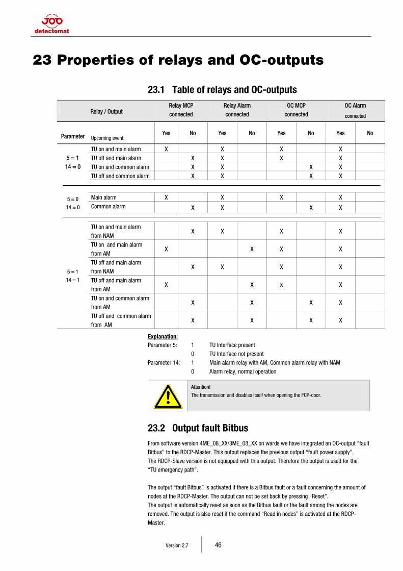
Version 2.7 46
23 Properties of relays and OC-outputs
23.1 Table of relays and OC-outputs
Relay / Output Relay MCP
connected
Relay Alarm
connected
OC MCP
connected
OC Alarm
connected
Parameter Upcoming event Yes No Yes No Yes No Yes No
TU on and main alarm X X X X
TU off and main alarm X X X X
TU on and common alarm X X X X
5 = 1
14 = 0
TU off and common alarm X X X X
Main alarm X X X X 5 = 0
14 = 0 Common alarm X X X X
TU on and main alarm
from NAM X X X X
TU on and main alarm
from AM X X X X
TU off and main alarm
from NAM X X X X
TU off and main alarm
from AM X X X X
TU on and common alarm
from AM X X X X
5 = 1
14 = 1
TU off and common alarm
from AM X X X X
Explanation: Parameter 5: 1 TU Interface present
0 TU Interface not present
Parameter 14: 1 Main alarm relay with AM, Common alarm relay with NAM
0 Alarm relay, normal operation
Attention!
The transmission unit disables itself when opening the FCP-door.
23.2 Output fault Bitbus From software version 4ME_08_XX/3ME_08_XX on wards we have integrated an OC-output “fault
Bitbus” to the RDCP-Master. This output replaces the previous output “fault power supply”.
The RDCP-Slave version is not equipped with this output. Therefore the output is used for the
“TU emergency path”.
The output “fault Bitbus” is activated if there is a Bitbus fault or a fault concerning the amount of
nodes at the RDCP-Master. The output can not be set back by pressing “Reset”.
The output is automatically reset as soon as the Bitbus fault or the fault among the nodes are
removed. The output is also reset if the command “Read in nodes” is activated at the RDCP-
Master.
15 Remote Display and Control Panel
Version 2.7 47
24 Notes for the operation of the detect
3004 (plus) in a network
Since the release of RDCP software version 4ME_08_xx / 3ME_08_xx / 4SE_08_xx / 3SE_08_xx
it is possible to integrate the fire control panel detect 3004 (plus) to the detectomat fire control and
FireX networks. It is possible to operate FCP’s of the type detect 3004 (plus), detect 3004 and
detect 3016 in a detectomat network.
We have listed the individual network components and necessary software versions in our
“Software compatibility list detect System 3000”. You find the list in the download centre of our
homepage in the section “Software”.
Please pay attention to the following information concerning the operation of the detect 3004
(plus) panel in the detectomat network.
To integrate the FCP detect 3004 (plus) into the network, the Master or Slave RDCP needs to be
equipped with the software version 4xE_08_xx or newer.
Indication of the first message at an alarm dependency
- Indication at the RDCP:
An intern alarm message and the red Alarm-LED will be triggered.
- Indication at the FCP detect 3004:
An intern alarm message will appear without triggering the red Alarm-LED
- Indication at the FCP detect 3004 (plus):
An intern alarm message will appear without triggering the red Alarm-LED
Alarm-Message counter
- A 1 alarm of an alarm dependency and revision alarm can be counted differently at a RDCP and
sub panel (detect 3004 (plus)). The reason is that the detect 3004 (plus) does not cpunt these
alarm as an alarm, the RDCP does.
Alarm delay in a network
Indication of the investigation time:
- The running investigation time is generally indicated at the RDCP-Master.
- Is there a customer text stored for the detector, then the investigation time will be indicated for
about 5 seconds. Then the customer text will be indicated.
- The running investigation time is not indicated at a RDCP-Slave version
Indication of the LED’s
- Indication at the RDCP: Delay on/off
- Indication at the detect 3004: Delay on/off, Investigation time started, Cancel delay
- Indication at the detect 3004 (plus) Delay on/off
Cancel delay:
- Procedure at the RDCP: The investigation time is cancelled by pressing
[ Delay On / Off ], entering the password and selecting
the subpanel. The delay is completely disabled.
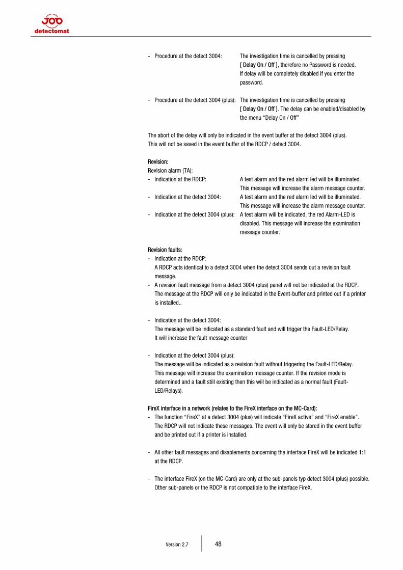
Version 2.7 48
- Procedure at the detect 3004: The investigation time is cancelled by pressing
[ Delay On / Off ], therefore no Password is needed.
If delay will be completely disabled if you enter the
password.
- Procedure at the detect 3004 (plus): The investigation time is cancelled by pressing
[ Delay On / Off ]. The delay can be enabled/disabled by
the menu “Delay On / Off”
The abort of the delay will only be indicated in the event buffer at the detect 3004 (plus).
This will not be saved in the event buffer of the RDCP / detect 3004.
Revision:
Revision alarm (TA):
- Indication at the RDCP: A test alarm and the red alarm led will be illuminated.
This message will increase the alarm message counter.
- Indication at the detect 3004: A test alarm and the red alarm led will be illuminated.
This message will increase the alarm message counter.
- Indication at the detect 3004 (plus): A test alarm will be indicated, the red Alarm-LED is
disabled. This message will increase the examination
message counter.
Revision faults:
- Indication at the RDCP:
A RDCP acts identical to a detect 3004 when the detect 3004 sends out a revision fault
message.
- A revision fault message from a detect 3004 (plus) panel will not be indicated at the RDCP.
The message at the RDCP will only be indicated in the Event-buffer and printed out if a printer
is installed..
- Indication at the detect 3004:
The message will be indicated as a standard fault and will trigger the Fault-LED/Relay.
It will increase the fault message counter
- Indication at the detect 3004 (plus):
The message will be indicated as a revision fault without triggering the Fault-LED/Relay.
This message will increase the examination message counter. If the revision mode is
determined and a fault still existing then this will be indicated as a normal fault (Fault-
LED/Relays).
FireX interface in a network (relates to the FireX interface on the MC-Card):
- The function “FireX” at a detect 3004 (plus) will indicate “FireX active” and “FireX enable”.
The RDCP will not indicate these messages. The event will only be stored in the event buffer
and be printed out if a printer is installed.
- All other fault messages and disablements concerning the interface FireX will be indicated 1:1
at the RDCP.
- The interface FireX (on the MC-Card) are only at the sub-panels typ detect 3004 (plus) possible.
Other sub-panels or the RDCP is not compatible to the interface FireX.
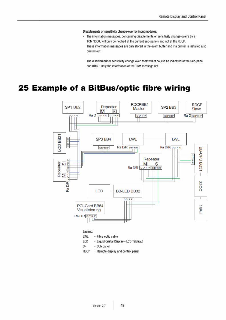
15 Remote Display and Control Panel
Version 2.7 49
Disablements or sensitivity change-over by input modules:
- The information messages, concerning disablements or sensitivity change-over’s by a
TCM 3300, will only be notified at the current sub-panels and not at the RDCP.
These information messages are only stored in the event buffer and if a printer is installed also
printed out.
The disablement or sensitivity change over itself will of course be indicated at the Sub-panel
and RDCP. Only the information of the TCM message not.
25 Example of a BitBus/optic fibre wiring
Legend:
LWL = Fibre optic cable
LCD = Liquid Cristal Display- (LCD Tableau)
SP = Sub panel
RDCP = Remote display and control panel