Embed Size (px)
Citation preview
Determination of Pipe and Bedding Combinations for Drainage Works (including Amendment No. 1 dated June 2015)
DN-DNG-03070 June 2015
Design Standards DN

TRANSPORT INFRASTRUCTURE IRELAND (TII) PUBLICATIONS
About TII
Transport Infrastructure Ireland (TII) is responsible for managing and improving the country’s
national road and light rail networks.
About TII Publications
TII maintains an online suite of technical publications, which is managed through the TII
Publications website. The contents of TII Publications is clearly split into ‘Standards’ and
‘Technical’ documentation. All documentation for implementation on TII schemes is collectively
referred to as TII Publications (Standards), and all other documentation within the system is
collectively referred to as TII Publications (Technical). This system replaces the NRA Design
Manual for Roads and Bridges (NRA DMRB) and the NRA Manual of Contract Documents for
Road Works (NRA MCDRW).
Document Attributes
Each document within TII Publications has a range of attributes associated with it, which allows
for efficient access and retrieval of the document from the website. These attributes are also
contained on the inside cover of each current document, for reference. For migration of
documents from the NRA and RPA to the new system, each current document was assigned with
new outer front and rear covers. Apart from the covers, and inside cover pages, the documents
contain the same information as previously within the NRA or RPA systems, including historical
references such as those contained within NRA DMRB and NRA MCDRW.
Document Attributes
TII Publication Title Determination of Pipe and Bedding Combinations for Drainage Works
(including Amendment No. 1 dated June 2015)
TII Publication
Number DN-DNG-03070
Activity Design (DN) Document Set Standards
Stream Drainage (DNG) Publication Date June 2015
Document
Number
03070 Historical
Reference
NRA HD 140
NRA DMRB and MCDRW References
For all documents that existed within the NRA DMRB or the NRA MCDRW prior to the launch of
TII Publications, the NRA document reference used previously is listed above under ‘historical
reference’. The TII Publication Number also shown above now supersedes this historical
reference. All historical references within this document are deemed to be replaced by the TII
Publication Number. For the equivalent TII Publication Number for all other historical
references contained within this document, please refer to the TII Publications website.
Determination of Pipe and Bedding Combinations for Drainage Works
(including Amendment No. 1)
Volume 4 Section 2 Part 5
NRA HD 140/15
March 2015
(including Amendment No. 1, dated June 2015)
St. Martin’s House, Waterloo Road, Dublin 4 Tel: +353 1 660 2511 Fax +353 1 668 0009 Email: [email protected] Web: www.nra.ie
Summary:
This Standard describes the method of selecting suitable combinations of drainage pipes and bedding types to meet given loading requirements.
Published by National Roads Authority, Dublin 2015
NRA DESIGN MANUAL FOR ROADS AND BRIDGES
VOLUME 4 GEOTECHNICS AND DRAINAGE
SECTION 2 DRAINAGE
PART 5
NRA HD 140/15
DETERMINATION OF PIPE AND BEDDING COMBINATIONS FOR DRAINAGE WORKS (INCLUDING AMENDMENT NO. 1)
Contents
Chapter
1. Introduction
2. Design Considerations
3. Worked Example
4. Specification Requirements
5. References
6. Enquiries
APPENDIX A: Types of Pipe to Which Charts are Applicable
APPENDIX B: Charts of Bedding/Pipe Combinations
APPENDIX C: Group Numbers for Determining Allowable
Pipes
Amendment No. 1
March 2015 i
National Roads Authority Volume 4 Section 2 Design Manual for Roads and Bridges Part 5 NRA HD 140/15
(including Amendment No, 1)
1. INTRODUCTION General
1.1 The NRA Specification for Road Works (NRA SRW) permits a range of pipes of different material properties to be used for drainage works in roads. The NRA Road Construction Details (NRA RCD) also allow a choice in the method of bedding pipes where the degree of structural support given to the pipe when it is laid in trench varies. In general, not all possible combinations of pipe and bedding selected from the permitted options for each will necessarily be suitable for a particular design and permitted combinations have therefore to be specified for each contract.
1.2 The 2015 revision of the NRA’s drainage standards was precipitated by post-doctoral research carried out under the NRA’s Research Fellowship Programme and mentored by the NRA’s Environment Unit. This research looked at the impacts of national road drainage systems on both surface and ground water. The research concluded that the NRA’s drainage standards needed to be expanded to promote the use of sustainable drainage systems and to maximise environmental benefits. A report entitled Drainage Design for National Road Schemes – Sustainable Drainage Options (NRA, 2014) documents this research and provides useful background reading to the NRA’s drainage standards. This document is available at: nrastandards.nra.ie/latest/other-nra-documents
Scope
1.3 The charts presented in this Standard shall be used to select the combinations of type of pipe and bedding from the permitted alternatives in the NRA Specification for Road Works and Road Construction Details to meet given loading requirements. They are a revision of the charts previously published in UK Highways Agency HA 40 and take into account updates of British Standards and Euronorms for some pipes and loading patterns in accordance with BS 5400: Part 2 as implemented by NRA BD 37 Loads for Road Bridges. Charts for an additional category of loading for pipes laid in filter drains have been included.
1.4 The range of pipes included in the charts is listed in Appendix A. The charts may be applicable for the design of pipe types not covered in this Standard but the designer should satisfy themselves that the relevant physical properties are comparable to those listed. Chapter 2 of this Standard outlines the design basis for deriving the charts.
1.5 The types of pipe bedding that are covered are those shown in RCD/500/20 and RCD/500/21.
1.6 The charts are intended for the widest range of pipe bedding combinations and are based on the worst case scenario from a range of manufactured pipe thicknesses, possible trench widths and bedding factors and are therefore conservative. Designers should, when justified, consider the merits of individual designs to suit local conditions. For example when the trench width can be closely controlled and the pipe outside diameter is accurately known, a specific design check may allow a pipe to be safely used outside the tabulated depth range or alternatively permit a lower strength pipe and/or bedding to be used at the given depth.
1.7 This Standard does not cover hydraulic design requirements for pipes; refer to NRA HD 33 Drainage Systems for National Roads.
1.8 The principles outlined in this Standard apply to all National Roads projects.
March 2015 1
National Roads Authority Volume 4 Section 2 Design Manual for Roads and Bridges Part 5 NRA HD 140/15
(including Amendment No, 1) Implementation
1.9 1This Standard shall be used forthwith on all schemes for the construction and/or improvement of national roads except where the scheme has received, prior to publication of this Standard, its statutory approvals to allow it to proceed. If this exception applies, the standard to be used may be either this current Standard or the Standard applicable preceding the March 2015 version of the Standard. Where the previous Standard is to be used, Designers Organisations shall confirm this by e-mail to the Standards Section of the National Roads Authority at [email protected].
1 Amended as per Amendment No. 1, item 1
March 2015 2
National Roads Authority Volume 4 Section 2 Design Manual for Roads and Bridges Part 5 NRA HD 140/15
(including Amendment No, 1)
2. DESIGN CONSIDERATIONS Range of Bedding Types
2.1 Methods of bedding pipes are shown in RCD/500/20 for filter drains and RCD/500/21 for carrier drains. These different beddings provide varying degrees of support to the pipe. In the case of combined surface and sub-surface drains the granular bedding and surround additionally functions as a filter medium. Not all possibilities that would give satisfactory bedding are included in Series 500 of NRA RCD; the choice has been restricted to save granular material and to combinations most likely to be of use. Bed types A, B, F, N and S in RCD/500/21 are for use with rigid pipes and bed types S and T with flexible pipes. Type T bedding for rigid pipes is less likely to be economic for the same degree of support. Type Z is for use with any type of pipe for permanent protection against mechanical damage, for example when subsequent excavations are required alongside the pipeline, for pipe junctions and where remedial measures are required. It converts a relatively flexible pipeline into a rigid beam of low flexural strength, susceptible to damage by differential settlement and is uneconomic to use except where essential. Flexibly jointed pipes shall have a compressible filler to break the Type Z surround at every joint or second joint for short pipes. All bed types shown in RCD/500/20 are suitable for both rigid and flexible pipes.
The specification requirements for bedding, backfill material and construction are given in the Series 500 of NRA SRW.
Loading on Pipes
2.2 The design charts cater for three categories of loading conditions, which include imposed surface loads together with soil and water loads as appropriate. The latter have been considered only for pipes greater than 600mm diameter.
a) Main road loading is applicable to pipes under pavements including cross drains and for pipes in verges where heavy loads may occur. It consists of 8 wheel loads each of 112.5 kN including impact factor, in the HB loading pattern corresponding to 45 units of HB loading to BS 5400: Part 2 as implemented by NRA BD 37.
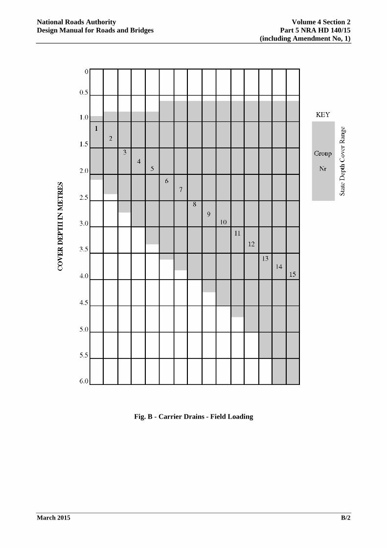
b) Field loading is applicable to fields, gardens and lightly trafficked access tracks. It consists of two wheels 1.0m apart, each of a static load of 30 kN with an impact factor of 2.0, giving a total load for each wheel of 60 kN.
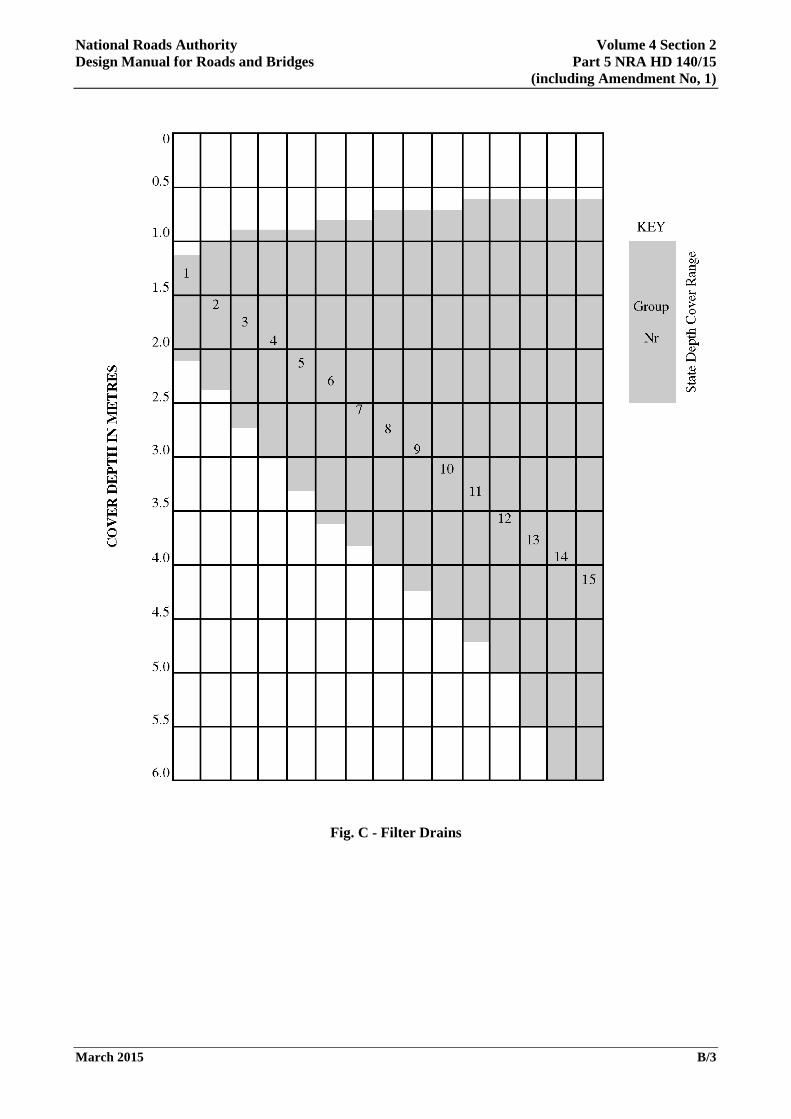
c) Filter drain loading is applicable to pipes in filter drains in verges and central reserves. It corresponds to the outer verge loading specified in BS 5400: Part 2 as implemented by NRA BD 37 with 30 units of HB loading, each wheel load being 62.5 kN. Only two wheel loads are considered but with an increased impact factor of 1.4 giving a total load for each wheel of 87.5 kN. Filter drains not immediately adjacent to the carriageway may, if appropriate, be designed for field loads.
Loads during Construction
2.3 Pipes laid under and adjacent to roads are likely to be subject to higher loads during construction than in service. The charts given in this Standard are not applicable to this situation and a specific design check shall be required and documented. The following safeguards may be considered when pipelines have to be crossed by construction traffic and plant:
March 2015 3
National Roads Authority Volume 4 Section 2 Design Manual for Roads and Bridges Part 5 NRA HD 140/15
(including Amendment No, 1)
a) Temporary bridging or slabbing or increasing the cover over shallow pipes with suitable material to be at least 1m for general construction traffic or 2m where a haul road is constructed or motorised scrapers are used.
b) Provision of a stronger design for the pipe and bed combination. Wheel loads of 180 kN in the HB pattern can be used to achieve a strength suitable for general construction traffic. Wheel loads of 280 kN are necessary for haul roads and motorised scrapers. More detailed advice is given in Reference 5.4.
Settlement
2.4 Pipes in highly compressible soils shall, where feasible, be avoided. Where this is not possible, only granular beds (types B, F and S) shall be permitted and the use of a geotextile filter on the floor of the trench should be considered to prevent contamination of the bedding material.
Rigid Pipe Design
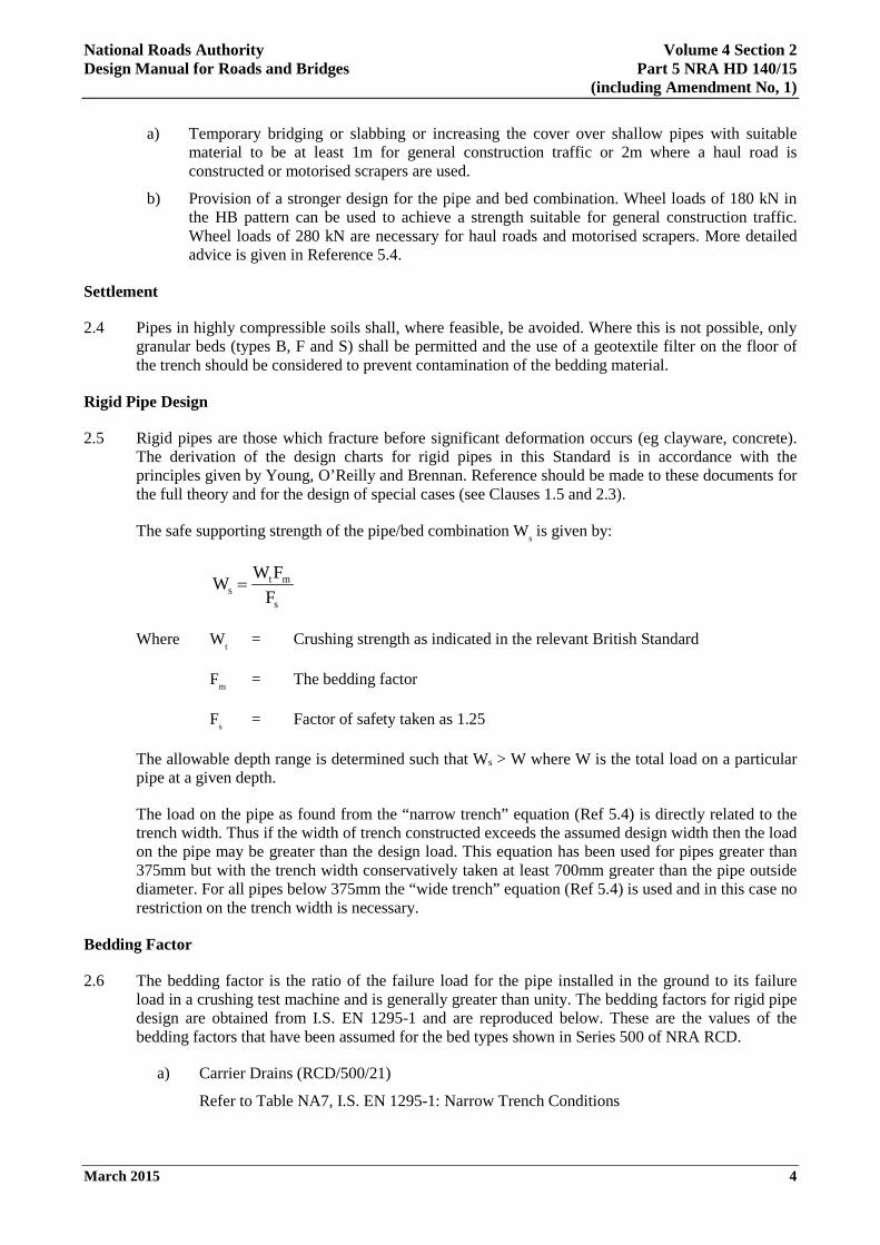
2.5 Rigid pipes are those which fracture before significant deformation occurs (eg clayware, concrete). The derivation of the design charts for rigid pipes in this Standard is in accordance with the principles given by Young, O’Reilly and Brennan. Reference should be made to these documents for the full theory and for the design of special cases (see Clauses 1.5 and 2.3).
The safe supporting strength of the pipe/bed combination Ws is given by:
W W F
Fst m
s
=
Where Wt = Crushing strength as indicated in the relevant British Standard
Fm = The bedding factor
Fs = Factor of safety taken as 1.25
The allowable depth range is determined such that Ws > W where W is the total load on a particular pipe at a given depth.
The load on the pipe as found from the “narrow trench” equation (Ref 5.4) is directly related to the trench width. Thus if the width of trench constructed exceeds the assumed design width then the load on the pipe may be greater than the design load. This equation has been used for pipes greater than 375mm but with the trench width conservatively taken at least 700mm greater than the pipe outside diameter. For all pipes below 375mm the “wide trench” equation (Ref 5.4) is used and in this case no restriction on the trench width is necessary.
Bedding Factor
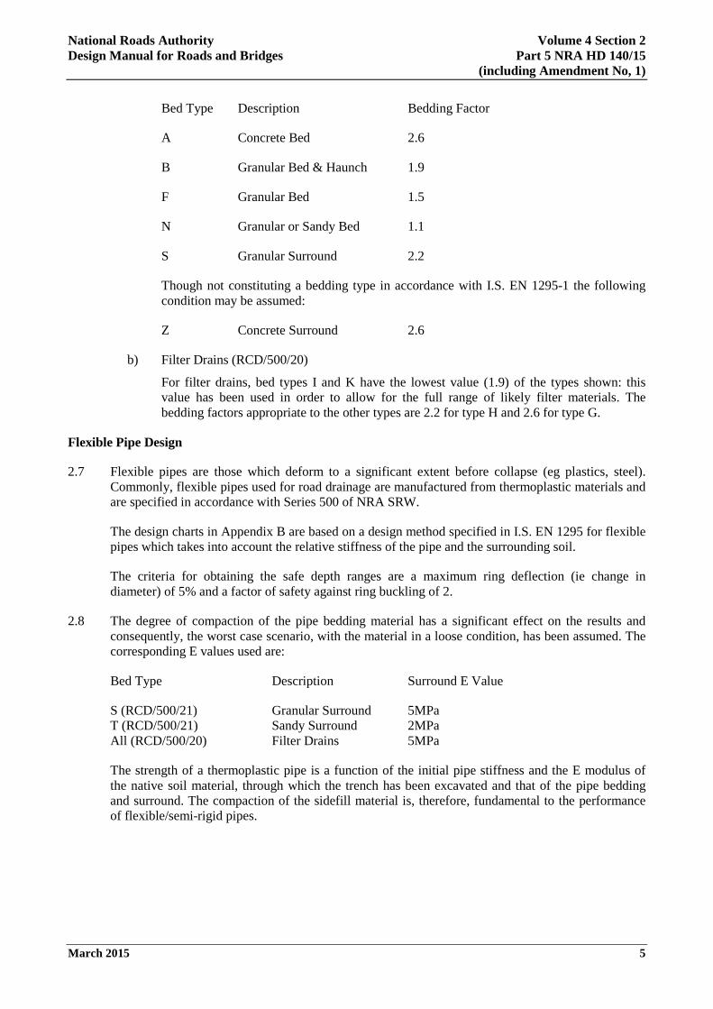
2.6 The bedding factor is the ratio of the failure load for the pipe installed in the ground to its failure load in a crushing test machine and is generally greater than unity. The bedding factors for rigid pipe design are obtained from I.S. EN 1295-1 and are reproduced below. These are the values of the bedding factors that have been assumed for the bed types shown in Series 500 of NRA RCD.
a) Carrier Drains (RCD/500/21)
Refer to Table NA7, I.S. EN 1295-1: Narrow Trench Conditions
March 2015 4
National Roads Authority Volume 4 Section 2 Design Manual for Roads and Bridges Part 5 NRA HD 140/15
(including Amendment No, 1)
Bed Type Description Bedding Factor
A Concrete Bed 2.6
B Granular Bed & Haunch 1.9
F Granular Bed 1.5
N Granular or Sandy Bed 1.1
S Granular Surround 2.2
Though not constituting a bedding type in accordance with I.S. EN 1295-1 the following condition may be assumed:
Z Concrete Surround 2.6
b) Filter Drains (RCD/500/20)
For filter drains, bed types I and K have the lowest value (1.9) of the types shown: this value has been used in order to allow for the full range of likely filter materials. The bedding factors appropriate to the other types are 2.2 for type H and 2.6 for type G.
Flexible Pipe Design
2.7 Flexible pipes are those which deform to a significant extent before collapse (eg plastics, steel). Commonly, flexible pipes used for road drainage are manufactured from thermoplastic materials and are specified in accordance with Series 500 of NRA SRW.
The design charts in Appendix B are based on a design method specified in I.S. EN 1295 for flexible pipes which takes into account the relative stiffness of the pipe and the surrounding soil.
The criteria for obtaining the safe depth ranges are a maximum ring deflection (ie change in diameter) of 5% and a factor of safety against ring buckling of 2.
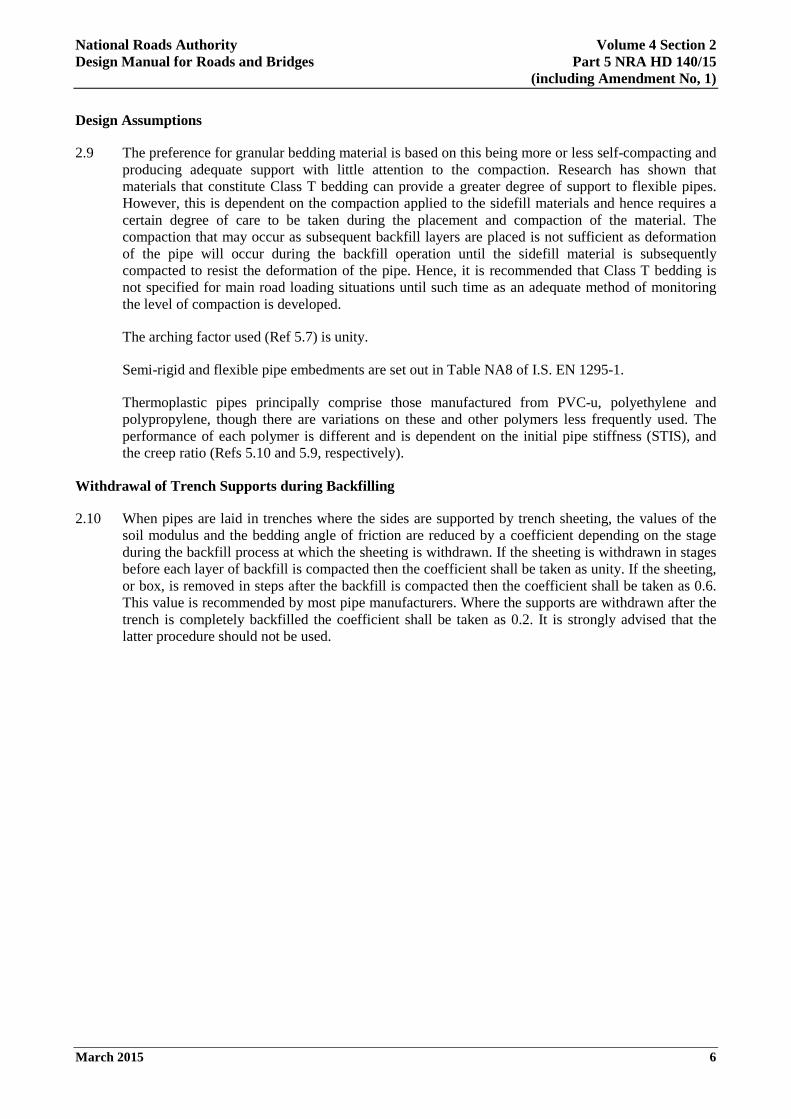
2.8 The degree of compaction of the pipe bedding material has a significant effect on the results and consequently, the worst case scenario, with the material in a loose condition, has been assumed. The corresponding E values used are:
Bed Type Description Surround E Value
S (RCD/500/21) Granular Surround 5MPa T (RCD/500/21) Sandy Surround 2MPa All (RCD/500/20) Filter Drains 5MPa
The strength of a thermoplastic pipe is a function of the initial pipe stiffness and the E modulus of the native soil material, through which the trench has been excavated and that of the pipe bedding and surround. The compaction of the sidefill material is, therefore, fundamental to the performance of flexible/semi-rigid pipes.
March 2015 5
National Roads Authority Volume 4 Section 2 Design Manual for Roads and Bridges Part 5 NRA HD 140/15
(including Amendment No, 1)
Design Assumptions
2.9 The preference for granular bedding material is based on this being more or less self-compacting and producing adequate support with little attention to the compaction. Research has shown that materials that constitute Class T bedding can provide a greater degree of support to flexible pipes. However, this is dependent on the compaction applied to the sidefill materials and hence requires a certain degree of care to be taken during the placement and compaction of the material. The compaction that may occur as subsequent backfill layers are placed is not sufficient as deformation of the pipe will occur during the backfill operation until the sidefill material is subsequently compacted to resist the deformation of the pipe. Hence, it is recommended that Class T bedding is not specified for main road loading situations until such time as an adequate method of monitoring the level of compaction is developed.
The arching factor used (Ref 5.7) is unity.
Semi-rigid and flexible pipe embedments are set out in Table NA8 of I.S. EN 1295-1.
Thermoplastic pipes principally comprise those manufactured from PVC-u, polyethylene and polypropylene, though there are variations on these and other polymers less frequently used. The performance of each polymer is different and is dependent on the initial pipe stiffness (STIS), and the creep ratio (Refs 5.10 and 5.9, respectively).
Withdrawal of Trench Supports during Backfilling
2.10 When pipes are laid in trenches where the sides are supported by trench sheeting, the values of the soil modulus and the bedding angle of friction are reduced by a coefficient depending on the stage during the backfill process at which the sheeting is withdrawn. If the sheeting is withdrawn in stages before each layer of backfill is compacted then the coefficient shall be taken as unity. If the sheeting, or box, is removed in steps after the backfill is compacted then the coefficient shall be taken as 0.6. This value is recommended by most pipe manufacturers. Where the supports are withdrawn after the trench is completely backfilled the coefficient shall be taken as 0.2. It is strongly advised that the latter procedure should not be used.
March 2015 6
National Roads Authority Volume 4 Section 2 Design Manual for Roads and Bridges Part 5 NRA HD 140/15
(including Amendment No, 1)
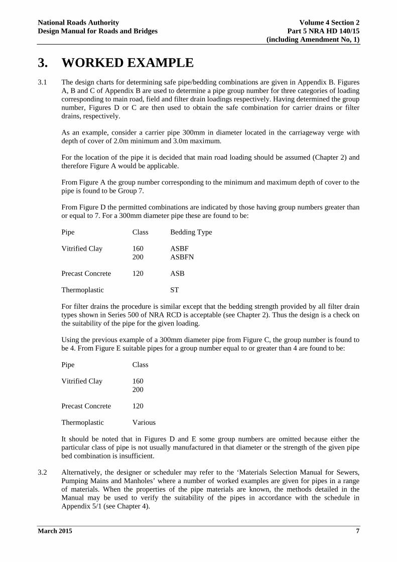
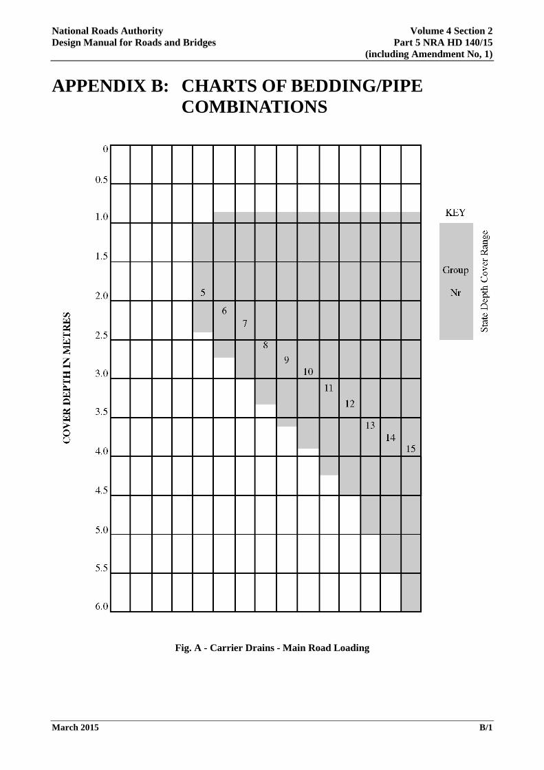
3. WORKED EXAMPLE 3.1 The design charts for determining safe pipe/bedding combinations are given in Appendix B. Figures
A, B and C of Appendix B are used to determine a pipe group number for three categories of loading corresponding to main road, field and filter drain loadings respectively. Having determined the group number, Figures D or C are then used to obtain the safe combination for carrier drains or filter drains, respectively.
As an example, consider a carrier pipe 300mm in diameter located in the carriageway verge with depth of cover of 2.0m minimum and 3.0m maximum.
For the location of the pipe it is decided that main road loading should be assumed (Chapter 2) and therefore Figure A would be applicable.
From Figure A the group number corresponding to the minimum and maximum depth of cover to the pipe is found to be Group 7.
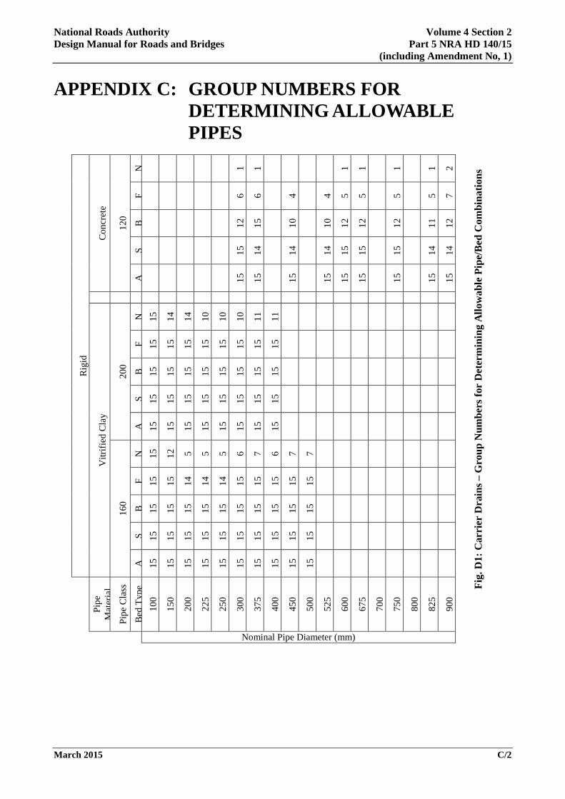
From Figure D the permitted combinations are indicated by those having group numbers greater than or equal to 7. For a 300mm diameter pipe these are found to be:
Pipe Class Bedding Type
Vitrified Clay 160 ASBF 200 ASBFN
Precast Concrete 120 ASB
Thermoplastic ST
For filter drains the procedure is similar except that the bedding strength provided by all filter drain types shown in Series 500 of NRA RCD is acceptable (see Chapter 2). Thus the design is a check on the suitability of the pipe for the given loading.
Using the previous example of a 300mm diameter pipe from Figure C, the group number is found to be 4. From Figure E suitable pipes for a group number equal to or greater than 4 are found to be:
Pipe Class
Vitrified Clay 160 200
Precast Concrete 120
Thermoplastic Various
It should be noted that in Figures D and E some group numbers are omitted because either the particular class of pipe is not usually manufactured in that diameter or the strength of the given pipe bed combination is insufficient.
3.2 Alternatively, the designer or scheduler may refer to the ‘Materials Selection Manual for Sewers, Pumping Mains and Manholes’ where a number of worked examples are given for pipes in a range of materials. When the properties of the pipe materials are known, the methods detailed in the Manual may be used to verify the suitability of the pipes in accordance with the schedule in Appendix 5/1 (see Chapter 4).
March 2015 7

National Roads Authority Volume 4 Section 2 Design Manual for Roads and Bridges Part 5 NRA HD 140/15
(including Amendment No, 1)
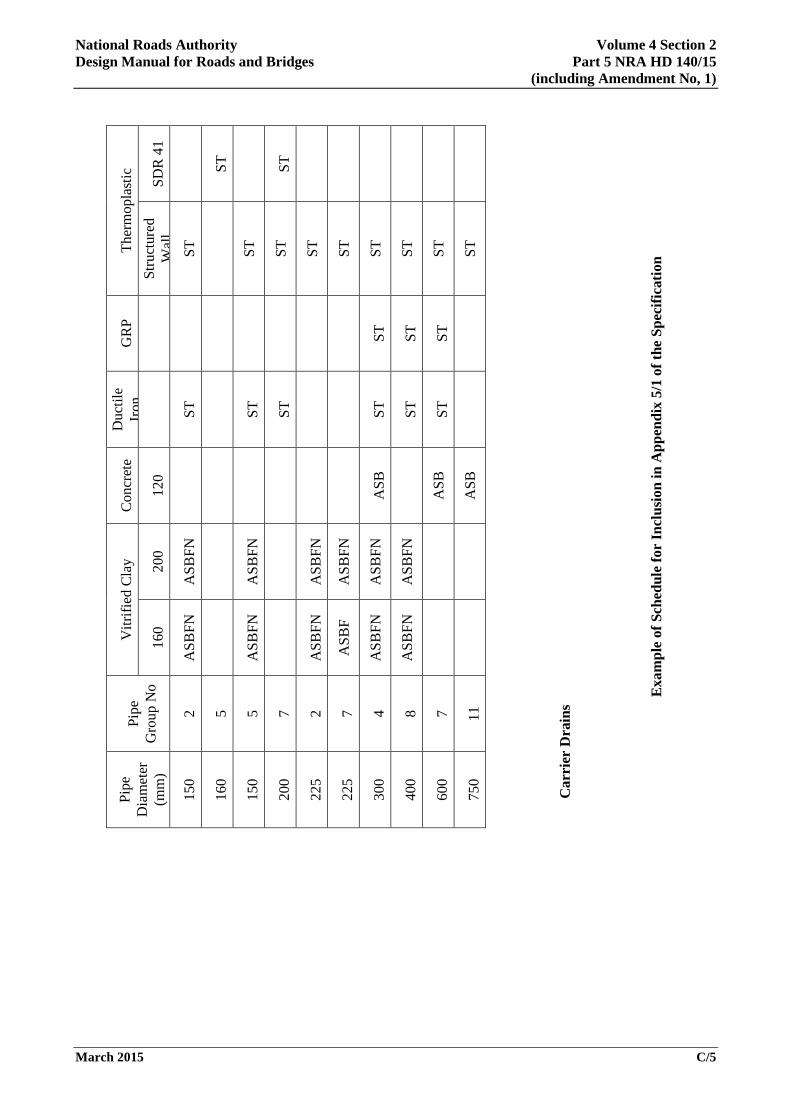
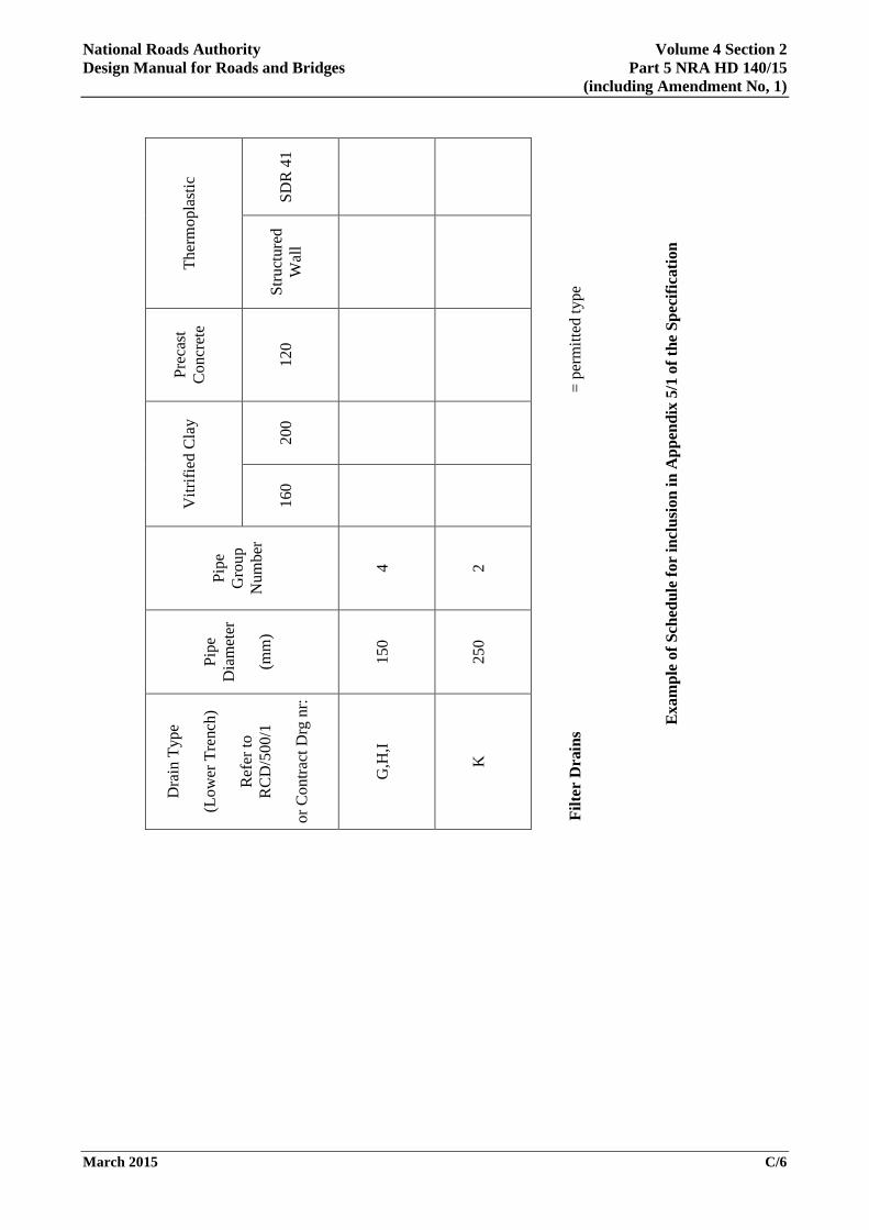
4. SPECIFICATION REQUIREMENTS 4.1 The NRA Specification for Road Works requires contract-specific information to be provided by the
designers. The permitted pipe/bed combinations for carrier drains and the permitted pipe types and drain types for filter drains shall be set out in a schedule which will form part of Appendix 5/1 in Series 500 of the Specification. An example of a format for this schedule is given in Appendix C.
March 2015 8
National Roads Authority Volume 4 Section 2 Design Manual for Roads and Bridges Part 5 NRA HD 140/15
(including Amendment No, 1)
5. REFERENCES 5.1 NRA Manual of Contract Documents for Road Works (NRA MCDRW)
a) NRA Specification for Road Works (NRA SRW) (MCDRW 1)
b) Notes for Guidance on the Specification for Road Works (NRA NGSRW) (MCDRW 2)
c) Road Construction Details (NRA RCD) (MCDRW 4)
5.2 NRA Design Manual for Roads and Bridges (NRA DMRB)
a) NRA BD 37 Loads for Road Bridges
b) NRA HD 33 Drainage Systems for National Roads
5.3 Materials Selection Manual for Sewers, Pumping Mains and Manholes. Water Services Association, London 1993.
5.4 A Guide to Design Loadings for Buried Rigid Pipes. O C Young and M P O’Reilly. Transport and Road Research Laboratory. Department of Transport. HMSO, 1983.
5.5 Simplified Tables of External Loads on Buried Pipelines. O C Young, G Brennan and M P O’Reilly. Transport and Road Research Laboratory. Department of Transport, HMSO. 1986.
5.6 The Development of a New Design Method for Buried Flexible Pipes. J E Gumbel, M P O’Reilly, L M Lake and D R Carder. Proceedings Europipe 82, Basle (Access Conferences London 1982).
5.7 A New General Design Method for Buried Flexible Pipes. Mott, Hay and Anderson. (Unpublished TRRL Ref No CON/6102/21).
5.8 UNE ENV 1046: 2002. Plastics piping and ducting systems - Systems Outside Building Structures for the Conveyance of Water or Sewage - Practices for Installation Above and Below Ground.
5.9 I.S. EN ISO 9967: 2007 Thermoplastics pipes - Determination of Creep Ratio. National Standards Authority of Ireland.
5.10 I.S. EN ISO 9969: 2007. Thermoplastic pipes - Determination of Ring Stiffness. National Standards Authority of Ireland.
5.11 I.S. EN 1295-1: 1998. Structural Design of Buried Pipelines Under Various Conditions of Loading - Part 1: General Requirements. British Standards Institution.
5.12 I.S. EN 1610: 1998. Construction and Testing of Drains and Sewers. National Standards Authority of Ireland.
5.13 I.S. EN 598: 2007+A1: 2009. Ductile Iron Pipes, Fittings, Accessories and their Joints for Sewerage Applications - Requirements and Test Methods. National Standards Authority of Ireland.
5.14 Drainage Design for National Road Schemes – Sustainable Drainage Options. National Roads Authority. 2014.
March 2015 9

National Roads Authority Volume 4 Section 2 Design Manual for Roads and Bridges Part 5 NRA HD 140/15
(including Amendment No, 1)
6. ENQUIRIES 6.1 All technical enquiries or comments on this document, or any of the documents listed as forming part
of the NRA DMRB, should be sent by e-mail to [email protected], addressed to the following:
Head of Network Management, Engineering Standards & Research National Roads Authority St Martin’s House Waterloo Road Dublin 4
…………………………...
Pat Maher Head of Network Management,
Engineering Standards & Research
March 2015 10
National Roads Authority Volume 4 Section 2 Design Manual for Roads and Bridges Part 5 NRA HD 140/15
(including Amendment No, 1)
National Roads Authority
Design Manual for Roads and Bridges (NRA DMRB)
Amendment No. 1 (June 2015) to NRA Design Manual for Roads and
Bridges Volume 4, Section 2, Part 5 NRA HD 140 - Determination of Pipe and Bedding Combinations for
Drainage Works
Dated March 2015
The NRA Design Manual for Roads and Bridges (NRA DMRB) NRA HD 140, dated March 2015 is amended as follows:-
1. Page 2, Clause 1.9
Implementation Clause 1.9 is amended
March 2015 11
National Roads Authority Volume 4 Section 2 Design Manual for Roads and Bridges Part 5 NRA HD 140/15
(including Amendment No, 1)
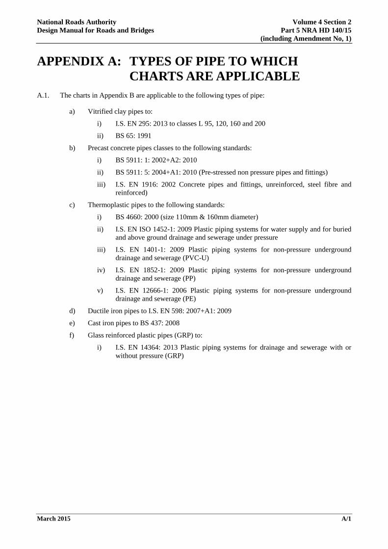
APPENDIX A: TYPES OF PIPE TO WHICH CHARTS ARE APPLICABLE
A.1. The charts in Appendix B are applicable to the following types of pipe:
a) Vitrified clay pipes to:
i) I.S. EN 295: 2013 to classes L 95, 120, 160 and 200
ii) BS 65: 1991
b) Precast concrete pipes classes to the following standards:
i) BS 5911: 1: 2002+A2: 2010
ii) BS 5911: 5: 2004+A1: 2010 (Pre-stressed non pressure pipes and fittings)
iii) I.S. EN 1916: 2002 Concrete pipes and fittings, unreinforced, steel fibre and reinforced)
c) Thermoplastic pipes to the following standards:
i) BS 4660: 2000 (size 110mm & 160mm diameter)
ii) I.S. EN ISO 1452-1: 2009 Plastic piping systems for water supply and for buried and above ground drainage and sewerage under pressure
iii) I.S. EN 1401-1: 2009 Plastic piping systems for non-pressure underground drainage and sewerage (PVC-U)
iv) I.S. EN 1852-1: 2009 Plastic piping systems for non-pressure underground drainage and sewerage (PP)
v) I.S. EN 12666-1: 2006 Plastic piping systems for non-pressure underground drainage and sewerage (PE)
d) Ductile iron pipes to I.S. EN 598: 2007+A1: 2009
e) Cast iron pipes to BS 437: 2008
f) Glass reinforced plastic pipes (GRP) to:
i) I.S. EN 14364: 2013 Plastic piping systems for drainage and sewerage with or without pressure (GRP)
March 2015 A/1
National Roads Authority Volume 4 Section 2 Design Manual for Roads and Bridges Part 5 NRA HD 140/15
(including Amendment No, 1)
APPENDIX B: CHARTS OF BEDDING/PIPE COMBINATIONS
Fig. A - Carrier Drains - Main Road Loading
March 2015 B/1
National Roads Authority Volume 4 Section 2 Design Manual for Roads and Bridges Part 5 NRA HD 140/15
(including Amendment No, 1)
Fig. B - Carrier Drains - Field Loading
March 2015 B/2
National Roads Authority Volume 4 Section 2 Design Manual for Roads and Bridges Part 5 NRA HD 140/15
(including Amendment No, 1)
Fig. C - Filter Drains
March 2015 B/3
National Roads Authority Volume 4 Section 2 Design Manual for Roads and Bridges Part 5 NRA HD 140/15
(including Amendment No, 1)
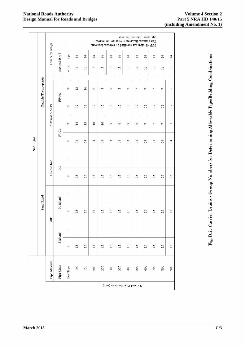
APPENDIX C: GROUP NUMBERS FOR DETERMINING ALLOWABLE PIPES
Rig
id
Con
cret
e
120
N
1 1 1 1 1 1 2
Fig.
D1:
Car
rier
Dra
ins –
Gro
up N
umbe
rs fo
r D
eter
min
ing
Allo
wab
le P
ipe/
Bed
Com
bina
tions
F 6 6 4 4 5 5 5 5 7
B
12
15 10 10
12
12 12 11
12
S 15
14 14 14
15
15 15 14
14
A
15
15 15 15
15
15 15 15
15
Vitr
ified
Cla
y
200
N
15
14
14
10
10
10
11
11
F 15
15
15
15
15
15
15
15
B
15
15
15
15
15
15
15
15
S 15
15
15
15
15
15
15
15
A
15
15
15
15
15
15
15
15
160
N
15
12
5 5 5 6 7 6 7 7
F 15
15
14
14
14
15
15
15
15
15
B
15
15
15
15
15
15
15
15
15
15
S 15
15
15
15
15
15
15
15
15
15
A
15
15
15
15
15
15
15
15
15
15
Pipe
M
ater
ial
Pipe
Cla
ss
Bed
Typ
e 10
0
150
200
225
250
300
375
400
450
500
525
600
675
700
750
800
825
900
Nominal Pipe Diameter (mm)
March 2015 C/2
National Roads Authority Volume 4 Section 2 Design Manual for Roads and Bridges Part 5 NRA HD 140/15
(including Amendment No, 1)
March 2015 C/3

National Roads Authority Volume 4 Section 2 Design Manual for Roads and Bridges Part 5 NRA HD 140/15
(including Amendment No, 1)
Pipe Material Vitrified Clay Concrete Thermoplastic
Pipe Class 160 200 120 Structured
Wall SDR 41
Nom
inal
Pip
e D
iam
eter
(mm
)
100 15 15 15 100
Nom
inal
Pip
e D
iam
eter
(mm
)
150 15 15 15 15 110
225 15 15 15 150
250 15 15 15 15 160
300 15 15 15 15 15 200
350 15 225
375 15 15 15 15 250
400 15 15 15 260
450 15 15 15 15 300
500 11 15 15 360
525 15 15 400
600 11 15 15 450
675 15 15 500
700 15 600
750 15 15 700
800 15 750
825 15 15 900
900 15
Fig. E: Filter Drains – Group Numbers for Determining Allowable Pipes
March 2015 C/4
National Roads Authority Volume 4 Section 2 Design Manual for Roads and Bridges Part 5 NRA HD 140/15
(including Amendment No, 1)
Ther
mop
last
ic
SDR
41
ST ST
Exa
mpl
e of
Sch
edul
e fo
r In
clus
ion
in A
ppen
dix
5/1
of th
e Sp
ecifi
catio
n
Stru
ctur
ed
Wal
l ST
ST
ST
ST
ST
ST
ST
ST
ST
GR
P ST
ST
ST
Duc
tile
Iron
ST
ST
ST ST
ST
ST
Con
cret
e
120
ASB
ASB
ASB
Vitr
ified
Cla
y 200
ASB
FN
ASB
FN
ASB
FN
ASB
FN
ASB
FN
ASB
FN
160
ASB
FN
ASB
FN
ASB
FN
ASB
F
ASB
FN
ASB
FN
Pipe
G
roup
No
2 5 5 7 2 7 4 8 7 11
Car
rier
Dra
ins
Pipe
D
iam
eter
(m
m)
150
160
150
200
225
225
300
400
600
750
March 2015 C/5
National Roads Authority Volume 4 Section 2 Design Manual for Roads and Bridges Part 5 NRA HD 140/15
(including Amendment No, 1)
Ther
mop
last
ic
SDR
41
= pe
rmitt
ed ty
pe
Exa
mpl
e of
Sch
edul
e fo
r in
clus
ion
in A
ppen
dix
5/1
of th
e Sp
ecifi
catio
n
Stru
ctur
ed
Wal
l
Prec
ast
Con
cret
e
120
Vitr
ified
Cla
y
200
160
Pipe
G
roup
N
umbe
r
4 2
Pipe
D
iam
eter
(mm
)
150
250
Filte
r D
rain
s
Dra
in T
ype
(Low
er T
renc
h)
Ref
er to
R
CD
/500
/1
or C
ontra
ct D
rg n
r:
G,H
,I
K
March 2015 C/6

Ionad Ghnó Gheata na
Páirce,
Stráid Gheata na Páirce, Baile Átha Cliath 8, Éire
www.tii.ie
+353 (01) 646 3600
Parkgate Business Centre,
Parkgate Street,
Dublin 8, Ireland
+353 (01) 646 3601