Embed Size (px)
Citation preview
DETERMINATION OF SEISMIC PERFORMANCE FACTORS FOR CLT SHEAR WALL SYSTEMS M. Omar Amini1, John W. van de Lindt2, Douglas Rammer3, Shiling Pei4, Philip Line5, Marjan Popovski6 ABSTRACT: This paper presents selected results of connector testing and wall testing which were part of a Forest Products Lab-funded project undertaken at Colorado State University in an effort to determine seismic performance factors for cross laminated timber (CLT) shear walls in the United States. Archetype development, which is required as part of the process, is also discussed. Connector tests were performed on generic angle brackets which were tested under shear and uplift and performed as expected with consistent nail withdrawal observed. Quasi-static cyclic tests were conducted on CLT shear walls to systematically investigate the effects of various parameters. Boundary constraints and gravity loading were both found to have a beneficial effect on the wall performance, i.e. higher strength and deformation capacity. Specific gravity also had a significant effect on wall behaviour while CLT thickness was less influential. Higher aspect ratio panels (4:1) demonstrated lower stiffness and substantially larger deformation capacity compared to moderate aspect ratio panels (2:1). However, based on the test results there is likely a lower bound of 2:1 for aspect ratio where it ceases to have any beneficial effect on wall behaviour. This is likely due to the transition from the dominant rocking behaviour to sliding behaviour. KEYWORDS: Cross-laminated timber (CLT), seismic performance factors, FEMA P695 methodology, ASCE7 1 INTRODUCTION 123
From their early development in Europe, Cross Laminated Timber (CLT) buildings were mainly constructed in low to moderate seismic regions. However, recent research efforts in Europe, North
1 (Contact Author) Ph.D. Candidate, Department of Civil and Environmental Engineering, Colorado State University, Fort Collins, CO 80523, USA. E-mail: [email protected] 2 George T. Abell Distinguished Professor in Infrastructure, Department of Civil and Environmental Engineering, Colorado State University, Fort Collins, CO 80523, USA. E-mail: [email protected] 3 Research General Engineer, Forest Products Laboratory, One Gifford Pinchot Drive, Madison, WI 53726, USA. E-mail: [email protected] 4 Assistant Professor, Department of Civil and Environmental Engineering, Colorado School of Mines, Golden, CO 80401 USA. E-mail: [email protected] 5 Director, Structural Engineering, American Wood Council, 222 Catoctin Circle SE, Suite 201, Leesburg, VA 20175, USA. E-mail: [email protected] 6 Principal Scientist and Quality Manager, Advanced Building Systems Department, FPInnovations, 2665 East Mall, Vancouver BC, Canada, V6T 1Z4. E-mail: [email protected]
America and Japan have been geared towards investigating the behaviour and application of CLT systems under high seismic loading. In the meantime, CLT is beginning to find its way into the US construction market and many researchers believe that it can serve to fill a gap for certain regions of the US; specifically, the mid-rise condominium, commercial, and mixed-use building market in seismic regions. CLT based Seismic Force Resisting Systems (SFRS) are not recognized in the US design codes and therefore CLT use for seismic force resistance can only be recognized through alternative methods. This approach, however, is more costly and more complicated, making CLT less competitive against other conventional structural systems. A USDA (United State Department of Agriculture) Forest Products Laboratory (FPL) funded research project is currently underway at Colorado State University (CSU); the purpose of which is to determine seismic performance factors for CLT as a SFRS. The study utilizes the FEMA P695 [1] methodology that provides a systematic approach consisting of nonlinear static and dynamic analyses. The procedure also takes into account uncertainties inherent in test data and modelling methods. Various phases of the project consist of development of the archetypes, design methodology, testing, modelling, and analyses. This paper presents results from the experimental phases and archetype
development aspect of the project. The testing phase of the project includes three main parts, namely (i) connector testing (ii) CLT shear wall testing, and (iii) CLT small assembly testing. Test data is then used to refine the design methodology and calibrate the proposed numerical models for connectors and CLT shear walls. 2 FEMA P695 METHODOLOGY
OVERVIEW
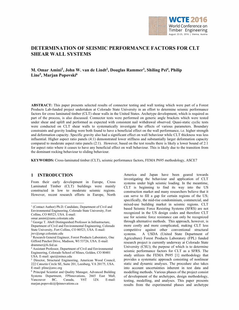
FEMA P695 is a methodology to evaluate seismic performance factors that include the response modification factor (R-factor), the system overstrength factor, and the deflection amplification factor for seismic design in the US. The methodology is an iterative process that consists of nonlinear static and dynamic analyses on a number of archetypes that are prototypical presentation of the seismic force resisting system. This iterative process is illustrated in Figure 1. These analyses result in computing margin against collapse of the archetype and hence the proposed system. It takes into account uncertainties inherent in the test data and modelling methods as well as variation in the ground motion records. The process is overseen by a technical peer panel and their involvement is critical throughout. It culminates in a project report along with the peer panel review that is then used in the code adoption process.
Figure 1: Overview of the FEMA P695 methodology 3 CLT TESTING
The FEMA P695 methodology requires testing at various levels to reliably capture behaviour of the proposed system. These tests include material testing,
components and connections, and assembly and system level tests. Material testing is not conducted as part of this project since material design strength is in accordance with the ANSI/APA PRG 320 [2] standard that provides information on performance and requirements for Rated Cross-Laminated Timber. 3.1 CONNECTOR TESTING
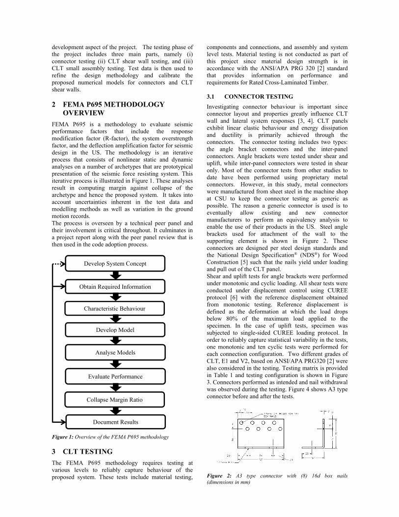
Investigating connector behaviour is important since connector layout and properties greatly influence CLT wall and lateral system responses [3, 4]. CLT panels exhibit linear elastic behaviour and energy dissipation and ductility is primarily achieved through the connectors. The connector testing includes two types: the angle bracket connectors and the inter-panel connectors. Angle brackets were tested under shear and uplift, while inter-panel connectors were tested in shear only. Most of the connector tests from other studies to date have been performed using proprietary metal connectors. However, in this study, metal connectors were manufactured from sheet steel in the machine shop at CSU to keep the connector testing as generic as possible. The reason a generic connector is used is to eventually allow existing and new connector manufacturers to perform an equivalency analysis to enable the use of their products in the US. Steel angle brackets used for attachment of the wall to the supporting element is shown in Figure 2. These connectors are designed per steel design standards and the National Design Specification® (NDS®) for Wood Construction [5] such that the nails yield under loading and pull out of the CLT panel. Shear and uplift tests for angle brackets were performed under monotonic and cyclic loading. All shear tests were conducted under displacement control using CUREE protocol [6] with the reference displacement obtained from monotonic testing. Reference displacement is defined as the deformation at which the load drops below 80% of the maximum load applied to the specimen. In the case of uplift tests, specimen was subjected to single-sided CUREE loading protocol. In order to reliably capture statistical variability in the tests, one monotonic and ten cyclic tests were performed for each connection configuration. Two different grades of CLT, E1 and V2, based on ANSI/APA PRG320 [2] were also considered in the testing. Testing matrix is provided in Table 1 and testing configuration is shown in Figure 3. Connectors performed as intended and nail withdrawal was observed during the testing. Figure 4 shows A3 type connector before and after the tests.
Figure 2: A3 type connector with (8) 16d box nails (dimensions in mm)
Develop System Concept
Obtain Required Information
Characteristic Behaviour
Develop Model
Analyse Models
Evaluate Performance
Collapse Margin Ratio
Document Results
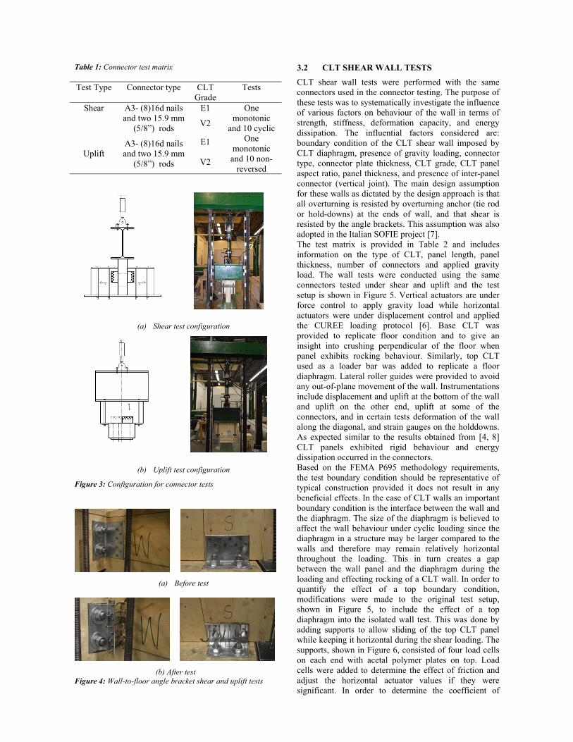
Table 1: Connector test matrix Test Type Connector type CLT
Grade Tests
Shear A3- (8)16d nails and two 15.9 mm
(5/8”) rods
E1 One monotonic
and 10 cyclic V2
Uplift A3- (8)16d nails and two 15.9 mm
(5/8”) rods
E1 One monotonic and 10 non-
reversed V2
(a) Shear test configuration
(b) Uplift test configuration
Figure 3: Configuration for connector tests
(a) Before test
(b) After test Figure 4: Wall-to-floor angle bracket shear and uplift tests
3.2 CLT SHEAR WALL TESTS
CLT shear wall tests were performed with the same connectors used in the connector testing. The purpose of these tests was to systematically investigate the influence of various factors on behaviour of the wall in terms of strength, stiffness, deformation capacity, and energy dissipation. The influential factors considered are: boundary condition of the CLT shear wall imposed by CLT diaphragm, presence of gravity loading, connector type, connector plate thickness, CLT grade, CLT panel aspect ratio, panel thickness, and presence of inter-panel connector (vertical joint). The main design assumption for these walls as dictated by the design approach is that all overturning is resisted by overturning anchor (tie rod or hold-downs) at the ends of wall, and that shear is resisted by the angle brackets. This assumption was also adopted in the Italian SOFIE project [7]. The test matrix is provided in Table 2 and includes information on the type of CLT, panel length, panel thickness, number of connectors and applied gravity load. The wall tests were conducted using the same connectors tested under shear and uplift and the test setup is shown in Figure 5. Vertical actuators are under force control to apply gravity load while horizontal actuators were under displacement control and applied the CUREE loading protocol [6]. Base CLT was provided to replicate floor condition and to give an insight into crushing perpendicular of the floor when panel exhibits rocking behaviour. Similarly, top CLT used as a loader bar was added to replicate a floor diaphragm. Lateral roller guides were provided to avoid any out-of-plane movement of the wall. Instrumentations include displacement and uplift at the bottom of the wall and uplift on the other end, uplift at some of the connectors, and in certain tests deformation of the wall along the diagonal, and strain gauges on the holddowns. As expected similar to the results obtained from [4, 8] CLT panels exhibited rigid behaviour and energy dissipation occurred in the connectors. Based on the FEMA P695 methodology requirements, the test boundary condition should be representative of typical construction provided it does not result in any beneficial effects. In the case of CLT walls an important boundary condition is the interface between the wall and the diaphragm. The size of the diaphragm is believed to affect the wall behaviour under cyclic loading since the diaphragm in a structure may be larger compared to the walls and therefore may remain relatively horizontal throughout the loading. This in turn creates a gap between the wall panel and the diaphragm during the loading and effecting rocking of a CLT wall. In order to quantify the effect of a top boundary condition, modifications were made to the original test setup, shown in Figure 5, to include the effect of a top diaphragm into the isolated wall test. This was done by adding supports to allow sliding of the top CLT panel while keeping it horizontal during the shear loading. The supports, shown in Figure 6, consisted of four load cells on each end with acetal polymer plates on top. Load cells were added to determine the effect of friction and adjust the horizontal actuator values if they were significant. In order to determine the coefficient of
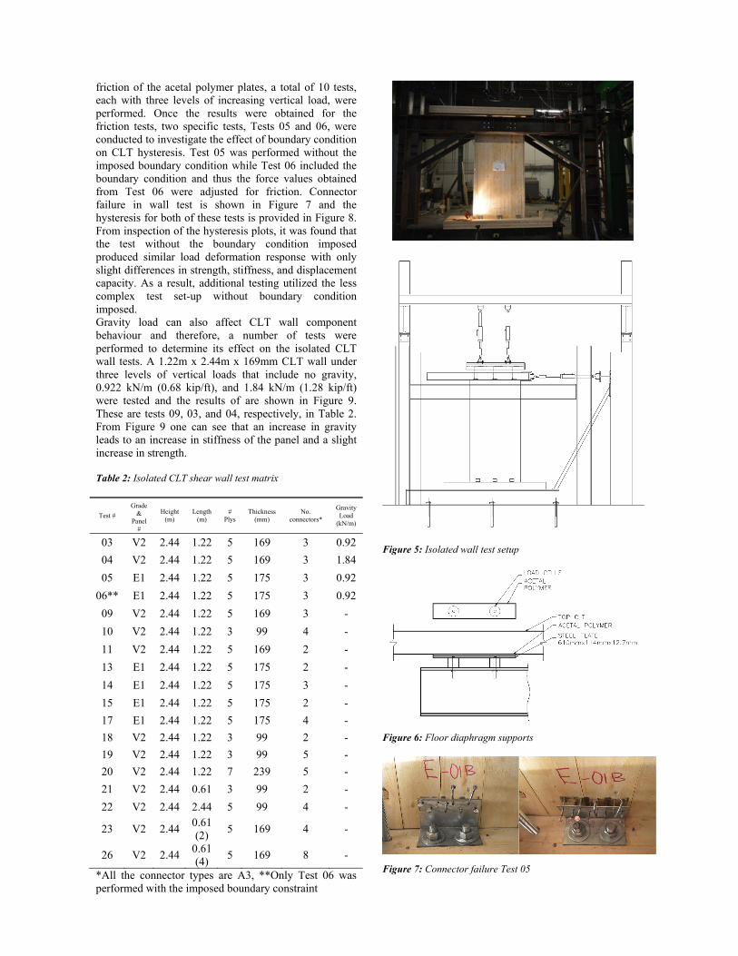
friction of the acetal polymer plates, a total of 10 tests, each with three levels of increasing vertical load, were performed. Once the results were obtained for the friction tests, two specific tests, Tests 05 and 06, were conducted to investigate the effect of boundary condition on CLT hysteresis. Test 05 was performed without the imposed boundary condition while Test 06 included the boundary condition and thus the force values obtained from Test 06 were adjusted for friction. Connector failure in wall test is shown in Figure 7 and the hysteresis for both of these tests is provided in Figure 8. From inspection of the hysteresis plots, it was found that the test without the boundary condition imposed produced similar load deformation response with only slight differences in strength, stiffness, and displacement capacity. As a result, additional testing utilized the less complex test set-up without boundary condition imposed. Gravity load can also affect CLT wall component behaviour and therefore, a number of tests were performed to determine its effect on the isolated CLT wall tests. A 1.22m x 2.44m x 169mm CLT wall under three levels of vertical loads that include no gravity, 0.922 kN/m (0.68 kip/ft), and 1.84 kN/m (1.28 kip/ft) were tested and the results of are shown in Figure 9. These are tests 09, 03, and 04, respectively, in Table 2. From Figure 9 one can see that an increase in gravity leads to an increase in stiffness of the panel and a slight increase in strength. Table 2: Isolated CLT shear wall test matrix
Test #
Grade &
Panel #
Height (m)
Length (m)
# Plys
Thickness (mm)
No. connectors*
Gravity Load
(kN/m)
03 V2 2.44 1.22 5 169 3 0.92
04 V2 2.44 1.22 5 169 3 1.84
05 E1 2.44 1.22 5 175 3 0.92
06** E1 2.44 1.22 5 175 3 0.92
09 V2 2.44 1.22 5 169 3 -
10 V2 2.44 1.22 3 99 4 -
11 V2 2.44 1.22 5 169 2 -
13 E1 2.44 1.22 5 175 2 -
14 E1 2.44 1.22 5 175 3 -
15 E1 2.44 1.22 5 175 2 -
17 E1 2.44 1.22 5 175 4 -
18 V2 2.44 1.22 3 99 2 -
19 V2 2.44 1.22 3 99 5 -
20 V2 2.44 1.22 7 239 5 -
21 V2 2.44 0.61 3 99 2 -
22 V2 2.44 2.44 5 99 4 -
23 V2 2.44 0.61 (2)
5 169 4 -
26 V2 2.44 0.61 (4)
5 169 8 -
*All the connector types are A3, **Only Test 06 was performed with the imposed boundary constraint
Figure 5: Isolated wall test setup
Figure 6: Floor diaphragm supports
Figure 7: Connector failure Test 05
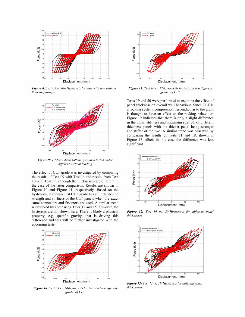
Figure 8: Test 05 vs. 06- Hysteresis for tests with and without floor diaphragms
Figure 9: 1.22mx2.44mx169mm specimen tested under different vertical loading
The effect of CLT grade was investigated by comparing the results of Test 09 with Test 14 and results from Test 10 with Test 17, although the thicknesses are different in the case of the latter comparison. Results are shown in Figure 10 and Figure 11, respectively. Based on the hysteresis, it appears that CLT grade has an influence on strength and stiffness of the CLT panels when the exact same connectors and fasteners are used. A similar trend is observed by comparing Tests 11 and 15; however, the hysteresis are not shown here. There is likely a physical property, e.g. specific gravity, that is driving this difference and this will be further investigated with the upcoming tests.
Figure 10: Test 09 vs. 14-Hysteresis for tests on two different grades of CLT
Figure 11: Test 10 vs. 17-Hysteresis for tests on two different grades of CLT
Tests 19 and 20 were performed to examine the effect of panel thickness on overall wall behaviour. Since CLT is a rocking system, compression perpendicular to the grain is thought to have an effect on the rocking behaviour. Figure 12 indicates that there is only a slight difference in the initial stiffness and maximum strength of different thickness panels with the thicker panel being stronger and stiffer of the two. A similar trend was observed by comparing the results of Tests 11 and 18, shown in Figure 13; albeit in this case the difference was less significant.
Figure 12: Test 19 vs. 20-Hysteresis for different panel thicknesses
Figure 13: Test 11 vs. 18-Hysteresis for different panel thicknesses
-200 -150 -100 -50 0 50 100 150 200-100
-80
-60
-40
-20
0
20
40
60
80
100
Displacement (mm)
For
ce (
kN)
Without BC
With BC
-100 -50 0 50 100
-60
-40
-20
0
20
40
60
Displacement (mm)
For
ce (
kN)
No gravity
0.92 kN/m gravity1.84 kN/m gravity
-150 -100 -50 0 50 100 150-100
-80
-60
-40
-20
0
20
40
60
80
100
Displacement (mm)
For
ce (
kN)
V2 grade
E1 grade
-150 -100 -50 0 50 100 150
-100
-50
0
50
100
Displacement (mm)
For
ce (
kN)
V2 grade
E1 grade
-100 -50 0 50 100-100
-80
-60
-40
-20
0
20
40
60
80
100
Displacement (mm)
For
ce (
kN)
t=99 mm (3.9")
t=239 mm (9.41")
-100 -50 0 50 100-40
-30
-20
-10
0
10
20
30
40
Displacement (mm)
For
ce (
kN)
t=99 mm (3.9")
t=168.9 mm (6.65")
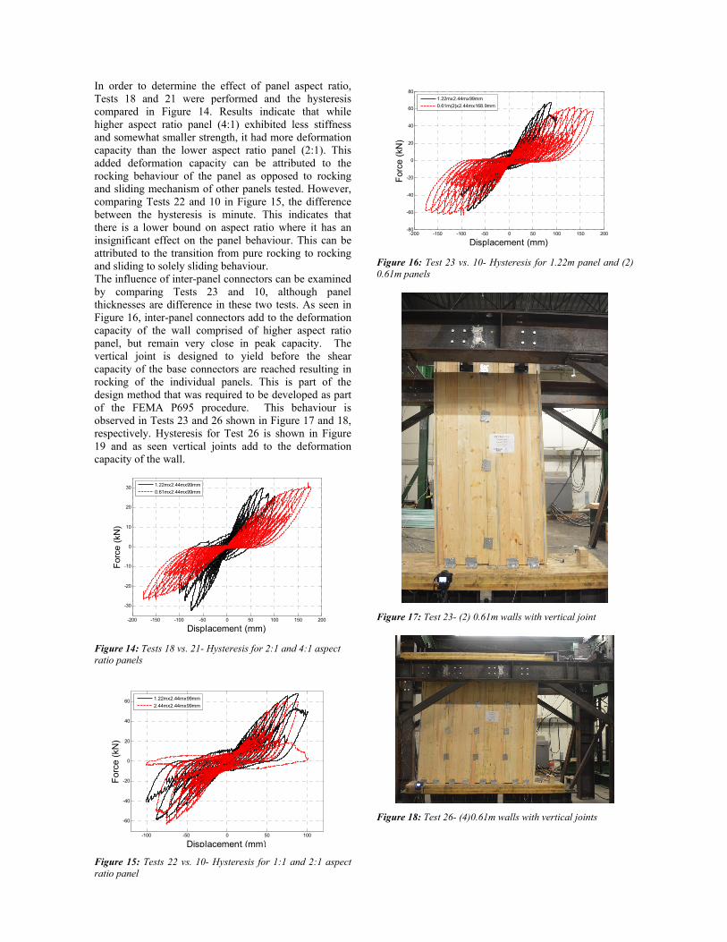
In order to determine the effect of panel aspect ratio, Tests 18 and 21 were performed and the hysteresis compared in Figure 14. Results indicate that while higher aspect ratio panel (4:1) exhibited less stiffness and somewhat smaller strength, it had more deformation capacity than the lower aspect ratio panel (2:1). This added deformation capacity can be attributed to the rocking behaviour of the panel as opposed to rocking and sliding mechanism of other panels tested. However, comparing Tests 22 and 10 in Figure 15, the difference between the hysteresis is minute. This indicates that there is a lower bound on aspect ratio where it has an insignificant effect on the panel behaviour. This can be attributed to the transition from pure rocking to rocking and sliding to solely sliding behaviour. The influence of inter-panel connectors can be examined by comparing Tests 23 and 10, although panel thicknesses are difference in these two tests. As seen in Figure 16, inter-panel connectors add to the deformation capacity of the wall comprised of higher aspect ratio panel, but remain very close in peak capacity. The vertical joint is designed to yield before the shear capacity of the base connectors are reached resulting in rocking of the individual panels. This is part of the design method that was required to be developed as part of the FEMA P695 procedure. This behaviour is observed in Tests 23 and 26 shown in Figure 17 and 18, respectively. Hysteresis for Test 26 is shown in Figure 19 and as seen vertical joints add to the deformation capacity of the wall.
Figure 14: Tests 18 vs. 21- Hysteresis for 2:1 and 4:1 aspect ratio panels
Figure 15: Tests 22 vs. 10- Hysteresis for 1:1 and 2:1 aspect ratio panel
Figure 16: Test 23 vs. 10- Hysteresis for 1.22m panel and (2) 0.61m panels
Figure 17: Test 23- (2) 0.61m walls with vertical joint
Figure 18: Test 26- (4)0.61m walls with vertical joints
-200 -150 -100 -50 0 50 100 150 200
-30
-20
-10
0
10
20
30
Displacement (mm)
For
ce (
kN)
1.22mx2.44mx99mm
0.61mx2.44mx99mm
-100 -50 0 50 100
-60
-40
-20
0
20
40
60
Displacement (mm)
For
ce (
kN)
1.22mx2.44mx99mm
2.44mx2.44mx99mm
-200 -150 -100 -50 0 50 100 150 200-80
-60
-40
-20
0
20
40
60
80
Displacement (mm)
For
ce (
kN)
1.22mx2.44mx99mm
0.61m(2)x2.44mx168.9mm
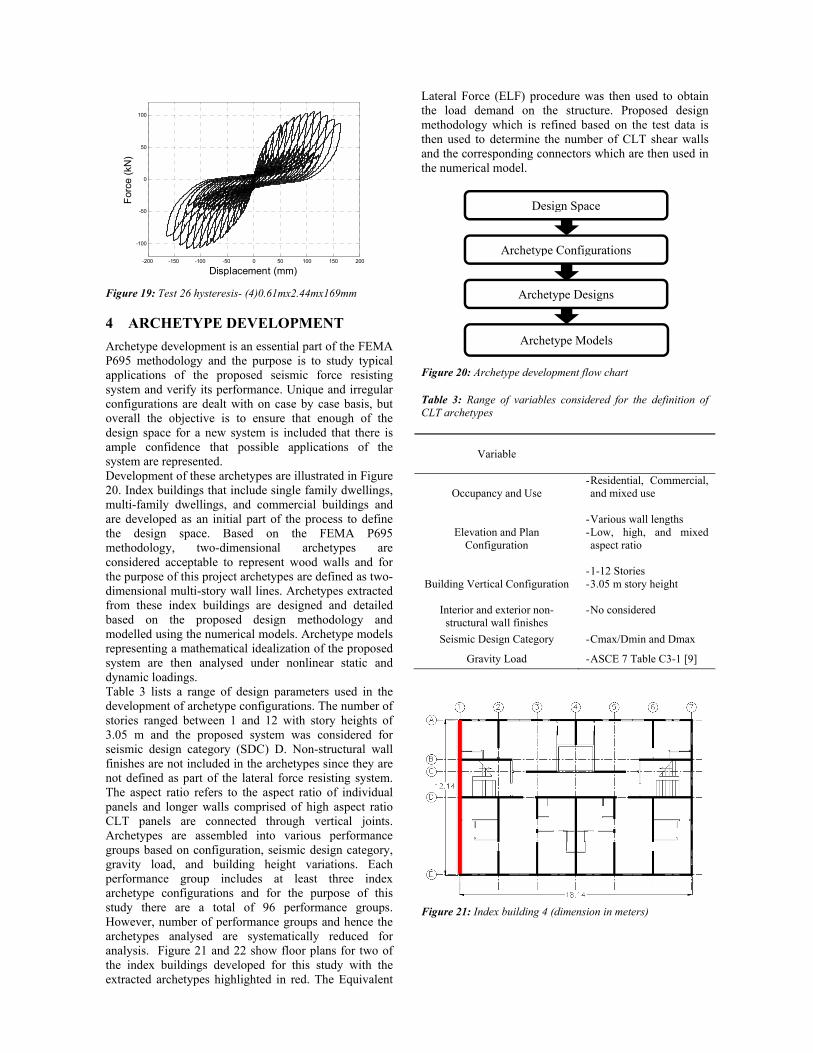
Figure 19: Test 26 hysteresis- (4)0.61mx2.44mx169mm
4 ARCHETYPE DEVELOPMENT
Archetype development is an essential part of the FEMA P695 methodology and the purpose is to study typical applications of the proposed seismic force resisting system and verify its performance. Unique and irregular configurations are dealt with on case by case basis, but overall the objective is to ensure that enough of the design space for a new system is included that there is ample confidence that possible applications of the system are represented. Development of these archetypes are illustrated in Figure 20. Index buildings that include single family dwellings, multi-family dwellings, and commercial buildings and are developed as an initial part of the process to define the design space. Based on the FEMA P695 methodology, two-dimensional archetypes are considered acceptable to represent wood walls and for the purpose of this project archetypes are defined as two-dimensional multi-story wall lines. Archetypes extracted from these index buildings are designed and detailed based on the proposed design methodology and modelled using the numerical models. Archetype models representing a mathematical idealization of the proposed system are then analysed under nonlinear static and dynamic loadings. Table 3 lists a range of design parameters used in the development of archetype configurations. The number of stories ranged between 1 and 12 with story heights of 3.05 m and the proposed system was considered for seismic design category (SDC) D. Non-structural wall finishes are not included in the archetypes since they are not defined as part of the lateral force resisting system. The aspect ratio refers to the aspect ratio of individual panels and longer walls comprised of high aspect ratio CLT panels are connected through vertical joints. Archetypes are assembled into various performance groups based on configuration, seismic design category, gravity load, and building height variations. Each performance group includes at least three index archetype configurations and for the purpose of this study there are a total of 96 performance groups. However, number of performance groups and hence the archetypes analysed are systematically reduced for analysis. Figure 21 and 22 show floor plans for two of the index buildings developed for this study with the extracted archetypes highlighted in red. The Equivalent
Lateral Force (ELF) procedure was then used to obtain the load demand on the structure. Proposed design methodology which is refined based on the test data is then used to determine the number of CLT shear walls and the corresponding connectors which are then used in the numerical model.
Figure 20: Archetype development flow chart Table 3: Range of variables considered for the definition of CLT archetypes
Variable
Occupancy and Use - Residential, Commercial, and mixed use
Elevation and Plan Configuration
- Various wall lengths - Low, high, and mixed aspect ratio
Building Vertical Configuration - 1-12 Stories - 3.05 m story height
Interior and exterior non-structural wall finishes
- No considered
Seismic Design Category - Cmax/Dmin and Dmax
Gravity Load - ASCE 7 Table C3-1 [9]
Figure 21: Index building 4 (dimension in meters)
-200 -150 -100 -50 0 50 100 150 200
-100
-50
0
50
100
Displacement (mm)
For
ce (
kN)
Design Space
Archetype Configurations
Archetype Designs
Archetype Models
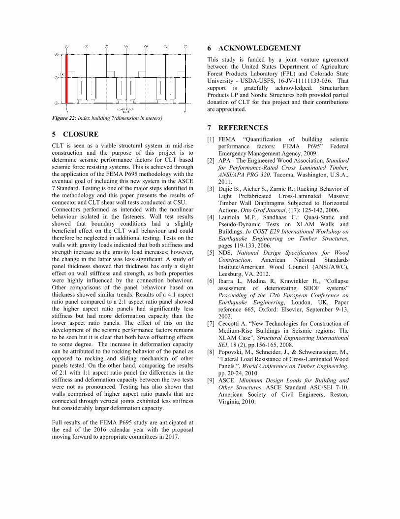
Figure 22: Index building 7(dimension in meters)
5 CLOSURE
CLT is seen as a viable structural system in mid-rise construction and the purpose of this project is to determine seismic performance factors for CLT based seismic force resisting systems. This is achieved through the application of the FEMA P695 methodology with the eventual goal of including this new system in the ASCE 7 Standard. Testing is one of the major steps identified in the methodology and this paper presents the results of connector and CLT shear wall tests conducted at CSU. Connectors performed as intended with the nonlinear behaviour isolated in the fasteners. Wall test results showed that boundary conditions had a slightly beneficial effect on the CLT wall behaviour and could therefore be neglected in additional testing. Tests on the walls with gravity loads indicated that both stiffness and strength increase as the gravity load increases; however, the change in the latter was less significant. A study of panel thickness showed that thickness has only a slight effect on wall stiffness and strength, as both properties were highly influenced by the connection behaviour. Other comparisons of the panel behaviour based on thickness showed similar trends. Results of a 4:1 aspect ratio panel compared to a 2:1 aspect ratio panel showed the higher aspect ratio panels had significantly less stiffness but had more deformation capacity than the lower aspect ratio panels. The effect of this on the development of the seismic performance factors remains to be seen but it is clear that both have offsetting effects to some degree. The increase in deformation capacity can be attributed to the rocking behavior of the panel as opposed to rocking and sliding mechanism of other panels tested. On the other hand, comparing the results of 2:1 with 1:1 aspect ratio panel the differences in the stiffness and deformation capacity between the two tests were not as pronounced. Testing has also shown that walls comprised of higher aspect ratio panels that are connected through vertical joints exhibited less stiffness but considerably larger deformation capacity.
Full results of the FEMA P695 study are anticipated at the end of the 2016 calendar year with the proposal moving forward to appropriate committees in 2017.
6 ACKNOWLEDGEMENT
This study is funded by a joint venture agreement between the United States Department of Agriculture Forest Products Laboratory (FPL) and Colorado State University - USDA-USFS, 16-JV-11111133-036. That support is gratefully acknowledged. Structurlam Products LP and Nordic Structures both provided partial donation of CLT for this project and their contributions are appreciated.
7 REFERENCES
[1] FEMA “Quantification of building seismic performance factors: FEMA P695” Federal Emergency Management Agency, 2009.
[2] APA - The Engineered Wood Association, Standard for Performance-Rated Cross Laminated Timber, ANSI/APA PRG 320. Tacoma, Washington, U.S.A., 2011.
[3] Dujic B., Aicher S., Zarnic R.: Racking Behavior of Light Prefabricated Cross-Laminated Massive Timber Wall Diaphragms Subjected to Horizontal Actions. Otto Graf Journal, (17): 125-142, 2006.
[4] Lauriola M.P., Sandhaas C.: Quasi-Static and Pseudo-Dynamic Tests on XLAM Walls and Buildings. In COST E29 International Workshop on Earthquake Engineering on Timber Structures, pages 119-133, 2006.
[5] NDS, National Design Specification for Wood Construction. American National Standards Institute/American Wood Council (ANSI/AWC), Leesburg, VA, 2012.
[6] Ibarra L, Medina R, Krawinkler H., “Collapse assessment of deteriorating SDOF systems” Proceeding of the 12th European Conference on Earthquake Engineering, London, UK, Paper reference 665, Oxford: Elsevier, September 9-13, 2002.
[7] Ceccotti A. “New Technologies for Construction of Medium-Rise Buildings in Seismic regions: The XLAM Case”, Structural Engineering International SEI, 18 (2), pp.156-165, 2008.
[8] Popovski, M., Schneider, J., & Schweinsteiger, M., “Lateral Load Resistance of Cross-Laminated Wood Panels.”, World Conference on Timber Engineering, pp. 20-24, 2010.
[9] ASCE. Minimum Design Loads for Building and Other Structures. ASCE Standard ASC/SEI 7-10, American Society of Civil Engineers, Reston, Virginia, 2010.