Embed Size (px)
Citation preview
Developing a Methodology for Certifying Heavy Duty Hybrids based on HILS 1
21 March 2012
Institute for Internal Combustion Engines and Thermodynamics
Developing a Methodology for Certifying Heavy Duty Hybrids based on HILS
9th MEETING OF THE GRPE INFORMAL GROUP ON
HEAVY DUTY HYBRIDS (HDH)
21.-23. March 2012
TU GrazInstitute for Internal Combustion Engines and Thermodynamics
Stefan Hausberger, Gérard Silberholz
Working Paper No. HDH-09-06(9th HDH meeting, 21 to 23 March 2012)
Developing a Methodology for Certifying Heavy Duty Hybrids based on HILS 2
21 March 2012
Institute for Internal Combustion Engines and Thermodynamics
1. Introduction = conclusions from last meetings2. Test cycle for HDH, review of discussed methods
2.1 Overview vehicle cycle and wheel hub cycle (WHDHC)2.2 Comparison of resulting power pack load cycles2.3 For WHDHC: Normalisation of negative (braking) power2.4 Validation of wheel hub cycle WHDHC2.5 Harmonisation of methods for conventional engine testing,
HDV CO2 test procedures and HILS using the WHDHC2.6 Open issues
3. WHVC weighting factors 4. Inclusion of PTO operation5. Summary 6. Suggestion for next steps
Content
Developing a Methodology for Certifying Heavy Duty Hybrids based on HILS 3
21 March 2012
Institute for Internal Combustion Engines and Thermodynamics
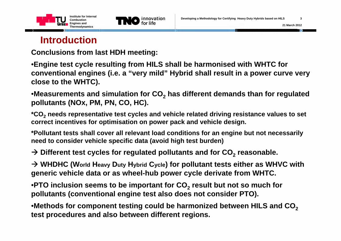
IntroductionConclusions from last HDH meeting:•Engine test cycle resulting from HILS shall be harmonised with WHTC for conventional engines (i.e. a “very mild” Hybrid shall result in a power curve very close to the WHTC).•Measurements and simulation for CO2 has different demands than for regulated pollutants (NOx, PM, PN, CO, HC). *CO2 needs representative test cycles and vehicle related driving resistance values to set correct incentives for optimisation on power pack and vehicle design. *Pollutant tests shall cover all relevant load conditions for an engine but not necessarily need to consider vehicle specific data (avoid high test burden)
Different test cycles for regulated pollutants and for CO2 reasonable.WHDHC (World Heavy Duty Hybrid Cycle) for pollutant tests either as WHVC with generic vehicle data or as wheel-hub power cycle derivate from WHTC.•PTO inclusion seems to be important for CO2 result but not so much for pollutants (conventional engine test also does not consider PTO).•Methods for component testing could be harmonized between HILS and CO2test procedures and also between different regions.
Developing a Methodology for Certifying Heavy Duty Hybrids based on HILS 4
21 March 2012
Institute for Internal Combustion Engines and Thermodynamics
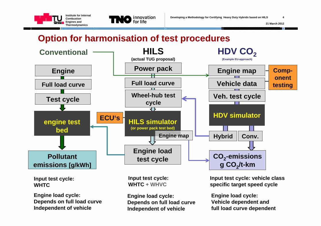
Option for harmonisation of test proceduresHILS
(actual TUG proposal)
Power pack
Wheel-hub test cycle
Engine load test cycle
HDV CO2(Example EU-approach)
Vehicle data
Veh. test cycle
CO2-emissionsg CO2/t-km
Engine map
a
HDV simulatora
HILS simulator(or power pack test bed)
Conventional
Engine
Test cycle
Pollutant emissions [g/kWh]
a
engine test bed
Engine load cycle:Depends on full load curveIndependent of vehicle
Engine load cycle:Vehicle dependent and full load curve dependent
Full load curve Full load curve
Engine load cycle:Depends on full load curveIndependent of vehicle
Input test cycle:WHTC
Input test cycle:WHTC + WHVC
Input test cycle: vehicle class specific target speed cycle
Comp-onent
testing
ECU‘s
Hybrid Engine map Conv.
Developing a Methodology for Certifying Heavy Duty Hybrids based on HILS 5
21 March 2012
Institute for Internal Combustion Engines and Thermodynamics
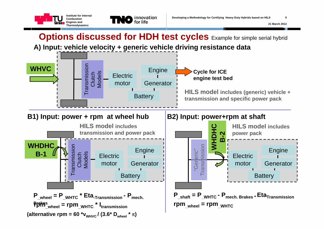
Options discussed for HDH test cycles Example for simple serial hybrid
Electric motor Generator
Engine
Tran
smis
sion
Clu
tch
Mod
els
Battery
A) Input: vehicle velocity + generic vehicle driving resistance data
WHVC Cycle for ICE engine test bed
B1) Input: power + rpm at wheel hub
Electric motor Generator
Engine
Tran
smis
sion
Clu
tch
Mod
els
Battery
WHDHCB-1
HILS model includes (generic) vehicle + transmission and specific power pack
Electric motor Generator
Engine
“Gen
eric
”Tr
ansm
issi
on
Battery
WH
DH
CB
-2
HILS model includes transmission and power pack
HILS model includes power pack
P_wheel = P_WHTC * Eta-Transmission - Pmech. Brakesrpm_wheel = rpm_WHTC * Itransmission
(alternative rpm = 60 *vWHVC / (3.6* Dwheel * )
B2) Input: power+rpm at shaft
P_shaft = P_WHTC - Pmech. Brakes * EtaTransmission
rpm_wheel = rpm_WHTC
Developing a Methodology for Certifying Heavy Duty Hybrids based on HILS 6
21 March 2012
Institute for Internal Combustion Engines and Thermodynamics
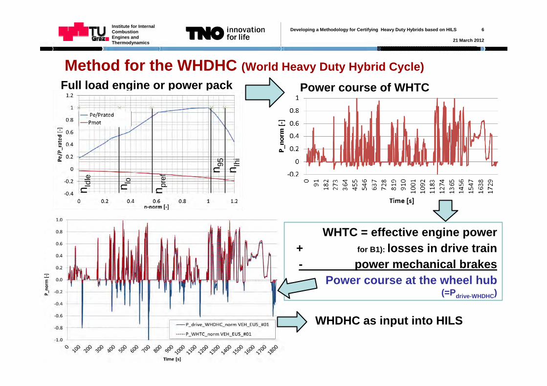
Method for the WHDHC (World Heavy Duty Hybrid Cycle)Full load engine or power pack
n Idl
e
n lo
n pre
f n 95
n Ihi
Power course of WHTC
WHTC = effective engine power+ for B1): losses in drive train- power mechanical brakes
Power course at the wheel hub(=Pdrive-WHDHC)
WHDHC as input into HILS
Developing a Methodology for Certifying Heavy Duty Hybrids based on HILS 7
21 March 2012
Institute for Internal Combustion Engines and Thermodynamics
Method for the WHDHC – Normalizing negative power
Related questions: 1) Does the drivers deceleration behaviour depend on shape of full load curve? Analysis of measured real world driving cycles for several buses on same route in city of Vienna with different engines. Is average negative power higher for engines with higher torque at low engine speeds? Yesa), Nob)
Main question:How can negative power (mechanical brakes + engine) be normalised to be representative for all vehicle categories?Options:a) Normalise as % of motoring curve at given engine speed
(similar to positive engine power in WHTC)b) Normalise as % of rated engine powerc) Add further parameters to a) or b)
2) Is the average negative power different for different vehicle categories?Analysis of different vehicles in WHVC (delivery truck, bus, tractor-trailer,..): is normalised negative power significantly different between HDV categories?
Yes find further parameter for normalisationNo use a) or b) from above directly
Developing a Methodology for Certifying Heavy Duty Hybrids based on HILS 8
21 March 2012
Institute for Internal Combustion Engines and Thermodynamics
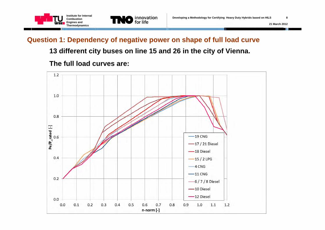
Question 1: Dependency of negative power on shape of full load curve13 different city buses on line 15 and 26 in the city of Vienna.
The full load curves are:
Developing a Methodology for Certifying Heavy Duty Hybrids based on HILS 9
21 March 2012
Institute for Internal Combustion Engines and Thermodynamics
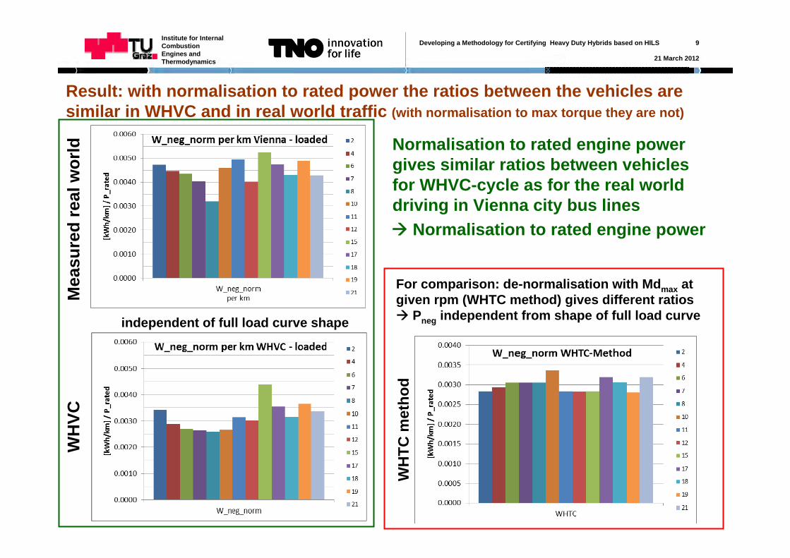
Result: with normalisation to rated power the ratios between the vehicles are similar in WHVC and in real world traffic (with normalisation to max torque they are not)
WH
VC
WH
TC m
etho
d
For comparison: de-normalisation with Mdmax at given rpm (WHTC method) gives different ratios Pneg independent from shape of full load curveindependent of full load curve shape
Normalisation to rated engine power
Normalisation to rated engine power gives similar ratios between vehicles for WHVC-cycle as for the real world driving in Vienna city bus lines
Mea
sure
d re
al w
orld
Developing a Methodology for Certifying Heavy Duty Hybrids based on HILS 10
21 March 2012
Institute for Internal Combustion Engines and Thermodynamics
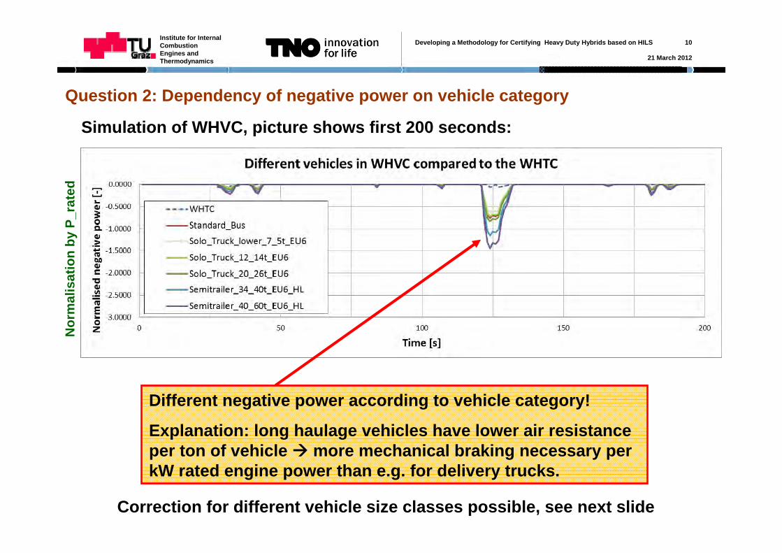
Question 2: Dependency of negative power on vehicle category
Simulation of WHVC, picture shows first 200 seconds:
Nor
mal
isat
ion
by P
_rat
ed
Different negative power according to vehicle category!
Explanation: long haulage vehicles have lower air resistance per ton of vehicle more mechanical braking necessary per kW rated engine power than e.g. for delivery trucks.
Correction for different vehicle size classes possible, see next slide
Developing a Methodology for Certifying Heavy Duty Hybrids based on HILS 11
21 March 2012
Institute for Internal Combustion Engines and Thermodynamics
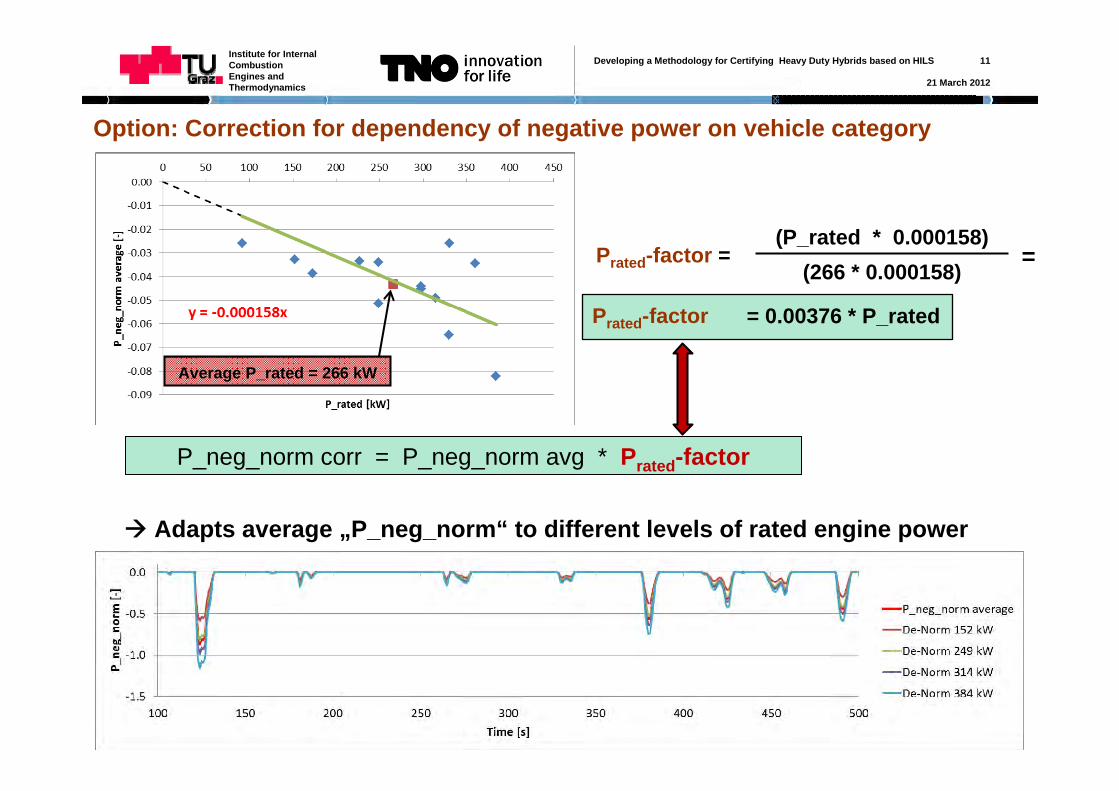
Option: Correction for dependency of negative power on vehicle category
Prated-factor =(P_rated * 0.000158)
(266 * 0.000158)
Average P_rated = 266 kW
Adapts average „P_neg_norm“ to different levels of rated engine power
P_neg_norm corr = P_neg_norm avg * Prated-factor
= 0.00376 * P_ratedPrated-factor
=
Developing a Methodology for Certifying Heavy Duty Hybrids based on HILS 12
21 March 2012
Institute for Internal Combustion Engines and Thermodynamics
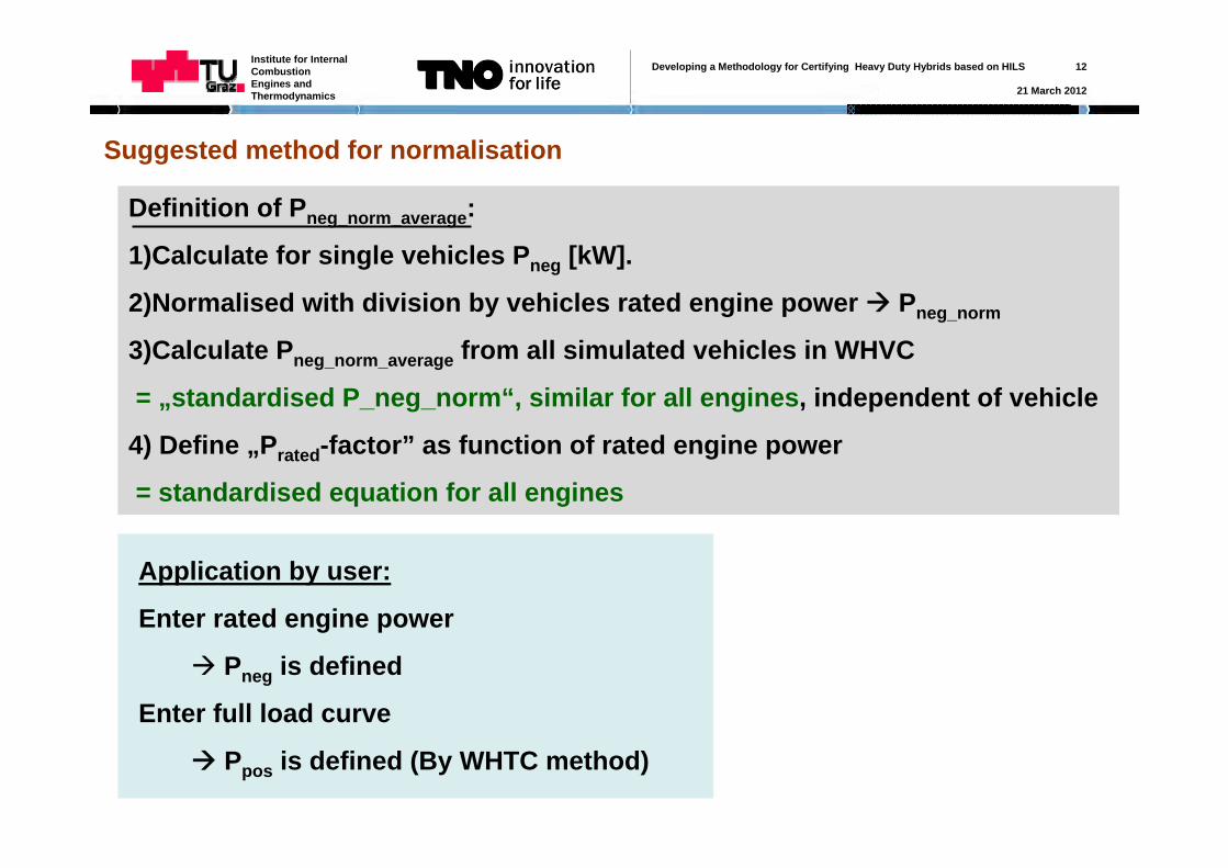
Suggested method for normalisation
Application by user:
Enter rated engine power
Pneg is defined
Enter full load curve
Ppos is defined (By WHTC method)
Definition of Pneg_norm_average:
1)Calculate for single vehicles Pneg [kW].
2)Normalised with division by vehicles rated engine power Pneg_norm
3)Calculate Pneg_norm_average from all simulated vehicles in WHVC
= „standardised P_neg_norm“, similar for all engines, independent of vehicle
4) Define „Prated-factor” as function of rated engine power
= standardised equation for all engines
Developing a Methodology for Certifying Heavy Duty Hybrids based on HILS 13
21 March 2012
Institute for Internal Combustion Engines and Thermodynamics
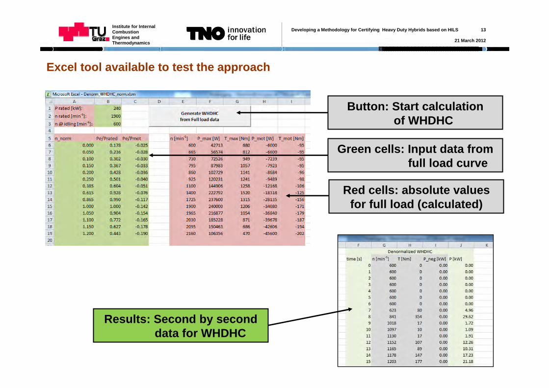
Excel tool available to test the approach
Green cells: Input data fromfull load curve
Button: Start calculation of WHDHC
Results: Second by seconddata for WHDHC
Red cells: absolute values for full load (calculated)
Developing a Methodology for Certifying Heavy Duty Hybrids based on HILS 14
21 March 2012
Institute for Internal Combustion Engines and Thermodynamics
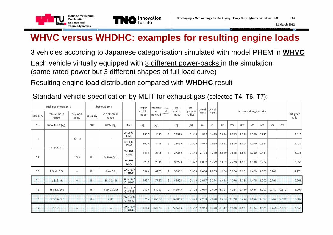
WHVC versus WHDHC: examples for resulting engine loads3 vehicles according to Japanese categorisation simulated with model PHEM in WHVCEach vehicle virtually equipped with 3 different power-packs in the simulation (same rated power but 3 different shapes of full load curve)Resulting engine load distribution compared with WHDHC result
categoryvehicle mass
rangepay load
rangecategory
vehicle mass range
NO G V W /G C W (kg) NO G V W (kg) fuel (kg) (kg) (kg) (m) (m) (m) 1st 2nd 3rd 4th 5th 6th 7th
D・LPG・CNG
1957 1490 3 2757.0 0.313 1.982 1.695 5.076 2.713 1.529 1.000 0.795 4.615
G・LPG・CNG
1659 1458 3 2443.0 0.303 1.975 1.695 4.942 2.908 1.568 1.000 0.834 4.477
D・LPG・CNG
2482 2396 3 3735.0 0.343 2.106 1.780 5.080 2.816 1.587 1.000 0.741 5.275
G・LPG・CNG
2259 2016 3 3322.0 0.327 2.052 1.722 5.089 2.773 1.577 1.000 0.777 6.051
T3 7.5t<&≦8t - B 2 6t<&≦8t G・D・LPG・CNG
3543 4275 2 5735.5 0.388 2.454 2.235 6.350 3.876 2.301 1.423 1.000 0.762 4.771
T4 8t<&≦16t - B 3 8t<&≦16t G・D・LPG・CNG
4527 7737 2 8450.5 0.469 2.617 2.374 6.416 4.096 2.385 1.475 1.000 0.760 5.208
T5 16t<&≦20t - B 4 16t<&≦20t G・D・LPG・CNG
8688 11089 2 14287.5 0.502 3.049 2.490 6.331 4.224 2.410 1.486 1.000 0.763 0.612 6.309
T6 20t<&≦25t - B 5 20t< G・D・LPG・CNG
8765 15530 2 16585.0 0.473 2.934 2.490 6.304 4.170 2.393 1.456 1.000 0.752 0.604 5.102
T7 25t< - - -G・D・LPG・CNG
12120 24974 2 24662.0 0.507 2.961 2.490 6.147 4.000 2.281 1.434 1.000 0.760 0.597 6.061
transmission gear ratiotest
vehicle mass
-
bus category
-
empty vehicle mass
maximum
payload
number of
persons
tire dynamic
radius
overall hight
overall width
3.5t<&≦6tT2 1.5t<
3.5t<&≦7.5t
B 1
diff gear ratio
T1 ≦1.5t
truck/tructor category
Standard vehicle specification by MLIT for exhaust gas (selected T4, T6, T7):
Developing a Methodology for Certifying Heavy Duty Hybrids based on HILS 15
21 March 2012
Institute for Internal Combustion Engines and Thermodynamics
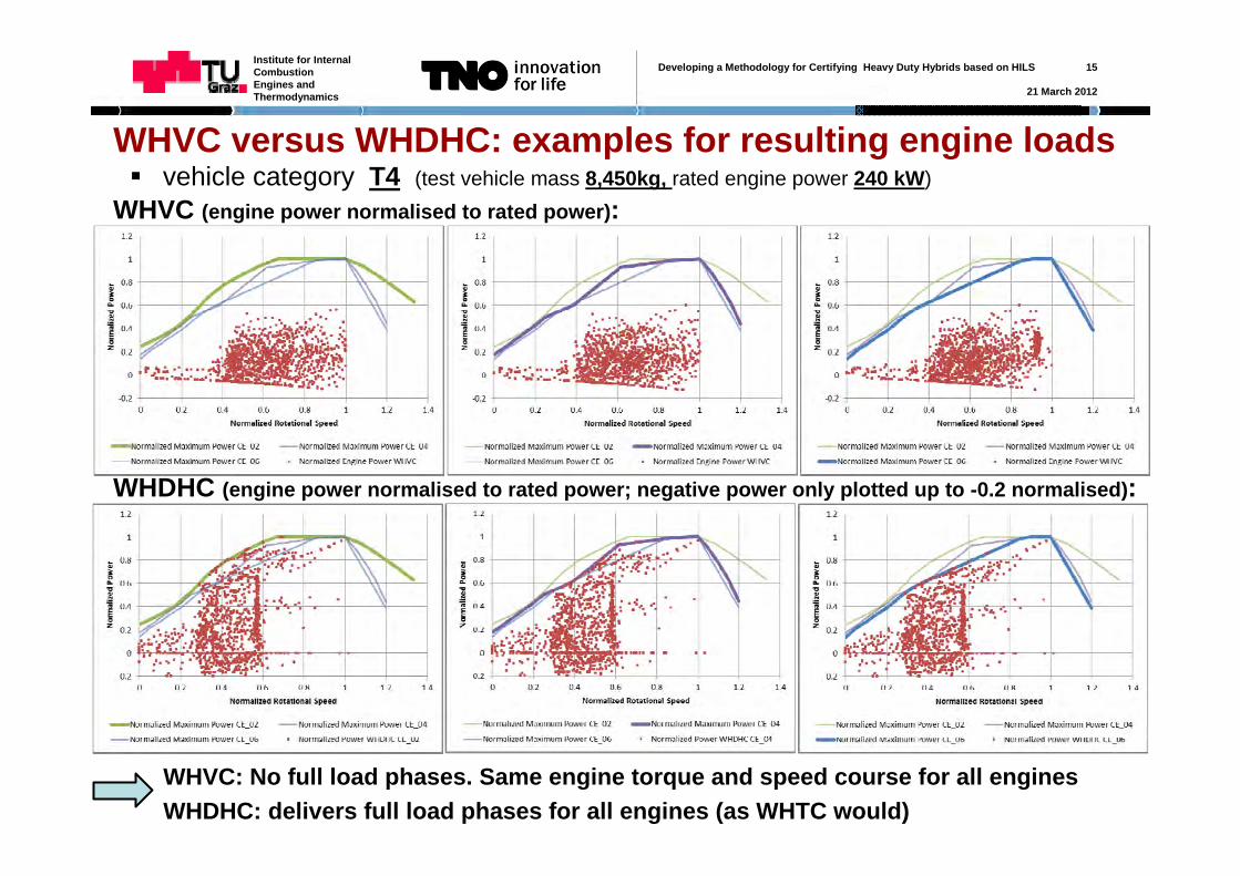
vehicle category T4 (test vehicle mass 8,450kg, rated engine power 240 kW)
WHVC: No full load phases. Same engine torque and speed course for all enginesWHDHC: delivers full load phases for all engines (as WHTC would)
WHVC versus WHDHC: examples for resulting engine loads
WHVC (engine power normalised to rated power):
WHDHC (engine power normalised to rated power; negative power only plotted up to -0.2 normalised):
Developing a Methodology for Certifying Heavy Duty Hybrids based on HILS 16
21 March 2012
Institute for Internal Combustion Engines and Thermodynamics
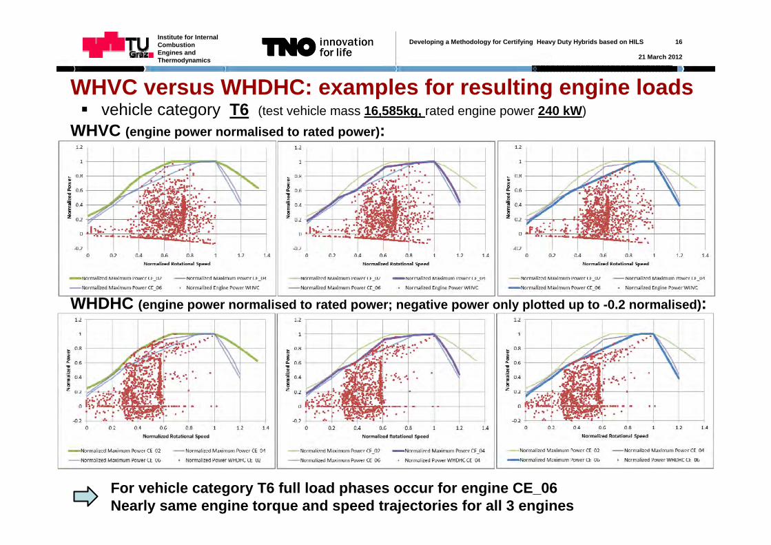
vehicle category T6 (test vehicle mass 16,585kg, rated engine power 240 kW)
For vehicle category T6 full load phases occur for engine CE_06Nearly same engine torque and speed trajectories for all 3 engines
WHVC versus WHDHC: examples for resulting engine loads
WHVC (engine power normalised to rated power):
WHDHC (engine power normalised to rated power; negative power only plotted up to -0.2 normalised):
Developing a Methodology for Certifying Heavy Duty Hybrids based on HILS 17
21 March 2012
Institute for Internal Combustion Engines and Thermodynamics
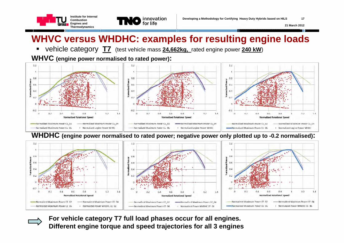
vehicle category T7 (test vehicle mass 24,662kg, rated engine power 240 kW)
For vehicle category T7 full load phases occur for all engines.Different engine torque and speed trajectories for all 3 engines
WHVC versus WHDHC: examples for resulting engine loads
WHVC (engine power normalised to rated power):
WHDHC (engine power normalised to rated power; negative power only plotted up to -0.2 normalised):
Developing a Methodology for Certifying Heavy Duty Hybrids based on HILS 18
21 March 2012
Institute for Internal Combustion Engines and Thermodynamics
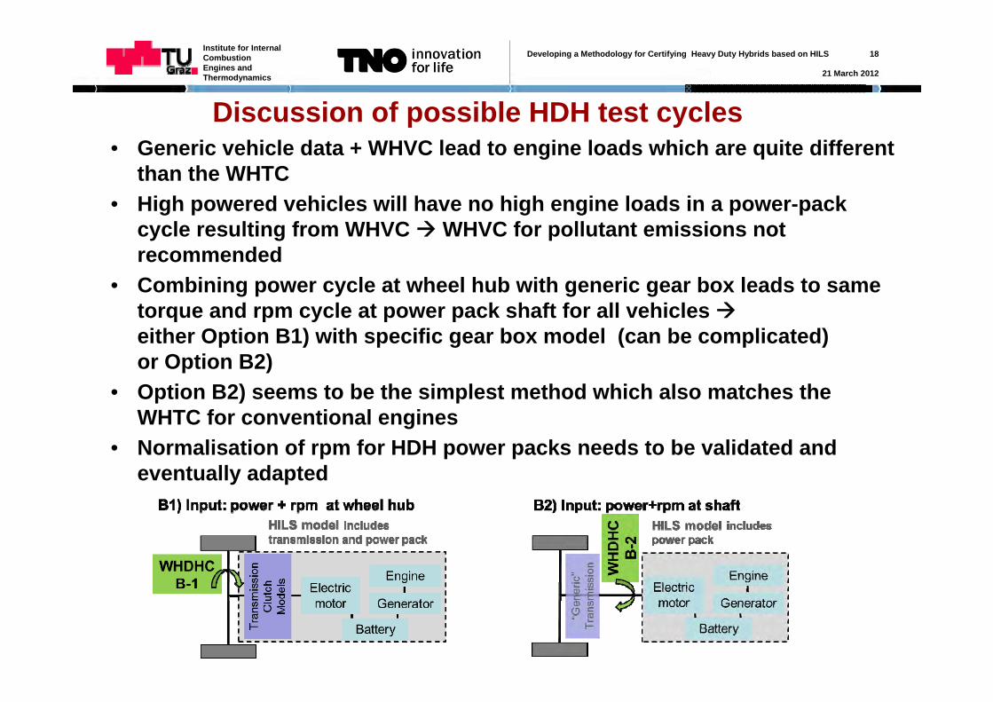
Discussion of possible HDH test cycles• Generic vehicle data + WHVC lead to engine loads which are quite different
than the WHTC• High powered vehicles will have no high engine loads in a power-pack
cycle resulting from WHVC WHVC for pollutant emissions not recommended
• Combining power cycle at wheel hub with generic gear box leads to same torque and rpm cycle at power pack shaft for all vehicles either Option B1) with specific gear box model (can be complicated)or Option B2)
• Option B2) seems to be the simplest method which also matches the WHTC for conventional engines
• Normalisation of rpm for HDH power packs needs to be validated and eventually adapted
Developing a Methodology for Certifying Heavy Duty Hybrids based on HILS 19
21 March 2012
Institute for Internal Combustion Engines and Thermodynamics
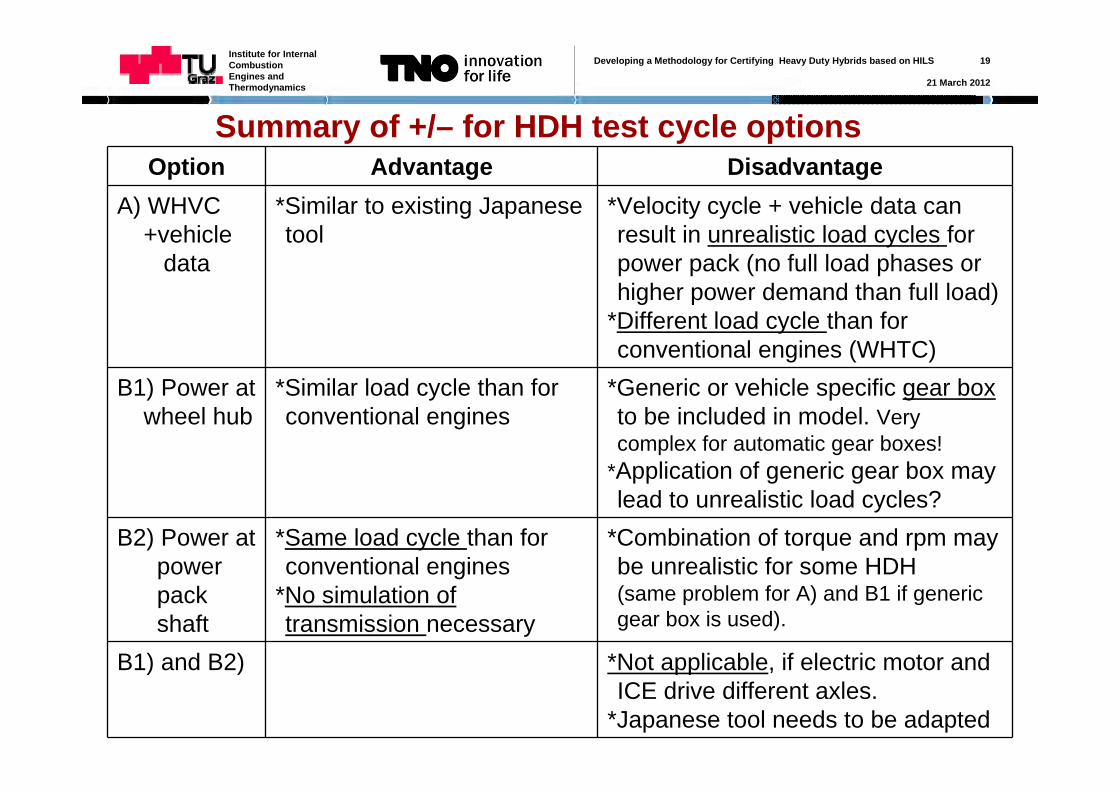
Summary of +/– for HDH test cycle optionsOption Advantage Disadvantage
A) WHVC +vehicle
data
*Similar to existing Japanese tool
*Velocity cycle + vehicle data can result in unrealistic load cycles for power pack (no full load phases or higher power demand than full load)
*Different load cycle than for conventional engines (WHTC)
B1) Power at wheel hub
*Similar load cycle than for conventional engines
*Generic or vehicle specific gear box to be included in model. Very complex for automatic gear boxes!
*Application of generic gear box may lead to unrealistic load cycles?
B2) Power at power pack shaft
*Same load cycle than for conventional engines
*No simulation of transmission necessary
*Combination of torque and rpm may be unrealistic for some HDH(same problem for A) and B1 if generic gear box is used).
B1) and B2) *Not applicable, if electric motor and ICE drive different axles.
*Japanese tool needs to be adapted
Developing a Methodology for Certifying Heavy Duty Hybrids based on HILS 20
21 March 2012
Institute for Internal Combustion Engines and Thermodynamics
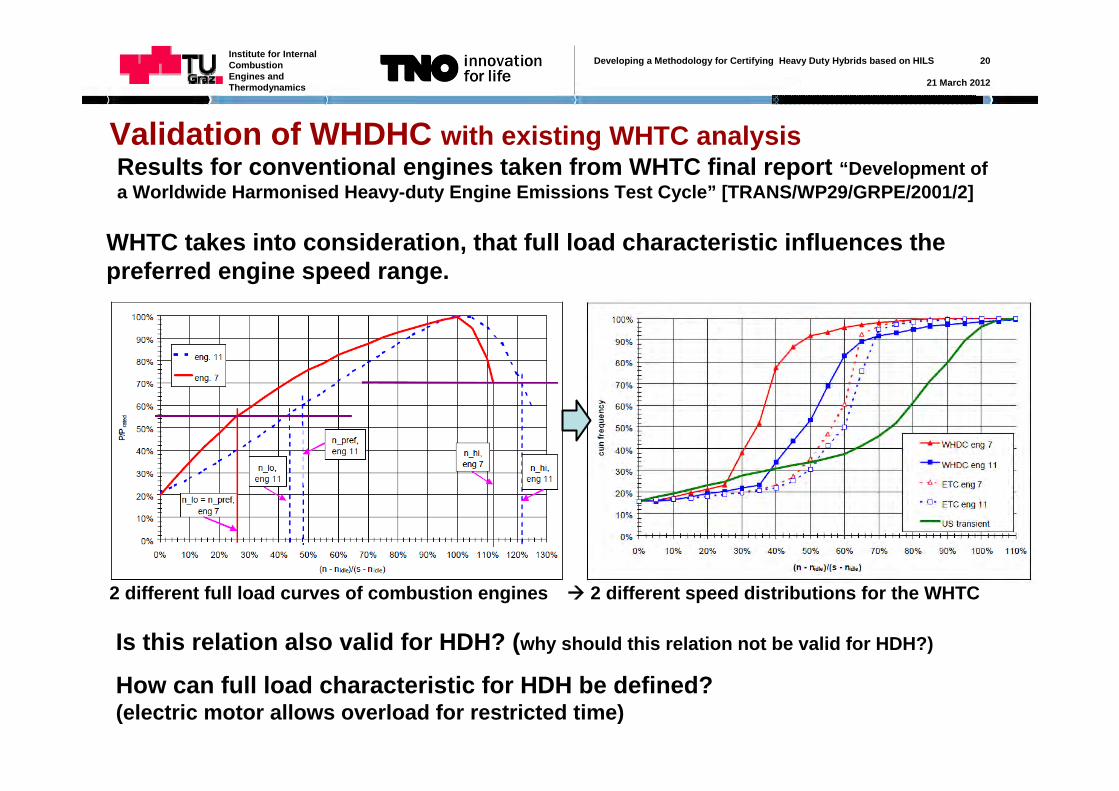
Validation of WHDHC with existing WHTC analysisResults for conventional engines taken from WHTC final report “Development of a Worldwide Harmonised Heavy-duty Engine Emissions Test Cycle” [TRANS/WP29/GRPE/2001/2]
WHTC takes into consideration, that full load characteristic influences the preferred engine speed range.
2 different full load curves of combustion engines 2 different speed distributions for the WHTC
Is this relation also valid for HDH? (why should this relation not be valid for HDH?)
How can full load characteristic for HDH be defined?(electric motor allows overload for restricted time)
Developing a Methodology for Certifying Heavy Duty Hybrids based on HILS 21
21 March 2012
Institute for Internal Combustion Engines and Thermodynamics
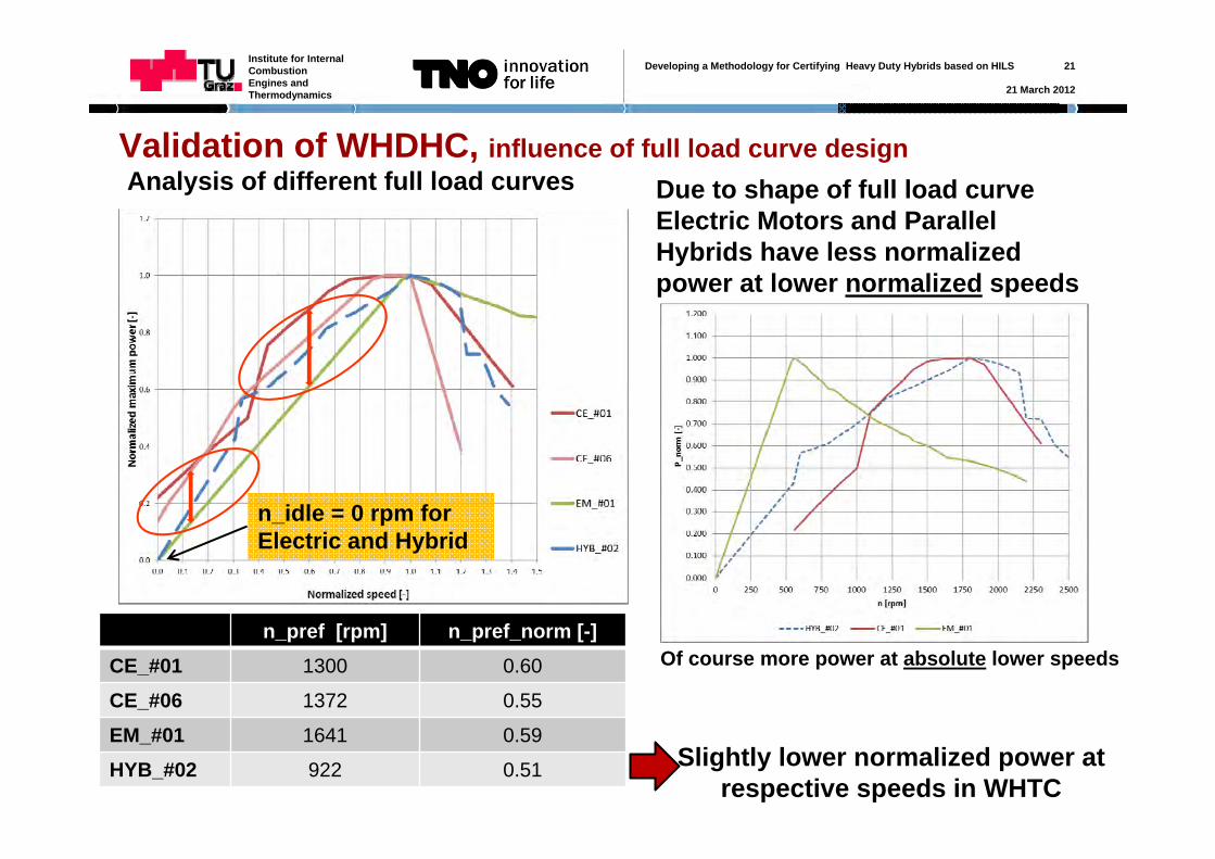
Validation of WHDHC, influence of full load curve designAnalysis of different full load curves Due to shape of full load curve
Electric Motors and Parallel Hybrids have less normalized power at lower normalized speeds
Slightly lower normalized power at respective speeds in WHTC
Of course more power at absolute lower speedsn_pref [rpm] n_pref_norm [-]
CE_#01 1300 0.60
CE_#06 1372 0.55
EM_#01 1641 0.59
HYB_#02 922 0.51
n_idle = 0 rpm for Electric and Hybrid
Developing a Methodology for Certifying Heavy Duty Hybrids based on HILS 22
21 March 2012
Institute for Internal Combustion Engines and Thermodynamics
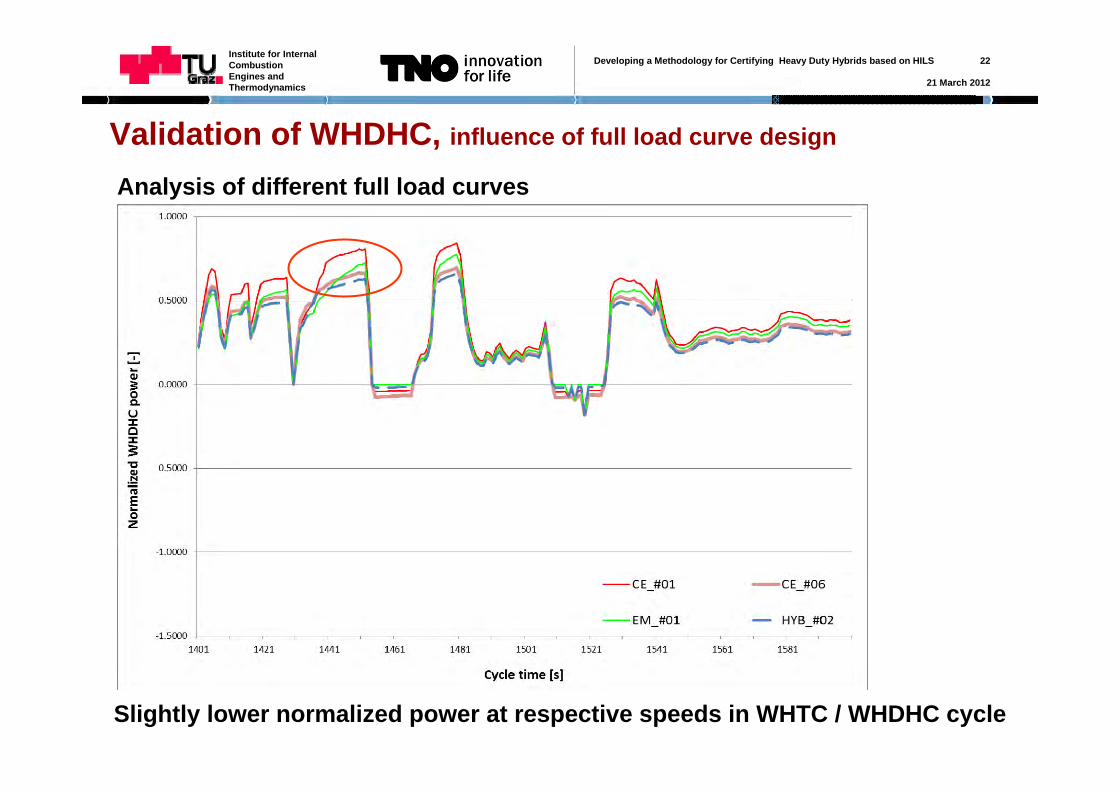
Validation of WHDHC, influence of full load curve design
Analysis of different full load curves
Slightly lower normalized power at respective speeds in WHTC / WHDHC cycle
Developing a Methodology for Certifying Heavy Duty Hybrids based on HILS 23
21 March 2012
Institute for Internal Combustion Engines and Thermodynamics
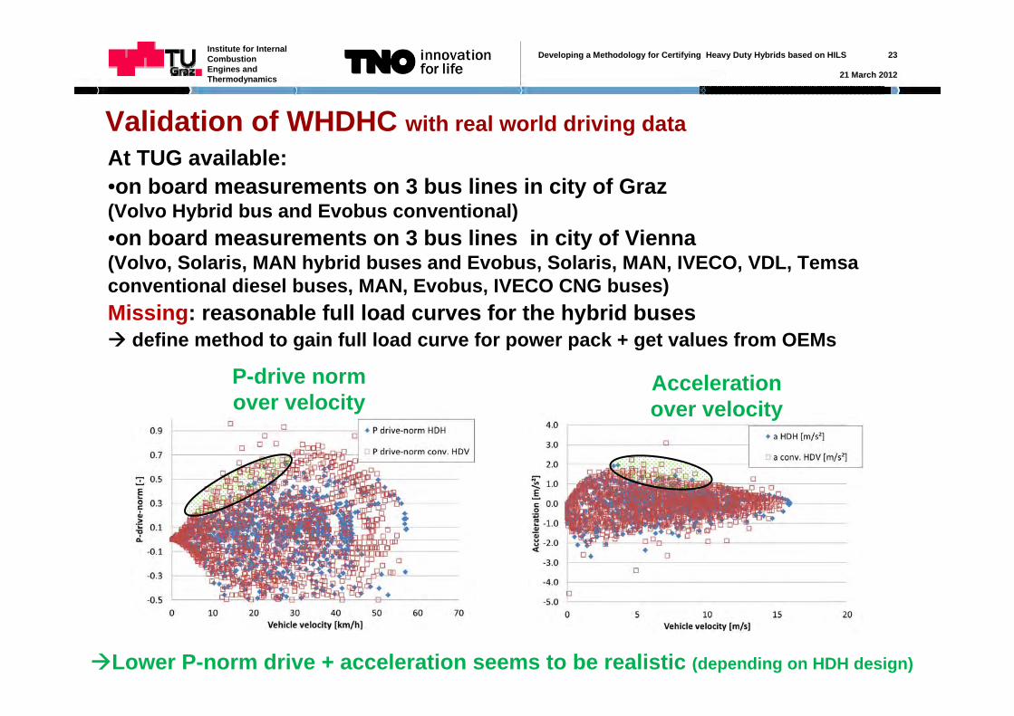
Validation of WHDHC with real world driving dataAt TUG available: •on board measurements on 3 bus lines in city of Graz(Volvo Hybrid bus and Evobus conventional)•on board measurements on 3 bus lines in city of Vienna(Volvo, Solaris, MAN hybrid buses and Evobus, Solaris, MAN, IVECO, VDL, Temsa conventional diesel buses, MAN, Evobus, IVECO CNG buses)Missing: reasonable full load curves for the hybrid buses define method to gain full load curve for power pack + get values from OEMs
P-drive norm over velocity
Accelerationover velocity
Lower P-norm drive + acceleration seems to be realistic (depending on HDH design)
Developing a Methodology for Certifying Heavy Duty Hybrids based on HILS 24
21 March 2012
Institute for Internal Combustion Engines and Thermodynamics
Next steps for WHDHC
• Must: Define method to set up full load curve for hybrid power pack!
• Must: Discuss methods and open questions with (OEM) experts (until now we had no possibility for meetings with experts)
Developing a Methodology for Certifying Heavy Duty Hybrids based on HILS 25
21 March 2012
Institute for Internal Combustion Engines and Thermodynamics
Measured Pe-norm
Sim
ulat
ed P
e-no
rm
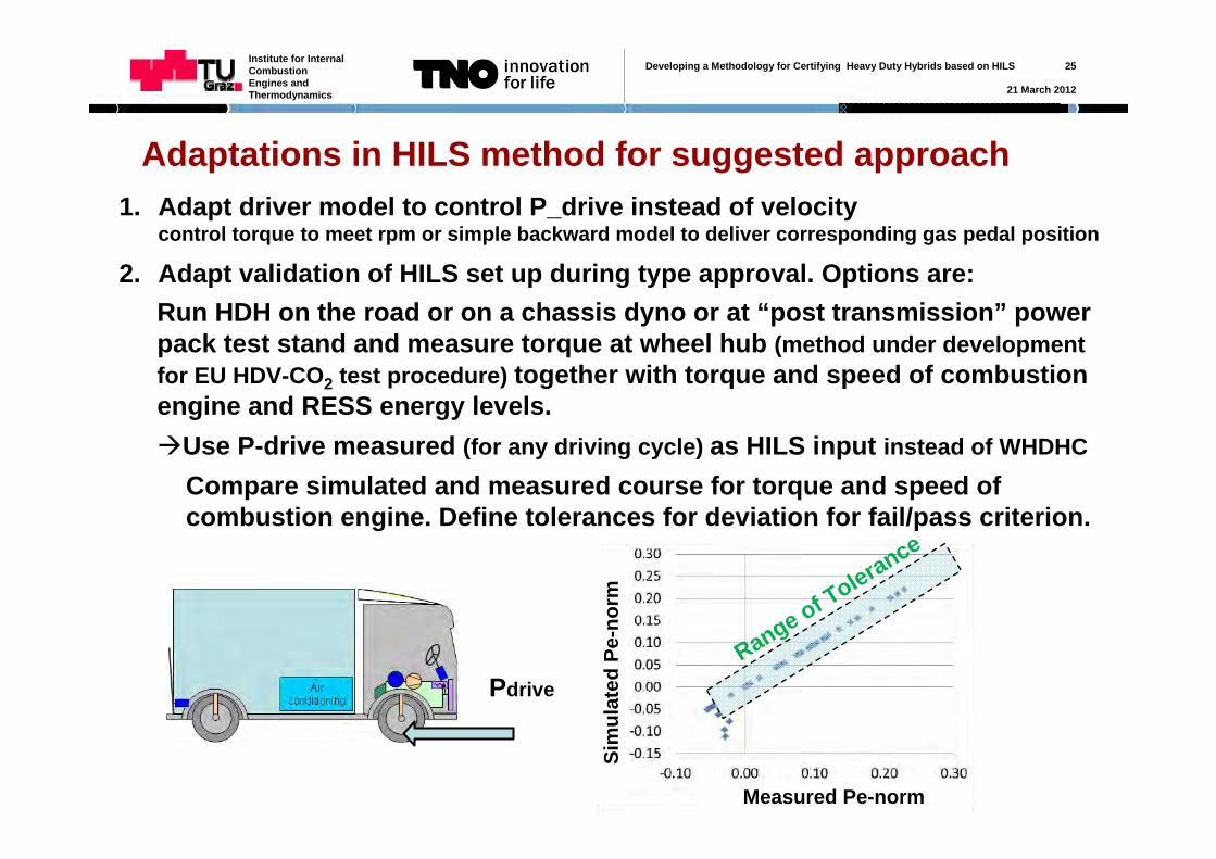
Pdrive
Adaptations in HILS method for suggested approach1. Adapt driver model to control P_drive instead of velocity
control torque to meet rpm or simple backward model to deliver corresponding gas pedal position
2. Adapt validation of HILS set up during type approval. Options are:Run HDH on the road or on a chassis dyno or at “post transmission” power pack test stand and measure torque at wheel hub (method under development for EU HDV-CO2 test procedure) together with torque and speed of combustion engine and RESS energy levels.Use P-drive measured (for any driving cycle) as HILS input instead of WHDHC
Compare simulated and measured course for torque and speed of combustion engine. Define tolerances for deviation for fail/pass criterion.
Range of Tolerance
Developing a Methodology for Certifying Heavy Duty Hybrids based on HILS 26
21 March 2012
Institute for Internal Combustion Engines and Thermodynamics
WHVC weighting factors, HDV classes in HDV-CO2 test procedure (1/9)
Final report: „Reduction and Testing of Greenhouse Gas Emissions from Heavy Duty Vehicles - LOT 2”
“LOT 3” shall start soon to finalise the test procedure and perform pilot test phase
Classes still may change before introduction!
Weighting factors for different vehicle categories need several definitions and data:
•Definition of „vehicle classification“
•Representative „real world“ driving cycles for each class to compare with the WHVC
Corresponding work is performed in course of the development of an European CO2 test procedure for HDV
Next 3 slides are taken from the Final report of LOT 2
Developing a Methodology for Certifying Heavy Duty Hybrids based on HILS 27
21 March 2012
Institute for Internal Combustion Engines and Thermodynamics
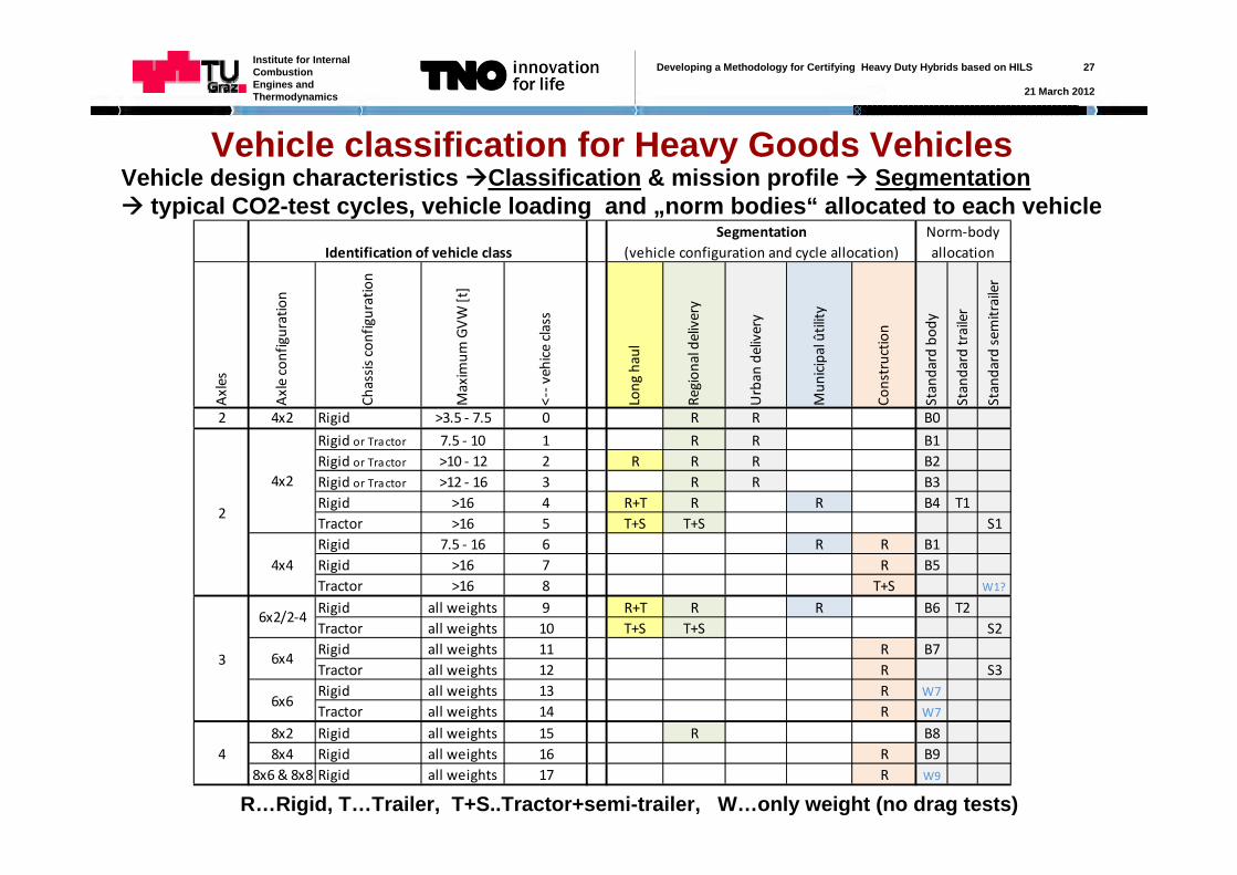
Vehicle classification for Heavy Goods VehiclesVehicle design characteristics Classification & mission profile Segmentation typical CO2-test cycles, vehicle loading and „norm bodies“ allocated to each vehicle
R…Rigid, T…Trailer, T+S..Tractor+semi-trailer, W…only weight (no drag tests)
Axles
Axle configuration
Chassis configuration
Maximum
GVW [t]
<‐‐ vehice class
Long
haul
Region
al delivery
Urban
delivery
Mun
icipal ûtility
Constructio
n
Standard bod
y
Standard trailer
Standard sem
itrailer
2 4x2 Rigid >3.5 ‐ 7.5 0 R R B0
Rigid or Tractor 7.5 ‐ 10 1 R R B1Rigid or Tractor >10 ‐ 12 2 R R R B2Rigid or Tractor >12 ‐ 16 3 R R B3Rigid >16 4 R+T R R B4 T1Tractor >16 5 T+S T+S S1Rigid 7.5 ‐ 16 6 R R B1Rigid >16 7 R B5Tractor >16 8 T+S W1?
Rigid all weights 9 R+T R R B6 T2Tractor all weights 10 T+S T+S S2Rigid all weights 11 R B7Tractor all weights 12 R S3Rigid all weights 13 R W7
Tractor all weights 14 R W7
8x2 Rigid all weights 15 R B88x4 Rigid all weights 16 R B9
8x6 & 8x8 Rigid all weights 17 R W9
2
4x2
4x4
Segmentation (vehicle configuration and cycle allocation)Identification of vehicle class
Norm‐body allocation
3
6x2/2‐4
6x4
6x6
4
Developing a Methodology for Certifying Heavy Duty Hybrids based on HILS 28
21 March 2012
Institute for Internal Combustion Engines and Thermodynamics
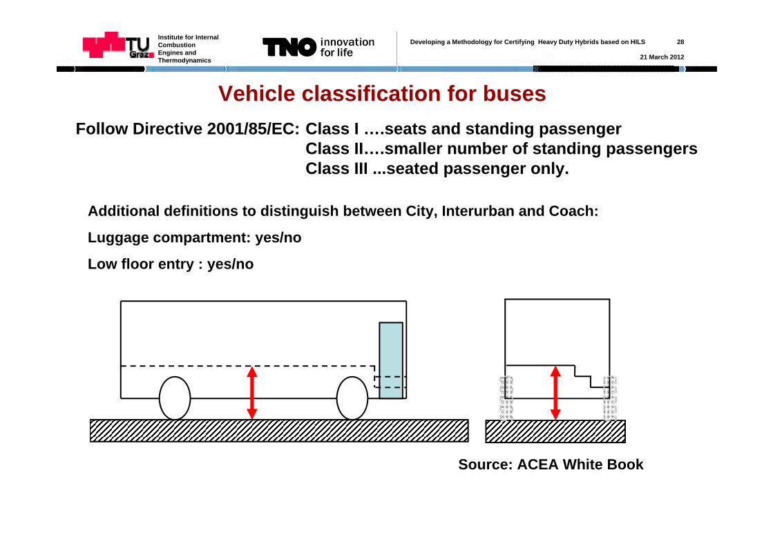
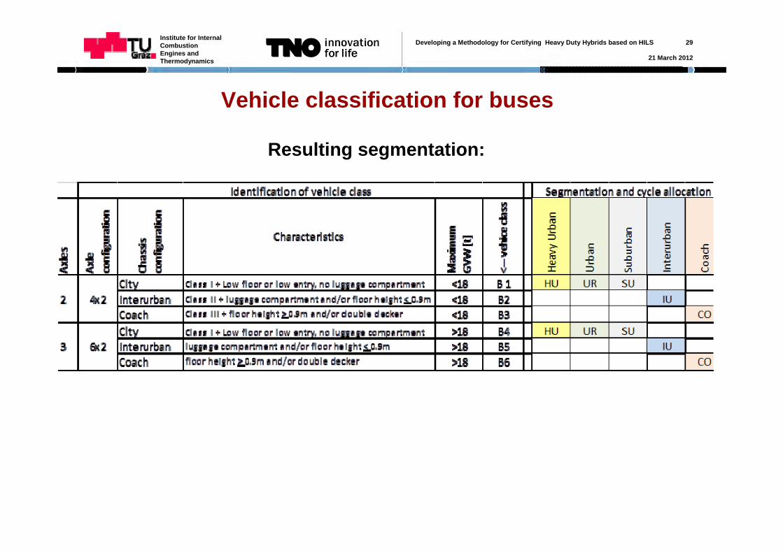
Vehicle classification for busesFollow Directive 2001/85/EC: Class I ….seats and standing passenger
Class II….smaller number of standing passengers Class III ...seated passenger only.
Additional definitions to distinguish between City, Interurban and Coach:
Luggage compartment: yes/no
Low floor entry : yes/no
Source: ACEA White Book
Developing a Methodology for Certifying Heavy Duty Hybrids based on HILS 29
21 March 2012
Institute for Internal Combustion Engines and Thermodynamics
Vehicle classification for buses
Resulting segmentation:
Developing a Methodology for Certifying Heavy Duty Hybrids based on HILS 30
21 March 2012
Institute for Internal Combustion Engines and Thermodynamics
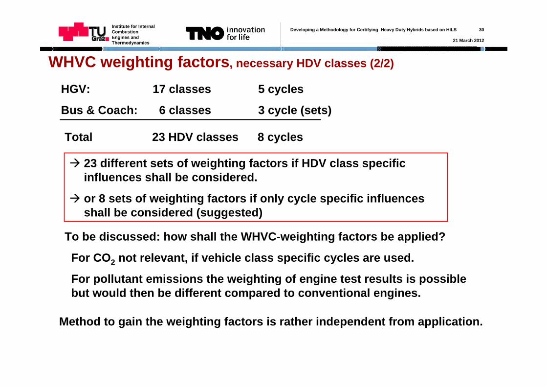
HGV: 17 classes 5 cycles
Bus & Coach: 6 classes 3 cycle (sets)
23 different sets of weighting factors if HDV class specific influences shall be considered.
or 8 sets of weighting factors if only cycle specific influencesshall be considered (suggested)
Total 23 HDV classes 8 cycles
To be discussed: how shall the WHVC-weighting factors be applied?
For CO2 not relevant, if vehicle class specific cycles are used.
For pollutant emissions the weighting of engine test results is possible but would then be different compared to conventional engines.
Method to gain the weighting factors is rather independent from application.
WHVC weighting factors, necessary HDV classes (2/2)
Developing a Methodology for Certifying Heavy Duty Hybrids based on HILS 31
21 March 2012
Institute for Internal Combustion Engines and Thermodynamics
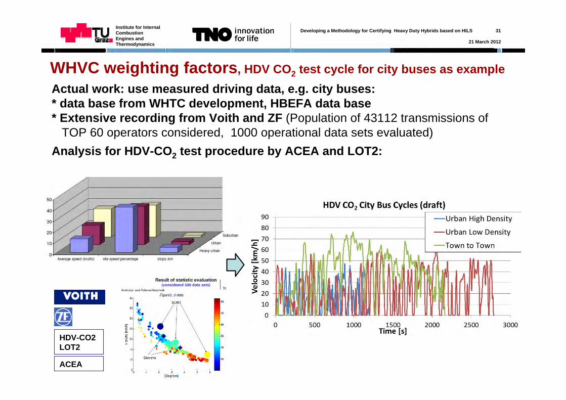
WHVC weighting factors, HDV CO2 test cycle for city buses as example Actual work: use measured driving data, e.g. city buses:* data base from WHTC development, HBEFA data base* Extensive recording from Voith and ZF (Population of 43112 transmissions of
TOP 60 operators considered, 1000 operational data sets evaluated)Analysis for HDV-CO2 test procedure by ACEA and LOT2:
HDV-CO2 LOT2
ACEA
Developing a Methodology for Certifying Heavy Duty Hybrids based on HILS 32
21 March 2012
Institute for Internal Combustion Engines and Thermodynamics
MinimumKPKPi
KPiKPiWFWF Tot
Motorway
RoadUrbann i RS
nWHVCRSKinWHVC
,
j Kin.Param
1 Kin.Param
2
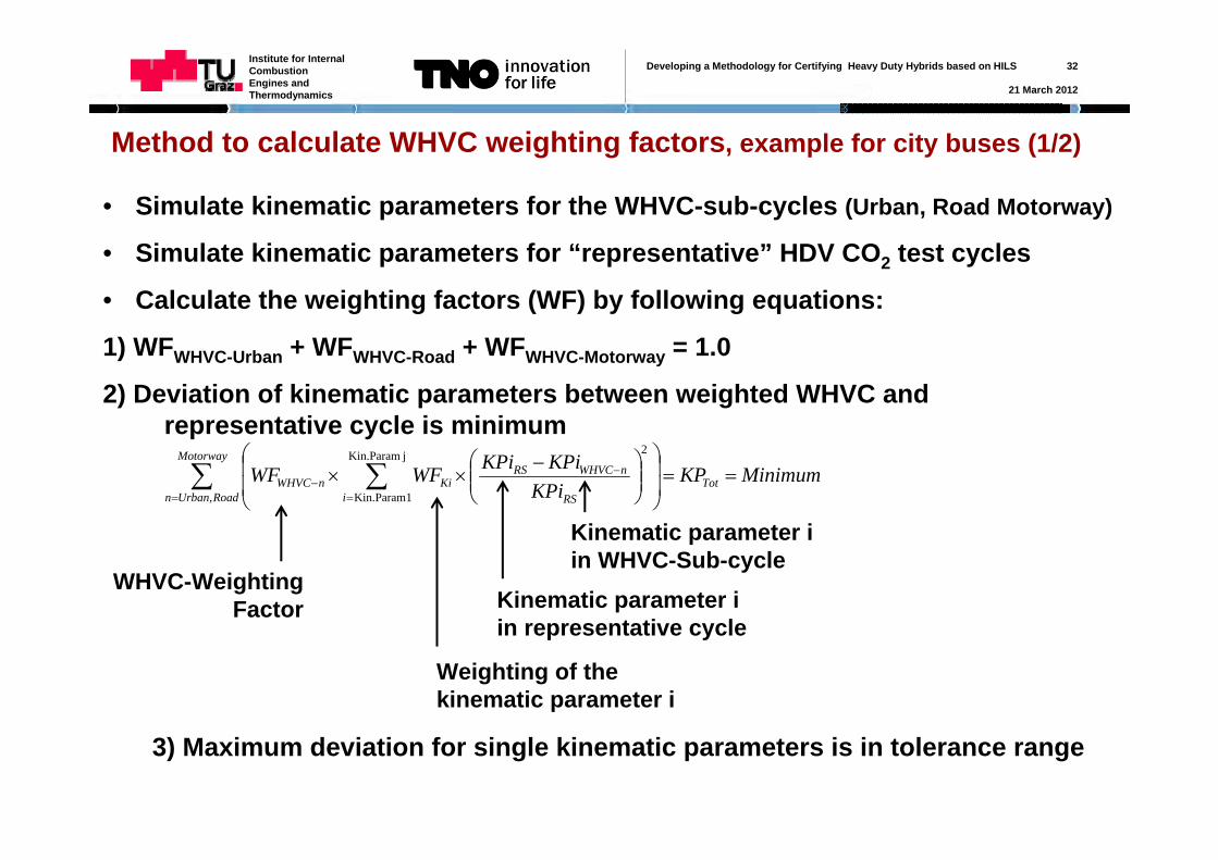
Method to calculate WHVC weighting factors, example for city buses (1/2)
• Simulate kinematic parameters for the WHVC-sub-cycles (Urban, Road Motorway)
• Simulate kinematic parameters for “representative” HDV CO2 test cycles
• Calculate the weighting factors (WF) by following equations:
1) WFWHVC-Urban + WFWHVC-Road + WFWHVC-Motorway = 1.0
2) Deviation of kinematic parameters between weighted WHVC and representative cycle is minimum
WHVC-Weighting Factor
Kinematic parameter iin WHVC-Sub-cycle
Kinematic parameter iin representative cycle
Weighting of the kinematic parameter i
3) Maximum deviation for single kinematic parameters is in tolerance range
Developing a Methodology for Certifying Heavy Duty Hybrids based on HILS 33
21 March 2012
Institute for Internal Combustion Engines and Thermodynamics
WF_WHVC KPtot WF_WHVC KPtot WF_WHVC KPtot
WHVC_urban 0.34 0.7 1WHVC_rural 0.33 0.2 0
WHVC_motorway 0.33 0.544 0.1 0.3414 0 0.0997
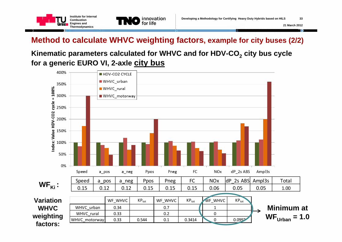
Method to calculate WHVC weighting factors, example for city buses (2/2)
Kinematic parameters calculated for WHVC and for HDV-CO2 city bus cycle for a generic EURO VI, 2-axle city bus
Speed a_pos a_neg Ppos Pneg FC NOx dP_2s ABS Ampl3s Total0.15 0.12 0.12 0.15 0.15 0.15 0.06 0.05 0.05 1.00WFKi :
Variation WHVC
weighting factors:
Minimum at WFUrban = 1.0
Developing a Methodology for Certifying Heavy Duty Hybrids based on HILS 34
21 March 2012
Institute for Internal Combustion Engines and Thermodynamics
Next steps for WHVC weighting factors
• HDV CO2 test cycles still under development
• As soon as the cycles are available, the method described before will be applied to calculate the corresponding weighting factors for each HDV class
• This work is included in the actual project and should be finalised until end of 2012 (cycles from HDV-CO2 project not to be expected before end 2012)
Description of method in final report from TUG until June 2012
Report with results for all classes provided by TUG later without additional budget demand
Developing a Methodology for Certifying Heavy Duty Hybrids based on HILS 35
21 March 2012
Institute for Internal Combustion Engines and Thermodynamics
Including PTO into the test procedure (1/9)
PTO power demand is not included in WHTC test cycle for conventional engines.From the options analysed yet to include PTO in the WHDHC method, not any seems to be reasonable for pollutant emissions:Basic assumption: the hybrid vehicle has less engine power demand due to PTO operation than a conventional vehicle options:•Since WHTC has zero load at idling, a “PTO reduction factor” can not be applied where it should be applied for many HDV categories, i.e. at idling. •As alternative the P_drive curve as input to the HILS model could be reduced.•Reduced P_drive does not depicture real situation accordingly, since it would avoid all full load situations for the combustion engineGeneral: •Small variations on cycle work show minor influences on g/kWh results•To obtain the “PTO reduction factor” a high effort is necessary (e.g. applying method applied by US EPA, 40 CFR 1037.525.)
Developing a Methodology for Certifying Heavy Duty Hybrids based on HILS 36
21 March 2012
Institute for Internal Combustion Engines and Thermodynamics
Including PTO into the test procedure Suggestion:Elaborate method to consider PTO in the CO2 test procedure for HDH and for conventional HDV in comparable way, i.e. Option a) include PTO load cycle(s) in simulatorOption b) follow US approach (measure PTO on HDH and on conventional HDV)
HDV categories to be considered:
•Garbage trucks (compression work)
•City bus (air conditioning system; this would allow to include in future also efficiency of AC system and glazing quality in the CO2 test procedure)
•Municipal utility (extra load cycle necessary, e.g. road sweepers or like garbage truck cycle?)
•Construction (e.g. work of a crane)
•Others?Example for option a) elaborated by TUG in the contract (city bus due to data availability)
Example for and experience on option b) available at US EPA (?)
Developing a Methodology for Certifying Heavy Duty Hybrids based on HILS 37
21 March 2012
Institute for Internal Combustion Engines and Thermodynamics
Air conditioning for City buses: influencing factorsMechanical driven compressor at conventional enginesElectrical driven at HDH (part load can be controlled by different compressor speed)
Cooling demand depends on:
1.Ambient temperature and humidity
2.Target temperature in the cabin
3.Sun radiation & area and quality of glazing
4.Air mass flow through AC system and % recirculated air
5.Technology of the air conditioning system
AC compressor power demand to provide cooling capacity = load cycle.HILS model would need to provide this power by electric motor or by mechanical connection to engineInfluences 1. to 4. have to be considered when load cycle for AC is defined.No data found in literature yet on these influences Simulation of variability in cooling capacity demand (CAP) and resulting
compressor work
Developing a Methodology for Certifying Heavy Duty Hybrids based on HILS 38
21 March 2012
Institute for Internal Combustion Engines and Thermodynamics
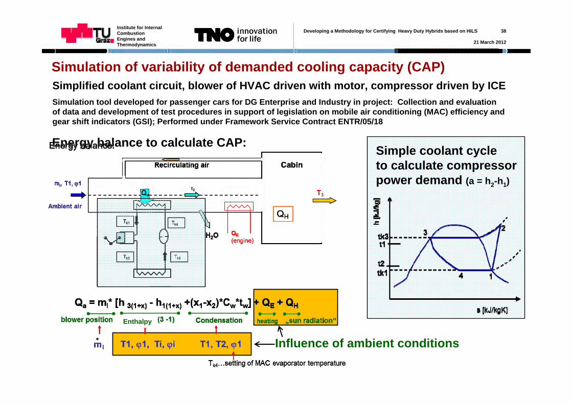
Simulation of variability of demanded cooling capacity (CAP)Simplified coolant circuit, blower of HVAC driven with motor, compressor driven by ICESimulation tool developed for passenger cars for DG Enterprise and Industry in project: Collection and evaluation of data and development of test procedures in support of legislation on mobile air conditioning (MAC) efficiency and gear shift indicators (GSI); Performed under Framework Service Contract ENTR/05/18
Energy balance to calculate CAP: Simple coolant cycleto calculate compressor power demand (a = h2-h1)
Influence of ambient conditions
Enthalpy
Developing a Methodology for Certifying Heavy Duty Hybrids based on HILS 39
21 March 2012
Institute for Internal Combustion Engines and Thermodynamics
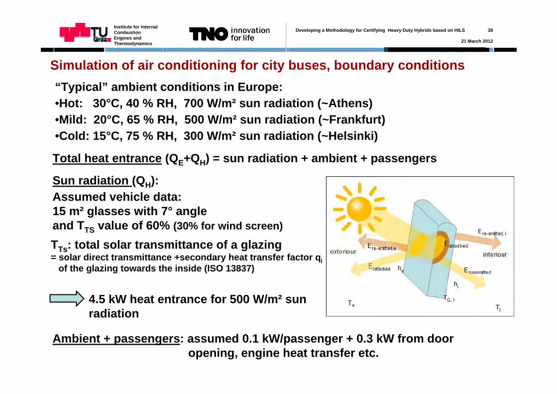
Simulation of air conditioning for city buses, boundary conditions“Typical” ambient conditions in Europe:•Hot: 30°C, 40 % RH, 700 W/m² sun radiation (~Athens)•Mild: 20°C, 65 % RH, 500 W/m² sun radiation (~Frankfurt)•Cold: 15°C, 75 % RH, 300 W/m² sun radiation (~Helsinki)
Total heat entrance (QE+QH) = sun radiation + ambient + passengers
Sun radiation (QH):Assumed vehicle data:15 m² glasses with 7° angle and TTS value of 60% (30% for wind screen)
TTs: total solar transmittance of a glazing= solar direct transmittance +secondary heat transfer factor qi
of the glazing towards the inside (ISO 13837)
4.5 kW heat entrance for 500 W/m² sun radiation
Ambient + passengers: assumed 0.1 kW/passenger + 0.3 kW from door opening, engine heat transfer etc.
Developing a Methodology for Certifying Heavy Duty Hybrids based on HILS 40
21 March 2012
Institute for Internal Combustion Engines and Thermodynamics
Simulation of air conditioning for city buses, boundary conditions
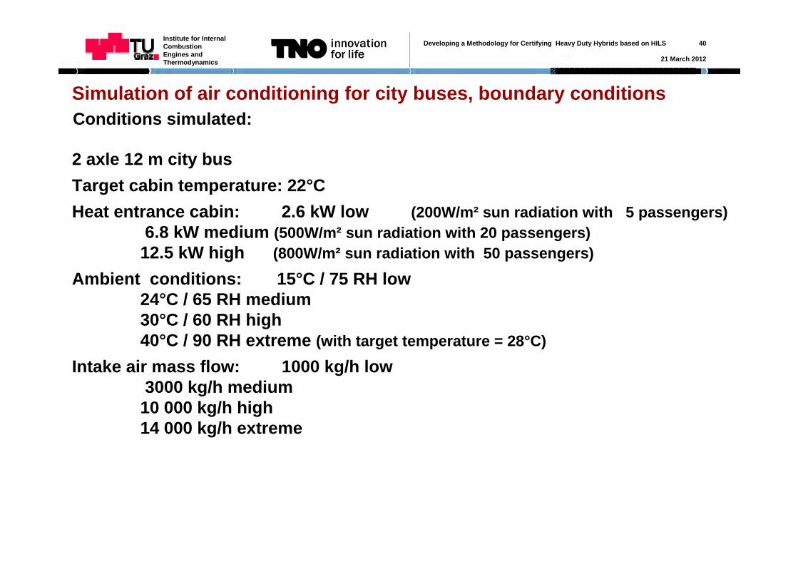
2 axle 12 m city busTarget cabin temperature: 22°CHeat entrance cabin: 2.6 kW low (200W/m² sun radiation with 5 passengers)
6.8 kW medium (500W/m² sun radiation with 20 passengers)12.5 kW high (800W/m² sun radiation with 50 passengers)
Ambient conditions: 15°C / 75 RH low24°C / 65 RH medium30°C / 60 RH high40°C / 90 RH extreme (with target temperature = 28°C)
Intake air mass flow: 1000 kg/h low3000 kg/h medium10 000 kg/h high 14 000 kg/h extreme
Conditions simulated:
Developing a Methodology for Certifying Heavy Duty Hybrids based on HILS 41
21 March 2012
Institute for Internal Combustion Engines and Thermodynamics
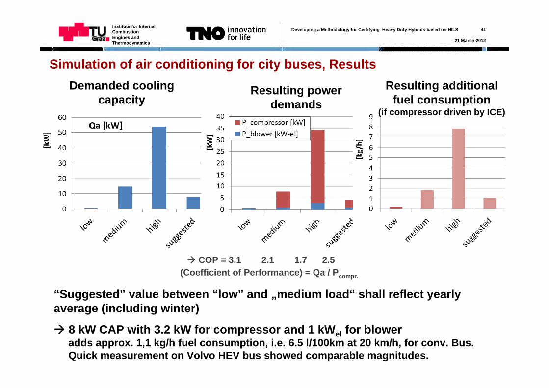
Simulation of air conditioning for city buses, ResultsDemanded cooling
capacityResulting power
demands
(Coefficient of Performance) = Qa / Pcompr.
COP = 3.1 2.1 1.7 2.5
“Suggested” value between “low” and „medium load“ shall reflect yearly average (including winter)
8 kW CAP with 3.2 kW for compressor and 1 kWel for blower adds approx. 1,1 kg/h fuel consumption, i.e. 6.5 l/100km at 20 km/h, for conv. Bus.Quick measurement on Volvo HEV bus showed comparable magnitudes.
Resulting additional fuel consumption
(if compressor driven by ICE)
Developing a Methodology for Certifying Heavy Duty Hybrids based on HILS 42
21 March 2012
Institute for Internal Combustion Engines and Thermodynamics
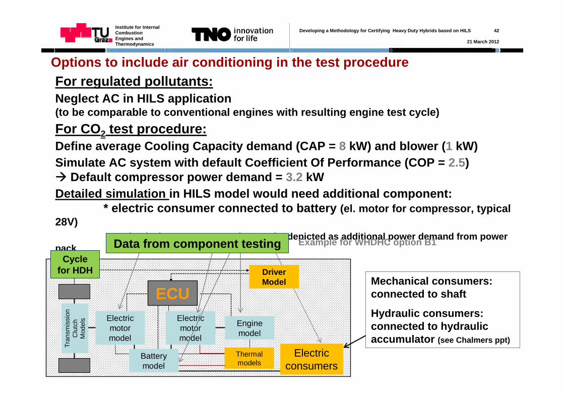
Options to include air conditioning in the test procedureFor regulated pollutants:Neglect AC in HILS application(to be comparable to conventional engines with resulting engine test cycle)For CO2 test procedure:Define average Cooling Capacity demand (CAP = 8 kW) and blower (1 kW)Simulate AC system with default Coefficient Of Performance (COP = 2.5) Default compressor power demand = 3.2 kWDetailed simulation in HILS model would need additional component:
* electric consumer connected to battery (el. motor for compressor, typical 28V)
mechanical power consumption can be depicted as additional power demand from power pack
Electric consumers
Mechanical consumers: connected to shaft
Hydraulic consumers:connected to hydraulic accumulator (see Chalmers ppt)
Electric motor model
Electric motor model
Engine model
Tran
smis
sion
Clu
tch
Mod
els
ECU-Model
Driver Model
Pwheel drive
Battery model
Thermal models
ECU
Cycle for HDH
Data from component testing Example for WHDHC option B1
Developing a Methodology for Certifying Heavy Duty Hybrids based on HILS 43
21 March 2012
Institute for Internal Combustion Engines and Thermodynamics
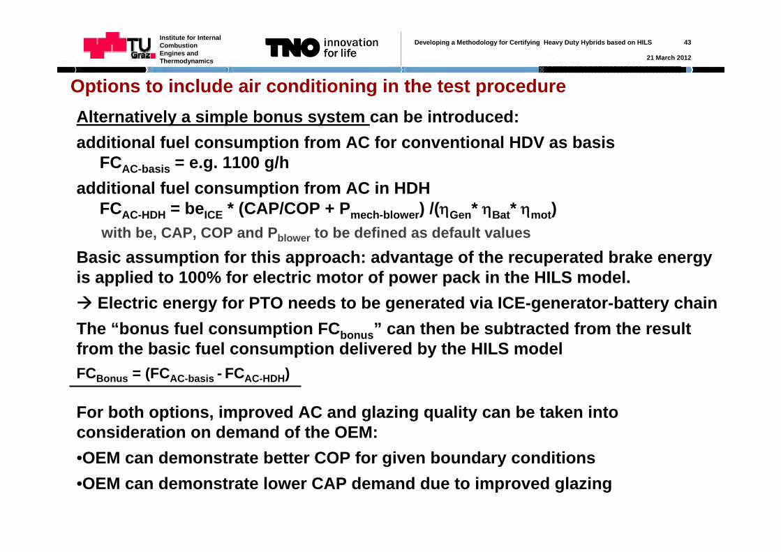
Options to include air conditioning in the test procedureAlternatively a simple bonus system can be introduced:additional fuel consumption from AC for conventional HDV as basis
FCAC-basis = e.g. 1100 g/hadditional fuel consumption from AC in HDH
FCAC-HDH = beICE * (CAP/COP + Pmech-blower) /(Gen* Bat* mot) with be, CAP, COP and Pblower to be defined as default values
Basic assumption for this approach: advantage of the recuperated brake energy is applied to 100% for electric motor of power pack in the HILS model. Electric energy for PTO needs to be generated via ICE-generator-battery chain The “bonus fuel consumption FCbonus” can then be subtracted from the result from the basic fuel consumption delivered by the HILS model FCBonus = (FCAC-basis - FCAC-HDH)
For both options, improved AC and glazing quality can be taken into consideration on demand of the OEM:•OEM can demonstrate better COP for given boundary conditions•OEM can demonstrate lower CAP demand due to improved glazing
Developing a Methodology for Certifying Heavy Duty Hybrids based on HILS 44
21 March 2012
Institute for Internal Combustion Engines and Thermodynamics
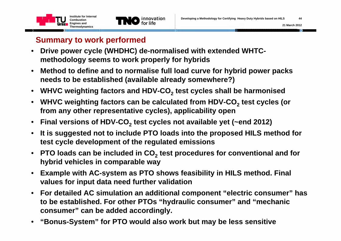
Summary to work performed• Drive power cycle (WHDHC) de-normalised with extended WHTC-
methodology seems to work properly for hybrids• Method to define and to normalise full load curve for hybrid power packs
needs to be established (available already somewhere?)• WHVC weighting factors and HDV-CO2 test cycles shall be harmonised• WHVC weighting factors can be calculated from HDV-CO2 test cycles (or
from any other representative cycles), applicability open• Final versions of HDV-CO2 test cycles not available yet (~end 2012)• It is suggested not to include PTO loads into the proposed HILS method for
test cycle development of the regulated emissions• PTO loads can be included in CO2 test procedures for conventional and for
hybrid vehicles in comparable way• Example with AC-system as PTO shows feasibility in HILS method. Final
values for input data need further validation• For detailed AC simulation an additional component “electric consumer” has
to be established. For other PTOs “hydraulic consumer” and “mechanic consumer” can be added accordingly.
• “Bonus-System” for PTO would also work but may be less sensitive
Developing a Methodology for Certifying Heavy Duty Hybrids based on HILS 45
21 March 2012
Institute for Internal Combustion Engines and Thermodynamics
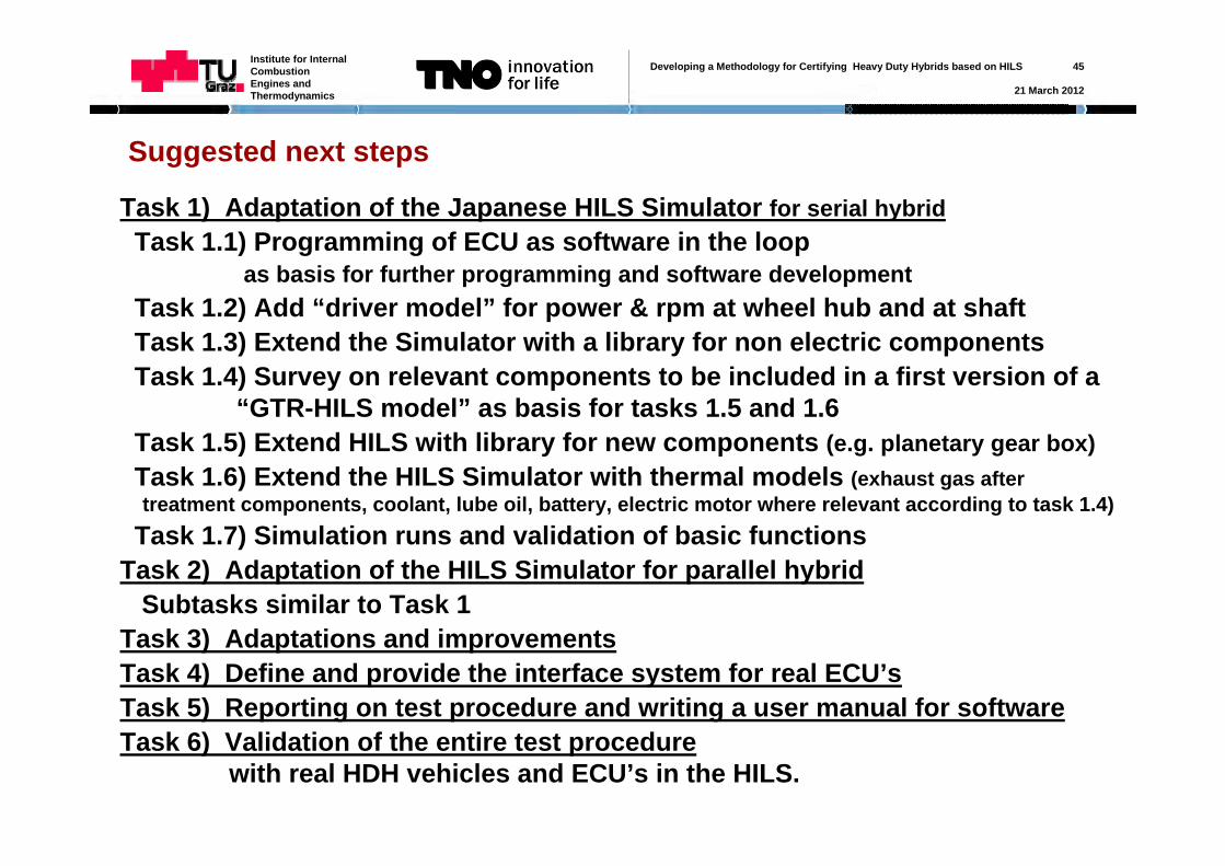
Task 1) Adaptation of the Japanese HILS Simulator for serial hybridTask 1.1) Programming of ECU as software in the loop
as basis for further programming and software developmentTask 1.2) Add “driver model” for power & rpm at wheel hub and at shaftTask 1.3) Extend the Simulator with a library for non electric componentsTask 1.4) Survey on relevant components to be included in a first version of a
“GTR-HILS model” as basis for tasks 1.5 and 1.6Task 1.5) Extend HILS with library for new components (e.g. planetary gear box)Task 1.6) Extend the HILS Simulator with thermal models (exhaust gas after treatment components, coolant, lube oil, battery, electric motor where relevant according to task 1.4)
Task 1.7) Simulation runs and validation of basic functionsTask 2) Adaptation of the HILS Simulator for parallel hybrid
Subtasks similar to Task 1Task 3) Adaptations and improvements Task 4) Define and provide the interface system for real ECU’sTask 5) Reporting on test procedure and writing a user manual for softwareTask 6) Validation of the entire test procedure
with real HDH vehicles and ECU’s in the HILS.
Suggested next steps

Developing a Methodology for Certifying Heavy Duty Hybrids based on HILS 46
21 March 2012
Institute for Internal Combustion Engines and Thermodynamics
Thank you for your attention!