Embed Size (px)
DESCRIPTION
A very low loss tunable evanescent-mode cavity bandpass filter (BPF) with one-octave (6–12 GHz) tuning range ispresented. In order to implement a very low insertion loss withwideband operation, a new coaxial feed structure is devised inthe tunable BPF. Across the entire tuning range, the achievedinsertion loss is less than 0.5 dB. The tunability is realized by usingsilicon microelectromechanical systems (MEMS) diaphragmswith slits that are electrostatically actuated.
Citation preview
1
Development of 6–12 GHz Low-Loss, Tunable BandPass Filter for Pre-LNA Interference Rejection
Young Seek Cho, Member, IEEE, Himanshu Joshi, Member, IEEE, Xiaoguang Liu, Member, IEEE,Hjalti H. Sigmarsson, Member, IEEE, William J. Chappell, Member, IEEE, and Dimitrios Peroulis, Member, IEEE
Abstract—A very low loss tunable evanescent-mode cavity bandpass filter (BPF) with one-octave (6–12 GHz) tuning range ispresented. In order to implement a very low insertion loss withwideband operation, a new coaxial feed structure is devised inthe tunable BPF. Across the entire tuning range, the achievedinsertion loss is less than 0.5 dB. The tunability is realized by us-ing silicon microelectromechanical systems (MEMS) diaphragmswith slits that are electrostatically actuated.
Index Terms—Tunable filter, MEMS, RF-MEMS
I. INTRODUCTION
RAPID growth in demand for multi-band and multi-standard RF front-end modules has accelerated research
activities, especially on the implementation of reconfigurableRF filters. Such activities resulted in a 12–18 GHz three-pole tunable filter that was implemented using RF MEMScapacitive switches with loaded resonators [1]. Piezoelectricdisks were used on substrate integrated evanescent-mode cav-ities to create a tunable filter with tuning range of 0.98–3.48 GHz [2]. While a wide tuning range is highly desirable,RF filter performance such as low passband insertion loss andhigh stopband attenuation is needed in a small form factor.One of the critical design factors for the desired performanceis a high unloaded quality factor (Qu).
Heavily-loaded evanescent-mode cavity filters offer a veryattractive solution for achieving high performance in a smallform factor. A previous characterization of loaded evanescent-mode cavity resonators has been reported in [3]. The resonantfrequency and Qu are determined by the dimensions of thecavity, the loading post, and the gap between the post top andthe cavity ceiling. When the gap is very small, the resonantfrequency of the resonator is strongly dependent on the gap.If the cavity ceiling can be deflected by an external force, theresonant frequency can be tuned [4].
A high-Q tunable evanescent-mode cavity filter usingsingle-crystal silicon RF MEMS diaphragms has been demon-strated to verify this concept [5]. All-silicon tunable cavity
Y. S. Cho is with the Center for Advanced Electric Applications, WonkwangUniversity, Iksan, 570-749 Republic of Korea (e-mail: [email protected]).
X. Liu is with the Department of Electrical and Computer Engi-neering, University of California Davis, Davis, CA 95616 USA (e-mail:[email protected]).
H. Joshi and H. H. Sigmarsson are with the School of Electrical andComputer Engineering, University of Oklahoma, Norman, OK 73019 USA(e-mail: [email protected]).
W. J. Chappell, and D. Peroulis are with the School of Electrical andComputer Engineering, Purdue University, West Lafayette, IN 47907 USA(e-mail: [email protected]; [email protected]).
Manuscript received January 10, 2014.
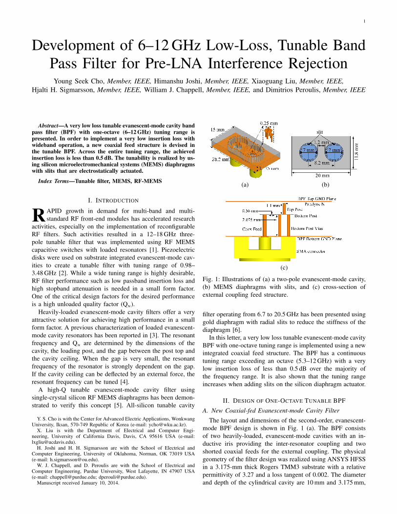
(a) (b)
(c)
Fig. 1: Illustrations of (a) a two-pole evanescent-mode cavity,(b) MEMS diaphragms with slits, and (c) cross-section ofexternal coupling feed structure.
filter operating from 6.7 to 20.5 GHz has been presented usinggold diaphragm with radial slits to reduce the stiffness of thediaphragm [6].
In this letter, a very low loss tunable evanescent-mode cavityBPF with one-octave tuning range is implemented using a newintegrated coaxial feed structure. The BPF has a continuoustuning range exceeding an octave (5.3–12 GHz) with a verylow insertion loss of less than 0.5 dB over the majority ofthe frequency range. It is also shown that the tuning rangeincreases when adding slits on the silicon diaphragm actuator.
II. DESIGN OF ONE-OCTAVE TUNABLE BPF
A. New Coaxial-fed Evanescent-mode Cavity Filter
The layout and dimensions of the second-order, evanescent-mode BPF design is shown in Fig. 1 (a). The BPF consistsof two heavily-loaded, evanescent-mode cavities with an in-ductive iris providing the inter-resonator coupling and twoshorted coaxial feeds for the external coupling. The physicalgeometry of the filter design was realized using ANSYS HFSSin a 3.175-mm thick Rogers TMM3 substrate with a relativepermittivity of 3.27 and a loss tangent of 0.002. The diameterand depth of the cylindrical cavity are 10 mm and 3.175 mm,
2
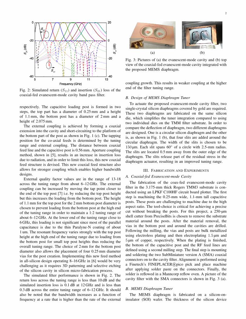
Fig. 2: Simulated return (S11) and insertion (S21) loss of thecoaxial-fed evanescent-mode cavity band pass filter.
respectively. The capacitive loading post is formed in twosteps, the top part has a diameter of 0.25 mm and a heightof 1.1 mm, the bottom post has a diameter of 2 mm and aheight of 2.075 mm.
The external coupling is achieved by forming a coaxialextension into the cavity and short-circuiting to the platform ofthe bottom part of the post as shown in Fig. 1 (c). The tappingposition for the co-axial feeds is determined by the tuningrange and external coupling. The distance between coaxialfeed line and the capacitive post is 0.56 mm. Aperture couplingmethod, shown in [5], results in an increase in insertion lossdue to radiation, and in order to limit this loss, this new coaxialfeed structure is devised. This new coaxial feed structure alsoallows for stronger coupling which enables higher bandwidthdesigns.
External quality factor values are in the range of 13-18across the tuning range from about 6–12 GHz. The externalcoupling can be increased by moving the tap point closer tothe end of the top post [7] i.e. by reducing the top post heightbut this increases the loading from the bottom post. The heightof 1.1 mm for the top post for the 2 mm bottom post diameter ischosen to prevent loading from the bottom post at the high endof the tuning range in order to maintain a 1:2 tuning range ofabout 6–12 GHz. At the lower end of the tuning range close to6 GHz, this loading is not significant since most of the parallelcapacitance is due to the thin Paralyne-N coating of about1 um. The resonant frequency varies strongly with the top postheight at the high end of the tuning range due to loading fromthe bottom post for small top post heights thus reducing theoverall tuning range. The choice of 2 mm for the bottom postdiameter also allows the placement of four 0.25 mm diametervias for the post creation. Implementing this new feed methodin all-silicon design operating 8–16 GHz in [6] would be verychallenging as it requires 3D patterning and selective etchingof the silicon cavity in silicon micro-fabrication process.
The simulated filter performance is shown in Fig. 2. Thereturn loss across the tuning range is less than 10 dB and thesimulated insertion loss is 0.1 dB at 12 GHz and is less than0.3 dB across the entire tuning range of 6–12 GHz. It shouldalso be noted that the bandwidth increases as a function offrequency at a rate that is higher than the rate of the external
(a) (b)
Fig. 3: Pictures of (a) the evanescent-mode cavity and (b) topview of the coaxial-fed evanescent-mode cavity integrated withthe proposed MEMS diaphragm.
coupling growth. This results in weaker coupling at the higherend of the filter tuning range.
B. Design of MEMS Diaphragm Tuner
To actuate the proposed evanescent-mode cavity filter, twosingle-crystal silicon diaphragms covered by gold are required.These two diaphragms are fabricated on the same silicondie, which simplifies the tuner integration compared to usingtwo individual dies on the TMM filter substrate. In order tocompare the deflection of diaphragm, two different diaphragmsare designed. One is a circular silicon diaphragm and the otheris, as shown in Fig. 1 (b), that four slits are added around thecircular diaphragm. The width of the slits is chosen to be150 µm. Each slit spans 60◦ of a circle with 2.5-mm radius.The slits are located 0.5 mm away from the outer edge of thediaphragm. The slits release part of the residual stress in thediaphragm actuator, resulting in an improved tuning range.
III. FABRICATION AND EXPERIMENTS
A. Coaxial-fed Evanescent-mode Cavity
The fabrication of the coax-fed evanescent-mode cavityfilter in the 3.175-mm thick Rogers TMM3 substrate is con-ducted using an LPKF C100HF circuit board plotter. The firststep is machining the 0.25-mm wide, 1.1-mm tall capacitiveposts. These posts are challenging to machine due to the highaspect ratio. The tool-choice is critical for achieving a precisecut without breaking the posts. For this project, a 250-µmshell cutter from PreciseBits is chosen to remove the substratematerial around the posts. After the material removal, thevias in the bottom post and around the cavities are drilled.Following the milling, the vias and posts are bulk metallizedusing electroless plating and then electroplating 1.5 µm and5 µm of copper, respectively. When the plating is finished,the bottom of the capacitive post and the RF feed lines aredefined using a second milling step. The final step is mountingand soldering the two SubMiniature version A (SMA) coaxialconnectors on to the cavity filter. Alignment is performed usinga Finetech’s FINEPLACER R©pico pick and place machineafter applying solder paste on the connectors. Finally, thesolder is reflowed in a Manncorp reflow oven. A picture of thecavity filter with the SMA connectors is shown in Fig. 3 (a).
B. MEMS Diaphragm Tuner
The MEMS diaphragm is fabricated on a silicon-on-insulator (SOI) wafer. The thickness of the silicon device
3
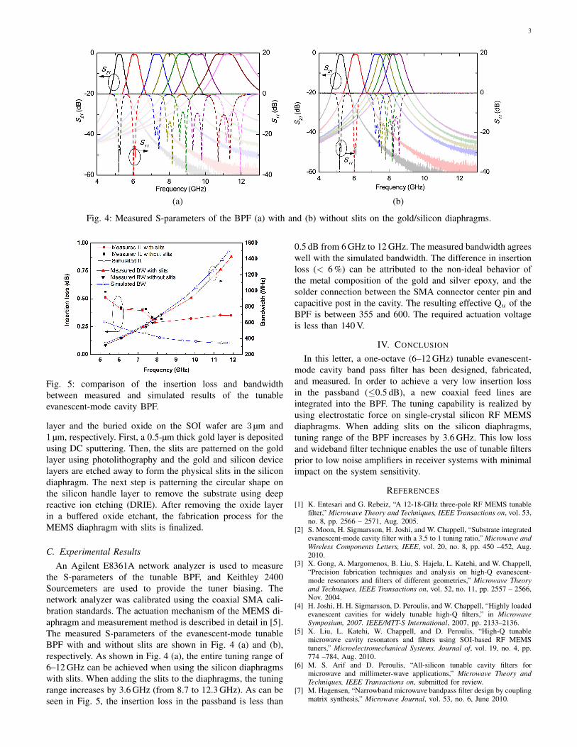
(a) (b)
Fig. 4: Measured S-parameters of the BPF (a) with and (b) without slits on the gold/silicon diaphragms.
Fig. 5: comparison of the insertion loss and bandwidthbetween measured and simulated results of the tunableevanescent-mode cavity BPF.
layer and the buried oxide on the SOI wafer are 3 µm and1 µm, respectively. First, a 0.5-µm thick gold layer is depositedusing DC sputtering. Then, the slits are patterned on the goldlayer using photolithography and the gold and silicon devicelayers are etched away to form the physical slits in the silicondiaphragm. The next step is patterning the circular shape onthe silicon handle layer to remove the substrate using deepreactive ion etching (DRIE). After removing the oxide layerin a buffered oxide etchant, the fabrication process for theMEMS diaphragm with slits is finalized.
C. Experimental Results
An Agilent E8361A network analyzer is used to measurethe S-parameters of the tunable BPF, and Keithley 2400Sourcemeters are used to provide the tuner biasing. Thenetwork analyzer was calibrated using the coaxial SMA cali-bration standards. The actuation mechanism of the MEMS di-aphragm and measurement method is described in detail in [5].The measured S-parameters of the evanescent-mode tunableBPF with and without slits are shown in Fig. 4 (a) and (b),respectively. As shown in Fig. 4 (a), the entire tuning range of6–12 GHz can be achieved when using the silicon diaphragmswith slits. When adding the slits to the diaphragms, the tuningrange increases by 3.6 GHz (from 8.7 to 12.3 GHz). As can beseen in Fig. 5, the insertion loss in the passband is less than
0.5 dB from 6 GHz to 12 GHz. The measured bandwidth agreeswell with the simulated bandwidth. The difference in insertionloss (< 6 %) can be attributed to the non-ideal behavior ofthe metal composition of the gold and silver epoxy, and thesolder connection between the SMA connector center pin andcapacitive post in the cavity. The resulting effective Qu of theBPF is between 355 and 600. The required actuation voltageis less than 140 V.
IV. CONCLUSION
In this letter, a one-octave (6–12 GHz) tunable evanescent-mode cavity band pass filter has been designed, fabricated,and measured. In order to achieve a very low insertion lossin the passband (≤0.5 dB), a new coaxial feed lines areintegrated into the BPF. The tuning capability is realized byusing electrostatic force on single-crystal silicon RF MEMSdiaphragms. When adding slits on the silicon diaphragms,tuning range of the BPF increases by 3.6 GHz. This low lossand wideband filter technique enables the use of tunable filtersprior to low noise amplifiers in receiver systems with minimalimpact on the system sensitivity.
REFERENCES
[1] K. Entesari and G. Rebeiz, “A 12-18-GHz three-pole RF MEMS tunablefilter,” Microwave Theory and Techniques, IEEE Transactions on, vol. 53,no. 8, pp. 2566 – 2571, Aug. 2005.
[2] S. Moon, H. Sigmarsson, H. Joshi, and W. Chappell, “Substrate integratedevanescent-mode cavity filter with a 3.5 to 1 tuning ratio,” Microwave andWireless Components Letters, IEEE, vol. 20, no. 8, pp. 450 –452, Aug.2010.
[3] X. Gong, A. Margomenos, B. Liu, S. Hajela, L. Katehi, and W. Chappell,“Precision fabrication techniques and analysis on high-Q evanescent-mode resonators and filters of different geometries,” Microwave Theoryand Techniques, IEEE Transactions on, vol. 52, no. 11, pp. 2557 – 2566,Nov. 2004.
[4] H. Joshi, H. H. Sigmarsson, D. Peroulis, and W. Chappell, “Highly loadedevanescent cavities for widely tunable high-Q filters,” in MicrowaveSymposium, 2007. IEEE/MTT-S International, 2007, pp. 2133–2136.
[5] X. Liu, L. Katehi, W. Chappell, and D. Peroulis, “High-Q tunablemicrowave cavity resonators and filters using SOI-based RF MEMStuners,” Microelectromechanical Systems, Journal of, vol. 19, no. 4, pp.774 –784, Aug. 2010.
[6] M. S. Arif and D. Peroulis, “All-silicon tunable cavity filters formicrowave and millimeter-wave applications,” Microwave Theory andTechniques, IEEE Transactions on, submitted for review.
[7] M. Hagensen, “Narrowband microwave bandpass filter design by couplingmatrix synthesis,” Microwave Journal, vol. 53, no. 6, June 2010.