Embed Size (px)
Citation preview
Behavior Research Methods & Instrumentation1977, Vol. 9 (3),253-255
Development of an inexpensive remote radiocontrol system for slide projection
JAMESH.K. YOODepartment ofBioengineering, University ofTexas, Health Science Center at San Antonio, San Antonio,
Texas 78284
An inexpensive remote radio control system for slide projection has been developed. It consists of anelectronic receiver/decoder designed for attachment to commercially available slide projectors and aself-contained, portable FM transmitter with a foldable (collapsible) antenna/pointer. The system allowsremote lens focusing (forward and backward) and slide change (forward and reverse) to be accomplishedover a lOO-it range. It offers desirable freedom of movement to the lecturer or behavioral researcher, byeliminating locational restraints imposed by the extension cord.
Slide projectors are used by thousands of orators andresearchers throughout the world It is often desirableto control slide projectors remotely without the restraintof extension cords. This is not only true for thosepublic speakers and presentors on the podium, butalso for many of the behavioral researchers (Humphries,Phoebus, & Globus, 1974; Mackay, 1970). The systemdescribed here will free the speaker or operator fromlocational restraints and allow him to move freely orto perform necessary covert operations remotely.
An electronic receiver to be attached to commerciallyavailable slide projectors and a portable FM transmitterwith a foldable pointer/antenna have been designed andconstructed. The remote radio control system for theslide projector can transmit the control signals morethan 100 ft. It has four functions: lens focusing, forwardand backward, and slide change, forward and reverse.This paper describes the electronic circuit aspects of theinexpensive remote radio control system.
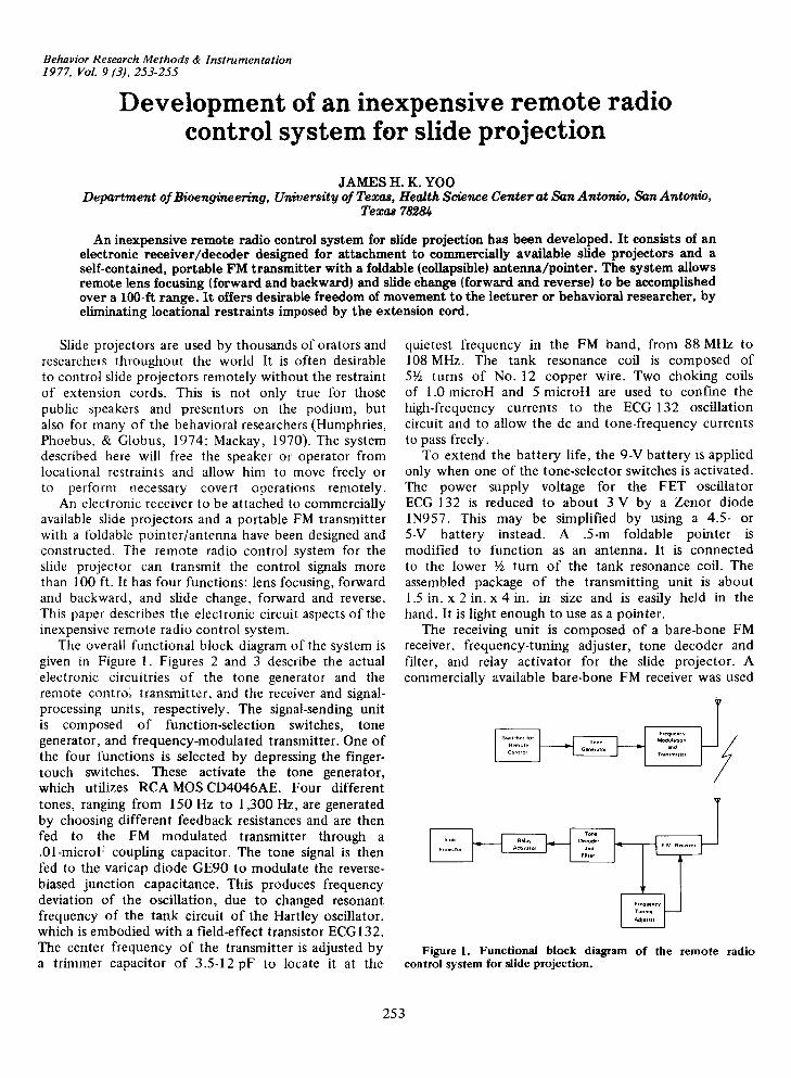
The overall functional block diagram of the system isgiven in Figure I. Figures 2 and 3 describe the actualelectronic circuitries of the tone generator and theremote control transmitter, and the receiver and signalprocessing units, respectively. The signal-sending unitis composed of function-selection switches, tonegenerator, and frequency-modulated transmitter. One ofthe four functions is selected by depressing the fingertouch switches. These activate the tone generator,which utilizes RCA MOS CD4046AE. Four differenttones, ranging from 150 Hz to 1,300 Hz, are generatedby choosing different feedback resistances and are thenfed to the FM modulated transmitter through a.01-microF coupling capacitor. The tone signal is thenfed to the varicap diode GE90 to modulate the reversebiased junction capacitance. This produces frequencydeviation of the oscillation, due to changed resonantfrequency of the tank circuit of the Hartley oscillator,which is embodied with a field-effect transistor ECG132.The center frequency of the transmitter is adjusted bya trimmer capacitor of 3.5-12 pF to locate it at the
quietest frequency in the FM band, from 88 MHz to108 MHz. The tank resonance coil is composed ofS~ turns of No. 12 copper wire. Two choking coilsof 1.0 microH and 5 microH are used to confine thehigh-frequency currents to the ECG 132 oscillationcircuit and to allow the de and tone-frequency currentsto pass freely.
To extend the battery life, the 9-V battery is appliedonly when one of the tone-selector switches is activated.The power supply voltage for the FET oscillatorECG 132 is reduced to about 3 V by a Zenor diodeIN957. This may be simplified by using a 4.5- orS-V battery instead. A .S-m foldable pointer ismodified to function as an antenna. It is connectedto the lower ~ turn of the tank resonance coil. Theassembled package of the transmitting unit is about1.5 in. x 2 in. x 4 in. in size and is easily held in thehand. It is light enough to use as a pointer.
The receiving unit is composed of a bare-bone FMreceiver, frequency-tuning adjuster, tone decoder andfilter, and relay activator for the slide projector. Acommercially available bare-bone FM receiver was used
Figure I. Functional block diagram of the remote radiocontrol system for slide projection.
253
254 YOO
IN9673.IK
II 1.0jIH
10K
51
12K 15K ',18... ...
22K
22K
,... ... ...
6.8pF
rGE90
,.
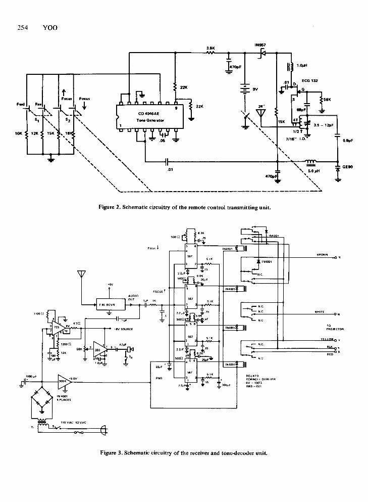
Figure 2. Schematic circuitry of the remote control transmitting unit.
BROWN
FOCUS t
5.1K
WHITEW
.1J.1F NC
TO+8V SOURCE 1N400 PROJECTOR
5.1K
47J.1F N.CBL'I 6'T •
ORRED
soon NC
'2#' •~ IN4001
5.1K RELAYS+5.0V 'WD CORNEllOUBlIER
+" 6V - lOOn~300"' (683 - 6Vl
Figure 3. Schematic circuitry of the receiver and tone-decoder unit.
for the study and cost about $7.50. A l-ft rod antennapicks up the FM control signal. The audio outputfrom the receiver is fed to the tone-decoder unit,composed of four parallel phase-locked loop tonedecoders (Gardner, 1966). NE567 tone-decoder phaselocked loop circuits separate the received control signalsand activate the appropriate relay. lN400l diodes areconnected in parallel with the relay coils to activatethem selectively only one at a time. The relays aredouble-pole double-throw types made by the CornellDublier Company. They are activated selectively oneat a time by 5-V de supplied by Pin 6 of NE567. Theproper circuit connections to meet Kodak 2 by 2 slideprojectors are shown in Figure 3. The modified slideprojector extension cord and male sockets are pluggedinto the slide projectors as usual.
An additional feature of the system is the frequencytuning adjuster, composed of LM380 and a minispeaker.The audio output from the FM receiver is fed to LM380to accomplish further amplification for audible sound.The receiver tuning is achieved with maximum speakersound and proper activation of the slide-projectoractivation switches in the chosen FM band. Theunregulated power supply is provided by a four-diodebridge rectifier. A +5-V de is obtained at the outputof the voltage regulator LM305K. The regulated +8-V deis provided by another voltage regulator, LM723, andthe associated low-pass filter. This may be easilyreplaced by different types of regulators, such asLM320-8T. The components for construction of thereceiving unit are commercially available off-shelf
REMOTE RADIO CONTROL SYSTEM 255
components. They may cost less than $25. The sizeof the assembled prototype is about 6 in. x 8 in. x 8 in.It is portable and has a leather carrying handle on topof the unit.
Installation and field operation of the remote radiocontrol system for slide projection are simple. Thesystem is nondirectional in its 100-ft coverage.Operational range may be extended farther. Since theoutput is smaller than 50 mW, it may not need to meetany stringent FCC license requirements. The flexibilityof choosing the proper FM broadcasting frequencyfor the quietest band in the region is a very importantaspect of the system. Interference seldom occurredduring the extensive testing operations. Accurate tonegeneration by aMOS IC and reliable decoding by phaselocked loop tone-decoder circuitry, along with the lowcost, may offer very useful applications in manydisciplines of behavioral research.
REFERENCES
GARDNER, F. M., Phase-lock techniques. New York: JohnWiley, 1966.
HUMPHRIES, J., PHOEBUS, E., & GLOBUS, G. A micropowermultichannel biotelemetry system. Psychophysiology, 1974,11, 382-387.
MACKAY, R. S. Biomedical telemetry. New York: John Wiley,1970.
(Received for publication September 24, 1976;accepted October 20, 1976.)