Embed Size (px)
Citation preview
1
Development of Friction Moderating System to Improve Wheel/Rail Interface in Sharp Curves
1S. Fukagai, 1T. Ban, 1A. Namura, 1M. Ishida, 1*M. Ogata, 1*F. Aoki, 2T. Arai Railway Technical Research Institute, Tokyo, Japan1;
Tokyu Corporation, Tokyo, Japan2 (Returned to East Japan Railway Company)*
Abstract
Lubrication on sharp curves has been commonly adopted as a method of reducing friction between the wheel flange and rail gauge face to minimize wear and energy consumption. Additionally, lubrication between the running surface of the low-rail and the wheel tread has recently been recognized as a significant factor in reducing the likelihood of low-rail corrugation, squealing noise and rail gauge face wear. This paper describes a friction-moderating system (FRIMOS) for the interface between the top of the low-rail and the wheel tread, consisting of a solid lubricant known as a friction moderator and a jetting device installed on the vehicle to apply the moderator to the wheel/rail interface.
1. Introduction
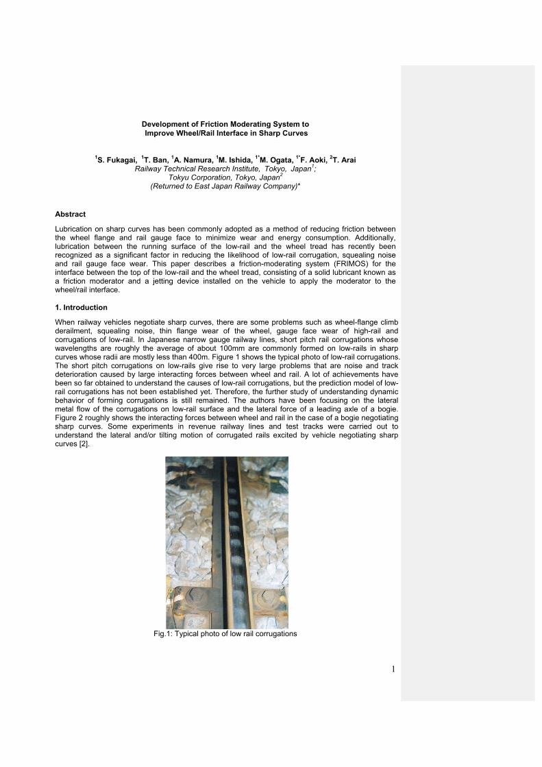
When railway vehicles negotiate sharp curves, there are some problems such as wheel-flange climb derailment, squealing noise, thin flange wear of the wheel, gauge face wear of high-rail and corrugations of low-rail. In Japanese narrow gauge railway lines, short pitch rail corrugations whose wavelengths are roughly the average of about 100mm are commonly formed on low-rails in sharp curves whose radii are mostly less than 400m. Figure 1 shows the typical photo of low-rail corrugations. The short pitch corrugations on low-rails give rise to very large problems that are noise and track deterioration caused by large interacting forces between wheel and rail. A lot of achievements have been so far obtained to understand the causes of low-rail corrugations, but the prediction model of low-rail corrugations has not been established yet. Therefore, the further study of understanding dynamic behavior of forming corrugations is still remained. The authors have been focusing on the lateral metal flow of the corrugations on low-rail surface and the lateral force of a leading axle of a bogie. Figure 2 roughly shows the interacting forces between wheel and rail in the case of a bogie negotiating sharp curves. Some experiments in revenue railway lines and test tracks were carried out to understand the lateral and/or tilting motion of corrugated rails excited by vehicle negotiating sharp curves [2].
Fig.1: Typical photo of low rail corrugations
2
Attack angle
Lateral
Longitudinalcreepage force
creepage force
Running direction
Wheel flangereaction force
Fig.2: Creep forces interacting between wheel and rail in a bogie
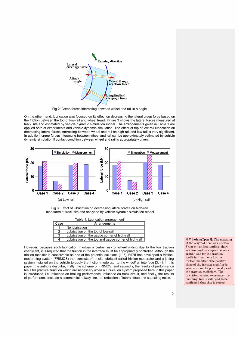
On the other hand, lubrication was focused on its effect on decreasing the lateral creep force based on the friction between the top of low-rail and wheel tread. Figure 3 shows the lateral forces measured at track site and estimated by vehicle dynamic simulation model. The arrangements given in Table 1 are applied both of experiments and vehicle dynamic simulation. The effect of top of low-rail lubrication on decreasing lateral forces interacting between wheel and rail on high-rail and low-rail is very significant. In addition, creep forces interacting between wheel and rail can be approximately estimated by vehicle dynamic simulation if contact condition between wheel and rail is appropriately given.
Fig.3: Effect of lubrication on decreasing lateral forces on high-rail
measured at track site and analysed by vehicle dynamic simulation model
Table 1: Lubrication arrangement Case Arrangements
1 No lubrication 2 Lubrication on the top of low-rail 3 Lubrication on the gauge corner of high-rail 4 Lubrication on the top and gauge corner of high-rail
However, because such lubrication involves a certain risk of wheel sliding due to the low traction coefficient, it is required that the friction in the interface must be appropriately controlled. Although the friction modifier is conceivable as one of the potential solutions [1, 6], RTRI has developed a friction-moderating system (FRIMOS) that consists of a solid lubricant called friction moderator and a jetting system installed on the vehicle to apply the friction moderator to the wheel/rail interface [3, 4]. In this paper, the authors describe, firstly, the scheme of FRIMOS, and secondly, the results of performance tests for practical function which are necessary when a lubrication system proposed here in this paper is introduced, i.e. influence on braking performance, influence on track circuit, and finally, the results of performance tests on a commercial railway line, i.e. reduction of lateral force and squealing noise.
(a) Low rail (b) High rail
0
10
20
30
Case 1 Case 2 Case 3 Case 4
Simulation Measurement
Late
ral f
orce
(kN
)
0
10
20
30
Case 1 Case 2 Case 3 Case 4
Simulation Measurement
Late
ral f
orce
(kN
)
0
10
20
30
Case 1 Case 2 Case 3 Case 4
Simulation Measurement
Late
ral f
orce
(kN
)
0
10
20
30
Case 1 Case 2 Case 3 Case 4
Simulation Measurement
Late
ral f
orce
(kN
)
0
10
20
30
Case 1 Case 2 Case 3 Case 4
Simulation Measurement
Late
ral f
orce
(kN
)
0
10
20
30
Case 1 Case 2 Case 3 Case 4
Simulation Measurement
Late
ral f
orce
(kN
)
메모 [adam@pge1]: The meaning of the original here was unclear. From my understanding: there are two positive slopes (i.e. on a graph), one for the traction coefficient, and one for the friction modifier. The positive slope of the friction modifier is greater than the positive slope of the traction coefficient. The rewritten version expresses this meaning, but it will need to be confirmed that this is correct.
3
2. Friction-moderating System
2. 1 Friction Moderator
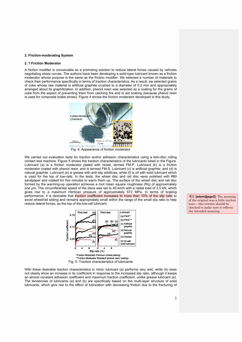
A friction modifier is conceivable as a promising solution to reduce lateral forces caused by vehicles negotiating sharp curves. The authors have been developing a solid-type lubricant known as a friction moderator whose purpose is the same as the friction modifier. We selected a number of materials to check their performance specifically in terms of traction characteristics. As a result, we selected grains of coke whose raw material is artificial graphite crushed to a diameter of 0.2 mm and appropriately arranged about its graphitization. In addition, phenol resin was selected as a coating for the grains of coke from the aspect of preventing them from catching fire and to aid braking (because phenol resin is used for composite brake shoes). Figure 4 shows the friction moderator developed in this study.
Fig. 4: Appearance of friction moderator
We carried out evaluation tests for traction and/or adhesion characteristics using a twin-disc rolling contact test machine. Figure 5 shows the traction characteristics of the lubricants listed in the Figure. Lubricant (a) is a friction moderator plated with nickel, termed FM-P. Lubricant (b) is a friction moderator coated with phenol resin, and is termed FM-S. Lubricant (c) is artificial graphite, and (d) is natural graphite. Lubricant (e) is grease with anti-slip additives, while (f) is oil with solid lubricant which is used for the top of low-rails. In the tests, the wheel disc and rail disc were polished with #80 sandpaper and rotated for five minutes to warm them up. The surface of the wheel disc and rail disc formed by the warming-up operation achieves a root mean square roughness (Rq) of approximately one μm. The circumferential speed of the discs was set to 40 km/h with a radial load of 3.5 kN, which gives rise to a maximum Hertzian pressure of approximately 672 MPa. In terms of braking performance, it is desirable that traction coefficient increases to more than 10% of the slip ratio to avoid wheel/rail sliding and remains appropriately small within the range of the small slip ratio to help reduce lateral forces, as the top of the low-rail lubricant.
0 84 84
0.15
0.10
0.05
Slip ratio (%)
Trac
tion
coef
ficie
nt
(a)
(b)
(c)
(d)
(f)
(e) (d)
(f)
(e)
First test Third test
(a) (b) (c)
Lubricant
(a) FM-P *(b) FM-S **
(c) Artificialgraphite
(d) Naturalgraphite
(e) Grease
(f) Oil with solid lubricant
*Friction Moderator Premium (nickel plating)**Friction Moderator Standard (phenol resin coating)
00 84 84
0.15
0.10
0.05
Slip ratio (%)
Trac
tion
coef
ficie
nt
(a)
(b)
(c)
(d)
(f)
(e) (d)
(f)
(e)
First test Third test
(a) (b) (c)
Lubricant
(a) FM-P *(b) FM-S **
(c) Artificialgraphite
(d) Naturalgraphite
(e) Grease
(f) Oil with solid lubricant
*Friction Moderator Premium (nickel plating)**Friction Moderator Standard (phenol resin coating)
0
Fig. 5: Traction characteristics of lubricants
With these desirable traction characteristics in mind, lubricant (a) performs very well, while (b) does not clearly show an increase in its coefficient in response to the increased slip ratio, although it keeps an almost constant adhesion coefficient and maximum traction coefficient, unlike grease lubricant (e). The tendencies of lubricants (a) and (b) are specifically based on the multi-layer structure of solid lubricants, which give rise to the effect of lubrication with decreasing friction due to the fracturing of
메모 [adam@pge2]: The meaning of the original was a little unclear here – this rewrite should be checked to make sure it reflects the intended meaning.
4
their structure and the consequent sliding between two layers. Carbon-based lubricants (a) to (d) thus do not show a decrease in the traction coefficient with a large slip ratio. In addition, the figure shows that lubricants (a) and (b), whose graphitization is lower than that of the artificial-graphite-based (c), display a traction coefficient larger than that of lubricant (c) in the first test (i.e. the first measurement after lubricant was applied to the interface of the wheel/rail discs). However, in the third test (i.e. the third measurement without the addition of lubricant to the interface of the wheel/rail discs), the tendencies of lubricants (a) and (b) are almost the same as that of lubricant (c). This result may suggest that the coating materials of lubricants (a) and (b) have some contribution on the positive or negative slope of the traction coefficient.
2. 2 Jetting system for the friction moderator
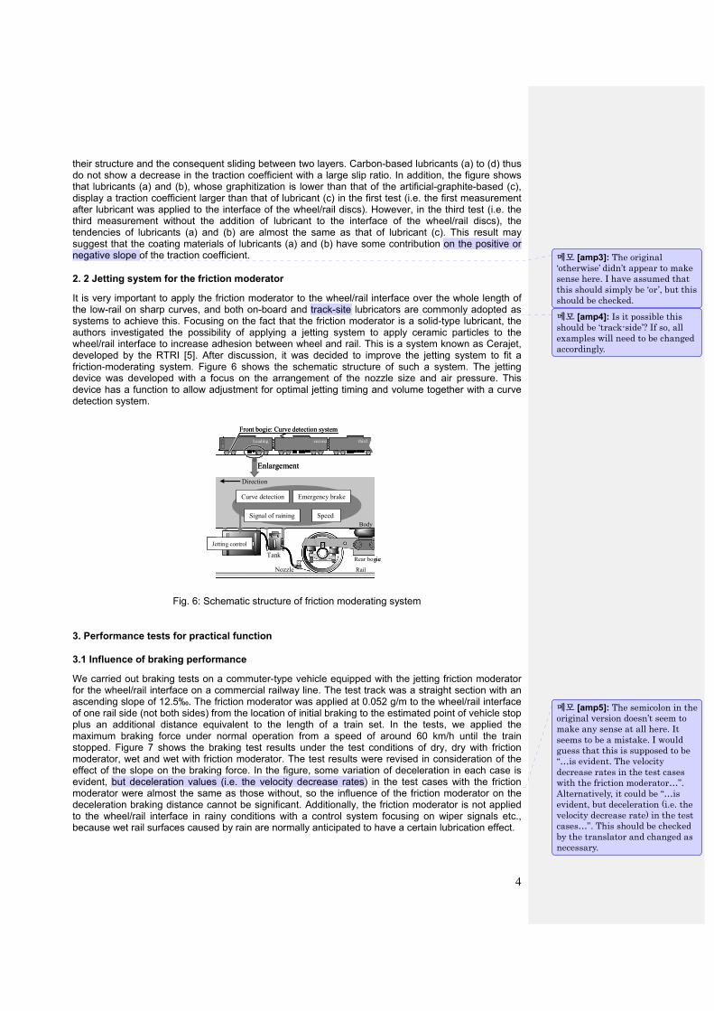
It is very important to apply the friction moderator to the wheel/rail interface over the whole length of the low-rail on sharp curves, and both on-board and track-site lubricators are commonly adopted as systems to achieve this. Focusing on the fact that the friction moderator is a solid-type lubricant, the authors investigated the possibility of applying a jetting system to apply ceramic particles to the wheel/rail interface to increase adhesion between wheel and rail. This is a system known as Cerajet, developed by the RTRI [5]. After discussion, it was decided to improve the jetting system to fit a friction-moderating system. Figure 6 shows the schematic structure of such a system. The jetting device was developed with a focus on the arrangement of the nozzle size and air pressure. This device has a function to allow adjustment for optimal jetting timing and volume together with a curve detection system.
摩擦緩和材噴射制御装置Jetting control
Tank
Nozzle
Direction
Signal of raining Speed
Emergency brakeCurve detection
Rear bogie
Body
Rail
Enlargement
Front bogie: Curve detection systemLeading second third
摩擦緩和材噴射制御装置Jetting control
Tank
Nozzle
Direction
Signal of raining Speed
Emergency brakeCurve detection
Rear bogie
Body
Rail
Enlargement
Front bogie: Curve detection systemLeading second third
Fig. 6: Schematic structure of friction moderating system
3. Performance tests for practical function
3.1 Influence of braking performance
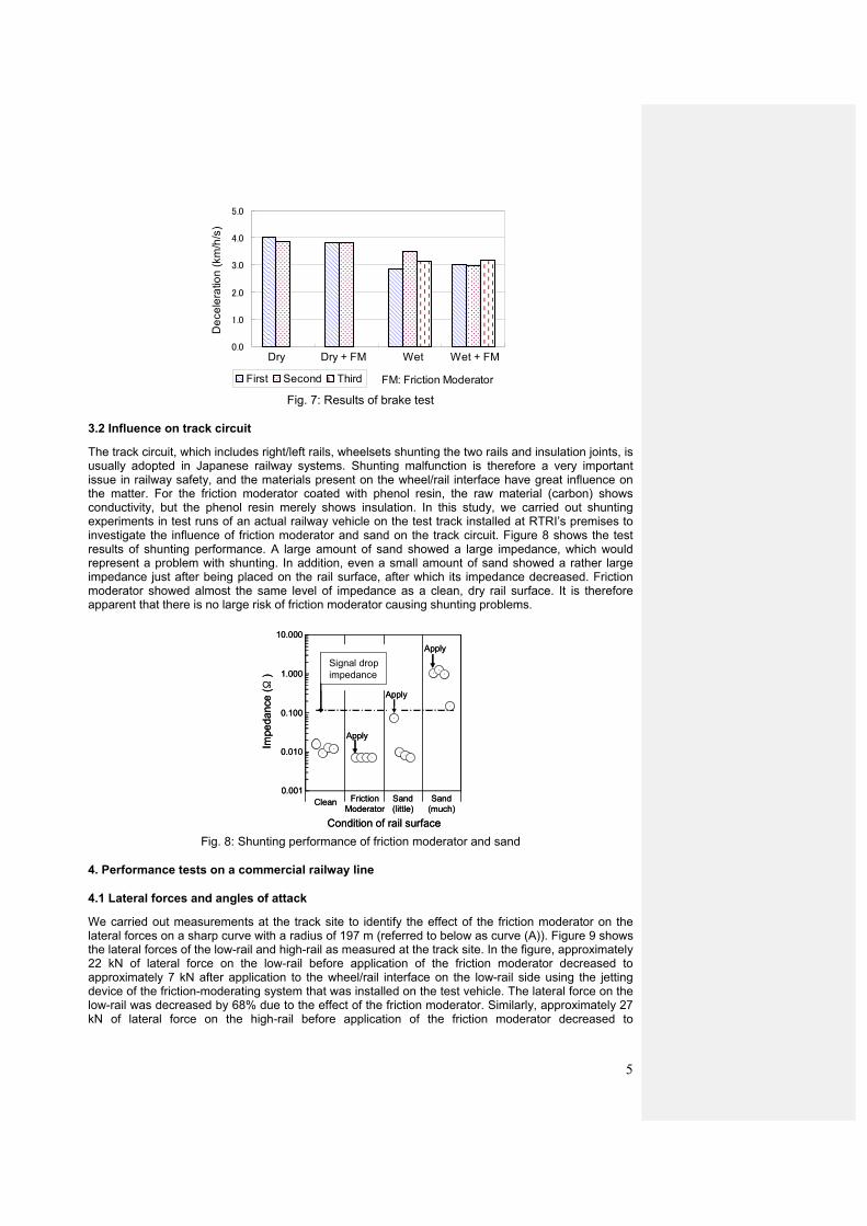
We carried out braking tests on a commuter-type vehicle equipped with the jetting friction moderator for the wheel/rail interface on a commercial railway line. The test track was a straight section with an ascending slope of 12.5‰. The friction moderator was applied at 0.052 g/m to the wheel/rail interface of one rail side (not both sides) from the location of initial braking to the estimated point of vehicle stop plus an additional distance equivalent to the length of a train set. In the tests, we applied the maximum braking force under normal operation from a speed of around 60 km/h until the train stopped. Figure 7 shows the braking test results under the test conditions of dry, dry with friction moderator, wet and wet with friction moderator. The test results were revised in consideration of the effect of the slope on the braking force. In the figure, some variation of deceleration in each case is evident, but deceleration values (i.e. the velocity decrease rates) in the test cases with the friction moderator were almost the same as those without, so the influence of the friction moderator on the deceleration braking distance cannot be significant. Additionally, the friction moderator is not applied to the wheel/rail interface in rainy conditions with a control system focusing on wiper signals etc., because wet rail surfaces caused by rain are normally anticipated to have a certain lubrication effect.
메모 [amp3]: The original ‘otherwise’ didn’t appear to make sense here. I have assumed that this should simply be ‘or’, but this should be checked.
메모 [amp4]: Is it possible this should be ‘track-side’? If so, all examples will need to be changed accordingly.
메모 [amp5]: The semicolon in the original version doesn’t seem to make any sense at all here. It seems to be a mistake. I would guess that this is supposed to be “…is evident. The velocity decrease rates in the test cases with the friction moderator…”. Alternatively, it could be “…is evident, but deceleration (i.e. the velocity decrease rate) in the test cases…”. This should be checked by the translator and changed as necessary.
5
0.0
1.0
2.0
3.0
4.0
5.0D
ecel
erat
ion
(km
/h/s
)
First Second Third FM: Friction Moderator
Dry Dry + FM Wet + FMWet
Fig. 7: Results of brake test
3.2 Influence on track circuit
The track circuit, which includes right/left rails, wheelsets shunting the two rails and insulation joints, is usually adopted in Japanese railway systems. Shunting malfunction is therefore a very important issue in railway safety, and the materials present on the wheel/rail interface have great influence on the matter. For the friction moderator coated with phenol resin, the raw material (carbon) shows conductivity, but the phenol resin merely shows insulation. In this study, we carried out shunting experiments in test runs of an actual railway vehicle on the test track installed at RTRI’s premises to investigate the influence of friction moderator and sand on the track circuit. Figure 8 shows the test results of shunting performance. A large amount of sand showed a large impedance, which would represent a problem with shunting. In addition, even a small amount of sand showed a rather large impedance just after being placed on the rail surface, after which its impedance decreased. Friction moderator showed almost the same level of impedance as a clean, dry rail surface. It is therefore apparent that there is no large risk of friction moderator causing shunting problems.
10.000
1.000
0.010
Condition of rail surface
Impe
danc
e (Ω
)
0.100
0.001
Signal dropimpedance
Apply
Apply
Apply
Clean FrictionModerator
Sand(little)
Sand(much)
10.000
1.000
0.010
Condition of rail surface
Impe
danc
e (Ω
)
0.100
0.001
Signal dropimpedance
Apply
Apply
Apply
Clean FrictionModerator
Sand(little)
Sand(much)
Fig. 8: Shunting performance of friction moderator and sand
4. Performance tests on a commercial railway line
4.1 Lateral forces and angles of attack
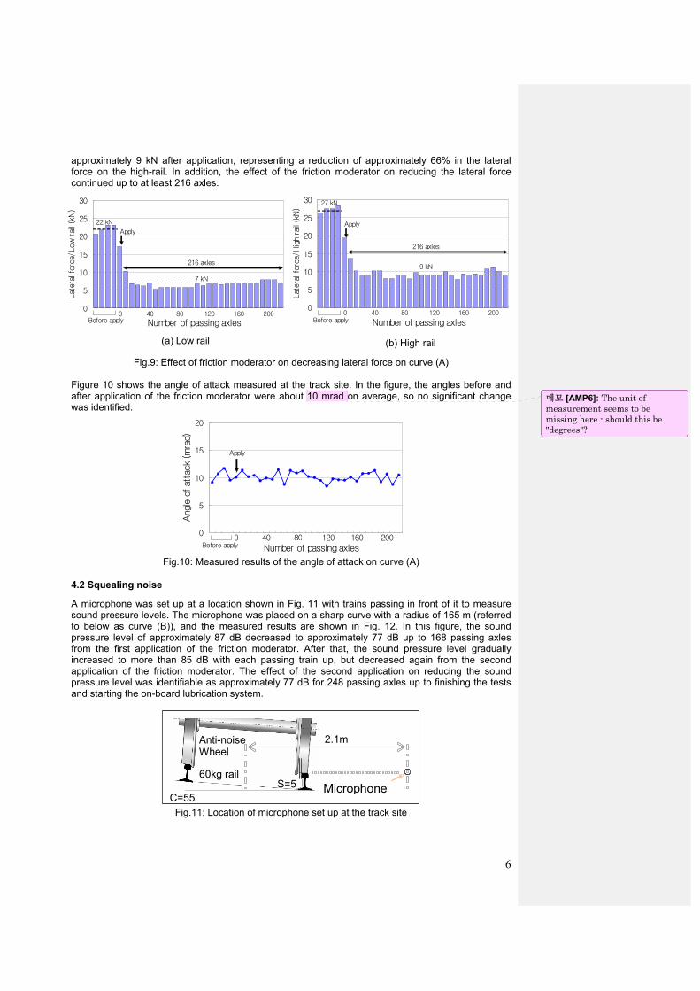
We carried out measurements at the track site to identify the effect of the friction moderator on the lateral forces on a sharp curve with a radius of 197 m (referred to below as curve (A)). Figure 9 shows the lateral forces of the low-rail and high-rail as measured at the track site. In the figure, approximately 22 kN of lateral force on the low-rail before application of the friction moderator decreased to approximately 7 kN after application to the wheel/rail interface on the low-rail side using the jetting device of the friction-moderating system that was installed on the test vehicle. The lateral force on the low-rail was decreased by 68% due to the effect of the friction moderator. Similarly, approximately 27 kN of lateral force on the high-rail before application of the friction moderator decreased to
6
approximately 9 kN after application, representing a reduction of approximately 66% in the lateral force on the high-rail. In addition, the effect of the friction moderator on reducing the lateral force continued up to at least 216 axles.
Fig.9: Effect of friction moderator on decreasing lateral force on curve (A) Figure 10 shows the angle of attack measured at the track site. In the figure, the angles before and after application of the friction moderator were about 10 mrad on average, so no significant change was identified.
0
5
10
15
20
8 48 88 128 168 208
Angl
e o
f at
tack
(mra
d)
Number of passing axlesBefore apply0 40 80 120 160 200
Apply
Fig.10: Measured results of the angle of attack on curve (A)
4.2 Squealing noise
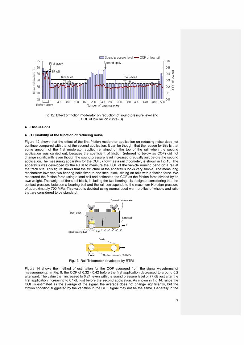
A microphone was set up at a location shown in Fig. 11 with trains passing in front of it to measure sound pressure levels. The microphone was placed on a sharp curve with a radius of 165 m (referred to below as curve (B)), and the measured results are shown in Fig. 12. In this figure, the sound pressure level of approximately 87 dB decreased to approximately 77 dB up to 168 passing axles from the first application of the friction moderator. After that, the sound pressure level gradually increased to more than 85 dB with each passing train up, but decreased again from the second application of the friction moderator. The effect of the second application on reducing the sound pressure level was identifiable as approximately 77 dB for 248 passing axles up to finishing the tests and starting the on-board lubrication system.
C=55 S=5
2.1m
Microphone
Anti-noise Wheel
60kg rail
Fig.11: Location of microphone set up at the track site
0
5
10
15
20
25
30
8 48 88 128 168 208
Lat
eral
for
ce/L
ow rai
l (k
N)
0 40 80 120 160 200Before apply Number of passing axles
Apply
216 axles
22 kN
7 kN
0
5
10
15
20
25
30
8 48 88 128 168 208
Lat
eral
for
ce/H
igh
rail
(kN)
0 40 80 120 160 200
Number of passing axlesBefore apply
Apply
27 kN
9 kN
216 axles
(a) Low rail (b) High rail
메모 [AMP6]: The unit of measurement seems to be missing here - should this be "degrees"?
7
65
70
75
80
85
90
95
Number of passing axles
Sound
press
ure
leve
l(dB
)
0.0
0.1
0.2
0.3
0.4
0.5
0.6
CO
F o
f lo
w r
ail
Sound pressure level COF of low rail
Second apply
Before apply
168 axles 248 axles
First apply
77 dB 77 dB
87 dB
0 40 80 120 160 240200 280 320 360 400 440 480 520
Fig.12: Effect of friction moderator on reduction of sound pressure level and
COF of low rail on curve (B)
4.3 Discussions
4.3.1 Durability of the function of reducing noise
Figure 12 shows that the effect of the first friction moderator application on reducing noise does not continue compared with that of the second application. It can be thought that the reason for this is that some amount of the first moderator applied remained on the top of the rail when the second application was carried out, because the coefficient of friction (referred to below as COF) did not change significantly even though the sound pressure level increased gradually just before the second application.The measuring apparatus for the COF, known as a rail tribometer, is shown in Fig.13. The apparatus was developed by the RTRI to measure the COF of the vehicle running band on a rail at the track site. This figure shows that the structure of the apparatus looks very simple. The measuring mechanism involves two bearing balls fixed to one steel block sliding on rails with a friction force. We measured the friction force using a load cell and estimated the COF as the friction force divided by its own weight. The weight of the steel block, including the two bearings, is designed considering that the contact pressure between a bearing ball and the rail corresponds to the maximum Hertzian pressure of approximately 700 MPa. This value is decided using normal used worn profiles of wheels and rails that are considered to be standard.
Dynamic strain meter
F
Load cell
Steel block
Steel bearing ball Rail
Guide
Contact pressure 686 MPa
Dynamic strain meter
F
Load cell
Steel block
Steel bearing ball Rail
Guide
Contact pressure 686 MPa
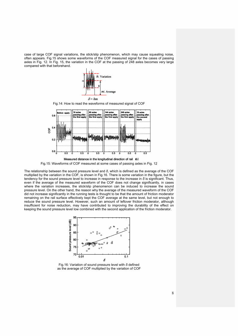
Fig.13: Rail Tribometer developed by RTRI Figure 14 shows the method of estimation for the COF averaged from the signal waveforms of measurements. In Fig. 9, the COF of 0.32 - 0.42 before the first application decreased to around 0.2 afterward. The value then increased to 0.24, even with the sound pressure level of 77 dB just after the first application increasing to 87 dB just before the second application. As shown in Fig.14, since the COF is estimated as the average of the signal, the average does not change significantly, but the friction condition suggested by the variation in the COF signal may not be the same. Generally in the
8
case of large COF signal variations, the stick/slip phenomenon, which may cause squealing noise, often appears. Fig.15 shows some waveforms of the COF measured signal for the cases of passing axles in Fig. 12. In Fig. 15, the variation in the COF at the passing of 248 axles becomes very large compared with that beforehand.
h
δ = hm
h: Variation
m: Average
m
h
δ = hm
h: Variation
m: Average
m
Fig.14: How to read the waveforms of measured signal of COF
0 0.5 0 0.5 0 0.5 0 0.5 0 0.5 0 0.50.0
0.2
0.4
0.6
CO
F
Measured distance in the longitudinal direction of rail (m)
Before apply 16 axles passing after the first apply
80 axles passing after the first apply
144 axles passing after the first apply
248 axles passing after the first apply
16 axles passing after the second apply
0 0.5 0 0.5 0 0.5 0 0.5 0 0.5 0 0.50.0
0.2
0.4
0.6
0.0
0.2
0.4
0.6
CO
F
Measured distance in the longitudinal direction of rail (m)
Before apply 16 axles passing after the first apply
80 axles passing after the first apply
144 axles passing after the first apply
248 axles passing after the first apply
16 axles passing after the second apply
Fig.15: Waveforms of COF measured at some cases of passing axles in Fig. 12
The relationship between the sound pressure level and δ, which is defined as the average of the COF multiplied by the variation in the COF, is shown in Fig.16. There is some variation in the figure, but the tendency for the sound pressure level to increase in response to the increase in δ is significant. Thus, even if the average of the measured waveform of the COF does not change significantly, in cases where the variation increases, the stick/slip phenomenon can be induced to increase the sound pressure level. On the other hand, the reason why the average of the measured waveform of the COF did not increase significantly in the running tests is thought to be that the amount of friction moderator remaining on the rail surface effectively kept the COF average at the same level, but not enough to reduce the sound pressure level. However, such an amount of leftover friction moderator, although insufficient for noise reduction, may have contributed to improving the durability of the effect on keeping the sound pressure level low combined with the second application of the friction moderator.
0.01 0.170
75
80
85
90
95
δ
Sou
nd p
ress
ure
leve
l (dB
)
0.01 0.170
75
80
85
90
95
δ
Sou
nd p
ress
ure
leve
l (dB
)
Fig.16: Variation of sound pressure level with δ defined
as the average of COF multiplied by the variation of COF
9
4.3.2 Effect of the friction moderator on the reduction of noise caused by rail corrugation
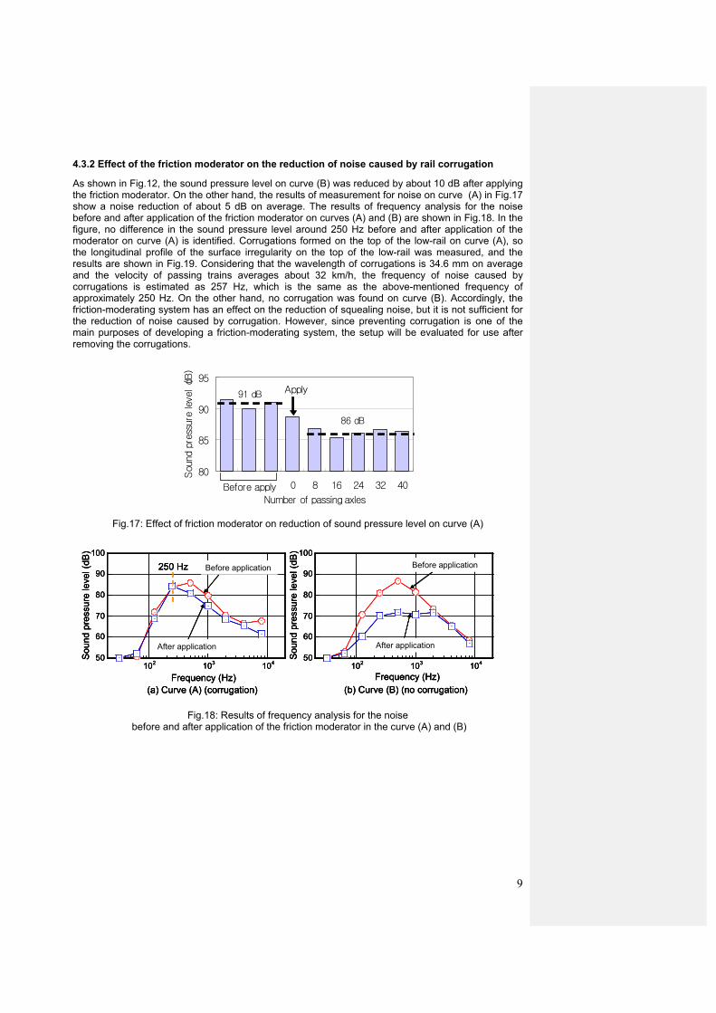
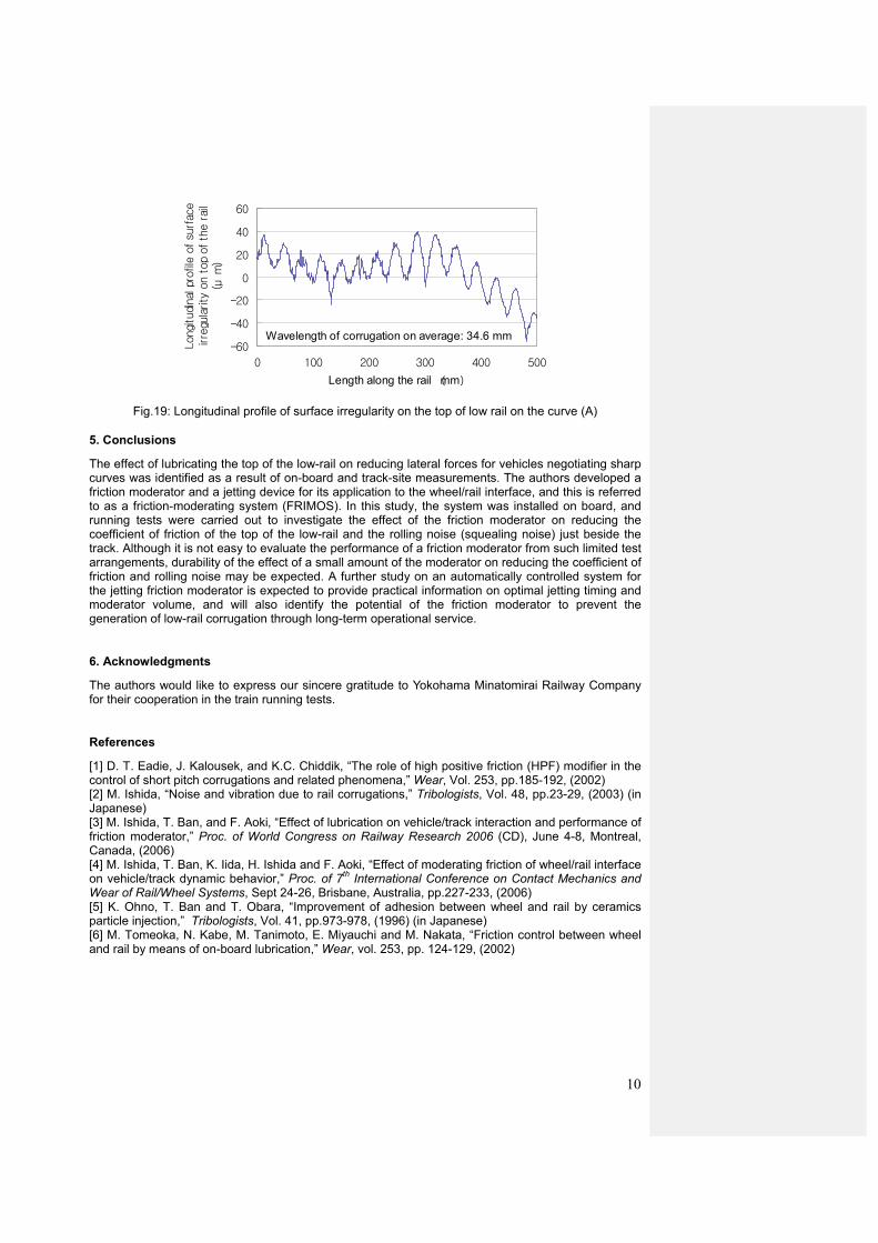
As shown in Fig.12, the sound pressure level on curve (B) was reduced by about 10 dB after applying the friction moderator. On the other hand, the results of measurement for noise on curve (A) in Fig.17 show a noise reduction of about 5 dB on average. The results of frequency analysis for the noise before and after application of the friction moderator on curves (A) and (B) are shown in Fig.18. In the figure, no difference in the sound pressure level around 250 Hz before and after application of the moderator on curve (A) is identified. Corrugations formed on the top of the low-rail on curve (A), so the longitudinal profile of the surface irregularity on the top of the low-rail was measured, and the results are shown in Fig.19. Considering that the wavelength of corrugations is 34.6 mm on average and the velocity of passing trains averages about 32 km/h, the frequency of noise caused by corrugations is estimated as 257 Hz, which is the same as the above-mentioned frequency of approximately 250 Hz. On the other hand, no corrugation was found on curve (B). Accordingly, the friction-moderating system has an effect on the reduction of squealing noise, but it is not sufficient for the reduction of noise caused by corrugation. However, since preventing corrugation is one of the main purposes of developing a friction-moderating system, the setup will be evaluated for use after removing the corrugations.
80
85
90
95
-24 -16 -8 0 8 16 24 32 40
Sou
nd p
ress
ure
leve
l(dB
)
Apply
Before applyNumber of passing axles
91 dB
86 dB
Fig.17: Effect of friction moderator on reduction of sound pressure level on curve (A)
50
60
70
80
90
100
102 103 104
(a) Curve (A) (corrugation)
Sou
nd p
ress
ure
leve
l (dB
)
After application
Before application
Frequency (Hz)
250 Hz
50
60
70
80
90
100
102 103 104
Frequency (Hz) (b) Curve (B) (no corrugation)
Before application
After application
Sou
nd p
ress
ure
leve
l (dB
)
50
60
70
80
90
100
102 103 104
(a) Curve (A) (corrugation)
Sou
nd p
ress
ure
leve
l (dB
)
After application
Before application
Frequency (Hz)
250 Hz
50
60
70
80
90
100
102 103 104
(a) Curve (A) (corrugation)
Sou
nd p
ress
ure
leve
l (dB
)
After application
Before application
Frequency (Hz)
250 Hz
50
60
70
80
90
100
102 103 104
Frequency (Hz) (b) Curve (B) (no corrugation)
Before application
After application
Sou
nd p
ress
ure
leve
l (dB
)
50
60
70
80
90
100
102 103 104
Frequency (Hz) (b) Curve (B) (no corrugation)
Before application
After application
Sou
nd p
ress
ure
leve
l (dB
)
Fig.18: Results of frequency analysis for the noise before and after application of the friction moderator in the curve (A) and (B)
10
-60
-40
-20
0
20
40
60
0 100 200 300 400 500
Length along the rail (mm)
Longi
tudi
nal
pro
file
of su
rfac
eirre
gula
rity
on t
op
of th
e r
ail
(μm
)
Wavelength of corrugation on average: 34.6 mm
Fig.19: Longitudinal profile of surface irregularity on the top of low rail on the curve (A)
5. Conclusions
The effect of lubricating the top of the low-rail on reducing lateral forces for vehicles negotiating sharp curves was identified as a result of on-board and track-site measurements. The authors developed a friction moderator and a jetting device for its application to the wheel/rail interface, and this is referred to as a friction-moderating system (FRIMOS). In this study, the system was installed on board, and running tests were carried out to investigate the effect of the friction moderator on reducing the coefficient of friction of the top of the low-rail and the rolling noise (squealing noise) just beside the track. Although it is not easy to evaluate the performance of a friction moderator from such limited test arrangements, durability of the effect of a small amount of the moderator on reducing the coefficient of friction and rolling noise may be expected. A further study on an automatically controlled system for the jetting friction moderator is expected to provide practical information on optimal jetting timing and moderator volume, and will also identify the potential of the friction moderator to prevent the generation of low-rail corrugation through long-term operational service.
6. Acknowledgments
The authors would like to express our sincere gratitude to Yokohama Minatomirai Railway Company for their cooperation in the train running tests.
References
[1] D. T. Eadie, J. Kalousek, and K.C. Chiddik, “The role of high positive friction (HPF) modifier in the control of short pitch corrugations and related phenomena,” Wear, Vol. 253, pp.185-192, (2002) [2] M. Ishida, “Noise and vibration due to rail corrugations,” Tribologists, Vol. 48, pp.23-29, (2003) (in Japanese) [3] M. Ishida, T. Ban, and F. Aoki, “Effect of lubrication on vehicle/track interaction and performance of friction moderator,” Proc. of World Congress on Railway Research 2006 (CD), June 4-8, Montreal, Canada, (2006) [4] M. Ishida, T. Ban, K. Iida, H. Ishida and F. Aoki, “Effect of moderating friction of wheel/rail interface on vehicle/track dynamic behavior,” Proc. of 7th International Conference on Contact Mechanics and Wear of Rail/Wheel Systems, Sept 24-26, Brisbane, Australia, pp.227-233, (2006) [5] K. Ohno, T. Ban and T. Obara, “Improvement of adhesion between wheel and rail by ceramics particle injection,” Tribologists, Vol. 41, pp.973-978, (1996) (in Japanese) [6] M. Tomeoka, N. Kabe, M. Tanimoto, E. Miyauchi and M. Nakata, “Friction control between wheel and rail by means of on-board lubrication,” Wear, vol. 253, pp. 124-129, (2002)