Embed Size (px)
Citation preview
ConnectPort® LTS
User’s Guide ConnectPort LTS 8, ConnectPort LTS 8 MEI,
ConnectPort LTS 8 W, ConnectPort LTS 8 MEI W,
ConnectPort LTS 16, ConnectPort LTS 16 MEI,
ConnectPort LTS 16 W, ConnectPort LTS 16 MEI W,
ConnectPort LTS 16 MEI 2AC
ConnectPort LTS 32, ConnectPort LTS 32 MEI,
ConnectPort LTS 32 W, ConnectPort LTS 32 MEI W
90001001_C

2
© Digi International Inc.2012. All Rights Reserved.
Digi, Digi International, the Digi logo, ConnectPort, XBee, and RealPort are trademarks or
registered trademarks of Digi International, Inc. in the United States and other countries worldwide.
All other trademarks are the property of their respective owners.
Information in this document is subject to change without notice and does not represent a
commitment on the part of Digi International.
Digi provides this document ―as is,‖ without warranty of any kind, either expressed or implied,
including, but not limited to, the implied warranties of fitness or merchantability for a particular
purpose. Digi may make improvements and/or changes in this manual or in the product(s) and/or
the program(s) described in this manual at any time.
This product could include technical inaccuracies or typographical errors. Changes are periodically
made to the information herein; these changes may be incorporated in new editions of the
publication.
Notice to Users
This equipment is for indoor use and all the communication wiring should be limited to inside of the
building.

3
Contents
Contents ............................................................................................................................................... 3
1. About this guide .......................................................................................................................... 7
Purpose ........................................................................................................................................ 7
Audience ...................................................................................................................................... 7
Scope ........................................................................................................................................... 7
Where to find more information .................................................................................................. 7
General release documentation ............................................................................................ 7
Additional product information on www.digi.com .............................................................. 8
Digi contact information .............................................................................................................. 8
2. Introduction ................................................................................................................................. 9
Important Safety Information ...................................................................................................... 9
The ConnectPort LTS Family .................................................................................................... 10
Features ...................................................................................................................................... 10
User interfaces ................................................................................................................... 10
Quick reference for configuring features ........................................................................... 11
Hardware and network interface features .......................................................................... 15
Configurable network services .......................................................................................... 15
IP protocol support ............................................................................................................. 16
IP address assignment alternatives ..................................................................................... 21
Alarms ................................................................................................................................ 23
Modem emulation .............................................................................................................. 23
Security features ................................................................................................................ 24
Configuration management ................................................................................................ 25
Supported connections and data paths ....................................................................................... 26
Network services ................................................................................................................ 26
Network/serial clients ........................................................................................................ 28
Configuration capabilities and interfaces .................................................................................. 30
Configuration capabilities .................................................................................................. 30
Configuration interfaces .................................................................................................... 30
Digi Device Discovery utility ............................................................................................ 31

4
The Web interface .............................................................................................................. 33
Command-line interface..................................................................................................... 34
Simple Network Management Protocol (SNMP) .............................................................. 35
LCD panel .......................................................................................................................... 36
Monitoring capabilities and interfaces....................................................................................... 37
LCD panel .......................................................................................................................... 38
Administration tasks .................................................................................................................. 38
3. Configuration ............................................................................................................................. 39
Alternate methods for assigning an IP address .......................................................................... 39
Configure an IP address using DHCP ................................................................................ 39
Configure an IP address using Auto-IP .............................................................................. 39
Configure an IP address from the command-line interface ................................................ 40
Test the IP address configuration ....................................................................................... 40
Configuration through the web interface ................................................................................... 41
Open the web interface ...................................................................................................... 41
Organization of the web interface ...................................................................................... 45
Change the IP address from the web interface, as needed ................................................. 49
Network configuration settings .......................................................................................... 50
Serial port settings ............................................................................................................. 61
Alarms ................................................................................................................................ 75
System settings .................................................................................................................. 77
User settings ....................................................................................................................... 81
Peripheral ........................................................................................................................... 86
Applications ....................................................................................................................... 90
PPP configuration .............................................................................................................. 93
Configuration through the command line ................................................................................ 101
Access the command line ................................................................................................ 101
Verify device support of commands ................................................................................ 102
Configuration through Simple Network Management Protocol (SNMP) ............................... 105
4. Monitoring and management ................................................................................................... 106
Monitoring capabilities in the web interface ........................................................................... 106
Display system information ............................................................................................. 106
Manage connections and services .................................................................................... 116

5
Monitoring capabilities from the command line ..................................................................... 117
Commands for displaying device information and statistics ........................................... 117
Commands for managing connections and sessions ........................................................ 120
Monitoring Capabilities from SNMP ...................................................................................... 121
5 Administration tasks ................................................................................................................ 122
Administration from the web interface .................................................................................... 122
File management .............................................................................................................. 123
Administration from the command-line interface ................................................................... 130
6 LCD interface: configuration, monitoring, and diagnostics .................................................... 131
Basic keypad operation and LCD display ............................................................................... 131
Keys ................................................................................................................................. 131
Keypad operations ........................................................................................................... 132
Configuration using the LCD interface ................................................................................... 133
Change IP settings ............................................................................................................ 133
Change the hostname ....................................................................................................... 136
Change the DNS configuration ........................................................................................ 138
Monitoring using the LCD interface ....................................................................................... 139
Diagnostics using the LCD interface ....................................................................................... 139
Miscellaneous functions in LCD interface .............................................................................. 140
Factory Reset ................................................................................................................... 140
LED Settings .................................................................................................................... 141
7 Disaster recovery ..................................................................................................................... 142
Restore Digi ConnectPort LTS to Factory Default Settings .................................................... 142
8 Hardware specifications .......................................................................................................... 144
9 Regulatory Information and Certifications .............................................................................. 145
FCC certifications and regulatory information (USA only) .................................................... 145
FCC Part 15 Class B ........................................................................................................ 145
Radio Frequency Interface (RFI) (FCC 15.105) .............................................................. 145
Labeling Requirements (FCC 15.19) ............................................................................... 145
Modifications (FCC 15.21) .............................................................................................. 146
Declaration of Conformity ....................................................................................................... 146
Industry Canada (IC) certifications ......................................................................................... 146
Safety statements ..................................................................................................................... 147

6
5.10 Ignition of Flammable Atmospheres ................................................................... 147
Potentially Hazardous Atmospheres ................................................................................ 147
Safety in Aircraft .............................................................................................................. 147
Safety in Hospitals ........................................................................................................... 147
Pacemakers ...................................................................................................................... 147
Persons with Pacemakers: ................................................................................................ 147
Rack-mountable: .............................................................................................................. 148
Lithium Battery ................................................................................................................ 149
Modem ............................................................................................................................. 149
Cabling ............................................................................................................................. 149

7
1. About this guide
Purpose
This guide describes and shows how to configure, monitor, and administer ConnectPort LTS
products.
Audience
This guide is intended for those responsible for setting up ConnectPort LTS products. It assumes
some familiarity with networking concepts and protocols.
Scope
This guide focuses on configuration, monitoring, and administration of ConnectPort LTS products.
It does not cover hardware details beyond a certain level, application development, or customization.
Where to find more information
In addition to this guide, find additional product and feature information in these documents:
General release documentation
These documents are of interest to end users:
Online help and tutorials in the web interface for the product
Digi Connect Hardware Reference Manuals
Quick Start Guides
RealPort® Installation Guide
Digi Connect Family Customization and Integration Guide
Release Notes
Cabling Guides
Python developer Wiki

8
Additional product information on www.digi.com
In addition to the previous documents, product information is available on the Digi website,
www.digi.com, including:
Support Forums
Knowledge Base
Data sheets/product briefs
Application/solution guides
Digi contact information
For more information about Digi products, or for customer service and technical support, contact
Digi International.
To Contact Digi International by: Use:
Digi International
11001 Bren Road East
Minnetonka, MN 55343
U.S.A.
World Wide Web: http://www.digi.com/support/
email http://www.digi.com/support/
Telephone (U.S.) (952) 912-3444 or (877) 912-3444
Telephone (other locations) +1 (952) 912-3444 or (877) 912-3444

9
2. Introduction
This chapter introduces ConnectPort LTS products, types of supported connections and data paths,
and the interface options available for configuration, monitoring, and administration tasks.
Important Safety Information
To avoid contact with electrical current:
Never install electrical wiring during an electrical storm.
Never install an Ethernet connection in wet locations unless that connector is specifically
designed for wet locations.
Use caution when installing or modifying Ethernet lines.
Use a screwdriver and other tools with insulated handles.
Wear safety glasses or goggles.
Do not place Ethernet wiring or connections in any conduit, outlet or junction box containing
electrical wiring.
Installation of inside wire may bring you close to electrical wire, conduit, terminals and other
electrical facilities. Extreme caution must be used to avoid electrical shock from such facilities.
Avoid contact with all such facilities.
Ethernet wiring must be at least 6 feet from bare power wiring or lightning rods and associated
wires, and at least 6 inches from other wire (antenna wires, doorbell wires, wires from
transformers to neon signs), steam or hot water pipes, and heating ducts.
Do not place an Ethernet connection where it would allow a person to use an Ethernet device
while in a bathtub, shower, swimming pool, or similar hazardous location.
Protectors and grounding wire placed by the service provider must not be connected to,
removed, or modified by the customer.
Do not touch no insulated Ethernet wiring if lightning is likely!
External Wiring: Any external communications wiring installed needs to be constructed to all
relevant electrical codes. In the United States this is the National Electrical Code Article 800.
Contact a licensed electrician for details.

10
The ConnectPort LTS Family
ConnectPort LTS (Linux Terminal Server) products provide serial over Ethernet connectivity for
applications today and into the future. They support IPv4 and IPv6 Ethernet protocols. The
ConnectPort LTS MEI product is the same size as the ConnectPort LTS (RS-232 only version) and
is the fastest multi-port device with a Multiple Electrical Interface (MEI) in the industry.
Features
This is an overview of key product features. Firmware features are covered in more detail in the
next three chapters. For hardware specifications, see
http://www.digi.com/products/serialservers/connectportlts#specs. See also Chapter 6, "Regulatory
Information and certifications.‖
User interfaces
There are several user interfaces for configuration and monitoring, including:
A web-based interface.
A command-line interface.
Simple Network Management Protocol (SNMP).
An LCD Panel.
For additional details on these user interfaces, see "Configuration interfaces" and
"Monitoring interfaces.‖ Some user interfaces can be customized.

11
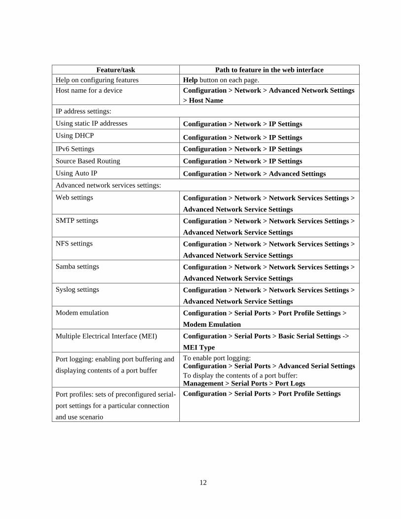
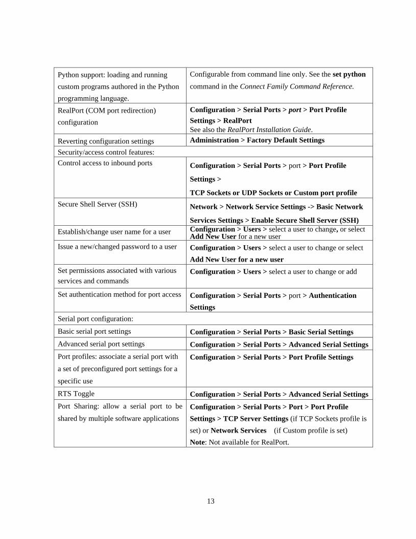
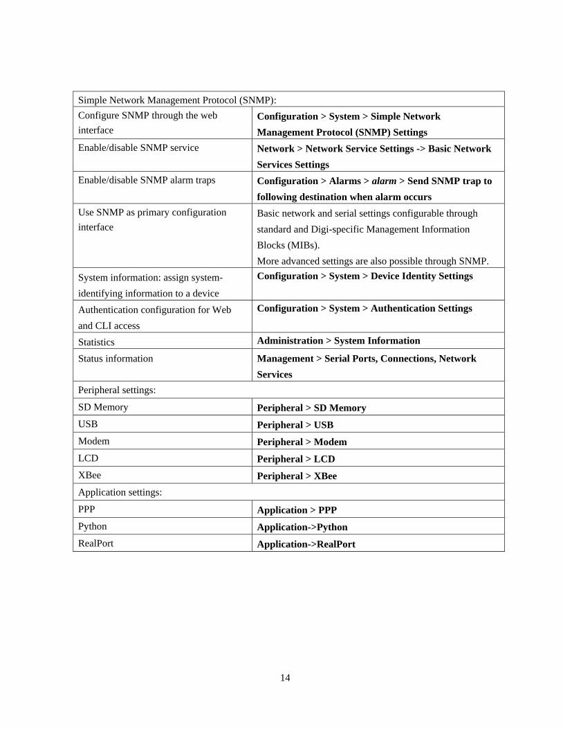
Quick reference for configuring features
This guide primarily focuses on configuration, monitoring, and administration tasks from the web
interface. This table provides a quick reference for configuring features and performing device tasks,
and where to find the features and settings in the web interface and this guide.
Some features are configurable from the command line interface only. In those cases, the
commands that configure the feature are noted. The command descriptions are in the ConnectPort
LTS Command Reference.
Feature/task Path to feature in the web interface
Administration/Configuration management:
File management: uploading and
downloading files, such as applet files,
and custom splash screens.
Administration > File Management
See also the Digi Connect Family Customization and
Integration Guide for information on uploading and
downloading files used to customize a the product’s look-
and-feel.
Python program file management. Administration > File Management
Backup/restore configuration settings Administration > Backup/Restore
Note: TFTP or BOOTP required if backing up from the
command line.
Update firmware Administration > Update Firmware
Reset configuration to factory defaults Administration > Factory Default Settings
System information, including device
identifiers and statistics
Administration > System Information
Reboot the device Administration > Reboot
Alarms Configuration > Alarms
Autoconnection: automatically connect a
user to a server or network device
Configuration > Serial Ports > port > Profile Settings >
TCP Sockets > Automatically establish TCP connections
Connection management:
Manage serial port connections Management > Serial Ports
Manage active PPP connections Management > Connections > Active PPP Connections
Manage active system connections Management > Connections > Active System
Connections
Domain Name System (DNS) Client Configuration > Network > DNS > Primary DNS and
Secondary DNS
Ethernet settings Configuration > Network > Advanced Network Settings
12
Feature/task Path to feature in the web interface
Help on configuring features Help button on each page.
Host name for a device Configuration > Network > Advanced Network Settings
> Host Name
IP address settings:
Using static IP addresses Configuration > Network > IP Settings
Using DHCP Configuration > Network > IP Settings
IPv6 Settings Configuration > Network > IP Settings
Source Based Routing Configuration > Network > IP Settings
Using Auto IP Configuration > Network > Advanced Settings
Advanced network services settings:
Web settings Configuration > Network > Network Services Settings >
Advanced Network Service Settings
SMTP settings Configuration > Network > Network Services Settings >
Advanced Network Service Settings
NFS settings Configuration > Network > Network Services Settings >
Advanced Network Service Settings
Samba settings Configuration > Network > Network Services Settings >
Advanced Network Service Settings
Syslog settings Configuration > Network > Network Services Settings >
Advanced Network Service Settings
Modem emulation Configuration > Serial Ports > Port Profile Settings >
Modem Emulation
Multiple Electrical Interface (MEI) Configuration > Serial Ports > Basic Serial Settings ->
MEI Type
Port logging: enabling port buffering and
displaying contents of a port buffer
To enable port logging: Configuration > Serial Ports > Advanced Serial Settings
To display the contents of a port buffer: Management > Serial Ports > Port Logs
Port profiles: sets of preconfigured serial-
port settings for a particular connection
and use scenario
Configuration > Serial Ports > Port Profile Settings
13
Python support: loading and running
custom programs authored in the Python
programming language.
Configurable from command line only. See the set python
command in the Connect Family Command Reference.
RealPort (COM port redirection)
configuration
Configuration > Serial Ports > port > Port Profile
Settings > RealPort
See also the RealPort Installation Guide.
Reverting configuration settings Administration > Factory Default Settings
Security/access control features:
Control access to inbound ports Configuration > Serial Ports > port > Port Profile
Settings >
TCP Sockets or UDP Sockets or Custom port profile
Secure Shell Server (SSH) Network > Network Service Settings -> Basic Network
Services Settings > Enable Secure Shell Server (SSH)
Establish/change user name for a user Configuration > Users > select a user to change, or select Add New User for a new user
Issue a new/changed password to a user Configuration > Users > select a user to change or select
Add New User for a new user
Set permissions associated with various
services and commands
Configuration > Users > select a user to change or add
Set authentication method for port access Configuration > Serial Ports > port > Authentication
Settings
Serial port configuration:
Basic serial port settings Configuration > Serial Ports > Basic Serial Settings
Advanced serial port settings Configuration > Serial Ports > Advanced Serial Settings
Port profiles: associate a serial port with
a set of preconfigured port settings for a
specific use
Configuration > Serial Ports > Port Profile Settings
RTS Toggle Configuration > Serial Ports > Advanced Serial Settings
Port Sharing: allow a serial port to be
shared by multiple software applications
Configuration > Serial Ports > Port > Port Profile
Settings > TCP Server Settings (if TCP Sockets profile is
set) or Network Services (if Custom profile is set)
Note: Not available for RealPort.
14
Simple Network Management Protocol (SNMP):
Configure SNMP through the web
interface
Configuration > System > Simple Network
Management Protocol (SNMP) Settings
Enable/disable SNMP service Network > Network Service Settings -> Basic Network
Services Settings
Enable/disable SNMP alarm traps Configuration > Alarms > alarm > Send SNMP trap to
following destination when alarm occurs
Use SNMP as primary configuration
interface
Basic network and serial settings configurable through
standard and Digi-specific Management Information
Blocks (MIBs).
More advanced settings are also possible through SNMP.
System information: assign system-
identifying information to a device
Configuration > System > Device Identity Settings
Authentication configuration for Web
and CLI access
Configuration > System > Authentication Settings
Statistics Administration > System Information
Status information Management > Serial Ports, Connections, Network
Services
Peripheral settings:
SD Memory Peripheral > SD Memory
USB Peripheral > USB
Modem Peripheral > Modem
LCD Peripheral > LCD
XBee Peripheral > XBee
Application settings:
PPP Application > PPP
Python Application->Python
RealPort Application->RealPort
15
Hardware and network interface features
For detailed hardware specifications and network interface information, go to:
http://www.digi.com/products/serialservers/connectportlts#specs.
See also the data sheet for your Digi product.
Configurable network services
Access to network services can be enabled and disabled. This means that a device’s use of network
services can be restricted to those strictly needed by the device. To improve device security,
non-secure services, such as Telnet, can be disabled. Network services that can be enabled or
disabled include:
Advanced Digi Discovery Protocol (ADDP): can enable or disable ADDP, but cannot change
its network port number.
RealPort
Encrypted RealPort
HTTP/HTTPS
Line Printer Daemon (LPD)
Remote Login (rlogin)
Remote Shell (rsh)
Simple Network Management Protocol (SNMP)
Telnet
Secure Shell Server (SSH)
In the web interface, access to network services is enabled and disabled on the Network Services
page of Network Configuration. For more information, see ―Basic Network Services Settings‖ on
page 53.
In the command-line interface, network services are enabled and disabled through the set service
command. See the ConnectPort LTS Command Reference for the set service command description.

16
IP protocol support
All ConnectPort LTS products include a robust on-board TCP/IP stack with a built-in web server.
Supported protocols include, unless otherwise noted:
Transmission Control Protocol (TCP)
User Datagram Protocol (UDP)
Dynamic Host Configuration Protocol (DHCP)
Simple Network Management Protocol (SNMP)
Secure Sockets Layer (SSL)/Transport Layer Security (TLS)
Telnet Com Port Control Option (Telnet).See "Serial data communication over TCP and UDP"
for additional information.
Remote Login (rlogin)
Line Printer Daemon (LPD)
HyperText Transfer Protocol (HTTP)/HyperText Transfer Protocol over Secure Socket Layer
(HTTPS)
Simple Mail Transfer Protocol (SMTP)
Internet Control Message Protocol (ICMP)
Internet Group Management Protocol (IGMP)
Address Resolution Protocol (ARP)
Advanced Digi Discovery Protocol (ADDP)
17
Following is an overview of some of the services provided by these protocols.
Serial data communication over TCP and UDP
ConnectPort LTS products support serial data communication over TCP and UDP. Key features
include:
Serial data communication over TCP, also known as autoconnect and tcpserial can
automatically perform the following functions:
– Establish bidirectional TCP connections, known as autoconnections, between the serial device
and a server or other network device. Autoconnections can be made based on data and or
serial hardware signals.
– Control forwarding characteristics based on patterns
– Allow incoming raw, Telnet, and SSL/TLS (secure-socket) connections
Serial data communication over UDP, also known as udpserial, can automatically perform the
following functions:
– Digi Connect products can automatically send serial data to one or more devices or systems
on the network using UDP sockets. Options for sending data include whether specific data
is on the serial line, a specific time period has elapsed, or after the specified number of
bytes has been received on the serial port.
– Control forwarding characteristics based on patterns.
– Support incoming datagrams from multiple destinations.
– Support outgoing datagrams sent to multiple destinations.
TCP/UDP forwarding characteristics.
Extended communication control on TCP/UDP data paths.
– Timeout
– Hangup
– User-configurable Socket ID string (text string identifier on autoconnect only)
Dynamic Host Configuration Protocol (DHCP)
Dynamic Host Configuration Protocol (DHCP) can be used to automatically assign IP addresses,
deliver TCP/IP stack configuration parameters such as the subnet mask and default router, and
provide other configuration information. For further details, see "Alternate methods for assigning an
IP address.‖ on page 39.

18
Auto-IP
Auto-IP is a protocol that will automatically assign an IP address from a reserved pool of standard
Auto-IP addresses to the computer on which it is installed. ConnectPort LTS is set to obtain its IP
address automatically from a DHCP server. But if the DHCP server is unavailable or nonexistent,
Auto-IP will assign the device an IP address. For further details, see "IP address assignment
alternatives.‖
Simple Network Management Protocol (SNMP)
Simple Network Management Protocol (SNMP) is a protocol for managing and monitoring network
devices. SNMP architecture enables a network administrator to manage nodes--servers,
workstations, routers, switches, hubs, etc.--on an IP network; manage network performance, find
and solve network problems, and plan for network growth. ConnectPort LTS products support
SNMP Versions 1, 2, and 3. For more information on SNMP as a device-management interface, see
"Simple Network Management Protocol (SNMP).‖
Supported RFCs and MIBs
ConnectPort LTS products support these SNMP-related Request for Comments (RFCs) and
Management Information Bases (MIBs):
RFC 1213 - Management Information Base (MIB) II
RFC 1215 - Generic Traps (coldStart, linkUp, authenticationFailure, Login only)
RFC 1316 - Character MIB
RFC 1317 - RS-232 MIB
DIGI-DEVICE-INFO.mib - A Digi enterprise MIB for displaying device information.
DIGI-SERIAL-ALARM-TRAPS.mib - A Digi enterprise MIB for sending alarms as SNMP
traps.
DIGI-CONNECPORT-LTS.mib - A Digi enterprise MIB for configuring ConnectPort LTS.
Supported SNMP traps
SNMP traps can be enabled or disabled. Supported SNMP traps include:
Authentication failure
Login
Cold start
Link up
Alarms can be issued in the form of SNMP traps

19
Secure Sockets Layer (SSL)/Transport Layer Security (TLS)
Secure Sockets Layer (SSL)/Transport Layer Security (TLS) are used to provide authentication and
encryption for ConnectPort LTS products. For more information, see ‖Security features.‖
Telnet
ConnectPort LTS products support the following types of Telnet connections:
Telnet Client
Telnet Server
Reverse Telnet, often used for console management or device management
Telnet Autoconnect
For more information on these connections, see "Supported connections and data paths.‖ Access to
Telnet network services can be enabled or disabled.
Remote Login (rlogin)
Users can perform logins to remote systems (rlogin). Access to rlogin service can be enabled or
disabled.
Line Printer Daemon (LPD)
The Line Printer Daemon (LPD) allows network printing over a serial port. Each serial port has a
dedicated LPD server that is independently configurable. Access to LPD service can be enabled or
disabled.
HyperText Transfer Protocol (HTTP)
HyperText Transfer Protocol over Secure Socket Layer (HTTPS)
ConnectPort LTS products provide web pages for configuration that can be secured by requiring a
user login.
Internet Control Message Protocol (ICMP)
ICMP statistics can be displayed, including the number of messages received, bad messages
received, and destination unreachable messages received.

20
Point-to-Point Protocol (PPP)
The Point-to-Point Protocol (PPP) transports multi-protocol packets over point-to-point links. PPP
encapsulates the data packet, allows the server to inform the dial-up client of its IP address (or client
to request the IP address), authenticates the exchange, negotiates multiple protocols, and
reassembles the data packet for network communication.
Advanced Digi Discovery Protocol (ADDP)
The Advanced Digi Discovery Protocol (ADDP) runs on any operating system capable of sending
multicast IP packets on a network. ADDP allows the system to identify all ADDP-enabled
ConnectPort LTS products attached to a network by sending out a multicast packet. The
ConnectPort LTS products respond to the multicast packet and identify themselves to the client
sending the multicast. ADDP needs to communicate with the TCP/IP stack using UDP. The TCP/IP
stack should be able to receive multicast packets and transmit datagrams on a network. Not all Digi
devices support ADDP. Access to ADDP service can be enabled or disabled, but the network port
number for ADDP cannot be changed from its default.
Secure Shell (SSH)
ConnectPort LTS units support the following types of Secure Shell (SSH) connections: Reverse
SSH and SSH Autoconnect. Limited use of SSH via SSH client is available from the Linux
command line/bash shell. For more information on these connections, see "Supported connections
and data paths.‖ Access to Secure Shell network services can be enabled or disabled.

21
IP address assignment alternatives
There are several ways to assign an IP address to a ConnectPort LTS product:
Static IP: Assign a specific IP address to a device, through the Digi Device Discovery Utility,
the web interface, LCD, Digi Device Discovery tool, or the command-line interface.
Using Dynamic Host Configuration Protocol (DHCP). Dynamic Host Configuration Protocol
(DHCP) is an Internet protocol for automating the configuration of computers that use TCP/IP.
DHCP can be used to automatically assign IP addresses, to deliver TCP/IP stack configuration
parameters such as the subnet mask and default router, and to provide other configuration
information. All ConnectPort LTS products have a DHCP server enabled by default.
Auto Private IP Addressing (APIPA), also known as Auto-IP: A standard protocol that will
automatically assign an IP address from a reserved pool of standard Auto-IP addresses to the
computer on which it is installed. The device is set to obtain its IP address automatically from a
DHCP server. But if the DHCP server is unavailable or nonexistent, Auto-IP will assign the
device an IP address. If DHCP is enabled or responds later ADDP is used, both will override
the Auto-IP address previously assigned.
Using the Digi Device Discovery Utility, a Digi utility available on the Digi website. This
utility searches for and displays Digi devices and allows you to display and change
configuration settings for a device from its web or command-line interfaces. Clicking
Configure network settings in the utility allows you to configure network settings, including
the IP address.
Using the LCD panel. ConnectPort LTS products have an LCD panel which can be used to
perform basic configuration tasks, including setting the IP address, as well as monitoring and
diagnostics tasks. See ―LCD interface: configuration, monitoring, and diagnostics‖ on page 131.
Access via the ―console‖ port. ConnectPort LTS products have a specific port for configuring
device settings, labeled ―console‖ port. This port allows for a login, with serial settings of 9600
baud, 8 data bits, and 1 stop bit. The standard serial ports do not provide a login by default, and
do not provide access to configuration settings. Only the ―console‖ port allows access to
configuration settings.
22
RealPort software
ConnectPort LTS products use the patented RealPort COM/TTY port redirection for Microsoft
Windows, UNIX, and Linux environments. RealPort software provides a virtual connection to serial
devices, no matter where they reside on the network. The software is installed directly on the host
PC and allows applications to talk to devices across a network as though the devices were directly
attached to the host. Actually, the devices are connected to a Digi device somewhere on the network.
RealPort is unique among COM port re-directors because it is the only implementation that allows
multiple connections to multiple ports over a single TCP/IP connection. Other implementations
require a separate TCP/IP connection for each serial port. Unique features also include full
hardware and software flow control, as well as tunable latency and throughput.
Access to RealPort services can be enabled or disabled.
Encrypted RealPort
ConnectPort LTS products also support RealPort software with encryption. Encrypted RealPort
offers a secure Ethernet connection between the COM or TTY port and a device server or terminal
server.
Encryption prevents internal and external snooping of data across the network by encapsulating the
TCP/IP packets in a Secure Sockets Layer (SSL) connection and encrypting the data using
Advanced Encryption Standard (AES), one of the latest, most efficient security algorithms. Access
to Encrypted RealPort services can be enabled or disabled.
Digi RealPort with encryption driver has earned Microsoft Windows Hardware Quality Lab
(WHQL) certification.
Drivers are available for a wide range of operating systems, including Microsoft Windows Server
2003, Windows XP, Windows 2000, Windows 7, Windows Server 2008, Windows ME; SCO Open
Server ; Linux ; AIX ; Sun Solaris SPARC ; Intel ; and HP-UX . It is ideal for financial,
retail/point-of-sale, government or any application requiring enhanced security to protect sensitive
information.

23
Alarms
ConnectPort LTS products can be configured to issue alarms, in the form of email message or
SNMP traps, when certain device events occur. These events include certain data patterns being
detected in the data stream. Receiving alarms about these conditions provides the advantage of
notifications being issued when events occur, rather than having to monitor the device on an
ongoing basis to determine whether these events have occurred. For more information on
configuring alarms, see "Alarms.‖
Modem emulation
ConnectPort LTS products include a configuration profile that allows the device to emulate a
modem. Modem emulation sends and receives modem responses to a serial device over TCP/IP
(including Ethernet) instead of Public Switched Telephone Network (PSTN). The modem emulation
profile allows maintaining a current software application but using it over the less expensive
Ethernet network. In addition, Telnet processing can be enabled or disabled on the incoming and
outgoing modem-emulation connections.
24
Security features
Security-related features in ConnectPort LTS products include:
Secure access and authentication:
– One password, one permission level.
– Can issue passwords to device users.
– Can selectively enable and disable network services such as ADDP, RealPort, Encrypted
RealPort, HTTP/HTTPS, LPD, Remote Login, Remote Shell, SNMP, Telnet and Secure
Shell (SSH).
– Can control access to inbound ports.
– Secure sites for configuration: HTML pages for configuration have appropriate security.
– User and user group access permissions, which control user access to various features and
the level of control they have over them (view settings or change settings).
Encryption:
– Strong Secure Sockets Layer (SSL) V3.0/ Transport Layer Security (TLS) V1.0-based
encryption: DES (58-bit), 3DES (168-bit), AES (128-/156-bit.
– Strong Secure Sockets Layer (SSL) V3.0/ Transport Layer Security (TLS) V1.0-based
encryption: DES (64-bit), 3DES (192-bit), AES (128-/192-/256-bit).
– Encrypted RealPort offers encryption for the Ethernet connection between the COM/TTY
port and the ConnectPort LTS product.
SNMP security:
– Authorization: Changing public and private community names is recommended to prevent
unauthorized access to the device. (SNMPv1/v2c)
– SNMPv3 support for enhanced security through SNMP.
– SNMP set commands can be disabled to make use of SNMP read-only.

25
Configuration management
Once a ConnectPort LTS product is configured and running, configuration-management tasks need
to be periodically performed, such as:
Upgrading firmware
Copying configurations to and from a remote host
Software and factory resets
Rebooting the device
Memory management
File management
For more information on these configuration-management tasks, see Chapter 4, "Administration
tasks.‖

26
Supported connections and data paths
ConnectPort LTS products allow for several kinds of connections and paths for data flow between
the ConnectPort LTS product and other entities. These connections can be grouped into two main
categories:
Network services, in which a remote entity initiates a connection to a ConnectPort LTS product.
Network/serial clients, in which a ConnectPort LTS product initiates a network connection or
opens a serial port for communication.
This discussion of connections and data paths may be helpful in understanding the effects of
enabling certain features and choosing certain settings when configuring Digi products.
Network services
A network service connection is one in which a remote entity initiates a connection to a
ConnectPort LTS product. There are several categories of network services:
Network services associated with specific serial ports
Network services associated with serial ports in general
Network services associated with the command-line interface (CLI)
Network services associated with specific serial ports
Reverse Telnet: A telnet connection is made to a ConnectPort LTS product, in which data is
passed transparently between the telnet connection and a named serial port.
Reverse raw socket: A raw TCP socket connection is made to a ConnectPort LTS product, in
which data is passed transparently between the socket and a named serial port.
Reverse TLS socket: An encrypted raw TCP socket is made to a ConnectPort LTS product, in
which data is passed transparently to and from a named serial port.
LPD: A TCP connection is made to a named serial port, in which the ConnectPort LTS product
interprets the LPD protocol and sends a print job out of the serial port.
Modem emulation, also known as Pseudo-modem (pmodem): A TCP connection is made to a
named serial port, and the connection will be ―interpreted‖ as an incoming call to the pseudo-
modem.
Console Mgmt: Allows a TCP connection.
Modem: The Modem Profile allows for attaching modem devices to the serial port to establish
or receive connections from other systems and modems.

27
Reverse SSH: An SSH connection is made to a ConnectPort LTS product, in which data is
passed transparently between the SSH connection and a named serial port.
Network services associated with serial ports in general
RealPort: A single TCP connection manages (potentially) multiple serial ports.
Modem emulation, also known as pseudo-modem (pool): A TCP connection to the ―pool‖ port
is interpreted as an incoming call to an available pseudo-modem in the ―pool‖ of available port
numbers.
rsh: ConnectPort LTS products support a limited implementation of the Remote shell (rsh)
protocol, in that a single service listens to connections and allows a command to be executed.
Only one class of commands is allowed: a single integer that specifies which serial port to
connect to. Otherwise, the resulting connection is somewhat similar to a reverse telnet or
reverse socket connection.
Network services associated with the command-line interface
Telnet or SSH: A user can Telnet or SSH directly to a ConnectPort LTS product command-line
interface.
rlogin: A user can perform a remote login (rlogin) to a ConnectPort LTS product command-line
interface.

28
Network/serial clients
A network/serial client connection is one in which a ConnectPort LTS product initiates a network
connection or opens a serial port for communication. There are several categories of network/serial
client connections:
Autoconnect behavior client connections
Command-line interface (CLI)-based clients
Modem emulation (pseudo-modem) client connections
Autoconnect behavior client connections
In client connections that involve autoconnect behaviors, a ConnectPort LTS product initiates a
network connection based on timing, serial activity, or serial modem signals. Autoconnect-related
client connections include:
Raw TCP connection: The ConnectPort LTS product initiates a raw TCP socket connection to a
remote entity.
Telnet connection: The ConnectPort LTS product initiates a TCP connection using the Telnet
protocol to a remote entity.
SSH connection: The ConnectPort LTS product initiates a TCP connection using the SSH
protocol to a remote entity.
Raw TLS encrypted connection: The ConnectPort LTS product initiates an encrypted raw TCP
socket connection to a remote entity.
Rlogin connection: The ConnectPort LTS product initiates a TCP connection using the rlogin
protocol to a remote entity.

29
Command-line interface (CLI)-based client connections
Command-line interface based client connections are available for use once a user has established a
session with the ConnectPort LTS product CLI. CLI-based client connections include:
telnet: A connection is made to a remote entity using the Telnet protocol.
bash: The ―bash‖ command provides access to the Linux bash shell.
rlogin: A connection is made to a remote entity using the Rlogin protocol.
connect: Begin communicating with a local serial port.
Modem emulation (pseudo-modem) client connections
When a port is in the modem-emulation or pseudo-modem mode, it can initiate network connections
based on AT command strings received on the serial port. The AT commands for modem emulation
are documented in the ConnectPort LTS Command Reference.

30
Configuration capabilities and interfaces
This is an overview of the configuration capabilities and interfaces for ConnectPort LTS products;
Chapter 2, "Configuration," covers them in more detail.
Configuration capabilities
Device configuration involves setting values and enabling features for such areas as:
Network configuration: Specifying the device IP address and IP settings, network-service
settings, and advanced network settings.
Serial port configuration: Specifying the serial port characteristics for the device.
Alarms: Defining whether alarms should be issued, the conditions that trigger alarms, and how
the alarms should be delivered.
Users configuration: Configuring security features, such as whether password authentication is
required for device users.
System configuration: Specifying system-identifying information, such as a device description,
contact person, and physical location.
Configuration interfaces
Several interfaces are available for configuring ConnectPort LTS products, including:
The Digi Device Discovery Utility, which locates Digi devices on a network, and allows
opening the web interface for the devices.
A web-based interface embedded with the product, providing device configuration profiles for
quick serial-port configuration and other settings.
A command-line interface (CLI).
Simple Network Management Protocol (SNMP).
LCD Panel
31
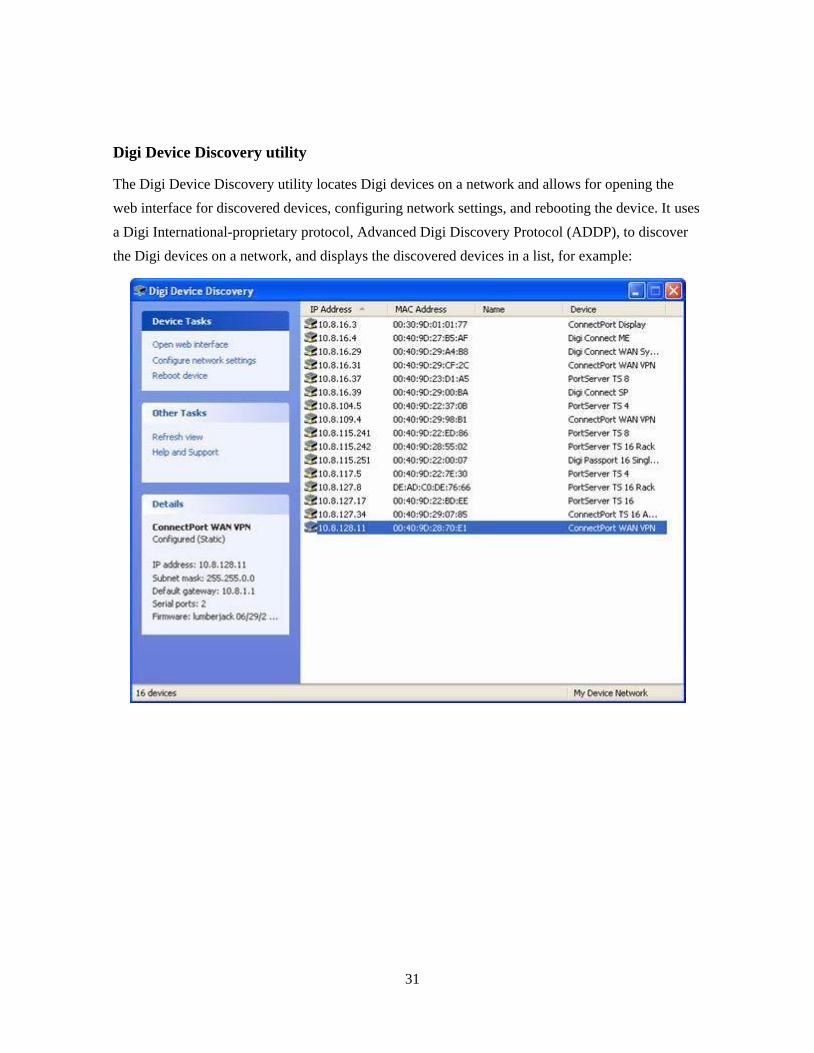
Digi Device Discovery utility
The Digi Device Discovery utility locates Digi devices on a network and allows for opening the
web interface for discovered devices, configuring network settings, and rebooting the device. It uses
a Digi International-proprietary protocol, Advanced Digi Discovery Protocol (ADDP), to discover
the Digi devices on a network, and displays the discovered devices in a list, for example:

32
Advantages of the Digi Device Discovery utility are:
It quickly locates Digi devices and basic device information, such as the device address,
firmware revision, and whether it has been configured.
ADDP runs on any operating system that can send multicast IP packets to a network. It sends
out a User Datagram Protocol (UDP) multicast packet to all devices on the network. Devices
supporting ADDP reply to this UDP multicast with their configuration information. Even
devices that do not yet have an IP address assigned or are misconfigured for the subnet can
reply to the UDP multicast packet and be displayed in device discovery results.
Disadvantages include:
Device discovery responses can be blocked by personal firewalls, Virtual Private Network
(VPN) software, and certain network equipment. Firewalls will block UDP ports 2362 and
2363 that ADDP uses to discover devices.
Not all Digi devices support ADDP.
Digi Device Discovery is available on the Digi device Software and Documentation CD. After
installation, it is available from the Start menu. Access to the ADDP service can be enabled or
disabled, but the network port number for ADDP cannot be changed from its default.
33
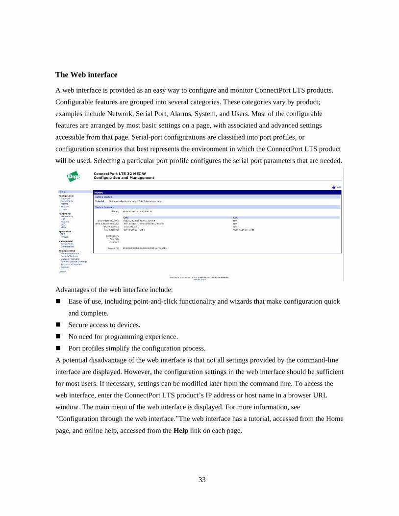
The Web interface
A web interface is provided as an easy way to configure and monitor ConnectPort LTS products.
Configurable features are grouped into several categories. These categories vary by product;
examples include Network, Serial Port, Alarms, System, and Users. Most of the configurable
features are arranged by most basic settings on a page, with associated and advanced settings
accessible from that page. Serial-port configurations are classified into port profiles, or
configuration scenarios that best represents the environment in which the ConnectPort LTS product
will be used. Selecting a particular port profile configures the serial port parameters that are needed.
Advantages of the web interface include:
Ease of use, including point-and-click functionality and wizards that make configuration quick
and complete.
Secure access to devices.
No need for programming experience.
Port profiles simplify the configuration process.
A potential disadvantage of the web interface is that not all settings provided by the command-line
interface are displayed. However, the configuration settings in the web interface should be sufficient
for most users. If necessary, settings can be modified later from the command line. To access the
web interface, enter the ConnectPort LTS product’s IP address or host name in a browser URL
window. The main menu of the web interface is displayed. For more information, see
"Configuration through the web interface.‖The web interface has a tutorial, accessed from the Home
page, and online help, accessed from the Help link on each page.

34
Command-line interface
ConnectPort LTS products can be configured by issuing commands from the command line. The
command-line interface allows communication directly without a graphical interface. For example,
the following is a command issued from the command line to set general serial configuration
options:
#> set serial port=1-32 baudrate=9600 flowcontrol=hardware
Advantages of the command-line interface include:
Flexibility. Although the command-line Interface is for experienced users and considered
complex, it allows flexibility for precise configuration alterations.
Direct communication to device or system.
Disadvantages of the command-line interface include:
Users must have experience issuing commands.
Command documentation is required.
The command line allows the greatest flexibility to configure ConnectPort LTS products, but is
also considered complex.
The command line is available through Telnet or SSH TCP/IP connections, or through serial port
using terminal emulation software such as Hyperterminal. Access to the command line from serial
ports depends on the port profile in use by the port.
See "Configuration through the command line" for more information on this interface.
See the ConnectPort LTS Command Reference for command descriptions and examples of entering
configuration commands from the command-line interface. In addition, online help is available for
the commands, through the help and ? commands.

35
Simple Network Management Protocol (SNMP)
Simple Network Management Protocol (SNMP) is a protocol for managing and monitoring network
devices. The SNMP architecture enables a network administrator to manage nodes--servers,
workstations, routers, switches, hubs, etc.--on an IP network; manage network performance, find
and solve network problems, and plan for network growth. ConnectPort LTS supports SNMP
Versions 1, 2 and 3.
Advantages of SNMP include:
SNMP is easy to implement in extensive networks.
Programming new variables is easy.
SNMP is widely used. SNMP is a standard interface that integrates well with network
management stations in an enterprise environment. Read/write capabilities are also added to
ConnectPort LTS SNMP interface.
It is easy to ―drop in‖ new devices.
Disadvantages include:
SNMP does not allow for certain task that can be performed from the web interface, such as file
management, uploading firmware, or backing up and restoring configurations.
Accessing the SNMP interface requires a tool, such as a network management station. The
management station relies on an agent at a device to retrieve or update the information at the device,
including Device configuration, status, and statistical information. This information is viewed as a
logical database, called a Management Information Base (MIB). MIB modules describe MIB
variables for a variety of device types and computer hardware and software components.

36
Standard MIBs supported
The standard MIBs supported in ConnectPort LTS products are:
MIB-II (RFC 1213) This is a MIB for managing a TCP/IP network. It is an update of the
original MIB, now called MIB-I. MIB-II contains variable definitions that describe the most
basic information needed to manage a TCP/IP network. These variable definitions are
organized into several groups, such as groups for managing the system, network interfaces,
address translation, transmission media, and various protocols, including IP, ICMP, TCP, UDP,
EGP, and SNMP.
CHARACTER-MIB (RFC 1658)
RS-232-MIB (RFC 1659).
Digi enterprise MIBs supported
In addition to the standard MIBs, ConnectPort LTS products use several Digi enterprise MIBs,
including:
DIGI-CONNECTPORT-LTS.mib: for reading/writing configuration and handling device
information. This MIB gives access to elements like port configurations, firmware revision,
device name, IP network configuration, memory, and CPU statistics.
DIGI-SERIAL-ALARM-TRAPS.mib: for handling alarms sent as SNMP traps.
Additional SNMP resources
A variety of resources about SNMP are available, including reference books, overviews, and other
files on the Internet. For an overview of the SNMP interface and the components of MIB-II, go to
http://www.rfc-editor.org/rfcsearch.html, and search for MIB-II. From the results, locate the text
file describing the SNMP interface, titled Management Information Base for Network Management
of TCP/IP-based internets: MIB-II. The text of the Digi enterprise MIBs can also be displayed.
For additional discussion of using SNMP as a device monitoring interface, see "Monitoring
Capabilities from SNMP.‖
LCD panel
The LCD panel can be used to set several configuration settings, including IP address, hostname,
and Domain Name Server (DNS) settings. For more information, see LCD interface: configuration,
monitoring, and diagnostics’ on page 131.
37
Monitoring capabilities and interfaces
There are several capabilities and interfaces for monitoring ConnectPort LTS products and
managing their connections; these are covered in more detail in Chapter 3, "Monitor and manage
Digi devices.‖
Monitoring ConnectPort LTS products includes such tasks as checking device status, viewing
information on a device, checking runtime state, viewing serial port operations, and reviewing
network statistics, and managing their connections. As with device configuration, there are several
interfaces available for monitoring ConnectPort LTS products, including the web interface
embedded with the product. SNMP, the command-line interface, and the LCD Panel.
Web interface
The web interface has several screens for monitoring ConnectPort LTS products:
Network Status
Serial Port Management: for each port, the port description, current profile, and current serial
configuration.
Connections Management: A display of all active system connections.
System Information:
General device information
Serial port information: for each port, the port description, current profile, current serial
configuration, and serial signals. This is the same information displayed by choosing Serial
Port Management.
Network statistics: statistics for IP, TCP, UDP, and ICMP
Command-line interface
Several commands can be issued from the command line to monitor devices. For a review of these
commands and what they can provide from a device-monitoring perspective, see "Monitoring
capabilities from the command line.‖
SNMP
Monitoring capabilities of SNMP include managing network performance, gathering device
statistics, and finding and solving network problems. For more information on using SNMP for
device-monitoring purposes, see "Monitoring Capabilities from SNMP.‖

38
LCD panel
The LCD panel can be used to perform several monitoring tasks. For more information, see
LCD interface: configuration, monitoring, and diagnostics’ on page 131.
Administration tasks
Periodically, administrative tasks need to be performed on ConnectPort LTS products, such as:
Uploading and managing files
Changing the password for logging onto the device
Backing up and restoring the configuration
Updating firmware
Restoring the configuration to factory defaults
Rebooting the module
As with configuration and monitoring tasks, administration can be done from a number of interfaces,
including the web interface and command line. See Chapter 4, "Administration tasks" for more
information and procedures.

39
3. Configuration
This chapter describes how to configure a ConnectPort LTS product. It covers these topics:
"Alternate methods for assigning an IP address".
"Configuration through the web interface".
"Configuration through the command line".
"Configuration through Simple Network Management Protocol (SNMP)".
"Batch capabilities for configuring multiple devices".
The primary focus of this chapter is on configuring ConnectPort LTS products through the web
interface.
Alternate methods for assigning an IP address
Configure an IP address using DHCP
An IP address can also be configured using Dynamic Host Configuration Protocol (DHCP).
This procedure assumes that the ConnectPort LTS product is configured as a DHCP client. Since
this is the default configuration, this will be the case unless the configuration has been changed.
1. Make sure the ConnectPort LTS product is not powered on.
2. If desired, set up a permanent entry for the ConnectPort LTS product on a DHCP server. While
this is not necessary to obtain an IP address via DHCP, setting up a permanent entry means the
IP address will be saved after the device is rebooted.
3. Connect the ConnectPort LTS product to the network and power it on. The IP address
configured in step 2 is assigned automatically.
Configure an IP address using Auto-IP
The standard protocol Automatic Private IP Addressing (APIPA or Auto-IP) assigns the IP address
from the reserved IP addresses in Auto-IP. Use ADDP or DHCP to find the device and assign it a
new IP address that compatible with your network. Once the unit is plugged in, Auto-IP
automatically assigns the IP address.

40
Configure an IP address from the command-line interface
The set network command configures an IP address from the command line. Include the following
parameters:
index=(1-4) : Ethernet interface index number
ip_v4=device ip: The IP v4 address for the device.
gateway_v4=gateway: The network gateway IP v4 address.
submask_v4=device submask: The device subnet mask for IP v4 address.
mode_v4=(none|static|dhcp): The configuration mode of IP v4 address.
ip_v6=device ip: The IP v6 address for the device.
gateway_v6=gateway: The network gateway IP v6 address.
submask_v6=device submask: The device subnet mask for IP v6 address.
mode_v6=(none|static|dhcp): The configuration mode of IP v6 address.
For example:
set network index=1 ip_v4=10.0.0.100 gateway_v4=10.0.0.1
submask_v4=255.255.255.0 mode_v4=static
Test the IP address configuration
Once the IP address is assigned, test the IP address configuration to be sure it works as configured.
This procedure assumes that the ConnectPort LTS product has an IP address.
1. Access the command line of a PC or other networked device.
2. Issue the following command:
ping ip address
where ip address is the address assigned to the ConnectPort LTS product. For example:
ping 192.168.2.2
41
Configuration through the web interface
Configuring ConnectPort LTS products through the web interface involves these tasks:
Change the IP address, as needed
Open the web interface
Configure network communications
Configure the serial ports
Configure alarms.
Configure system-identifying information and the settings for Simple Network Management
Protocol (SNMP)
Configure security/user features such as user names and password authentication
Configure and run applications available for use.
Manage programs authored in the Python® programming language
Open the web interface
To open the web interface, either enter the URL of the ConnectPort LTS product in a web browser
and log on to the device, if required, or use the Digi Device Discovery utility to locate it and open
its web interface.
By entering the ConnectPort LTS product IP address in a web browser
1. In the URL address bar of a web browser, enter the IP address of the device.
2. If security has not been enabled for the ConnectPort LTS product, the Home page of the web
interface is displayed. If security has been enabled for the ConnectPort LTS product, a login
dialog will be displayed. Enter the user name and password for the device. The default
username is root and the default password is dbps. If these defaults do not work, contact the
system administrator who set up the device. Then the Home page of the web interface is
displayed. See "Organization of the web interface" for an overview of using the Home page and
other linked pages.
Note The idle timeout automatically logs users out of the web interface after 60 minutes of
inactivity. This can be changed Web settings on Configuration > Network -> Network Services
Settings -> Advanced Network Services Settings.

42
By using the Digi Device Discovery utility
Alternatively, use the Digi Device Discovery Utility to locate the ConnectPort LTS product and
open its web interface.
Install Digi Device Discovery utility
The Digi Device Discovery Utility is available on the Software and Documentation CD. If this
utility is not already available on your computer, follow these steps.
1. On the main page Software and Documentation CD, click software - install optional software.
2. Select Device Discovery Utility and click Install.
3. Follow the prompts of the Setup Wizard to install the Digi Device Discovery Utility software.
43
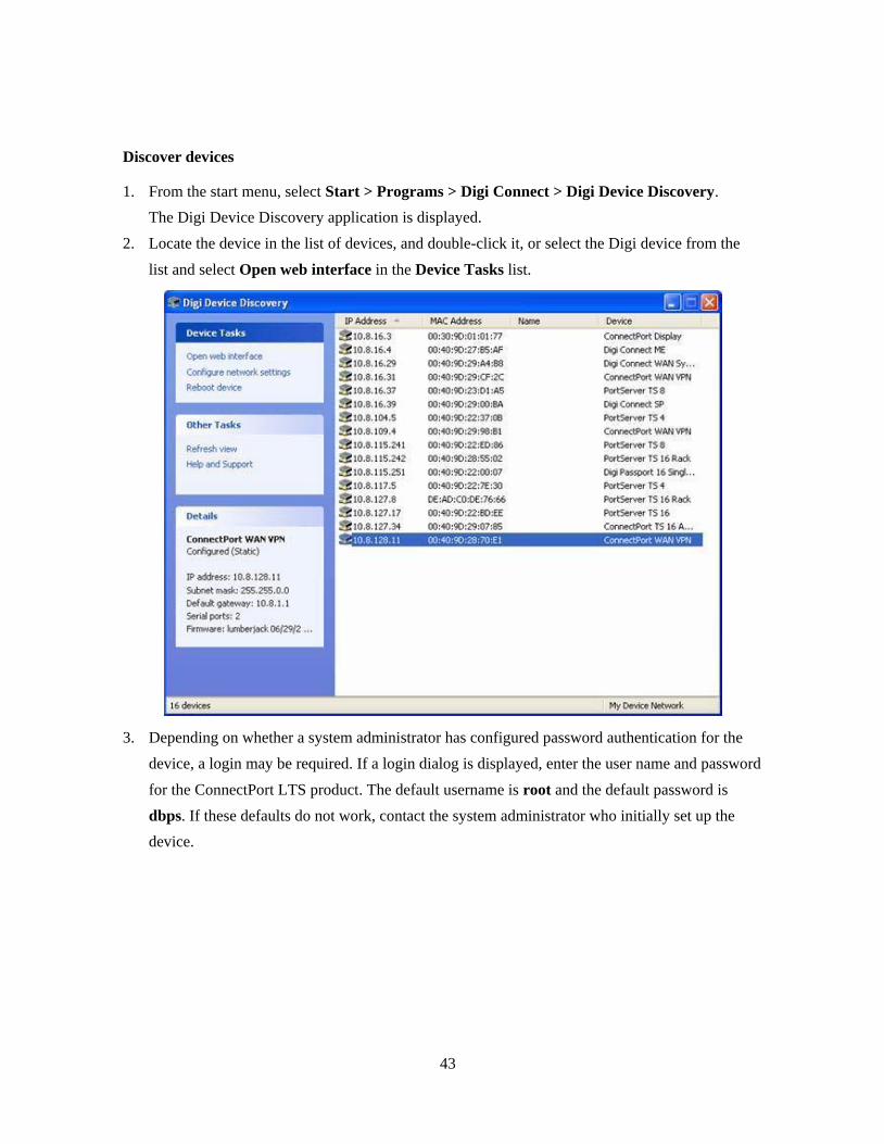
Discover devices
1. From the start menu, select Start > Programs > Digi Connect > Digi Device Discovery.
The Digi Device Discovery application is displayed.
2. Locate the device in the list of devices, and double-click it, or select the Digi device from the
list and select Open web interface in the Device Tasks list.
3. Depending on whether a system administrator has configured password authentication for the
device, a login may be required. If a login dialog is displayed, enter the user name and password
for the ConnectPort LTS product. The default username is root and the default password is
dbps. If these defaults do not work, contact the system administrator who initially set up the
device.
44
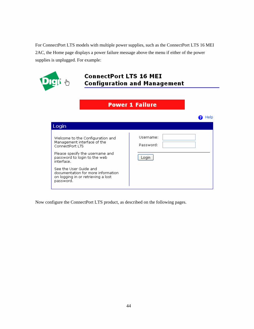
For ConnectPort LTS models with multiple power supplies, such as the ConnectPort LTS 16 MEI
2AC, the Home page displays a power failure message above the menu if either of the power
supplies is unplugged. For example:
Now configure the ConnectPort LTS product, as described on the following pages.
45
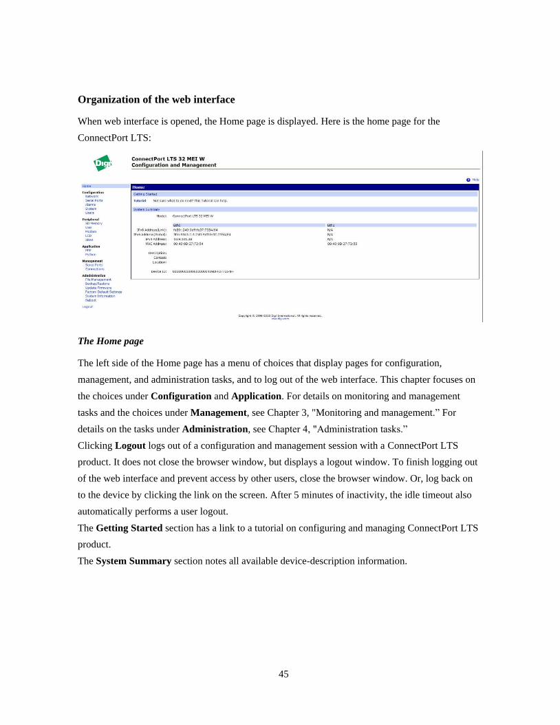
Organization of the web interface
When web interface is opened, the Home page is displayed. Here is the home page for the
ConnectPort LTS:
The Home page
The left side of the Home page has a menu of choices that display pages for configuration,
management, and administration tasks, and to log out of the web interface. This chapter focuses on
the choices under Configuration and Application. For details on monitoring and management
tasks and the choices under Management, see Chapter 3, "Monitoring and management.‖ For
details on the tasks under Administration, see Chapter 4, "Administration tasks.‖
Clicking Logout logs out of a configuration and management session with a ConnectPort LTS
product. It does not close the browser window, but displays a logout window. To finish logging out
of the web interface and prevent access by other users, close the browser window. Or, log back on
to the device by clicking the link on the screen. After 5 minutes of inactivity, the idle timeout also
automatically performs a user logout.
The Getting Started section has a link to a tutorial on configuring and managing ConnectPort LTS
product.
The System Summary section notes all available device-description information.
46
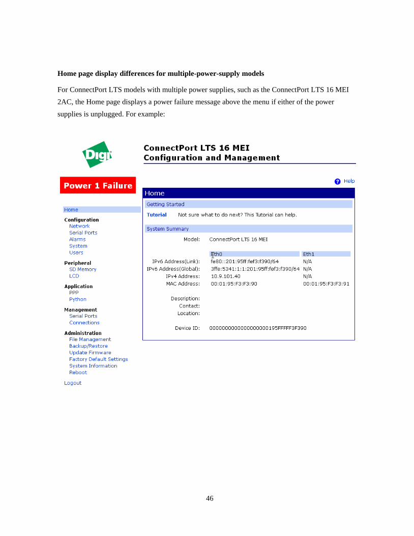
Home page display differences for multiple-power-supply models
For ConnectPort LTS models with multiple power supplies, such as the ConnectPort LTS 16 MEI
2AC, the Home page displays a power failure message above the menu if either of the power
supplies is unplugged. For example:
47
Configuration pages
The choices under Configuration in the menu display pages for configuring settings for various
features, such as network settings, and serial port settings.
Some of the configuration settings are organized on sets of linked screens. For example, the
Network Configuration screen initially displays the IP Settings, and provides links to Network
Services Settings, Advanced Settings, and other network settings appropriate to the ConnectPort
LTS product.
Peripheral pages
The choices under Peripheral display pages for configuring settings for various peripheral devices
on ConnectPort LTS, such as SD memory, USB, Modem, LCD and XBee. (USB, Modem, and
XBee are supported in ConnectPort LTS W versions only)
Application pages
The Application menu item allows for configuring various applications available for use in the
device.
PPP: The PPP application is used to connect incoming clients or serial devices to external
networks using modems and telephony to maintain the connection. The following links will
help to configure this application.
Python: For loading and running custom programs authored in the Python programming
language.
Realport: Configures RealPort settings.
Apply and save changes
The web interface runs locally on the device, which means that the interface always maintains and
displays the latest settings in the ConnectPort LTS product.
On each screen, the Apply button is used to save any changes to the configuration settings to the
ConnectPort LTS product.
Cancel changes
To cancel changes to configuration settings, click the Refresh or Reload button on the web browser.
This causes the browser to reload the page. Any changes made since the last time the Apply button
was clicked are reset to their original values.

48
Restore the ConnectPort LTS product to factory defaults
The device configuration can be reset to factory defaults as needed during the configuration process.
See "Restore a device configuration to factory defaults.‖
Online help
Online help is available for all screens of the web interface, and for common configuration and
administration tasks. There is also tutorial available on the Home page.

49
Change the IP address from the web interface, as needed
Normally, IP addresses are assigned to ConnectPort LTS products through DHCP. This procedure
assumes that the ConnectPort LTS product already has an IP address and you simply want to
change it.
1. Open a web browser and enter the current IP address for the ConnectPort LTS product in the
URL address bar.
2. If security is enabled for the ConnectPort LTS product, a login prompt is displayed. Enter the
user name and password for the device. The default username is root and the default password
is dbps. If these defaults do not work, contact the system administrator who set up the device.
3. Click Network to access the Network Configuration page.
4. On the IP Settings page, select Use the following IP address.
5. Enter an IP address (and other network settings), then click Apply to save the configuration.
50
Network configuration settings
The Network configuration pages include:
Ethernet IP settings: For viewing IP address settings and changing as needed.
Network Services settings: Enable and disables access to various network services, such as
ADDP, RealPort and Encrypted RealPort, Telnet, SSH, HTTP/HTTPS, and other services.
Advanced Network Settings: Configures the Ethernet Interface speed and mode, TCP/IP
settings, TCP keep-alive settings, and DHCP settings.
Alternatives for configuring network communications
There are three ways a ConnectPort LTS product can be configured on the network.
Using dynamic settings: All network settings will be assigned automatically by the network,
using a protocol called DHCP. Contact your network administrator to find out if a DHCP
server is available.
Using static settings: All network settings are set manually and will not change. The IP
address and Subnet Mask are mandatory. The rest are not mandatory, but may be needed for
some functions. Contact your network administrator for the required values.
Using Auto-IP: Auto-IP assigns an IP address to the ConnectPort LTS product immediately
after it is plugged in. If running DHCP or ADDP, the Auto-IP address is overridden and a
network compatible IP address is assigned, or a static IP address can be assigned.
Even if a DHCP server is available, the device configuration may work better with static settings.
Once set, static settings will not change, so you and other network devices can always find the
ConnectPort LTS product by its IP address. With dynamic settings, the DHCP server can change the
IP address. This can happen frequently or infrequently depending on how your network
administrator has configured the network.
When the IP address does change, you and other network devices configured to talk to the
ConnectPort LTS product can no longer access the device. In this case, the ConnectPort LTS
product must be located the Digi Device Discovery utility, and other network devices that need to
communicate with the ConnectPort LTS product must be reconfigured.

51
Ethernet IP settings
The Ethernet IP settings configure how the IP address of the ConnectPort LTS product is obtained,
either by DHCP or by using a static IP address, subnet mask, default gateway. In addition, this page
shows IP addresses of the primary and secondary Domain Name System (DNS) server for the
ConnectPort LTS product. For more information about these settings as assigned and used in your
organization, contact your network administrator. ConnectPort LTS has two Ethernet interfaces and
each interface can be enabled or disabled separately. Each interface has following settings:
IPv4: Internet Protocol version 4 configuration.
Do not use this interface: Choose this option if you do not want to enable IPv4 address on
this Ethernet interface.
Obtain an IP address automatically using DHCP: When the ConnectPort LTS product is
rebooted, it will obtain new network settings.
Use the following IP address: Choose this option to supply static settings. An IP address
and Subnet mask must be entered. Other items are not mandatory, but may be needed for
some functions (such as talking to other networks).
IP Address: An IP address is like a telephone number for a computer. Other network
devices talk to the ConnectPort LTS product using this ID. The IP address is a 4-part ID
assigned to network devices. IP addresses are in the form of 192.168.2.2, where each
number is between 0 and 255.
Subnet Mask: The Subnet Mask is combined with the IP address to determine which
network this ConnectPort LTS product is part of. A common subnet mask is 255.255.255.0.
Gateway: IP address of the computer that enables this ConnectPort LTS product to access
other networks, such as the Internet.

52
IPv6: Internet Protocol version 6 configuration.
Do not use this interface: Choose this option if you do not want to enable IPv6 address on
this Ethernet interface.
Auto configuration: Choose this option if you want to set IPv6 address through the
stateless autoconfiguration protocol.
Obtain an IP address automatically using DHCP: Choose this option if you want to
set IPv6 address through DHCPv6.
Use the following IP address: Choose this option to manually enter static IPv6 address
settings.
IP Address: The IPv6 addresses are normally written as eight groups of four hexadecimal
digits, where each group is separated by a colon (:).
For example, IP v6 addresses are in the form of
2001:0db8:85a3:0000:0000:8a2e:0370:7334
And an IPv6 address must be entered with an IPv6 prefix length of the network. IPv6
network is written in CIDR notation which is separated by a slash "/" to IPv6 address.
For example, an IP v6 address connected to a /64 subnet is written
2001:0db8:85a3:0000:0000:8a2e:0370:7334/64.
Gateway: IP v6 address of the computer that enables this ConnectPort LTS product to
access other networks, such as the Internet.
Use 6to4 tunneling: Choose this option to supply 6to4 Tunneling which consists of
encapsulating IPv6 packets within IPv4; in effect using IPv4 as a link layer for IPv6 so that
the ConnectPort LTS product can reach the remote IPv6 Internet through the existing IPv4
infrastructure.
IPv4 address of the remote 6to4 relay: Set the IPv4 address of the remote 6to4 relay
device.
Overwrite local IPv4 address: Set the public IPv4 address to be used for 6to4 tunneling.
If not set, current IPv4 address of ConnectPort LTS will be used.
DNS: Domain Name Server configuration
Use Manual DNS: Choose this option if you want to set DNS configuration by manual.
Primary DNS: Set the IP address of primary DNS.
Secondary DNS: Set the IP address of secondary DNS.
Source Based Routing: Choose this option to make each network interface use different
router.
53
Basic Network Services Settings
The Basic Network Services page shows a set of common network services that are available for
ConnectPort LTS products, and the network port on which the service is running.
Common network services can be enabled and disabled, and the TCP port on which the network
service listens can be configured. Disabling services may be done for security purposes. That is,
certain services can be disabled so the device runs only those services specifically needed. To
improve device security, non-secure services such as Telnet can be disabled.
It is usually best to use the default network port numbers for these services because they are well
known by most applications.
Several services have a setting for whether TCP keep-alives will be sent for the network services.
TCP keep-alives can be configured in more detail on the Advanced Network Settings page.
Caution Exercise caution in enabling and disabling network services, particularly disabling them.
Changing certain settings can render a Digi Connect device inaccessible. For example,
disabling Advanced Digi Discovery Protocol (ADDP) prevents the device from being
discovered on a network, even if it is actually connected. Disabling HTTP and HTTPS
disables access to the web interface. Disabling basic services such as Telnet, Rlogin, etc.
can make the Command-Line interface inaccessible.

54
Supported basic network services and their default network port numbers
In Digi devices that have multiple serial ports, the network port number defaults for various services
are set based on the following formula:
base network port number + serial port number
The default base assumed is 2000. For example, the Telnet Passthrough service is set to network
port 2001 for serial port 1, 2002 for serial port 2, 2003 for serial port 3, etc.
If a network port is changed for a particular service, that is the only network port number that
changes. That change does not carry over to the other network ports. For example, if the network
port number for Telnet Passthrough is changed from 2001 to 3001, that does not mean that the other
network ports will change to 3002, 3003, etc.
There are two types of network services available:
Basic services, which are accessed by connecting to a particular well-known network port.
Passthrough services, in which a particular serial port is set up for a particular type of service.
To use the service, users must both use the correct protocol and specify the correct network port.
For example, assuming default service ports and using a Linux host, here is how a user would
access the SSH and Telnet passthrough services:
#> ssh -l fred digi16 -p 2501
#> telnet digi16 2101

55
The table shows network services, services provided, and the default network port number for each
service.
Service Services provided
Default
network
port
number
Device Discovery, also known as Advanced Digi Discovery Protocol (ADDP)
Discovery of Digi devices on a network. Disabling this service disables use of the Digi Device Discovery utility to locate the device. The network port number for ADDP cannot be changed from its default.
2362
Encrypted (Secure) RealPort
Secure Ethernet connections between COM or TTY ports and device servers or terminal servers.
1027
Line Printer Daemon (LPD)
Allows network printing over a serial port. 515
Modem Emulation Pool (pmodem)
Allows the ConnectPort LTS product to emulate a modem. Modem emulation sends and receives modem responses to the serial device over the Ethernet instead of Public Switched Telephone Network (PSTN). Telnet processing can be enabled or disabled on the incoming and outgoing modem-emulation connections. The pmodem service is for connecting to whatever serial port will answer.
50000
Modem Emulation Passthrough
Allows the ConnectPort LTS product to emulate a modem. This service is for dialing in to a particular serial port that has been set up for modem emulation.
50001
RealPort A virtual connection to serial devices, no matter where they reside on the network.
771
Remote login (Rlogin) Allows users to log in to the ConnectPort LTS product and access the command-line interface through Rlogin.
513
Remote shell (Rsh) Allows users to log in to the ConnectPort LTS product and access the command-line interface through Rsh.
514
Secure Shell (SSH) Allows users secure access to log in to the ConnectPort LTS product and access the command-line interface.
22
Secure Shell (SSH) Passthrough
Accessing a specific serial port set up for SSH. 2501
Secure Socket Passthrough
Allows an encrypted raw socket connection (using SSL) directly to the serial port.
2601
Simple Network Management Protocol (SNMP)
Managing and monitoring the ConnectPort LTS product. To run SNMP in a more secure manner, note that SNMP allows for set commands to be disabled. This securing is done in SNMP itself, not through this command. If disabled, SNMP services such as traps and device information are not used.
161

56
Service Services provided
Default
network
port
number
Telnet Server Allows users an interactive Telnet session to the ConnectPort LTS product command-line interface. If disabled, users cannot Telnet to the device.
23
Telnet Passthrough Allows a Telnet connection directly to the serial port, often referred to as reverse Telnet.
2001
Transmission Control Protocol (TCP) Echo
Used for testing the ability to send and receive over a TCP connection, similar to a ping.
7
Transmission Control Protocol (TCP) Passthrough
Allows a raw socket connection directly to the serial port, often referred to as reverse sockets.
2101
User Datagram Protocol (UDP) Echo
Used for testing the ability to send and receive over a UDP connection, similar to a ping
7
User Datagram Protocol (UDP) Passthrough
Allows raw data to be passed between the serial port and UDP datagrams on the network.
2101
Web Server, also known as HyperText Transfer Protocol (HTTP)
Access to web pages for configuration that can be secured by requiring a user login. HTTP and HTTPS, below, are also referred to as Web Server or Secure Web Server. These services control the use of the web interface. If HTTP and HTTPS are disabled, device users cannot use the web interface or Java applet to configure, monitor, and administer the device.
80
Secure Web Server, also known as HyperText Transfer Protocol over Secure Socket Layer (HTTPS)
Access to web pages for configuration that can be secured by requiring a user login, with encryption for greater security.
443
57
Advanced Network Services Settings
The Advanced Network Services page shows a set of specific network services that are available for
ConnectPort LTS products, and the related settings for the service.
Web Settings:
Login timeout: Idle timeout settings for Web server.
SMTP Settings:
Enable: Enable or disable the SMTP server
SMTP server name: IP address or DNS name of the SMTP server.
SMTP with authentication: Choose this option if your SMTP server can be accessed after
authentication.
SMTP without authentication: Choose this option if your SMTP server can be accessed
without authentication.
POP before SMTP: Choose this option if your SMTP server can be accessed after
successful login to POP service.
SMTP user name: The user name of your SMTP (or POP) server.
SMTP password: The password of your SMTP (or POP) server.
Device mail address: Mail address that will be used as a mail sender.
NFS Settings:
Enable: Enable or disable the NFS service.
NFS server name: IP address or DNS name of the NFS server.
Mounting path on NFS server: Full path name of mounting point on the NFS server.
NFS timeout: Interval in seconds before disconnecting NFS connection when the NFS
server is not responding.
NFS mount retrying interval: Interval in seconds when NFS remounting is tried after
disconnecting NFS connection.
Alert Settings
- Description: Description for this alert that will be sent to the receiver.
- Send E-mail alert to the following recipients for NFS disconnection: Send an
E-mail alert if checked.
- Subject: Title of E-mail alert.
- To: Recipient of E-mail alert.
- CC: Secondary Recipient of E-mail alert.
Send NFS disconnection trap when alarm occurs: Send an SNMP trap if checked.

58
Samba Settings :
Enable: Enable or disable the Samba service.
Samba server name: IP address or DNS name of the Samba server.
Mounting on path Samba server: Full path name of mounting point on the Samba server.
Samba timeout: Interval in seconds before disconnecting Samba connection when the
Samba server is not responding.
Samba mount retrying interval: Interval in seconds when Samba remounting is tried after
disconnecting the Samba connection.
Alert Settings
- Description: Description for this alert which will be sent to receiver.
- Send E-mail alert to the following recipients for Samba disconnection: Send e-
mail alert if checked.
Subject: Title of E-mail alert.
To: Recipient of E-mail alert.
CC: Secondary Recipient of E-mail Alert.
Send Samba disconnection trap when alarm occurs: Send an SNMP trap if checked.
SYSLOG settings :
Enable: Enable or disable the SYSLOG service.
SYSLOG server name: IP address or DNS name of the SYSLOG server.
SYSLOG facility: Facility level of SYSLOG message.

59
Socket tunnel settings
A Socket Tunnel can be used to connect two network devices: one on the ConnectPort LTS
product’s local network and the other on the remote network. This is especially useful for providing
SSL data protection when the local devices do not support the SSL protocol. One of the endpoint
devices is configured to initiate the socket tunnel. The tunnel is initiated when that device opens a
TCP socket to the ConnectPort LTS product on the configured port number. The ConnectPort LTS
product then opens a separate connection to the specified destination host. Once the tunnel is
established, the ConnectPort LTS product acts as a proxy for the data between the remote network
socket and the local network socket, regardless of which end initiated the tunnel.
Socket Tunnel settings include:
Enable: Enables or disables the configured socket tunnel.
Timeout: The timeout (specified in seconds) controls how long the tunnel will remain
connected when there is no tunnel traffic. If the timeout value is zero, then no timeout is in
effect and the tunnel will stay up until some other event causes it to close.
Initiating Host: The hostname or IP address of the network device which will initiate the
tunnel. This field is optional.
Initiating Port: Specify the port number that the ConnectPort LTS product will use to listen for
the initial tunnel connection.
Initiating Protocol: The protocol used between the device that initiates the tunnel and the
ConnectPort LTS product. Currently, TCP and SSL are the two supported protocols.
Destination Host: The hostname or IP address of the destination network device.
Destination Port: Specify the port number that the ConnectPort LTS product will use to make
a connection to the destination device.
Destination Protocol: This is the protocol used between ConnectPort LTS product and the
destination device. Currently, TCP and SSL are the two supported protocols. This protocol does
not need to be the same for both connections.

60
Advanced network settings
The Advanced Network Settings are used to further define the network interface, including:
Host name: The Host name to be placed in the DHCP Option 12 field. This is an optional
setting which is only used when DHCP is enabled.
Enable Auto IP address assignment: Whether Auto-IP address assignment is enabled or
disabled.
Reuse old IP at bootup time on DHCP failure: Whether the action to reuse the previously
established IP address at bootup time after a DHCP failure is enabled or disabled.
TCP keep-alive settings: The DHCP server assigns these network settings, unless they are
manually set here. To manually set and override these settings, select Ignore TCP Keep-Alive
settings from DHCP and specify the values for Idle Timeout, Probe Interval, and whether an
extra byte should be stored in TCP keep-alive packets.
Ethernet interface: The speed and duplex mode of each Ethernet interface can be set here. The
speed of the Ethernet interface can be set to Auto, 10 Mbit, 100 Mbit, or 1000 Mbit. The
duplex mode of the Ethernet interface can be set to Auto, Half-duplex, or Full-duplex. Note
that the duplex mode cannot be set manually if the speed is set to Auto.

61
Serial port settings
Use the Serial Port Configuration page to establish a port profile for the serial port of the
ConnectPort LTS product. This page includes the currently selected port profile for the serial port,
detailed configuration settings for the serial port, dependent on the port profile selected, and links to
Basic Serial Settings and Advanced Serial Settings.
About port profiles
Port profiles simplify serial port configuration by displaying only those items that are relevant to the
currently selected profile.
There are several port profile choices, but not all port profiles are supported in all products.
Support of port profiles varies by Digi product. If a profile listed in this description is not available
on the page, it is not supported in the Digi product.
If a port profile has already been selected, it is shown at the top of the screen. The profile can be
Changed, or retained, but individual settings adjusted.
Everything displayed on the Serial Port Configuration page, between Port Profile Settings and
the links to the Basic Serial Settings and Advanced Serial Settings, depends on the port profile
selected.
Select and configure a port profile
1. To configure any profile, select Serial Ports.
2. Click the port to be configured.
3. Click Change Profile.
4. Select the appropriate profile and Click Apply.
5. Enter the appropriate parameters for each profile. Descriptions of each profile follow. See also
the online help for the configuration screens for more details about settings and values.
6. Click Apply to save the settings.
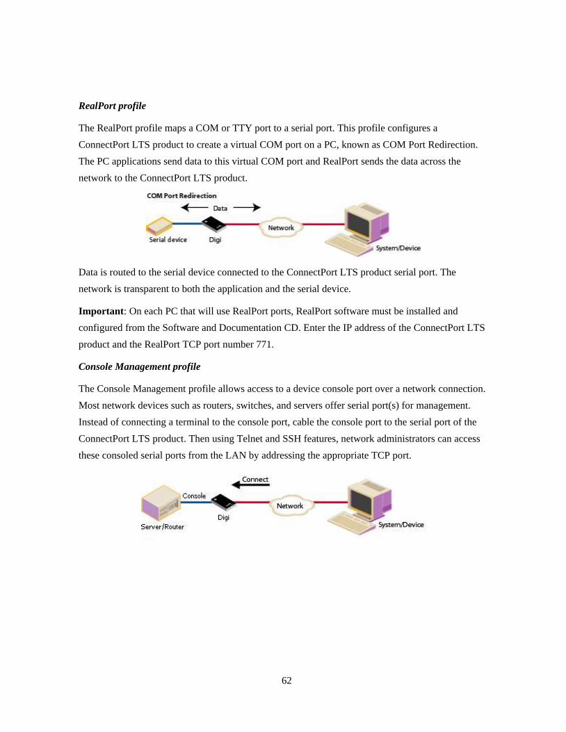
62
RealPort profile
The RealPort profile maps a COM or TTY port to a serial port. This profile configures a
ConnectPort LTS product to create a virtual COM port on a PC, known as COM Port Redirection.
The PC applications send data to this virtual COM port and RealPort sends the data across the
network to the ConnectPort LTS product.
Data is routed to the serial device connected to the ConnectPort LTS product serial port. The
network is transparent to both the application and the serial device.
Important: On each PC that will use RealPort ports, RealPort software must be installed and
configured from the Software and Documentation CD. Enter the IP address of the ConnectPort LTS
product and the RealPort TCP port number 771.
Console Management profile
The Console Management profile allows access to a device console port over a network connection.
Most network devices such as routers, switches, and servers offer serial port(s) for management.
Instead of connecting a terminal to the console port, cable the console port to the serial port of the
ConnectPort LTS product. Then using Telnet and SSH features, network administrators can access
these consoled serial ports from the LAN by addressing the appropriate TCP port.
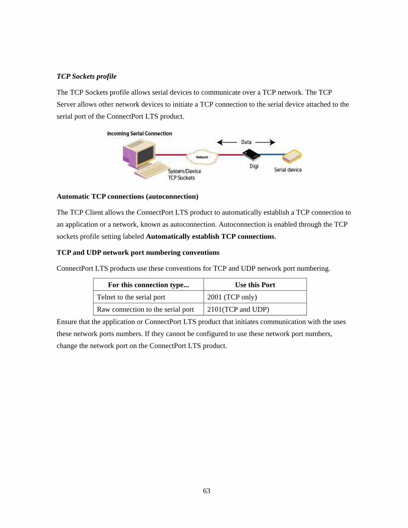
63
TCP Sockets profile
The TCP Sockets profile allows serial devices to communicate over a TCP network. The TCP
Server allows other network devices to initiate a TCP connection to the serial device attached to the
serial port of the ConnectPort LTS product.
Automatic TCP connections (autoconnection)
The TCP Client allows the ConnectPort LTS product to automatically establish a TCP connection to
an application or a network, known as autoconnection. Autoconnection is enabled through the TCP
sockets profile setting labeled Automatically establish TCP connections.
TCP and UDP network port numbering conventions
ConnectPort LTS products use these conventions for TCP and UDP network port numbering.
For this connection type... Use this Port
Telnet to the serial port 2001 (TCP only)
Raw connection to the serial port 2101(TCP and UDP)
Ensure that the application or ConnectPort LTS product that initiates communication with the uses
these network ports numbers. If they cannot be configured to use these network port numbers,
change the network port on the ConnectPort LTS product.
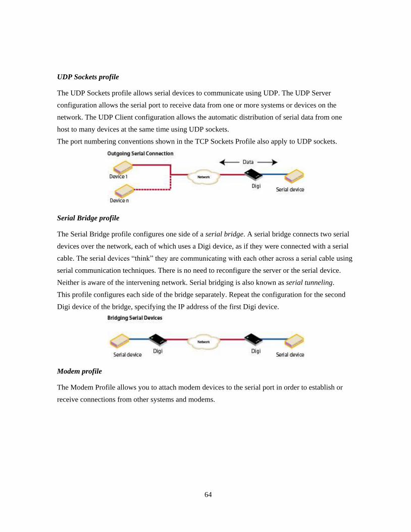
64
UDP Sockets profile
The UDP Sockets profile allows serial devices to communicate using UDP. The UDP Server
configuration allows the serial port to receive data from one or more systems or devices on the
network. The UDP Client configuration allows the automatic distribution of serial data from one
host to many devices at the same time using UDP sockets.
The port numbering conventions shown in the TCP Sockets Profile also apply to UDP sockets.
Serial Bridge profile
The Serial Bridge profile configures one side of a serial bridge. A serial bridge connects two serial
devices over the network, each of which uses a Digi device, as if they were connected with a serial
cable. The serial devices ―think‖ they are communicating with each other across a serial cable using
serial communication techniques. There is no need to reconfigure the server or the serial device.
Neither is aware of the intervening network. Serial bridging is also known as serial tunneling.
This profile configures each side of the bridge separately. Repeat the configuration for the second
Digi device of the bridge, specifying the IP address of the first Digi device.
Modem profile
The Modem Profile allows you to attach modem devices to the serial port in order to establish or
receive connections from other systems and modems.
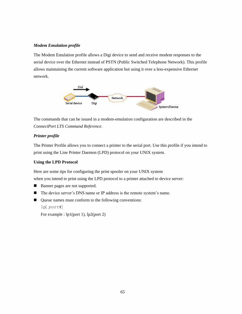
65
Modem Emulation profile
The Modem Emulation profile allows a Digi device to send and receive modem responses to the
serial device over the Ethernet instead of PSTN (Public Switched Telephone Network). This profile
allows maintaining the current software application but using it over a less-expensive Ethernet
network.
The commands that can be issued in a modem-emulation configuration are described in the
ConnectPort LTS Command Reference.
Printer profile
The Printer Profile allows you to connect a printer to the serial port. Use this profile if you intend to
print using the Line Printer Daemon (LPD) protocol on your UNIX system.
Using the LPD Protocol
Here are some tips for configuring the print spooler on your UNIX system
when you intend to print using the LPD protocol to a printer attached to device server:
Banner pages are not supported.
The device server’s DNS name or IP address is the remote system’s name.
Queue names must conform to the following conventions:
lp[port#]
For example : lp1(port 1), lp2(port 2)

66
Local Configuration profile
The Local Configuration profile allows access to the command-line interface when connecting from
a serial terminal.
Custom Profile
The Custom port profile displays all serial-port settings, which can be changed as needed. Use the
Custom profile only if the use of the serial port does not fit into any of the predefined port profiles,
for example, if network connections involve a mix of TCP and UDP sockets. In ConnectPort LTS,
the Custom profile also allows the access of a serial port through RealPort protocol.

67
Basic serial settings
After selecting a port profile, the profile settings are displayed. Choose the appropriate features for
your environment. Here are brief descriptions of the fields in the Basic Serial Settings; see the
online help for detailed information about each setting.
The Description field specifies an optional character string for the port which can be used to
identify the device connected to the port.
Basic Serial Settings include MEI Type, Baud Rate, Data Bits, Parity, Stop Bits, and
Flow Control. MEI (multi-electronic interface) Type sets the type of serial interface if the
ConnectPort LTS is MEI version. The MEI version has three kinds of serial interfaces: RS232,
RS422/485Full, and RS485Half. If the ConnectPort LTS is not the MEI version, MEI Type will
be fixed to RS232 and you cannot change it. Other basic serial port settings must match the
serial settings of the connected device. If you do not know these settings, consult the
documentation that came with your serial device. These serial settings may be documented as
9600 8N1, which means that the device is using a baud rate of 9600 bits per second, 8 data bits,
no parity, and 1 stop bit.
When using RealPort (COM port redirection), these settings are supplied by applications
running on the PC or server, and the default values on the ConnectPort LTS product do not need
to be changed.

68
Advanced serial settings
The advanced serial settings further define the serial interface, including whether port buffering
(also known as port logging), or RTS Toggle are enabled, as general serial interface options. You
can also define how specific aspects of TCP and UDP serial communications should operate,
including timeouts and whether a socket ID is sent.
Serial Settings
The Serial Settings part of the page includes these options:
Enable Port Logging: Enables the port-buffering feature, which allows you to monitor
incoming ASCII serial data in log form. The Log Size field specifies the size of the buffer that
contains the log of ASCII serial data. The Automatic backup option specifies the storage
location of port log and the automatic backup size specifies its size. The SYSLOG service
option enables to send port log to the SYSLOG server specified on Network configuration ->
Network service settings -> Advanced network services settings -> SYSLOG service
settings.
Enable RTS Toggle: When enabled, the RTS (Request to Send) signal is forced high (on) when
sending data on the serial port.
Enable DCD on 8-pin RJ45 connectors (Altpin): When enabled, the functions of DCD pin
and DSR pin are swapped so that eight-wire RJ-45 cables can be used with modems

69
TCP settings
The TCP Settings are displayed only when the current serial port is configured with the TCP
Sockets or the Custom Profile. The settings are as follows:
Send Socket ID: Include an optional identifier string with the data sent over the network. The
Socket ID can be 1 to 256 ASCII characters. To enter non-printable characters, use these key
sequences:
Character Key Sequence
backspace \b
formfeed \f
tab \t
new line \n
return \r
backlash \\
hexadecimal values \xhh
Send data only under any of the following conditions: Enable if it is required to set
conditions on whether the ConnectPort LTS product sends the data read from the serial port to
the TCP destination. Conditions include:
Send when data is present on the serial line: Send the data to the network destinations
when a specific string of characters is detected in the serial data. Enter the string 1 to 4
characters in the Match String field. To enter non-printable characters, use these key
sequences:
Character Key Sequence
hexadecimal values \xhh
tab \t
linefeed \n
backspace \b
Strip match string before sending: Match string before sending to strip the string from
the data before it is sent to the destination.

70
Send after the following number of idle: Send the data after the specified number of
milliseconds has passed with no additional data received on the serial port. This can be 1
to 65,535 milliseconds.
Send after the following number of bytes: Send the data after the specified number of
bytes has been received on the serial port. This can be 1 to 65,535 bytes.
Close connection after the following number of idle seconds: Enable to close an idle
connection. Use the Timeout field to enter the number of seconds that the connection will be
idle before it is closed. This can be 1 to 65000 seconds.
Close connection when DCD goes low: When selected, the connection will be closed when
the DCD (Data Carrier Detected) signal goes low.
Close connection when DSR goes low: When selected, the connection will be closed when the
DSR (Data Set Ready) signal goes low.
UDP settings
The UDP Settings are displayed only when the current serial port is configured with the UDP
Sockets or the Custom Profile.
Send Socket ID: Include an optional identifier string with the data sent over the network. The
Socket ID can be 1 to 256 ASCII characters. To enter non-printable characters, use these key
sequences:
Character Key Sequence
backspace \b
formfeed \f
tab \t
new line \n
return \r
backlash \\
hexadecimal values \xhh
71
Authentication Settings
The authentication settings set the authentication method and related settings. The ConnectPort LTS
supports following authentication methods.
None: When selected, user can access the serial port without authentication. This is the factory
default setting.
Local: When selected, the user who registered the local database of ConnectPort LTS through
user configuration can only access the serial port.
Radius: When selected, the user who registered the database of the specified Radius server can
access the serial port only. The Radius authentication method can be further divided into
following four categories:
Radius server: User authentication is performed only through the Radius server.
Radius server - Local: User authentication is performed through the Radius server first. If
authentication succeeds, the user can access the serial port. If authentication fails, user
authentication is performed through the local database of ConnectPort LTS again.
Local - Radius server: User authentication is performed through the local database of
ConnectPort LTS first. If authentication succeeds, user can access the serial port. If
authentication fails, user authentication is performed through the Radius server again.
Radius down - Local: User authentication is performed through the Radius server first. If
authentication succeeds, user can access the serial port. If the Radius server does not
respond to the authentication request from the ConnectPort LTS, user authentication is
performed through local database of ConnectPort LTS again. If the authentication through
the Radius server is failed, authentication through local database of ConnectPort LTS is not
performed and the user cannot access the serial port.

72
For Radius authentication, the following settings are required.
Primary authentication server: The IP address or DNS name of authentication server.
This option is compulsory to use the remote authentication method. If this server is down
or busy, the authentication query is sent to the secondary server, if specified.
Secondary authentication server: The IP address or DNS name of the secondary
authentication server. This option is complementary.
Authentication server socket: The TCP port to use for authentication communication.
The default port number for Radius authentication is 1812. The primary and the secondary
servers are required to use the same TCP port.
Primary accounting server: The IP address or DNS name of accounting server. This
option can be specified only when user accounting is required. If this server is down or
busy, the accounting information is sent to the secondary server, if specified.
Account server socket: The TCP port to use for accounting communication. The default
port number for Radius accounting is 1813. The primary and secondary servers are
required to use the same TCP port.
Shared secret: A kind of password used for encryption of messages between the
authentication server and the ConnectPort LTS. The server and device server must use the
same secret. The primary and the secondary servers are required to use the same secret.
Timeout: The length of time, in seconds, the ConnectPort LTS will wait for the response
from authentication server before timing out.
Retries: The retries controls how many time the ConnectPort LTS will try to communicate
with the authentication server.
The following settings are optional:
Secondary accounting server: The IP address or DNS name of the secondary accounting
server.

73
LDAP: When selected, user who registered the database of LDAP server specified can
only access the serial port. There are several categories of LDAP authentication Methods:
LDAP server: The user authentication performed only through the LDAP server.
LDAP server - Local: The user authentication performed through the LDAP server
first. If succeeded, user can access the serial port. If failed, user authentication
performed through local database of ConnectPort LTS again.
Local - LDAP server: The user authentication performed through the local database
of ConnectPort LTS first. If authentication succeeds, user can access the serial port. If
authentication fails, user authentication is performed through the LDAP server again.
LDAP down - Local: The user authentication performed through the LDAP server
first. If succeeded, user can access the serial port. But if the LDAP server does not
respond to the authentication request from the ConnectPort LTS, user authentication
performed through local database of ConnectPort LTS again. But if the authentication
through the LDAP server is failed, authentication through local database of
ConnectPort LTS is not performed and the user cannot access the serial port.
For LDAP authentication, the following settings are required:
Primary authentication server: The IP address or DNS name of authentication server.
This option is compulsory to use the remote authentication method. If this server is
down or busy, the authentication query is sent to the secondary server (if it is specified)
Authentication server socket: The TCP port to use for authentication communication.
The default port number for LDAP authentication is 389. The primary and the
secondary servers are required to use the same TCP port.
LDAP search base: LDAP search base (the distinguished name of the search base
object) defines the location in the directory from which the LDAP search begins.
Domain name for active directory: If the LDAP database resides on a Microsoft
system, the Domain name for the active directory must be configured on this option. If
using a non-Microsoft system, do not use this setting, as it changes the LDAP to
comply with Microsoft syntax.
Secure LDAP: If StartTLS is selected, the StartTLS extended operation is used to
secure the communication between ConnectPort LTS and the LDAP Server.
The following settings are optional:
Secondary authentication server: The IP address or DNS name of the secondary
authentication server.

74
Port group settings
As a convenience feature, port groups can be created to send data to multiple ports. Instead of
sending data to individual serial ports, data can be sent to all ports in a group simultaneously
through a port in a group. If you select an additional option, you can also see the data from multiple
ports in the same group from a terminal connected to the one of serial ports in the group.
To configure a port group, you must create a port group first and then select ports to be associated
with this group. Maximum number of port group you can create is 16 and a port cannot be
associated with multiple groups. When you select ports to be associated with a group you can also
configure following settings.
Show data from all ports associated with same port group: When selected, user can see the
data from other ports in the same group from a terminal connected to the one of serial ports in
the group. You can control the pattern of data from other ports in the same group.
Send after the following number of bytes: Send the data to the other ports in the same
group after the specified number of bytes has been received on the serial port. This can be 1
to 4096 bytes. Default is 1024 bytes.
Send after the following number of idle milliseconds: Send the data to the other ports in
the same group after the specified number of idle time has been passed with no additional
data received on the serial port. This can be 1 to 65,535 milliseconds. Default is 1000
milliseconds.

75
Alarms
Use the Alarms page to configure device alarms or display current alarms settings. Device alarms
are used to send email messages or SNMP traps when certain device events occur. These events
include and certain data patterns being detected in the data stream.
Alarm notification settings
On the Alarms page, the Alarm Notification Settings control the following:
Enable alarm notifications: Enables or disables all alarm processing for the Digi Connect
device.
Alarm conditions
The Alarm Conditions part of the Alarms page shows a list of all of the alarms. Up to 32 alarms can
be configured, and they can be enabled and disabled individually.
Alarm list
The list of alarms displays the current status of each alarm. If there are any alarms already
configured for the device, and after configuring any new alarms, this list can be used to list to view
alarm status at a glance, then view more details for each alarm as needed.
Enable: Checkbox indicates whether the alarm is currently enabled or disabled.
Alarm: The number of the alarm.
Type: The basis for the alarm; whether it is based on serial data pattern matching.
Trigger: The conditions that trigger the alarm.
SNMP Trap: Indicates whether the alarm is sent as an SNMP trap.
If the SNMP Trap field is disabled, and the Send To field has a value, then the alarm is sent as
an email message only.
If the SNMP trap field is enabled and the Send To field is blank, then the alarm is sent as an
SNMP trap only.
If the SNMP Trap field is enabled, and a value is specified in the Send to field, then that means
the alarm is sent both as an email and as a SNMP trap.
Send To: The email address to which the alarm is sent.
Email Subject: The text to be included in the ―Subject:‖ line of any alarms sent as email
messages.

76
Alarm conditions
To configure an alarm, click on it. The configuration page for individual alarms has two sections:
Alarm Conditions: For specifying the conditions on which the alarm is based, such as serial
data pattern matching or data usage.
Alarm Destinations: For specifying how the alarm is sent, either as an email message or an
SNMP trap, or both, and where the alarm is sent.
Alarm conditions
The Alarm Conditions part of the page is for specifying the conditions on which the alarm is based.
Alarm conditions include:
Send alarms based on serial data pattern matching: Click this radio button to specify that
this alarm is sent when the specified serial data pattern is detected. Then specify the following:
Serial Port: The serial port to monitor for the data pattern. This field is displayed for devices
where more than one serial port is available.
Pattern: An alarm is sent when the serial port receives this data pattern. Special characters such
as carriage return carriage return (\r) and new line (\n) in the data pattern can be included.
Alarm destinations
The Alarm Destination part of the page defines how alarm notifications are sent—either as an email
message or an SNMP trap, or both—and where the alarm notification is sent.
Alarm Type: Specify the alarm type to be sent. [none|email|snmptrap|all]
Alarm Description: The text to be included in the Subject: line of the alarm-notification email
or SNMP traps description.
To: The email address to which this alarm notification email message will be sent.
CC: The email address to which a copy of this alarm notification email message will be sent
(optional).
Priority: The priority of the alarm notification email message.
Send SNMP trap to the following destination when alarm occurs: If the Alarm Type is set
as snmptrap or all and if the Enable Simple Network Management Protocol (SNMP) trap option
is enabled on the Simple Network Management Protocol (SNMP) Settings of System
Configuration, then the IP address of the destination for the SNMP traps will be displayed as
the destination on this section automatically.
Click Apply to apply changes for the alarm and return to the Alarms Configuration page.

77
Enable and Disable Alarms
Once alarm conditions are configured, enable and disable individual alarms by selecting or
deselecting the Enable checkbox for each alarm.
System settings
The System Configuration page configures system settings, including device description
information, such as the device name, contact, and location, and whether SNMP is enabled or
disabled and the SNMP traps that are enabled.
Device Identity Settings
A device identity is a system description of the ConnectPort LTS product description, contact, and
location. This device identity can be useful for identifying a specific Digi device when working
with a large number of devices in multiple locations.
The Device ID is a numeric identifier for the ConnectPort LTS product. This identifier should be
unique for each Digi device being located on the network.
78
SNMP configuration settings
Simple Network Management Protocol (SNMP) is a protocol that can be used to manage and
monitor network devices. ConnectPort LTS products can be configured to use SNMP features, or
SNMP can be disabled entirely for security reasons. To configure SNMP settings, click the Simple
Network Management Protocol link at the middle of the System Configuration page. SNMP
settings include:
Enable Simple Network Management Protocol (SNMP) v1/v2c: This checkbox enables or
disables use of SNMP version 1 or version2c.
The SNMPv1/v2c Get community and SNMPv1/v2c Set community fields specify passwords
required to get or set SNMP-managed objects. Changing get and set community names from
their defaults is recommended to prevent unauthorized access to the device.
SNMPv1/v2c Get community: The password required to get SNMP-managed objects. The
default is public.
SNMPv1/v2c Set community: The password required to set SNMP-managed objects. The
default is private.
SNMPv1/v2c Permission: Allow SNMP clients to set device settings through SNMP:
get only: Disables the capability for users to issue SNMP set commands uses use of SNMP
read-only for the ConnectPort LTS product.
get/set: Enables the capability for users to issue SNMP set commands uses use of SNMP
read-only for the ConnectPort LTS product.
Enable Simple Network Management Protocol (SNMP) v3: Enables or disables use of
SNMP version 3.
User: The user name that is authenticated to communicate with the SNMP engine.
Security level: The security level of the user with regard to authentication and privacy:
Auth_NoPriv or Auth_Priv.
Authentication protocol: The authentication protocol algorithm to be used: MD5 or SHA.
Authentication password/ Authentication password (confirm): Supply and confirm the
password for the user.
Privacy protocol: The privacy protocol to be used: DES or AES.
Privacy password/ Privacy password (confirm): Supply and confirm the password for the
user.
SNMPv3 Permission: Select the appropriate permission level: get only or get/set.
79
Enable Simple Network Management Protocol (SNMP) traps: Enables or disables the
generation of SNMP traps.
Trap version: SNMP version for the trap
Trap primary IP: The primary IP address of the system to which traps are sent. In order to
enable any of the traps, a non-zero value must be specified. For ConnectPort LTS products
that support alarms, this field is required in order for alarms to be sent in the form of SNMP
traps. See "Alarms.‖
Trap secondary IP: The secondary IP address of the system to which traps are sent.
Trap community: Community string for SNMP trap.
Trap user: Enter the user name that is authenticated to communicate with the SNMP v3
trap engine.
Trap security level: The security level of the user with regard to authentication and
privacy in case of SNMPv3 trap: Auth_NoPriv or Auth_Priv.
Trap authentication protocol: The authentication protocol algorithm to be used for
SNMPv3 trap: MD5 or SHA.
Trap authentication password/ Trap authentication password (confirm): Supply and
confirm the password for the user in case of SNMPv3 trap.
Trap privacy protocol: The privacy protocol to be used for SNMPv3 trap: DES or AES
Trap privacy password/ Trap privacy password (confirm): Supply and confirm the
password for the user in case of SNMP v3 trap.
Trap engine ID: The SNMP v3 engine ID of trap receiver.
At the bottom of the page are checkboxes for the SNMP traps that can be used:
authentication failure, login, cold start, and link up traps.

80
Date and Time Settings
System Date and Time can be changed on this configuration page.
Authentication Settings
The authentication settings for system set the authentication method and related settings of Web UI
and CLI access. CLI access includes CLI access through serial console, telnet, SSH, Rlogin and Rsh.
Remote authentication will use the permissions set to the default "ruser" user.
You can select authentication method for Web UI and CLI access differently and following
authentication methods are supported.
For descriptions of these settings, see ―Authentication Settings’ on page71.

81
User settings
User settings involve several areas:
User authentication: whether authentication is required for users accessing the ConnectPort
LTS product, and the information required to access it. Depending on the Digi product, multiple
users and their authentication information can be defined. User authentication settings are on
the Users settings page.
User access settings: the device interfaces that a user can access, such as the command line or
web interface.
User permissions settings: the permissions a user has to access and configure the Digi Connect
device.
Several settings on the Network Configuration pages are available to further secure the
ConnectPort LTS product. For example, unused network services can be disabled on the
Network Services page.
Multi-user model implemented in ConnectPort LTS
The user model in ConnectPort LTS product influences the commands that users can issue.
ConnectPort LTS supports multiple users. ConnectPort LTS products use a more-than-two-user
model. Up to 32 users can be defined. Characteristics of this model include:
User 1 has a default name of root. This user is also known as the administrative user.
A user named ruser is used to set permissions for users authenticating remotely via RADIUS
and/or LDAP.
Users are defined by the User settings in the web interface or the set user command in the
command-line interface.
User 1 has default permissions that enable it to issue all commands.
Permissions for User 1 can be changed to be less than the default root permissions.
Additional users may be defined as needed.
set user, set group and other commands are described in detail in the ConnectPort LTS
Command Reference. Currently, there is no web interface page for defining user groups.

82
Password authentication
By default, Digi Connect Family devices have password authentication enabled. That means when a
login prompt is displayed when accessing the device by opening the web interface or issuing a
telnet command.
Disable password authentication
In ConnectPort LTS, all users should have a password and password authentication cannot be
disabled.
Change the password for administrative user
To increase security, change the password for the administrative user from its default. By default,
the administrative username is root.
Note Record the new password. If the changed password is lost, the ConnectPort LTS product
must be reset to the default firmware settings.
In Digi devices with a single-user model, changing the root password also changes the password for
Advanced Digi Discovery Protocol (ADDP). In Digi devices with the multi-user model, changing
the root password has no effect on ADDP. To change the ADDP password, enter
newpass name=addp from the command line.
In the web interface:
1. On the Main menu, click Users.
2. On the Users Configuration page, click root.
3. Enter the new password in the New Password and Confirm Password edit boxes. The
password can be from 4 through 16 characters long and is case-sensitive. Click Apply.
4. A logoff is forced immediately. Log in to the web interface using the new values.
From the command line:
Issue a newpass command with a zero-length password.

83
Add users
Digi Connect Family products allow multiple users to be defined. For those products, the Users
Configuration page shows the currently defined users and allows you to add more user definitions.
To add a user definition:
1. On the Main menu, click Users.
2. On the Users Configuration page, click New.
3. On the Add New Users page, specify the user name and password to be used for login. The
password can be from 4 through 16 characters long and is case-sensitive. Confirm the password,
and click Apply. The changes take effect immediately. No logout/login is necessary.
User access settings
For ConnectPort LTS products with the two-user or more-than-two-users model, user access to the
device interfaces is configurable. For example, the administrative user can access both the
command line and web interface, but other users can be restricted to the web interface only.
Take care in changing access settings. If you are logged in as the administrative user and disable
web interface, you will not be able to log in to the ConnectPort LTS product on your next attempt,
and there is no way to raise your user permissions to enable the web interface again. You must reset
the device to factory defaults to enable the web interface access.
To set access settings:
1. On the Main menu, click Users.
2. On the Users Configuration page list of users, click on the user.
3. On the User Access page, enable or disable the device interface access as desired:
– System Interface Access
Shell: Enables or disables access to the shell program of command line interface.
CLI menu: Enables or disables access to the menu program of command line interface.
– Web Interface Access
Allow web interface access: Enables or disables access to the web interface.
4. Click Apply. The changes take effect immediately. No logout/login is necessary.
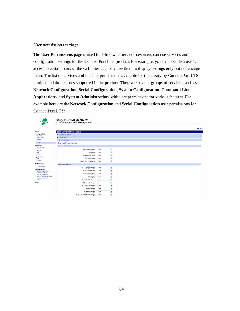
84
User permissions settings
The User Permissions page is used to define whether and how users can use services and
configuration settings for the ConnectPort LTS product. For example, you can disable a user’s
access to certain parts of the web interface, or allow them to display settings only but not change
them. The list of services and the user permissions available for them vary by ConnectPort LTS
product and the features supported in the product. There are several groups of services, such as
Network Configuration, Serial Configuration, System Configuration, Command Line
Applications, and System Administration, with user permissions for various features. For
example here are the Network Configuration and Serial Configuration user permissions for
ConnectPort LTS:

85
User permissions and effects
Permission Setting Effect
None The user does not have permission to execute this setting.
Read Self The user can display his/her own settings, but not those of other users.
Read The user can read the settings for all users, but does not have permission to
modify or write the settings.
Read/Write Self The user can read and write his/her own settings, but not those of other users.
Read All/Write Self The user can read the settings for all users and can modify their own settings.
Read/Write The user has full permission to read and write the settings for all users.
Execute The user has full permission to execute the settings.
Restrictions on setting user permissions
A user cannot set another user's permission level higher than his/her own permission level, nor can a
user raise his/her own permission level.
Set user permissions from the web interface
1. On the Main menu, click Users.
2. On the Users Configuration page list of users, click on the user.
3. Click on User Permissions.
4. A list of feature groupings and the user permissions for them is displayed. Customize these
settings as needed.
5. Click Apply.
Set user permissions from the command-line interface
User permissions can be set from the command-line interface by the set permissions command. See
the ConnectPort LTS Command Reference for the command description.
Disable unused and non-secure network services
To further secure the ConnectPort LTS product, network services not necessary to the device,
particularly non-secure or un-encrypted network services such as Telnet, can be disabled. See
"Network services settings.‖

86
Peripheral
SD Memory
The ConnectPort LTS supports standard SD and SDHC (high-capacity) memory cards. To use an
SD memory device, insert the card to the SD slot and then select Start service on SD Memory
configuration page. Once the SD memory card service is started, you can see the card information
such as Card Type, File system, used size and available size. And you can also format the card
using the Format button on the SD Memory configuration page.
The physical mounting point of SD memory device on the ConnectPort LTS is /mnt/sd.
USB
To use USB device, insert the device to the USB port and then select Start service of the USB
device to be started on USB configuration page. ConnectPort LTS W version has two USB ports.
For the storage type USB device, you can see the device information such as Card Type, File
system, used size and available size after starting the USB service. And you can also format the
USB storage device using the Format button on the USB configuration page.
The physical mounting point of USB device on the ConnectPort LTS is /mnt/usb1 or /mnt/usb2.

87
Modem
ConnectPort LTS W has an internal modem that is configured it on this page. The Modem
configuration page has the same configuration settings of Modem Profile of Serial port settings and
it allows you to establish or receive connections from other systems and internal modems. Modem
configuration page allow you to use the following type of connection
Incoming Connection: Used for dial-in connections, such as inbound PPP connections or to
manage a device through a telephone network. The ConnectPort LTS product server will
receive connections from other hosts.
Outgoing Connection: The modem will dial-out to establish connections with external hosts or
to connect to an external PPP network.
Network Bridge Connection (bi-directional): The modem can be used both to establish
connections to other hosts as well as receive connections from other hosts.
The Modem configuration page also allows you to configure the following settings:
Init String: This is the modem initialization settings. Modify the init string to change the
behavior of the modem as needed by your application.
Note: if the modem is currently in use, the init string change will not take effect immediately. It
will be used the next time the modem is initialized.
Enable PPP Connections on this Modem: If enabled, the modem will be used for PPP
connections. You will need to configure the PPP connection through PPP configuration.
Enable callback: If the callback is enabled, the ConnectPort LTS product disconnects the
connection from a remote site and then calls the phone number specified at the callback phone
number.
Callback phone number: The phone number which the ConnectPort LTS product calls with
callback enabled.
Dial-in modem callback login: The ConnectPort LTS product calls the phone number
specified at the callback phone number after a user authentication.
Allow dial-in modem callback number change: The ConnectPort LTS product will ask a user
whether to change the callback phone number before calling.

88
LCD
ConnectPort LTS has an LCD display and you can configure it on this page. The LCD configuration
page has
Enable display: If checked, LCD display is enabled and you can use LCD menu using keypad.
Background image wait time: Specifies how much user idle time must elapse before the
background image is launched on the LCD display. Default is 0 means the background
image will not be launched automatically.
Use default background image: If checked, default background image will be launched on the
LCD display when either the wait time is elapsed or the Exit menu is selected using keypad on
the LCD display.
Load background image: Used to upload user defined background image on ConnectPort LTS.
This product supports only 128 x 64 8 bit bitmap image. If incorrect type of image is uploaded,
error message will be displayed on LCD screen. After uploading user image, the Enable
display or Use default background image option should be toggled once to force the LCD
daemon to reload the image.
Load custom (python) program: Used for uploading Python programs onto the ConnectPort
LTS.
For detailed instructions for configuring an IP address using the LCD interface, please see
―LCD interface: configuration, monitoring, and diagnostics‖ on page 131.

89
XBee
The XBee configuration page has very similar settings to the Custom serial port profile. Once
Allow direct access from networks is checked, you can access the XBee port in the same manner
that is used to access a serial port in custom profile. The default setting for Allow direct access
from networks is Disabled.
For detailed information about XBee RF modules and commands for configuring them, please refer
to the Product Manual: XBee / XBee-PRO ZB OEM RF Modules.

90
Applications
Additional configurable applications are accessed from the main menu under Applications. Some
devices have an Applications link under Configuration.
Python® program management
Digi incorporates a Python development environment into ConnectPort LTS products. Python is a
dynamic, object-oriented language that can be used for developing a wide range of software
applications, from simple programs to more complex embedded applications. It includes extensive
libraries and works well with other languages. A true open-source language, Python runs on a wide
range of operating systems, such as Windows, Linux/Unix, Mac OS X, OS/2, Amiga, Palm
Handhelds, and Nokia mobile phones. Python has also been ported to Java and .NET virtual
machines. Unlike proprietary embedded development platforms, Digi's integration of the universal
Python programming language allows customers a truly open standard for complete control of
connections to devices, the manipulation of data, and event based actions.
Recommended distribution of Python interpreter
The current version of the Python interpreter embedded in the ConnectPort LTS is 2.6.2. Please use
modules known to be compatible with this version of the Python language only.
Software development resources
Digi provides several resources to help you get started developing software solutions in Python:
Digi Python Programming Guide
This guide introduces the Python programming language by showing how to create and run a simple
Python program. It reviews Python modules, particularly modules with Digi-specific behavior. It
describes how to load and run Python programs onto Digi devices, either through the command-line
or web user interfaces, and how to run several sample Python programs. Find this guide at the Digi
Python Wiki page--in the Start Here section, click the link titled
Digi Python Programmer's Guide http://www.digi.com/wiki/developer/index.php/Python_Wiki
General Python programming language is available at http://www.python.org/
Click the Documentation link.

91
Digi Developer Community Wiki:
The Digi Developer Community Wiki is a place to learn about developing solutions using Digi’s
software and services, including Python, iDigi Platform, iDigi Dia, and more.
http://www.digi.com/wiki/developer/index.php/Main_Page
Digi Python Custom Development Environment page
Python functions can be used to obtain data from attached and integrated sensors on Digi products
that have embedded XBee RF modules, such as the Drop-in Networking Accessories. The Digi
Python Custom Development Environment page is an access point: for such information.
http://www.digi.com/technology/drop-in-networking/python.jsp
Python Support Forum on digi.com
Find answers to common questions and exchange ideas and examples with other members of the
Digi Python development community at:
http://www.digi.com/support/forum/forum.jspa?forumID=104
Python configuration pages
Selecting Applications > Python from the main menu for a Python-enabled ConnectPort LTS
product displays the Python Configuration pages. These pages are used to manage Python program
files including uploading them to ConnectPort LTS products and deleting them as needed, and
configure Python programs to execute when the ConnectPort LTS product boots, also known as
auto-start programs.
Python files
The Python Files page is for uploading and managing Python programs on a ConnectPort LTS
product.
Upload Files: Click Browse to select a file to upload to and click Upload.
Manage Files: Select any files to remove from the ConnectPort LTS product and click Delete.

92
Auto-start settings
The Auto-start Settings page configures Python programs to execute when the ConnectPort LTS
product boots.
Up to four auto-start programs can be configured.
Enable: When checked, the program specified in the Auto-start command line field will be run
when the device boots.
Auto-start command line: Specify the Python program filename to be executed and any
arguments to pass to the program. The syntax is as follows, where arg1 and arg2 are program
arguments:
filename [arg1 arg2...]
Manually execute uploaded Python programs
To manually execute an uploaded Python program on a ConnectPort LTS product, access the
command line of
the device and enter the command:
python filename [arg1 arg2...]
View and manage executing Python programs
To view Python threads running on the ConnectPort LTS product, access the command line and
enter the who
command.

93
PPP configuration
PPP (Point-to-point Protocol) provides TCP/IP communication over a modem connected to a serial
port on your ConnectPort LTS server. PPP allows you to connect a device to a network using a
telephone line and that device has access to the resources of the network as if it were directly
connected to the network.
Basic PPP settings
Under Basic PPP settings, users can set the PPP (Point-to-Point Protocol) options to enable or
disable the dynamic IP address pool. The dynamic IP address pool is a set of reserved IP addresses
unique to the network that are assigned to the incoming connections. Users set the first IP address to
use and the number of sequential addresses (plus one) to be reserved for assignment
Incoming PPP Connection
Incoming PPP connections are connections where users dial-in to the ConnectPort LTS product.
Users will typically connect using a modem and dial the phone number of the modem connected to
the serial port. Examples of incoming PPP connections are allowing users with a modem to access
the network that the ConnectPort LTS product uses or to create a network bridge by connecting two
separate networks together using modems.

94
Authentication configuration
- User Name: Specifies the username for this connection. The username, along with the
password, are specified by the user when connecting to the device. This username must be
unique to the device so that no other incoming PPP connection, outgoing PPP connection,
or system user uses it.
- Password/Confirm Password: Specifies the password for this connection. This is the
password that the user specifies when connecting and logging into the device.
- Authentication: Specifies the type of authentication required by this PPP connection. The
user must supply the same type of authentication for their dial-up connection as specified
here in order to successfully connect.
NONE: No authentication is required.
CHAP: CHAP (Challenge Handshake Authentication Protocol) provides secure encrypted
authentication. CHAP is used to periodically verify the identity of the peer using a 3-way
handshake. This is done upon initial link establishment and may be repeated anytime after
the link has been established. (See RFC 1334 for further details.) CHAP authentication will
work between two ConnectPort LTS products. Note: MS-CHAP (Microsoft specific
implementation of CHAP) is not supported.
PAP: PAP (Password Authentication Protocol) is used by many ISPs and corporate PPP
servers. PAP provides a simple method for the peer to establish its identity using a 2-way
handshake. This is done only upon link establishment. (See RFC 1334 for further details.)
BOTH: CHAP authentication will work between two ConnectPort LTS products. CHAP
will be negotiated to PAP for all other connections.

95
Peer configuration: Specifies how the remote IP address that is supplied to the client is
assigned.
- Automatically Assign Remote IP Address from IP Address Pool: The remote IP address
will automatically be assigned with a unique address from the IP address pool (as
configured in Basic PPP Settings; see page 93). The assigned address will not conflict with
any other PPP connection using the dynamic IP address pool.
- Note: This option requires the Dynamic IP Address Pool to be enabled.
- Allow remote peer to specify remote IP address: The remote IP address will
automatically be assigned by the remote peer.
- Assign Static Remote IP Address: The remote IP address will be assigned the IP address
configured on the Remote IP Address field. This connection will always be assigned this
same IP address. This is useful if the client needs to have the same IP address if it is
running as a server, for example.
- Allow Client Access to Local Network via PPP Connection: Specifies whether the
remote client should have access to the local Ethernet network when they dial-in to the PPP
connection. This option requires the ConnectPort LTS product to have a unique local IP
address for each PPP connection in order to handle the routing between the PPP connection
and local network.
- Local IP Address Specifies the local IP address to use for the PPP connection. This IP
address must be unique on the network and must not be the same as the remote IP address
or any address in the dynamic IP address pool. This address should reside on a different
subnet than the Ethernet IP address.
Advanced configuration: Specifies how the remote IP address that is supplied to the client is
assigned.
Enable Idle Timeout: Enables or disables whether this connection uses an idle timeout. The
idle timeout specifies the maximum allowed time a connection can remain idle before it is
closed. The idle time is defined as the elapsed time after the last byte that was received by this
connection. If this option is not checked (disabled), then the connection can remain idle for any
amount of time. If this option is checked (enabled), then the connection will be closed after the
connection has been idle for Timeout seconds.
96
Setting up incoming PPP connections
To configure the correct settings for incoming PPP connections, you need to configure settings on
Application -> PPP first and then configure settings on Configuration -> Serial Ports.
Settings on Application -> PPP
Basic PPP Settings:
To assign an IP address for incoming PPP client automatically, check Enable Dynamic IP
Address Pool for Incoming Connections and enter First IP Address and Number of
Addresses.”
Incoming PPP Connections
This section is used to make and maintain rules for incoming PPP connections. To make a new
rule for incoming PPP connections, follow these steps.
1. Click the New connection button.
2. On the Serial Port section of Incoming connection page, select the serial ports that you
want this connection rule to apply.
3. On the Authentication Configuration section, enter the User Name and Password which
will be used for PPP authentication such as NONE/PAP/CHAP/BOTH.
NOTE: To use the Local authentication method for Serial port authentication (See step 15
below), you need to enter the User Name and Password from one of the System users.
If not, you will fail to make a PPP connection, because you cannot specify PPP user on the
Authentication page of the serial port separately.
But if you are going to use None authentication method for Serial port authentication, you
can add any user even if it is not on the local database of system user and you can select
user name from the PPP User menu on the Authentication page of the serial port.
4. Next select the authentication method from one of following methods,
NONE: The remote user does not require PPP authentication.
PAP: Password Authentication Protocol (PAP) authentication is required.
CHAP: Challenge Handshake Authentication Protocol (CHAP) authentication is required.
BOTH: Both CHAP and PAP authentication are required.

97
5. In the Peer Configuration section, select an option for assigning the IP address of
incoming PPP client.
Automatically assign remote IP address from IP address pool: If you select this option,
IP address for incoming PPP client will be automatically assigned from the IP address pool
set on Basic PPP Settings page
Allow remote peer to specify remote IP address: If you select this option, incoming PPP
client will specify the IP address used for this PPP connection.
Assign static remote IP address: If you select this option, IP address for incoming PPP
client will be assigned as specified at Remote IP address
6. In the Peer Configuration section, check Allow client access to local network via PPP
connection if you want the incoming PPP client to be able to access the ConnectPort LTS,
or other devices on the network through the PPP interface of ConnectPort LTS. Once you
enable this option, you can select another option for assigning the IP address of local PPP
interface.
Automatically assign local IP address from IP address pool: The IP address for the local
PPP interface is automatically assigned from the IP address pool set on Basic PPP Settings
page.
Assign static local IP address: The IP address for local PPP interface is assigned as
specified at Local IP address.
7. In the Advanced Configuration section, check Enable idle timeout if you want to close
PPP connection when there is no activity from the incoming PPP client during the time
specified at Timeout (sec).
Advanced PPP Settings:
If you want to the incoming PPP client to be able to access the local network where the
ConnectPort LTS is connected, check the Process ARP Requests (Proxy ARP) option.
98
Settings on Serial ports
1. Select a port from Configuration -> Serial ports -> Ports Settings
2. Change the port profile to modem
3. In the Port Profile Settings -> Modem Settings section, Check Incoming Connections.
4. Check Enable PPP connections on this modem.
5. Set configurations on Basic serial settings and Advanced Serial Settings sections according to
your environment.
6. Select authentication method of the serial port on Authentication Settings section. If the port
profile is set to modem, you can only select either None or Local authentication method.
7. Select PPP User from the list if you set authentication method to None.‖ If you select Local
authentication method, you cannot select PPP user separately. To make correct PPP connection
with Local serial port authentication method, you need to have PPP connection configuration
with the same user name and password as in local system user database set on
Configuration > Users. (See step 4 under Incoming PPP Connections above.)
Note: If you are using local authentication for the serial port or internal modem and using a user
in the local database, you must use the Show Terminal window on your PPP client. When the
terminal window opens, login to the serial port and then close the terminal window. PPP
negotiation will start once you close the terminal window.
99
Outgoing PPP Connection
Outgoing PPP connections are those connections where the ConnectPort LTS product dials-up to an
external modem or ISP. Examples of outgoing PPP connections are typically to automatically
connect to an external ISP network when the main Ethernet network goes down. This is to allow the
device to continue communication on the network or allow connections from the network when the
main Ethernet network is down.
Authentication configuration
- Username: Specifies the username for this connection. The username, along with the
password, are specified by the device when dialing-up to the external modem or ISP. This
username must be unique to the device so that no other incoming PPP connection, outgoing
PPP connection, or system user uses it.
- Password/Confirm Password: Specifies the password for this connection. This is the
password that the device specifies when connecting and logging into the external modem or
ISP.
- Phone Number: Specifies the phone number of the remote system to connect to.
- Authentication: Specifies the type of authentication required by this PPP connection. The
authentication specified here should match the type of authentication as required by the ISP.
NONE: No authentication is required.
CHAP: CHAP (Challenge Handshake Authentication Protocol) provides secure
encrypted authentication. CHAP is used to periodically verify the identity of the peer
using a 3-way handshake. This is done upon initial link establishment and may be
repeated anytime after the link has been established. (See RFC 1334 for further details.)
CHAP authentication will work between two ConnectPort LTS products.
Note: MS-CHAP (Microsoft specific implementation of CHAP) is not supported.
PAP: PAP (Password Authentication Protocol) is used by many ISPs and corporate PPP
servers. PAP provides a simple method for the peer to establish its identity using a 2-
way handshake. This is done only upon link establishment. (See RFC 1334 for further
details.)
Both: This is the recommended default for authentication. CHAP authentication will
work between two ConnectPort LTS products. CHAP will be negotiated to PAP for all
other connections.
100
Peer configuration: Specifies how the remote IP address that is supplied to the client is
assigned.
- Automatically Obtain IP Address from Remote Peer:
The IP address will automatically be obtained as supplied by the remote peer. This address,
depending on the implementation of the remote peer, will either by dynamic or static. For
more information, please contact the service provider of the system being connected to.
This is the most commonly used mode and the default.
- Request Specific IP Address: The specified IP Address will be requested from the remote
peer and negotiated. This address is not guaranteed to be assigned to this connection. The
address is only requested. Some service providers do not allow IP addresses to be requested
and others only allow a certain range of addresses to be assigned. Please check with the
service provider for the system being connected to in order to determine if an IP address can
be requested or not.
Advanced PPP Settings
Process ARP Requests: Specifies if ARP requests received by this device are processed and
used by the routing table. This is also known as Proxy ARP. ARP requests are used to inform
devices how and where to connect to a specific device. This is typically used by most PPP
connections and is enabled by default.

101
Configuration through the command line
Configuring a ConnectPort LTS product through the command-line interface consists of entering a
series of commands to set values in the device. The ConnectPort LTS Command Reference
describes the commands used to configure, monitor, administer, and operate ConnectPort LTS
products.
Access the command line
To configure devices using commands, first access the command line. Either launch the command-
line interface from the Digi Device Discovery Utility or use the telnet/ssh command. Enter the
telnet command from a command prompt on another networked device, such as a server, as follows:
#> telnet ip-address
where ip-address is the IP address of the ConnectPort LTS product. For example:
#> telnet 192.3.23.5
For secure connection use the ssh command as follows:
#> ssh usrname@ip-address
where username is the one of username of the ConnectPort LTS product and ip-address is the IP
address of the ConnectPort LTS product. For example:
#> ssh [email protected]
If security is enabled for the ConnectPort LTS product, (that is, a username and password have been
set up for logging on to it), a login prompt is displayed for Telnet/SSH access. If the user name and
password for the device are unknown, contact the system administrator who originally configured
the device.
Once a user log into the CLI successfully, configuration specific shell interface (configshell) or
general bash-shell can be accessed according to the settings for the system interface access of the
user on User Access configuration. When the user system interface access option is set to Shell, the
user can access general bash-shell directly and run various system commands. also In addition, the
user can run the configshell command to enter the configuration specific shell interface. If the user’s
system interface access option is set to CLI menu, the user can access the configuration specific
shell interface directly but cannot access the general bash-shell.

102
Verify device support of commands
On the configuration specific shell interface, online help is available to verify whether a
ConnectPort LTS product supports a particular command. For example:
help displays all supported commands for a device.
? displays all supported commands for a device.
set ? displays the syntax and options for the set command. Use this command to determine
whether the device includes a particular set command variant to configure various features.
help set displays syntax and options for the set command.
set serial ? displays the syntax and options for the set serial command.
help set serial displays the syntax and options for the set serial command.
Here are some examples of commands used to configure the ConnectPort LTS product. See the
Introduction of the ConnectPort LTS Command Reference for a complete list of features and tasks
that can be configured and performed from the command line.
To configure: Use this command:
alarms set alarm
autoconnection behaviors for serial port connections set autoconnect
Ethernet communications parameters set Ethernet
group attributes: create or establish group attributes,
update or remove groups or group attribute
set group
host name set host
modem emulation set pmodem
network options set network
network services set service
Point-to-Point (PPP) connections set ppp
port buffering set buffer
port profile for a serial port set profile

103
To configure: Use this command:
system-identifying information set system
serial port options--general set serial
serial TCP and serial UDP set tcpserial and set udpserial
RealPort configuration options set realport
RTS toggle set rtstoggle
SNMP set snmp
users user groups, and passwords set user
set group
newpass
user permissions for various services and commands set permissions
SD memory set sdmemory
LCD set lcd
USB set usb
Xbee set xbee
IP pool for PPP connection set ippool
Settings for Modem profile set modem
NFS set nfs
Samba set samba
Web set web
Authentication for serial ports set portauth
Authentication for Web UI and CLI set sysauth
SMTP set smtp
Socket Tunnel set socket_tunnel
MEI type & termination set switches

104
To configure: Use this command:
Python set python
Trace log set trace
Syslog set syslog

105
Configuration through Simple Network Management Protocol (SNMP)
Configuring ConnectPort LTS products through Simple Network Management protocol uses a
subset of standard MIBs for network and serial configuration, plus several Digi enterprise MIBs for
device identification, alarm handling and ConnectPort LTS products specific configurations. These
MIBs are listed and described under ―Configuration Interfaces,‖ and must be loaded into a network
management station (NMS). The standard and Digi Enterprise MIBs allow for very basic network
and serial configuration. For more detailed configuration settings, use the command-line interface
or web interface instead.
Some elements of SNMP configuration can only be configured from the web interface or command
line, such as the setting to send alarms as SNMP traps. In the web interface, this setting is located at
Configuration > Alarms > alarm > Alarm Destinations > Send SNMP trap to following
destination when alarm occurs. See "Alarms.‖ In the command-line interface, this setting is
configured by the set alarm option type=snmptrap. See the set alarm command description in the
ConnectPort LTS Command Reference.
For more information on SNMP as a device interface, see ―Configuration Interfaces.‖ For
information on SNMP as a monitoring interface, see ―Monitoring Capabilities from SNMP.‖

106
4. Monitoring and management
The port, device, system, and network activities of ConnectPort LTS products can be monitored
from a variety of interfaces. Changes in data flow may indicate problems or activities that may
require immediate attention. In addition, connections and network services can be managed. This
chapter discusses monitoring and connection-management capabilities and tasks in ConnectPort
LTS products. It covers these topics:
Monitoring ConnectPort LTS products and managing their connections from the web-based
interface
Monitoring ConnectPort LTS products from the command line
Monitoring capabilities from SNMP
Monitoring capabilities in the web interface
Several device monitoring and connection-management capabilities are available in the web
interface, including system information and statistics, and connection management information.
Display system information
The System Information pages display information about a ConnectPort LTS product, and are
typically used by technical support to troubleshoot problems. To display these pages, go to
Administration > System Information. System Information pages include general system
information, serial port information, network statistics, and diagnostics.

107
General system information
The General page displays the following general system information about the ConnectPort LTS
product, which can be useful in device monitoring and troubleshooting. Information on this page
includes:
Model
The model of the ConnectPort LTS product.
MAC Address
A unique network identifier
All network devices are required to have their own unique MAC address. The MAC address is on a
sticker on the ConnectPort LTS product. The number is displayed as 12 hexadecimal digits, usually
starting with 00:40:9D.
Firmware Version
The current firmware version running in the ConnectPort LTS product. This information may be
used to help locate and download new firmware. Firmware updates can be downloaded from:
http://support.digi.com/support/firmware.
Bios Version
The current boot code version running in the ConnectPort LTS product.
CPU Utilization
The amount of CPU resources being used by the ConnectPort LTS product.
Up Time
The amount of time the ConnectPort LTS product has been running since it was last powered on or
rebooted.
Total/Used/Free Memory
The amount of memory (RAM) available, currently in use, and currently not being used.
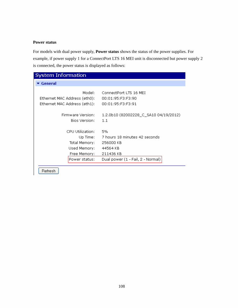
108
Power status
For models with dual power supply, Power status shows the status of the power supplies. For
example, if power supply 1 for a ConnectPort LTS 16 MEI unit is disconnected but power supply 2
is connected, the power status is displayed as follows:
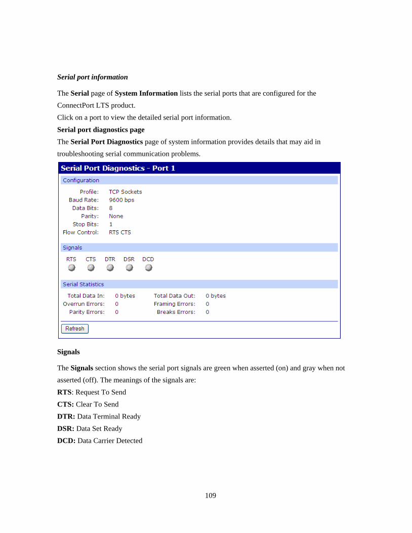
109
Serial port information
The Serial page of System Information lists the serial ports that are configured for the
ConnectPort LTS product.
Click on a port to view the detailed serial port information.
Serial port diagnostics page
The Serial Port Diagnostics page of system information provides details that may aid in
troubleshooting serial communication problems.
Signals
The Signals section shows the serial port signals are green when asserted (on) and gray when not
asserted (off). The meanings of the signals are:
RTS: Request To Send
CTS: Clear To Send
DTR: Data Terminal Ready
DSR: Data Set Ready
DCD: Data Carrier Detected

110
Serial statistics
The Serial statistics section of serial port information includes data counters and error tracking that
will help determine the quality of data that is being sent or received. If the error counters are
accumulating, there may be a problem in the ConnectPort LTS product.
Total Data In
Total number of data bytes received.
Total Data Out
Total number of data bytes transmitted.
Overrun Errors
Number of overrun errors - the next data character arrived before the hardware
could move the previous character.
Framing Errors
Number of framing errors received - the received data did not have a valid stop
bit.
Parity Errors
Number of parity errors - the received data did not have the correct parity setting.
Breaks
Number of break signals received.

111
Network statistics
Network statistics are detailed statistics about network and protocol activity that may aid in
troubleshooting network communication problems. Statistics displayed are those gathered since the
unit was last rebooted. If an error counter accumulates at an unexpected rate for that type of counter,
there may be a problem in the ConnectPort LTS product.
Ethernet Connection Statistics
Speed
Ethernet link speed: 10, 100 or 1000 Mbps. N/A if link integrity is not detected, for
example, if the cable is disconnected.
Duplex
Ethernet link mode: half or full duplex.
N/A if link integrity is not detected, for example, if the cable is disconnected
Bytes Received
Bytes Sent
Number of bytes received or sent.
Packets Received
Number of packets received and delivered to a higher-layer protocol.
Packets Sent
Number of packets requested to be sent by a higher-layer protocol.
IP Statistics
Datagrams Received
Datagrams Forwarded
Number of datagrams received or forwarded.
Forwarding
Displays whether forwarding is enabled or disabled.
No Routes
Number of outgoing datagrams for which no route to the destination IP could be found.
Routing Discards
Number of outgoing datagrams which have been discarded.
Default Time-To-Live
Number of routers an IP packet can pass through before being discarded.

112
TCP statistics
Segments Received
Segments Sent
Number of segments received or sent.
Active Opens
Number of active opens. In an active open, the ConnectPort LTS product is initiating a
connection request with a server.
Passive Opens
Number of passive opens. In a passive open, the ConnectPort LTS product is listening for
a connection request from a client.
Bad Segments Received
Number of segments received with errors.
Attempt Fails
Number of failed connection attempts.
Segments Retransmitted
Number of segments retransmitted. Segments are retransmitted when the server does not
respond to a packet sent by the client. This is to handle packets that might get lost or
discarded somewhere in the network.
Established Resets
Number of established connections that have been reset.
Currently Established
Number of established connections that have been reset.
Resets Sent
Number of established connections that have been reset.
113
UDP statistics
Datagrams Received
Datagrams Sent
Number of datagrams received or sent.
Bad Datagrams Received
Number of bad datagrams that were received. This number does not include the value
contained by No Ports.
No Ports
Number of received datagrams that were discarded because the specified port was invalid.
ICMP statistics
Messages Received
Number of messages received.
Bad Messages Received
Number of received messages with errors.
Destination Unreachable Messages Received
Number of destination unreachable messages received. A destination unreachable message
is sent to the originator when a datagram fails to reach its intended destination.
Messages Sent
Number of ICMP messages sent.
Dest. Unreachable Messages Sent
Number of ICMP destination unreachable messages sent.
IPv6 Messages Received
Number of messages received.
IPv6 Bad Messages Received
Number of received messages with errors.
IPv6 Destination Unreachable Messages Received
Number of destination unreachable messages received. A destination unreachable message
is sent to the originator when a datagram fails to reach its intended destination.
IPv6 Messages Sent
Number of IPv6 messages sent.
IPv6 Dest. Unreachable Messages Sent
Number of IPv6 destination unreachable messages sent.

114
XBee Network
This section is used to view more detailed statistics for XBee module activity that may aid in
troubleshooting network communication problems with your XBee network.
Gateway Device Details
This section shows the current PAN ID, Channel, and address in use for the XBee network.
Network View of the XBee Devices
Use the Discover XBee Devices button to refresh the list of devices which have joined the
XBee network. (Note that the discovery operation may take a few seconds.) Click on a
device's table entry to view more detailed information of the state of that device.
Node ID
The user assigned identifier of the node.
Network Address
The 16-bit network address of the node.
Extended Address
The unique 64-bit MAC address of the node.
Node Type
The role that the XBee module in the gateway serves in the XBee network.
For a gateway, the XBee module is a coordinator.
Product Type
The product type of the XBee module.
Clear list before device discovery
Clears the network view of XBee devices of any previously discovered nodes
prior to any new discovery/display XBee network actions.

115
Python Application XBee Socket Counters
This section includes data counters that are specific to ZigBee Sockets implemented using
a Python application.
Frames Sent
The total number of transmitted frames.
Frames Received
The total number of received frames.
Bytes Sent
The total number of bytes sent.
Bytes Received
The total number of bytes received.
Python Application XBee Socket Error Counts
This section includes error counters that are specific to ZigBee Sockets implemented using
a Python application. These values will help determine the quality of data that is being sent
or received.
Transmit Frame Errors
The total number of transmitted frames that could not be transmitted due to an I/O
error.
Receive Frame Errors
The total number of received frames where an error occurred.
Received Bytes Dropped
The total number of bytes dropped due to an exhaustion of internal buffers.
Received Bytes Truncated
Number of received bytes that were dropped because the user buffer passed to
recvfrom() was not large enough to contain the entire packet.

116
Manage connections and services
The Management menu is for viewing and managing connections and services for the ConnectPort
LTS product.
Manage serial ports
Management > Serial Ports provides an overview of the serial ports and their connections.
Clicking Connections displays the active connections for that serial port. The view can be refreshed
to see any new serial-port connections list, and connections can be disconnected as needed.
Manage connections
Management > Connections displays active system connections.
Manage PPP connections
The Active PPP Connections list provides an overview of connections associated with PPP
interfaces.
Manage active system connections
The Active System Connections list provides an overview of connections associated with various
interfaces, such as user connections to the device web interface, connections to the command line
through the local shell, or Python threads currently running; the protocols used for the connections;
and the number of active sessions for each connection. One of the uses of this list is to determine
whether any connections are no longer needed and can be disconnected.
117
Monitoring capabilities from the command line
There are several commands for monitoring ConnectPort LTS products and managing their
connections. For complete descriptions of these commands, see the ConnectPort LTS Command
Reference.
Commands for displaying device information and statistics
display
The display command displays real-time information about a device, such as:
General product information, including the product name, MAC address, boot, post, and
firmware versions, memory usage, utilization, and uptime, or the amount of time since the
device was booted (display device).
Active interfaces on the system, for example, the web interface, command line interface, Point
to Point Protocol (PPP), and Ethernet interface, and their status, such as Closed or Connected.
(display netdevice)
The event log (display buffers)
Memory usage information (display memory)
Serial modem signals (display serial)
General status of the sockets resource (display sockets)
Active TCP sessions and active TCP listeners (display tcp)
Current UDP listeners (display udp)
Point-to-Point Protocol (PPP) information (display pppstats)
Uptime information (display uptime).

118
info
The info command displays statistical information about a device over time. The statistics displayed
are those gathered since the tables containing the statistics were last cleared. Info keywords display
the following types of statistics:
Device statistics. info device displays such details as product, MAC address, bios, and firmware
versions, memory usage, utilization, and uptime. For models with dual power supplies, such as
ConnectPort LTS 16 MEI 2AC, this command displays the status of the power supplies.
Ethernet statistics. info ethernet displays statistics regarding the Ethernet interface, including
the number of bytes and packets sent and received, the number of incoming and outgoing bytes
that were discarded or that contained errors, the number of Rx overruns, the number of times
the transmitter has been reset, and the number of incoming bytes when the protocol was
unknown.
ICMP statistics. info icmp displays the number of messages, bad messages, and destination
unreachable messages received.
Serial statistics. info serial displays the number of bytes received and transmitted, signal
changes, FIFO and buffer overruns, framing and parity errors, and breaks detected.
TCP statistics. info tcp displays the number of segments received or sent, the number of active
and passive opens, the number of bad segments received, the number of failed connection
attempts, the number of segments retransmitted, and the number of established connections that
have been reset.
UDP statistics. info udp displays the number of datagrams received or sent, bad datagrams
received, and the number of received datagrams that were discarded because the specified port
was invalid.
ZigBee statistics. info zigbee_sockets displays the number of frames received or sent, bad
frames received or sent, the number of bytes received or sent and the number of received bytes
dropped or truncated.

119
set alarm
set alarm displays alarm settings, including conditions that trigger alarms, and how alarms are sent,
either as an email message, an SNMP trap, or both. Alarms can be reconfigured as needed.
set buffer and display buffers
set buffer configures buffering parameters on a port and displays the current port buffer
configuration. display buffers displays the contents of a port buffer, or transfers the port-buffer
contents to a server running Trivial File Transfer Protocol (TFTP).
set snmp
set snmp configures SNMP, including SNMP traps, such as authentication failure, cold start, link
up, and login traps, and displays current SNMP settings.
show
Displays current settings in a device.

120
Commands for managing connections and sessions
close: Closes active sessions that were opened by connect, rlogin, and telnet commands.
connect: Makes a connection, or establishes a connection, with a serial port.
exit and quit: These commands terminate a currently active session.
who and kill: The who command displays a global list of connections. The list of connections
includes those associated with a serial port or the command-line interface. who is particularly
useful in conjunction with the kill command, which terminates active connections. Use who to
determine any connections that are no longer needed, and end the connections by issuing a kill
command.
ping: Tests whether a host or other device is active and reachable.
reconnect: Reestablishes a previously established connection. The default operation is to
reconnect to the last active session.
rlogin: Performs a login to a remote system.
status: Displays a list of sessions, or outgoing connections made by connect, rlogin, telnet or
ssh commands for a device. Typically, the status command is used to determine which of the
current sessions to close.
telnet: Makes an outgoing Telnet connection, also known as a session.

121
Monitoring Capabilities from SNMP
Device monitoring capabilities from SNMP include, among other things:
Network statistics, defined in RFC 1213, MIB-II
Port statistics, defined in RFCs 1316 and 1317
Device information, defined in Digi enterprise MIB DIGI-DEVICE-INFO.mib
For more information on the statistics available through the standard RFCs listed above, refer to the
RFCs available on the IETF web site (www.ietf.org). For enterprise MIBs, refer to the description
fields in the MIB text.
122
5 Administration tasks
This chapter discusses the administration tasks that need to be performed on ConnectPort LTS
products periodically, such as file management, changing the password used for logging onto the
device, backing up and restoring device configurations, updating firmware and Boot/POST code,
restoring the device configuration to factory defaults, and rebooting the device. As with device
configuration and monitoring, it covers performing administrative tasks through a variety of device
interfaces.
It covers these main topics:
Administration from the web interface
Administration from the command-line interface
Administration from the web interface
The Administration section of the web interface main menu provides the following choices:
File Management: For uploading and managing files, such as custom web pages and
initialization files.
Backup/Restore: For backing up or restoring device configuration settings.
Python Program File Management: For uploading custom programs in the Python
programming language to ConnectPort LTS products and configuring the programs to execute
automatically at startup.
Update Firmware: For updating firmware, including Boot and POST code.
Factory Default Settings: For restoring a device to factory default settings.
System Information: For displaying general system information for the device and device
statistics.
Reboot: For rebooting the device.
These administrative tasks are organized elsewhere in the web interface:
Enable and disable network services. See "Network services settings."
Enable password authentication for the ConnectPort LTS product. See "User settings."

123
File management
The File Management page of the web interface uploads custom files to a ConnectPort LTS
product. Custom files allow the flexibility to alter the interface either by adding a different company
logo, changing colors, or moving information to different locations. If custom files are note, using
this feature is not necessary.
Upload files
To upload files to a ConnectPort LTS product, enter the file path and name for the file, or click
Browse to locate and select the file, and click Upload.
Delete files
To delete files from a ConnectPort LTS product, select the file from the list under Manage Files
and click Delete.
Custom files are not deleted by device reset
Any files uploaded to the file system of a ConnectPort LTS product from the File Management page
are not deleted by restoring the device configuration to factory defaults, or by pressing the Reset
button on the device (see "Restore a device configuration to factory defaults"). This deletion is
prevented so that customers with custom applets and custom factory defaults can retain them on the
device and not have them deleted by a reset. Such files can only be deleted by the Delete operation,
described above. Root user also can delete custom files directly on the CLI shell by accessing
command line interface.

124
Backup/restore device configurations
Once a ConnectPort LTS product is configured, backing up the configuration settings is
recommended in case problems occur later, firmware is upgraded, or hardware is added. If multiple
devices need to be configured, the backup/restore feature can be used as a convenience, where the
device configuration settings are backed up to a file, then the file is loaded onto the other devices.
Backup/restore device configuration from the web interface
This procedure shows how to back up or restore the configuration to a server and download a
configuration from a server to a file. The default filename for the backup file is backup.cfg.
1. From the Main menu, click Administration > Backup/Restore. The Backup/Restore page is
displayed.
2. Choose the appropriate option (Backup or Restore) and select the file.
Location: Location of backup (or restore) configuration file. The ConnectPort LTS basic
version supports NFS/Samba/User space/Local machine for location.
Keep Network Settings: Selecting this option this will retain basic network settings, such as IP
address, Subnet Mask, and Gateway.

125
Backup/restore device configuration from a TFTP or BOOTP Server from the command line
From the command-line interface, the ―backup‖ command backs up the device configuration to a
TFTP or BOOTP server located on the network or a storage device in the ConnectPort LTS device,
or restores the configuration.
backup [to=serveripaddress[:filename]|
[to={sd|usb|nfs|samba|userspace}[:filename]]
[from=serveripaddress[:filename] print]|
[from={sd|usb|nfs|samba|userspace}[:filename]]
Where:
to=serveripaddress[:filename]
The IP address of the TFTP server to which the configuration will be saved, and
the filename that the configuration will be saved as. If a filename is not specified,
the default filename of config.rci is used.
to=(sd|usb|nfs|samba|userspace)[:filename]
The location of the storage device to which the configuration will be saved, and
the filename that the configuration will be saved as. If a filename is not specified,
the default filename of config.rci is used.
from=serveripaddress[:filename]
The IP address of the TFTP server and the filename from which the configuration
will be restored. If a filename is not specified, the default filename of config.rci is
assumed. In ConnectPort LTS, the system will be rebooted after restoring
configuration.
from=(sd|usb|nfs|samba|userspace)[:filename]
The location of the storage device and the filename from which the configuration
will be restored. If a filename is not specified, the default filename of config.rci is
used.
Prints out the current device configuration.
Example #> backup from=10.0.0.1:config.rci
126
Update firmware
The firmware for a ConnectPort LTS product can be updated in several ways:
In the web interface, by the Administration > Update Firmware page
From the command-line interface, via TFTP or BOOTP.
The recommended method for firmware upgrade is to download the firmware to a local hard drive.
Prerequisites
These procedures assume that:
A firmware file has already been downloaded from the Digi web site.
That TFTP or BOOTP is running.
Update firmware from a file from the web interface
1. From the Main menu, click Administration > Update Firmware. The Update Firmware page
is displayed.
2. Enter the name of the firmware file in the Select Firmware edit box, or click Browse to locate
and select the firmware.
3. Click Update.
Important: DO NOT close the browser until the update is complete and a reboot prompt has
been displayed.
Update firmware from a TFTP or BOOTP Server from the command line
Updating firmware and from a TFTP or BOOTP server is done from the command-line interface
using this command:
boot load=host ip address:loadfile
See the description of the ―boot‖ command in the ConnectPort LTS Command Reference for more
information.
Update BIOS code
BIOS code can be updated through the boot loader only. To update BIOS code, see ―Disaster
recovery‖ on page 142.
Before uploading the firmware, it is very important to read the Release Notes supplied with the
firmware to check if the BIOS code must be updated before updating the firmware.

127
Restore a device configuration to factory default settings
Restoring a ConnectPort LTS product to its factory default settings clears all current configuration
settings. Selecting the Keep network settings option retains the IP address settings. In addition, any
files that were loaded into the device through the File Management page such as custom-interface
files and applet files are retained. See "File management" for information on loading and deleting
files.
There are several ways to reset the device configuration of a ConnectPort LTS product to the
factory default settings:
From the web interface using the Restore Factory Defaults operation
From the command-line interface, using the boot or revert commands
Using the reset button on the ConnectPort LTS product.
From the LCD display under Miscellaneous.
Settings cleared and retained during factory reset
The Factory Default Settings operation clears all current settings. Selecting the Keep network
settings option retains the IP address settings. This is the best way to reset the configuration,
because the settings can also be backed up using the Backup/Restore operation, which provides a
means for restoring it after the configuration issues have been resolved. The Restore Only Serial
Port Settings option restores only the serial settings to their factory defaults, and leaves the
remainder of the configuration settings as-is.
Using the web interface
1. Make a backup copy of the configuration using the Backup/Restore operation, see
―Backup/restore Device Configurations.‖
2. From the Main menu, click Administration > Factory Default Settings. The Factory Default
Settings page is displayed.
3. If it is desired to keep the network settings for the device, such as the IP address, select
Keep network settings option. If it is desired to reset the serial port settings only, select the
Restore Only Serial Port Settings option.
4. Restore.

128
Using the Reset button
If the ConnectPort LTS device cannot be accessed from the web interface, the configuration can be
restored to factory defaults by using the Reset button. In this case, all current settings including the
IP settings will be cleared.
Reset ConnectPort LTS
1. Locate the Factory Reset button on the front of device, as shown in the figure. Use a non-
conducive, small diameter tool (such as wood or plastic) with a blunt end (NOT SHARP or the
button could be damaged) to press gently.
2. Hold down the reset button about 2~3 seconds and then release it.
3. Check the status of Ready LED. When the restoration is complete, Ready LED will be turn on
again.

129
Display system information
System information displays the model, MAC address, firmware version, and bios version of the
ConnectPort LTS product. It also displays memory available: total, used, and free, and tracks CPU
percent utilization and the uptime.
From the web interface menu, select Administration > System Information. Select
General, Serial, or Network for the appropriate information. For descriptions of the information
displayed on these screens, see ―Display System Information.‖
Reboot the ConnectPort LTS product
Changes to some device settings require saving the changes and rebooting the ConnectPort LTS
product. To reboot a ConnectPort LTS product:
1. From the web interface menu, select Administration > Reboot.
2. On the Reboot page, click the Reboot button. Wait approximately 1 minute for the reboot
to complete.
Enable/disable access to network services
As needed, enable and disable access to various network services, such as ADDP, RealPort, SNMP,
Telnet and ssh. For example, for performance and security reasons, it may be desirable to disable
access to all network services not necessary for running or interfacing with the ConnectPort LTS
product. In the web interface, enabling and disabling network services is done on the Network
Services settings page for a ConnectPort LTS product. See "Network services settings".
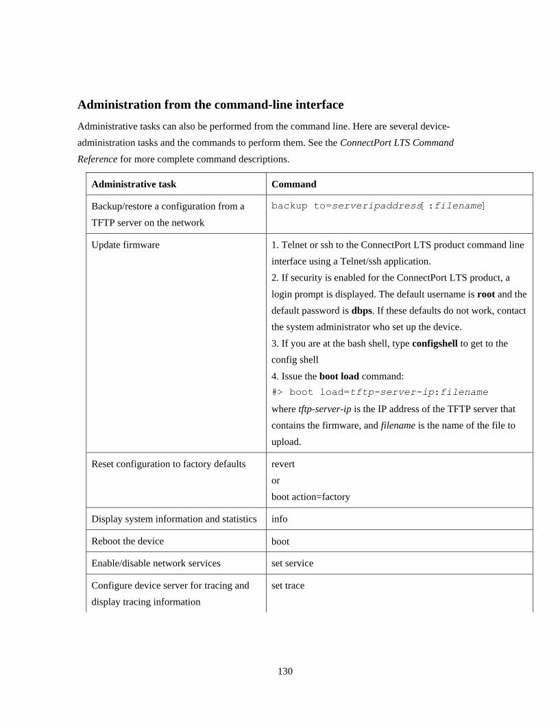
130
Administration from the command-line interface
Administrative tasks can also be performed from the command line. Here are several device-
administration tasks and the commands to perform them. See the ConnectPort LTS Command
Reference for more complete command descriptions.
Administrative task Command
Backup/restore a configuration from a
TFTP server on the network
backup to=serveripaddress[:filename]
Update firmware 1. Telnet or ssh to the ConnectPort LTS product command line
interface using a Telnet/ssh application.
2. If security is enabled for the ConnectPort LTS product, a
login prompt is displayed. The default username is root and the
default password is dbps. If these defaults do not work, contact
the system administrator who set up the device.
3. If you are at the bash shell, type configshell to get to the
config shell
4. Issue the boot load command:
#> boot load=tftp-server-ip:filename
where tftp-server-ip is the IP address of the TFTP server that
contains the firmware, and filename is the name of the file to
upload.
Reset configuration to factory defaults revert
or
boot action=factory
Display system information and statistics info
Reboot the device boot
Enable/disable network services set service
Configure device server for tracing and
display tracing information
set trace

131
6 LCD interface: configuration, monitoring, and
diagnostics
This chapter discusses how to configure, monitor or diagnose the ConnectPort LTS using the
LCD interface. It covers these topics:
Description for basic key pad operation and LCD display
Configuration using the LCD interface
Monitoring using the LCD interface
Diagnostics using the LCD interface
Miscellaneous functions in the LCD interface.
Basic keypad operation and LCD display
Keys
There are four keys on the right side of LCD display to control the LCD interface. The functions of
each key are as follows,
Up: Moves cursor upward. (The currently selected menu item will be displayed with white
characters on black background.)
Dn: Moves cursor downward.
Sel: Selects the current menu item. If the item has submenu, a black triangle mark is displayed
at the end of line. If the item does not have submenu, the action assigned to the menu item will
be performed.
Ext: Goes to the upper menu or causes an action assigned to the menu item selected. The
current menu level is displayed on the left top side of the LCD screen. The upper menu is
displayed on the top left side of the LCD screen.

132
Keypad operations
When you turn on the ConnectPort LTS, the following default image is displayed on the LCD
screen:
Pressing any key displays the main menu screen on the LCD screen.
The black triangle on the right end of each menu item indicates the menu item has submenus. If you
press Sel key again, the following configuration submenu screen is displayed on the LCD screen.
On this screen, the CONFIG message on the top left side indicates you are on the configuration
menu. The MAIN message on the top right side indicates the upper menu is the main menu. (To go
o the upper menu, press Ext on this screen.)
Pressing the Dn key causes IP SETTINGS #2 to be selected as follows:

133
Configuration using the LCD interface
You can set the following configurations using the LCD interface:
IP settings #1: Sets IP mode, IP address, Subnet mask, and the default gateway of network
interface #1. (You can only set IPv4 mode. LCD interface does not support the configuration of
IPv6 mode.)
IP settings #2: Sets IP mode, IP address, Subnet mask, the default Gateway of network
interface #2.
Host name: Host name of the device.
DNS: Primary DNS of the device.
Change IP settings
Set IP Mode
Enter the IP settings menu by selecting CONFIGURATION and then IP SETTINGS #1 or
IP SETTINGS #2. The following menu is displayed:
By selecting the IP MODE menu item, you can choose one of following IP mode options,
DISABLE: Disable this Ethernet interface.
STATIC IP: Set the mode of IP address to STATIC.
DHCP: Set the mode of IP address to DHCP.

134
Set IP Address
If you select IP Mode to STATIC, you can change or set the IP address, subnet mask and gateway
settings. When you select IP ADDRESS menu item, the following menu is displayed:
On this screen, you can move cursor position using Up (Left) and Dn (Right) keys. Once you locate
the cursor on the position you want to change, you can press Sel key to enter the editing submenu as
follows:
On this editing submenu screen you can select EDIT menu to change the letter you choose or
CLEAR ALL menu to clear all IP address letters displayed on the screen. If you select EDIT menu,
then you can enter the selection submenu as follows:
On this selection submenu screen, you can choose a letter using Up (Left) and Dn (Right) keys. The
IP address on the upper line will be changed also automatically as follows:
Note that you can choose null character (first letter) to clear the letter selected.

135
After changing the selected letter, you can choose another letter by pressing Ext key twice. Repeat
the steps to change the letter as described above. When done changing the letters as desired, press
the Ext key on the following screen:
You can then enter the IP settings menu again. Continue to change SUBNET MASK or
GATEWAY in the manner described above.
After completing the settings changes, press the Ext key on the IP SETTINGS menu. Then choose
one of following options:
SAVE APPLY: Save configuration changed and apply them to the ConnectPort LTS product.
DISCARD CHANGES: Discard all changes.
CANCEL: Go back to IP SETTINGS menu.

136
Change the hostname
Enter the host name menu by selecting CONFIGURATION and then HOST NAME. The
following menu is displayed:
Press the Sel key again. This menu is displayed:
Move cursor position using Up (Left) and Dn (Right) keys. Once you locate the cursor on the
position you want to change, press the Sel key to enter the editing submenu as follows:
On this editing submenu screen, select EDIT to change the desired letter or CLEAR ALL to clear
all host names displayed on the screen. Selecting EDIT displays the following selection submenu:
On this selection submenu, choose a letter using Up (Left) and Dn (Right) keys. The host name on
the upper line will be changed automatically as follows:

137
After changing the selected letter, choose another letter by pressing Ext key twice. Repeat the steps
to change the letter just described above. When done changing letters, press the Ext key several
times until you meet following screen.
Then choose one of following options,
SAVE APPLY: Save configuration changed and apply it.
DISCARD CHANGES: Discard all changes.
CANCEL: Go back to the HOST NAME menu.

138
Change the DNS configuration
Select CONFIGURATION and then DNS. The following menu is displayed:
Press the Sel key again. The following menu is displayed:
If you choose the ENABLE option and press the Ext key, the following menu is displayed:
Set the IP address of the DNS server in the same manner as setting the IP address.

139
Monitoring using the LCD interface
The following information can be monitored through the LCD interface.
Serial port
- Configuration: Profile, Baudrate, Data Bit, Parity Bit, Stop Bit, Flow control, Port Type
- Signal status: RTS, CTS, DTR, DSR, DCD
- Statistics: Data In, Data out, Parity Error, Framing Error, Overrun error
Ethernet
- Speed, Duplex, Bytes Received, Bytes Sent, Packets Received, Packet Sent
System
- Product Model, F/W version, Bios version, IP Address, MAC address, CPU Utilization, UP
Time, Memory(Total, Used, Free)
Diagnostics using the LCD interface
The following diagnostics can be run through the LCD interface:
Auto Test: Run all possible hardware tests and show the results.
Individual Test: Run the following tests by selection or manually: EEPROM, UART (Internal
& External), Ethernet, USB, SD Memory, Modem, XBee.

140
Miscellaneous functions in LCD interface
The Miscellaneous menu has the following functions.
Factory Reset: Restore the configuration to factory defaults.
LCD setting
- Reset the LCD configuration
- Select a background image
Factory Reset
Enter the factory reset menu by selecting MISCELLANEOUS and then FACTORY RESET. The
following menu screen is displayed.
If you select APPLY, all configuration of the device restored to factory default value and the device
is rebooted automatically.

141
LED Settings
When you enter the LCD setting menu by selecting MISCELLANEOUS and then
LCD SETTINGS, the following menu is displayed:
Reset
RESET allows resetting the LCD configuration, including whether a custom or default background
image is used. Selecting RESET displays a confirmation:
Select Image
SELECT IMAGE is for choosing the background image option as follows:

142
7 Disaster recovery
The Digi ConnectPort LTS unit provides a disaster recovery procedure in the event the
configuration data is destroyed or corrupted. The Digi ConnectPort LTS unit automatically restores
a corrupted configuration file system to the factory default settings. However, if the Digi
ConnectPort LTS unit fails to boot in spite of being reset to the factory default settings, the
firmware can be restored using the Bios menu.
Restore Digi ConnectPort LTS to Factory Default Settings
To restore the Digi ConnectPort LTS unit to the factory default configuration settings, use a TFTP
or BOOTP server. To use the Bios menu to flash new firmware and/or new BIOS code revision, do
the following:
1. Connect the console port on the rear panel of the Digi ConnectPort LTS unit to a serial port on a
workstation. Use the supplied RJ45/DB9F console adapter and an Ethernet cable.
2. Set up a terminal emulation program such as HyperTerminal. Use the following port parameters:
- bps=9600
- data bits=8
- parity=none
- stop bits=1
- flow control=none
3. Reboot or power on the Digi ConnectPort LTS unit.
4. Press the ESC key within three seconds of applying power to the device. The following screen
is displayed. Use the ESC key to return to an earlier menu screen, and the Enter key to refresh
the menu screen.
5. Choose Firmware upgrade by entering 3. The following screen is displayed.

143
6. Enter the information for the first menu items.
- Protocol: The choices are BOOTP or TFTP.
- IP address assigned: Enter the IP address of the Digi ConnectPort LTS unit.
- Server’s IP address: The IP address of the BOOTP or TFTP server.
- Firmware File Name: The filename for the firmware.
- Ethernet interface: 1 or 2.
7. Use the ESC key to return to earlier menu screens.
8. Select Start firmware upgrade. The firmware upgrade can take 15 to 20 minutes to process.
Please leave the ConnectPort LTS unit alone until the firmware update is complete.
9. When the upgrade process is complete, the device will reboot and the factory default settings
will be restored.

144
8 Hardware specifications
Hardware specifications for this product are located at:
http://www.digi.com/products/serialservers/connectportlts#specs

145
9 Regulatory Information and Certifications
FCC certifications and regulatory information (USA only)
FCC Part 15 Class B
These devices comply with the standards cited in this section:
ConnectPort LTS 16
ConnectPort LTS 32
Radio Frequency Interface (RFI) (FCC 15.105)
This device has been tested and found to comply with the limits for Class B digital devices pursuant
to Part 15 Subpart B, of the FCC rules. These limits are designed to provide reasonable protection
against harmful interference in a residential environment. This equipment generates, uses, and can
radiate radio frequency energy, and if not installed and used in accordance with the instruction
manual, may cause harmful interference to radio communications. However, there is no guarantee
that interference will not occur in a particular installation. If this equipment does cause harmful
interference to radio or television reception, which can be determined by turning the equipment off
and on, the user is encouraged to try and correct the interference by one or more of the following
measures:
Reorient or relocate the receiving antenna.
Increase the separation between the equipment and receiver.
Connect the equipment into an outlet on a circuit different from that to which the receiver is
connected.
Consult the dealer or an experienced radio/TV technician for help.
Labeling Requirements (FCC 15.19)
This device complies with Part 15 of FCC rules. Operation is subject to the following two
conditions: (1) this device may not cause harmful interference, and (2) this device must accept any
interference received, including interference that may cause undesired operation. If the FCC ID is
not visible when installed inside another device, then the outside of the device into which the
module is installed must also display a label referring to the enclosed module FCC ID.

146
Modifications (FCC 15.21)
Changes or modifications to this equipment not expressly approved by Digi may void the user’s
authority to operate this equipment.
Declaration of Conformity
(In accordance with FCC Dockets 96-208 and 95-19)
Manufacturer’s Name: Digi International
Corporate Headquarters: 11001 Bren Road East
Minnetonka MN 55343
Manufacturing Headquarters: 10000 West 76th Street
Eden Prairie MN 55344
Digi International declares, that the product:
Product Name Model Number
ConnectPort LTS 50001688-xx
to which this declaration relates, meets the requirements specified by the Federal Communications
Commission as detailed in the following specifications:
Part 15, Subpart B, for Class B equipment
FCC Docket 96-208 as it applies to Class B personal computers and peripherals
The product listed above has been tested at an External Test Laboratory certified per FCC rules and
has been found to meet the FCC, Part 15, Class B, Emission Limits. Documentation is on file and
available from the Digi International Homologation Department.
Industry Canada (IC) certifications
This digital apparatus does not exceed the Class B limits for radio noise emissions from digital
apparatus set out in the Radio Interference Regulations of the Canadian Department of
Communications.
Le present appareil numerique n’emet pas de bruits radioelectriques depassant les limites
applicables aux appareils numeriques de la class B prescrites dans le Reglement sur le brouillage
radioelectrique edicte par le ministere des Communications du Canada.

147
Safety statements
5.10 Ignition of Flammable Atmospheres
Warnings for Use of Wireless Devices
Observe all warning notices regarding use of wireless devices.
Potentially Hazardous Atmospheres
Observe restrictions on the use of radio devices in fuel depots, chemical plants, etc. and areas where
the air contains chemicals or particles, such as grain, dust, or metal powders, and any other area
where you would normally be advised to turn off your vehicle engine.
Safety in Aircraft
Switch off the wireless device when instructed to do so by airport or airline staff. If the device
offers a ‖flight mode‖ or similar feature, consult airline staff about its use in flight.
Safety in Hospitals
Wireless devices transmit radio frequency energy and may affect medical electrical equipment.
Switch off wireless devices wherever requested to do so in hospitals, clinics, or healthcare facilities.
These requests are designed to prevent possible interference with sensitive medical equipment.
Pacemakers
Pacemaker manufacturers recommended that a minimum of 15cm (6 inches) be maintained between
a handheld wireless device and a pacemaker to avoid potential interference with the pacemaker.
These recommendations are consistent with independent research and recommendations by
Wireless Technology Research.
Persons with Pacemakers:
ALWAYS keep the device more than 15cm (6 inches) from their pacemaker when turned ON.
Do not carry the device in a breast pocket.
If you have any reason to suspect that the interference is taking place, turn OFF your device.

148
Rack-mountable:
1. Elevated Operating Ambient Temperature: If installed in a closed or multi-unit rack
assembly, the operating ambient temperature of the rack environment may be greater than room
ambient. Therefore, consideration should be given to installing the equipment in a
environment compatible with the manufacturer’s maximum rated ambient temperature (Tmra).
2. Reduced Air Flow: Installation of the equipment in a rack should be such that the amount of
air flow required for safe operation of the equipment is not compromised,
3. Mechanical Loading: Mounting of the equipment in the rack should be such that a hazardous
condition is not achieved due to uneven mechanical loading.
4. Circuit Overloading: Consideration should be given to the connection of the equipment to the
supply circuit and the effect that overloading of circuits might have on over-current protection
and supply wiring. Appropriate consideration of equipment nameplate ratings should be used
when addressing this concern.
5. Reliable Earthing: Reliable earthing of rack-mounted equipment should be maintained.
Particular attention should be given to supply connections other than direct connections to the
branch circuit.

149
Lithium Battery
CAUTION
Danger of explosion if battery is incorrectly replaced.
Replace only with the same or equivalent type recommended by the manufacturer.
(Manufacturer: SONY FUKUSHIMA CORP., Model: CR2032.)
DISPOSE OF USED BATTERIES ACCORDING TO THE NATIONAL CODE OR
RECYCLING PROGRAM.
Modem
CAUTION
To reduce the risk of fire, use only No. 26AWG or larger telecommunication line cord.
Cabling
To determine the proper cable requirements for your application, please refer to the
Cable Guide for all PortServer® TS, Digi Connect®, and Digi One® Products (Digi part number
90000253).