Embed Size (px)
Citation preview
1
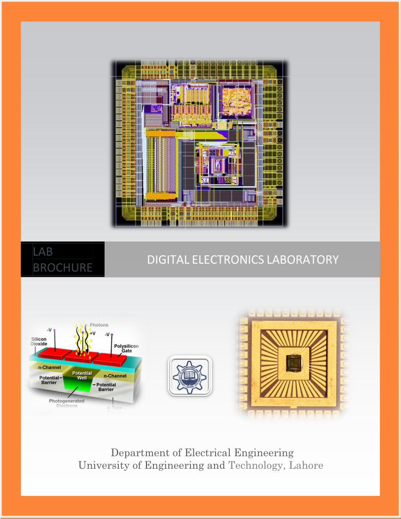
Department of Electrical Engineering
University of Engineering and Technology, Lahore
LAB BROCHURE
DIGITAL ELECTRONICS LABORATORY
2
LABORATORY VENUE
First Floor, Department of Electrical Engineering
University of Engineering and Technology, Lahore
LABORATORY OBJECTIVE
The experiments covered in this laboratory are
synchronized with its theoretical part, so that
students might be able to understand the practical
aspects of the course. The main objective of this
laboratory is to give:
Introduction to different steps used in the
design of digital systems according to
industrial standards
Complete knowledge of simulation software
(e.g. Spice and Electric VLSI System Design)
used in industry for VLSI design
Comprehensive detail of different solid state
pulse circuits and their applications
DIG
ITA
L E
LE
CT
RO
NIC
S L
AB
OR
AT
OR
De
pa
rtme
nt o
f Ele
ctrical E
ng
ine
erin
g U
niv
ersity
of E
ng
ine
erin
g a
nd
Te
chn
olo
gy
La
ho
re
3
LABORATORY INSTRUCTORS
Mr. Nauman Ahmad [Lecturer]
Mr. M. Fahad Ijaz [Lecturer / Lab
Engineer]
Mr. Ahmad Umair [Lecturer / Lab
Engineer]
Mr. Farrukh Yaqub [Lecturer / Lab
Engineer]
LABORATORY STAFF
DIG
ITA
L E
LE
CT
RO
NIC
S L
AB
OR
AT
OR
De
pa
rtme
nt o
f Ele
ctrical E
ng
ine
erin
g U
niv
ersity
of E
ng
ine
erin
g a
nd
Te
chn
olo
gy
La
ho
re
DIG
ITA
L E
LE
CT
RO
NIC
S L
AB
OR
AT
OR
De
pa
rtme
nt o
f Ele
ctrical E
ng
ine
erin
g U
niv
ersity
of E
ng
ine
erin
g a
nd
Te
chn
olo
gy
La
ho
re
4
Mr. Mairaj Din [Lab Attendant]
Mr. Fazal Elahi [Lab Assistant]
Mr. Muhammad Saleem [Lab Assistant]
LABORATORY FACILITIES
The lab is equipped with high performance dual
core processor desktops that can be used to run
latest simulation software for VLSI design,
oscilloscopes, function generators, regulated
power supplies and a whole range of different ICs
and discrete electronic devices.
DIG
ITA
L E
LE
CT
RO
NIC
S L
AB
OR
AT
OR
De
pa
rtme
nt o
f Ele
ctrical E
ng
ine
erin
g U
niv
ersity
of E
ng
ine
erin
g a
nd
Te
chn
olo
gy
La
ho
re
5
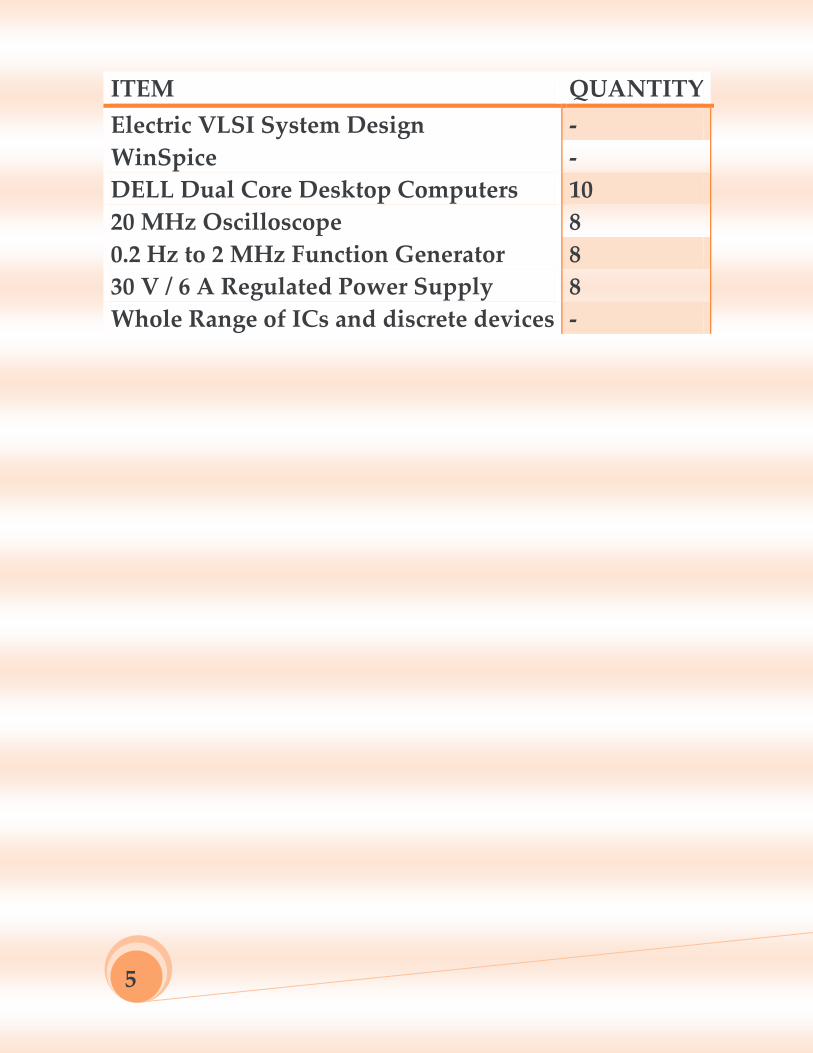
ITEM QUANTITY
Electric VLSI System Design -
WinSpice -
DELL Dual Core Desktop Computers 10
20 MHz Oscilloscope 8
0.2 Hz to 2 MHz Function Generator 8
30 V / 6 A Regulated Power Supply 8
Whole Range of ICs and discrete devices -
6
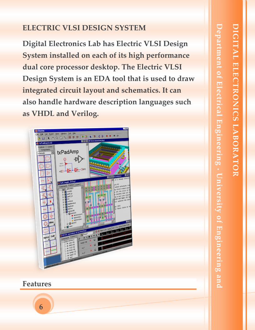
ELECTRIC VLSI DESIGN SYSTEM
Digital Electronics Lab has Electric VLSI Design
System installed on each of its high performance
dual core processor desktop. The Electric VLSI
Design System is an EDA tool that is used to draw
integrated circuit layout and schematics. It can
also handle hardware description languages such
as VHDL and Verilog.
Features
DIG
ITA
L E
LE
CT
RO
NIC
S L
AB
OR
AT
OR
De
pa
rtme
nt o
f Ele
ctrical E
ng
ine
erin
g U
niv
ersity
of E
ng
ine
erin
g a
nd
Te
chn
olo
gy
La
ho
re
DIG
ITA
L E
LE
CT
RO
NIC
S L
AB
OR
AT
OR
De
pa
rtme
nt o
f Ele
ctrical E
ng
ine
erin
g U
niv
ersity
of E
ng
ine
erin
g a
nd
Te
chn
olo
gy
La
ho
re
7
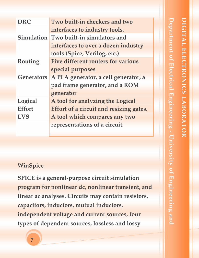
DRC Two built-in checkers and two
interfaces to industry tools.
Simulation Two built-in simulators and
interfaces to over a dozen industry
tools (Spice, Verilog, etc.)
Routing Five different routers for various
special purposes
Generators A PLA generator, a cell generator, a
pad frame generator, and a ROM
generator
Logical
Effort
A tool for analyzing the Logical
Effort of a circuit and resizing gates.
LVS A tool which compares any two
representations of a circuit.
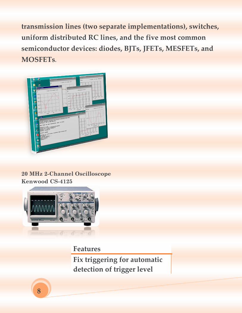
WinSpice
SPICE is a general-purpose circuit simulation
program for nonlinear dc, nonlinear transient, and
linear ac analyses. Circuits may contain resistors,
capacitors, inductors, mutual inductors,
independent voltage and current sources, four
types of dependent sources, lossless and lossy
DIG
ITA
L E
LE
CT
RO
NIC
S L
AB
OR
AT
OR
De
pa
rtme
nt o
f Ele
ctrical E
ng
ine
erin
g U
niv
ersity
of E
ng
ine
erin
g a
nd
Te
chn
olo
gy
La
ho
re
8
transmission lines (two separate implementations), switches,
uniform distributed RC lines, and the five most common
semiconductor devices: diodes, BJTs, JFETs, MESFETs, and
MOSFETs.
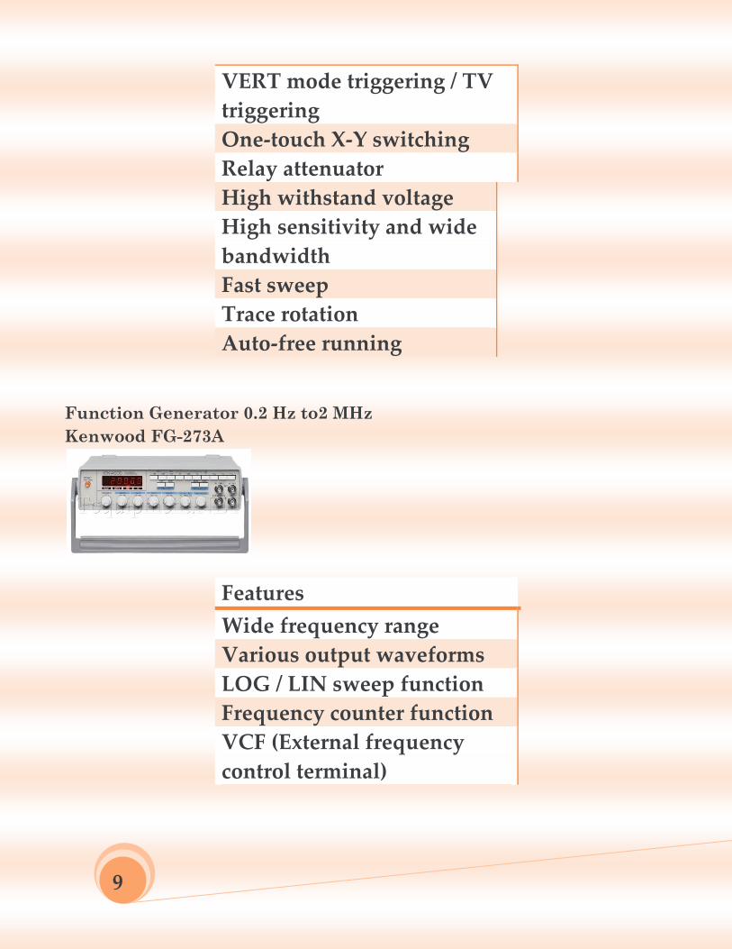
20 MHz 2-Channel Oscilloscope
Kenwood CS-4125
Features
Fix triggering for automatic
detection of trigger level
9
VERT mode triggering / TV
triggering
One-touch X-Y switching
Relay attenuator
High withstand voltage
High sensitivity and wide
bandwidth
Fast sweep
Trace rotation
Auto-free running
Function Generator 0.2 Hz to2 MHz
Kenwood FG-273A
Features
Wide frequency range
Various output waveforms
LOG / LIN sweep function
Frequency counter function
VCF (External frequency
control terminal)
1
0
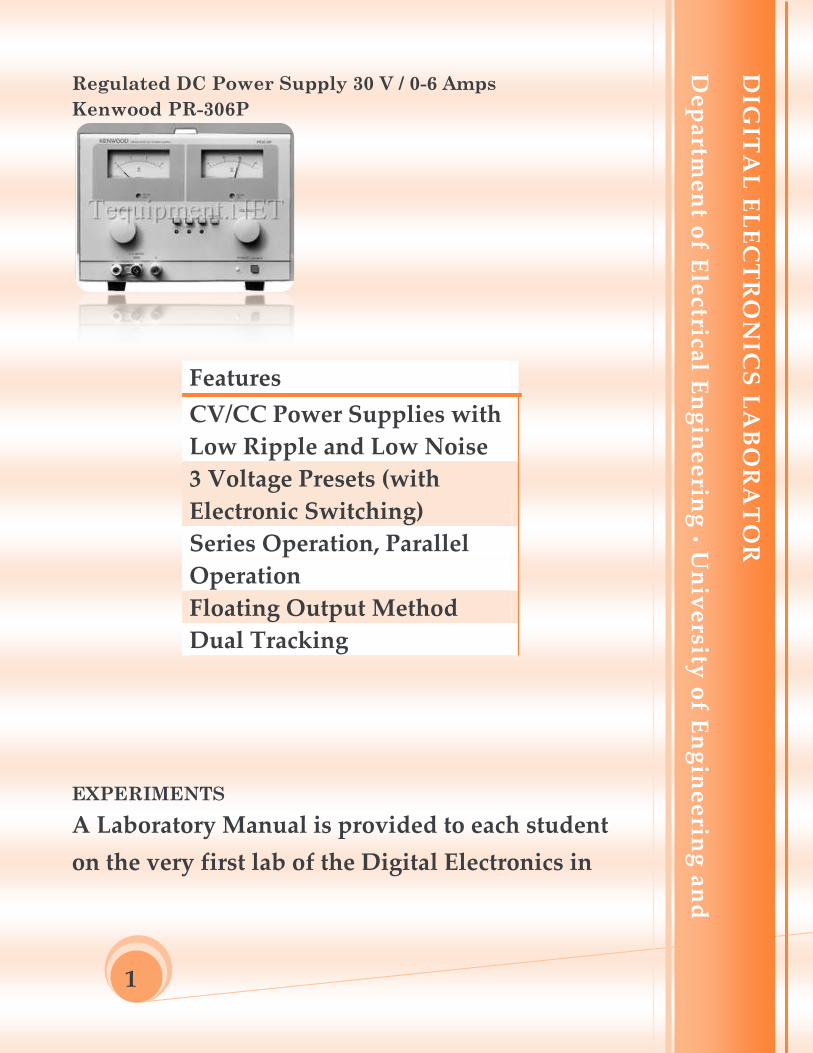
Regulated DC Power Supply 30 V / 0-6 Amps
Kenwood PR-306P
Features
CV/CC Power Supplies with
Low Ripple and Low Noise
3 Voltage Presets (with
Electronic Switching)
Series Operation, Parallel
Operation
Floating Output Method
Dual Tracking
EXPERIMENTS
A Laboratory Manual is provided to each student
on the very first lab of the Digital Electronics in
DIG
ITA
L E
LE
CT
RO
NIC
S L
AB
OR
AT
OR
De
pa
rtme
nt o
f Ele
ctrical E
ng
ine
erin
g U
niv
ersity
of E
ng
ine
erin
g a
nd
Te
chn
olo
gy
La
ho
re
1
1
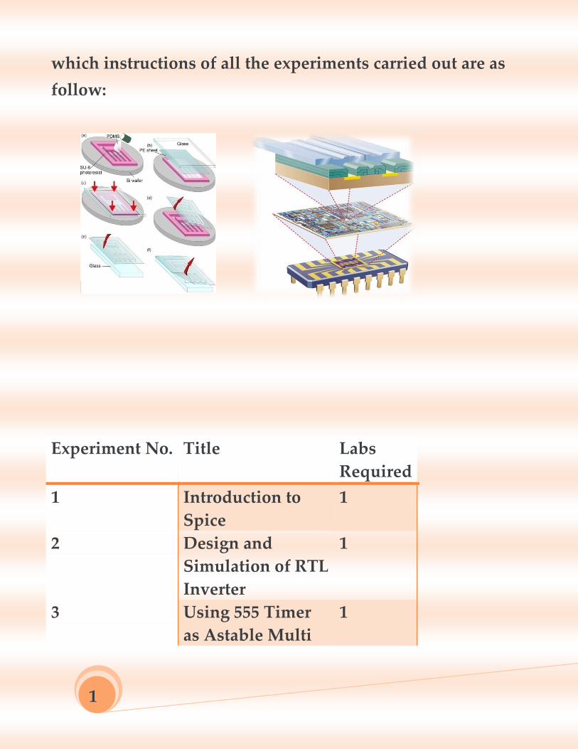
which instructions of all the experiments carried out are as
follow:
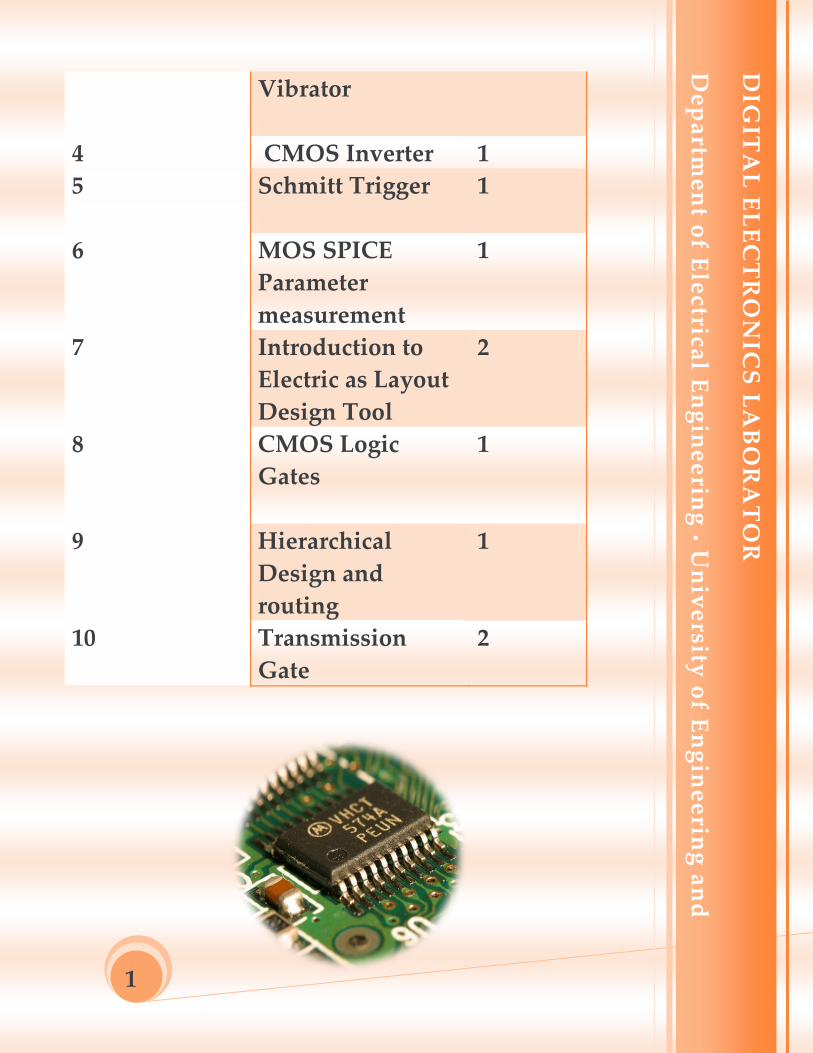
Experiment No. Title Labs
Required
1 Introduction to
Spice
1
2 Design and
Simulation of RTL
Inverter
1
3 Using 555 Timer
as Astable Multi
1
1
2
Vibrator
4 CMOS Inverter 1
5 Schmitt Trigger
1
6 MOS SPICE
Parameter
measurement
1
7 Introduction to
Electric as Layout
Design Tool
2
8 CMOS Logic
Gates
1
9 Hierarchical
Design and
routing
1
10 Transmission
Gate
2
DIG
ITA
L E
LE
CT
RO
NIC
S L
AB
OR
AT
OR
De
pa
rtme
nt o
f Ele
ctrical E
ng
ine
erin
g U
niv
ersity
of E
ng
ine
erin
g a
nd
Te
chn
olo
gy
La
ho
re
1
3
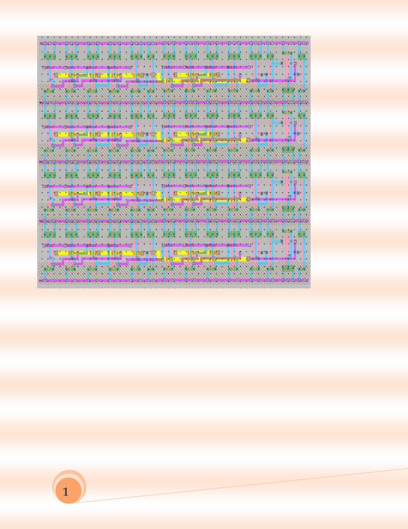
Laboratory Project
At the end of the lab, a final project of the lab is given to
the students, so that they might be able to encapsulate
the concepts gained during whole the laboratory
sessions. The project given to the students who have
taken the lab most recently was:
Layout of a 4-Bit Adder
The students had to draw the layout of the 4-bit
adder using Electric VLSI Design System and
verify it with simulator IRSIM.
DIG
ITA
L E
LE
CT
RO
NIC
S L
AB
OR
AT
OR
De
pa
rtme
nt o
f Ele
ctrical E
ng
ine
erin
g U
niv
ersity
of E
ng
ine
erin
g a
nd
Te
chn
olo
gy
La
ho
re
1
4