Embed Size (px)
Citation preview
Digital Parts of Receivers and Transmitters
Vilmos Rösner
• Digital Parts of Receivers
• Digital Parts of Transmitters
• Special Application: Bandpass Filter
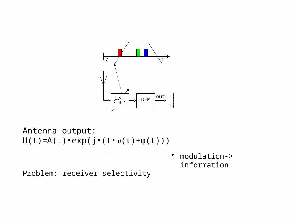
DEMout
f0
Antenna output: U(t)=A(t)•exp(j•(t•ω(t)+φ(t)))
modulation-> information
Problem: receiver selectivity

Superheterodyne Receiver (Edwin Armstrong 1918)
new problem: image rejection
DEMout
IF
f0f0
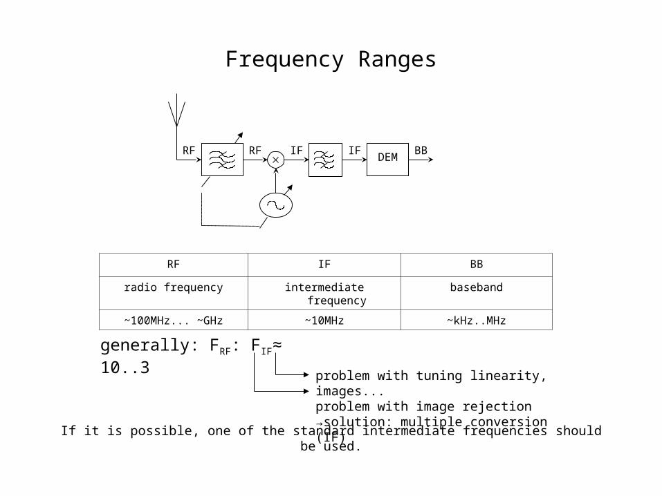
Frequency Ranges
DEMIFRF IF BBRF
RF IF BB
radio frequency intermediate frequency baseband
~100MHz... ~GHz ~10MHz ~kHz..MHz
generally: FRF: FIF≈ 10..3
problem with tuning linearity, images...problem with image rejection→solution: multiple conversion (IF)
If it is possible, one of the standard intermediate frequencies should be used.
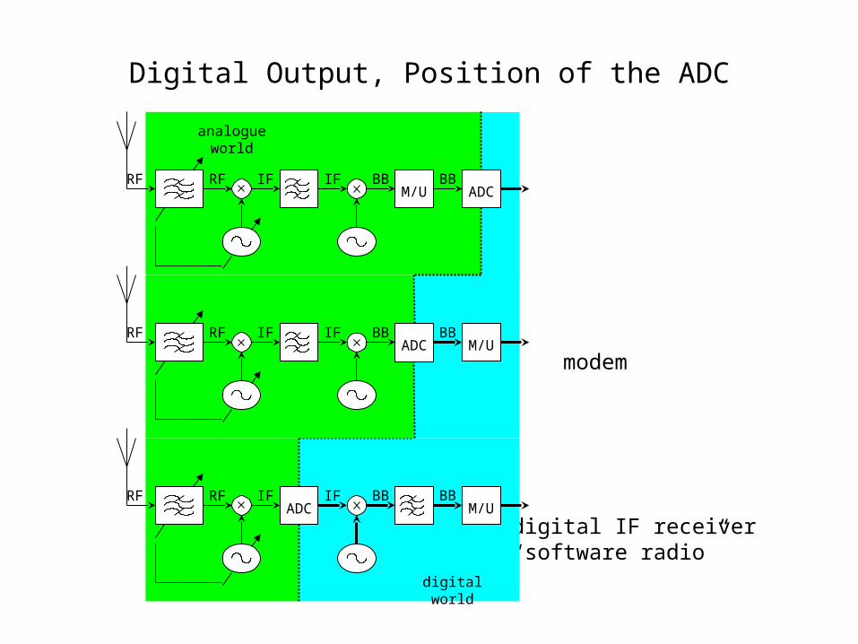
Digital Output, Position of the ADC
digital IF receiver“software radio”
modem
IF BB BBM/U
BBM/U
digital world
ADCIFRFRF
IFRF IF BBRFADC
IFRF IF BBRFADC
BBM/U
analogue world

Digital IF Receiver Components
• Analog to Digital Converter (ADC)• Digital Mixer (multiplier)• Digital Oscillator (NCO Numerically Controlled
Oscillator)• Digital Filter
DDC
outin
DDC
ADC FILTER
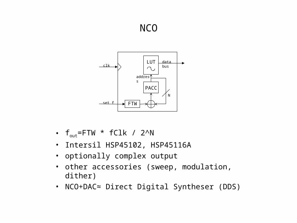
NCO
FTW
PACC
LUT
address
data bus
set f
clk
N
• fout=FTW * fClk / 2^N
• Intersil HSP45102, HSP45116A• optionally complex output• other accessories (sweep, modulation, dither)• NCO+DAC≈ Direct Digital Syntheser (DDS)
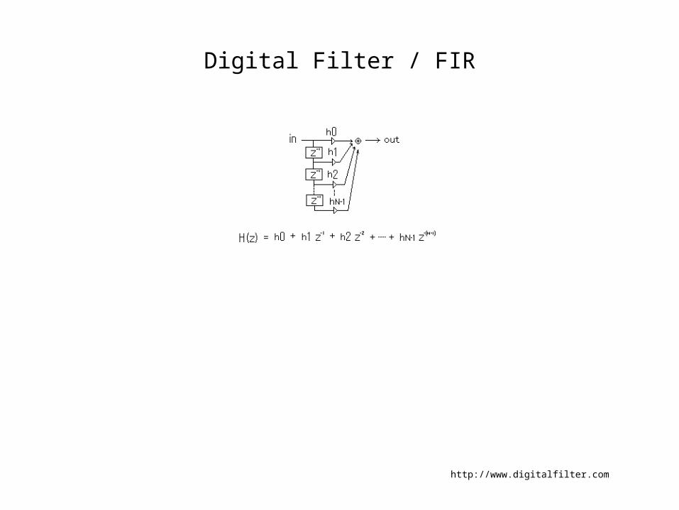
Digital Filter / FIR
http://www.digitalfilter.com
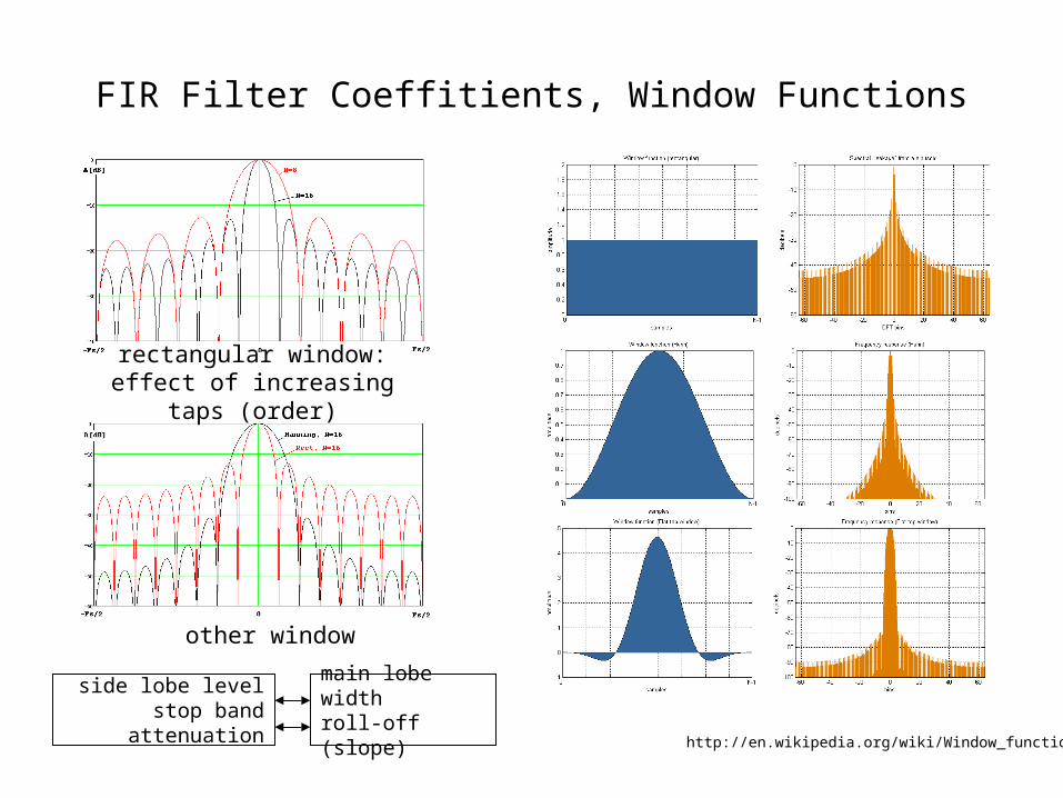
FIR Filter Coeffitients, Window Functions
rectangular window: effect of increasing taps (order)
other window
side lobe levelstop band attenuation
main lobe widthroll-off (slope)
http://en.wikipedia.org/wiki/Window_function
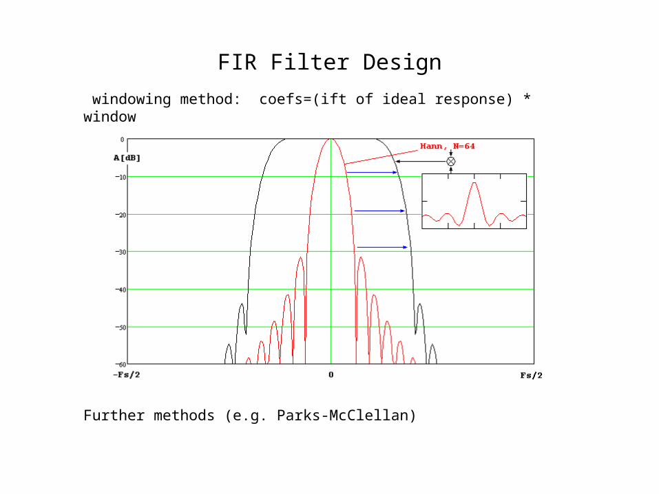
FIR Filter Design
windowing method: coefs=(ift of ideal response) * window
Further methods (e.g. Parks-McClellan)
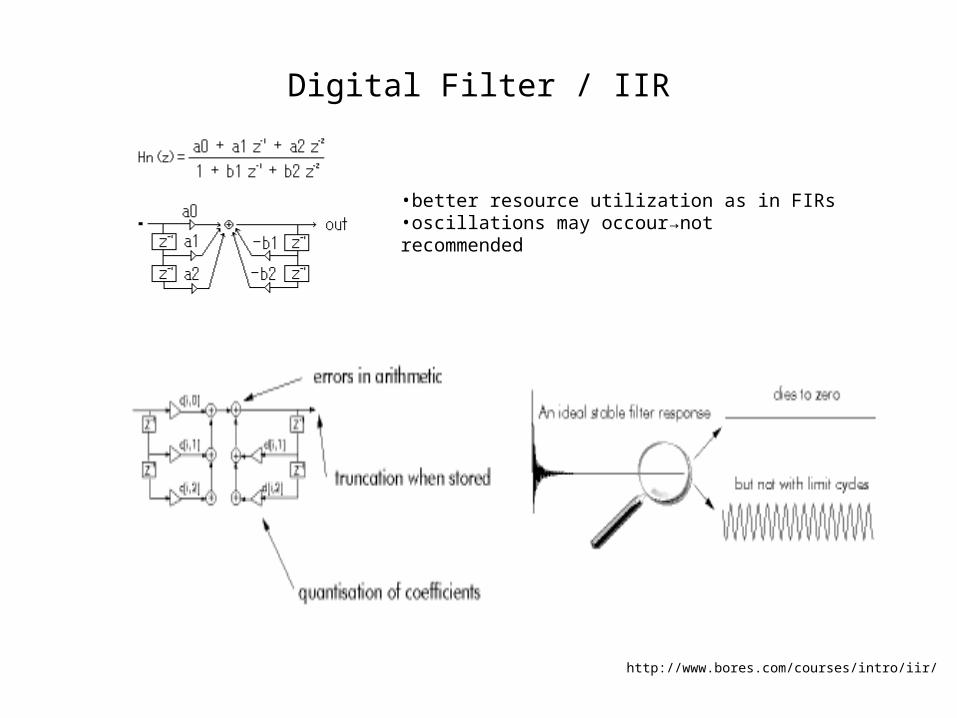
Digital Filter / IIR
•better resource utilization as in FIRs•oscillations may occour→not recommended
http://www.bores.com/courses/intro/iir/
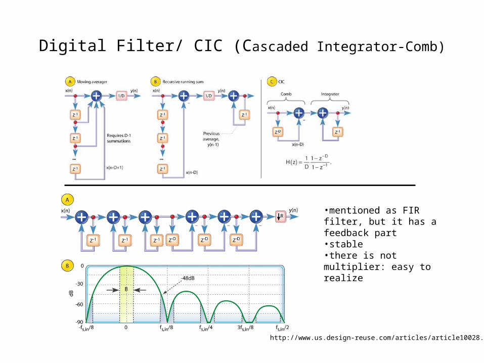
Digital Filter/ CIC (Cascaded Integrator-Comb)
•mentioned as FIR filter, but it has a feedback part•stable•there is not multiplier: easy to realize
http://www.us.design-reuse.com/articles/article10028.html
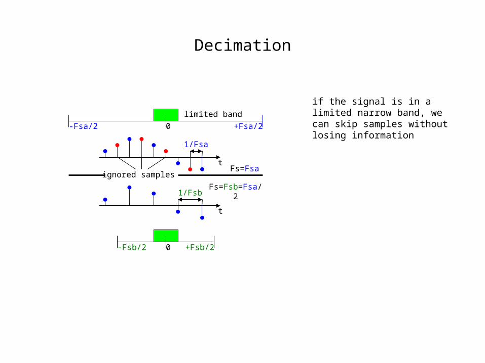
Decimation
if the signal is in a limited narrow band, we can skip samples without losing information
0 +Fsa/2-Fsa/2
0 +Fsb/2-Fsb/2
t
1/Fsa
ignored samples
t
1/Fsb
limited band
Fs=Fsa
Fs=Fsb=Fsa/2
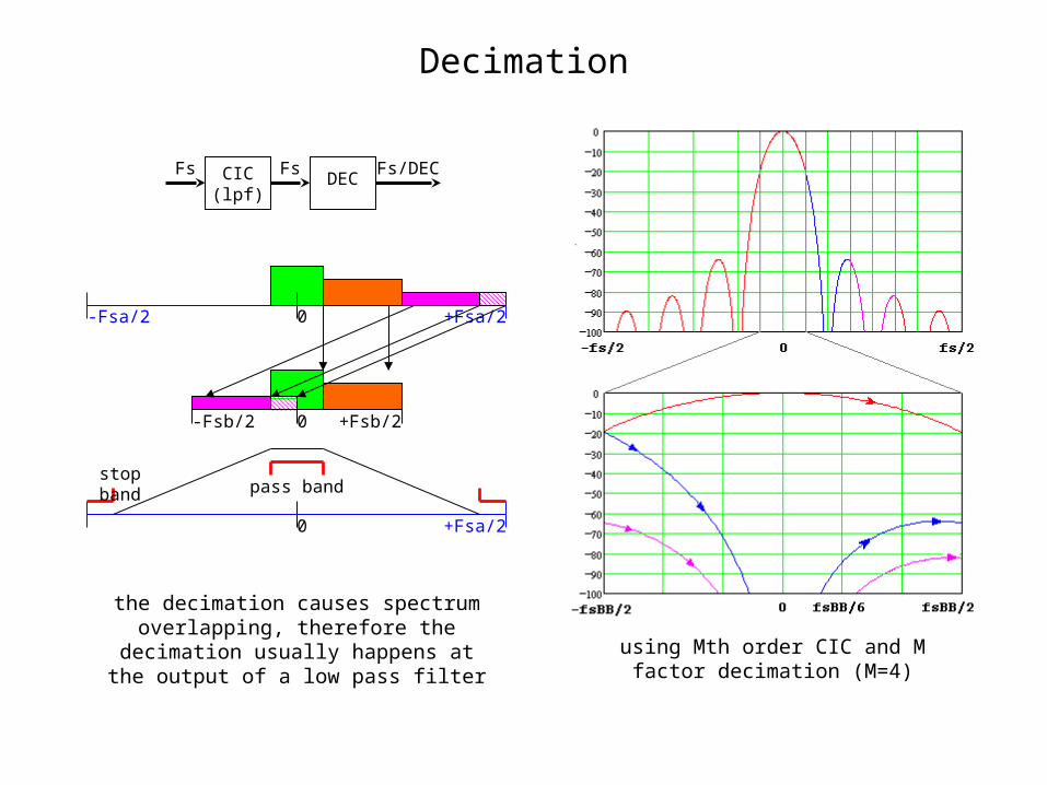
Decimation
0 +Fsa/2
0 +Fsb/2-Fsb/2
0 +Fsa/2
stop bandpass band
-Fsa/2
CIC(lpf)
FsFsDEC
Fs/DEC
the decimation causes spectrum overlapping, therefore the decimation usually happens at the output of a low
pass filter
using Mth order CIC and M factor decimation (M=4)
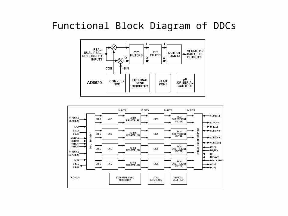
Functional Block Diagram of DDCs
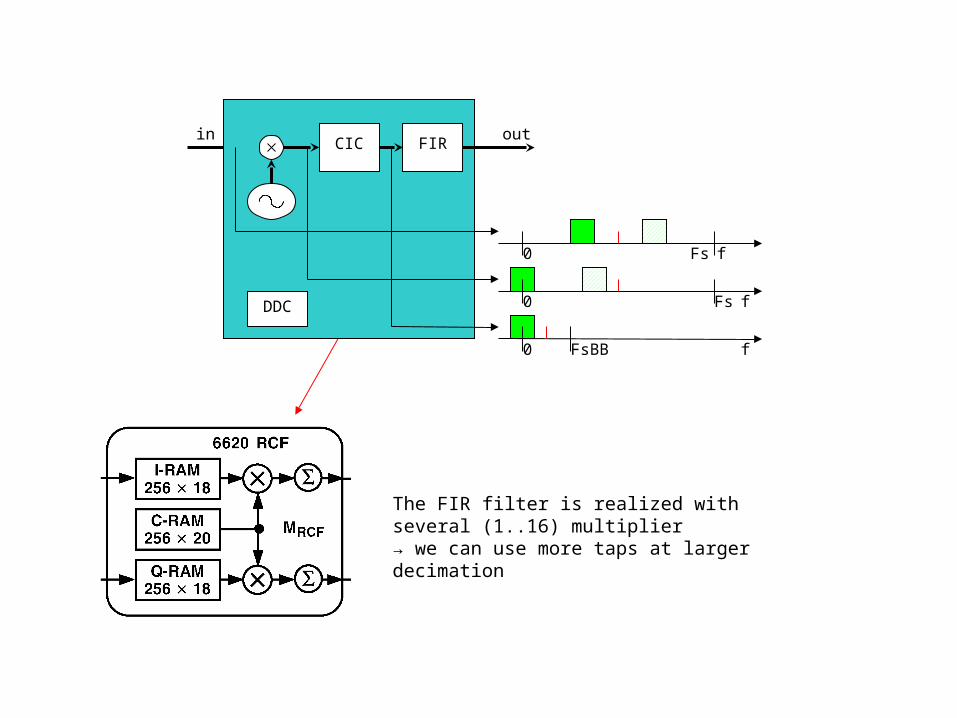
in out
f0 FsBB
f0 Fs
f0 Fs
CIC
DDC
FIR
The FIR filter is realized with several (1..16) multiplier→ we can use more taps at larger decimation

Example
in outCIC
DEC=16FIR
TAPS=16
64MHz 4MHz
in outCIC
DEC=32FIR
TAPS=32
64MHz 2MHz
• Two different settings of the same DDC• The decimation plays the similar role as down conversion in the analog techique
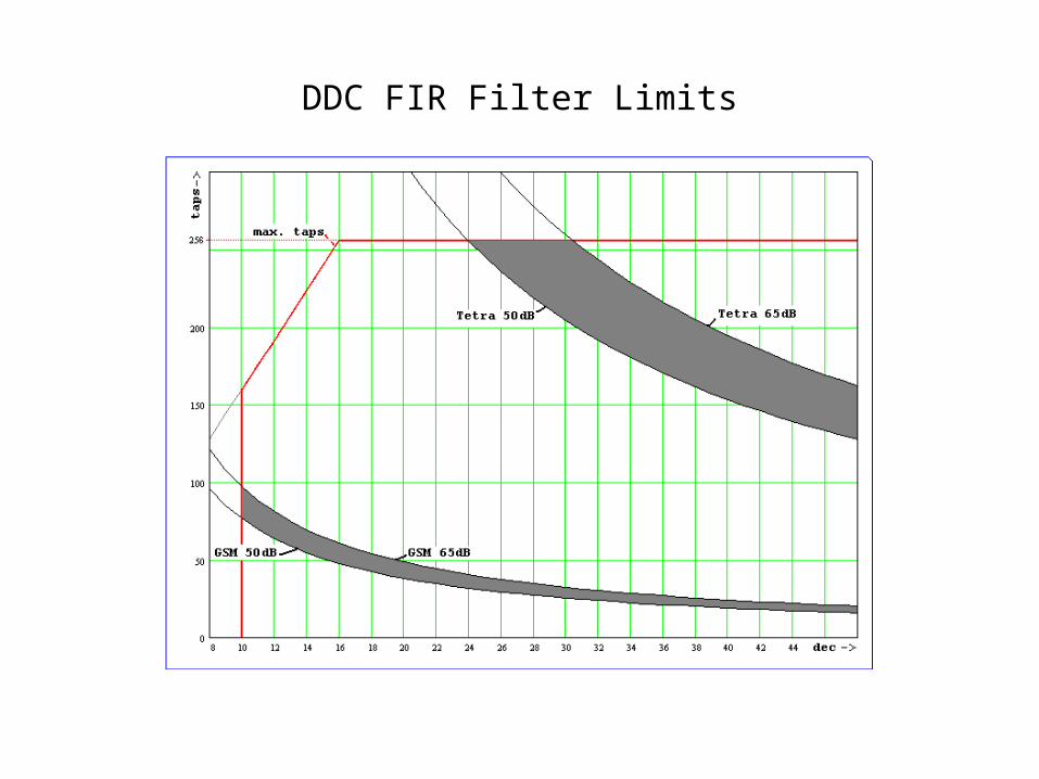
DDC FIR Filter Limits
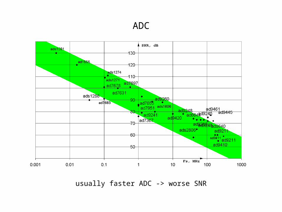
ADC
usually faster ADC -> worse SNR
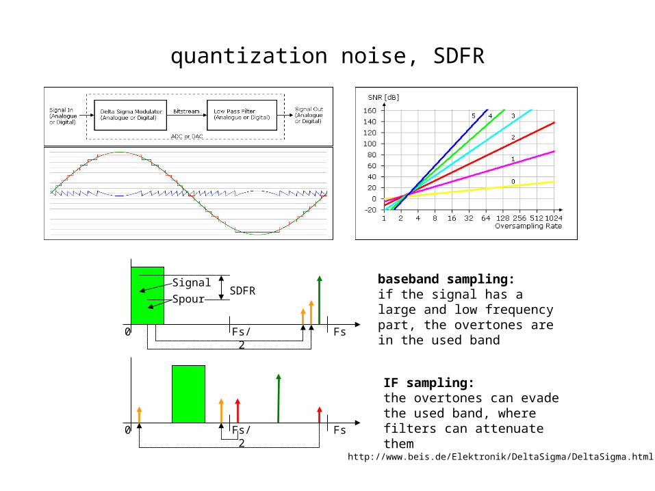
quantization noise, SDFR
0 Fs/2 Fs
Signal
Spour
0 Fs/2 Fs
SDFRbaseband sampling: if the signal has a large and low frequency part, the overtones are in the used band
IF sampling: the overtones can evade the used band, where filters can attenuate them
http://www.beis.de/Elektronik/DeltaSigma/DeltaSigma.html
Advantages of Digital IF
• easy to reproduce• thermal stability• flexibility• the output signal can be better as at BB sampling• accurate IQ output
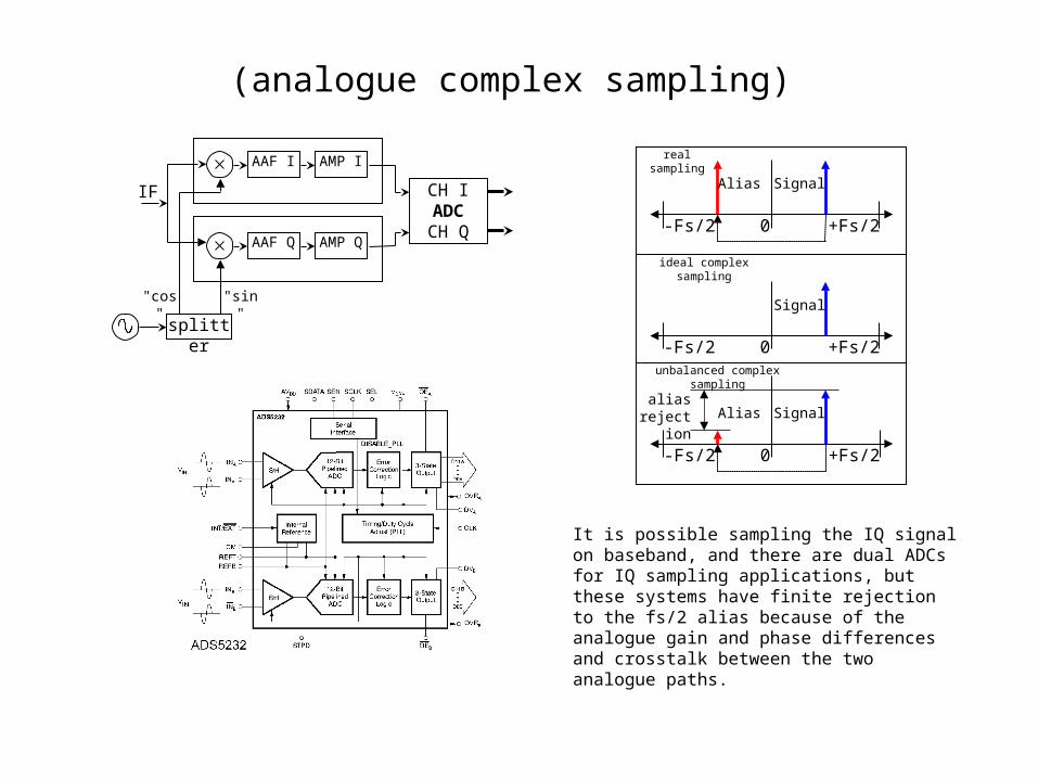
(analogue complex sampling)
IF CH IADCCH Q
AAF I AMP I
splitter
AAF Q AMP Q
"sin""cos"
0 +Fs/2
SignalAlias
-Fs/2
0 +Fs/2
Signal
-Fs/2
0 +Fs/2
SignalAlias
-Fs/2
real sampling
ideal complex sampling
unbalanced complex sampling
alias rejection
It is possible sampling the IQ signal on baseband, and there are dual ADCs for IQ sampling applications, but these systems have finite rejection to the fs/2 alias because of the analogue gain and phase differences and crosstalk between the two analogue paths.
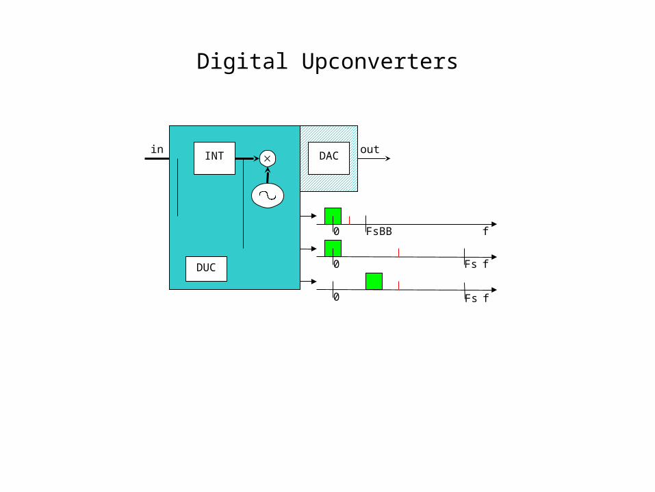
Digital Upconverters
f0 FsBB
f0 Fs
0
outinINT
DUC
DAC
fFs
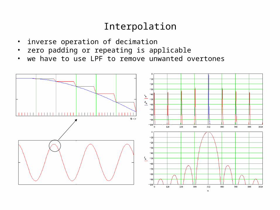
Interpolation
• inverse operation of decimation• zero padding or repeating is applicable• we have to use LPF to remove unwanted overtones
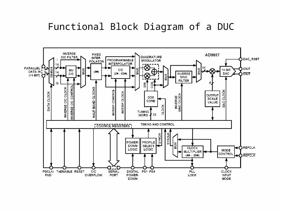
Functional Block Diagram of a DUC
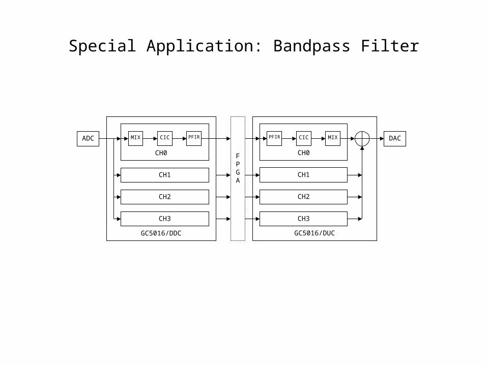
Special Application: Bandpass Filter
ADC CIC PFIRMIX
CH1
CH2
CH3
FPGA
GC5016/DDC
CH0
CICPFIR
CH1
CH2
CH3
GC5016/DUC
CH0
MIX DAC