Embed Size (px)
Citation preview
1
Digital QRP SWR/ Power MeterA KD1JV “Melt Solder” kit
Index:
DIGITAL QRP SWR/ POWER METER 1Features 2
OPERATION: 2
READING THE DISPLAY: 3
CONSTRUCTION: 4Parts list Error! Bookmark not defined.
CALIBRATION: 5
Transformer winding. 6Mounting the Transformer. 6
PACKAGING THE METER: 6
Alternative Packaging: 7Battery Life: 7Accuracy: 8
CONVERTING TO 7 SEGMENT LED DISPLAY: 9
CIRCUIT DESCRIPTION: 10
Diode compensation: 10Micro Controller: 11Schematic, Bride and Diode Compensation amp 12Controller and display schematic 12
Steven Weber633 Champlain StBerlin, NH 03570
[email protected]/kd1jv
2
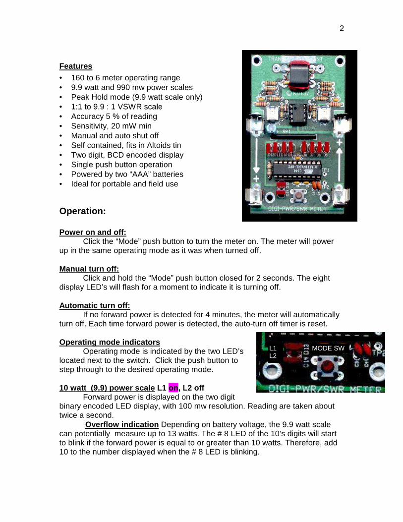
Features• 160 to 6 meter operating range• 9.9 watt and 990 mw power scales• Peak Hold mode (9.9 watt scale only)• 1:1 to 9.9 : 1 VSWR scale• Accuracy 5 % of reading• Sensitivity, 20 mW min• Manual and auto shut off• Self contained, fits in Altoids tin• Two digit, BCD encoded display• Single push button operation• Powered by two “AAA” batteries• Ideal for portable and field use
Operation:
Power on and off:Click the “Mode” push button to turn the meter on. The meter will power
up in the same operating mode as it was when turned off.
Manual turn off: Click and hold the “Mode” push button closed for 2 seconds. The eightdisplay LED’s will flash for a moment to indicate it is turning off.
Automatic turn off:If no forward power is detected for 4 minutes, the meter will automatically
turn off. Each time forward power is detected, the auto-turn off timer is reset.
Operating mode indicatorsOperating mode is indicated by the two LED’s
located next to the switch. Click the push button tostep through to the desired operating mode.
10 watt (9.9) power scale L1 on, L2 offForward power is displayed on the two digit
binary encoded LED display, with 100 mw resolution. Reading are taken abouttwice a second.
Overflow indication Depending on battery voltage, the 9.9 watt scalecan potentially measure up to 13 watts. The # 8 LED of the 10’s digits will startto blink if the forward power is equal to or greater than 10 watts. Therefore, add10 to the number displayed when the # 8 LED is blinking.
L1L2
MODE SW
3
990 mw power scale L1 off, L2 onThis scale reads in 10 mw increments. This mode is effectively a “display
shift,” displaying the 100 and 10 mw digits. Therefore, you can switch betweenthe 9.9 watt and 990 mw scales to see the extra digit of resolution.
Due to op amp input offset voltage and a software correction which ismade to the lower power readings, it is likely the 10 mW or possibly the 20 mWdigit will be lit when there is no forward power input.
Peak Hold L1 on, L2 onThis mode can be use with SSB transmitters to see your PEP output. In
peak hold mode, the readings are taken as quickly as possible and the highestpower measured is displayed. Peak readings are reset about two seconds after apeak has been detected.
VSWR L1 off, L2 off. VSWR is calculated using the formula (V forward + V reverse ) / (V forward - Vreverse.)Due to op amp offset, stray coupling and minor bridge imbalances, somereflected voltage will be detected, even when there is a perfect match. Therefore,the smallest VSWR indicated maybe 1.1 or 1.2, depending on the amount offorward power. VSWR reading with zero power input will also depend on op-ampoffsets. If reverse voltage is equal to or greater than forward voltage, the displaywill blank. If the forward voltage is greater than the reverse, the display willgenerally indicate a 1.0 VSWR, but it has been seen as high as 2.1. As soon asactual transmitter power is applied through the meter, the proper VSWR will bedisplayed. About 500 mW of forward power is required to get accurate VSWRreadings.
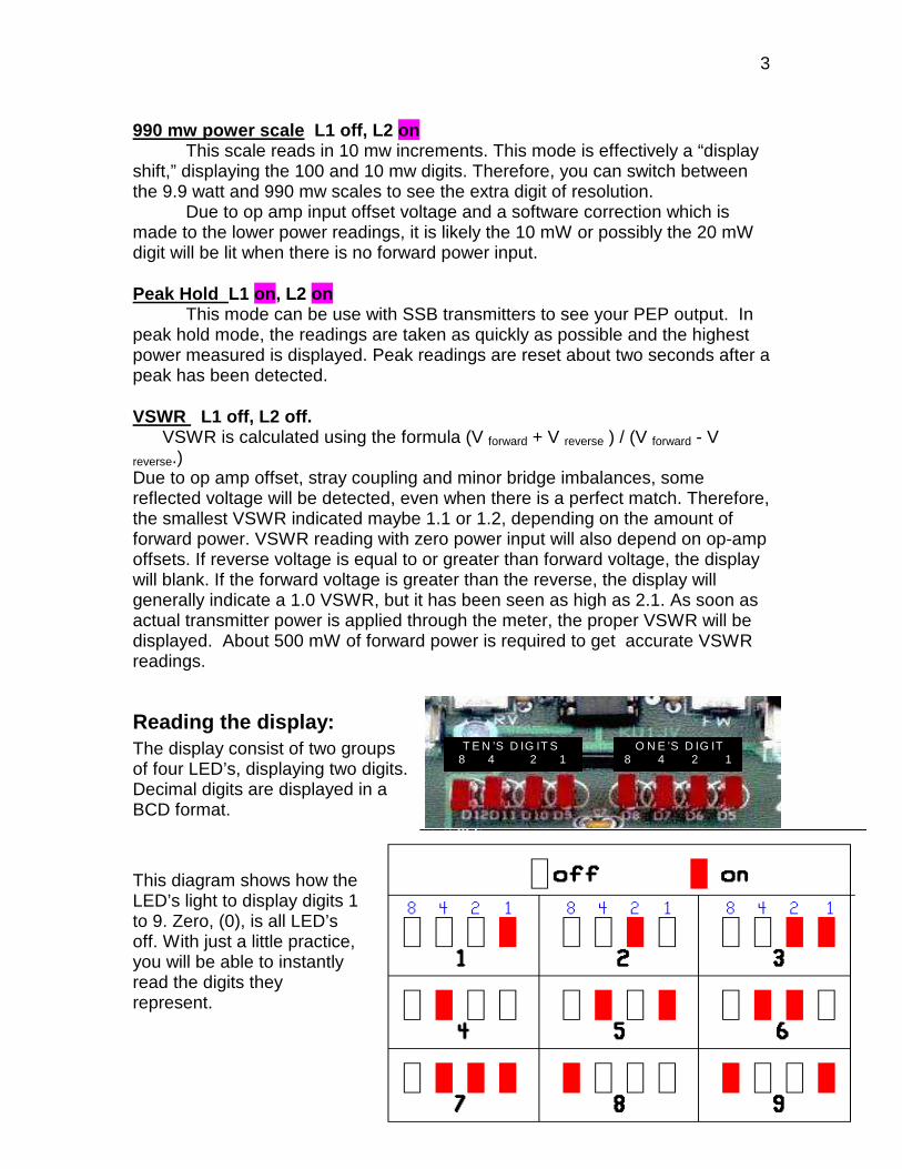
Reading the display:The display consist of two groupsof four LED’s, displaying two digits.Decimal digits are displayed in aBCD format.
This diagram shows how theLED’s light to display digits 1to 9. Zero, (0), is all LED’soff. With just a little practice,you will be able to instantlyread the digits theyrepresent.
T E N ’S D IG IT S 8 4 2 1
O N E ’S D IG IT 8 4 2 1
4
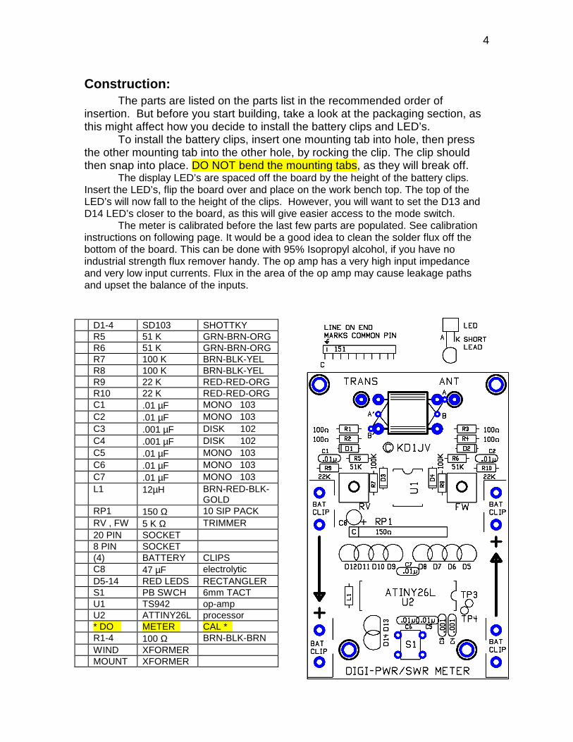
Construction:The parts are listed on the parts list in the recommended order of
insertion. But before you start building, take a look at the packaging section, asthis might affect how you decide to install the battery clips and LED’s.
To install the battery clips, insert one mounting tab into hole, then pressthe other mounting tab into the other hole, by rocking the clip. The clip shouldthen snap into place. DO NOT bend the mounting tabs, as they will break off.
The display LED’s are spaced off the board by the height of the battery clips.Insert the LED’s, flip the board over and place on the work bench top. The top of theLED’s will now fall to the height of the clips. However, you will want to set the D13 andD14 LED’s closer to the board, as this will give easier access to the mode switch.
The meter is calibrated before the last few parts are populated. See calibrationinstructions on following page. It would be a good idea to clean the solder flux off thebottom of the board. This can be done with 95% Isopropyl alcohol, if you have noindustrial strength flux remover handy. The op amp has a very high input impedanceand very low input currents. Flux in the area of the op amp may cause leakage pathsand upset the balance of the inputs.
D1-4 SD103 SHOTTKYR5 51 K GRN-BRN-ORGR6 51 K GRN-BRN-ORGR7 100 K BRN-BLK-YELR8 100 K BRN-BLK-YELR9 22 K RED-RED-ORGR10 22 K RED-RED-ORGC1 .01 µF MONO 103C2 .01 µF MONO 103C3 .001 µF DISK 102C4 .001 µF DISK 102C5 .01 µF MONO 103C6 .01 µF MONO 103C7 .01 µF MONO 103L1 12µH BRN-RED-BLK-
GOLDRP1 150 Ω 10 SIP PACKRV , FW 5 K Ω TRIMMER20 PIN SOCKET8 PIN SOCKET(4) BATTERY CLIPSC8 47 µF electrolyticD5-14 RED LEDS RECTANGLERS1 PB SWCH 6mm TACTU1 TS942 op-ampU2 ATTINY26L processor* DO METER CAL *R1-4 100 Ω BRN-BLK-BRNWIND XFORMERMOUNT XFORMER
5
Calibration:
• Before inserting the batteries to power up the board, take a few minutes todouble check your workmanship. Verify correct parts placement and look formissing solder connections or shorts. Also check the + battery terminals forshorts to ground. Shorted batteries get very hot!
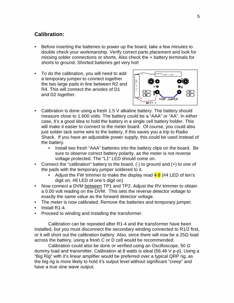
• To do the calibration, you will need to adda temporary jumper to connect togetherthe two large pads in line between R2 andR4. This will connect the anodes of D1and D2 together.
• Calibration is done using a fresh 1.5 V alkaline battery. The battery shouldmeasure close to 1.600 volts. The battery could be a “AAA” or “AA”. In eithercase, it’s a good idea to hold the battery in a single cell battery holder. Thiswill make it easier to connect to the meter board. Of course, you could alsojust solder tack some wire to the battery, if this saves you a trip to RadioShack. If you have an adjustable power supply, this could be used instead ofthe battery.
• Install two fresh “AAA” batteries into the battery clips on the board. Besure to observe correct battery polarity, as the meter is not reversevoltage protected. The “L1” LED should come on.
• Connect the “calibration” battery to the board, (-) to ground and (+) to one ofthe pads with the temporary jumper soldered to it.
• Adjust the FW trimmer to make the display read 4 8 (#4 LED of ten’sdigit on, #8 LED of one’s digit on)
• Now connect a DVM between TP1 and TP2. Adjust the RV trimmer to obtaina 0.00 volt reading on the DVM. This sets the reverse detector voltage toexactly the same value as the forward detector voltage.
• The meter is now calibrated. Remove the batteries and temporary jumper.• Install R1-4.• Proceed to winding and installing the transformer.
Calibration can be repeated after R1-4 and the transformer have beeninstalled, but you must disconnect the secondary winding connected to R1/2 first,or it will short out the calibration battery. Also, since there will now be a 25Ω loadacross the battery, using a fresh C or D cell would be recommended.
Calibration could also be done or verified using an Oscilloscope, 50 Ωdummy load and transmitter. Calibration at 8 watts is ideal (56.46 V p-p). Using a“Big Rig” with it’s linear amplifier would be preferred over a typical QRP rig, asthe big rig is more likely to hold it’s output level without significant “creep” andhave a true sine wave output.
6
Transformer winding.
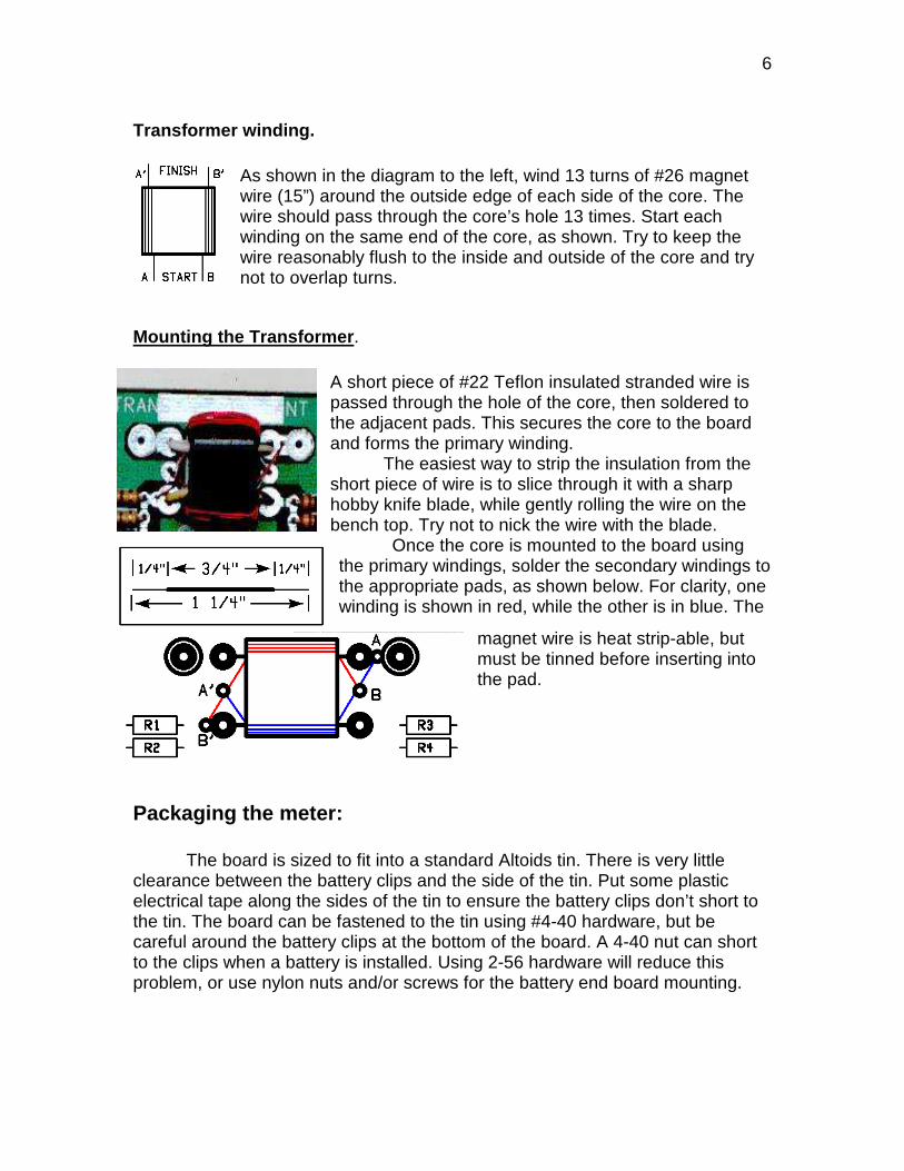
As shown in the diagram to the left, wind 13 turns of #26 magnetwire (15”) around the outside edge of each side of the core. Thewire should pass through the core’s hole 13 times. Start eachwinding on the same end of the core, as shown. Try to keep thewire reasonably flush to the inside and outside of the core and trynot to overlap turns.
Mounting the Transformer.
A short piece of #22 Teflon insulated stranded wire ispassed through the hole of the core, then soldered tothe adjacent pads. This secures the core to the boardand forms the primary winding.
The easiest way to strip the insulation from theshort piece of wire is to slice through it with a sharphobby knife blade, while gently rolling the wire on thebench top. Try not to nick the wire with the blade.
Once the core is mounted to the board usingthe primary windings, solder the secondary windings tothe appropriate pads, as shown below. For clarity, onewinding is shown in red, while the other is in blue. The
magnet wire is heat strip-able, butmust be tinned before inserting intothe pad.
Packaging the meter:
The board is sized to fit into a standard Altoids tin. There is very littleclearance between the battery clips and the side of the tin. Put some plasticelectrical tape along the sides of the tin to ensure the battery clips don’t short tothe tin. The board can be fastened to the tin using #4-40 hardware, but becareful around the battery clips at the bottom of the board. A 4-40 nut can shortto the clips when a battery is installed. Using 2-56 hardware will reduce thisproblem, or use nylon nuts and/or screws for the battery end board mounting.
7
There is just enough room for the end of aBNC jack between the top of the board and the sideof the tin. You may have to use two nuts, one oneither side of the tin wall, to mount the jack.
The ends of the BNC ground lugs need to besoldered to the board’s ground. A tined area justabove the transformer provides a place to solderthe lugs to. Resistor lead clippings can be used tojumper from the board to the center pin of the jack.
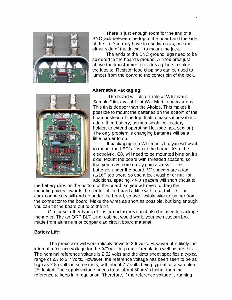
Alternative Packaging: The board will also fit into a “Whitman’s
Sampler” tin, available at Wal-Mart in many areasThis tin is deeper than the Altoids. This makes itpossible to mount the batteries on the bottom of theboard instead of the top. It also makes it possible toadd a third battery, using a single cell batteryholder, to extend operating life. (see next section)The only problem is changing batteries will be alittle harder to do.
If packaging in a Whitman’s tin, you will wantto mount the LED’s flush to the board. Also, theelectrolytic, C8, will need to be mounted lying on it’sside. Mount the board with threaded spacers, sothat you may more easily gain access to thebatteries under the board. ½” spacers are a tad(1/16”) too short, so use a lock washer or nut foradditional spacing. 4/40 spacers will short circuit to
the battery clips on the bottom of the board, so you will need to drag themounting holes towards the center of the board a little with a rat tail file. Thecoax connectors will end up under the board, so use flexible wire to jumper fromthe connector to the board. Make the wires as short as possible, but long enoughyou can tilt the board out to of the tin.
Of course, other types of tins or enclosures could also be used to packagethe meter. The amQRP BLT tuner cabinet would work, your own custom boxmade from aluminum or copper clad circuit board material.
Battery Life:
The processor will work reliably down to 2.6 volts. However, it is likely theinternal reference voltage for the A/D will drop out of regulation well before this.The nominal reference voltage is 2.52 volts and the data sheet specifies a typicalrange of 2.3 to 2.7 volts. However, the reference voltage has been seen to be ashigh as 2.85 volts in some units, with about 2.7 volts being typical for a sample of25 tested. The supply voltage needs to be about 50 mV’s higher than thereference to keep it in regulation. Therefore, if the reference voltage is running
8
on the high side, regulation will be marginal when the battery drops to 1.4 volts.As the battery voltage drops farther, the voltage reference will drop out ofregulation and the power calibration will change. This will be most pronounced athigher power readings, but readings will stay reasonably accurate at typical QRPpower levels up to 5 watts. VSWR is not affected, as this is calculated based onthe ratio of forward and reverse voltages.
Provided your packaging makes it possible, adding a third battery topower the meter will give longer operating life, brighter LED’s and ensure powermeasurement accuracy. It will also enable the meter to measure up to 16 watts.To add a third battery, cut the track connecting the two board mounted batteriesat the bottom of the board and insert the third battery there, using a single cellbattery holder to hold the new cell.
Yet another option is to use four batteries,. In this case, eliminate theboard mounted battery clips entirely and use a common four cell battery holder.A diode in series with the batteries will be required to drop the voltage slightly, asfour fresh batteries will slightly exceed the voltage rating for the processor. Thediode also has the benefit of adding reverse voltage protection.
When off, only a few micro amps of current is drawn by the processor andop-amp. Current will go up slightly when forward transmitter power is present, asthe op amp will be active and driving the diode compensation load resistor. If themeter is not to be used for extend periods of time, it is recommended to removethe batteries. Alternatively, you could slide a piece of paper card stock betweenone end of a battery and the battery clip to act as an on/off switch.
Accuracy:A meter of this type is only accurate when a true sine wave is being
detected. While this can generally be assumed, it is not always the case. An overdriven Class C amplifier can produce a distorted sine wave and possibly non-symmetrical output signal, even after it has gone through the low pass filter. Inthis case, the meter will indicate a power level somewhat higher than the truerms power. You must also be using a 50 Ω dummy load or have a 1:1 SWR.
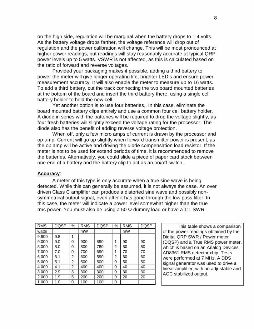
RMS DQSP % RMS DQSP % RMS DQSPwatts mW mW9.900 9.8 19.000 9.0 0 900 890 1 90 908.000 8.0 0 800 780 2 80 807.000 7.0 0 700 690 1 70 706.000 6.1 2 600 590 2 60 605.000 5.1 2 500 500 0 50 504.000 4.1 2 400 400 0 40 403.000 2.9 3 300 300 0 30 302.000 1.9 5 200 200 0 20 201.000 1.0 0 100 100 0
This table shows a comparisonof the power readings obtained by theDigital QRP SWR / Power meter(DQSP) and a True RMS power meter,which is based on an Analog DevicesAD8361 RMS detector chip. Testswere performed at 7 MHz. A DDSsignal generator was used to drive alinear amplifier, with an adjustable andAGC stabilized output.
9
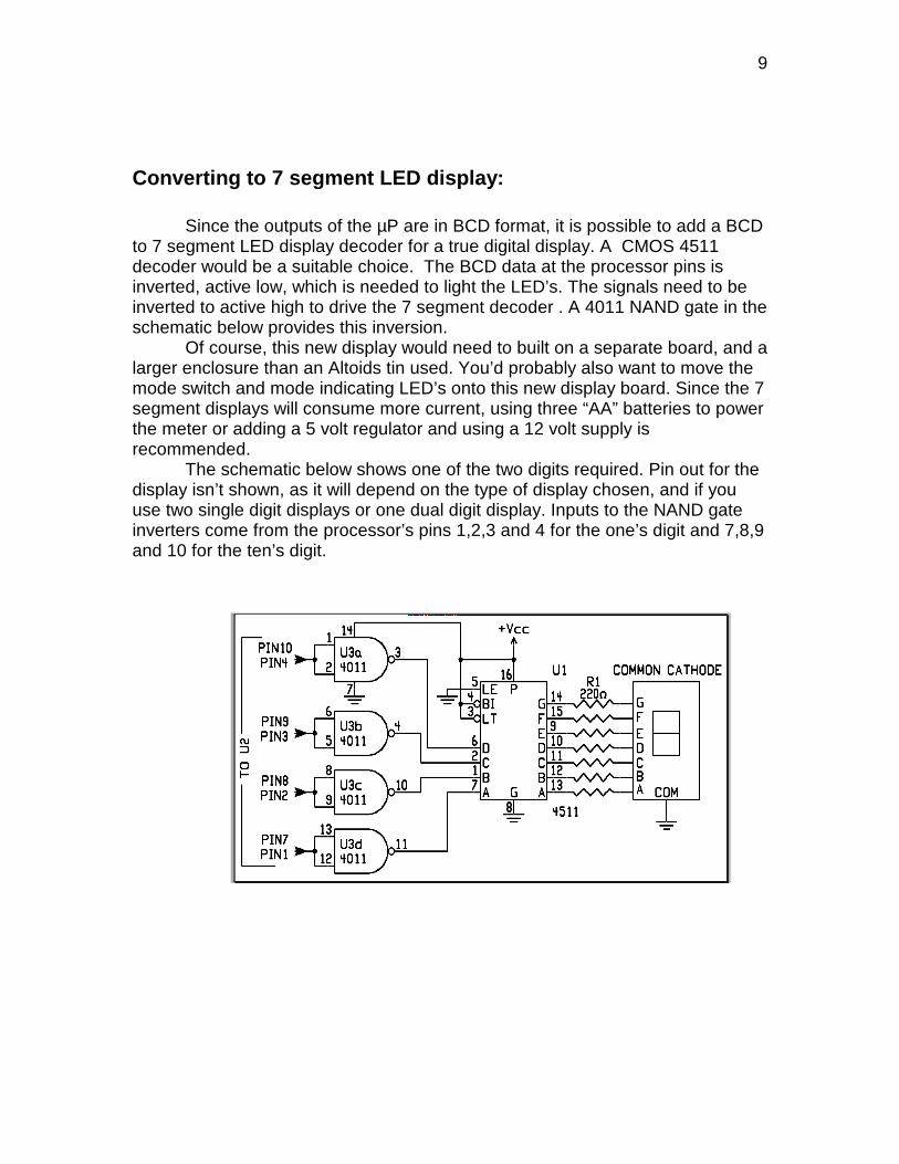
Converting to 7 segment LED display:
Since the outputs of the µP are in BCD format, it is possible to add a BCDto 7 segment LED display decoder for a true digital display. A CMOS 4511decoder would be a suitable choice. The BCD data at the processor pins isinverted, active low, which is needed to light the LED’s. The signals need to beinverted to active high to drive the 7 segment decoder . A 4011 NAND gate in theschematic below provides this inversion.
Of course, this new display would need to built on a separate board, and alarger enclosure than an Altoids tin used. You’d probably also want to move themode switch and mode indicating LED’s onto this new display board. Since the 7segment displays will consume more current, using three “AA” batteries to powerthe meter or adding a 5 volt regulator and using a 12 volt supply isrecommended.
The schematic below shows one of the two digits required. Pin out for thedisplay isn’t shown, as it will depend on the type of display chosen, and if youuse two single digit displays or one dual digit display. Inputs to the NAND gateinverters come from the processor’s pins 1,2,3 and 4 for the one’s digit and 7,8,9and 10 for the ten’s digit.
10
Circuit Description:
A classic “Stockton” directional coupler is used as a sensing element.What is somewhat unusual is the coupler is wound on a single binocular core,rather than two separate cores, which is most commonly done. What makes itpossible to use the binocular core is the fact there is very little coupling throughthe core between the two holes. There is some coupling between the secondarywindings, due to their close proximity to each other, but not enough to be aserious problem at the power levels this meter is meant to be used with.
Diode compensation:
Diode detectors have some problems which must be overcome in order tomake accurate voltage measurements. First, there is the inherent voltage dropacross them and the non-linear behavior of the diode at low levels. W7EL cameup with a clever circuit which does a good job of compensating for these diodedeficiencies.
By putting a diode in the feedback loop of a non-inverting amplifier, theoutput of the amplifier will mirror the actual input voltage of the detector diode.To be perfectly accurate, the current flowing into both the detector diode and thecompensation diode needs to be identical. In addition, both diodes should beperfectly matched. In practice, neither of these conditions can be entirelyensured.
The problem is that significant current only flows into the detector diodefor a few cycles, as the filter cap is being charged, and for half cycles at that,while current is always flowing into the compensation diode. The W7EL circuit,and that used in the OHR WM-2, uses a compensation diode load abut 10 timessmaller in value than the diode detector load. Tests using a WM-2 meter showedthis value was good at low power levels, but resulted in errors at higher powerlevels. It was found that making the compensation diode load twice as large asthe detector diode load brought the higher power readings in much closer towhat they should have been. However, the low level power readings developed asignificant amount of error. This was corrected by using a routine in softwarewhich calculates and adds a compensation value to the voltage reading beforepower is calculated.
There is one other artifact produced by the diode compensation amplifier,which has no real solution. This occurs when there is no voltage input to theamplifier from the detector diode. In this condition, the diode in the feedback loopof the op-amp appears to be a very large value resistor. This then causes theinput off set of the op-amp to be amplified, which in turn causes some minimalpower to be displayed by the Micro Controller.

11
Micro Controller:
An Atmel AVR series AT Tiny26L is used for the “brains” of the meter.This is a powerful micro-controller, which contains a 10 bit, 10 input channel A/Dconverter, 2 K of FLASH program memory, 128 bytes of EEPROM (which is notused in this application), 128 bytes of static RAM, a built in R/C clock, timers andover 100 instructions, most with true one clock cycle execution.
Two of the multi-channel 10 bit A/D converter ports are used to input thedetector voltages for processing. The forward voltage is multiplied by four forscaling. This sets the full scale equivalent to 4048 counts, or 40.48 volts whenscaled to the input voltage seen at the antenna terminal. The maximum powerwhich can then be measured is then 16 watts.
Power is calculated by squaring the peak forward voltage and thendividing by 100. This formula isn’t as precise as rms voltage squared, thendivided by 50, but is close enough given the overall accuracy of the meter. Theabove calculation is done in binary to 32 bit precision. The results are thenconverted into packed BCD and outputted to the display LED’s.
Supply voltage to the analog circuits inside the micro controller is suppliedthrough a L/C low pass filter to reduce digital noise from getting into the A/Dconverter. In addition, the core of the processor is put into “Sleep Mode” during aconversion, which also improves the accuracy of the conversion by reducingnoise generated internally of the processor.
12
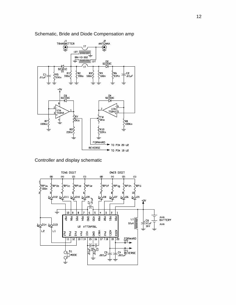
Schematic, Bride and Diode Compensation amp
Controller and display schematic