Embed Size (px)
Citation preview
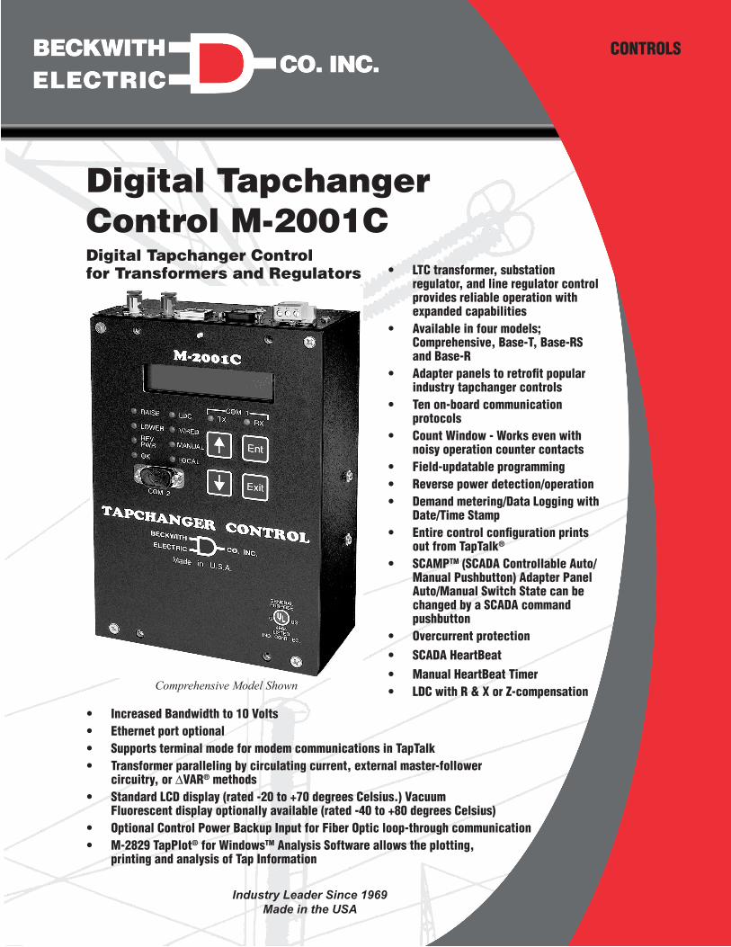
Digital Tapchanger Control M-2001C
CONTROLS
• LTC transformer, substation regulator, and line regulator control provides reliable operation with expanded capabilities
• Available in four models; Comprehensive, Base-T, Base-RS and Base-R
• Adapter panels to retrofit popular industry tapchanger controls
• Ten on-board communication protocols
• Count Window - Works even with noisy operation counter contacts
• Field-updatable programming • Reverse power detection/operation • Demand metering/Data Logging with
Date/Time Stamp • Entire control configuration prints
out from TapTalk®
• SCAMPTM (SCADA Controllable Auto/Manual Pushbutton) Adapter Panel Auto/Manual Switch State can be changed by a SCADA command pushbutton
• Overcurrent protection • SCADA HeartBeat • Manual HeartBeat Timer • LDC with R & X or Z-compensation
Digital Tapchanger Control for Transformers and Regulators
Comprehensive Model Shown
• Increased Bandwidth to 10 Volts • Ethernet port optional • Supports terminal mode for modem communications in TapTalk • Transformer paralleling by circulating current, external master-follower
circuitry, or ∆VAR® methods • Standard LCD display (rated -20 to +70 degrees Celsius.) Vacuum
Fluorescent display optionally available (rated -40 to +80 degrees Celsius) • Optional Control Power Backup Input for Fiber Optic loop-through communication • M-2829 TapPlot® for WindowsTM Analysis Software allows the plotting,
printing and analysis of Tap Information
Industry Leader Since 1969Made in the USA
–2–
M‑2001C Digital Tapchanger Control
Comprehensive Version FeaturesThe Comprehensive version includes all M-2001C features and can be used for LTCs or regulators where SCADA communications are desired.
• Adjustable Bandcenter
• Adjustable Bandwidth
• Line Drop Compensation, R and X Compensation
• Time Delay, Definite and Inverse
• InterTap Time Delay
• Selectable Outputs, Continuous or Pulsed
• Reverse Power Operation, for Transformer LTC and Single-Phase Regulator applications
• CT to VT Phasing Correction
• Real-Time Metering of measured and calculated parameters
• Demand Metering with selectable time interval
• Drag Hands Operation
• Adjustable Line Overcurrent Tapchange Inhibit
• Voltage Limits
• Tap Position Limits
• Runback
• Three independent Voltage Reduction Steps
• Sequential and Non-Sequential Operation
• SCADA HeartBeat
• Manual HeartBeat Timer
• VT Ratio Correction
• Self-Test Alarm Output Contacts
• User Programmable Alarm Contacts
• Operations Counter
• Resettable Operations Counter
• Harmonic Analysis through TapTalk®
• Tap Position Record
• Auto/Off/Manual Switch Status
• A or B Regulator Type Selection
• Alarm Contact Outputs (2)
• Control Voltage Input
• Motor Power Input
• Line Current Input
• Raise Output
• Lower Output
• 20 Character by 2 Row LCD Display
• Tap Position Knowledge by:
– Contact KeepTrack™
– Shaft Coupled KeepTrack™
– Resistor Divider KeepTrack™
– Motor Direct Drive KeepTrack™
• M-2029A TapTalk Communications Software
• M-2829 TapPlot® Tap Analysis Software
• Adapter Panel Auto/Manual Switch Type Selection
• Front RS-232 Communications Port COM2
• External Inhibit of Auto Tapchange
• Circulating Current Paralleling Method
• Front Panel LEDs for Out-of-Band Raise, Out-of-Band Lower, Reverse Power Flow Rev Pwr Detected, CPU OK, Line Drop Compensation LDC In Effect, Voltage Reduction V/RED in Effect, Auto Operation Block MANUAL, SCADA Control blocked LOCAL and Com1 TX and RX.
• Circulating Current Input
• Voltage Reduction 1 & 2 Inputs (Binary) (3 Steps Total)
• Neutral Position Detect (Binary)
• Counter Input (Binary)
• Seal-in/Switch Status Input (Binary)
• Non-Sequential/SCADA Block Input (Binary)
• Seal-in Output
• COM1 (top) RS-232, RS-485 and Fiber Optics
• Communication Protocols include BECO 2200, BECO 2179, Cooper 2179, Cooper 2179A, GP-2179, GP DNP3.0, DNP3.0, AL PWR DNP3.0, MISS PWR DNP3.0 and MODBUS.
Comprehensive Optional Features • Paralleling ∆VAR® Methods
• Vacuum Fluorescent Display (rated -40 to +80 degrees Celsius.)
• Ethernet Port COM3 (10 Mpbs) is available through an RJ-45 jack on the top of the control. This port supports DNP over TCP/IP, BECO 2200 over TCP/IP, and MODBUS over TCP/IP.
• Control Power Back-Up Input – input (+12 Vdc) for backup of Fiber Optic loop-through communication
Comprehensive Accessories • M-2025B(D) Cur ren t Loop In te r face
Module-Current-To-Voltage analog converter for tap position sensors
• M-2026 AC-DC Control Power Backup Supply
• M-2027 Control Power Backup Supply - AC Only
• M-2948 Tap Position Sensor
–3–
M‑2001C Digital Tapchanger Control
Base-T Version FeaturesThe Base-T version of the M-2001C is designed for transformers. It uses one COMM port (Com2) for communications.
• Adjustable Bandcenter
• Adjustable Bandwidth
• Line Drop Compensation, R and X Compensation
• Time Delay, Definite and Inverse
• InterTap Time Delay
• Selectable Outputs, Continuous or Pulsed
• Reverse Power Operation, for Transformer LTC and Single-Phase Regulator applications
• CT to VT Phasing Correction
• Real-Time Metering of measured and calculated parameters
• Demand Metering with selectable time interval
• Drag Hands Operation
• Adjustable Line Overcurrent Tapchange Inhibit
• Voltage Limits
• Tap Position Limits
• Runback
• Three independent Voltage Reduction Steps
• Sequential and Non-Sequential Operation
• VT Ratio Correction
• Self-Test Alarm Output Contacts
• User Programmable Alarm Contacts
• Operations Counter
• Resettable Operations Counter
• Harmonic Analysis through TapTalk®
• Tap Position Record
• Auto/Off/Manual Switch Status
• A or B Regulator Type Selection
• Alarm Contact Outputs (2)
• Control Voltage Input
• Motor Power Input
• Line Current Input
• Raise Output
• Lower Output
• Tap Position Knowledge by:
– Contact KeepTrack™
– Shaft Coupled KeepTrack™
– Resistor Divider KeepTrack™
– Motor Direct Drive KeepTrack™
• 20 Character by 2 Row LCD Display
• M-2029A TapTalk Communications Software
• M-2829 TapPlot® Tap Analysis Software
• Front Panel LEDs for Out-of-Band Raise, Out-of-Band Lower, Reverse Power Flow Rev Pwr Detected, CPU OK, Line Drop Compensation LDC In Effect, Voltage Reduction V/RED in Effect and Auto Operation block MANUAL (LOCAL and Com1 TX and RX LEDs are NOT functional on BASE-T Versions).
• Includes BECO 2200 protocol on COM2 port
• Circulating Current Paralleling Method
• Front RS-232 Communications Port COM2
• External inhibit of Auto Tapchange (non-sequential)
• Circulating Current Input
• Voltage Reduction 1 & 2 Inputs (Binary) (3 Steps Total)
• Neutral Position Detect (Binary)
• Counter Input (Binary)
• Seal-in/Switch Status Input (Binary)
• Non-sequential/SCADA Block Input (Binary)
• Seal-in Output
Base-T Optional Features • Vacuum Fluorescent Display (rated -40 to +80
degrees Celsius.)
• ∆VAR® Paralleling Methods
• Control Power Back-Up Input – input (+12 Vdc) for backup of Fiber Optic loop-through communication
Base-T Accessories • M-2025B(D) Current Loop Interface Module-
Current-To-Voltage analog converter for tap position sensors
• M-2026 AC-DC Control Power Backup Supply
• M-2027 Control Power Backup Supply - AC Only
• M-2948 Tap Position Sensor
–4–
M‑2001C Digital Tapchanger Control
Base-RS Version FeaturesThe Base-RS version of the M-2001C is designed pri-marily for regulators, but can also be applied to LTCs where SCADA communication is required. It provides one SCADA COMM port (COM1) as either an optional RS-485 or fiber optics port for communications.
• Adjustable Bandcenter
• Adjustable Bandwidth
• Line Drop Compensation, R and X Compensation
• Time Delay, Definite and Inverse
• InterTap Time Delay
• Selectable Outputs, Continuous or Pulsed
• Reverse Power Operation, for Transformer LTC and Single-Phase Regulator applications
• CT to VT Phasing Correction
• Real-Time Meter ing of measured and calculated parameters
• Demand Metering with selectable time interval
• Drag Hands Operation
• Adjustable Line Overcurrent Tapchange Inhibit
• Voltage Limits
• Tap Position Limits
• Runback
• Self-Test Alarm Output Contacts
• Three independent Voltage Reduction Steps
• Sequential and Non-Sequential Operation
• SCADA HeartBeat
• Manual HeartBeat Timer
• VT Ratio Correction
• Tap Position Knowledge by Motor Direct Drive KeepTrack™ method
• Operations Counter
• Resettable Operations Counter
• Harmonic Analysis through TapTalk®
• Tap Position Record
• Auto/Off/Manual Switch Status
• A or B Regulator Type Selection
• Control Voltage Input
• Motor Power Input
• Line Current Input
• Raise Output
• Lower Output
• 20 Character by 2 Row LCD Display
• M-2029A TapTalk Communications Software
• M-2829 TapPlot® Tap Analysis Software
• Adapter Panel Auto/Manual Switch Type Selection
• Front Panel LEDs for Out-of-Band Raise, Out-of-Band Lower, Reverse Power Flow Rev Pwr Detected, CPU OK, Line Drop Compensation LDC In Effect, Voltage Reduction V/RED in Effect, Auto Operation Block MANUAL, SCADA Control blocked LOCAL and Com1 TX and RX.
• Includes BECO 2200 protocol on COM2 port
• Front RS-232 Communications Port COM2
• Voltage Reduction 1 & 2 Inputs (Binary) (3 Steps Total)
• Non-Sequential/SCADA Block Input (Binary)
• Neutral Position Detect (Binary)
• Counter Input (Binary)
• Seal-in/Switch Status Input (Binary)
• Seal-in Output
• Communication Protocols include BECO 2200, BECO 2179, Cooper 2179, Cooper 2179A, GP-2179, GP DNP3.0, DNP3.0, AL PWR DNP3.0, MISS PWR DNP3.0 and MODBUS.
Base-RS Optional Features • Vacuum Fluorescent Display (rated -40 to +80
degrees Celsius.)
• Control Power Back-Up Input – input (+12 Vdc) for backup of Fiber Optic loop-through communication
• COM1 (top) RS-485 or Fiber Optics
Base-RS Accessories • M-2026 AC-DC Control Power Backup Supply
• M-2027 Control Power Backup Supply - AC Only
–5–
M‑2001C Digital Tapchanger Control
Base-R Version FeaturesThe Base-R version of the M-2001C is designed primarily for regulators, but can also be applied to LTCs where no SCADA communication is required. It uses one COMM port (COM2) for communications.
• Adjustable Bandcenter
• Adjustable Bandwidth
• Line Drop Compensation, R and X Compensation
• Time Delay, Definite and Inverse
• InterTap Time Delay
• Selectable Outputs, Continuous or Pulsed
• Reverse Power Operation, for Transformer LTC and Single-Phase Regulator applications
• CT to VT Phasing Correction
• Real-Time Metering of measured and calculated parameters
• Demand Metering with selectable time interval
• Drag Hands Operation
• Adjustable Line Overcurrent Tapchange Inhibit
• Voltage Limits
• Tap Position Limits
• Runback
• Three independent Voltage Reduction Steps
• Sequential Operation
• VT Ratio Correction
• Tap Position Knowledge by Motor Direct Drive KeepTrack™ method
• Operations Counter
• Resettable Operations Counter
• Harmonic Analysis through TapTalk®
• Tap Position Record
• Auto/Off/Manual Switch Status
• A or B Regulator Type Selection
• Control Voltage Input
• Motor Power Input
• Line Current Input
• Raise Output
• Lower Output
• 20 Character by 2 Row LCD Display
• M-2029A TapTalk Communications Software
• M-2829 TapPlot® Tap Analysis Software
• Front Panel LEDs for Out-of-Band Raise, Out-of-Band Lower, Reverse Power Flow Rev Pwr Detected, CPU OK, Line Drop Compensation LDC In Effect, Voltage Reduction V/RED in Effect and Auto Operation block MANUAL (LOCAL and Com1 TX and RX LEDs are NOT functional on BASE-R Versions).
• Includes BECO 2200 protocol on COM2 port
• Front RS-232 Communications Port COM2
• Voltage Reduction 1 & 2 Inputs (Binary) (3 Steps Total)
• Neutral Position Detect (Binary)
• Counter Input (Binary)
• Seal-in/Switch Status Input (Binary)
• Seal-in Output
Base-R Optional Features • Vacuum Fluorescent Display (rated -40 to +80
degrees Celsius.)
• Control Power Back-Up Input – input (+12 Vdc) for backup of Fiber Optic loop-through communication
Base-R Accessories • M-2026 AC-DC Control Power Backup Supply
• M-2027 Control Power Backup Supply - AC Only
–6–
M‑2001C Digital Tapchanger Control
Features NOTE: Not all features are included in all versions.
Bandcenter: Adjustable from 100 V to 135 V in 0.1 V increments.
Bandwidth: Adjustable from 1 V to 10 V in 0.1 V increments.
Line Drop Compensation: R and X compensation. Adjustable from -24 V to +24 V in 1 V increments. Z compensation available with adjustment of voltage raise from 0 V to +24 V, in increments of 1 V.
Time Delay: Definite; adjustable from 1 second to 120 seconds, in 1 second increments. Inverse; adjustable from 1 second to 120 seconds, in 1 second increments.
InterTap Time Delay: Used to introduce time delay between tap operations when control is in sequential mode; adjustable from 0 to 60 seconds in 1.0 second increments. Counter input required.
Selectable Outputs: Continuous or pulsed. Normally, an output (raise or lower) signal is maintained when the voltage remains outside the band. A pulsed output length is programmable from 0.2 to 12 seconds, in increments of 0.1 second.
Reverse Power Operation: Transformer LTC Application: Can be set to Ignore, Block, Regulate Rev, Return To Neutral or Distributed Generation operation with reverse power (when using positive tap position knowledge).
Single‑Phase Regulators: If Motor Direct Drive KeepTrack™ is applicable, unit may be set to "Return to Neutral" or "Regulate Reverse". The Regulate Reverse feature allows separate setpoints and regulation in the reverse direction without the installation of source-side VTs, otherwise it can be set to Ignore, Block or Distributed Generation.
CT to VT Phasing Correction: Adjustable from 0° to +330° in 30° increments.
Real-Time Metering: The following measured and calculated values are available in real-time:
• Local Voltage
• Load kVA, or MVA
• Load Center Voltage (Compensated Voltage)
• Load kW, or MW
• Line Current
• Load kVAr, or MVAr
• Power Factor
• Line Frequency
Demand Metering: Time interval selected as 15, 30, or 60 minutes.
Drag Hands Operation: The following "drag-hand" values are stored with date and time stamping and are averaged over 32 seconds:
• Minimum Local Voltage
• Maximum Local Voltage
The following "drag-hand" values are stored with date and time stamping and are calculated over the demand time interval (15, 30, or 60 minutes) as selected by the user:
• Maximum Primary Line Current
• Maximum Load kW, or MW
• Maximum Load kVAr, or MVAr
• Maximum Load kVA, or MVA (and Power Factor at time of Maximum Load kVA, or MVA)
–7–
M‑2001C Digital Tapchanger Control
Line Overcurrent Tapchange Inhibit: Adjustable from 200 mA to 640 mA of line current for 200 mA CT or 1.0 A to 3.2 A for 1 A CT display and 5.0 A to 16.0 A for 5 A CT display. External auxiliary CT required for 1.0 A and 5 A CT inputs.
Voltage Limits, Tap Position Limits, and Runback: Overvoltage and Undervoltage limits are independently adjustable from 95 V to 135 V in 0.1 V increments. Upper and lower tap position limits may be set by user, with tap position knowledge active. An adjustable deadband (above the overvoltage limit) of 1 V to 4 V is available, which is used to set the runback limit.
Voltage Reduction: Three independent steps, each adjustable from 0% to 10% in 0.1% increments of the bandcenter setpoint. Also included is a Voltage Reduction Turn Off Timer feature that when the timer is set from 1 to 999 minutes (0 minutes = disabled), it will turn off any Voltage Reduction invoked (via Comms) after the time expires.
Inhibit of Auto Tapchange: Blocks automatic tapchanger operation in response to external contact closure or software setting.
Sequential or Non-Sequential Operation: Non-sequential operation resets the time delay upon momentary external contact closure at the non-sequential input.
Paralleling Methods:
Circulating Current: The circulating current method is standard, and may be implemented using separate balancing equipment such as the Beckwith Electric M-0115A Parallel Balancing Module. Consult with factory for use with existing external master-follower circuitry.
∆VAR®: When specified, the ∆VAR1 method may be implemented by using separate balancing equipment such as the M-0115A Balancing Module. The ∆VAR2 method does not require the use of the M-0115A Balancing Module and is only applicable when paralleling two transformers.
For all methods of paralleling except ∆VAR2, overcurrent protection, such as that provided by the M-0127A Overcurrent Relay, is recommended.
VT Ratio Correction: VT correction from -15 V to +15 V in 0.1 V increments.
Self-Test Alarm Output Contacts: Alerts operator to loss of power or malfunction of control. When the control is configured for SCAMP Pushbutton Auto/Manual Switch Type, this output is not available.
User-Programmable Alarm Contacts: Alerts operator to one or more of the following system conditions: Communications Block Invoked, Block Raise Voltage Limit Exceeded, Block Lower Voltage Limit Exceeded, Voltage Reduction (any step) Invoked, Reverse Power Flow Condition Detected, Line Current Limit Exceeded, Tap Block Raise in Effect, and Tap Block Lower in Effect.
Tap Position KnowledgeTransformer LTC: The optional M-2025B(D) Current Loop Interface Module receives a tap position signal from a tap position sensor (M-2948) or Incon 1250B Rotary Position Sensor and outputs to the M-2001C through a bottom port.
Single‑Phase Regulators: In most applications, tap position information can be maintained by means of Motor Direct Drive KeepTrack™ logic.
Operations Counter: A software counter increments by one count per either an open/close/open contact operation (X1) or an open/close or close/open contact operation (X2), and is preset by the user. A count window mode registers any activity as a valid input within the count window time setting.
Resettable Operations Counter: A second software counter, similar to the operations counter, which may be reset by the user.
Harmonic Analysis: Provides the total harmonic distortion and the harmonic content of the load voltage and current up to the 31st harmonic (using TapTalk with BECO 2200 protocol).
Tap Position Record: Provides a record of the number of times each tap position has been passed through (using TapTalk with BECO 2200 protocol). The tap position record can be reset by the user.
AUTO/MANUAL Switch Status: Provides the user with the Auto/Manual switch position status through the Comm ports. When the M-2001C is configured for a switch status input, the switch status is read using the seal-in input on the control. When configured for Seal-in INPUT, the switch status is read using the counter INPUT.
–8–
M‑2001C Digital Tapchanger Control
A or B Regulator Type: Allows the user to select the type of regulator being used to provide a more accurate source voltage calculation.
SCADA HeartBeat: The purpose of the SCADA HeartBeat feature is to have two sets of settings for the control and switch between these two setting sets based on the presence or absence of SCADA communications (utilizing the DNP protocol) to the control. The SCADA HeartBeat feature can be enabled from TapTalk Communications software. There are two different types of SCADA HeartBeat modes that can be selected:
• SCADA HeartBeat for transformer control applications (LTC)
• SCADA HeartBeat for regulator control applications (Regulator)
Manual HeartBeat Timer: The Manual HeartBeat Timer feature provides a method to place the control in HeartBeat Manual operation (implemented from Comms only) and automatically place the control back in Auto mode based on a Timer setting (settable only via Comms).
InputsControl Voltage Input: Nominal 120 Vac, 60 Hz (50 Hz optional); operates properly from 90 Vac to 140 Vac. If set at 60 Hz, the operating system frequency is from 55 to 65 Hz; if set at 50 Hz, the operating system frequency is from 45 to 55 Hz. The burden imposed on the input is 8 VA or less. The unit should be powered from a voltage transformer connected at the controlled voltage bus. The unit will withstand twice the voltage input for one second and four times the voltage input for one cycle.
Motor Power Input: Nominal 120 Vac to 240 Vac, at up to 6 A as required by the load, with no wiring changes required.
Line Current Input: Line drop compensation is provided by a current transformer input with a 0.2 A full scale rating. A Beckwith Electric model M-0121 (5 A to 0.2 A) or M-0169A (5 A or 8.66 A to 0.2 A) Auxiliary Current Transformer is available when required. The burden imposed on the current source is 0.03 VA or less at 200 mA. The input will withstand 480 mA continuous and 4 A for 1 second.
Circulating Current Input: Parallel operation of regulators or transformers is accommodated by a current transformer input with a 0.2 A full scale rating. The burden imposed on the current source is 0.03 VA or less at 200 mA. The input will withstand 300 mA continuously, 400 mA for two hours, and 4 A for 1 second.
Control Power Backup Input (Two pin Molex connector on the top of control): The Control Power Backup Input feature when connected to either a M-2026 or M-2027 backup power supply sustains operation of the control in the event of a loss of AC input power to the control. Raise and Lower commands are possible if the control's motor power remains energized. See M-2026/M2027 Companion Control Power Backup Supplies (page 18).
Binary InputsVoltage Reduction 1 & 2 Inputs: These inputs provide three levels of programmable voltage reduction which can be manually invoked.
Neutral Position Detect: The Neutral Position Detect Input detects the neutral tap position, which assists the KeepTrack™ tap position function. This Neutral Position Detect Input also facilitates disabling the paralleling mode DVAR®2.
Counter Input/Switch Status Input: When Input Selection 1 configuration is set to Switch Status, the Counter Input detects tap position changes and updates two counters, one pre-settable and one re-settable. When Input Selection 1 configuration is set to Seal-In, the counter input is used as the Switch Status Input and the Seal-In input will cause the counter to increment.
Seal-in/Switch Status Input: When the Input Selection 1 configuration is set to "seal-in input", this input provides for detection of the seal-in state to operate the seal-in output and will also increment the counters. When "Input Selection 1" is set to Switch Status Input, this input provides the means to read the Auto/Manual switch position status using SCADA.
Non-Sequential/SCADA Cutout Input: When the Input Selection 2 configuration is set to "Nonseq Input", this input provides the means to perform non-sequential operations. When Input Selection 2 is set to "SCADA Cutout Input", this input provides a means to block all write operations to the control from SCADA.
–9–
M‑2001C Digital Tapchanger Control
OutputsRaise Output: Capable of switching 6 A at 120 Vac to 240 Vac motor power.
Lower Output: Capable of switching 6 A at 120 Vac to 240 Vac motor power.
Seal-In Output: Connects to the B-0553 motor seal-in printed circuit board subassembly.
Deadman Alarm Output: Capable of switching 6 A at 120 Vac or 100 mA at 120 Vdc.
Programmable Alarm Output: Capable of switching 3 A at 120 Vac or 100 mA at 120 Vdc.
Front Panel ControlsMenu-driven access to all functions by way of four pushbuttons and a two-line alphanumeric display. There are two programmable passwords available to provide various levels of access to the control functions.
The M-2001C offers a 2-line by 20 character LCD display for enhanced viewing in direct sunlight. It also offers a low-level LED backlight for reading in darker environments. An optional 2-line by 20 character Vacuum Fluorescent Display (VFD) is available for industrial temperature range operations (-40° C to +80° C).
LED IndicatorsFront panel LED indicators show the following control conditions: Out-of-Band RAISE, Out-of-Band LOWER, Reverse Power Flow REV PWR detected, CPU OK, Line Drop Compensation LDC IN EFFECT, Voltage Reduction V/RED IN EFFECT, Communications or Front Panel Auto Operation Block MANUAL, SCADA control blocked LOCAL and COM1 TX and RX.
Output ContactsAlarm Contact Outputs (2): One normally open programmable contact capable of switching 3 A at 120 Vac and one normally closed self-test alarm contact; capable of switching 6 A at 120 Vac.
Voltage Measurement AccuracyControl accuracy is 0.3 % when tested in accordance with the ANSI/IEEE C57.15.9-1999 standard over a temperature range of -30° C to +65° C. The control accuracy is 0.5% when tested over the full operational temperature range of -40° C to +85° C.
–10–
M‑2001C Digital Tapchanger Control
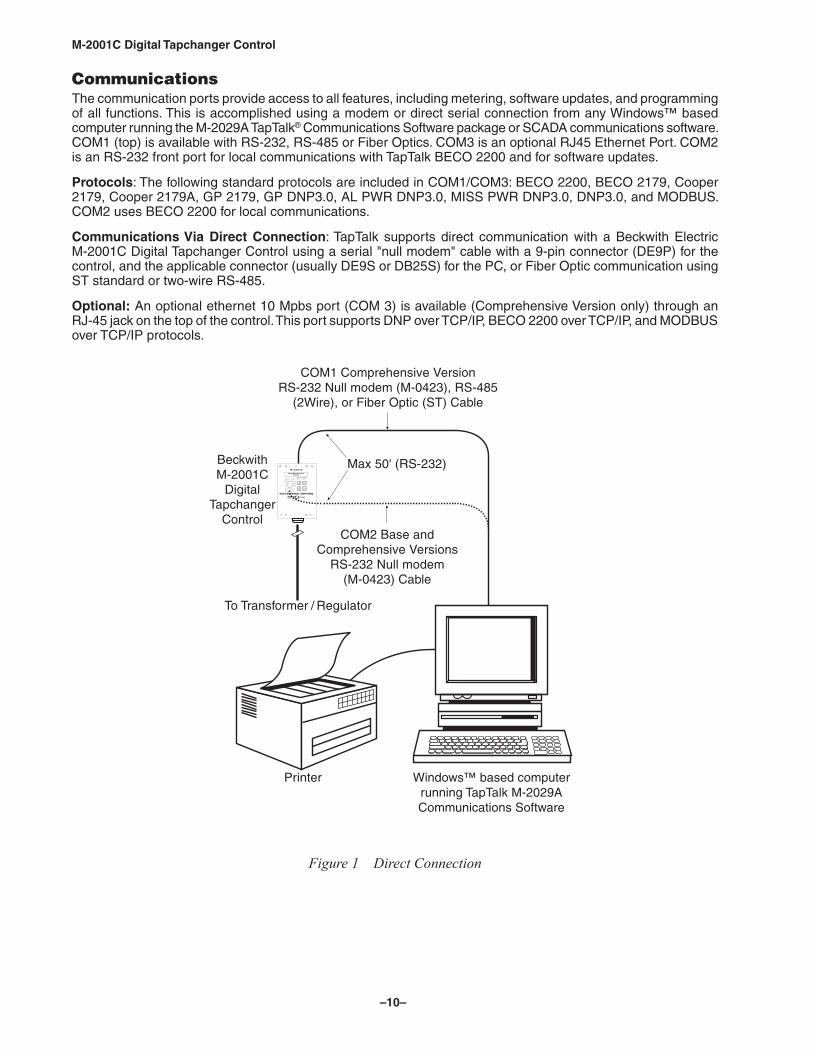
CommunicationsThe communication ports provide access to all features, including metering, software updates, and programming of all functions. This is accomplished using a modem or direct serial connection from any Windows™ based computer running the M-2029A TapTalk® Communications Software package or SCADA communications software. COM1 (top) is available with RS-232, RS-485 or Fiber Optics. COM3 is an optional RJ45 Ethernet Port. COM2 is an RS-232 front port for local communications with TapTalk BECO 2200 and for software updates.
Protocols: The following standard protocols are included in COM1/COM3: BECO 2200, BECO 2179, Cooper 2179, Cooper 2179A, GP 2179, GP DNP3.0, AL PWR DNP3.0, MISS PWR DNP3.0, DNP3.0, and MODBUS. COM2 uses BECO 2200 for local communications.
Communications Via Direct Connection: TapTalk supports direct communication with a Beckwith Electric M-2001C Digital Tapchanger Control using a serial "null modem" cable with a 9-pin connector (DE9P) for the control, and the applicable connector (usually DE9S or DB25S) for the PC, or Fiber Optic communication using ST standard or two-wire RS-485.
Optional: An optional ethernet 10 Mpbs port (COM 3) is available (Comprehensive Version only) through an RJ-45 jack on the top of the control. This port supports DNP over TCP/IP, BECO 2200 over TCP/IP, and MODBUS over TCP/IP protocols.
Windows™ based computerrunning TapTalk M-2029ACommunications Software
Figure 1 Direct Connection
–11–
M‑2001C Digital Tapchanger Control
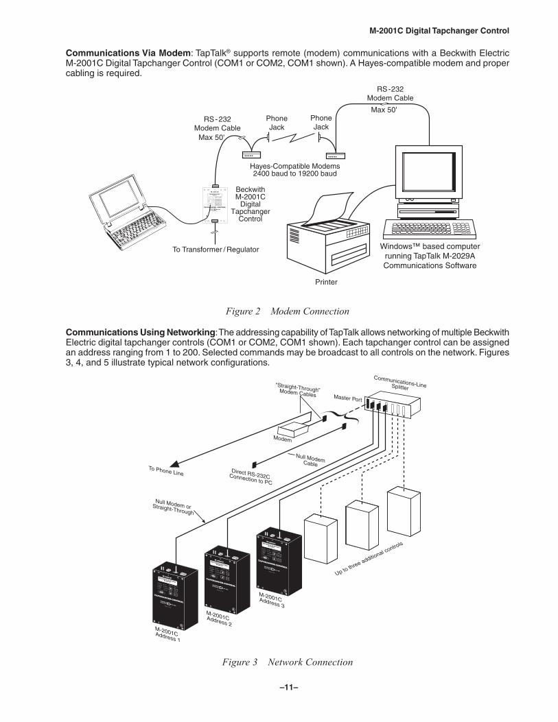
Communications Via Modem: TapTalk® supports remote (modem) communications with a Beckwith Electric M-2001C Digital Tapchanger Control (COM1 or COM2, COM1 shown). A Hayes-compatible modem and proper cabling is required.
Windows™ based computerrunning TapTalk M-2029ACommunications Software
Figure 2 Modem Connection
Communications Using Networking: The addressing capability of TapTalk allows networking of multiple Beckwith Electric digital tapchanger controls (COM1 or COM2, COM1 shown). Each tapchanger control can be assigned an address ranging from 1 to 200. Selected commands may be broadcast to all controls on the network. Figures 3, 4, and 5 illustrate typical network configurations.
Figure 3 Network Connection
–12–
M‑2001C Digital Tapchanger Control
Windows™ based computerrunning TapTalk M-2029ACommunications Software
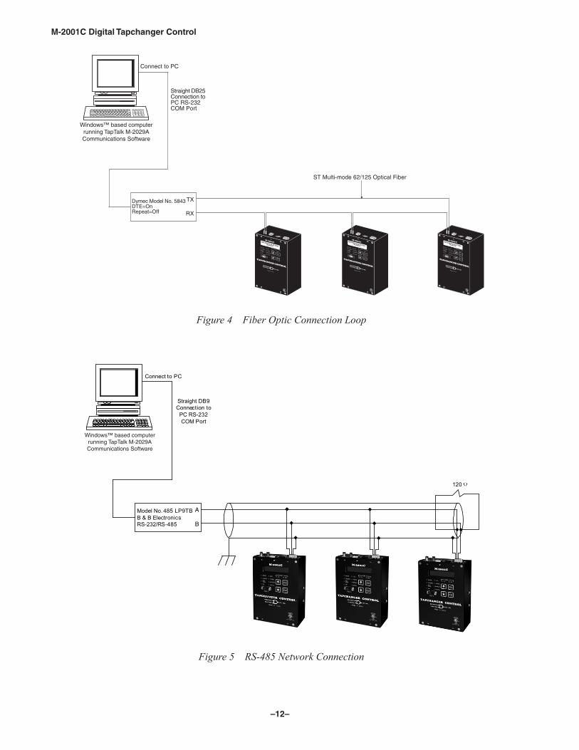
Figure 4 Fiber Optic Connection Loop
A
B
Straight DB9Connection to
PC RS-232COM Port
Connect to PC
Model No. 485 LP9TBB & B ElectronicsRS-232/RS-485
120
Windows™ based computerrunning TapTalk M-2029ACommunications Software
Figure 5 RS‑485 Network Connection
–13–
M‑2001C Digital Tapchanger Control
Application: Using a PC, the operator has real-time, remote access to all functions of the M-2001C Digital Tapchanger Control. The control can act as the monitoring point for all voltage, current, and related power quantities, thereby simplifying operation while avoiding transducers and multiple Remote Terminal Unit (RTU) analog inputs. The protocols implement half-duplex, two-way communications. This allows all functions, which would otherwise require the presence of an operator at the control, to be performed remotely. Communication capabilities include: • Interrogation and modification of setpoints
• Broadcast of commands, such as tap change inhibit and voltage reduction (up to three steps) to networked controls
• Recognition of alarm conditions, such as voltage extremes and excessive load
• Selective control of raise and lower tap change operations
• Re-configuration of the control, such as a change to the demand integration time period or a selection of different alarm parameters
Unit Identifier: A 2-row by 15-character alphanumeric sequence, set by the user, can be used for unit identification.
–14–
M‑2001C Digital Tapchanger Control
Tests and StandardsM-2001C Digital Tapchanger Control complies with the following type tests and standards:
Voltage Withstand
Dielectric WithstandIEC 60255-5 1,500 Vac for 1 minute applied to each independent circuit to earth 1,500 Vac for 1 minute applied between each independent circuit
Impulse VoltageIEC 60255-5 5,000 V pk, +/- polarity applied to each independent circuit to earth 5,000 V pk, +/- polarity applied between each independent circuit 1.2 by 50 µs, 500 ohms impedance, three surges at 1 every 5 seconds
IEC 60255-5 > 100 Megaohms
Electrical Environment
Electrostatic Discharge TestIEC 60255-22-2 Class 4 (8 kV) – point contact discharge
IEC 60255-22-2 Class 4 (15 kV) – air discharge
Fast Transient Disturbance TestIEC 60255-22-4 Class A (4 kV, 2.5 kHz)
Surge Withstand CapabilityANSI/IEEE 2,500 V pk-pk oscillatory applied to each independent circuit to earthC37.90.1- 2,500 V pk-pk oscillatory applied between each independent circuit1989 5,000 V pk Fast Transient applied to each independent circuit to earth 5,000 V pk Fast Transient applied between each independent circuit
ANSI/IEEE 2,500 V pk-pk oscillatory applied to each independent circuit to earthC37.90.1- 2,500 V pk-pk oscillatory applied between each independent circuit2002 4,000 V pk Fast Transient burst applied to each independent circuit to earth 4,000 V pk Fast Transient burst applied between each independent circuit
NOTE: The signal is applied to the digital data circuits (RS-232, RS-485, Ethernet communication port coupling port) through capacitive coupling clamp.
Surge ImmunityIEC 60255-22-5 2,000 V pk, ± polarity applied, 1.2 µs by 50 µs, five surges, 1 every 5 seconds
Radiated Electromagnetic Withstand CapabilityAll units protected against electromagnetic radiated interference from portable communications transceivers
Atmospheric Environment
Temperature: Control operates from -40° C to +85° C with either the LCD or Vacuum Fluorescent Display NOTE: The LCD display's functional temperature range is -20° C to +70° C. The optional vacuum fluorescent
display's functional temperature range is -40° C to +80° C.
IEC 60068-2-1 Cold, -40° C IEC 60068-2-2 Dry Heat, +80° CIEC 60068-2-78 Damp Heat, +40° C @ 93% RH
IEC 60068-2-30 Damp Heat Condensation Cycle, 25° C, +40° C @ 95% RH
–15–
M‑2001C Digital Tapchanger Control
Mechanical Environment
VibrationIEC 60255-21-1 Vibration response Class 1, 0.5 g Vibration endurance Class 1, 1.0 g
CompliancecULus-Listed per 508 – Industrial Control Equipment
– Industrial Control Equipment Certified for Canada CAN/CSA C22.2 No. 14-M91
cULus-Listed Component per 508A Table SA1.1 Industrial Control Panels
Recommended Storage Parameters
Temperature: 5° C to 40° C
Humidity: Maximum relative humidity 80% for temperatures up to 31° C, decreasing to 31° C linearly to 50% relative humidity at 40° C.
Environment: Storage area to be free of dust, corrosive gases, flammable materials, dew, percolating water, rain and solar radiation.
Periodic Surveillance During Storage: The M-2001C contains electrolytic capacitors. It is recommended that power be applied to the control every three to five years for a period not less than one hour to help prevent the electrolytic capacitors from drying out.
Physical(M-2001C Comprehensive, BASE-T, BASE-RS, BASE-R)
Size: 5 13/16" wide x 8 1/2" high x 3" deep (10.81 cm x 21.6 cm x 7.62 cm)
Mounting: Unit mounts directly to adapter or conversion front panels sized to replace popular industry tapchanger controls.
Approximate Weight: 3 lbs, 11 oz (1.67 kg)
Approximate Shipping Weight: 6 lbs, 11 oz (3.03 kg)
Patent & WarrantyThe M-2001C Tapchanger Control is covered by U.S. Patents 5,315,527 and 5,581,173.
The M-2001C Tapchanger Control, M-2026 AC-DC Control Power Backup Supply and M-2027 Control Power Backup Supply-AC Only, M-2948 Tap Position Sensor, and M-2025B(D) Current Loop Interface Modules are covered by a five-year warranty from date of shipment.
Specification subject to change without notice.
–16–
M‑2001C Digital Tapchanger Control
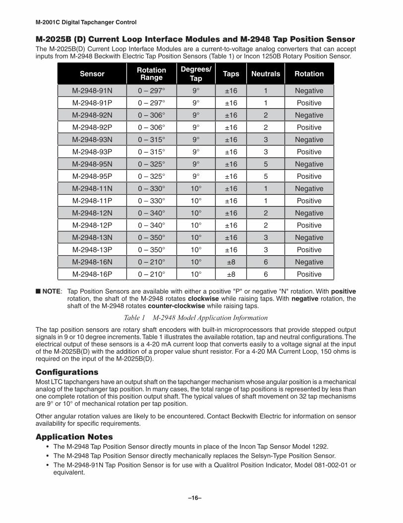
M-2025B (D) Current Loop Interface Modules and M-2948 Tap Position SensorThe M-2025B(D) Current Loop Interface Modules are a current-to-voltage analog converters that can accept inputs from M-2948 Beckwith Electric Tap Position Sensors (Table 1) or Incon 1250B Rotary Position Sensor.
Sensor Rotation Range
Degrees/Tap
Taps Neutrals Rotation
M-2948-91N 0 – 297° 9° ±16 1 Negative
M-2948-91P 0 – 297° 9° ±16 1 Positive
M-2948-92N 0 – 306° 9° ±16 2 Negative
M-2948-92P 0 – 306° 9° ±16 2 Positive
M-2948-93N 0 – 315° 9° ±16 3 Negative
M-2948-93P 0 – 315° 9° ±16 3 Positive
M-2948-95N 0 – 325° 9° ±16 5 Negative
M-2948-95P 0 – 325° 9° ±16 5 Positive
M-2948-11N 0 – 330° 10° ±16 1 Negative
M-2948-11P 0 – 330° 10° ±16 1 Positive
M-2948-12N 0 – 340° 10° ±16 2 Negative
M-2948-12P 0 – 340° 10° ±16 2 Positive
M-2948-13N 0 – 350° 10° ±16 3 Negative
M-2948-13P 0 – 350° 10° ±16 3 Positive
M-2948-16N 0 – 210° 10° ±8 6 Negative
M-2948-16P 0 – 210° 10° ±8 6 Positive
NOTE: Tap Position Sensors are available with either a positive "P" or negative "N" rotation. With positive rotation, the shaft of the M-2948 rotates clockwise while raising taps. With negative rotation, the shaft of the M-2948 rotates counter-clockwise while raising taps.
Table 1 M‑2948 Model Application InformationThe tap position sensors are rotary shaft encoders with built-in microprocessors that provide stepped output signals in 9 or 10 degree increments. Table 1 illustrates the available rotation, tap and neutral configurations. The electrical output of these sensors is a 4-20 mA current loop that converts easily to a voltage signal at the input of the M-2025B(D) with the addition of a proper value shunt resistor. For a 4-20 MA Current Loop, 150 ohms is required on the input of the M-2025B(D).
ConfigurationsMost LTC tapchangers have an output shaft on the tapchanger mechanism whose angular position is a mechanical analog of the tapchanger tap position. In many cases, the total range of tap positions is represented by less than one complete rotation of this position output shaft. The typical values of shaft movement on 32 tap mechanisms are 9° or 10° of mechanical rotation per tap position.
Other angular rotation values are likely to be encountered. Contact Beckwith Electric for information on sensor availability for specific requirements.
Application Notes • The M-2948 Tap Position Sensor directly mounts in place of the Incon Tap Sensor Model 1292. • The M-2948 Tap Position Sensor directly mechanically replaces the Selsyn-Type Position Sensor. • The M-2948-91N Tap Position Sensor is for use with a Qualitrol Position Indicator, Model 081-002-01 or
equivalent.
–17–
M‑2001C Digital Tapchanger Control
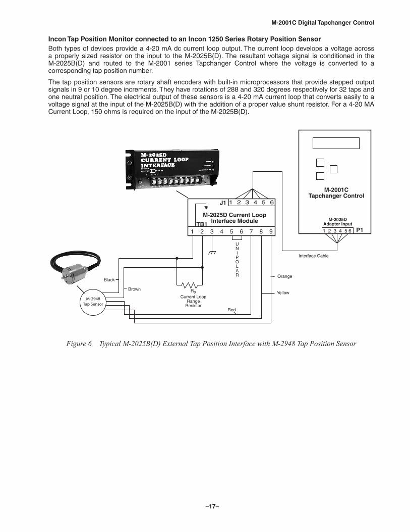
Incon Tap Position Monitor connected to an Incon 1250 Series Rotary Position SensorBoth types of devices provide a 4-20 mA dc current loop output. The current loop develops a voltage across a properly sized resistor on the input to the M-2025B(D). The resultant voltage signal is conditioned in the M-2025B(D) and routed to the M-2001 series Tapchanger Control where the voltage is converted to a corresponding tap position number.
The tap position sensors are rotary shaft encoders with built-in microprocessors that provide stepped output signals in 9 or 10 degree increments. They have rotations of 288 and 320 degrees respectively for 32 taps and one neutral position. The electrical output of these sensors is a 4-20 mA current loop that converts easily to a voltage signal at the input of the M-2025B(D) with the addition of a proper value shunt resistor. For a 4-20 MA Current Loop, 150 ohms is required on the input of the M-2025B(D).
M-2948Tap Sensor
Figure 6 Typical M‑2025B(D) External Tap Position Interface with M‑2948 Tap Position Sensor
–18–
M‑2001C Digital Tapchanger Control
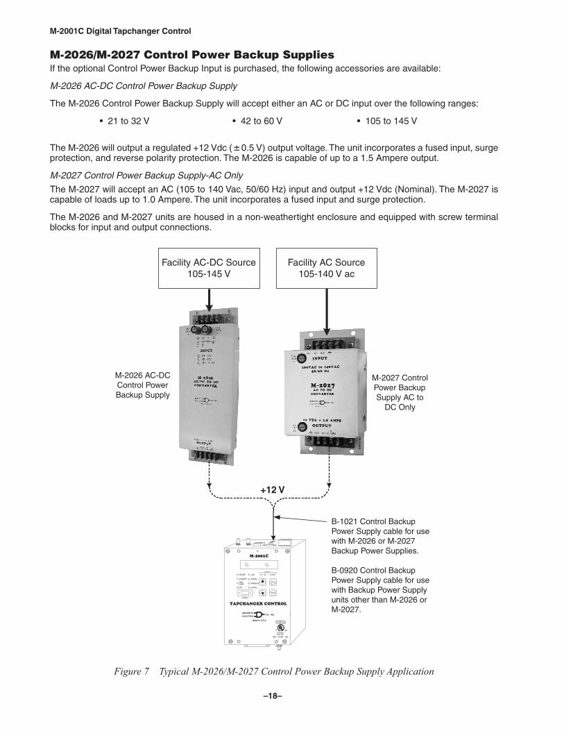
M-2026/M-2027 Control Power Backup SuppliesIf the optional Control Power Backup Input is purchased, the following accessories are available:
M‑2026 AC‑DC Control Power Backup Supply
The M-2026 Control Power Backup Supply will accept either an AC or DC input over the following ranges:
• 21 to 32 V • 42 to 60 V • 105 to 145 V
The M-2026 will output a regulated +12 Vdc (0.5 V) output voltage. The unit incorporates a fused input, surge protection, and reverse polarity protection. The M-2026 is capable of up to a 1.5 Ampere output.
M‑2027 Control Power Backup Supply‑AC Only
The M-2027 will accept an AC (105 to 140 Vac, 50/60 Hz) input and output +12 Vdc (Nominal). The M-2027 is capable of loads up to 1.0 Ampere. The unit incorporates a fused input and surge protection.
The M-2026 and M-2027 units are housed in a non-weathertight enclosure and equipped with screw terminal blocks for input and output connections.
COM 2
IND. CONT. EQ.
Made in U.S.A.
.CNI.OCHTI
CIRTCELE
WKCEB
R
PURPOSEGENERAL
W
WREP
LO
VR
RE
RA SI E
KO
V/RED
MANUAL
LDC
LOCAL
COM 1TX RX
Exit
Ent
4 F 6 4LISTED
C US
Facility AC-DC Source105-145 V
Facility AC Source105-140 V ac
+12 V
M-2026 AC-DCControl PowerBackup Supply
M-2027 ControlPower BackupSupply AC to
DC Only
B-1021 Control BackupPower Supply cable for usewith M-2026 or M-2027Backup Power Supplies.
B-0920 Control BackupPower Supply cable for usewith Backup Power Supplyunits other than M-2026 orM-2027.
Figure 7 Typical M‑2026/M‑2027 Control Power Backup Supply Application
–19–
M‑2001C Digital Tapchanger Control
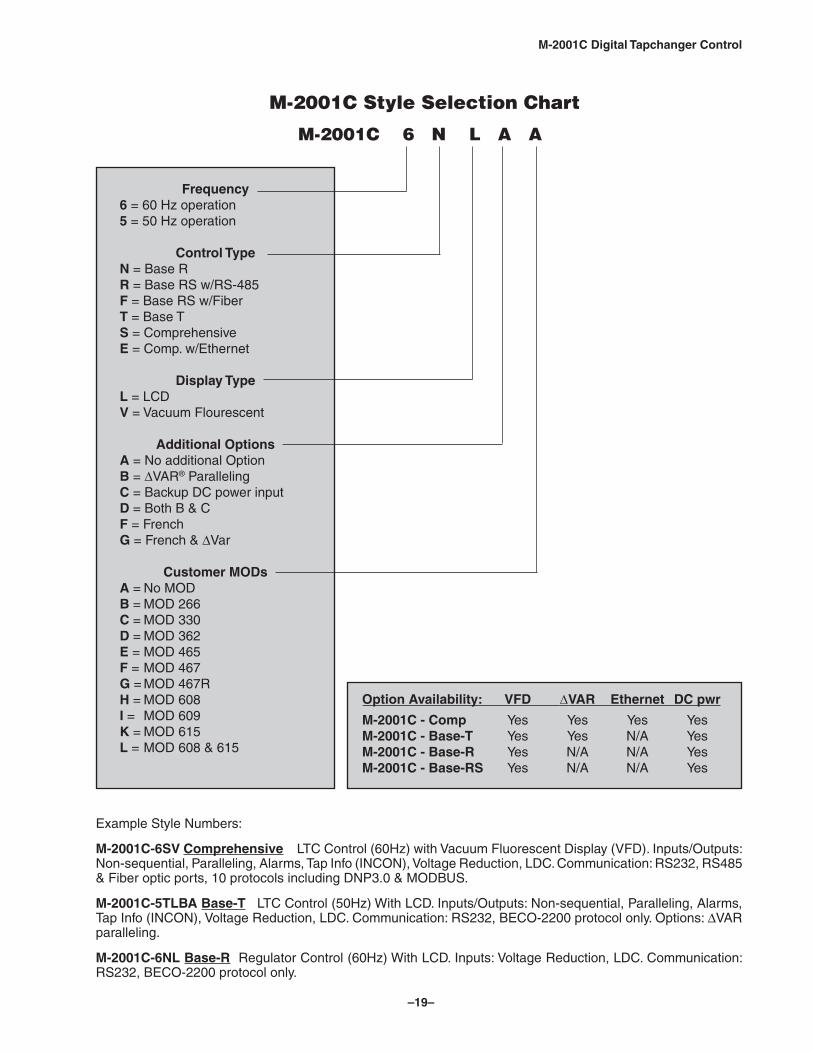
Example Style Numbers:
M-2001C-6SV Comprehensive LTC Control (60Hz) with Vacuum Fluorescent Display (VFD). Inputs/Outputs: Non-sequential, Paralleling, Alarms, Tap Info (INCON), Voltage Reduction, LDC. Communication: RS232, RS485 & Fiber optic ports, 10 protocols including DNP3.0 & MODBUS.
M-2001C-5TLBA Base-T LTC Control (50Hz) With LCD. Inputs/Outputs: Non-sequential, Paralleling, Alarms, Tap Info (INCON), Voltage Reduction, LDC. Communication: RS232, BECO-2200 protocol only. Options: ∆VAR paralleling.
M-2001C-6NL Base-R Regulator Control (60Hz) With LCD. Inputs: Voltage Reduction, LDC. Communication: RS232, BECO-2200 protocol only.
M-2001C Style Selection Chart
M-2001C 6 N L A A
Frequency6 = 60 Hz operation5 = 50 Hz operation
Control TypeN = Base RR = Base RS w/RS-485F = Base RS w/FiberT = Base TS = ComprehensiveE = Comp. w/Ethernet
Display TypeL = LCDV = Vacuum Flourescent
Additional OptionsA = No additional OptionB = ∆VAR® ParallelingC = Backup DC power inputD = Both B & CF = FrenchG = French & ∆Var
Customer MODsA = No MODB = MOD 266C = MOD 330D = MOD 362E = MOD 465F = MOD 467G = MOD 467RH = MOD 608I = MOD 609K = MOD 615L = MOD 608 & 615
Option Availability: VFD DVAR Ethernet DC pwr
M-2001C - Comp Yes Yes Yes YesM-2001C - Base-T Yes Yes N/A YesM-2001C - Base-R Yes N/A N/A YesM-2001C - Base-RS Yes N/A N/A Yes

BECKWITH ELECTRIC CO., INC.6190 - 118th Avenue North • Largo, Florida 33773-3724 U.S.A.
PHONE (727) 544-2326 • FAX (727) [email protected]
www.beckwithelectric.comISO 9001:2008
800-2001C-SP-09MC2 06/17© 2003 Beckwith Electric Co. All Rights Reserved.Printed in U.S.A. (09.24.02)