Embed Size (px)
Citation preview
1
NYSEARCH
Direct AssessmentActivities by NYSEARCH/NGA & NGA
Daphne D’Zurko, NYSEARCH/NGADOT R & D ForumMarch 2005
2
NYSEARCH/NGA Initiatives for Direct Assessment (DA)♦ Phase 1 ECDA Validation Project
– March 2002 – April 2003
♦ Phase 2 DA Project– April 2003 – September 2004
♦ ECDA Criteria Project– June 2004 – mid-2006
♦ RFP related to Difficult Applications of DA– Projects initiated December 2004
♦ NGA activity related to evolving Industry Standards
3
Phase I and Phase II Participants
♦ Nine NYS LDC NGA members participated in Ph I DA Validation Project:– KeySpan Central Hudson– National Fuel St. Lawrence Gas– NYS Electric & Gas Consolidated Edison– Niagara Mohawk Orange & Rockland– Rochester Gas & Electric
♦ Twelve LDCs participating in Ph II DA Project:– KeySpan Central Hudson– National Fuel Enbridge/St. Lawrence Gas– NYS Electric & Gas Consolidated Edison– Niagara Mohawk Orange & Rockland– Rochester Gas & Electric PECO– Questar Public Service Electric & Gas
♦ NY PSC involved from start as active participant
4
Phase I NYS DA Process Validation Project Objectives♦Demonstrate that ECDA is a valid
alternative to ILI and pressure testing♦Prove to NGA-NY members, NYS PSC
Staff, and federal regulators that ECDA can be used to assess pipeline integrity with respect to external corrosion, coating flaws and third party damage
♦Fill an industry gap for quantitative validation
5
Key Project Elements
♦Consistent with RP0502♦Process applied in a consistent and
structured manner across NYS allowing pooling of data
♦ Industry expert, CC Technologies –objective third party
6
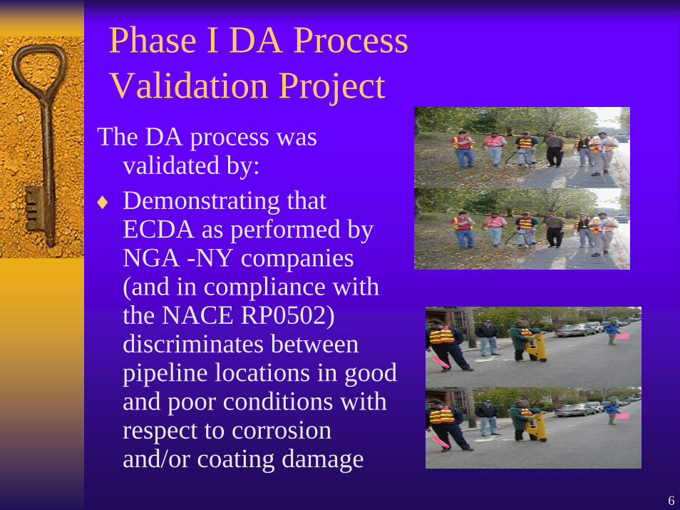
Phase I DA Process Validation Project
The DA process was validated by:
♦ Demonstrating that ECDA as performed by NGA -NY companies (and in compliance with the NACE RP0502) discriminates between pipeline locations in good and poor conditions with respect to corrosion and/or coating damage
7
Phase I Technical Approach♦ Nine NGA members performed ECDA on ~ 2
mile segments (total 20 miles)
♦ Utilized indirect survey tools and selected locations on the pipe predicted to have indications and predicted to have non-indications (controls).
♦ Excavate ECDA indications and controls and assess condition using 3 separate metrics
1. Coating damage2. Corrosion damage (i.e., metal loss)3. Corrosivity (e.g., soil chemistry at pipe surface)
♦ Compare predictions to actual results♦ Perform statistical analysis
8
Phase II Technical Approach• Phase II included adding to Phase I validation
(total ~60 miles)
• Redo analysis to decrease statisticaluncertainties
• Interpretation of probabilities require consideration of confidence intervals
• Develop understanding and approach for addressing challenging or difficult environments with DA
9
Project Definitions♦ Indications: Locations on pipe predicted to have
anomalies. (Anomalies=coating flaws, external corrosion, metal loss, third party damage)
♦ Controls (non-indications): Locations on pipe predicted to be in good condition.
Indications and controls selected based on survey data, pre-assessment information and operator knowledge of system
Controls required to conduct statistical analysis
10
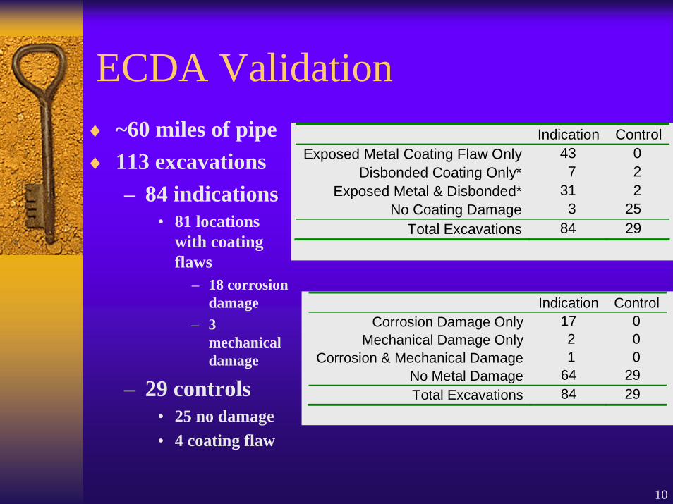
ECDA Validation♦ ~60 miles of pipe♦ 113 excavations
– 84 indications • 81 locations
with coating flaws
– 18 corrosion damage
– 3 mechanical damage
– 29 controls• 25 no damage• 4 coating flaw
Indication Control Exposed Metal Coating Flaw Only 43 0
Disbonded Coating Only* 7 2 Exposed Metal & Disbonded* 31 2
No Coating Damage 3 25 Total Excavations 84 29
Indication Control Corrosion Damage Only 17 0
Mechanical Damage Only 2 0 Corrosion & Mechanical Damage 1 0
No Metal Damage 64 29 Total Excavations 84 29
11
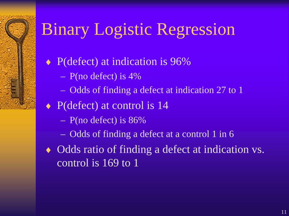
Binary Logistic Regression
♦ P(defect) at indication is 96%– P(no defect) is 4%– Odds of finding a defect at indication 27 to 1
♦ P(defect) at control is 14– P(no defect) is 86%– Odds of finding a defect at a control 1 in 6
♦ Odds ratio of finding a defect at indication vs. control is 169 to 1
12
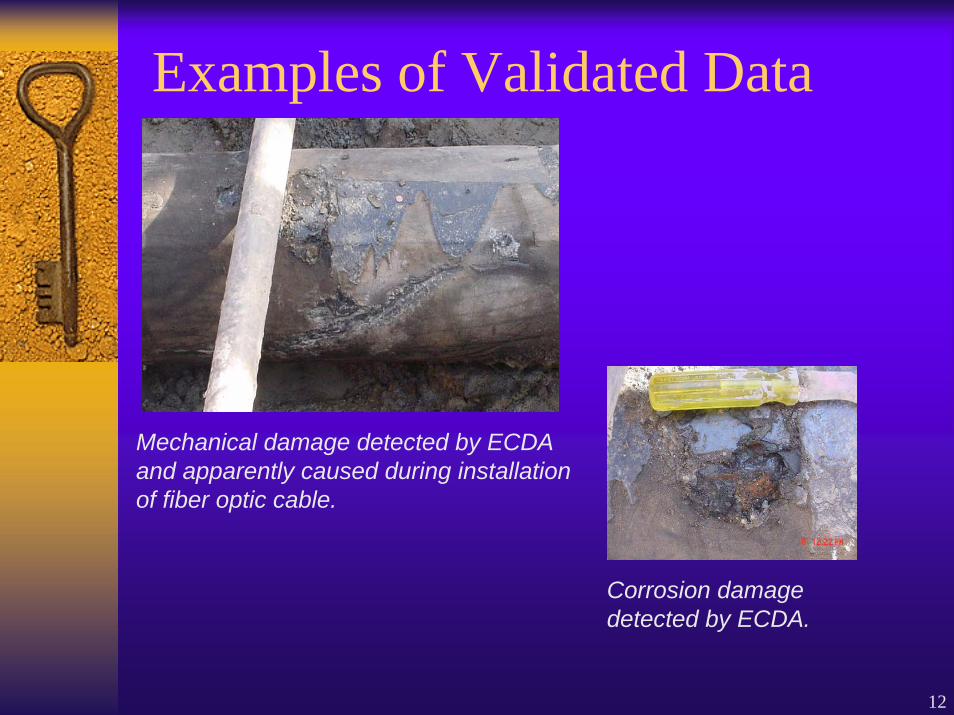
Examples of Validated Data
Mechanical damage detected by ECDA and apparently caused during installation of fiber optic cable.
Corrosion damage detected by ECDA.
13
Phase I Conclusions
♦ Data collected supports ECDA as a valid integrity management tool
♦ ECDA on par with ILI and pressure testing
♦ Improved technical capability by member companies to perform DA
♦ Elevated NYS PSC understanding of DA
14
Lessons Learned about DA Implementation Overall:♦ DA requires a high
attention to detail
♦ DA requires a thorough engineering analysis and approach
♦ Communication essential!
15
Additional Activities in Phase II♦ Develop consistent DA approaches
and protocols for “special areas”– Cased pipe– Bare pipe– Inaccessible pipe– Stray current areas
♦ Test new long range guided wave inspection tools
♦ Develop DA Plans for NGA Integrity Management Program
16
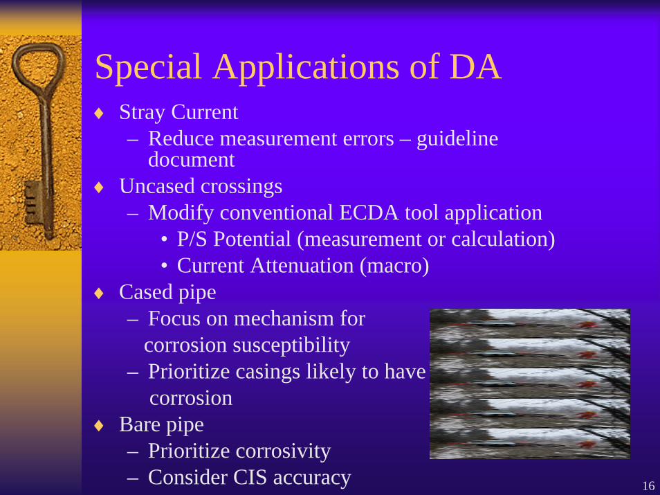
Special Applications of DA♦ Stray Current
– Reduce measurement errors – guideline document
♦ Uncased crossings– Modify conventional ECDA tool application
• P/S Potential (measurement or calculation)• Current Attenuation (macro)
♦ Cased pipe– Focus on mechanism for
corrosion susceptibility– Prioritize casings likely to have
corrosion♦ Bare pipe
– Prioritize corrosivity– Consider CIS accuracy
17
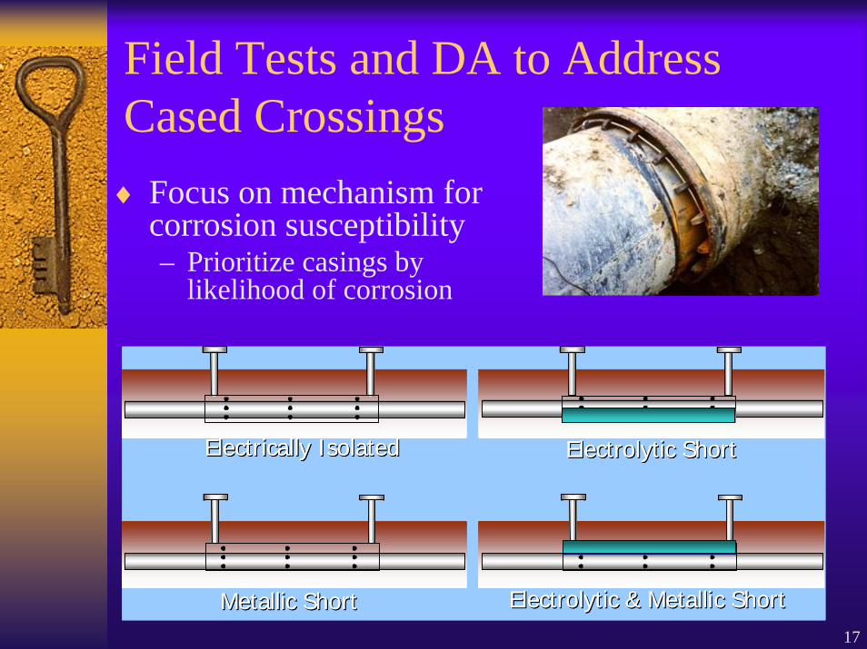
Field Tests and DA to Address Cased Crossings♦ Focus on mechanism for
corrosion susceptibility– Prioritize casings by
likelihood of corrosion
Electrically IsolatedElectrically Isolated Electrolytic ShortElectrolytic Short
Metallic ShortMetallic Short Electrolytic & Metallic ShortElectrolytic & Metallic Short
Electrically IsolatedElectrically Isolated Electrolytic ShortElectrolytic Short
Metallic ShortMetallic Short Electrolytic & Metallic ShortElectrolytic & Metallic Short
18
DA to Address Bare Pipe
♦Coating flaw tools not relevant♦Potential measurement more accurate♦Other prioritization tools for
corrosivity– Soil Properties (e.g., resistivity)
19
NGA Work to Finalize DA Plans♦ Multiple constraints
– Detailed specificity (including criteria)– Operator flexibility (for customizing)– Technical accuracy
♦ Plans for insertion to IMP*– ECDA– ICDA– SCCDA
*Overall plan developed by Gulf Interstate for NGA
20
Phase II Conclusions♦ Validation further improved♦ Protocols developed
– Inaccessible• Straightforward but
pipe-specific– Stray
• Issues known– Cased
• Approach good, direct examinations still issue– Bare
• Some success, more to do, work ongoing in industry♦ DA Plans developed
– Living documents
21
NYSEARCH/NGA ECDA Criteria Development Project
♦NYSEARCH/NGA teaming with CC Technologies & University of Florida
♦Main objective: Develop an Excel spreadsheet tool which aids the operator in selecting and prioritizing indications (and digs)
22
Selecting Direct ExaminationsHow does the operator select where to
excavate?♦ Survey data (Indirect Inspections)♦ Use of Preassessment data♦ Operator knowledge of the system♦ Expert opinion♦ Sound engineering judgment
SUBJECTIVE PROCESS
23
Selection of Digs
♦ Subjectivity used to consider site specific parameters and pipeline conditions influence selection
♦ Problem – Gas Rule requires uniform criteria for prioritization– Industry response is to use company specific numerical
criteria without consideration for pipeline conditions• Too many digs ($$$), or the wrong digs (safety)
♦ Solution – develop objective pipeline-specific criteria to work in conjunction with the process used today
24
Benefits of ECDA Criteria Model
In summary, criteria could help operators:
♦ Prioritize indications and determine where to dig as this process is often challenging
♦ Satisfy Pipeline Integrity Rule requirements
♦ Better defend dig locations (e.g., to regulators)
♦ Provide increased consistency among the NGA/NYSEARCH members
25
Examples of ECDA Criteria♦ CIS Criteria
– CP effectiveness criteria (i.e., -850mV or 100mV)?• What change is significant?• Is on/off relevant?• What is proper survey spacing?
♦ DCVG (or ACVG) Criteria– %IR and/or mV drop
• Depends on soil resistivity, pipe defect geometry/size, anode configuration, applied current
♦ Current Attenuation– % attenuation depends on resistivity, polarization
level/character, galvanic anodes, etc.
26
Need Criteria Specific to Pipeline Region
♦ Most tools relate above ground measurement of current or potential to coating or corrosion condition– Based on E and I distribution around pipeline
coating flaws and affected by• CP level, resistivity, coating condition (including
defect interaction), polarizability, galvanic anodes, depth of cover, Pipe OD.
♦ Use CP predictive models♦ A bonus: technical basis for survey spacing
27
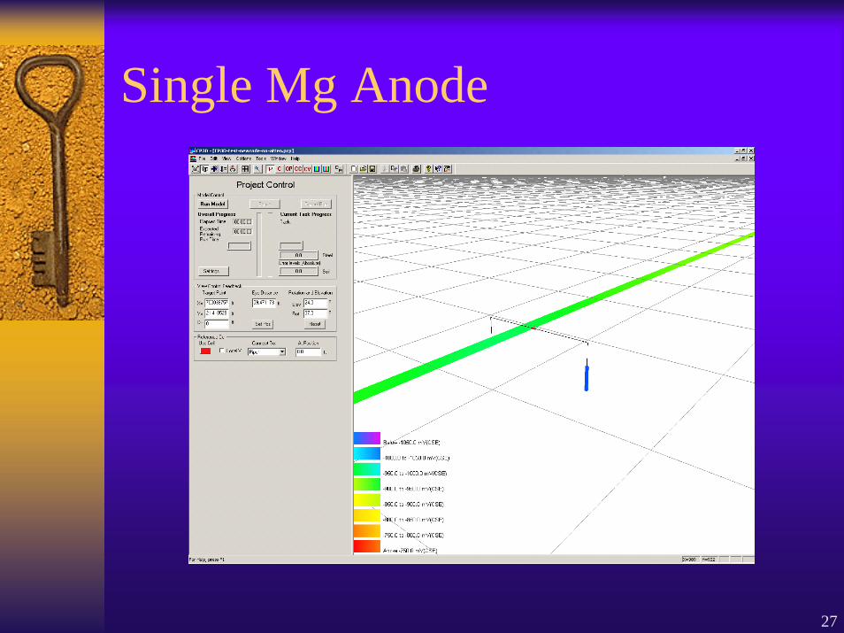
Single Mg Anode
28
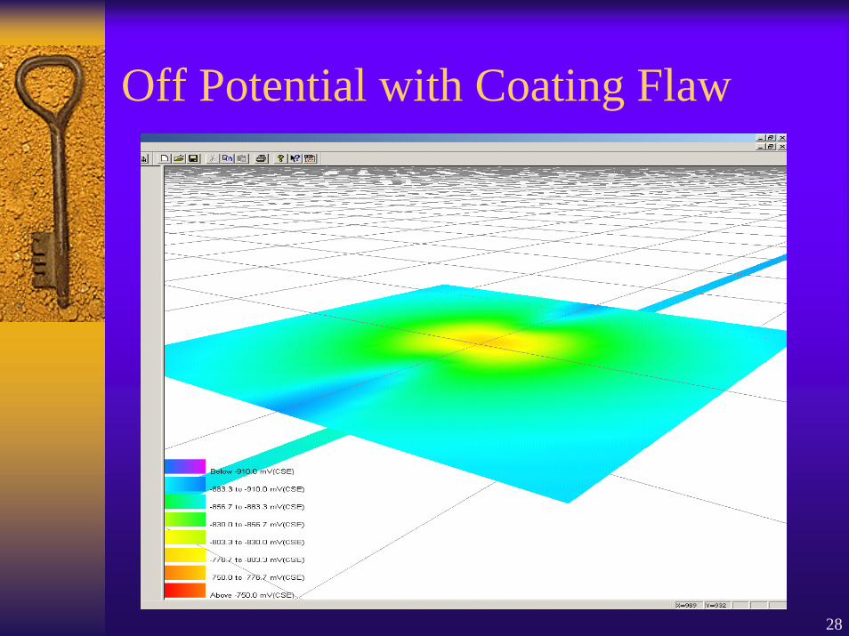
Off Potential with Coating Flaw
29
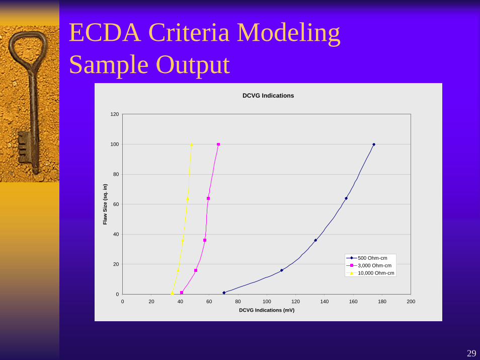
ECDA Criteria ModelingSample Output
DCVG Indications
0
20
40
60
80
100
120
0 20 40 60 80 100 120 140 160 180 200
DCVG Indications (mV)
Flaw
Siz
e (s
q. in
)
500 Ohm-cm3,000 Ohm-cm10,000 Ohm-cm
30
NYSEARCH/NGA Projects to Address Special Applications of DA♦ TWI/FBS Long Range Guided Ultrasonic
Inspection Technology♦ SwRI – Development of Long Term Monitor
Using MagnetoStrictive (MsS) Sensor♦ FINO AG – NoPig Inspection Technology♦ CCT – Enhanced Voltmeter to Address High
Impedance Areas
♦ Design, Installation and Operation of Utility-Specific Underground Test Bed (2005)– Testing funded and new approaches– Using for DA training and new technology evaluation
31
Current Thinking on Potential Gaps & Challenges
♦ Need to further develop quantitative bases for ECDA decisions
♦ Need to customize ECDA for specific pipeline regions
♦ Need to study root causes of corrosion♦ Need to improve interpretation of indirect
inspection survey data♦ Gaps exist for pieces of special ECDA areas:
station piping, multiple pipes in ROW, etc.
32
Overall Summary
♦ECDA process working well– Validated on pipes typical of most systems
♦Procedures are necessary for special applications within a segment
♦DA plans for IMPs are in place♦Custom ECDA criteria being developed♦Members stepping up activities on ICDA♦Technologies to address special applications
are being developed but gaps still exist