Embed Size (px)
Citation preview
sensors sensors Wegaufnehmer Wegaufnehmer Wegaufnehmer Wegaufnehmer Wegaufnehmer Wegaufnehmer WegaufWegaufnehmer Wegaufnehmer Wegaufnehmer Wegaufnehmer Wegaufnehmer We Wegaufnehmer Wegaufnehmer WegaufnehmeWegaufnehmer Wegaufnehmer Wegaufnehmer WegaufWegaufnehmer Wegaufnehmer Wegaufnehmer WegaufnehWegaufnehmer Wegaufnehmer
Wegaufnehmer Wegaufnehmer egaufnehmer Wegaufnehmer Wegaufnehmer Wegaufnehmeregaufnehmeregaufnehmer Wegaufnehmer Wegaufnehmer Wegaufnehmeregaufnehmer WegaufnehmerWegaufnehmer Wegaufnehmer Wegaufnehmer Wegaufnehmeegaufnehmeregaufnehmer Wegaufnehmer Wegaufnehmer Wegaufnehmegaufnehmer Wegaufnehmer
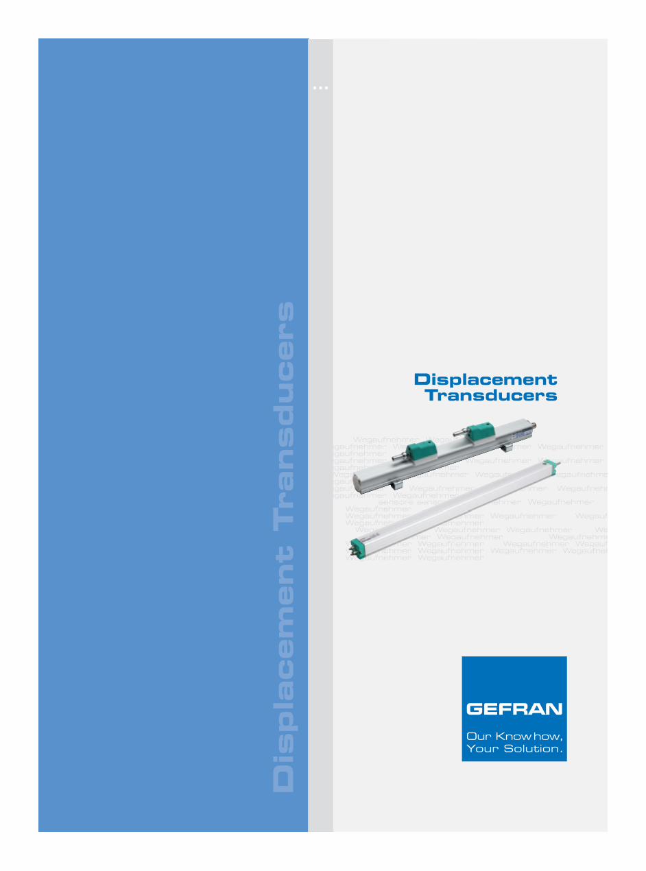
DisplacementTransducers
Dis
pla
cem
ent
Tra
nsducers
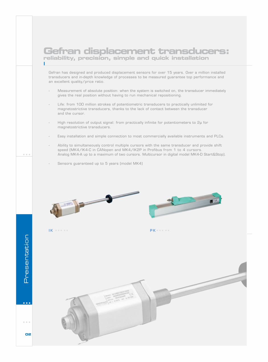
Gefran has designed and produced displacement sensors for over 15 years. Over a million installedtransducers and in-depth knowledge of processes to be measured guarantee top performance andan excellent quality/price ratio.
- Measurement of absolute position: when the system is switched on, the transducer immediatelygives the real position without having to run mechanical repositioning.
- Life: from 100 million strokes of potentiometric transducers to practically unlimited formagnetostrictive transducers, thanks to the lack of contact between the transducerand the cursor.
- High resolution of output signal: from practically infinite for potentiometers to 2µ formagnetostrictive transducers.
- Easy installation and simple connection to most commercially available instruments and PLCs.
- Ability to simultaneously control multiple cursors with the same transducer and provide shiftspeed (MK4/IK4-C in CANopen and MK4/IK2P in Profibus from 1 to 4 cursors.Analog MK4-A up to a maximum of two cursors. Multicursor in digital model MK4-D Start&Stop).
- Sensors guaranteed up to 5 years (model MK4)
Gefran displacement transducers:reliability, precision, simple and quick installation
I K P K
02
Presenta
tion
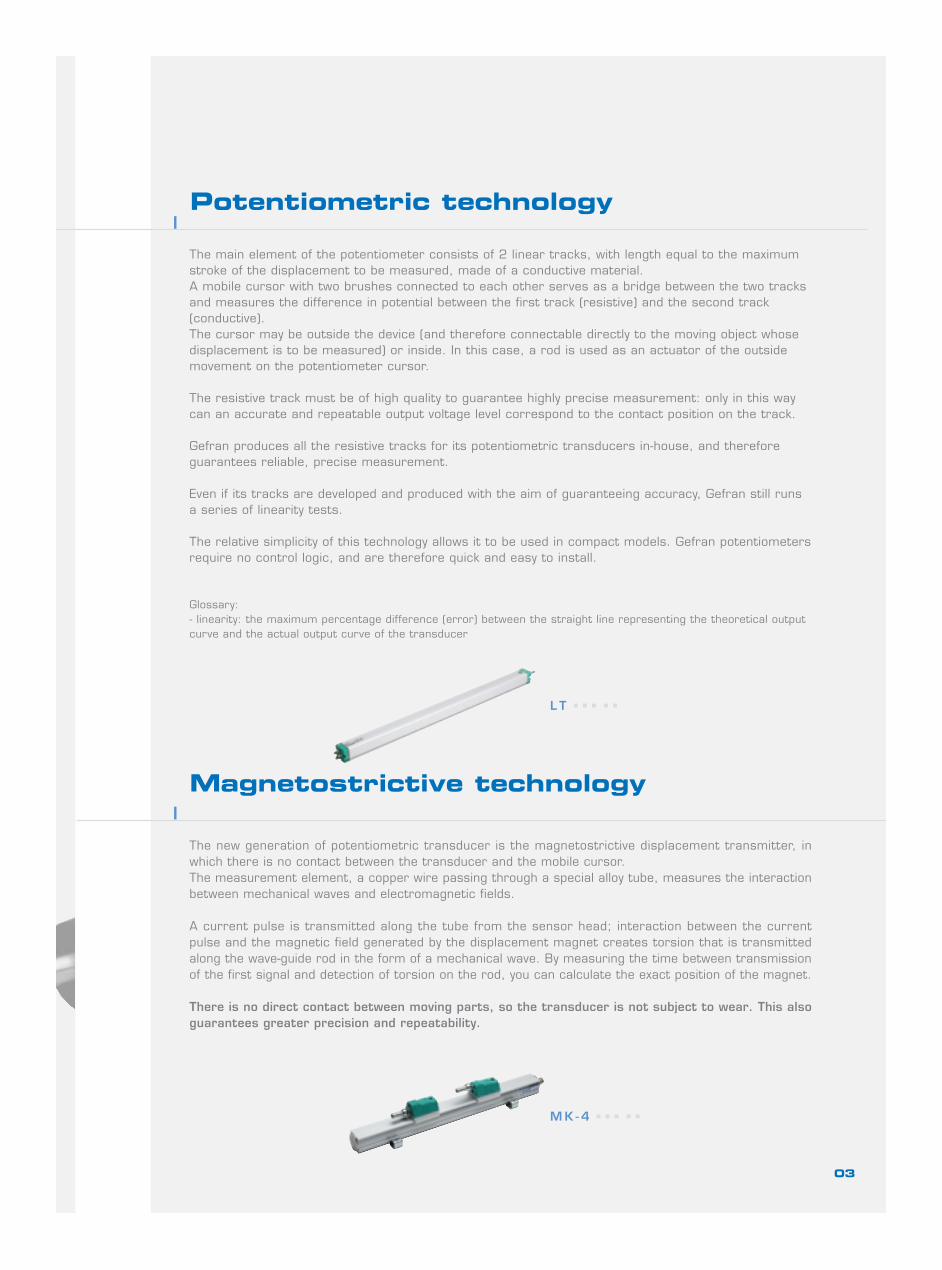
Potentiometric technology
The main element of the potentiometer consists of 2 linear tracks, with length equal to the maximumstroke of the displacement to be measured, made of a conductive material.A mobile cursor with two brushes connected to each other serves as a bridge between the two tracksand measures the difference in potential between the first track (resistive) and the second track(conductive).The cursor may be outside the device (and therefore connectable directly to the moving object whosedisplacement is to be measured) or inside. In this case, a rod is used as an actuator of the outsidemovement on the potentiometer cursor.
The resistive track must be of high quality to guarantee highly precise measurement: only in this waycan an accurate and repeatable output voltage level correspond to the contact position on the track.
Gefran produces all the resistive tracks for its potentiometric transducers in-house, and thereforeguarantees reliable, precise measurement.
Even if its tracks are developed and produced with the aim of guaranteeing accuracy, Gefran still runsa series of linearity tests.
The relative simplicity of this technology allows it to be used in compact models. Gefran potentiometersrequire no control logic, and are therefore quick and easy to install.
Glossary:- linearity: the maximum percentage difference (error) between the straight line representing the theoretical outputcurve and the actual output curve of the transducer
Magnetostrictive technology
The new generation of potentiometric transducer is the magnetostrictive displacement transmitter, inwhich there is no contact between the transducer and the mobile cursor.The measurement element, a copper wire passing through a special alloy tube, measures the interactionbetween mechanical waves and electromagnetic fields.
A current pulse is transmitted along the tube from the sensor head; interaction between the currentpulse and the magnetic field generated by the displacement magnet creates torsion that is transmittedalong the wave-guide rod in the form of a mechanical wave. By measuring the time between transmissionof the first signal and detection of torsion on the rod, you can calculate the exact position of the magnet.
There is no direct contact between moving parts, so the transducer is not subject to wear. This alsoguarantees greater precision and repeatability.
03
L T
M K - 4
GUIDE TO CHOOSING THEBEST TRANSDUCER
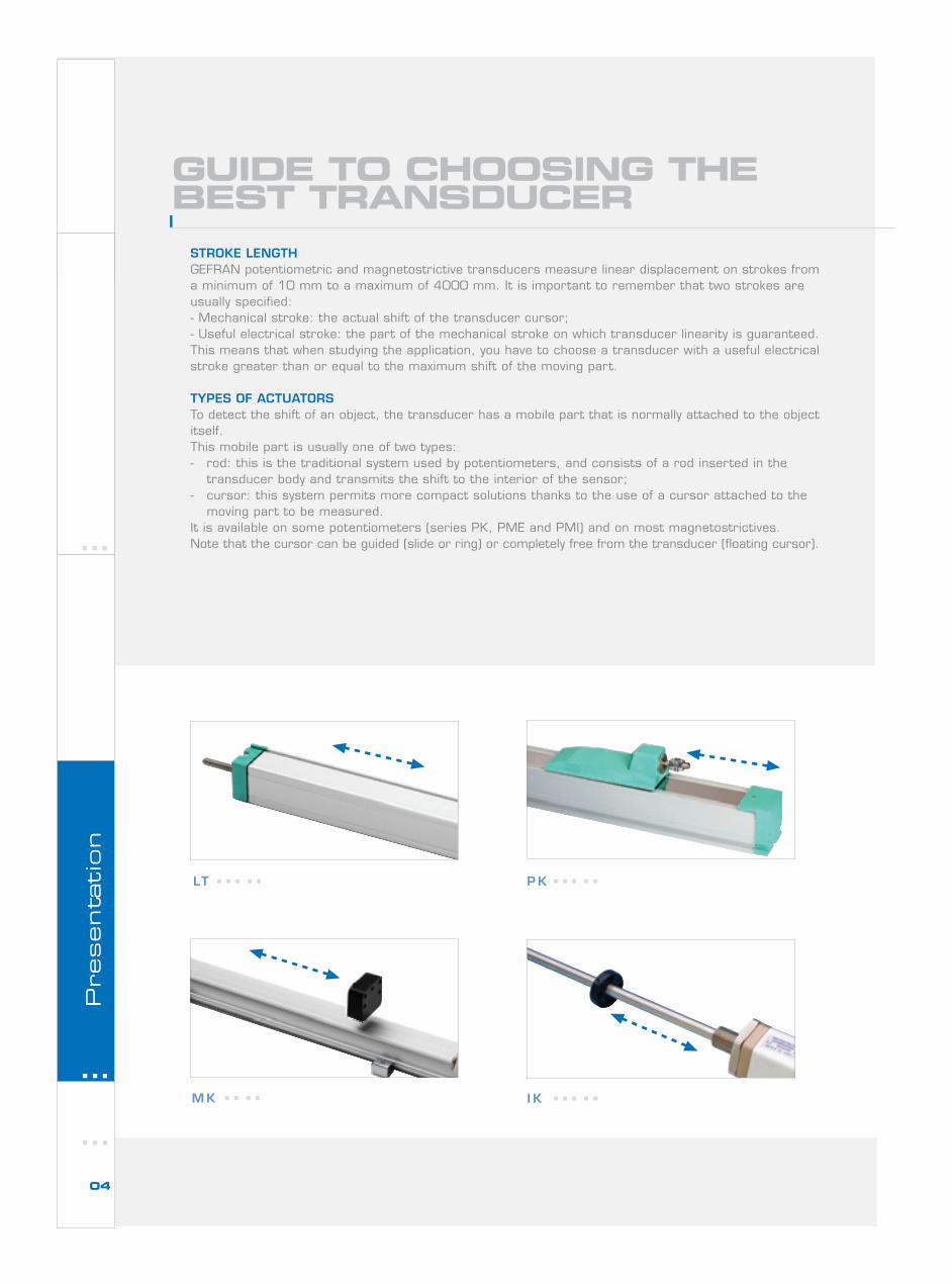
STROKE LENGTHGEFRAN potentiometric and magnetostrictive transducers measure linear displacement on strokes froma minimum of 10 mm to a maximum of 4000 mm. It is important to remember that two strokes areusually specified:- Mechanical stroke: the actual shift of the transducer cursor;- Useful electrical stroke: the part of the mechanical stroke on which transducer linearity is guaranteed.This means that when studying the application, you have to choose a transducer with a useful electricalstroke greater than or equal to the maximum shift of the moving part.
TYPES OF ACTUATORSTo detect the shift of an object, the transducer has a mobile part that is normally attached to the objectitself.This mobile part is usually one of two types:- rod: this is the traditional system used by potentiometers, and consists of a rod inserted in the
transducer body and transmits the shift to the interior of the sensor;- cursor: this system permits more compact solutions thanks to the use of a cursor attached to the
moving part to be measured.It is available on some potentiometers (series PK, PME and PMI) and on most magnetostrictives.Note that the cursor can be guided (slide or ring) or completely free from the transducer (floating cursor).
Presenta
tion
LT P K
M K I K
04
PROTECTION LEVELDepending on their structure and technology, GEFRAN linear displacement transducers guarantee differentlevels of protection against dust and liquids. You can choose within a range of IP40 to IP68, as shownon the following table:
COMMUNICATION INTERFACEPotentiometers supply a ratiometric output in voltage. This means that the output voltage range dependson the voltage use to feed the transducer.ATTENTION! The potentiometer must NOT be used as a variable resistance.If you want a 0..10 VDC or 4..20 mA conditioned signal as a potentiometer output, you can connect aPCIR conditioner to the device output.Magnetostrictive transducers let you choose the most appropriate output interface for the application:- analog output in voltage:0..5 VDC/5..0 VDC, 0..10 VDC/10..0 VDC, ± 5 VDC, ± 10 VDC- analog output in current:
0..20 mA, 4..20 mA- digital output:
start/stop (multicursor), PWM (monocursor)- SSI output:
16, 21, 24, 25 bit in binary or Gray code- CANopen output:
CiA DP 3.01 rel.4.0 and DS406- Profibus output:
DPV0 on RS485
PZ34-S PZ34-F PZ34-A
05
IP40 IP60 IP65 IP67 IP68
PS
PMAPY3
PMEPY2
IK1-IK2-IK4PY1 PZ34 PR65
MK4PA1 PZ12 PC PMI
PK LT LT RK - RKA - RKC IC
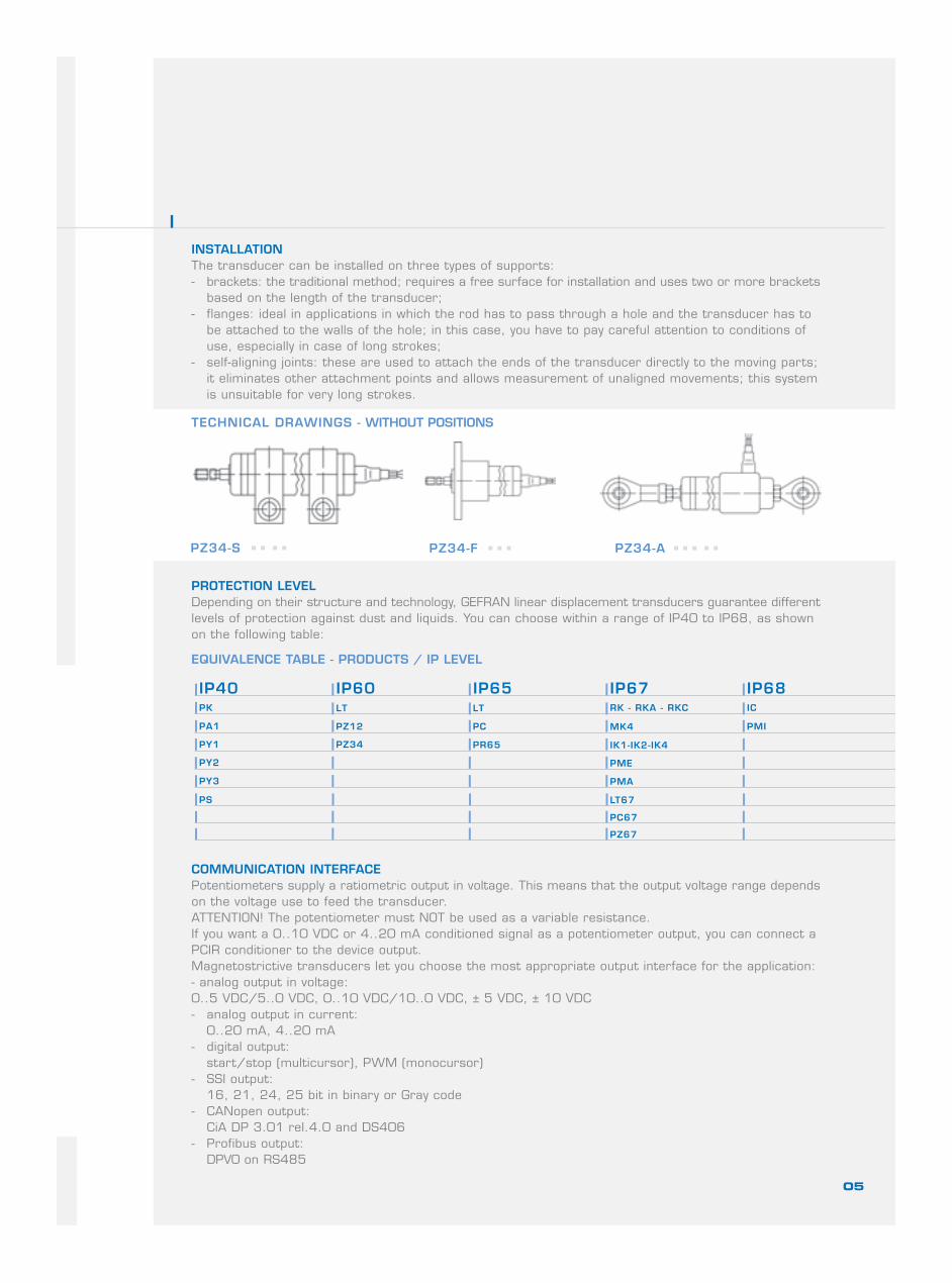
INSTALLATIONThe transducer can be installed on three types of supports:- brackets: the traditional method; requires a free surface for installation and uses two or more brackets
based on the length of the transducer;- flanges: ideal in applications in which the rod has to pass through a hole and the transducer has to
be attached to the walls of the hole; in this case, you have to pay careful attention to conditions ofuse, especially in case of long strokes;
- self-aligning joints: these are used to attach the ends of the transducer directly to the moving parts;it eliminates other attachment points and allows measurement of unaligned movements; this systemis unsuitable for very long strokes.
TECHNICAL DRAWINGS - WITHOUT POSITIONS
EQUIVALENCE TABLE - PRODUCTS / IP LEVEL
PC67
PZ67
LT67
MODEL
USEFUL ELECTRICALSTROKE RANGE
INDEPENDENTLINEARITY
RESOLUTION
WORK TEMPERATURERANGE
MAXIMUMDISPLACEMENT SPEED
PROTECTION LEVEL
ACTUATOR
INSTALLATION
APPLICATIONS
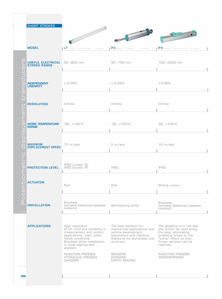
P K
SHORT STROKESP
ote
nti
om
etr
ic d
ispla
cem
ent
transducers
06
50..900 mm 50..750 mm 100..2000 mm
± 0.05% ± 0.05%
Infinite
-30..+100°C
10 m/sec 5 m/sec 10 m/sec
IP60 (model -S)IP65 (model -P) IP65 IP40
Rod Sliding cursor
Brackets(variable distances betweencenters)
Self-aligning jointsBrackets(variable distances betweencenters)
High resolution(0.01 mm) and reliabil ity inmeasurement and controlapplications, even underharsh conditions.Brackets allow installationin most appropriateposition.
INJECTION PRESSESHYDRAULIC PRESSESSANDERS
The best solution formechanical applications andvehicle development,automation and robotics,thanks to its sturdiness andaccuracy.
BENDERSSANDERSEARTH MOVING
The absence of a rod letsthe cursor be used alongthe axis, eliminatingproblems linked to the“pump” effect so thatlonger strokes can bereached.
INJECTION PRESSESWOODWORKING
Infinite Infinite
± 0.05%
-30..+100°C -30..+100°C
Rod
P CLT
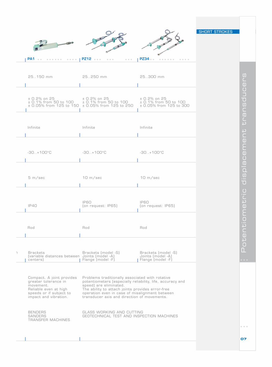
PA1 PZ12 PZ34
SHORT STROKES
Pote
nti
om
etr
ic d
ispla
cem
ent
transducers
07
n
25..150 mm 25..250 mm 25..300 mm
± 0.2% on 25± 0.1% from 50 to 100± 0.05% from 125 to 150
± 0.2% on 25± 0.1% from 50 to 100± 0.05% from 125 to 250
± 0.2% on 25± 0.1% from 50 to 100± 0.05% from 125 to 300
Infinite
-30..+100°C
5 m/sec 10 m/sec
IP40IP60(on request: IP65)
Rod
Brackets(variable distances betweencenters)
Brackets (model -S)Joints (model -A)Flange (model -F)
Compact. A joint providesgreater tolerance inmovement.Reliable even at highspeeds or if subject toimpact and vibration.
BENDERSSANDERSTRANSFER MACHINES
Problems traditionally associated with rotativepotentiometers (especially reliability, life, accuracy andspeed) are eliminated.The abil ity to attach joints provides error-freeoperation even in case of misalignment betweentransducer axis and direction of movements.
GLASS WORKING AND CUTTINGGEOTECHNICAL TEST AND INSPECTION MACHINES
Infinite Infinite
-30..+100°C -30..+100°C
Rod Rod
IP60(on request: IP65)
10 m/sec
Brackets (model -S)Joints (model -A)Flange (model -F)
PY1 PY2 PY3
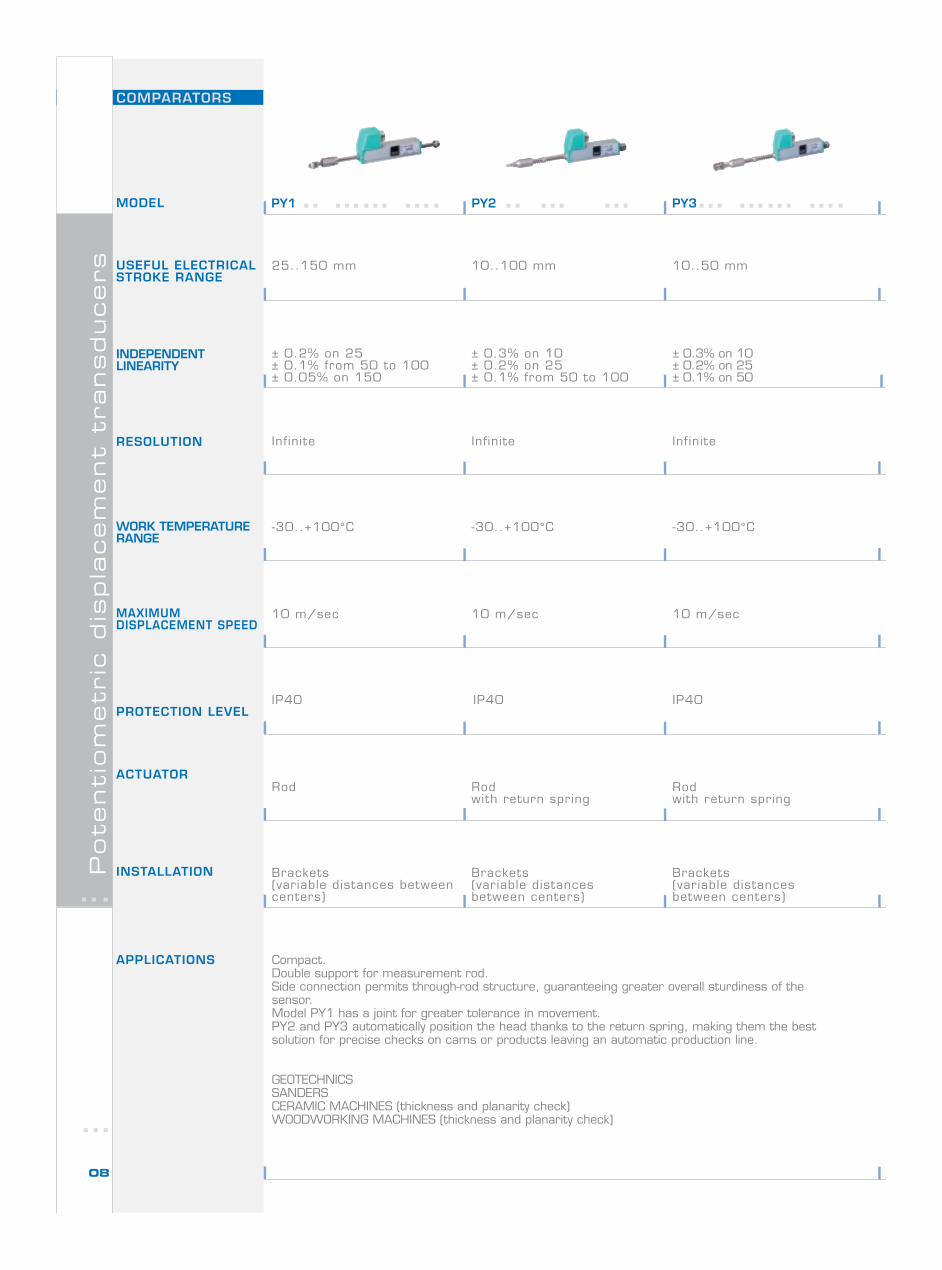
COMPARATORSP
ote
nti
om
etr
ic d
ispla
cem
ent
transducers
08
25..150 mm 10..100 mm 10..50 mm
± 0.3% on 10± 0.2% on 25± 0.1% from 50 to 100
± 0.3% on 10± 0.2% on 25± 0.1% on 50
Infinite
-30..+100°C
10 m/sec
IP40
Rodwith return spring
Brackets(variable distancesbetween centers)
Compact.Double support for measurement rod.Side connection permits through-rod structure, guaranteeing greater overall sturdiness of thesensor.Model PY1 has a joint for greater tolerance in movement.PY2 and PY3 automatically position the head thanks to the return spring, making them the bestsolution for precise checks on cams or products leaving an automatic production line.
GEOTECHNICSSANDERSCERAMIC MACHINES (thickness and planarity check)WOODWORKING MACHINES (thickness and planarity check)
± 0.2% on 25± 0.1% from 50 to 100± 0.05% on 150
Rod
Infinite Infinite
-30..+100°C -30..+100°C
10 m/sec 10 m/sec
IP40 IP40
Rodwith return spring
Brackets(variable distances betweencenters)
Brackets(variable distancesbetween centers)
MODEL
USEFUL ELECTRICALSTROKE RANGE
INDEPENDENTLINEARITY
RESOLUTION
WORK TEMPERATURERANGE
MAXIMUMDISPLACEMENT SPEED
PROTECTION LEVEL
ACTUATOR
INSTALLATION
APPLICATIONS
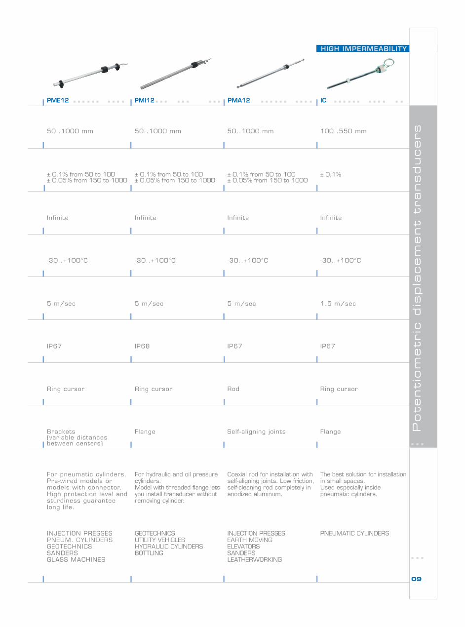
PME12 PMI12 PMA12
HIGH IMPERMEABILITY
IC
Pote
nti
om
etr
ic d
ispla
cem
ent
transducers
09
50..1000 mm
5 m/sec
IP67
Brackets(variable distancesbetween centers)
For pneumatic cylinders.Pre-wired models ormodels with connector.High protection level andsturdiness guaranteelong life.
INJECTION PRESSESPNEUM. CYLINDERSGEOTECHNICSSANDERSGLASS MACHINES
± 0.1% from 50 to 100± 0.05% from 150 to 1000
-30..+100°C
1.5 m/sec
IP68
Ring cursor
Flange
For hydraulic and oil pressurecylinders.Model with threaded flange letsyou install transducer withoutremoving cylinder.
GEOTECHNICSUTILITY VEHICLESHYDRAULIC CYLINDERSBOTTLING
100..550 mm
IP67 IP67
Rod Ring cursor
Self-aligning joints Flange
Coaxial rod for installation withself-aligning joints. Low friction,self-cleaning rod completely inanodized aluminum.
INJECTION PRESSESEARTH MOVINGELEVATORSSANDERSLEATHERWORKING
The best solution for installationin small spaces.Used especially insidepneumatic cylinders.
PNEUMATIC CYLINDERS
50..1000 mm 50..1000 mm
± 0.1% from 50 to 100± 0.05% from 150 to 1000
± 0.1% from 50 to 100± 0.05% from 150 to 1000
± 0.1%
-30..+100°C -30..+100°C -30..+100°C
5 m/sec5 m/sec
Infinite Infinite Infinite Infinite
Ring cursor
SHORT STROKES
Magneto
str
icti
ve d
ispla
cem
ent
transducers
10
MODEL
USEFUL ELECTRICALSTROKE RANGE
INDEPENDENTLINEARITY
RESOLUTION
WORK TEMPERATURERANGE
DISPLACEMENTSPEED
PROTECTIONLEVEL
TIPO ATTUATORE
MOUNTING
APPLICATIONS
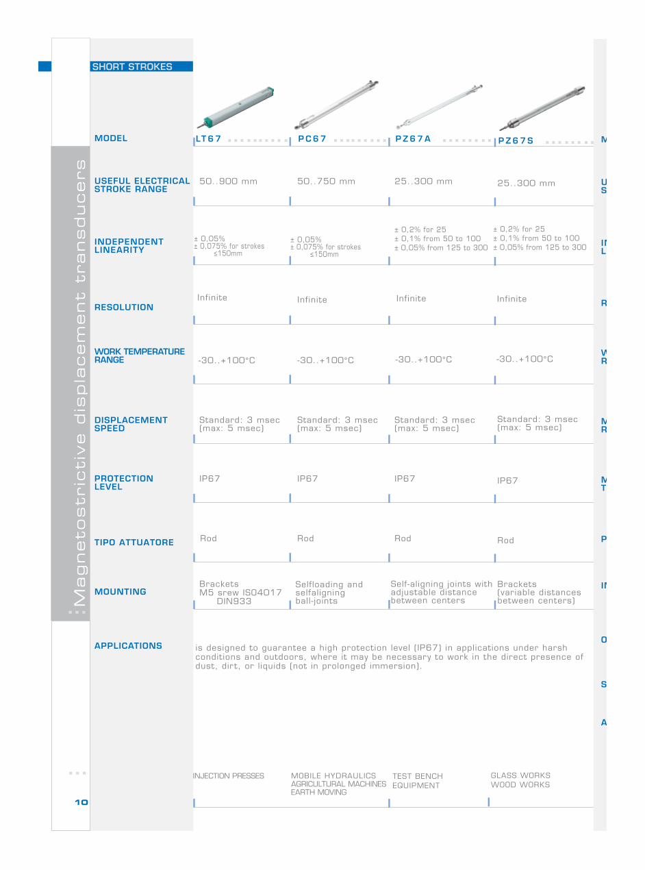
P C 6 7LT 6 7 P Z 6 7 A P Z 6 7 S
MOBILE HYDRAULICSAGRICULTURAL MACHINESEARTH MOVING
M
US
INL
R
WR
MR
MT
P
IN
A
O
S
50..900 mm 50..750 mm
± 0,05%± 0,075% for strokes ≤150mm
Infinite
-30..+100°C
Standard: 3 msec(max: 5 msec)
Standard: 3 msec(max: 5 msec)
IP67 IP67
Rod
BracketsM5 srew ISO4017 DIN933
Selfloading andselfaligningball- joints
is designed to guarantee a high protection level (IP67) in applications under harshconditions and outdoors, where it may be necessary to work in the direct presence ofdust, dir t, or l iquids (not in prolonged immersion).
25..300 mm
± 0,2% for 25± 0,1% from 50 to 100± 0,05% from 125 to 300
Standard: 3 msec(max: 5 msec)
IP67
Rod
Self-aligning joints withadjustable distancebetween centers
25..300 mm
Standard: 3 msec(max: 5 msec)
IP67
Rod
Brackets(variable distancesbetween centers)
± 0,05%± 0,075% for strokes ≤150mm
± 0,2% for 25± 0,1% from 50 to 100± 0,05% from 125 to 300
Infinite Infinite Infinite
-30..+100°C -30..+100°C -30..+100°C
Rod
TEST BENCHEQUIPMENT
INJECTION PRESSES GLASS WORKSWOOD WORKS
Rota
tive d
ispla
cem
ent
transducers
11
MODEL
USEFUL ELECTRICALSTROKE RANGE
INDEPENDENTLINEARITY
RESOLUTION
WORK TEMPERATURERANGE
MAXIMUMROTATION SPEED
MAXIMUMTORQUE
PROTECTION LEVEL
INSTALLATION
APPLICATIONS
OUTSIDE DIAMETER
SHAFT DIAMETER
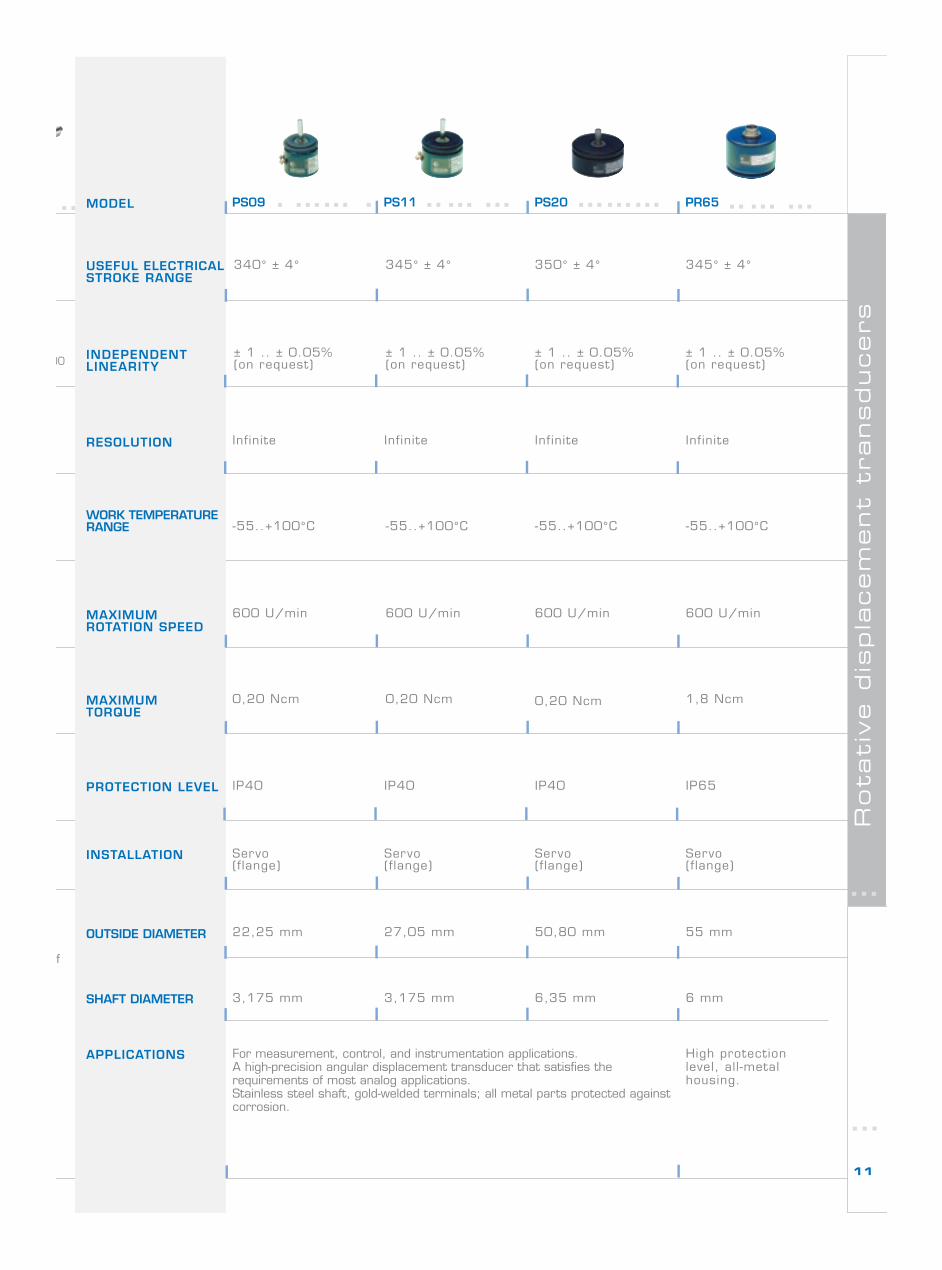
PS09 PS11 PS20 PR65
340° ± 4° 345° ± 4° 350° ± 4°
± 1 .. ± 0.05%(on request)
± 1 .. ± 0.05%(on request)
-55..+100°C
600 U/min
0,20 Ncm
For measurement, control, and instrumentation applications.A high-precision angular displacement transducer that satisfies therequirements of most analog applications.Stainless steel shaft, gold-welded terminals; all metal parts protected againstcorrosion.
± 1 .. ± 0.05%(on request)
IP40
0,20 Ncm
345° ± 4°
± 1 .. ± 0.05%(on request)
Infinite
-55..+100°C -55..+100°C -55..+100°C
600 U/min 600 U/min 600 U/min
0,20 Ncm 1,8 Ncm
Servo(flange)
22,25 mm
Infinite Infinite Infinite
IP40 IP40 IP65
Servo(flange)
Servo(flange)
Servo(flange)
27,05 mm 50,80 mm 55 mm
3,175 mm 3,175 mm 6,35 mm 6 mm
High protectionlevel, all-metalhousing.
f
00
MODEL
USEFUL ELECTRICALSTROKE RANGE
INDEPENDENTLINEARITY
RESOLUTION
WORK TEMPERATURERANGE
MAXIMUMDISPLACEMENTSPEED
INTERFACE
MEASUREMENTTAKEN
PROTECTION LEVEL
INSTALLATION
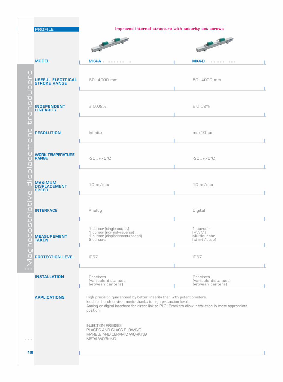
MK4-A
PROFILE
APPLICATIONS
Magneto
str
icti
ve d
ispla
cem
ent
transducers
50..4000 mm
High precision guaranteed by better linearity than with potentiometers.Ideal for harsh environments thanks to high protection level.Analog or digital interface for direct link to PLC. Brackets allow installation in most appropriateposition.
INJECTION PRESSESPLASTIC AND GLASS BLOWINGMARBLE AND CERAMIC WORKINGMETALWORKING
± 0,02%
1 cursor (single output)1 cursor (normal+reverse)1 cursor (displacement+speed)2 cursors
Infinite
-30..+75°C
10 m/sec
Analog
IP67
Brackets(variable distancesbetween centers)
12
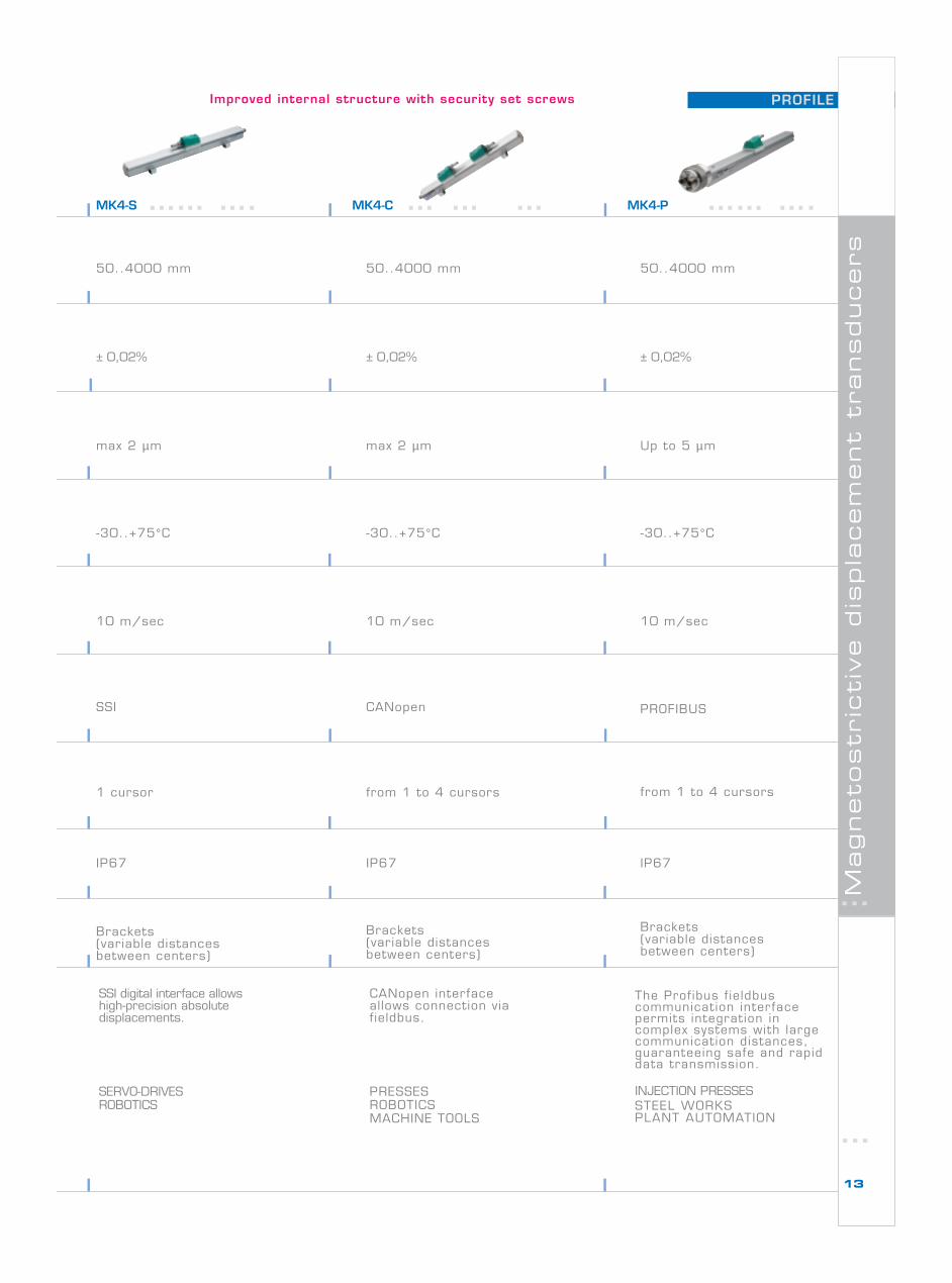
Improved internal structure with security set screws
MK4-D
50..4000 mm
± 0,02%
max10 µm
-30..+75°C
10 m/sec
Digital
IP67
Brackets(variable distancesbetween centers)
1 cursor(PWM)Multicursor(start/stop)
PROFILE
Magneto
str
icti
ve d
ispla
cem
ent
transducers
13
Improved internal structure with security set screws
50..4000 mm
10 m/sec
-30..+75°C
Brackets(variable distancesbetween centers)
SSI digital interface allowshigh-precision absolutedisplacements.
SERVO-DRIVESROBOTICS
CANopen interfaceallows connection viafieldbus.
PRESSESROBOTICSMACHINE TOOLS
50..4000 mm 50..4000 mm
± 0,02% ± 0,02% ± 0,02%
max 2 µm max 2 µm Up to 5 µm
-30..+75°C-30..+75°C
10 m/sec 10 m/sec
CANopen PROFIBUSSSI
1 cursor from 1 to 4 cursors from 1 to 4 cursors
IP67 IP67 IP67
Brackets(variable distancesbetween centers)
Brackets(variable distancesbetween centers)
The Prof ibus f ie ldbuscommunication inter facepermits integration incomplex systems with largecommunication distances,guaranteeing safe and rapiddata transmission.
INJECTION PRESSESSTEEL WORKSPLANT AUTOMATION
MK4-C MK4-PMK4-S
MODEL
USEFUL ELECTRICALSTROKE RANGE
INDEPENDENTLINEARITY
RESOLUTION
WORK TEMPERATURERANGE
MAXIMUMDISPLACEMENTSPEED
INTERFACE
MEASUREMENTTAKEN
PROTECTION LEVEL
INSTALLATION
ROD
APPLICATIONS
Magneto
str
icti
ve d
ispla
cem
ent
transducers
14
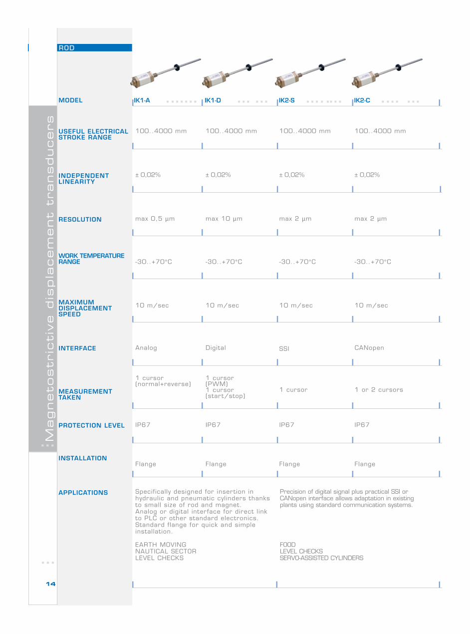
IK2-CIK2-SIK1-DIK1-A
100..4000 mm
10 m/sec
Specifically designed for insertion inhydraulic and pneumatic cylinders thanksto small size of rod and magnet.Analog or digital interface for direct l inkto PLC or other standard electronics.Standard flange for quick and simpleinstallation.
EARTH MOVINGNAUTICAL SECTORLEVEL CHECKS
-30..+70°C
Flange
Precision of digital signal plus practical SSI orCANopen interface allows adaptation in existingplants using standard communication systems.
FOODLEVEL CHECKSSERVO-ASSISTED CYLINDERS
100..4000 mm 100..4000 mm 100..4000 mm
± 0,02% ± 0,02% ± 0,02% ± 0,02%
max 0,5 µm max 10 µm max 2 µm max 2 µm
-30..+70°C-30..+70°C -30..+70°C
10 m/sec 10 m/sec 10 m/sec
Digital SSIAnalog CANopen
1 cursor(normal+reverse)
1 cursor(PWM)1 cursor(start/stop)
1 cursor 1 or 2 cursors
IP67 IP67 IP67 IP67
Flange Flange Flange
ROD
Magneto
str
icti
ve d
ispla
cem
ent
transducers
15
The Prof ibus f ie ldbuscommunication inter facepermits integration incomplex systems with largecommunication distances,guaran-teeing safe and rapiddata transmission.
HYDRAULIC SYSTEMS FORPLANT AUTOMATION
Flange
50..4000 mm
± 0,02%
max 5 µm
-30..+75°C
10 m/sec
PROFIBUS
From 1 to 4 cursors
IP67
IK2-P IK4-C
-30..+75°C
50..4000 mm
± 0,02%
max 2 µm
10 m/sec
CANopen
IP67
Flange
50..4000 mm
10 m/sec
± 0,02%
infinie
-30..+75°C
Analog
1 cursor (normal+reverse)
IP67
Flange
IK4-A
HYDRAULIC SYSTEMS FOR PLANTAUTOMATIONINDUSTRIAL HYDRAULICSLEVEL CHECKS
The IK4 line’s new mechanical structure offers improved features for in-cylinderuse, including a series of new multi-connector models, free rotation of the connectorhead, and replacement of internal electronics without removal of the transducer.
From 1 to 4 cursors(displacement+speed)
Magneto
str
icti
ve d
ispla
cem
ent
transducers
16
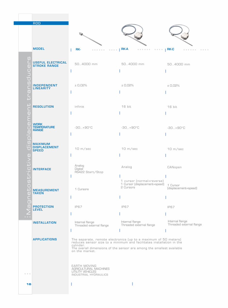
The separate, remote electronics (up to a maximum of 50 meters)reduces sensor size to a minimum and faci l i tates instal lat ion in thecyl inder.The overall dimensions of the sensor are among the smallest availableon the market.
EARTH MOVINGAGRICULTURAL MACHINESUTILITY VEHICLESINDUSTRIAL HYDRAULICS
50..4000 mm
10 m/sec
± 0,02%
infinie
-30..+90°C
AnalogDigitalRS422 Start/Stop
1 Cursore
IP67
Internal flangeThreaded external flange
ROD
MODEL
USEFUL ELECTRICALSTROKE RANGE
INDEPENDENTLINEARITY
RESOLUTION
WORKTEMPERATURERANGE
MAXIMUMDISPLACEMENTSPEED
INTERFACE
MEASUREMENTTAKEN
PROTECTIONLEVEL
INSTALLATION
APPLICATIONS
RK- RK-A
-30..+90°C
50..4000 mm
± 0,02%
16 bit
10 m/sec
Analog
1 cursor (normal+reverse)1 Cursor (displacement+speed)2 Cursors
IP67
RK-C
-30..+90°C
50..4000 mm
± 0,02%
16 bit
10 m/sec
CANopen
1 Cursor(displacement+speed)
IP67
Internal flangeThreaded external flange
Internal flangeThreaded external flange
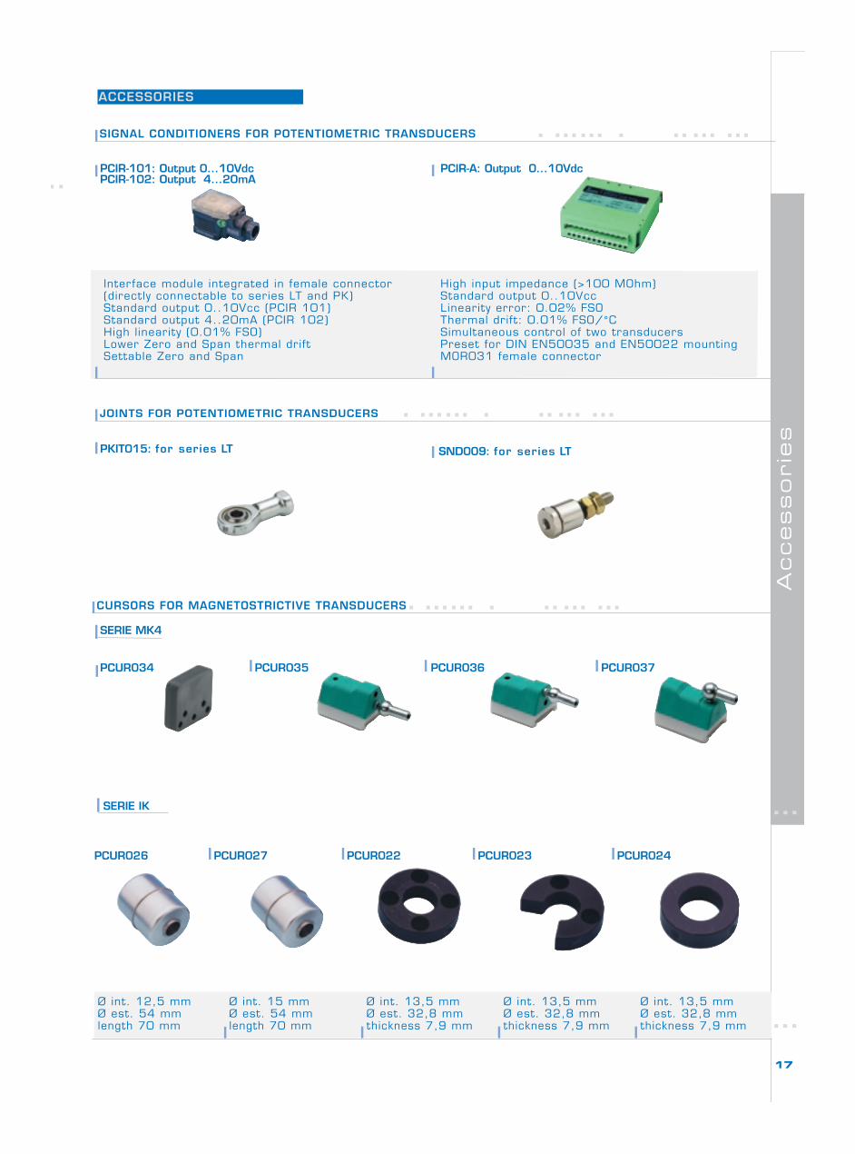
ACCESSORIES
Accessorie
s
17
CURSORS FOR MAGNETOSTRICTIVE TRANSDUCERS
Ø int. 12,5 mmØ est. 54 mmlength 70 mm
Ø int. 15 mmØ est. 54 mmlength 70 mm
Ø int. 13,5 mmØ est. 32,8 mmthickness 7,9 mm
Ø int. 13,5 mmØ est. 32,8 mmthickness 7,9 mm
Ø int. 13,5 mmØ est. 32,8 mmthickness 7,9 mm
JOINTS FOR POTENTIOMETRIC TRANSDUCERS
High input impedance (>100 MOhm)Standard output 0..10VccLinearity error: 0.02% FSOThermal drift: 0.01% FSO/°CSimultaneous control of two transducersPreset for DIN EN50035 and EN50022 mountingMOR031 female connector
SIGNAL CONDITIONERS FOR POTENTIOMETRIC TRANSDUCERS
PCIR-101: Output 0...10VdcPCIR-102: Output 4...20mA
PCIR-A: Output 0...10Vdc
PKIT015: for series LT SND009: for series LT
SERIE IK
Interface module integrated in female connector(directly connectable to series LT and PK)Standard output 0..10Vcc (PCIR 101)Standard output 4..20mA (PCIR 102)High linearity (0.01% FSO)Lower Zero and Span thermal driftSettable Zero and Span
PCUR026 PCUR027 PCUR022 PCUR023 PCUR024
SERIE MK4
PCUR034 PCUR035 PCUR036 PCUR037
Accessorie
s
18
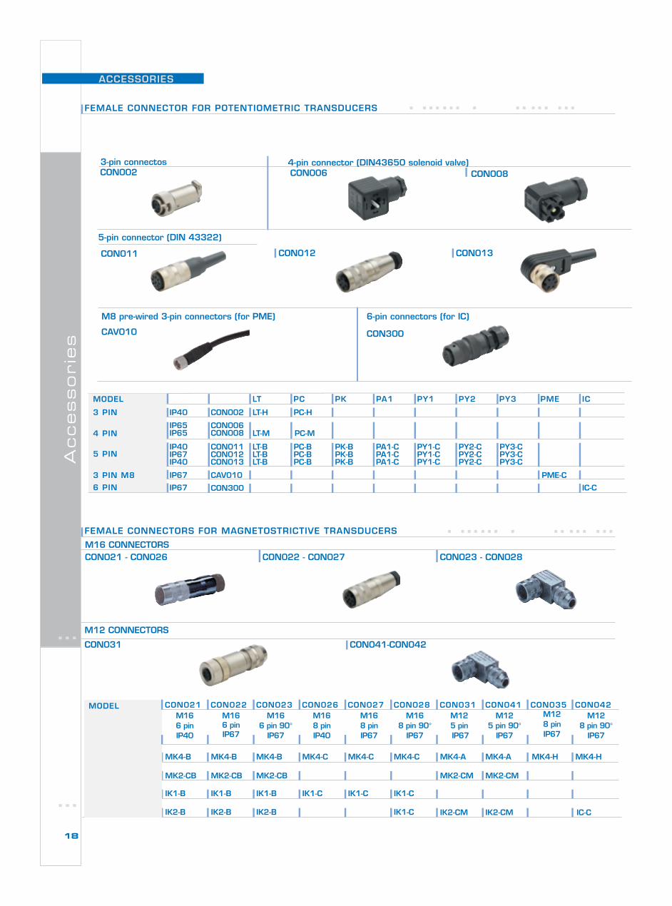
ACCESSORIES
CON0024-pin connector (DIN43650 solenoid valve)
3 PIN
4 PIN
5 PIN
3 PIN M8
6 PIN
MODEL LT PC PK PA1 PY1 PY2 PY3 PME IC
IP40 CON002 LT-H PC-H
IP65IP65
CON006CON008 LT-M PC-M
IP40IP67IP40
CON011CON012CON013
LT-BLT-BLT-B
PC-BPC-BPC-B
PK-BPK-BPK-B
PA1-CPA1-CPA1-C
PY1-CPY1-CPY1-C
PY2-CPY2-CPY2-C
PY3-CPY3-CPY3-C
IP67 CON300 IC-C
IP67 PME-CCAV010
3-pin connectosCON006
M8 pre-wired 3-pin connectors (for PME) 6-pin connectors (for IC)
CAV010
CON011 CON012 CON013
CON008
CON300
IK2 IC-CIK2-CM IK2-CMIK2-B IK1-CIK2-B IK2-B
IK1 IK1-B IK1-B IK1-B IK1-C IK1-C IK1-C
MK2 MK2-CB MK2-CB MK2-CB MK2-CM MK2-CM
MK4 MK4-B MK4-B MK4-B MK4-C MK4-C MK4-C MK4-A MK4-A MK4-HMK4-H
MODEL CON021 CON022 CON023 CON026 CON027 CON028 CON031 CON041 CON035 CON042M166 pinIP40
M166 pinIP67
M166 pin 90°
IP67
M168 pinIP40
M168 pinIP67
M168 pin 90°
IP67
M125 pin IP67
M125 pin 90°
IP67
M128 pinIP67
M128 pin 90°
IP67
5-pin connector (DIN 43322)
FEMALE CONNECTOR FOR POTENTIOMETRIC TRANSDUCERS
M12 CONNECTORS
FEMALE CONNECTORS FOR MAGNETOSTRICTIVE TRANSDUCERS
M16 CONNECTORSCON021 - CON026 CON022 - CON027 CON023 - CON028
CON031 CON041-CON042
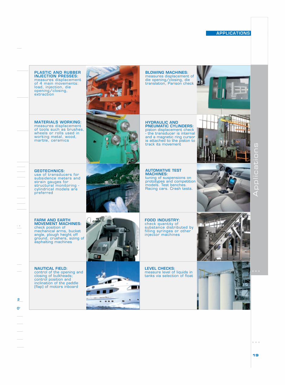
APPLICATIONS
Applicati
ons
19
2
0°
PLASTIC AND RUBBERINJECTION PRESSES:measures displacementof 4 main movements:load, injection, dieopening/closing,extraction
MATERIALS WORKING:measures displacementof tools such as brushes,wheels or rolls used inworking metal, wood,marble, ceramics
GEOTECHNICS:use of transducers forsubsidence meters andstrain gauges forstructural monitoring -cylindrical models arepreferred
FARM AND EARTHMOVEMENT MACHINES:check position ofmechanical arms, bucketangle, plough height offground, crushers, sizing ofasphalting machines
NAUTICAL FIELD:control of the opening andclosing of bulkheads;control position andinclination of the paddle(flap) of motors inboard
BLOWING MACHINES:measures displacement ofdie opening/closing, dietranslation, Parison check
HYDRAULIC ANDPNEUMATIC CYLINDERS:piston displacement check- the transducer is internaland a magnetic ring cursoris attached to the piston totrack its movement
AUTOMATIVE TESTMACHINES:tuning of suspensions onprototypes and competitionmodels. Test benches.Racing cars. Crash tests.
FOOD INDUSTRY:check quantity ofsubstance distributed byfi l l ing syringes or otherinjector machines
LEVEL CHECKS:measure level of liquids intanks via selection of float

COD
. 80411
F - 0
8/
07
www.ge f ran . comwww.ge f rans i e i . com
HeadquarterGEFRAN SpaVia Sebina, 7425050 PROVAGLIO D’ISEO (BS)ITALYPh. +39 03098881Fax +39 [email protected]
Our Know how,Your Solution.
Drive & Motion Control UnitVia Carducci, 2421040 GERENZANO (VA) ITALYPh. +39 02967601Fax +39 [email protected]
CERTIFICAZIONE DEI SISTEMIQUALITÀ DELLE AZIENDE
G E F R A N
UNI EN ISO 9001CERTIFICATO nr. 9115 GEF1
ArgentinaAustriaAustraliaBulgariaCanadaChileCyprusColombiaCzech RepublicDenmarkEgyptFinlandGreeceHong KongHungaryIndia
IranIsraelJapanJordanKoreaLebanonMalaysiaMarocMexicoNew ZealandNorwayPeruPolandPortugalRumaniaRussia
Saudi ArabiaSingaporeSlovakia RepublicSloveniaSouth AfricaSpainSwedenTaiwanThailandTunisiaTurkeyUkraineUnited Arab EmiratesVenezuela
AUTHORIZED DISTRIBUTORS
GEFRAN BENELUXLammerdries, 14AB-2250 OLENPh. +32 (0) 14248181Fax. +32 (0) [email protected]
GEFRAN BRASILELETROELETRÔNICAAvenida Dr. Altino Arantes,377/379 Vila Clementino04042-032 SÂO PAULO - SPPh. +55 (0) 1155851133Fax +55 (0) [email protected]
GEFRAN DEUTSCHLANDPhilipp-Reis-Straße 9a63500 SELIGENSTADTPh. +49 (0) 61828090Fax +49 (0) [email protected]
GEFRAN SUISSERue Fritz Courvoisier, 402302 LA CHAUX-DE-FONDSPh. +41 (0) 329684955Fax +41 (0) [email protected]
SIEI AREG - GERMANYZachersweg, 17D 74376 - GemmrigheimPh. +49 7143 9730Fax +49 7143 [email protected]
GEFRAN Inc.8 Lowell AvenueWINCHESTER - MA 01890Toll Free 1-888-888-4474Ph. +1 (781) 7295249Fax +1 (781) [email protected]
14201 D South Lakes DriveCHARLOTTE - NC 28273Ph. +1 (704) 3290200Fax +1 (704) [email protected]
GEFRAN SIEI - UK Ltd7 Pearson Road - Central ParkTelford - TF2 9TXPh. +44 (0) 8452 604555Fax +44 (0) 8452 [email protected]@sieiuk.co.uk
GEFRAN FRANCE4, rue Jean Desparmet - BP 823769355 LYON Cedex 08Ph. +33 (0) 478770300Fax +33 (0) [email protected]@sieifrance.fr
GEFRAN SIEI - ASIABlk.30 Loyang Way03-19 Loyang Industrial Estate508769 SingaporePh. +65 6 8418300Fax +65 6 [email protected]
SIEI DRIVES TECHNOLOGYNo.1265, B1, Hong De Road,Jia Ding District201821 ShanghaiPh. +86 21 69169898Fax +86 21 [email protected]
GEFRAN SIEI Electric Pte LtdBlock B, Gr.Flr, No.155, Fu Te XiYi Road,Wai Gao Qiao Trade ZoneShanghai, 200131Ph. +86 21 5866 7816Ph. +86 21 5866 [email protected]