Embed Size (px)
Citation preview
Distensible Diameter Sheath
Volume 1
University of Minnesota
Department of Mechanical Engineering
ME 4054W: Design Projects, Spring 2013
Team Members
Elliott Jons Connor Mulcahy
Danny Vang Adam Weimerskirch
Scott Wobschall
Project Advisor
Douglas H. Post
Special Thanks
University of Minnesota Medical Device Center
Executive Summary
Patients who require heart valve replacement but are poor candidates for open-heart surgery often undergo Transcatheter Aortic Valve Implantation (TAVI) procedures, in which the replacement valve is delivered to the heart through the femoral artery (near the inner thigh). However, some patients are precluded from TAVI procedures because their femoral arteries are too narrow (in some cases narrower than the valve itself) for the valve to pass through without dangerous levels of shear force on the artery. The purpose of this project was to design a sheath which would shield the femoral artery from shear force as the valve passes into the aorta. The key requirements of the sheath were that it would allow a 6 mm diameter valve to pass through a 6 mm diameter femoral artery without excessive force exerted on either the artery or the valve, and would satisfy procedural requirements of a TAVI. The goal of the project was to develop a prototype to serve as a proof-of-concept, and to show that committing additional resources to further develop the prototype into a commercial product would be worthwhile.
A radially expandable sheath was developed, which is introduced into the femoral artery with a smaller diameter than the artery, and then distends locally around the valve as it passes through the sheath. This subjects the artery to a radial force, which it is suited to handle, instead of a shear force. The expandable section of the sheath consists of a radially expandable mesh with wires woven in longitudinally and a watertight PTFE outer layer to allow air to be flushed from the sheath prior to insertion into the artery. The expandable sheath is introduced into the artery inside a tubular outer layer which is removed from the body prior to passage of the valve. The expandable sheath is radially compliant, but has enough longitudinal rigidity to allow the valve to be passed through the sheath.
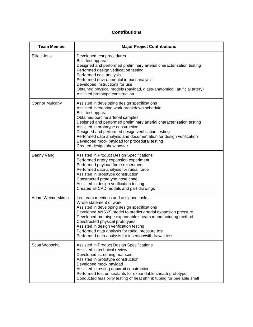
A physical prototype was used to verify that the procedural requirements were met by demonstrating a mock procedure in a model of the femoral artery. The force requirements were evaluated through experiments with the physical prototype and engineering analysis. Recommendations for future prototypes were developed and their effects on the overall design were assessed. The goal of providing proof-of-concept for the design was achieved. Further development of the prototype is required to reduce friction and assess whether large scale production of the product would be technically and economically feasible.
Specification Units Allowable Value Prototype Value After Recommendations
Radial Force on Payload kPa 3300 83.2 83.2
Payload Insertion Force N 3.6 8.7 2.5
Payload Withdraw Force N 4.3 6.7 1.7
Contributions
Team Member Major Project Contributions
Elliott Jons Developed test procedures Built test apparati Designed and performed preliminary arterial characterization testing Performed design verification testing Performed cost analysis Performed environmental impact analysis Developed instructions for use Obtained physical models (payload, glass-anatomical, artificial artery) Assisted prototype construction
Connor Mulcahy Assisted in developing design specifications Assisted in creating work breakdown schedule Built test apparati Obtained porcine arterial samples Designed and performed preliminary arterial characterization testing Assisted in prototype construction Designed and performed design verification testing Performed data analysis and documentation for design verification Developed mock payload for procedural testing Created design show poster
Danny Vang Assisted in Product Design Specifications Performed artery expansion experiment Performed payload force experiment Performed data analysis for radial force Assisted in prototype construction Constructed prototype nose cone Assisted in design verification testing Created all CAD models and part drawings
Adam Weimerskirch
Led team meetings and assigned tasks Wrote statement of work Assisted in developing design specifications Developed ANSYS model to predict arterial expansion pressure Developed prototype expandable sheath manufacturing method Constructed physical prototypes Assisted in design verification testing Performed data analysis for radial pressure test Performed data analysis for insertion/withdrawal test
Scott Wobschall Assisted in Product Design Specifications Assisted in technical review Developed screening matrices Assisted in prototype construction Developed mock payload Assisted in testing apparati construction Performed test on sealants for expandable sheath prototype Conducted feasibility testing of heat shrink tubing for peelable shell
Team Member Design Report Contributions
Elliott Jons Volume I: Wrote sections: 1.2, 2.3, 3.2.2, 3.2.4, 3.3.2
Assisted in writing sections: 3.2.1, 3.2.5 Edited all sections
Volume II: Wrote sections: 2.1.5, 2.1.6, 3.1.4, 3.2, 3.3 Assisted in writing sections: 1.1, 3.1.1, 3.1.3 Edited all sections
Connor Mulcahy Volume I: Wrote sections: 3.2.3, 3.3.1, 3.2.5 Assisted in writing sections: 3.2.2, 3.2.4 Edited all sections Volume II: Wrote sections: 1.1, 1.6, 3.1.2, 3.1.4, 3.1.5, 3.1.6 Assisted in writing sections: 3.1.3 Edited all sections
Danny Vang Volume I: Constructed title page Created all CAD diagrams Edited all sections
Volume II: Constructed title page Created all CAD diagrams Created all part drawings Wrote sections: 1.2, 3.4 Edited all sections
Adam Weimerskirch Coordinated report work Volume I:
Wrote executive summary Wrote sections: 1.1, 1.3, 2.1, 2.2, 3.1 Assisted in writing sections: 3.2.1, 3.2.3, 3.2.4 Edited all sections
Volume II: Wrote sections: 1.4, 2.1.1, 2.1.4 Assisted in writing sections 2.1.5, 3.1.3, 3.5 Edited all sections
Scott Wobschall Volume I: Wrote sections: 1.2 Assisted in writing sections: 3.1 Edited all sections
Volume II: Wrote Sections: 1.5, 2.1.3, 3.5 Assisted in writing sections: 1.1, 1.3, 1.4 Edited all sections
Note: Any contributions not included here were performed by all members of the group.
Table of Contents
1. Problem Definition ................................................................................................... 1
1.1 Problem Scope .............................................................................................................. 1
1.2 Technical Review ........................................................................................................... 1
1.3 Design Requirements ..................................................................................................... 3
1.3.1 Diametral Strain of Artery .................................................................................................... 3
1.3.2 Diameter of Expandable Sheath During Insertion .............................................................. 4
1.3.3 Radial Pressure Exerted on Payload .................................................................................. 4
1.3.4 Force Required to Insert and Withdraw Payload ................................................................ 4
1.3.5 Minimum Bend Radius without Kinking............................................................................... 4
2. Design Description .................................................................................................. 5
2.1 Summary of the Design .................................................................................................. 5
2.2 Detailed Description ....................................................................................................... 7
2.2.1 Functional Description ...................................................................................................... 10
2.3 Additional Uses ............................................................................................................ 13
3. Evaluation ............................................................................................................... 14
3.1 Evaluation Plan ............................................................................................................ 14
3.2 Evaluation Results ....................................................................................................... 15
3.2.1 Strain Induced on Artery During Passage of Payload ...................................................... 15
3.2.2 Diameter of Expandable Sheath Assembly Prior to Insertion ........................................... 16
3.2.3 Radial Pressure Exerted on Payload ................................................................................ 16
3.2.4 Force Required for Payload Insertion and Withdrawal ..................................................... 18
3.2.5 Minimum Bend Radius without Kinking............................................................................. 18
3.3 Discussion ................................................................................................................... 19
3.3.1 Strengths and Weaknesses .............................................................................................. 19
3.3.2 Next Steps ......................................................................................................................... 20
1
1 Problem Definition
1.1 Problem Scope
Patients who require heart valve replacement but are poor candidates for open-heart surgery
often undergo Transcatheter Aortic Valve Implantation (TAVI) procedures, in which the
replacement valve is inserted into the femoral artery (near the thigh) and is delivered to the
heart using a catheter[15]. However, some patients’ femoral arteries are too small for the valve
to pass through. The primary objective of this project was to design, and evaluate an
expandable sheath prototype which would allow a heart valve to be safely passed through these
smaller femoral arteries and into the aorta. This requires the expandable sheath to be inserted
into the femoral artery in a compressed state, to expand as the valve passes through, and to
return to the unexpanded state for removal from the artery.
1.2 Technical Review
The aortic valve is between the left ventricle of the heart and the aorta. Aortic stenosis is a
heart valve disease in which the opening of the aortic valve is narrowed. The narrowing of this
valve restricts outflow of blood causing the heart to work harder [17]. If left untreated, aortic
stenosis can lead to heart failure [17]. Of the patients suffering from serious aortic stenosis, 27-
41% do not receive surgical replacement for reasons ranging from patient refusal to a doctor
deeming a patient inoperable [13]. Aortic stenosis can be caused by a birth defect, calcium
buildup, or rheumatic fever leading to scar tissue [16]. Aortic stenosis often takes years for
symptoms to surface. Birth defects become apparent in young patients as they become adults
and their hearts are required to pump more blood. Symptoms from plaque buildup can take
many years to surface, often not showing in patients until the age of 65 [17]. Of people age 75
and older, 4.6% of adults have aortic stenosis and life expectancy for people that are affected
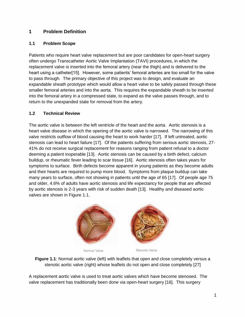
by aortic stenosis is 2-3 years with risk of sudden death [13]. Healthy and diseased aortic
valves are shown in Figure 1.1.
Figure 1.1: Normal aortic valve (left) with leaflets that open and close completely versus a
stenotic aortic valve (right) whose leaflets do not open and close completely [27]
A replacement aortic valve is used to treat aortic valves which have become stenosed. The
valve replacement has traditionally been done via open-heart surgery [16]. This surgery
2
requires that an incision be made in the sternum and the patient is put on a cardiopulmonary
bypass machine during the procedure. TAVI is a newer technology for treating aortic stenosis.
Similarly to open-heart surgery, the purpose of a TAVI procedure is to replace the faulty heart
valve with a properly functioning artificial heart valve. The benefit to TAVI procedures is that
they are minimally invasive. This can be beneficial in treating patients for whom open-heart
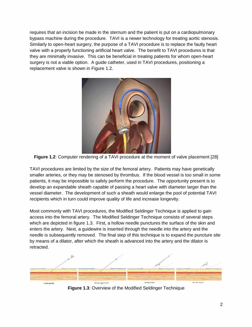
surgery is not a viable option. A guide catheter, used in TAVI procedures, positioning a
replacement valve is shown in Figure 1.2.
Figure 1.2: Computer rendering of a TAVI procedure at the moment of valve placement [28]
TAVI procedures are limited by the size of the femoral artery. Patients may have genetically
smaller arteries, or they may be stenosed by thrombus. If the blood vessel is too small in some
patients, it may be impossible to safely perform the procedure. The opportunity present is to
develop an expandable sheath capable of passing a heart valve with diameter larger than the
vessel diameter. The development of such a sheath would enlarge the pool of potential TAVI
recipients which in turn could improve quality of life and increase longevity.
Most commonly with TAVI procedures, the Modified Seldinger Technique is applied to gain
access into the femoral artery. The Modified Seldinger Technique consists of several steps
which are depicted in figure 1.3. First, a hollow needle punctures the surface of the skin and
enters the artery. Next, a guidewire is inserted through the needle into the artery and the
needle is subsequently removed. The final step of this technique is to expand the puncture site
by means of a dilator, after which the sheath is advanced into the artery and the dilator is
retracted.
Figure 1.3: Overview of the Modified Seldinger Technique
3
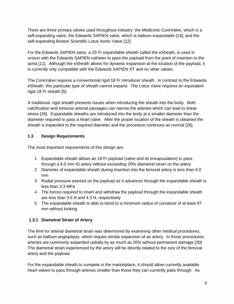
There are three primary valves used throughout industry: the Medtronic CoreValve, which is a
self-expanding valve; the Edwards SAPIEN valve, which is balloon-expandable [14]; and the
self-expanding Boston Scientific Lotus Aortic Valve [12].
For the Edwards SAPIEN valve, a 20 Fr expandable sheath called the eSheath, is used in
unison with the Edwards SAPIEN catheter to pass the payload from the point of insertion to the
aorta [11]. Although the eSheath allows for dynamic expansion at the location of the payload, it
is currently only compatible with the Edwards SAPIEN XT and no other valves.
The CoreValve requires a conventional rigid 18 Fr introducer sheath. In contrast to the Edwards
eSheath, this particular type of sheath cannot expand. The Lotus Valve requires an equivalent
rigid 18 Fr sheath [5].
A traditional, rigid sheath presents issues when introducing the sheath into the body. Both
calcification and tortuous arterial passages can narrow the arteries which can lead to shear
stress [26]. Expandable sheaths are introduced into the body at a smaller diameter than the
diameter required to pass a heart valve. After the proper location of the sheath is obtained the
sheath is expanded to the required diameter and the procedure continues as normal [26].
1.3 Design Requirements
The most important requirements of this design are:
1 Expandable sheath allows an 18 Fr payload (valve and its encapsulation) to pass
through a 6.0 mm ID artery without exceeding 20% diametral strain on the artery
2 Diameter of expandable sheath during insertion into the femoral artery is less than 6.0
mm
3 Radial pressure exerted on the payload as it advances through the expandable sheath is
less than 3.3 MPa
4 The forces required to insert and withdraw the payload through the expandable sheath
are less than 3.6 N and 4.3 N, respectively
5 The expandable sheath is able to bend to a minimum radius of curvature of at least 97
mm without kinking
1.3.1 Diametral Strain of Artery
The limit for arterial diametral strain was determined by examining other medical procedures,
such as balloon angioplasty, which require similar expansion of an artery. In those procedures,
arteries are commonly expanded radially by as much as 20% without permanent damage [30].
The diametral strain experienced by the artery will be directly related to the size of the femoral
artery and the payload.
For the expandable sheath to compete in the marketplace, it should allow currently available
heart valves to pass through arteries smaller than those they can currently pass through. As
4
such, the expandable sheath must allow an 18 Fr payload to pass through an artery 6.0 mm or
smaller. Because the human anatomy can vary significantly from person to person, there was
no way to ensure the expandable sheath is compatible with all persons. 6.0 mm was chosen as
the artery size to design for at the recommendation of the project sponsor and advisor, Mr.
Douglas Post.
1.3.2 Diameter of Expandable Sheath during Insertion
Complications relating to arterial access occur in up to 40% of all TAVI procedures [14], and can
be quite severe, including arterial dissection and avulsion. Limiting these occurrences is of
paramount importance to the survivability of the procedure. A major cause of these
complications is shear force between medical device and the arterial wall [31]. The unexpanded
outer diameter of the expandable sheath at the time of insertion into the femoral artery must be
less than the inner diameter of the artery to mitigate this shear force [31].
1.3.3 Radial Pressure Exerted on Payload
Minimizing radial pressure exerted on the payload is important mainly because too much radial
pressure could cause damage to the payload, but also because the amount of force required to
pass the payload through the expandable sheath is proportional to the radial force exerted on
the payload. Acceptable values were determined experimentally by applying an incrementing
radial force to a catheter, which mimicked the payload delivery catheter, and determining the
force required to cause observable deformation.
1.3.4 Force Required to Insert and Withdraw Payload
Minimizing the force required to advance the payload through the sheath is important because
the surgeon performing the procedure needs to be able to maintain tight control over the
payload during the procedure, and this control may be compromised if he or she has to exert
undue force on the delivery catheter. In addition, a high force requirement for advancement of
the payload indicates high shear stress on the payload and potential for excessive abrasion to
the payload’s surface. Acceptable values for this force were estimated experimentally by
advancing a catheter of increasing diameter through a rubber tube of constant diameter until
“reasonable force” could no longer advance the catheter. Research regarding the force
required for removal of sheaths from arteries affirmed that these estimates are reasonable [2].
1.3.5 Minimum Bend Radius without Kinking
Human femoral arteries exhibit some tortuosity, so to gain access to the aorta and allow
passage of the payload, it is necessary that the expandable sheath be able to bend to a
minimum radius of curvature of at least 97 mm without experiencing kinking which would block
passage of a payload. The minimum radius of curvature that the sheath should be able to pass
through without kinking was determined from tortuosity and curvature data for the femoral
arteries of a general population [1].
5
2 Design Description
2.1 Summary of the Design
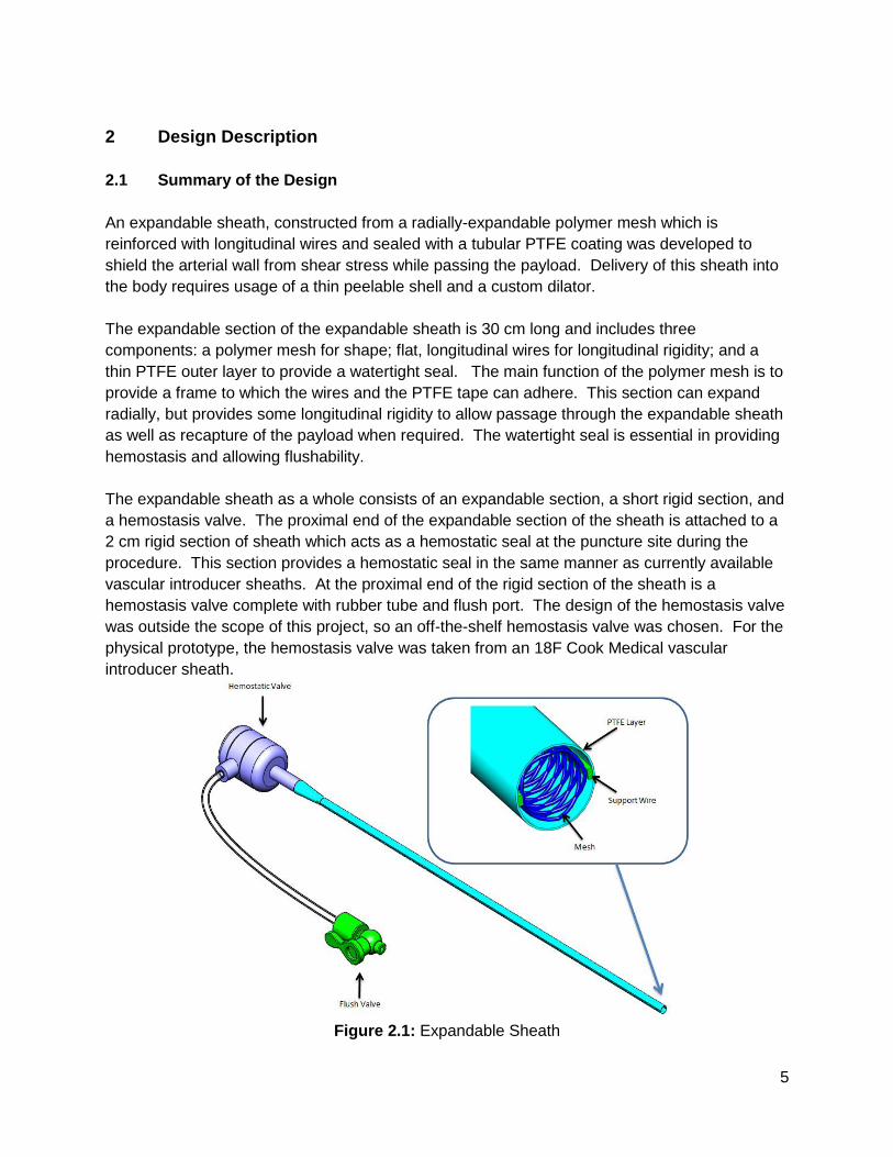
An expandable sheath, constructed from a radially-expandable polymer mesh which is
reinforced with longitudinal wires and sealed with a tubular PTFE coating was developed to
shield the arterial wall from shear stress while passing the payload. Delivery of this sheath into
the body requires usage of a thin peelable shell and a custom dilator.
The expandable section of the expandable sheath is 30 cm long and includes three
components: a polymer mesh for shape; flat, longitudinal wires for longitudinal rigidity; and a
thin PTFE outer layer to provide a watertight seal. The main function of the polymer mesh is to
provide a frame to which the wires and the PTFE tape can adhere. This section can expand
radially, but provides some longitudinal rigidity to allow passage through the expandable sheath
as well as recapture of the payload when required. The watertight seal is essential in providing
hemostasis and allowing flushability.
The expandable sheath as a whole consists of an expandable section, a short rigid section, and
a hemostasis valve. The proximal end of the expandable section of the sheath is attached to a
2 cm rigid section of sheath which acts as a hemostatic seal at the puncture site during the
procedure. This section provides a hemostatic seal in the same manner as currently available
vascular introducer sheaths. At the proximal end of the rigid section of the sheath is a
hemostasis valve complete with rubber tube and flush port. The design of the hemostasis valve
was outside the scope of this project, so an off-the-shelf hemostasis valve was chosen. For the
physical prototype, the hemostasis valve was taken from an 18F Cook Medical vascular
introducer sheath.
Figure 2.1: Expandable Sheath
6
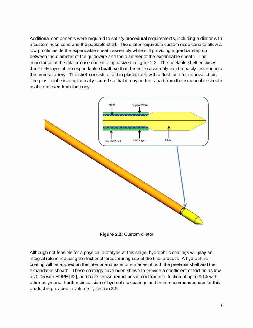
Additional components were required to satisfy procedural requirements, including a dilator with
a custom nose cone and the peelable shell. The dilator requires a custom nose cone to allow a
low profile inside the expandable sheath assembly while still providing a gradual step up
between the diameter of the guidewire and the diameter of the expandable sheath. The
importance of the dilator nose cone is emphasized in figure 2.2. The peelable shell encloses
the PTFE layer of the expandable sheath so that the entire assembly can be easily inserted into
the femoral artery. The shell consists of a thin plastic tube with a flush port for removal of air.
The plastic tube is longitudinally scored so that it may be torn apart from the expandable sheath
as it’s removed from the body.
Figure 2.2: Custom dilator
Although not feasible for a physical prototype at this stage, hydrophilic coatings will play an
integral role in reducing the frictional forces during use of the final product. A hydrophilic
coating will be applied on the interior and exterior surfaces of both the peelable shell and the
expandable sheath. These coatings have been shown to provide a coefficient of friction as low
as 0.05 with HDPE [32], and have shown reductions in coefficient of friction of up to 90% with
other polymers. Further discussion of hydrophilic coatings and their recommended use for this
product is provided in volume II, section 3.5.
7
2.2 Detailed Description
An understanding of the procedural use of the expandable sheath is paramount in
understanding the design. An overview of the use of this device is given in figures 2.3 through
2.9:
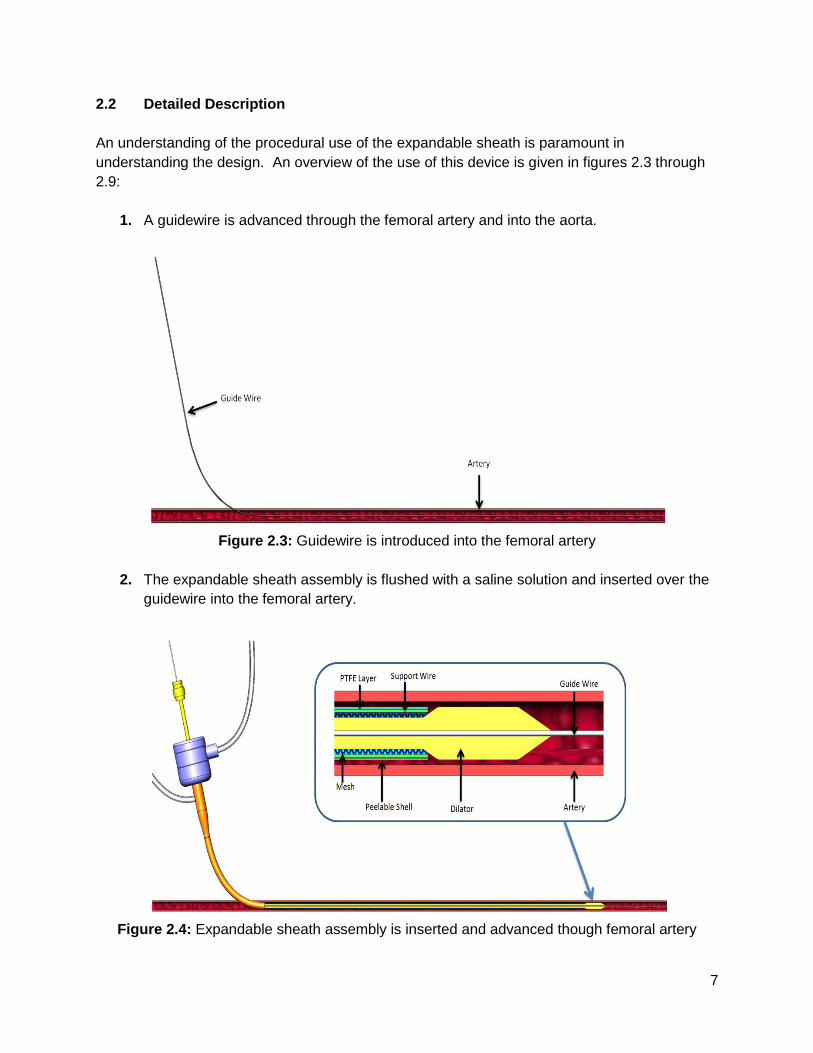
1. A guidewire is advanced through the femoral artery and into the aorta.
Figure 2.3: Guidewire is introduced into the femoral artery
2. The expandable sheath assembly is flushed with a saline solution and inserted over the
guidewire into the femoral artery.
Figure 2.4: Expandable sheath assembly is inserted and advanced though femoral artery
8
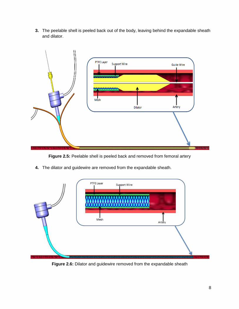
3. The peelable shell is peeled back out of the body, leaving behind the expandable sheath
and dilator.
Figure 2.5: Peelable shell is peeled back and removed from femoral artery
4. The dilator and guidewire are removed from the expandable sheath.
Figure 2.6: Dilator and guidewire removed from the expandable sheath
9
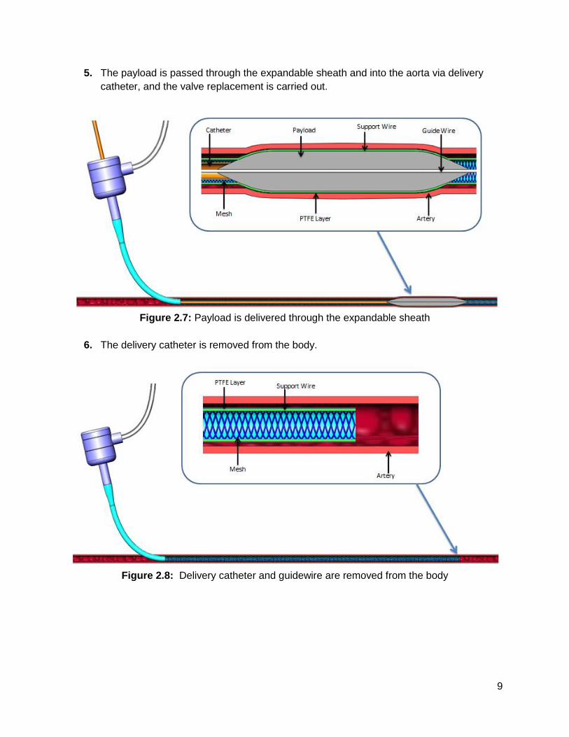
5. The payload is passed through the expandable sheath and into the aorta via delivery
catheter, and the valve replacement is carried out.
Figure 2.7: Payload is delivered through the expandable sheath
6. The delivery catheter is removed from the body.
Figure 2.8: Delivery catheter and guidewire are removed from the body
10
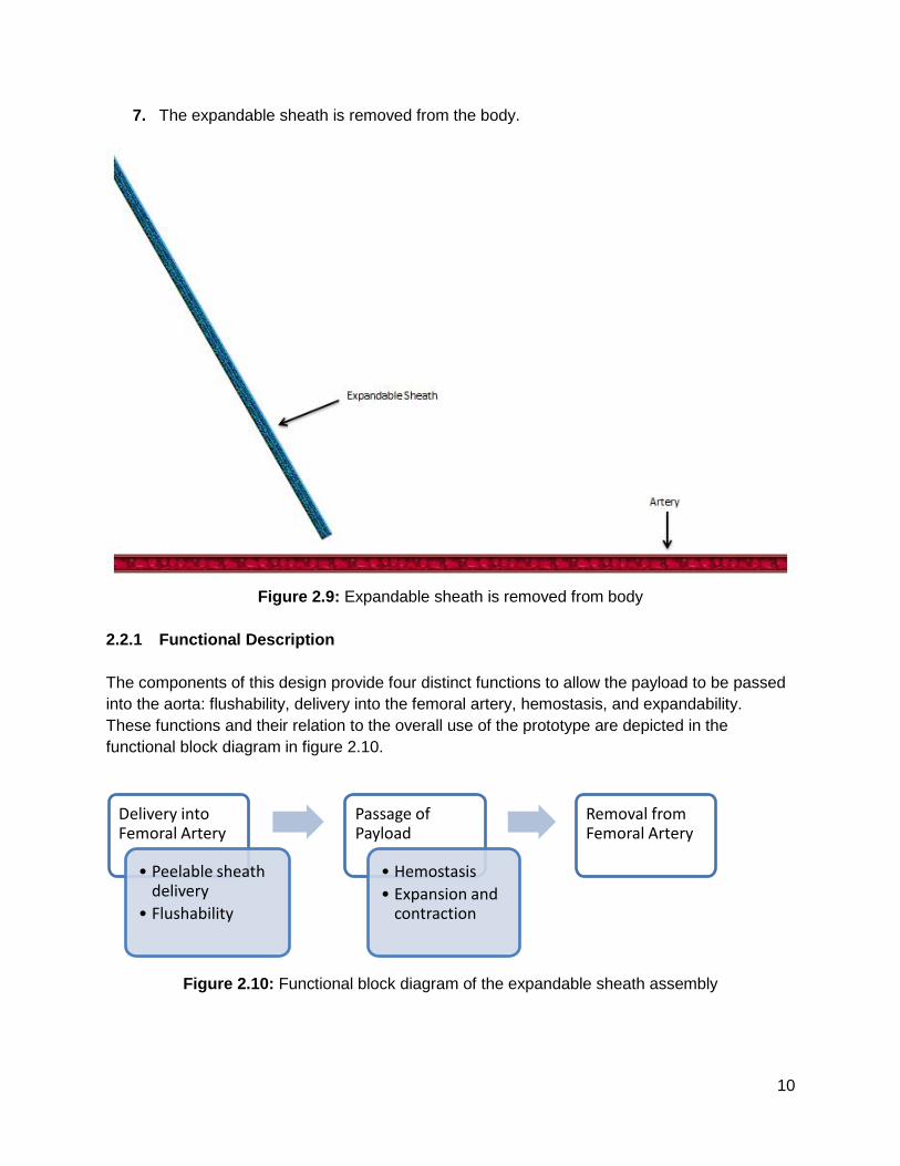
7. The expandable sheath is removed from the body.
Figure 2.9: Expandable sheath is removed from body
2.2.1 Functional Description
The components of this design provide four distinct functions to allow the payload to be passed
into the aorta: flushability, delivery into the femoral artery, hemostasis, and expandability.
These functions and their relation to the overall use of the prototype are depicted in the
functional block diagram in figure 2.10.
Figure 2.10: Functional block diagram of the expandable sheath assembly
Delivery into Femoral Artery
• Peelable sheath delivery
• Flushability
Passage of Payload
• Hemostasis
• Expansion and contraction
Removal from Femoral Artery
11
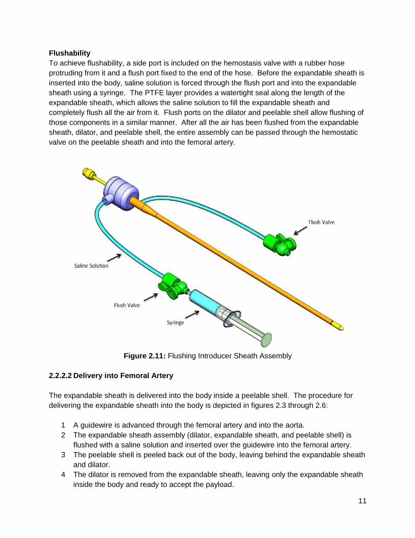
Flushability
To achieve flushability, a side port is included on the hemostasis valve with a rubber hose
protruding from it and a flush port fixed to the end of the hose. Before the expandable sheath is
inserted into the body, saline solution is forced through the flush port and into the expandable
sheath using a syringe. The PTFE layer provides a watertight seal along the length of the
expandable sheath, which allows the saline solution to fill the expandable sheath and
completely flush all the air from it. Flush ports on the dilator and peelable shell allow flushing of
those components in a similar manner. After all the air has been flushed from the expandable
sheath, dilator, and peelable shell, the entire assembly can be passed through the hemostatic
valve on the peelable sheath and into the femoral artery.
Figure 2.11: Flushing Introducer Sheath Assembly
2.2.2.2 Delivery into Femoral Artery
The expandable sheath is delivered into the body inside a peelable shell. The procedure for
delivering the expandable sheath into the body is depicted in figures 2.3 through 2.6:
1 A guidewire is advanced through the femoral artery and into the aorta.
2 The expandable sheath assembly (dilator, expandable sheath, and peelable shell) is
flushed with a saline solution and inserted over the guidewire into the femoral artery.
3 The peelable shell is peeled back out of the body, leaving behind the expandable sheath
and dilator.
4 The dilator is removed from the expandable sheath, leaving only the expandable sheath
inside the body and ready to accept the payload.
12
The peelable shell is a thin walled plastic tube with a flush port on one end. The tube is scored
longitudinally so that it can be torn away from the expandable sheath as it’s removed from the
body. Its inner diameter is just large enough so that the expandable sheath and dilator can be
loaded inside with enough clearance to allow the shell to be peeled off. A hydrophilic coating at
the interface between the peelable shell and the expandable sheath reduces the force required
to peel the shell out of the body.
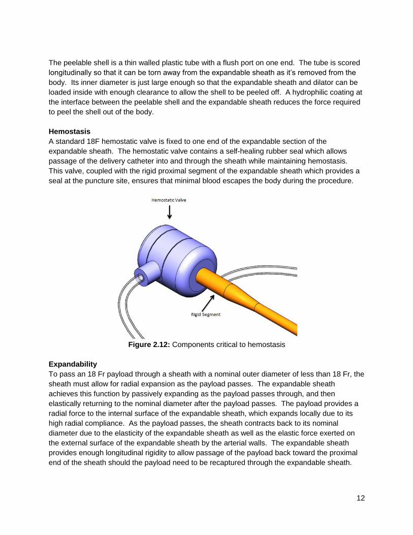
Hemostasis
A standard 18F hemostatic valve is fixed to one end of the expandable section of the
expandable sheath. The hemostatic valve contains a self-healing rubber seal which allows
passage of the delivery catheter into and through the sheath while maintaining hemostasis.
This valve, coupled with the rigid proximal segment of the expandable sheath which provides a
seal at the puncture site, ensures that minimal blood escapes the body during the procedure.
Figure 2.12: Components critical to hemostasis
Expandability
To pass an 18 Fr payload through a sheath with a nominal outer diameter of less than 18 Fr, the
sheath must allow for radial expansion as the payload passes. The expandable sheath
achieves this function by passively expanding as the payload passes through, and then
elastically returning to the nominal diameter after the payload passes. The payload provides a
radial force to the internal surface of the expandable sheath, which expands locally due to its
high radial compliance. As the payload passes, the sheath contracts back to its nominal
diameter due to the elasticity of the expandable sheath as well as the elastic force exerted on
the external surface of the expandable sheath by the arterial walls. The expandable sheath
provides enough longitudinal rigidity to allow passage of the payload back toward the proximal
end of the sheath should the payload need to be recaptured through the expandable sheath.
13
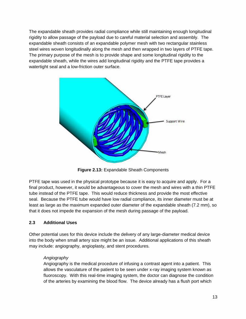
The expandable sheath provides radial compliance while still maintaining enough longitudinal
rigidity to allow passage of the payload due to careful material selection and assembly. The
expandable sheath consists of an expandable polymer mesh with two rectangular stainless
steel wires woven longitudinally along the mesh and then wrapped in two layers of PTFE tape.
The primary purpose of the mesh is to provide shape and some longitudinal rigidity to the
expandable sheath, while the wires add longitudinal rigidity and the PTFE tape provides a
watertight seal and a low-friction outer surface.
Figure 2.13: Expandable Sheath Components
PTFE tape was used in the physical prototype because it is easy to acquire and apply. For a
final product, however, it would be advantageous to cover the mesh and wires with a thin PTFE
tube instead of the PTFE tape. This would reduce thickness and provide the most effective
seal. Because the PTFE tube would have low radial compliance, its inner diameter must be at
least as large as the maximum expanded outer diameter of the expandable sheath (7.2 mm), so
that it does not impede the expansion of the mesh during passage of the payload.
2.3 Additional Uses
Other potential uses for this device include the delivery of any large-diameter medical device
into the body when small artery size might be an issue. Additional applications of this sheath
may include: angiography, angioplasty, and stent procedures.
Angiography
Angiography is the medical procedure of infusing a contrast agent into a patient. This
allows the vasculature of the patient to be seen under x-ray imaging system known as
fluoroscopy. With this real-time imaging system, the doctor can diagnose the condition
of the arteries by examining the blood flow. The device already has a flush port which
14
will allow the doctor to inject a contrast agent if desired.
Angioplasty
This is the practice of widening stenosed arteries to allow better blood flow. An
unexpanded balloon catheter would be passed through the sheath and advanced to the
stenosed region of the artery. The balloon is then inflated to permanently expand the
narrowed arterial walls.
Stenting
Another method for preventing flow-restriction is by applying stents to narrowed artery
walls. Stents provide structural support for stenosed arteries. The stent would be
advanced via a balloon catheter through the sheath until it reaches the stenosed region.
Similar to angioplasty, the balloon is expanded thus applying the stent to the arterial
walls.
3 Evaluation
3.1 Evaluation Plan
The primary portion of this design to be thoroughly validated was the expandable section of the
sheath. As such, the top design requirements to be validated were:
1 Does not induce more than 20% diametral strain on artery during passage of payload
2 Has an outer diameter of less than 6 mm prior to insertion into femoral artery
3 Does not exceed 3.3 MPa radial pressure exerted on payload
4 Does not exceed 3.6 N of push force for insertion of the payload or 4.3 N of pull force for
withdrawal of the payload
5 Able to bend to a radius of less than 97 mm without kinking
Each of these specifications was evaluated either analytically or by performing experiments on
the physical prototype.
During passage of payload, the sheath will be in constant contact with the the arterial wall, so
the expandable sheath outer diameter and artery inner diameter would be equivalent while the
payload is in the expandable sheath. The expandable sheath OD during payload passage was
measured, and the resulting diametral strain on the artery was then calculated.
The outer diameter of the sheath prior to insertion into the femoral artery was determined by
measuring the outer diameter of the sheath at various points along the length of the sheath after
it had been prepared for insertion into the femoral artery.
There are two sources of radial pressure exerted on the payload; one is the elastic reaction
force from the expansion of the artery and the other is the elastic reaction force from the
expansion of the sheath. The radial pressure exerted on the payload was determined by
15
summing these two sources. The radial pressure from the arterial expansion was determined
by hand-calculation and ANSYS finite element modeling, while the radial pressure from the
expansion of the sheath was established by characterizing the pressure versus diameter curve
of the sheath.
The push force required for insertion of the payload and the pull force required for withdrawal of
the payload were determined by measuring the peak force required to pass a mock payload
through the expandable section of the sheath, first by pushing it through the sheath and then
retrieving it through the sheath. In vivo insertion and withdrawal forces were predicted from the
experimental results.
The allowable bend radius without inducing kinking was determined by passing the sheath
through a clear, rubber tube, which was bent to a specified bend radius, and ensuring that no
observable kinking of the sheath had occurred.
3.2 Evaluation Results
3.2.1 Strain Induced on Artery During Passage of Payload
While it is safe to subject arteries to some radial expansion, there is a diametral strain limit after
which point permanent damage is incurred. For this type of procedure, diametral strains of up
to 20% have been proven safe [30][31]. The amount of radial expansion experienced by the
artery is directly related to the dimensions of the expandable sheath, so it is crucial to control
the thickness characteristics of the sheath as these directly affect the arterial strain. To
maintain a diametral strain on the artery of less than 20%, the maximum outer diameter of the
expandable sheath during passage of the payload had to be less than 7.2 mm, which allowed
for a maximum wall thickness of 0.6 mm for the expandable sheath. The measurements of the
sheath during payload passage are included in table 3.1.
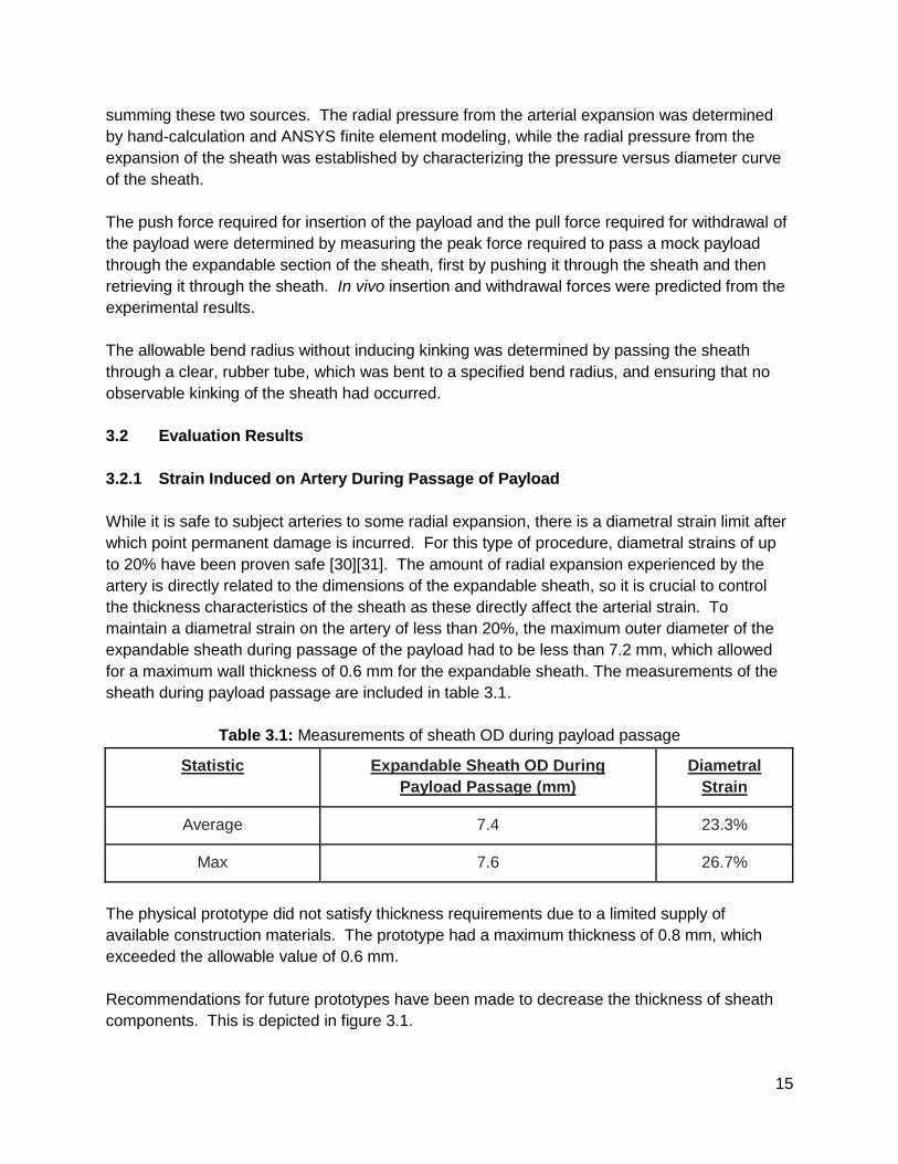
Table 3.1: Measurements of sheath OD during payload passage
Statistic Expandable Sheath OD During
Payload Passage (mm)
Diametral
Strain
Average 7.4 23.3%
Max 7.6 26.7%
The physical prototype did not satisfy thickness requirements due to a limited supply of
available construction materials. The prototype had a maximum thickness of 0.8 mm, which
exceeded the allowable value of 0.6 mm.
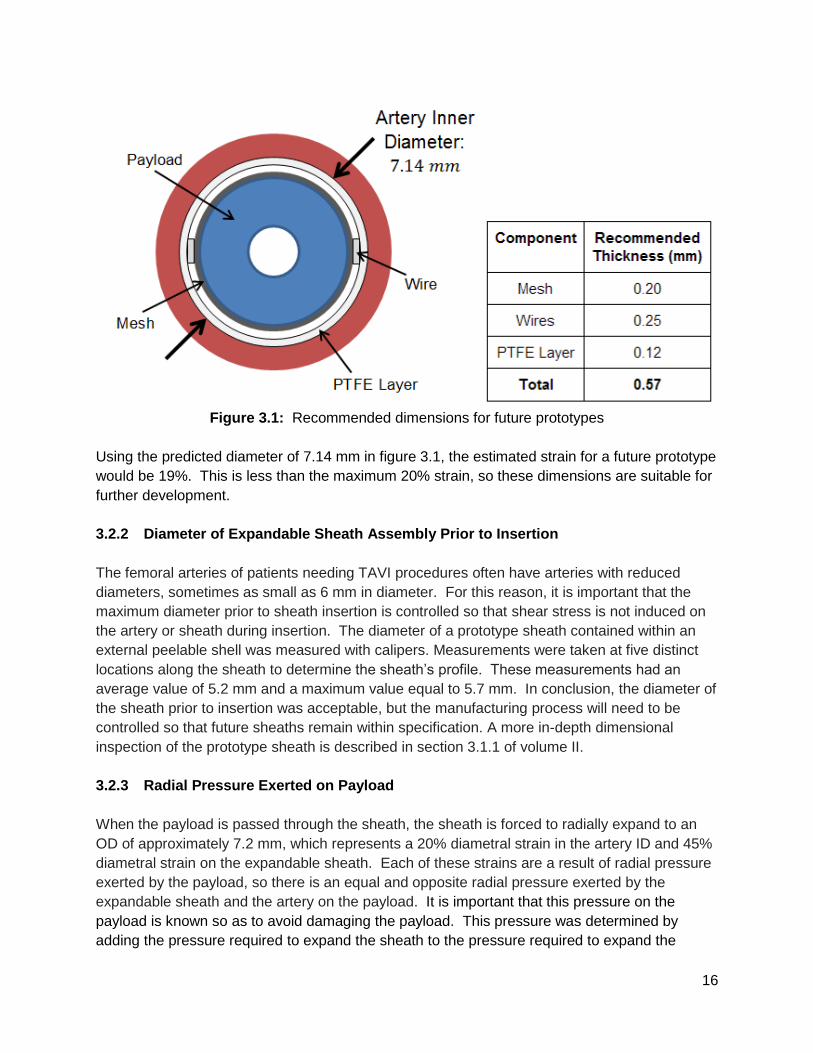
Recommendations for future prototypes have been made to decrease the thickness of sheath
components. This is depicted in figure 3.1.
16
Figure 3.1: Recommended dimensions for future prototypes
Using the predicted diameter of 7.14 mm in figure 3.1, the estimated strain for a future prototype
would be 19%. This is less than the maximum 20% strain, so these dimensions are suitable for
further development.
3.2.2 Diameter of Expandable Sheath Assembly Prior to Insertion
The femoral arteries of patients needing TAVI procedures often have arteries with reduced
diameters, sometimes as small as 6 mm in diameter. For this reason, it is important that the
maximum diameter prior to sheath insertion is controlled so that shear stress is not induced on
the artery or sheath during insertion. The diameter of a prototype sheath contained within an
external peelable shell was measured with calipers. Measurements were taken at five distinct
locations along the sheath to determine the sheath’s profile. These measurements had an
average value of 5.2 mm and a maximum value equal to 5.7 mm. In conclusion, the diameter of
the sheath prior to insertion was acceptable, but the manufacturing process will need to be
controlled so that future sheaths remain within specification. A more in-depth dimensional
inspection of the prototype sheath is described in section 3.1.1 of volume II.
3.2.3 Radial Pressure Exerted on Payload
When the payload is passed through the sheath, the sheath is forced to radially expand to an
OD of approximately 7.2 mm, which represents a 20% diametral strain in the artery ID and 45%
diametral strain on the expandable sheath. Each of these strains are a result of radial pressure
exerted by the payload, so there is an equal and opposite radial pressure exerted by the
expandable sheath and the artery on the payload. It is important that this pressure on the
payload is known so as to avoid damaging the payload. This pressure was determined by
adding the pressure required to expand the sheath to the pressure required to expand the
17
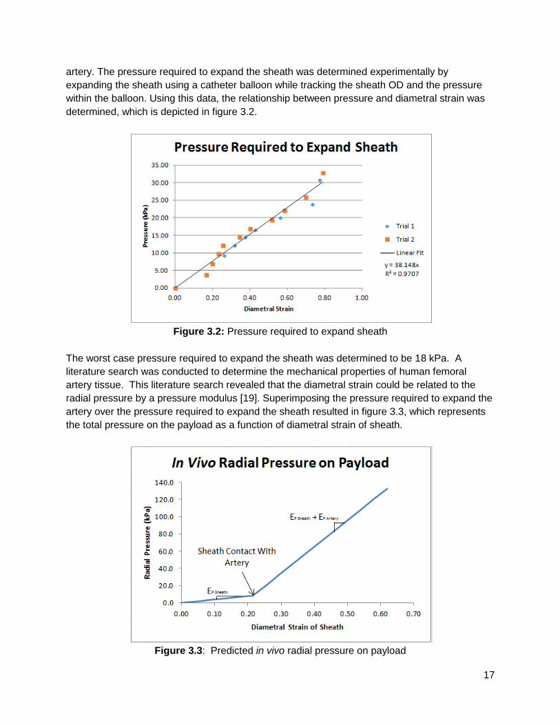
artery. The pressure required to expand the sheath was determined experimentally by
expanding the sheath using a catheter balloon while tracking the sheath OD and the pressure
within the balloon. Using this data, the relationship between pressure and diametral strain was
determined, which is depicted in figure 3.2.
Figure 3.2: Pressure required to expand sheath
The worst case pressure required to expand the sheath was determined to be 18 kPa. A
literature search was conducted to determine the mechanical properties of human femoral
artery tissue. This literature search revealed that the diametral strain could be related to the
radial pressure by a pressure modulus [19]. Superimposing the pressure required to expand the
artery over the pressure required to expand the sheath resulted in figure 3.3, which represents
the total pressure on the payload as a function of diametral strain of sheath.
Figure 3.3: Predicted in vivo radial pressure on payload
18
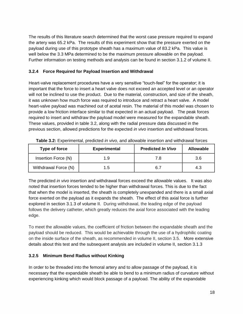
The results of this literature search determined that the worst case pressure required to expand
the artery was 65.2 kPa. The results of this experiment show that the pressure exerted on the
payload during use of this prototype sheath has a maximum value of 83.2 kPa. This value is
well below the 3.3 MPa determined to be the maximum pressure allowable on the payload.
Further information on testing methods and analysis can be found in section 3.1.2 of volume II.
3.2.4 Force Required for Payload Insertion and Withdrawal
Heart-valve replacement procedures have a very sensitive “touch-feel” for the operator; it is
important that the force to insert a heart valve does not exceed an accepted level or an operator
will not be inclined to use the product. Due to the material, construction, and size of the sheath,
it was unknown how much force was required to introduce and retract a heart valve. A model
heart-valve payload was machined out of acetal resin. The material of this model was chosen to
provide a low friction interface similar to that expected in an actual payload. The peak forces
required to insert and withdraw the payload model were measured for the expandable sheath.
These values, provided in table 3.2, along with the radial pressure data discussed in the
previous section, allowed predictions for the expected in vivo insertion and withdrawal forces.
Table 3.2: Experimental, predicted in vivo, and allowable insertion and withdrawal forces
Type of force Experimental Predicted In Vivo Allowable
Insertion Force (N) 1.9 7.8 3.6
Withdrawal Force (N) 1.5 6.7 4.3
The predicted in vivo insertion and withdrawal forces exceed the allowable values. It was also
noted that insertion forces tended to be higher than withdrawal forces. This is due to the fact
that when the model is inserted, the sheath is completely unexpanded and there is a small axial
force exerted on the payload as it expands the sheath. The effect of this axial force is further
explored in section 3.1.3 of volume II. During withdrawal, the leading edge of the payload
follows the delivery catheter, which greatly reduces the axial force associated with the leading
edge.
To meet the allowable values, the coefficient of friction between the expandable sheath and the
payload should be reduced. This would be achievable through the use of a hydrophilic coating
on the inside surface of the sheath, as recommended in volume II, section 3.5. More extensive
details about this test and the subsequent analysis are included in volume II, section 3.1.3
3.2.5 Minimum Bend Radius without Kinking
In order to be threaded into the femoral artery and to allow passage of the payload, it is
necessary that the expandable sheath be able to bend to a minimum radius of curvature without
experiencing kinking which would block passage of a payload. The ability of the expandable
19
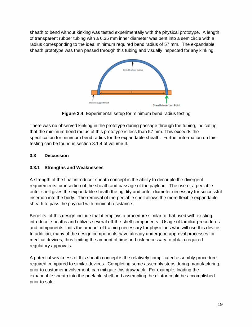
sheath to bend without kinking was tested experimentally with the physical prototype. A length
of transparent rubber tubing with a 6.35 mm inner diameter was bent into a semicircle with a
radius corresponding to the ideal minimum required bend radius of 57 mm. The expandable
sheath prototype was then passed through this tubing and visually inspected for any kinking.
Figure 3.4: Experimental setup for minimum bend radius testing
There was no observed kinking in the prototype during passage through the tubing, indicating
that the minimum bend radius of this prototype is less than 57 mm. This exceeds the
specification for minimum bend radius for the expandable sheath. Further information on this
testing can be found in section 3.1.4 of volume II.
3.3 Discussion
3.3.1 Strengths and Weaknesses
A strength of the final introducer sheath concept is the ability to decouple the divergent
requirements for insertion of the sheath and passage of the payload. The use of a peelable
outer shell gives the expandable sheath the rigidity and outer diameter necessary for successful
insertion into the body. The removal of the peelable shell allows the more flexible expandable
sheath to pass the payload with minimal resistance.
Benefits of this design include that it employs a procedure similar to that used with existing
introducer sheaths and utilizes several off-the-shelf components. Usage of familiar procedures
and components limits the amount of training necessary for physicians who will use this device.
In addition, many of the design components have already undergone approval processes for
medical devices, thus limiting the amount of time and risk necessary to obtain required
regulatory approvals.
A potential weakness of this sheath concept is the relatively complicated assembly procedure
required compared to similar devices. Completing some assembly steps during manufacturing,
prior to customer involvement, can mitigate this drawback. For example, loading the
expandable sheath into the peelable shell and assembling the dilator could be accomplished
prior to sale.
20
Although this device has a relatively standard usage procedure, it does include supplemental
steps to flush and remove the peelable shell. The additional time required for the insertion
procedure would be moderated with appropriate training of users.
The preliminary prototype device has other limitations that will need to be addressed in future
iterations. The estimated in vivo forces required to insert and withdraw the payload exceed
those stated in the product design specifications. The use of a hydrophilic coating on the inside
surface of the expandable sheath would significantly reduce the coefficient of friction between
the payload and sheath. The prototype has a wall thickness greater than that required to pass
an 18 Fr payload while remaining within arterial expansion limits. Use of thinner PTFE extrusion
and mesh materials in future prototypes is recommended to rectify this problem. Due to
manufacturing and schedule limitations, a fully functional peelable shell was not realized during
this design project. This is a crucial component of the proposed device and will be a requisite
addition to future prototypes.
3.3.2 Next Steps
Due to the time and budget constraints on this project, a proof-of-concept prototype was
developed, but it was not possible to construct a ready-for-use product. The prototype
developed was able to undergo tests to determine the validity of the design and justify further
investment. The major component of the prototype which needs to be further developed in
future prototypes is the peelable shell. Leading candidates for this peelable sheath include a
scored, heat-shrink tubing or a scored polymer thin-walled tube with a stepped diameter to
accommodate the rigid section of the expandable sheath. These options will be evaluated in
the next round of prototyping and design testing. Further recommendations for future
prototypes are given in volume II.
With the recommendations and proof-of-concept, the next step for this project is to seek out
investors or potential suitors to handle further development of the product. Were a suitor
identified, that entity would evaluate the recommendations for the next stage of prototype. They
would identify which lubricious coatings would be incorporated, as well as develop a
manufacturing plan suitable for mass production of the final product. In addition, the potential
manufacturer would need to develop packaging for the device and determine an appropriate
sterilization process.