Embed Size (px)
Citation preview
DISTRIBUTED CO-SIMULATION PROTOCOL (DCP)
DOCUMENT STATUS: MODELICA ASSOCIATION STANDARD
DOCUMENT TYPE: SPECIFICATION DOCUMENT
VERSION: 1.0.0
DATE: MARCH 4, 2019
Distributed Co-Simulation Protocol Specification Version 1.0
2 / 112
Executive summary
This document defines the Distributed Co-Simulation Protocol (DCP), version 1.0. The DCP is a
platform and communication medium independent standard for the integration of models or real-
time systems into simulation environments. DCP development was driven by the idea to make
simulation based work flows more efficient, reduce integration effort and simplify related pro-
cesses, and improve the integration of real-time systems. This standard is supported by OEMs,
suppliers, tool providers, universities and research organizations.
Standardisation
This specification is developed and maintained by the newly founded Modelica Association Pro-
ject (MAP) Distributed Co-Simulation Protocol (DCP). For further information see:
www.dcp-standard.org
www.modelica.org
To get in touch with MAP DCP, contact us at [email protected].
History
Version Date Remarks
1.0 2019-03-04 First version of the Distributed Co-Simulation Protocol.
Distributed Co-Simulation Protocol Specification Version 1.0
3 / 112
Contributors
Specification document editor:
Martin Krammer, Kompetenzzentrum - Das Virtuelle Fahrzeug Forschungsgesellschaft mbH
The “DCP Specification 1.0-Release Candidate 2” document was created in scope of the
ITEA3 project ACOSAR from 09/2015 to 08/2018. Essential parts thereof were contributed by the
ACOSAR Core Team. This development group was headed by Martin Krammer (Kompetenzzent-
rum - Das Virtuelle Fahrzeug Forschungsgesellschaft mbH). Its members in alphabetical order
were:
Khaled Alekeish, ESI-ITI Gmbh
Nicolas Amringer, dSPACE GmbH
Martin Benedikt, Kompetenzzentrum - Das Virtuelle Fahrzeug Forschungsgesellschaft mbH
Torsten Blochwitz, ESI-ITI GmbH
Isidro Corral, Robert Bosch GmbH
Micha Damm-Norwig, KS.MicroNova GmbH
Christian Kater, Leibniz Universität Hannover
Serge Klein, RWTH Aachen University
Martin Krammer, Kompetenzzentrum - Das Virtuelle Fahrzeug Forschungsgesellschaft mbH
Stefan Materne, TWT GmbH
Natarajan Nagarajan, ETAS GmbH
Roberto Ruvalcaba, TWT GmbH
Viktor Schreiber, University of Ilmenau
Klaus Schuch, AVL List GmbH
Tommy Sparber, Spath Micro Electronic Design GmbH
Andreas Thuy, ETAS GmbH
The “DCP Specification 1.0-Release Candidate 4” document was developed after the ACO-
SAR project, from 09/2018 to 02/2019. Essential parts thereof were contributed by the following
people, in alphabetical order:
Khaled Alekeish, ESI-ITI GmbH
Torsten Blochwitz, ESI-ITI GmbH
Isidro Corral, Robert Bosch GmbH
Micha Damm-Norwig, KS.MicroNova GmbH
Christian Kater, Leibniz Universität Hannover
Martin Krammer, Kompetenzzentrum - Das Virtuelle Fahrzeug Forschungsgesellschaft mbH
Stefan Materne, TWT GmbH
Klaus Schuch, AVL List GmbH
Stefan Walter, dSPACE GmbH
The following people contributed through reviews and comments, in alphabetical order:
Leo Gall, LTX Simulation GmbH
Andreas Junghanns, QTronic GmbH
Pierre Mai, PMSF IT Consulting
Distributed Co-Simulation Protocol Specification Version 1.0
4 / 112
License of this Document
This DCP specification document is issued under Creative Commons Attribution-ShareAlike 4.0
International (CC BY-SA 4.0).
Copyright © 2016-2018 ACOSAR consortium, 2018-2019 Modelica Association Project (MAP)
Distributed Co-Simulation Protocol (DCP).
This is a human-readable summary of (and not a substitute for) the license. The legal license
text and disclaimer is available at:
https://creativecommons.org/licenses/by-sa/4.0/legalcode
You are free to:
Share — copy and redistribute the material in any medium or format
Adapt — remix, transform, and build upon the material
for any purpose, even commercially.
Under the following terms:
Attribution — You must give appropriate credit, provide a link to the license, and indicate if
changes were made. You may do so in any reasonable manner, but not in any way that suggests
the licensor endorses you or your use.
ShareAlike — If you remix, transform, or build upon the material, you must distribute your con-
tributions under the same license as the original.
No additional restrictions — You may not apply legal terms or technological measures that
legally restrict others from doing anything the license permits.
Notices:
You do not have to comply with the license for elements of the material in the public domain or
where your use is permitted by an applicable exception or limitation.
No warranties are given. The license may not give you all of the permissions necessary for your
intended use. For example, other rights such as publicity, privacy, or moral rights may limit how
you use the material.
Distributed Co-Simulation Protocol Specification Version 1.0
5 / 112
Contents
1 Overview .................................................................................................................................................................................. 7 2 Properties and Guiding Ideas................................................................................................................................................... 8 3 Protocol Specification ............................................................................................................................................................ 10
3.1 Basic Definitions ........................................................................................................................................................... 10 3.1.1 Keywords ................................................................................................................................................................. 10 3.1.2 Version Descriptor ................................................................................................................................................... 10 3.1.3 DCP Slave ................................................................................................................................................................. 10 3.1.4 DCP File .................................................................................................................................................................... 10 3.1.5 Master-Slave Architecture ....................................................................................................................................... 11 3.1.6 State Machine .......................................................................................................................................................... 11 3.1.7 Protocol Data Units .................................................................................................................................................. 11 3.1.8 Number Representation .......................................................................................................................................... 11 3.1.9 Indices ...................................................................................................................................................................... 11 3.1.10 Data Types ............................................................................................................................................................... 11 3.1.11 Byte Order ................................................................................................................................................................ 12 3.1.12 Data Type Encoding ................................................................................................................................................. 12 3.1.13 Timing ...................................................................................................................................................................... 14 3.1.14 Notion of Time ......................................................................................................................................................... 14 3.1.15 Operating Modes ..................................................................................................................................................... 14 3.1.16 Time Resolution ....................................................................................................................................................... 15 3.1.17 Communication Step Size ........................................................................................................................................ 15 3.1.18 Variables .................................................................................................................................................................. 15 3.1.19 Dependencies .......................................................................................................................................................... 19 3.1.20 Data Type Conversions ............................................................................................................................................ 19 3.1.21 Native and Non-Native DCP Specification ................................................................................................................ 19 3.1.22 Transport Protocol Numbering ................................................................................................................................ 19 3.1.23 Logging ..................................................................................................................................................................... 20
3.2 State Machine Definitions ............................................................................................................................................ 20 3.2.1 General .................................................................................................................................................................... 20 3.2.2 Description ............................................................................................................................................................... 20 3.2.3 Superstates .............................................................................................................................................................. 22 3.2.4 States ....................................................................................................................................................................... 23 3.2.5 Transitions ............................................................................................................................................................... 29
3.3 PDU Definitions ............................................................................................................................................................ 36 3.3.1 General .................................................................................................................................................................... 36 3.3.2 Structuring ............................................................................................................................................................... 36 3.3.3 PDU Fields ................................................................................................................................................................ 37 3.3.4 PDU Type Identifier Range Distribution ................................................................................................................... 40 3.3.5 Generic PDU Structure ............................................................................................................................................. 40 3.3.6 Allowed PDUs per State ........................................................................................................................................... 42 3.3.7 PDU Definitions ........................................................................................................................................................ 43
3.4 Protocol ........................................................................................................................................................................ 52 3.4.1 Sequence Identifier .................................................................................................................................................. 52 3.4.2 Configuration Request Pattern ................................................................................................................................ 52 3.4.3 State Transition Pattern ........................................................................................................................................... 52 3.4.4 State Reporting ........................................................................................................................................................ 53 3.4.5 Data Exchange.......................................................................................................................................................... 54 3.4.6 Scope........................................................................................................................................................................ 54 3.4.7 PDU Validity ............................................................................................................................................................. 54 3.4.8 Error Reporting ........................................................................................................................................................ 62 3.4.9 Heartbeat ................................................................................................................................................................. 62 3.4.10 Error Handling .......................................................................................................................................................... 63 3.4.11 Unintended Behaviour ............................................................................................................................................. 64
4 Transport Protocols ............................................................................................................................................................... 65 4.1 General ......................................................................................................................................................................... 65 4.2 Internet Protocol (IPv4) Based Transport Protocols ..................................................................................................... 65
4.2.1 General .................................................................................................................................................................... 65 4.2.2 User Datagram Protocol (UDP/IPv4) ........................................................................................................................ 67 4.2.3 Transmission Control Protocol (TCP/IPv4) ............................................................................................................... 67
Distributed Co-Simulation Protocol Specification Version 1.0
6 / 112
4.3 Bluetooth Radio Frequency Communication (RFCOMM) ............................................................................................. 67 4.3.1 General .................................................................................................................................................................... 67 4.3.2 Transport Protocol Specific Fields ............................................................................................................................ 67 4.3.3 Network Information ............................................................................................................................................... 67 4.3.4 Port information ...................................................................................................................................................... 68 4.3.5 PDUs in RFCOMM stream ........................................................................................................................................ 69
4.4 Universal Serial Bus (USB) ............................................................................................................................................ 69 4.4.1 USB Version.............................................................................................................................................................. 69 4.4.2 General .................................................................................................................................................................... 69 4.4.3 Transport Protocol Specific PDU Fields .................................................................................................................... 69 4.4.4 Descriptors ............................................................................................................................................................... 69 4.4.5 Network Information ............................................................................................................................................... 71 4.4.6 DAT_input_output forwarding................................................................................................................................. 72
4.5 CAN Bus Communication Systems ................................................................................................................................ 72 4.5.1 Procedure................................................................................................................................................................. 72 4.5.2 DCP over CAN ........................................................................................................................................................... 72 4.5.3 Definition of KMatrix................................................................................................................................................ 73 4.5.4 Definition of the Scenario Configuration ................................................................................................................. 77
5 DCP Slave Description ............................................................................................................................................................ 78 5.1 General ......................................................................................................................................................................... 78 5.2 Use of Assertions and Constraints ................................................................................................................................ 78 5.3 Data Type Definitions ................................................................................................................................................... 79 5.4 Definition of dcpSlaveDescription Element .................................................................................................................. 80 5.5 Definition of OpMode Element .................................................................................................................................... 82 5.6 Definition of UnitDefinitions Element .......................................................................................................................... 83 5.7 Definition of TypeDefinitions Element ......................................................................................................................... 85
5.7.1 General .................................................................................................................................................................... 85 5.7.2 Definition of Data Types and Attributes .................................................................................................................. 85
5.8 Definition of VendorAnnotations Element ................................................................................................................... 87 5.9 Definition of TimeRes Element ..................................................................................................................................... 87 5.10 Definition of Heartbeat Element .................................................................................................................................. 88 5.11 Definition of TransportProtocols Element .................................................................................................................... 88
5.11.1 General .................................................................................................................................................................... 88 5.11.2 IPv4 Type .................................................................................................................................................................. 89 5.11.3 UDP/IPv4 .................................................................................................................................................................. 90 5.11.4 CAN .......................................................................................................................................................................... 90 5.11.5 USB ........................................................................................................................................................................... 90 5.11.6 Bluetooth ................................................................................................................................................................. 91 5.11.7 TCP/IPv4 ................................................................................................................................................................... 91
5.12 Definition of CapabilityFlags Element........................................................................................................................... 92 5.13 Definition of Variables Element .................................................................................................................................... 92
5.13.1 Definition of Variable Element ................................................................................................................................. 92 5.13.2 Definition of Variable Element Attributes................................................................................................................ 93 5.13.3 Definition of Variable Data Types and Attributes .................................................................................................... 94 5.13.4 Definition of Output Element Attributes ................................................................................................................. 96 5.13.5 Definition of Output Dependencies ......................................................................................................................... 96 5.13.6 Definition of Multi-Dimensional Data Types ............................................................................................................ 97
5.14 Definition of Log Element ............................................................................................................................................. 98 6 Abbreviations....................................................................................................................................................................... 100 7 Literature ............................................................................................................................................................................. 101 8 Glossary ............................................................................................................................................................................... 102 9 Acknowledgments ............................................................................................................................................................... 103 10 Appendix .............................................................................................................................................................................. 104
A. Key Words to Indicate Requirement Levels................................................................................................................ 104 B. Default DCP Slave Integration .................................................................................................................................... 105 C. Example: Encoding of Variables ................................................................................................................................. 106 D. Example: Data Exchange ............................................................................................................................................ 110 E. Recovery Procedure ................................................................................................................................................... 111 F. General Guideline ....................................................................................................................................................... 112
Distributed Co-Simulation Protocol Specification Version 1.0
7 / 112
1 Overview
Virtual system development is getting more and more important in a plenitude of industrial do-
mains to reduce development times, stranded costs and time-to-market. Co-simulation is a par-
ticularly promising approach for interoperable and modular development. The Functional Mock-
up Interface (FMI) defines a standardized specification for the integration of simulation models,
tools and solvers. However, the coupling and integration of real-time systems into simulation
environments (especially of distributed hardware-in-the-loop systems and simulations) still re-
quires enormous effort.
The Distributed Co-Simulation Protocol (DCP) was developed in scope of the ACOSAR (Advanced
Co-Simulation Open Systems Architecture) project. The DCP specifies a data model, a finite state
machine, a set of protocol data units and a communication protocol. It is intended for the inte-
gration of real-time and/or non-real-time systems. It features a master-slave principle. Further-
more, it is defined independently of the underlying transport protocol and distinguishes between
native and non-native DCP specifications. With this approach, support for additional transport
protocols may be added in the future. The DCP specification also includes a default integration
methodology.
The DCP specification document at hand can lead to a modular, considerably more flexible, as
well as shorter system development process. The DCP is suitable for application in numerous
industrial domains. Furthermore, it has the potential to enable new business models.
Distributed Co-Simulation Protocol Specification Version 1.0
8 / 112
2 Properties and Guiding Ideas
In this section, properties are listed, and some principles are defined that guided the design of
the DCP. Six central aspects drive the development: interoperability, integration, compatibility,
communication, performance, and economy.
• Interoperability: The DCP defines a communication protocol intended for the exchange of
simulation related information and data. It enables the interoperability of systems from
different providers. This principle homogenizes the situation exposed when having a het-
erogeneous landscape of tools, protocols, and interfaces commonly found in today’s work
environments. It further facilitates the deployment of co-simulation approaches across
different computers, sites, and companies.
• Integration: The DCP enables the integration of distributed real-time systems and/or non-
real-time systems into one common co-simulation scenario.
The DCP operation follows a master-slave architecture. This type of architecture is benefi-
cial because it ensures the integration of multiple DCP slaves into a common co-
simulation scenario. This principle supports co-simulation of mixed systems, e.g. hard-
ware setups and digital models. The DCP master-slave approach facilitates the addition
and/or removal of single components without the need to stop any DCP slave. Conse-
quently, one can switch between digital models and real hardware setups, and therefore
accelerate the development process.
Furthermore, a default integration methodology is provided. It demonstrates the interplay
of different parts of the DCP specification. Furthermore, it also demonstrates the role of
components that are not part of this DCP specification.
• Compatibility: The DCP is defined in a way such that it supports the integration of FMI
based systems within DCP slaves. This applies to FMI for Model Exchange as well as FMI
for Co-Simulation. The DCP state machine is designed that it matches operations defined
in the state machine of the FMI. Furthermore, the DCP slave description file is aligned to
the model description file of the FMI. The data types defined in the DCP slave description
file may also be converted to FMI compatible data types. This principle supports FMI-
based simulation models, considering the fact that FMI is one of the most common co-
simulation standards today.
Whereas the FMI represents an application programming interface (API), the DCP repre-
sents a communication protocol. Therefore, it becomes possible to integrate various kinds
of systems. The DCP specification is suitable for a broad range of computing platforms. It
may be implemented on hardware as well as in software. Typical examples are middle-
ware, runtime environments, (virtualized) operating systems, electronic control units,
FPGAs, and many more.
• Communication: The DCP enables simulation data exchange by a variety of communica-
tion systems and transport protocols. The DCP specification refrains from further specifi-
cation of the communication medium. This attribute underscores the underlying design
principle that the choice of the communication medium must be as convenient as possible
for the end-user. DCP abstracts from the most common communication systems. As of
today, supported communication systems and transport protocols include UDP/IPv4, Blue-
tooth, USB, and CAN.
Modern system development processes require the exchange of many different data
types. The DCP specification supports the transmission of data type primitives, vectors,
binary data, and strings. Finally, the DCP specification offers a dedicated safe-state. It
may be used to provide the possibility to implement mechanisms for protection of opera-
tors and the involved hardware. The safety mechanisms themselves are not inherent to
the DCP specification.
• Performance: Distributed real-time and non-real-time co-simulation requires high per-
formance of data exchange. For that reason, the exchanged simulation data at runtime
does not contain any overhead data, like signal names or value references. The DCP sup-
ports data exchange between slaves via the co-simulation master, as well as direct slave
to slave data exchange. The DCP master is free to define either a number of short data
segments, or all data at once for the exchange of simulation data. This also depends on
the capabilities of the communication medium.
Distributed Co-Simulation Protocol Specification Version 1.0
9 / 112
• Economy: The DCP specification is intended to contribute to the following economic land-
marks. First, it helps to reduce development time. This is achieved by independent de-
sign, development, and test of each individual subsystem. Therefore, the development
process can be parallelized. Only the final integration happens collaboratively. Negotia-
tions between system suppliers and integrators can be kept to a minimum. Second, the
DCP specification is independent of any computing platform, which can decrease compu-
ting costs., Third, a shortened time-to-market can be achieved by efficiently setting up
and running an increased number of test cases. Due to the open manner and free availa-
bility of the DCP specification document, a vivid and active DCP community distributes the
DCP specification document into different application domains. The creation of business
opportunities, especially for smaller companies, also emerges from this community. Final-
ly, mutual support and exchange of experience will drive future development of the DCP.
Distributed Co-Simulation Protocol Specification Version 1.0
10 / 112
3 Protocol Specification
3.1 Basic Definitions
The DCP is a platform-independent protocol which enables communication and data exchange for
co-simulation, between a multitude of different computing platforms, operating systems and
software. This section defines the data types supported by the DCP and their encodings to ena-
ble interoperability between these systems.
3.1.1 Keywords
Unless noted otherwise, the meaning of keywords (must, must not, should, …) as stated in Ap-
pendix A of this document applies.
3.1.2 Version Descriptor
This DCP specification utilizes the following version descriptor numbering scheme. See also sec-
tion 5.4.
• dcpMajorVersion: First level version number. Indicates a major specification release that
is relevant to compliant implementation.
• dcpMinorVersion: Second level version number. Indicates a minor specification release
that is relevant to compliant implementation.
• dcpMaintenanceVersion: Third level version number. Indicates a specification release
that is not relevant to compliant implementation.
3.1.3 DCP Slave
A DCP slave is either a simulation model or a real-time system on a ready-to-run execution plat-
form that is accessible via DCP over a given supported communication medium.
3.1.4 DCP File
All static information related to a DCP slave is stored in an accompanying DCP file (file exten-
sion: .dcp). This file is a zip file. The compression method used for the zip file must be "de-flate".
Any tool exporting or importing such a file must obey the following.
Exporter for DCP files version 1.0
Any tool creating DCP files according to this version of the specification. Its internal structure
must be as follows.
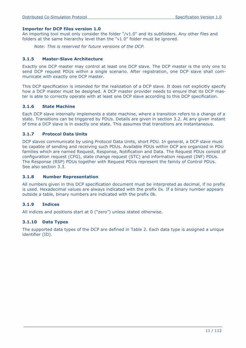
Structure Description
/ Root of the zip file.
Note: It is not allowed to place any other files and
folders at the same hierarchy level than the "v1.0"
folder.
/v1.0 Folder in the root of the zip file.
This is mandatory.
/v1.0/dcpSlaveDescription.dcpx DCP slave description according to this specification. See sec-
tion 5 for details.
This is mandatory.
/v1.0/documentation Directory containing documentation for the DCP slave.
This is optional.
/v1.0/* Other files and folders might be included.
This is optional.
Table 1: Internal structure of DCP file
Distributed Co-Simulation Protocol Specification Version 1.0
11 / 112
Importer for DCP files version 1.0
An importing tool must only consider the folder "/v1.0" and its subfolders. Any other files and
folders at the same hierarchy level than the "v1.0" folder must be ignored.
Note: This is reserved for future versions of the DCP.
3.1.5 Master-Slave Architecture
Exactly one DCP master may control at least one DCP slave. The DCP master is the only one to
send DCP request PDUs within a single scenario. After registration, one DCP slave shall com-
municate with exactly one DCP master.
This DCP specification is intended for the realization of a DCP slave. It does not explicitly specify
how a DCP master must be designed. A DCP master provider needs to ensure that its DCP mas-
ter is able to correctly operate with at least one DCP slave according to this DCP specification.
3.1.6 State Machine
Each DCP slave internally implements a state machine, where a transition refers to a change of a
state. Transitions can be triggered by PDUs. Details are given in section 3.2. At any given instant
of time a DCP slave is in exactly one state. This assumes that transitions are instantaneous.
3.1.7 Protocol Data Units
DCP slaves communicate by using Protocol Data Units, short PDU. In general, a DCP slave must
be capable of sending and receiving such PDUs. Available PDUs within DCP are organized in PDU
families which are named Request, Response, Notification and Data. The Request PDUs consist of
configuration request (CFG), state change request (STC) and information request (INF) PDUs.
The Response (RSP) PDUs together with Request PDUs represent the family of Control PDUs.
See also section 3.3.
3.1.8 Number Representation
All numbers given in this DCP specification document must be interpreted as decimal, if no prefix
is used. Hexadecimal values are always indicated with the prefix 0x. If a binary number appears
outside a table, binary numbers are indicated with the prefix 0b.
3.1.9 Indices
All indices and positions start at 0 (“zero”) unless stated otherwise.
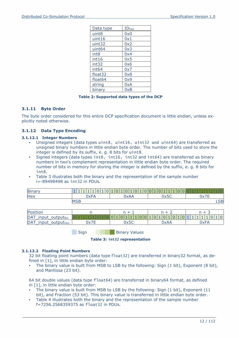
3.1.10 Data Types
The supported data types of the DCP are defined in Table 2. Each data type is assigned a unique
identifier (ID).
Distributed Co-Simulation Protocol Specification Version 1.0
12 / 112
Data type IDhex
uint8 0x0
uint16 0x1
uint32 0x2
uint64 0x3
int8 0x4
int16 0x5
int32 0x6
int64 0x7
float32 0x8
float64 0x9
string 0xA
binary 0xB
Table 2: Supported data types of the DCP
3.1.11 Byte Order
The byte order considered for this entire DCP specification document is little endian, unless ex-
plicitly noted otherwise.
3.1.12 Data Type Encoding
3.1.12.1 Integer Numbers
• Unsigned integers (data types uint8, uint16, uint32 and uint64) are transferred as
unsigned binary numbers in little endian byte order. The number of bits used to store the
integer is defined by its suffix, e. g. 8 bits for uint8.
• Signed integers (data types int8, int16, int32 and int64) are transferred as binary
numbers in two's complement representation in little endian byte order. The required
number of bits in memory for storing the integer is defined by the suffix, e. g. 8 bits for
int8.
• Table 3 illustrates both the binary and the representation of the sample number
i=-89498498 as int32 in PDUs.
Binary 1 1 1 1 1 0 1 0 1 0 1 0 1 0 1 0 0 1 0 1 1 1 0 0 0 1 1 1 1 1 1 0
Hex 0xFA 0xAA 0x5C 0x7E
MSB LSB
Position n n + 1 n + 2 n + 3
DAT_input_outputBin 0 1 1 1 1 1 1 0 0 1 0 1 1 1 0 0 1 0 1 0 1 0 1 0 1 1 1 1 1 0 1 0
DAT_input_outputHex 0x7E 0x5C 0xAA 0xFA
Sign Binary Values
Table 3: int32 representation
3.1.12.2 Floating Point Numbers
32 bit floating point numbers (data type float32) are transferred in binary32 format, as de-
fined in [1], in little endian byte order:
• The binary value is built from MSB to LSB by the following: Sign (1 bit), Exponent (8 bit),
and Mantissa (23 bit).
64 bit double values (data type float64) are transferred in binary64 format, as defined
in [1], in little endian byte order:
• The binary value is built from MSB to LSB by the following: Sign (1 bit), Exponent (11
bit), and Fraction (53 bit). This binary value is transferred in little endian byte order.
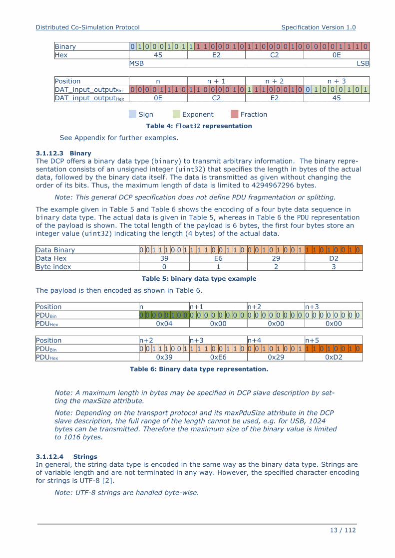
• Table 4 illustrates both the binary and the representation of the sample number
f=7256.2568359375 as float32 in PDUs.
Distributed Co-Simulation Protocol Specification Version 1.0
13 / 112
Binary 0 1 0 0 0 1 0 1 1 1 1 0 0 0 1 0 1 1 0 0 0 0 1 0 0 0 0 0 1 1 1 0
Hex 45 E2 C2 0E
MSB LSB
Position n n + 1 n + 2 n + 3
DAT_input_outputBin 0 0 0 0 1 1 1 0 1 1 0 0 0 0 1 0 1 1 1 0 0 0 1 0 0 1 0 0 0 1 0 1
DAT_input_outputHex 0E C2 E2 45
Sign Exponent Fraction
Table 4: float32 representation
See Appendix for further examples.
3.1.12.3 Binary
The DCP offers a binary data type (binary) to transmit arbitrary information. The binary repre-
sentation consists of an unsigned integer (uint32) that specifies the length in bytes of the actual
data, followed by the binary data itself. The data is transmitted as given without changing the
order of its bits. Thus, the maximum length of data is limited to 4294967296 bytes.
Note: This general DCP specification does not define PDU fragmentation or splitting.
The example given in Table 5 and Table 6 shows the encoding of a four byte data sequence in
binary data type. The actual data is given in Table 5, whereas in Table 6 the PDU representation
of the payload is shown. The total length of the payload is 6 bytes, the first four bytes store an
integer value (uint32) indicating the length (4 bytes) of the actual data.
Data Binary 0 0 1 1 1 0 0 1 1 1 1 0 0 1 1 0 0 0 1 0 1 0 0 1 1 1 0 1 0 0 1 0
Data Hex 39 E6 29 D2
Byte index 0 1 2 3
Table 5: binary data type example
The payload is then encoded as shown in Table 6.
Position n n+1 n+2 n+3
PDUBin 0 0 0 0 0 1 0 0 0 0 0 0 0 0 0 0 0 0 0 0 0 0 0 0 0 0 0 0 0 0 0 0
PDUHex 0x04 0x00 0x00 0x00
Position n+2 n+3 n+4 n+5
PDUBin 0 0 1 1 1 0 0 1 1 1 1 0 0 1 1 0 0 0 1 0 1 0 0 1 1 1 0 1 0 0 1 0
PDUHex 0x39 0xE6 0x29 0xD2
Table 6: Binary data type representation.
Note: A maximum length in bytes may be specified in DCP slave description by set-
ting the maxSize attribute.
Note: Depending on the transport protocol and its maxPduSize attribute in the DCP
slave description, the full range of the length cannot be used, e.g. for USB, 1024
bytes can be transmitted. Therefore the maximum size of the binary value is limited
to 1016 bytes.
3.1.12.4 Strings
In general, the string data type is encoded in the same way as the binary data type. Strings are
of variable length and are not terminated in any way. However, the specified character encoding
for strings is UTF-8 [2].
Note: UTF-8 strings are handled byte-wise.
Distributed Co-Simulation Protocol Specification Version 1.0
14 / 112
Note: A maximum length in bytes may be specified in DCP slave description by set-
ting the maxSize attribute. Also note that the length in bytes does not necessarily
match the number of encoded characters in the string.
Note: Depending on the transport protocol and its maxPduSize attribute in the DCP
slave description, the full range of the length cannot be used, e.g. for USB, 1024
bytes can be transmitted. Therefore the maximum size of the binary value is limited
to 1016 bytes.
Note: These definitions apply to protocol data units (PDUs, as defined in section 3.3)
only.
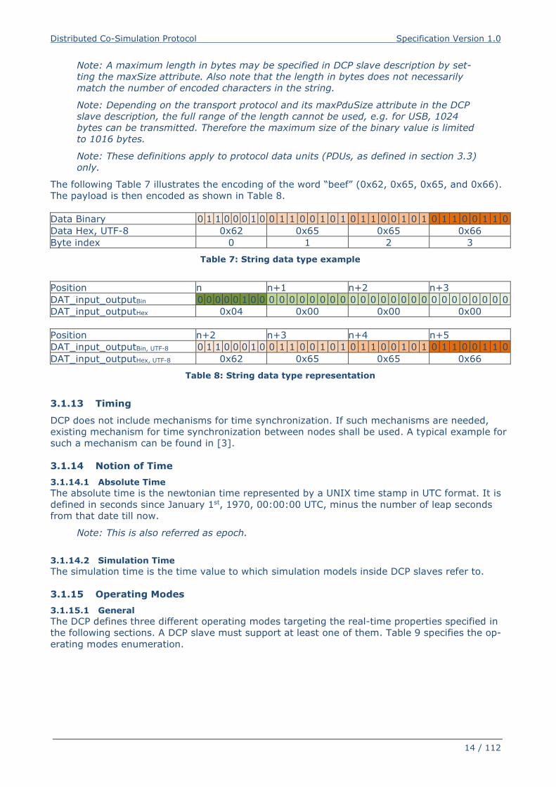
The following Table 7 illustrates the encoding of the word “beef” (0x62, 0x65, 0x65, and 0x66).
The payload is then encoded as shown in Table 8.
Data Binary 0 1 1 0 0 0 1 0 0 1 1 0 0 1 0 1 0 1 1 0 0 1 0 1 0 1 1 0 0 1 1 0
Data Hex, UTF-8 0x62 0x65 0x65 0x66
Byte index 0 1 2 3
Table 7: String data type example
Position n n+1 n+2 n+3
DAT_input_outputBin 0 0 0 0 0 1 0 0 0 0 0 0 0 0 0 0 0 0 0 0 0 0 0 0 0 0 0 0 0 0 0 0
DAT_input_outputHex 0x04 0x00 0x00 0x00
Position n+2 n+3 n+4 n+5
DAT_input_outputBin, UTF-8 0 1 1 0 0 0 1 0 0 1 1 0 0 1 0 1 0 1 1 0 0 1 0 1 0 1 1 0 0 1 1 0
DAT_input_outputHex, UTF-8 0x62 0x65 0x65 0x66
Table 8: String data type representation
3.1.13 Timing
DCP does not include mechanisms for time synchronization. If such mechanisms are needed,
existing mechanism for time synchronization between nodes shall be used. A typical example for
such a mechanism can be found in [3].
3.1.14 Notion of Time
3.1.14.1 Absolute Time
The absolute time is the newtonian time represented by a UNIX time stamp in UTC format. It is
defined in seconds since January 1st, 1970, 00:00:00 UTC, minus the number of leap seconds
from that date till now.
Note: This is also referred as epoch.
3.1.14.2 Simulation Time
The simulation time is the time value to which simulation models inside DCP slaves refer to.
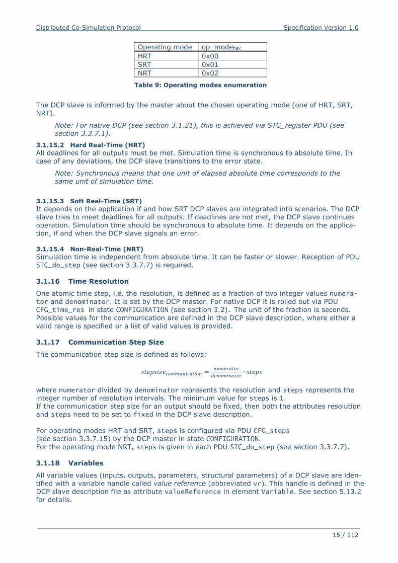
3.1.15 Operating Modes
3.1.15.1 General
The DCP defines three different operating modes targeting the real-time properties specified in
the following sections. A DCP slave must support at least one of them. Table 9 specifies the op-
erating modes enumeration.
Distributed Co-Simulation Protocol Specification Version 1.0
15 / 112
Operating mode op_modehex
HRT 0x00
SRT 0x01
NRT 0x02
Table 9: Operating modes enumeration
The DCP slave is informed by the master about the chosen operating mode (one of HRT, SRT,
NRT).
Note: For native DCP (see section 3.1.21), this is achieved via STC_register PDU (see
section 3.3.7.1).
3.1.15.2 Hard Real-Time (HRT)
All deadlines for all outputs must be met. Simulation time is synchronous to absolute time. In
case of any deviations, the DCP slave transitions to the error state.
Note: Synchronous means that one unit of elapsed absolute time corresponds to the
same unit of simulation time.
3.1.15.3 Soft Real-Time (SRT)
It depends on the application if and how SRT DCP slaves are integrated into scenarios. The DCP
slave tries to meet deadlines for all outputs. If deadlines are not met, the DCP slave continues
operation. Simulation time should be synchronous to absolute time. It depends on the applica-
tion, if and when the DCP slave signals an error.
3.1.15.4 Non-Real-Time (NRT)
Simulation time is independent from absolute time. It can be faster or slower. Reception of PDU
STC_do_step (see section 3.3.7.7) is required.
3.1.16 Time Resolution
One atomic time step, i.e. the resolution, is defined as a fraction of two integer values numera-tor and denominator. It is set by the DCP master. For native DCP it is rolled out via PDU
CFG_time_res in state CONFIGURATION (see section 3.2). The unit of the fraction is seconds.
Possible values for the communication are defined in the DCP slave description, where either a
valid range is specified or a list of valid values is provided.
3.1.17 Communication Step Size
The communication step size is defined as follows:
������������� ���� = ��� ��������� ��� ∙ �����
where numerator divided by denominator represents the resolution and steps represents the
integer number of resolution intervals. The minimum value for steps is 1.
If the communication step size for an output should be fixed, then both the attributes resolution
and steps need to be set to fixed in the DCP slave description.
For operating modes HRT and SRT, steps is configured via PDU CFG_steps
(see section 3.3.7.15) by the DCP master in state CONFIGURATION.
For the operating mode NRT, steps is given in each PDU STC_do_step (see section 3.3.7.7).
3.1.18 Variables
All variable values (inputs, outputs, parameters, structural parameters) of a DCP slave are iden-
tified with a variable handle called value reference (abbreviated vr). This handle is defined in the
DCP slave description file as attribute valueReference in element Variable. See section 5.13.2
for details.
Distributed Co-Simulation Protocol Specification Version 1.0
16 / 112
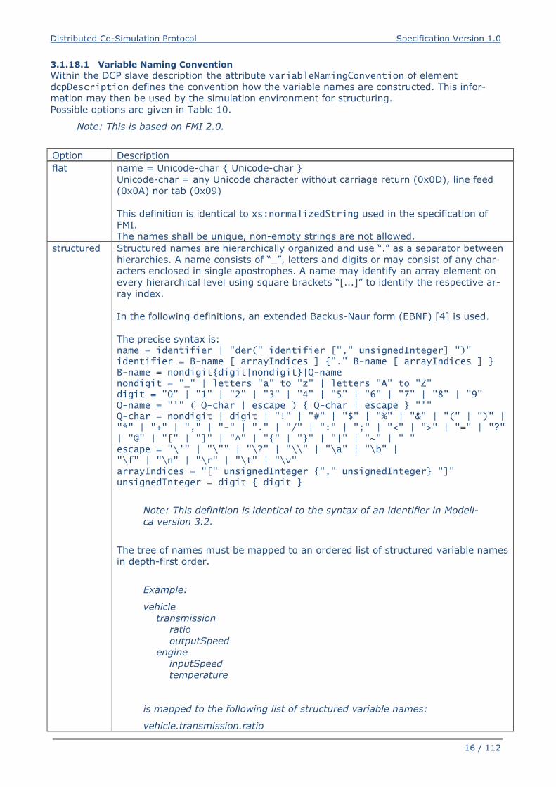
3.1.18.1 Variable Naming Convention
Within the DCP slave description the attribute variableNamingConvention of element
dcpDescription defines the convention how the variable names are constructed. This infor-
mation may then be used by the simulation environment for structuring.
Possible options are given in Table 10.
Note: This is based on FMI 2.0.
Option Description
flat name = Unicode-char { Unicode-char }
Unicode-char = any Unicode character without carriage return (0x0D), line feed
(0x0A) nor tab (0x09)
This definition is identical to xs:normalizedString used in the specification of
FMI.
The names shall be unique, non-empty strings are not allowed.
structured Structured names are hierarchically organized and use “.” as a separator between
hierarchies. A name consists of “_”, letters and digits or may consist of any char-
acters enclosed in single apostrophes. A name may identify an array element on
every hierarchical level using square brackets “[...]” to identify the respective ar-
ray index.
In the following definitions, an extended Backus-Naur form (EBNF) [4] is used.
The precise syntax is: name = identifier | "der(" identifier ["," unsignedInteger] ")" identifier = B-name [ arrayIndices ] {"." B-name [ arrayIndices ] } B-name = nondigit{digit|nondigit}|Q-name nondigit = "_" | letters "a" to "z" | letters "A" to "Z" digit = "0" | "1" | "2" | "3" | "4" | "5" | "6" | "7" | "8" | "9" Q-name = "’" ( Q-char | escape ) { Q-char | escape } "’" Q-char = nondigit | digit | "!" | "#" | "$" | "%" | "&" | "(" | ")" | "*" | "+" | "," | "-" | "." | "/" | ":" | ";" | "<" | ">" | "=" | "?" | "@" | "[" | "]" | "^" | "{" | "}" | "|" | "~" | " " escape = "\’" | "\"" | "\?" | "\\" | "\a" | "\b" | "\f" | "\n" | "\r" | "\t" | "\v" arrayIndices = "[" unsignedInteger {"," unsignedInteger} "]" unsignedInteger = digit { digit }
Note: This definition is identical to the syntax of an identifier in Modeli-
ca version 3.2.
The tree of names must be mapped to an ordered list of structured variable names
in depth-first order.
Example:
vehicle
transmission
ratio
outputSpeed
engine
inputSpeed
temperature
is mapped to the following list of structured variable names:
vehicle.transmission.ratio
Distributed Co-Simulation Protocol Specification Version 1.0
17 / 112
vehicle.transmission.outputSpeed
vehicle.engine.inputSpeed
vehicle.engine.temperature
Note: No further restrictions apply (e.g., no alphabetical sort on same
hierarchical level)
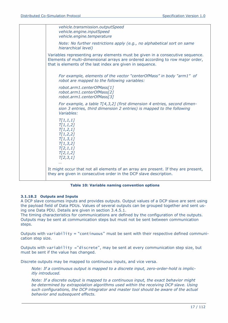
Variables representing array elements must be given in a consecutive sequence.
Elements of multi-dimensional arrays are ordered according to row major order,
that is elements of the last index are given in sequence.
For example, elements of the vector “centerOfMass” in body “arm1” of
robot are mapped to the following variables:
robot.arm1.centerOfMass[1]
robot.arm1.centerOfMass[2]
robot.arm1.centerOfMass[3]
For example, a table T[4,3,2] (first dimension 4 entries, second dimen-
sion 3 entries, third dimension 2 entries) is mapped to the following
Variables:
T[1,1,1]
T[1,1,2]
T[1,2,1]
T[1,2,2]
T[1,3,1]
T[1,3,2]
T[2,1,1]
T[2,1,2]
T[2,3,1]
…
It might occur that not all elements of an array are present. If they are present,
they are given in consecutive order in the DCP slave description.
Table 10: Variable naming convention options
3.1.18.2 Outputs and Inputs
A DCP slave consumes inputs and provides outputs. Output values of a DCP slave are sent using
the payload field of Data PDUs. Values of several outputs can be grouped together and sent us-
ing one Data PDU. Details are given in section 3.4.5.1.
The timing characteristics for communications are defined by the configuration of the outputs.
Outputs may be sent at communication steps but must not be sent between communication
steps.
Outputs with variability = “continuous” must be sent with their respective defined communi-
cation step size.
Outputs with variability =”discrete”, may be sent at every communication step size, but
must be sent if the value has changed.
Discrete outputs may be mapped to continuous inputs, and vice versa.
Note: If a continuous output is mapped to a discrete input, zero-order-hold is implic-
itly introduced.
Note: If a discrete output is mapped to a continuous input, the exact behavior might
be determined by extrapolation algorithms used within the receiving DCP slave. Using
such configurations, the DCP integrator and master tool should be aware of the actual
behavior and subsequent effects.
Distributed Co-Simulation Protocol Specification Version 1.0
18 / 112
3.1.18.3 Parameters
Parameters are used to change properties of a DCP slave. They can be set by the DCP master
only.
For parameters the variability shall be set to either fixed or tunable.
The values of parameters with variability = “fixed” can be set only in state CONFIGURATION (see section 3.2.4.2).
The values of parameters with variability = “tunable” can be set at any time. The received
value of a tunable parameter shall come into effect during the next computational step of a DCP
slave in NRT operating mode. For the operating modes HRT and SRT the values are adopted im-
mediately. Values of several parameters can be grouped together and sent using one Data PDU.
Details are given in section 3.4.5.2.
If a value for a parameter is not set at all, it stays at its start value which is contained in the DCP
slave description.
Note: To ensure that multiple parameters coming into effect simultaneously, they
must be sent at once.
3.1.18.4 Structural Parameters
Structural parameters may be used to indicate variable dimensions. This is used to define e.g.
vectors and matrices.
Structural parameters have a start value and may be modified during simulation time.
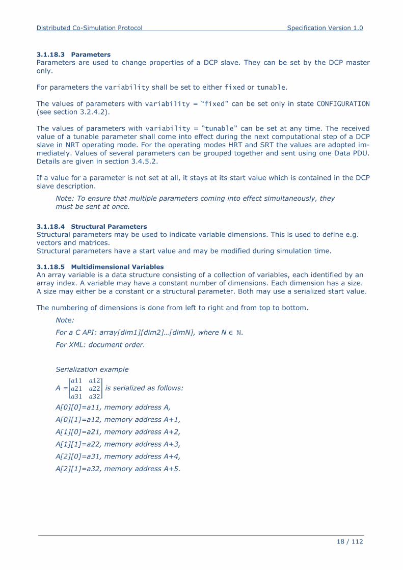
3.1.18.5 Multidimensional Variables
An array variable is a data structure consisting of a collection of variables, each identified by an
array index. A variable may have a constant number of dimensions. Each dimension has a size.
A size may either be a constant or a structural parameter. Both may use a serialized start value.
The numbering of dimensions is done from left to right and from top to bottom.
Note:
For a C API: array[dim1][dim2]…[dimN], where N ∈ ℕ.
For XML: document order.
Serialization example
A =��11 �12�21 �22�31 �32� is serialized as follows:
A[0][0]=a11, memory address A,
A[0][1]=a12, memory address A+1,
A[1][0]=a21, memory address A+2,
A[1][1]=a22, memory address A+3,
A[2][0]=a31, memory address A+4,
A[2][1]=a32, memory address A+5.
Distributed Co-Simulation Protocol Specification Version 1.0
19 / 112
3.1.19 Dependencies
The outputs of a DCP slave might depend on its inputs and parameters.
These dependencies can be described in the DCP slave description (see section 5.13.5). Addi-
tionally, the kind of dependency can be expressed, to allow for an optimized initialization of the
DCP slave.
Note: This information can be utilized to e.g. detect the presence or absence of alge-
braic loops in the configured scenario.
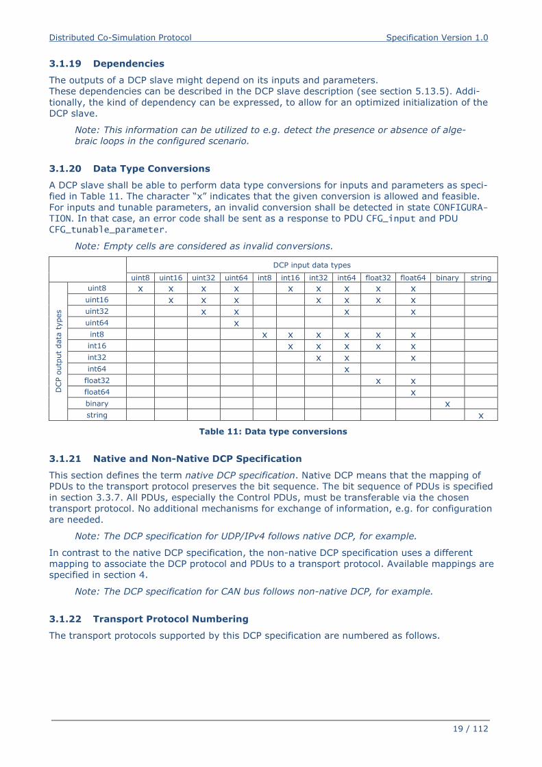
3.1.20 Data Type Conversions
A DCP slave shall be able to perform data type conversions for inputs and parameters as speci-
fied in Table 11. The character “x” indicates that the given conversion is allowed and feasible.
For inputs and tunable parameters, an invalid conversion shall be detected in state CONFIGURA-TION. In that case, an error code shall be sent as a response to PDU CFG_input and PDU
CFG_tunable_parameter.
Note: Empty cells are considered as invalid conversions.
DCP input data types
uint8 uint16 uint32 uint64 int8 int16 int32 int64 float32 float64 binary string
DCP o
utp
ut
data
types
uint8 x x x x x x x x x uint16 x x x x x x x uint32 x x x x uint64 x int8 x x x x x x int16 x x x x x int32 x x x int64 x
float32 x x float64 x binary x string x
Table 11: Data type conversions
3.1.21 Native and Non-Native DCP Specification
This section defines the term native DCP specification. Native DCP means that the mapping of
PDUs to the transport protocol preserves the bit sequence. The bit sequence of PDUs is specified
in section 3.3.7. All PDUs, especially the Control PDUs, must be transferable via the chosen
transport protocol. No additional mechanisms for exchange of information, e.g. for configuration
are needed.
Note: The DCP specification for UDP/IPv4 follows native DCP, for example.
In contrast to the native DCP specification, the non-native DCP specification uses a different
mapping to associate the DCP protocol and PDUs to a transport protocol. Available mappings are
specified in section 4.
Note: The DCP specification for CAN bus follows non-native DCP, for example.
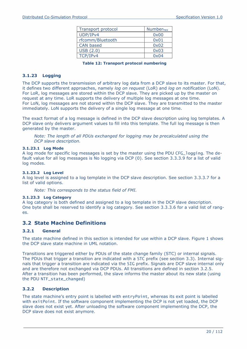
3.1.22 Transport Protocol Numbering
The transport protocols supported by this DCP specification are numbered as follows.
Distributed Co-Simulation Protocol Specification Version 1.0
20 / 112
Transport protocol Numberhex
UDP/IPv4 0x00
rfcomm/Bluetooth 0x01
CAN based 0x02
USB (2.0) 0x03
TCP/IPv4 0x04
Table 12: Transport protocol numbering
3.1.23 Logging
The DCP supports the transmission of arbitrary log data from a DCP slave to its master. For that,
it defines two different approaches, namely log on request (LoR) and log on notification (LoN).
For LoR, log messages are stored within the DCP slave. They are picked up by the master on
request at any time. LoR supports the delivery of multiple log messages at one time.
For LoN, log messages are not stored within the DCP slave. They are transmitted to the master
immediately. LoN supports the delivery of a single log message at one time.
The exact format of a log message is defined in the DCP slave description using log templates. A
DCP slave only delivers argument values to fill into this template. The full log message is then
generated by the master.
Note: The length of all PDUs exchanged for logging may be precalculated using the
DCP slave description.
3.1.23.1 Log Mode
A log mode for specific log messages is set by the master using the PDU CFG_logging. The de-
fault value for all log messages is No logging via DCP (0). See section 3.3.3.9 for a list of valid
log modes.
3.1.23.2 Log Level
A log level is assigned to a log template in the DCP slave description. See section 3.3.3.7 for a
list of valid options.
Note: This corresponds to the status field of FMI.
3.1.23.3 Log Category
A log category is both defined and assigned to a log template in the DCP slave description.
One byte shall be reserved to identify a log category. See section 3.3.3.6 for a valid list of rang-
es.
3.2 State Machine Definitions
3.2.1 General
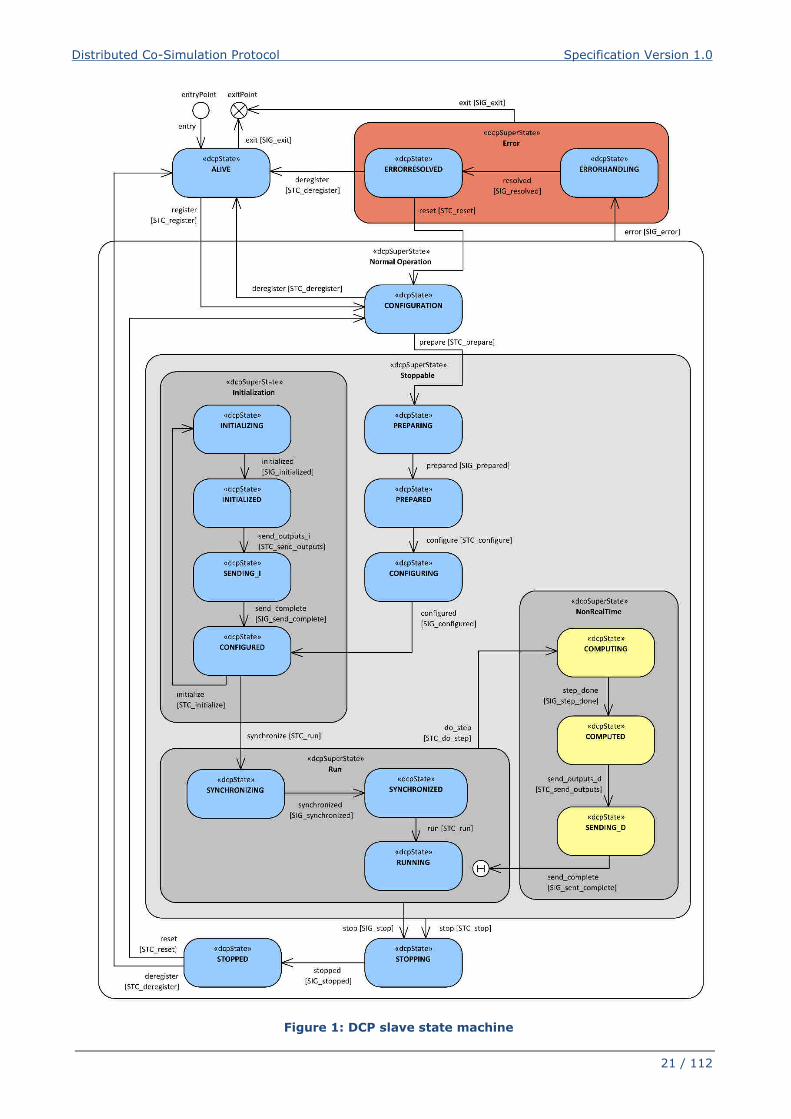
The state machine defined in this section is intended for use within a DCP slave. Figure 1 shows
the DCP slave state machine in UML notation.
Transitions are triggered either by PDUs of the state change family (STC) or internal signals.
The PDUs that trigger a transition are indicated with a STC prefix (see section 3.3). Internal sig-
nals that trigger a transition are indicated via the SIG prefix. Signals are DCP slave internal only
and are therefore not exchanged via DCP PDUs. All transitions are defined in section 3.2.5.
After a transition has been performed, the slave informs the master about its new state (using
the PDU NTF_state_changed)
3.2.2 Description
The state machine’s entry point is labelled with entryPoint, whereas its exit point is labelled
with exitPoint. If the software component implementing the DCP is not yet loaded, the DCP
slave does not exist yet. After unloading the software component implementing the DCP, the
DCP slave does not exist anymore.
Distributed Co-Simulation Protocol Specification Version 1.0
21 / 112
Figure 1: DCP slave state machine
Distributed Co-Simulation Protocol Specification Version 1.0
22 / 112
3.2.3 Superstates
The following sections describe the general behavior of the defined superstates.
3.2.3.1 Normal Operation
The states CONFIGURATION, CONFIGURING, PREPARING, PREPARED, CONFIGURED, INITIALIZING,
INITIALIZED, SENDING_I, RUNNING, COMPUTING, COMPUTED, SENDING_D, STOPPING, and STOPPED belong to a super-state called “Normal Operation”. This superstate assumes that the DCP slave
operates as intended by the DCP slave provider.
3.2.3.2 Error
The states ERRORHANDLING and ERRORRESOLVED belong to a superstate Error. This superstate is
used to handle exceptional conditions that are defined by the DCP slave provider. 3.2.3.3 Initialization
The DCP superstate Initialization is used by a DCP master to align multiple DCP slaves be-
fore running a simulation. The states CONFIGURED, INITIALIZING, INITIALIZED and SEND-ING_I together with their transitions allow the master to apply iterative algorithms to reach a
consistent initial state over all slaves within a scenario. Initialization is independent from abso-
lute time and the chosen operating mode.
3.2.3.4 Run
The states SYNCHRONIZING, SYNCHRONIZED and RUNNING belong to superstate Run. In contrast to
superstate Initialization simulation time can elapse.
For real-time operating modes SRT and HRT simulation time is running and data is exchanged
using the defined step size. For non-real-time operating mode NRT advance of simulation time
and data exchange are handled as described in superstate NonRealTime.
The two states SYNCHRONIZING and RUNNING allow for distinction between a possible initial tran-
sient oscillation phase and the actual simulation experiment. By transitioning to state SYNCHRO-NIZED the slave indicates that it has finished the transient oscillation phase.
Note: For example, when the control loop between an engine test bench and a simu-
lation model is closed, typically initial transient oscillations occur. The actual simula-
tion experiment should only be started after this initial transient oscillation phase.
The initial transient oscillation phase takes place in state SYNCHRONIZING. As soon as
this phase is finished, the slave transitions to state SYNCHRONIZED. As soon as all
slaves are in state SYNCHRONIZED, the master triggers the transition to state RUNNING.
This leads to a defined point in time when the actual simulation experiment starts.
For NRT operating mode, from each state of the superstate Run transition to state COMPUTING of
superstate NonRealTime is possible. On reentry from state SENDING_D to superstate Run the en-
try state is the last state from which the superstate Run was left. This is indicated by the History
element in the state chart (see Figure 1).
3.2.3.5 NonRealTime
The states COMPUTING, COMPUTED, and SENDING_D belong to superstate NonRealTime. The states of NonRealTime are used for triggering calculation, advance of simulation time, and
data exchange.
Note: Consider 1 master and 2 slaves A and B, including slave-to-slave communica-
tion.
Initially all slaves are in state RUNNING.
The master sends PDU STC_do_step to both slaves.
Slave A changes to state COMPUTING, calculates fast, moves on to COMPUTED.
If no state SENDING_D would exist, he would immediately send its outputs to slave B
and changes to state RUNNING.
Distributed Co-Simulation Protocol Specification Version 1.0
23 / 112
Slave B might receive this data before having received the STC_do_step from the
master, due to network delay, latency, etc.
Thus, he would calculate with input data not consistent to current simulation time in-
stance. The state SENDING_D prevents this.
3.2.3.6 Stoppable
The states CONFIGURING, PREPARING, PREPARED, CONFIGURED, INITIALIZING, INITIALIZED,
RUNNING, COMPUTING, COMPUTED, SENDING_I, SENDING_D are grouped in a super-state “Stoppa-
ble”. This means that a slave is allowed to transit to the state Stopping from one of these states. 3.2.4 States
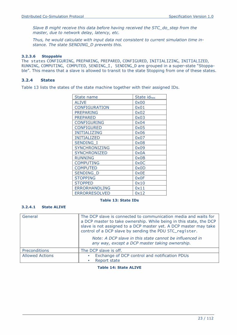
Table 13 lists the states of the state machine together with their assigned IDs.
State name State idhex
ALIVE 0x00
CONFIGURATION 0x01
PREPARING 0x02
PREPARED 0x03
CONFIGURING 0x04
CONFIGURED 0x05
INITIALIZING 0x06
INITIALIZED 0x07
SENDING_I 0x08
SYNCHRONIZING 0x09
SYNCHRONIZED 0x0A
RUNNING 0x0B
COMPUTING 0x0C
COMPUTED 0x0D
SENDING_D 0x0E
STOPPING 0x0F
STOPPED 0x10
ERRORHANDLING 0x11
ERRORRESOLVED 0x12
Table 13: State IDs
3.2.4.1 State ALIVE
General
The DCP slave is connected to communication media and waits for
a DCP master to take ownership. While being in this state, the DCP
slave is not assigned to a DCP master yet. A DCP master may take
control of a DCP slave by sending the PDU STC_register.
Note: A DCP slave in this state cannot be influenced in
any way, except a DCP master taking ownership.
Preconditions The DCP slave is off.
Allowed Actions
• Exchange of DCP control and notification PDUs
• Report state
Table 14: State ALIVE
Distributed Co-Simulation Protocol Specification Version 1.0
24 / 112
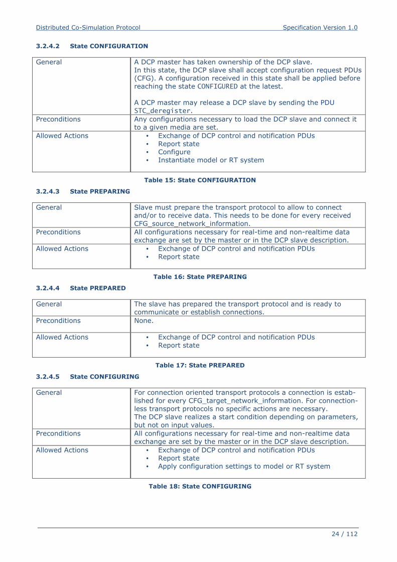
3.2.4.2 State CONFIGURATION
General
A DCP master has taken ownership of the DCP slave.
In this state, the DCP slave shall accept configuration request PDUs
(CFG). A configuration received in this state shall be applied before
reaching the state CONFIGURED at the latest.
A DCP master may release a DCP slave by sending the PDU
STC_deregister.
Preconditions
Any configurations necessary to load the DCP slave and connect it
to a given media are set.
Allowed Actions
• Exchange of DCP control and notification PDUs
• Report state
• Configure
• Instantiate model or RT system
Table 15: State CONFIGURATION
3.2.4.3 State PREPARING
General
Slave must prepare the transport protocol to allow to connect
and/or to receive data. This needs to be done for every received
CFG_source_network_information.
Preconditions
All configurations necessary for real-time and non-realtime data
exchange are set by the master or in the DCP slave description.
Allowed Actions
• Exchange of DCP control and notification PDUs
• Report state
Table 16: State PREPARING
3.2.4.4 State PREPARED
General
The slave has prepared the transport protocol and is ready to
communicate or establish connections.
Preconditions
None.
Allowed Actions
• Exchange of DCP control and notification PDUs
• Report state
Table 17: State PREPARED
3.2.4.5 State CONFIGURING
General
For connection oriented transport protocols a connection is estab-
lished for every CFG_target_network_information. For connection-
less transport protocols no specific actions are necessary.
The DCP slave realizes a start condition depending on parameters,
but not on input values.
Preconditions
All configurations necessary for real-time and non-realtime data
exchange are set by the master or in the DCP slave description.
Allowed Actions
• Exchange of DCP control and notification PDUs
• Report state
• Apply configuration settings to model or RT system
Table 18: State CONFIGURING
Distributed Co-Simulation Protocol Specification Version 1.0
25 / 112
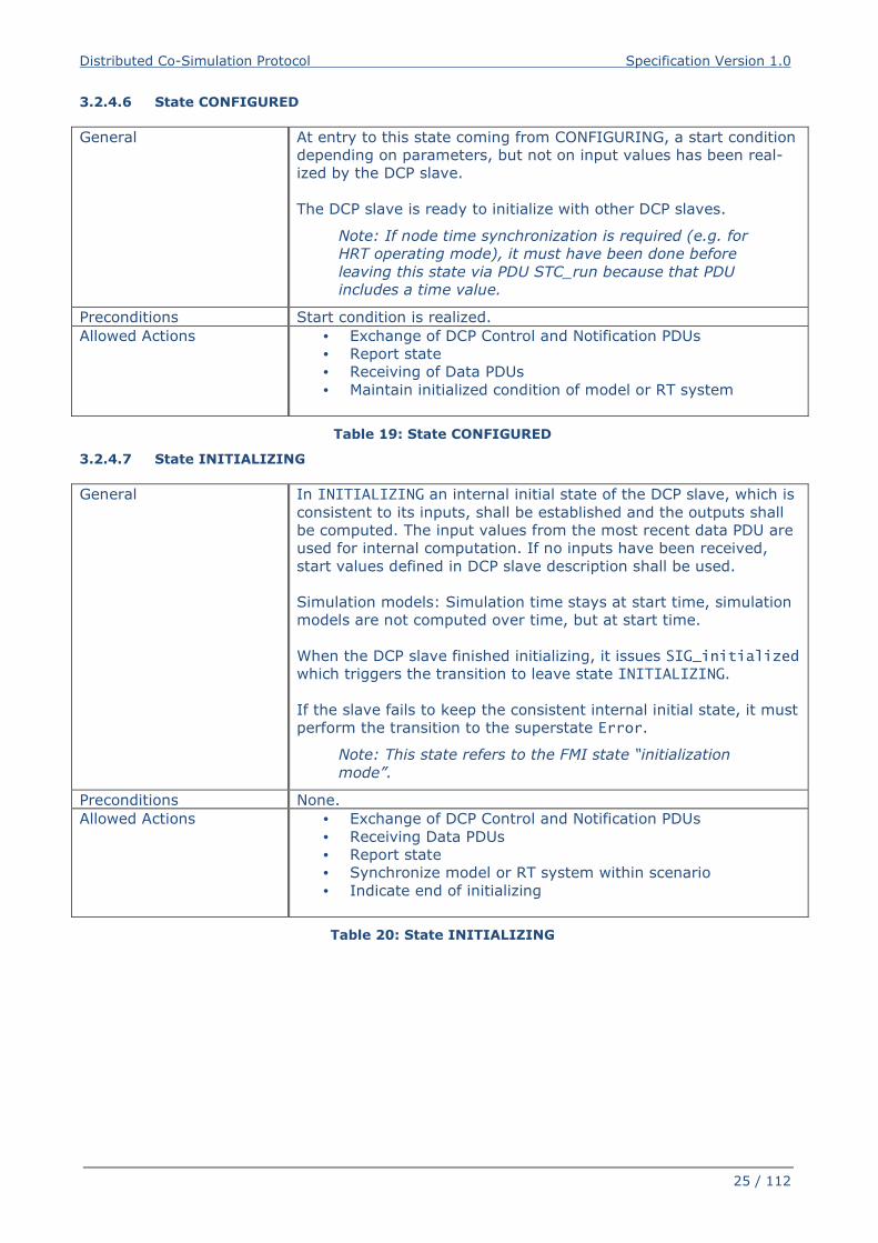
3.2.4.6 State CONFIGURED
General
At entry to this state coming from CONFIGURING, a start condition
depending on parameters, but not on input values has been real-
ized by the DCP slave.
The DCP slave is ready to initialize with other DCP slaves.
Note: If node time synchronization is required (e.g. for
HRT operating mode), it must have been done before
leaving this state via PDU STC_run because that PDU
includes a time value.
Preconditions Start condition is realized.
Allowed Actions
• Exchange of DCP Control and Notification PDUs
• Report state
• Receiving of Data PDUs
• Maintain initialized condition of model or RT system
Table 19: State CONFIGURED
3.2.4.7 State INITIALIZING
General
In INITIALIZING an internal initial state of the DCP slave, which is
consistent to its inputs, shall be established and the outputs shall
be computed. The input values from the most recent data PDU are
used for internal computation. If no inputs have been received,
start values defined in DCP slave description shall be used.
Simulation models: Simulation time stays at start time, simulation
models are not computed over time, but at start time.
When the DCP slave finished initializing, it issues SIG_initialized
which triggers the transition to leave state INITIALIZING.
If the slave fails to keep the consistent internal initial state, it must
perform the transition to the superstate Error.
Note: This state refers to the FMI state “initialization
mode”.
Preconditions None.
Allowed Actions
• Exchange of DCP Control and Notification PDUs
• Receiving Data PDUs
• Report state
• Synchronize model or RT system within scenario
• Indicate end of initializing
Table 20: State INITIALIZING
Distributed Co-Simulation Protocol Specification Version 1.0
26 / 112
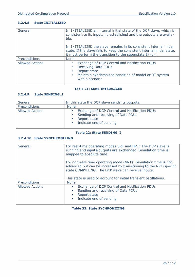
3.2.4.8 State INITIALIZED
General
In INITIALIZED an internal initial state of the DCP slave, which is
consistent to its inputs, is established and the outputs are availa-
ble.
In INITIALIZED the slave remains in its consistent internal initial
state. If the slave fails to keep the consistent internal initial state,
it must perform the transition to the superstate Error.
Preconditions None.
Allowed Actions
• Exchange of DCP Control and Notification PDUs
• Receiving Data PDUs
• Report state
• Maintain synchronized condition of model or RT system
within scenario
Table 21: State INITIALIZED
3.2.4.9 State SENDING_I
General In this state the DCP slave sends its outputs.
Preconditions None
Allowed Actions
• Exchange of DCP Control and Notification PDUs
• Sending and receiving of Data PDUs
• Report state
• Indicate end of sending
Table 22: State SENDING_I
3.2.4.10 State SYNCHRONIZING
General For real-time operating modes SRT and HRT: The DCP slave is
running and inputs/outputs are exchanged. Simulation time is
mapped to absolute time.
For non-real-time operating mode (NRT): Simulation time is not
advanced but can be increased by transitioning to the NRT-specific
state COMPUTING. The DCP slave can receive inputs.
This state is used to account for initial transient oscillations.
Preconditions None
Allowed Actions
• Exchange of DCP Control and Notification PDUs
• Sending and receiving of Data PDUs
• Report state
• Indicate end of sending
Table 23: State SYCHRONIZING
Distributed Co-Simulation Protocol Specification Version 1.0
27 / 112
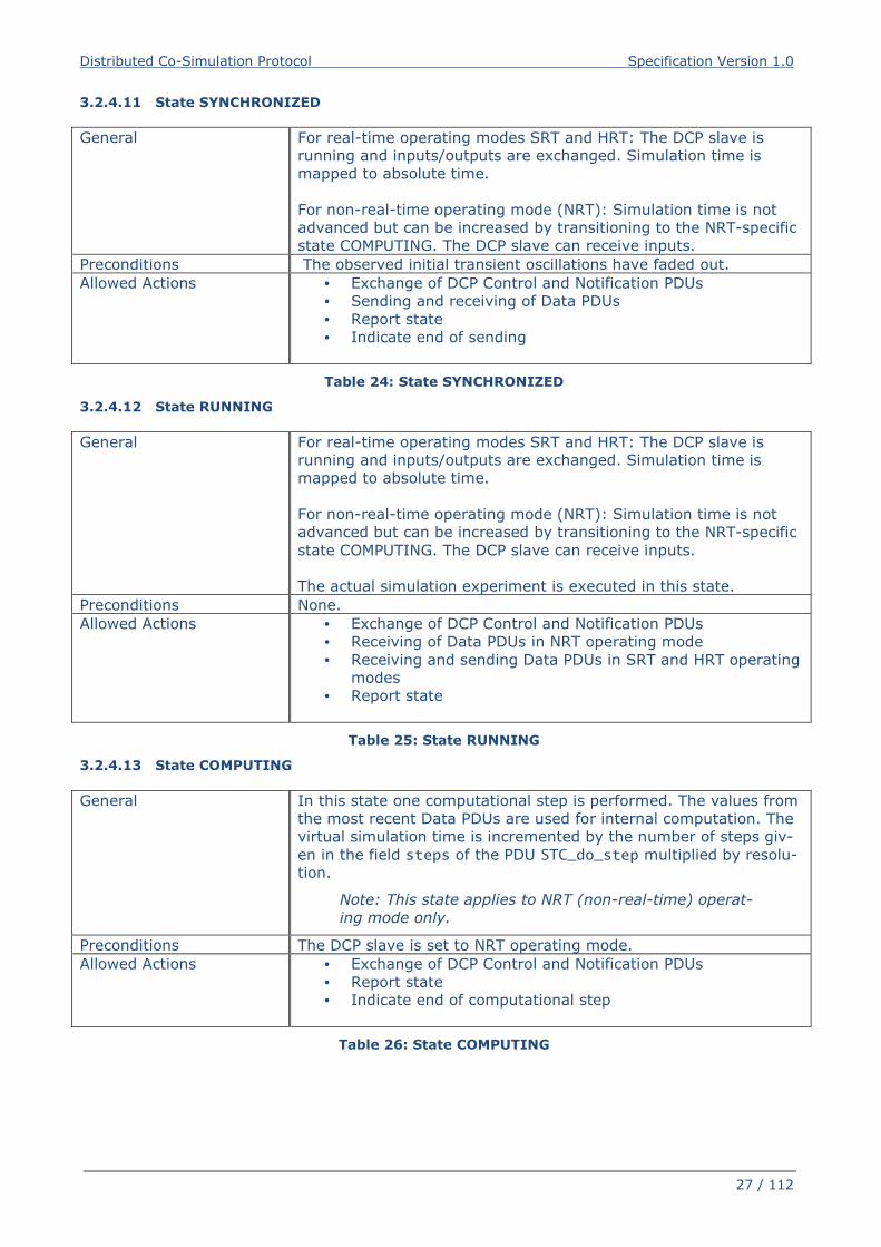
3.2.4.11 State SYNCHRONIZED
General For real-time operating modes SRT and HRT: The DCP slave is
running and inputs/outputs are exchanged. Simulation time is
mapped to absolute time.
For non-real-time operating mode (NRT): Simulation time is not
advanced but can be increased by transitioning to the NRT-specific
state COMPUTING. The DCP slave can receive inputs.
Preconditions The observed initial transient oscillations have faded out.
Allowed Actions
• Exchange of DCP Control and Notification PDUs
• Sending and receiving of Data PDUs
• Report state
• Indicate end of sending
Table 24: State SYNCHRONIZED
3.2.4.12 State RUNNING
General
For real-time operating modes SRT and HRT: The DCP slave is
running and inputs/outputs are exchanged. Simulation time is
mapped to absolute time.
For non-real-time operating mode (NRT): Simulation time is not
advanced but can be increased by transitioning to the NRT-specific
state COMPUTING. The DCP slave can receive inputs.
The actual simulation experiment is executed in this state.
Preconditions None.
Allowed Actions
• Exchange of DCP Control and Notification PDUs
• Receiving of Data PDUs in NRT operating mode
• Receiving and sending Data PDUs in SRT and HRT operating
modes
• Report state
Table 25: State RUNNING
3.2.4.13 State COMPUTING
General
In this state one computational step is performed. The values from
the most recent Data PDUs are used for internal computation. The
virtual simulation time is incremented by the number of steps giv-
en in the field steps of the PDU STC_do_step multiplied by resolu-
tion.
Note: This state applies to NRT (non-real-time) operat-
ing mode only.
Preconditions The DCP slave is set to NRT operating mode.
Allowed Actions
• Exchange of DCP Control and Notification PDUs
• Report state
• Indicate end of computational step
Table 26: State COMPUTING
Distributed Co-Simulation Protocol Specification Version 1.0
28 / 112
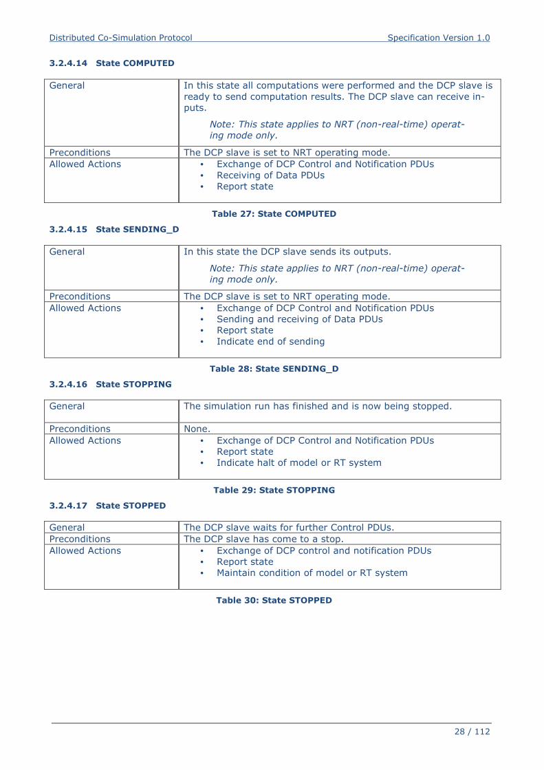
3.2.4.14 State COMPUTED
General
In this state all computations were performed and the DCP slave is
ready to send computation results. The DCP slave can receive in-
puts.
Note: This state applies to NRT (non-real-time) operat-
ing mode only.
Preconditions The DCP slave is set to NRT operating mode.
Allowed Actions
• Exchange of DCP Control and Notification PDUs
• Receiving of Data PDUs
• Report state
Table 27: State COMPUTED
3.2.4.15 State SENDING_D
General
In this state the DCP slave sends its outputs.
Note: This state applies to NRT (non-real-time) operat-
ing mode only.
Preconditions The DCP slave is set to NRT operating mode.
Allowed Actions
• Exchange of DCP Control and Notification PDUs
• Sending and receiving of Data PDUs
• Report state
• Indicate end of sending
Table 28: State SENDING_D
3.2.4.16 State STOPPING
General
The simulation run has finished and is now being stopped.
Preconditions None.
Allowed Actions
• Exchange of DCP Control and Notification PDUs
• Report state
• Indicate halt of model or RT system
Table 29: State STOPPING
3.2.4.17 State STOPPED
General The DCP slave waits for further Control PDUs.
Preconditions The DCP slave has come to a stop.
Allowed Actions
• Exchange of DCP control and notification PDUs
• Report state
• Maintain condition of model or RT system
Table 30: State STOPPED
Distributed Co-Simulation Protocol Specification Version 1.0
29 / 112
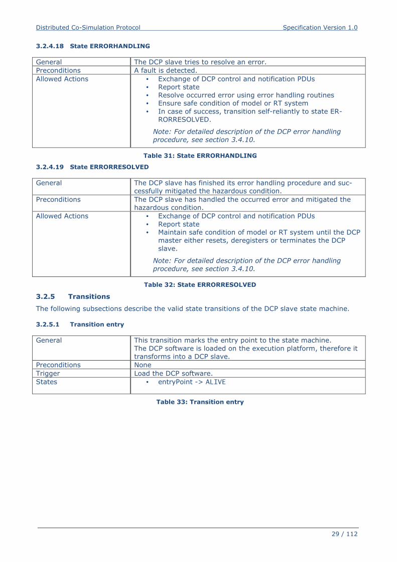
3.2.4.18 State ERRORHANDLING
General The DCP slave tries to resolve an error.
Preconditions A fault is detected.
Allowed Actions
• Exchange of DCP control and notification PDUs
• Report state
• Resolve occurred error using error handling routines
• Ensure safe condition of model or RT system
• In case of success, transition self-reliantly to state ER-
RORRESOLVED.
Note: For detailed description of the DCP error handling
procedure, see section 3.4.10.
Table 31: State ERRORHANDLING
3.2.4.19 State ERRORRESOLVED
General
The DCP slave has finished its error handling procedure and suc-
cessfully mitigated the hazardous condition.
Preconditions
The DCP slave has handled the occurred error and mitigated the
hazardous condition.
Allowed Actions
• Exchange of DCP control and notification PDUs
• Report state
• Maintain safe condition of model or RT system until the DCP
master either resets, deregisters or terminates the DCP
slave.
Note: For detailed description of the DCP error handling
procedure, see section 3.4.10.
Table 32: State ERRORRESOLVED
3.2.5 Transitions
The following subsections describe the valid state transitions of the DCP slave state machine.
3.2.5.1 Transition entry
General This transition marks the entry point to the state machine.
The DCP software is loaded on the execution platform, therefore it
transforms into a DCP slave.
Preconditions None
Trigger Load the DCP software.
States • entryPoint -> ALIVE
Table 33: Transition entry
Distributed Co-Simulation Protocol Specification Version 1.0
30 / 112
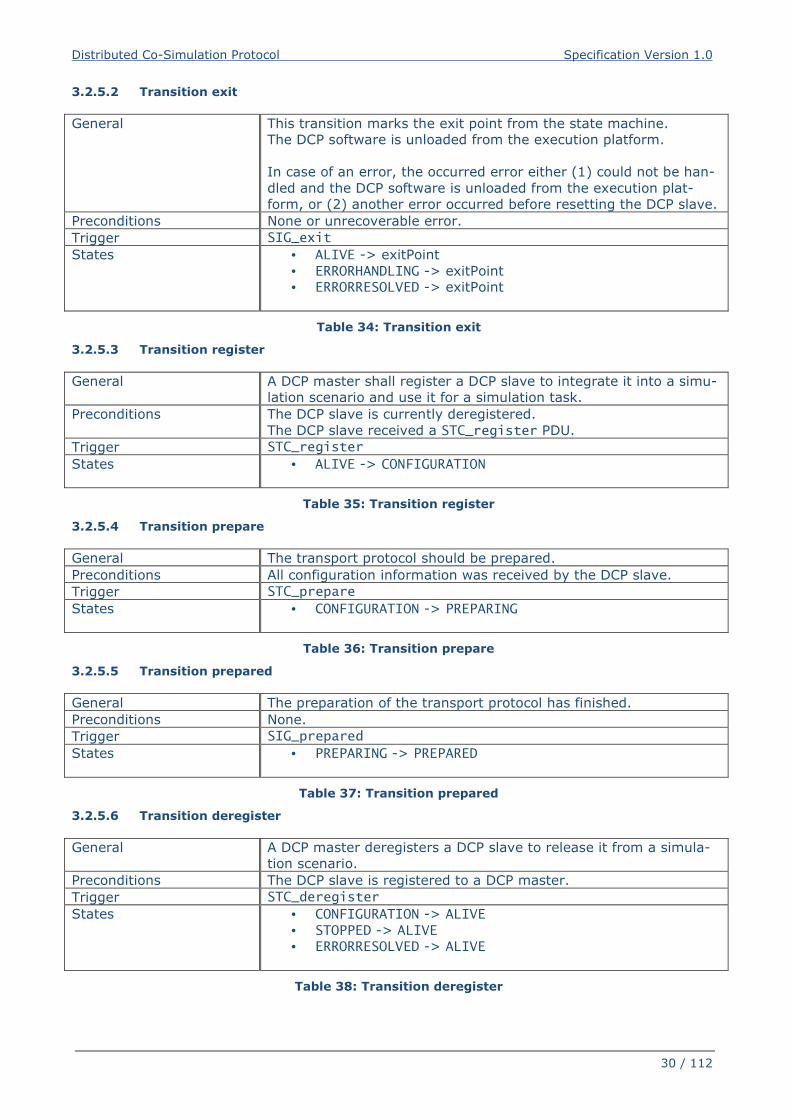
3.2.5.2 Transition exit
General This transition marks the exit point from the state machine.
The DCP software is unloaded from the execution platform.
In case of an error, the occurred error either (1) could not be han-
dled and the DCP software is unloaded from the execution plat-
form, or (2) another error occurred before resetting the DCP slave.
Preconditions None or unrecoverable error.
Trigger SIG_exit
States • ALIVE -> exitPoint
• ERRORHANDLING -> exitPoint
• ERRORRESOLVED -> exitPoint
Table 34: Transition exit
3.2.5.3 Transition register
General A DCP master shall register a DCP slave to integrate it into a simu-
lation scenario and use it for a simulation task.
Preconditions The DCP slave is currently deregistered.
The DCP slave received a STC_register PDU.
Trigger STC_register
States • ALIVE -> CONFIGURATION
Table 35: Transition register
3.2.5.4 Transition prepare
General The transport protocol should be prepared.
Preconditions All configuration information was received by the DCP slave.
Trigger STC_prepare
States • CONFIGURATION -> PREPARING
Table 36: Transition prepare
3.2.5.5 Transition prepared
General The preparation of the transport protocol has finished.
Preconditions None.
Trigger SIG_prepared
States • PREPARING -> PREPARED
Table 37: Transition prepared
3.2.5.6 Transition deregister
General A DCP master deregisters a DCP slave to release it from a simula-
tion scenario.
Preconditions The DCP slave is registered to a DCP master.
Trigger STC_deregister
States • CONFIGURATION -> ALIVE
• STOPPED -> ALIVE
• ERRORRESOLVED -> ALIVE
Table 38: Transition deregister
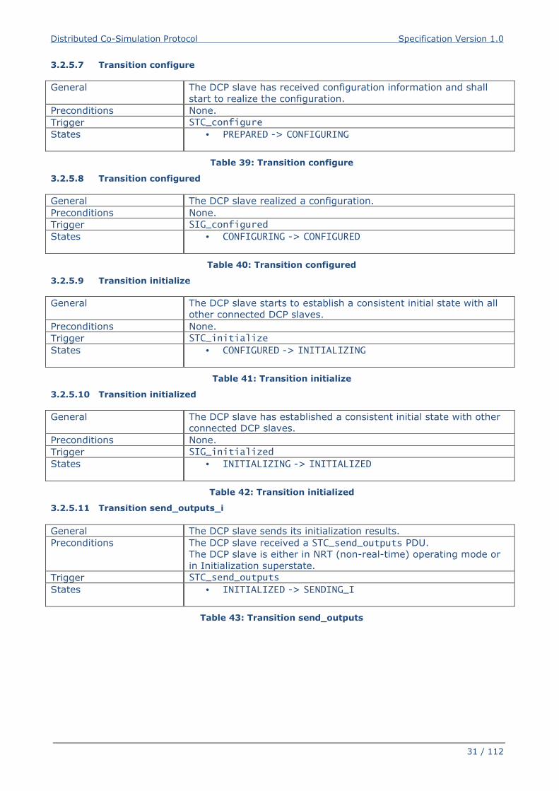
Distributed Co-Simulation Protocol Specification Version 1.0
31 / 112
3.2.5.7 Transition configure
General The DCP slave has received configuration information and shall
start to realize the configuration.
Preconditions None.
Trigger STC_configure
States • PREPARED -> CONFIGURING
Table 39: Transition configure
3.2.5.8 Transition configured
General The DCP slave realized a configuration.
Preconditions None.
Trigger SIG_configured
States • CONFIGURING -> CONFIGURED
Table 40: Transition configured
3.2.5.9 Transition initialize
General The DCP slave starts to establish a consistent initial state with all
other connected DCP slaves.
Preconditions None.
Trigger STC_initialize
States • CONFIGURED -> INITIALIZING
Table 41: Transition initialize
3.2.5.10 Transition initialized
General The DCP slave has established a consistent initial state with other
connected DCP slaves.
Preconditions None.
Trigger SIG_initialized
States • INITIALIZING -> INITIALIZED
Table 42: Transition initialized
3.2.5.11 Transition send_outputs_i
General The DCP slave sends its initialization results.
Preconditions The DCP slave received a STC_send_outputs PDU.
The DCP slave is either in NRT (non-real-time) operating mode or
in Initialization superstate.
Trigger STC_send_outputs
States • INITIALIZED -> SENDING_I
Table 43: Transition send_outputs
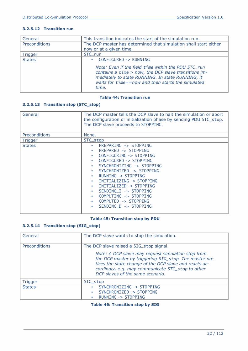
Distributed Co-Simulation Protocol Specification Version 1.0
32 / 112
3.2.5.12 Transition run
General This transition indicates the start of the simulation run.
Preconditions The DCP master has determined that simulation shall start either
now or at a given time.
Trigger STC_run
States • CONFIGURED -> RUNNING
Note: Even if the field time within the PDU STC_run
contains a time > now, the DCP slave transitions im-
mediately to state RUNNING. In state RUNNING, it
waits for time==now and then starts the simulated
time.
Table 44: Transition run
3.2.5.13 Transition stop (STC_stop)
General The DCP master tells the DCP slave to halt the simulation or abort
the configuration or initialization phase by sending PDU STC_stop.
The DCP slave proceeds to STOPPING.
Preconditions None.
Trigger STC_stop
States • PREPARING -> STOPPING • PREPARED -> STOPPING • CONFIGURING -> STOPPING
• CONFIGURED -> STOPPING
• SYNCHRONIZING -> STOPPING • SYNCHRONIZED -> STOPPING • RUNNING -> STOPPING
• INITIALIZING -> STOPPING
• INITIALIZED -> STOPPING
• SENDING_I -> STOPPING
• COMPUTING -> STOPPING
• COMPUTED -> STOPPING
• SENDING_D -> STOPPING
Table 45: Transition stop by PDU
3.2.5.14 Transition stop (SIG_stop)
General The DCP slave wants to stop the simulation.
Preconditions The DCP slave raised a SIG_stop signal.
Note: A DCP slave may request simulation stop from
the DCP master by triggering SIG_stop. The master no-
tices the state change of the DCP slave and reacts ac-
cordingly, e.g. may communicate STC_stop to other
DCP slaves of the same scenario.
Trigger SIG_stop
States • SYNCHRONIZING -> STOPPING
• SYNCHRONIZED -> STOPPING
• RUNNING -> STOPPING
Table 46: Transition stop by SIG
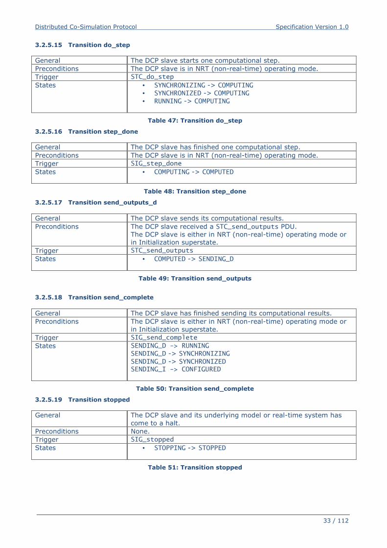
Distributed Co-Simulation Protocol Specification Version 1.0
33 / 112
3.2.5.15 Transition do_step
General The DCP slave starts one computational step.
Preconditions The DCP slave is in NRT (non-real-time) operating mode.
Trigger STC_do_step
States • SYNCHRONIZING -> COMPUTING
• SYNCHRONIZED -> COMPUTING
• RUNNING -> COMPUTING
Table 47: Transition do_step
3.2.5.16 Transition step_done
General The DCP slave has finished one computational step.
Preconditions The DCP slave is in NRT (non-real-time) operating mode.
Trigger SIG_step_done
States • COMPUTING -> COMPUTED
Table 48: Transition step_done
3.2.5.17 Transition send_outputs_d
General The DCP slave sends its computational results.
Preconditions The DCP slave received a STC_send_outputs PDU.
The DCP slave is either in NRT (non-real-time) operating mode or
in Initialization superstate.
Trigger STC_send_outputs
States • COMPUTED -> SENDING_D
Table 49: Transition send_outputs
3.2.5.18 Transition send_complete
General The DCP slave has finished sending its computational results.
Preconditions The DCP slave is either in NRT (non-real-time) operating mode or
in Initialization superstate.
Trigger SIG_send_complete
States SENDING_D -> RUNNING
SENDING_D -> SYNCHRONIZING
SENDING_D -> SYNCHRONIZED SENDING_I -> CONFIGURED
Table 50: Transition send_complete
3.2.5.19 Transition stopped
General The DCP slave and its underlying model or real-time system has
come to a halt.
Preconditions None.
Trigger SIG_stopped
States • STOPPING -> STOPPED
Table 51: Transition stopped
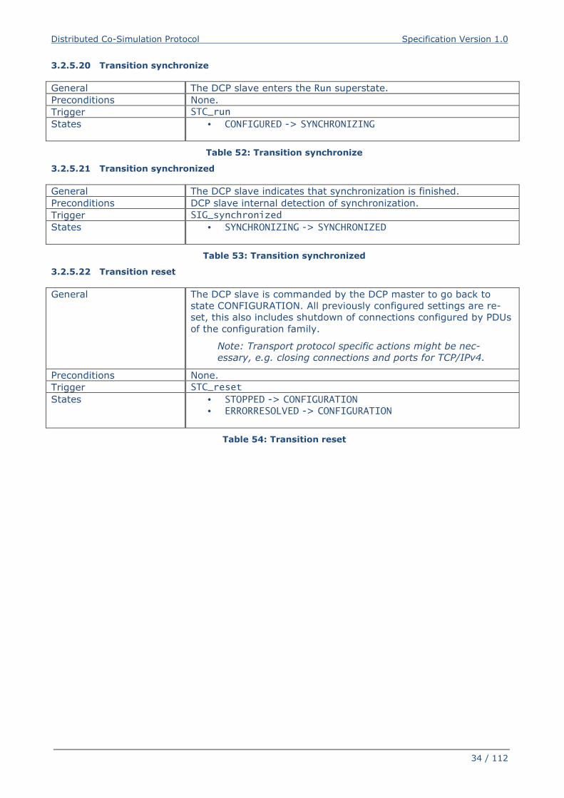
Distributed Co-Simulation Protocol Specification Version 1.0
34 / 112
3.2.5.20 Transition synchronize
General The DCP slave enters the Run superstate.
Preconditions None.
Trigger STC_run
States • CONFIGURED -> SYNCHRONIZING
Table 52: Transition synchronize
3.2.5.21 Transition synchronized
General The DCP slave indicates that synchronization is finished.
Preconditions DCP slave internal detection of synchronization.
Trigger SIG_synchronized
States • SYNCHRONIZING -> SYNCHRONIZED
Table 53: Transition synchronized
3.2.5.22 Transition reset
General The DCP slave is commanded by the DCP master to go back to
state CONFIGURATION. All previously configured settings are re-
set, this also includes shutdown of connections configured by PDUs
of the configuration family.
Note: Transport protocol specific actions might be nec-
essary, e.g. closing connections and ports for TCP/IPv4.
Preconditions None.
Trigger STC_reset
States • STOPPED -> CONFIGURATION
• ERRORRESOLVED -> CONFIGURATION
Table 54: Transition reset
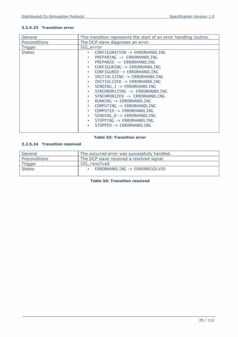
Distributed Co-Simulation Protocol Specification Version 1.0
35 / 112
3.2.5.23 Transition error
General This transition represents the start of an error handling routine.
Preconditions The DCP slave diagnoses an error.
Trigger SIG_error
States • CONFIGURATION -> ERRORHANDLING
• PREPARING -> ERRORHANDLING • PREPARED -> ERRORHANDLING • CONFIGURING -> ERRORHANDLING
• CONFIGURED -> ERRORHANDLING
• INITIALIZING -> ERRORHANDLING
• INITIALIZED -> ERRORHANDLING
• SENDING_I -> ERRORHANDLING
• SYNCHRONIZING -> ERRORHANDLING • SYNCHRONIZED -> ERRORHANDLING
• RUNNING -> ERRORHANDLING
• COMPUTING -> ERRORHANDLING
• COMPUTED -> ERRORHANDLING
• SENDING_D -> ERRORHANDLING
• STOPPING -> ERRORHANDLING
• STOPPED -> ERRORHANDLING
Table 55: Transition error
3.2.5.24 Transition resolved
General The occurred error was successfully handled.
Preconditions The DCP slave received a resolved signal.
Trigger SIG_resolved
States • ERRORHANDLING -> ERRORRESOLVED
Table 56: Transition resolved
Distributed Co-Simulation Protocol Specification Version 1.0
36 / 112
3.3 PDU Definitions
3.3.1 General
Protocol Data Units (PDUs) are transmitted via abstract channels. In practice, a communication
medium must be used. DCP PDUs are categorized in families. Configuration request (CFG), state
change request (STC), and information request (INF) PDUs belong to the family of Request
PDUs. Together with the family of response (RSP) PDUs they make up the family of Control
PDUs. The families of Notification PDUs (NTF) and Data PDUs (DAT) complete the range of avail-
able PDU families.
Control PDUs are exchanged between DCP master and DCP slaves. PDUs of the families CFG,
STC and INF are only sent from the DCP master to its DCP slaves and are acknowledged by the
DCP slaves via RSP PDUs. Data PDUs are not acknowledged.
If the DCP master sets up a scenario where the master relays Data between DCP slaves, then
also a DCP master may send and receive Data PDUs.
Note: Data PDUs are not acknowledged. To ensure that corruption, loss, reordering,
etc. of Data PDUs is avoided, a reliable communication medium must be used. See
also section 10-F.
3.3.2 Structuring
All PDUs are structured using fields. A field is defined by its name, a DCP compliant data type,
and the position of the field within the PDU, given in bytes. Table 57 provides an overview of all
specified PDU fields and their corresponding data types. Concrete PDUs are distinguished by their
type (field: type_id). For all PDUs, the type_id is available at the beginning at position zero with
a length of 1 byte. A specific PDU does not contain all remaining fields, but only those required
for the specific use, as can be seen in Table 62. The upcoming subsections give detailed infor-
mation about each PDU.
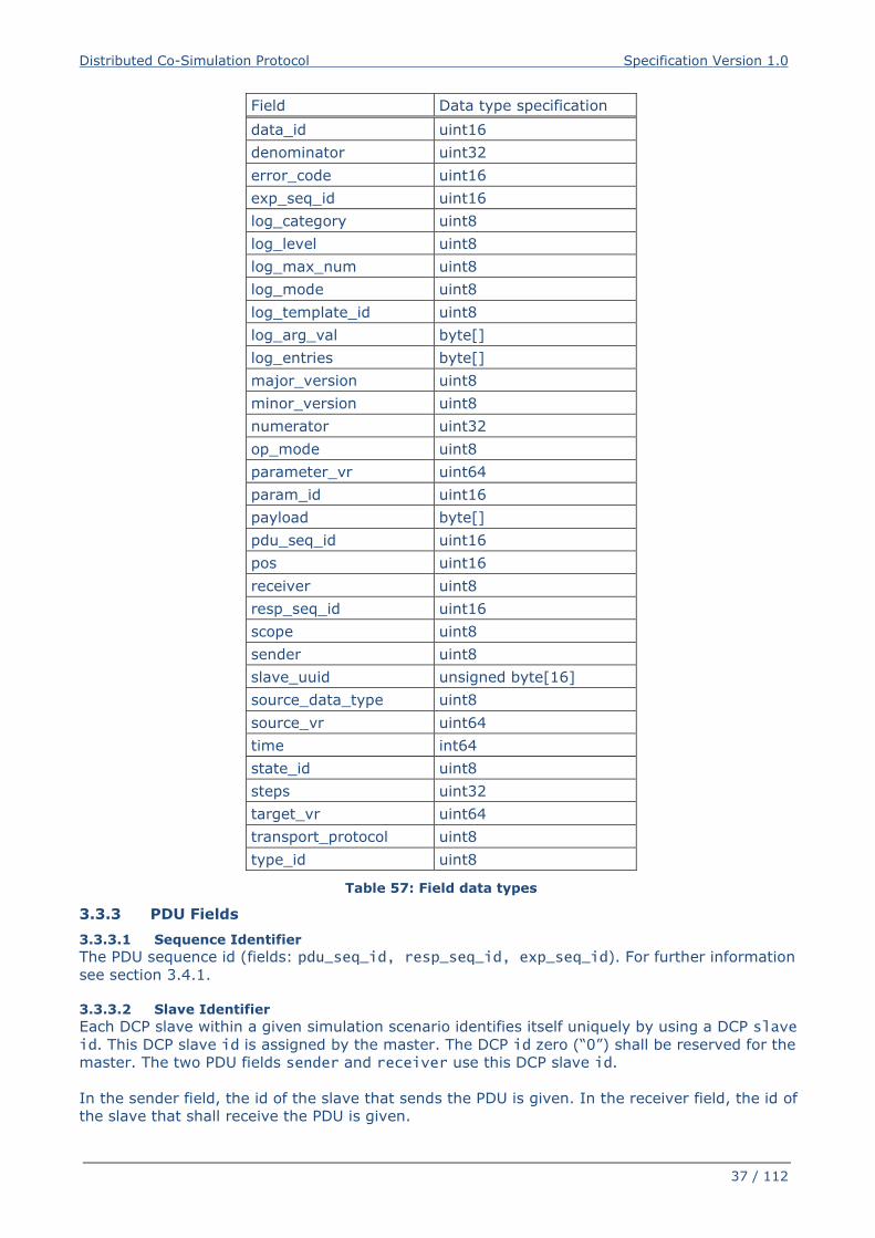
Distributed Co-Simulation Protocol Specification Version 1.0
37 / 112
Field Data type specification
data_id uint16
denominator uint32
error_code uint16
exp_seq_id uint16
log_category uint8
log_level uint8
log_max_num uint8
log_mode uint8
log_template_id uint8
log_arg_val byte[]
log_entries byte[]
major_version uint8
minor_version uint8
numerator uint32
op_mode uint8
parameter_vr uint64
param_id uint16
payload byte[]
pdu_seq_id uint16
pos uint16
receiver uint8
resp_seq_id uint16
scope uint8
sender uint8
slave_uuid unsigned byte[16]
source_data_type uint8
source_vr uint64
time int64
state_id uint8
steps uint32
target_vr uint64
transport_protocol uint8
type_id uint8
Table 57: Field data types
3.3.3 PDU Fields
3.3.3.1 Sequence Identifier
The PDU sequence id (fields: pdu_seq_id, resp_seq_id, exp_seq_id). For further information
see section 3.4.1.
3.3.3.2 Slave Identifier
Each DCP slave within a given simulation scenario identifies itself uniquely by using a DCP slave id. This DCP slave id is assigned by the master. The DCP id zero (“0”) shall be reserved for the
master. The two PDU fields sender and receiver use this DCP slave id.
In the sender field, the id of the slave that sends the PDU is given. In the receiver field, the id of
the slave that shall receive the PDU is given.
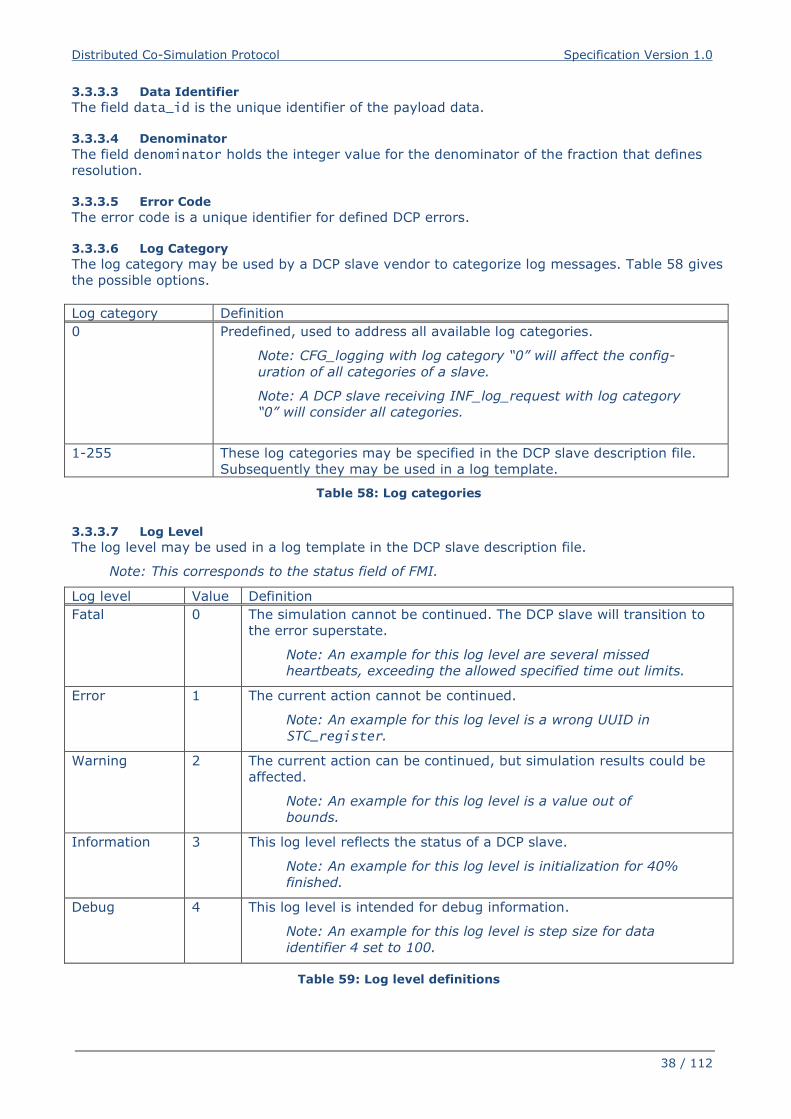
Distributed Co-Simulation Protocol Specification Version 1.0
38 / 112
3.3.3.3 Data Identifier
The field data_id is the unique identifier of the payload data.
3.3.3.4 Denominator
The field denominator holds the integer value for the denominator of the fraction that defines
resolution.
3.3.3.5 Error Code
The error code is a unique identifier for defined DCP errors.
3.3.3.6 Log Category
The log category may be used by a DCP slave vendor to categorize log messages. Table 58 gives
the possible options.
Log category Definition
0 Predefined, used to address all available log categories.
Note: CFG_logging with log category “0” will affect the config-
uration of all categories of a slave.
Note: A DCP slave receiving INF_log_request with log category
“0” will consider all categories.
1-255 These log categories may be specified in the DCP slave description file.
Subsequently they may be used in a log template.
Table 58: Log categories
3.3.3.7 Log Level
The log level may be used in a log template in the DCP slave description file.
Note: This corresponds to the status field of FMI.
Log level Value Definition
Fatal 0 The simulation cannot be continued. The DCP slave will transition to
the error superstate.
Note: An example for this log level are several missed
heartbeats, exceeding the allowed specified time out limits.
Error 1 The current action cannot be continued.
Note: An example for this log level is a wrong UUID in
STC_register.
Warning 2 The current action can be continued, but simulation results could be
affected.
Note: An example for this log level is a value out of
bounds.
Information 3 This log level reflects the status of a DCP slave.
Note: An example for this log level is initialization for 40%
finished.
Debug 4 This log level is intended for debug information.
Note: An example for this log level is step size for data
identifier 4 set to 100.
Table 59: Log level definitions
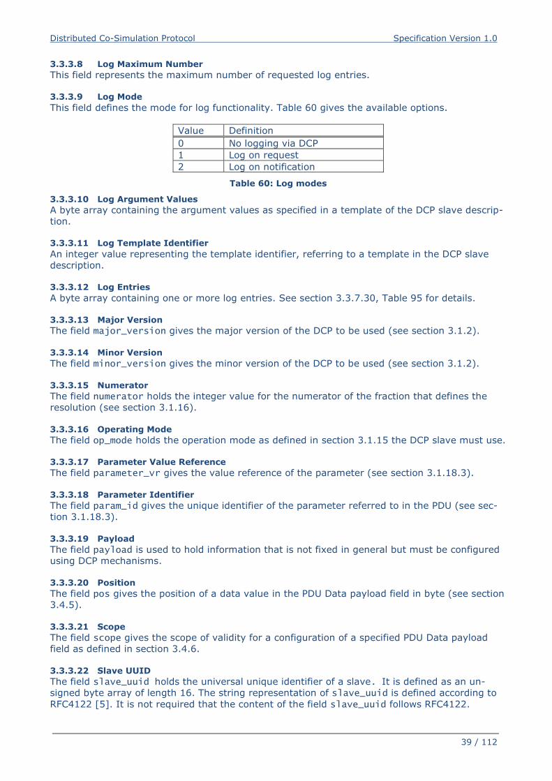
Distributed Co-Simulation Protocol Specification Version 1.0
39 / 112
3.3.3.8 Log Maximum Number
This field represents the maximum number of requested log entries.
3.3.3.9 Log Mode
This field defines the mode for log functionality. Table 60 gives the available options.
Value Definition
0 No logging via DCP
1 Log on request
2 Log on notification
Table 60: Log modes
3.3.3.10 Log Argument Values
A byte array containing the argument values as specified in a template of the DCP slave descrip-
tion.
3.3.3.11 Log Template Identifier
An integer value representing the template identifier, referring to a template in the DCP slave
description.
3.3.3.12 Log Entries
A byte array containing one or more log entries. See section 3.3.7.30, Table 95 for details.
3.3.3.13 Major Version
The field major_version gives the major version of the DCP to be used (see section 3.1.2).
3.3.3.14 Minor Version
The field minor_version gives the minor version of the DCP to be used (see section 3.1.2). 3.3.3.15 Numerator
The field numerator holds the integer value for the numerator of the fraction that defines the
resolution (see section 3.1.16).
3.3.3.16 Operating Mode
The field op_mode holds the operation mode as defined in section 3.1.15 the DCP slave must use.
3.3.3.17 Parameter Value Reference
The field parameter_vr gives the value reference of the parameter (see section 3.1.18.3).
3.3.3.18 Parameter Identifier
The field param_id gives the unique identifier of the parameter referred to in the PDU (see sec-
tion 3.1.18.3).
3.3.3.19 Payload
The field payload is used to hold information that is not fixed in general but must be configured
using DCP mechanisms.
3.3.3.20 Position
The field pos gives the position of a data value in the PDU Data payload field in byte (see section
3.4.5).
3.3.3.21 Scope
The field scope gives the scope of validity for a configuration of a specified PDU Data payload
field as defined in section 3.4.6.
3.3.3.22 Slave UUID
The field slave_uuid holds the universal unique identifier of a slave. It is defined as an un-
signed byte array of length 16. The string representation of slave_uuid is defined according to
RFC4122 [5]. It is not required that the content of the field slave_uuid follows RFC4122.
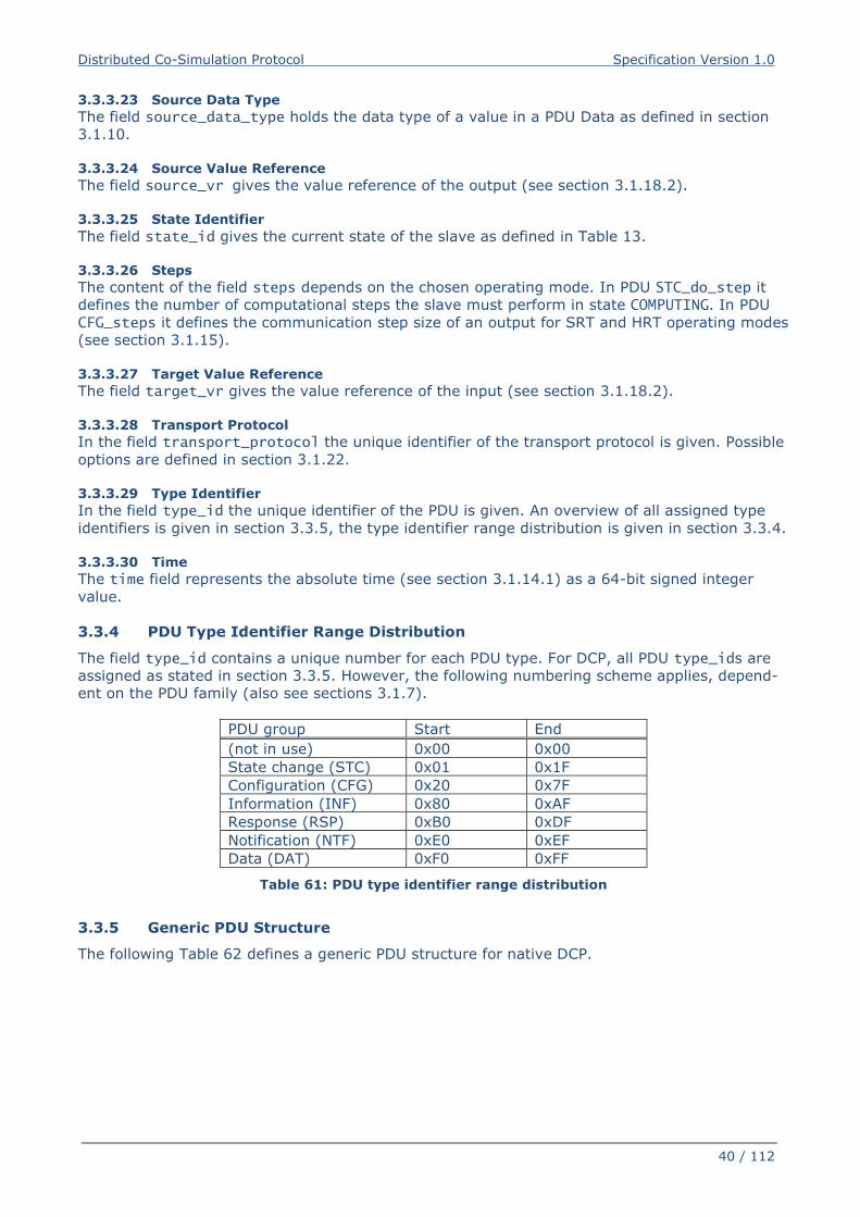
Distributed Co-Simulation Protocol Specification Version 1.0
40 / 112
3.3.3.23 Source Data Type
The field source_data_type holds the data type of a value in a PDU Data as defined in section
3.1.10.
3.3.3.24 Source Value Reference
The field source_vr gives the value reference of the output (see section 3.1.18.2).
3.3.3.25 State Identifier
The field state_id gives the current state of the slave as defined in Table 13.
3.3.3.26 Steps
The content of the field steps depends on the chosen operating mode. In PDU STC_do_step it
defines the number of computational steps the slave must perform in state COMPUTING. In PDU
CFG_steps it defines the communication step size of an output for SRT and HRT operating modes
(see section 3.1.15).
3.3.3.27 Target Value Reference
The field target_vr gives the value reference of the input (see section 3.1.18.2).
3.3.3.28 Transport Protocol
In the field transport_protocol the unique identifier of the transport protocol is given. Possible
options are defined in section 3.1.22.
3.3.3.29 Type Identifier
In the field type_id the unique identifier of the PDU is given. An overview of all assigned type
identifiers is given in section 3.3.5, the type identifier range distribution is given in section 3.3.4.
3.3.3.30 Time
The time field represents the absolute time (see section 3.1.14.1) as a 64-bit signed integer
value.
3.3.4 PDU Type Identifier Range Distribution
The field type_id contains a unique number for each PDU type. For DCP, all PDU type_ids are
assigned as stated in section 3.3.5. However, the following numbering scheme applies, depend-
ent on the PDU family (also see sections 3.1.7).
PDU group Start End
(not in use) 0x00 0x00
State change (STC) 0x01 0x1F
Configuration (CFG) 0x20 0x7F
Information (INF) 0x80 0xAF
Response (RSP) 0xB0 0xDF
Notification (NTF) 0xE0 0xEF
Data (DAT) 0xF0 0xFF
Table 61: PDU type identifier range distribution
3.3.5 Generic PDU Structure
The following Table 62 defines a generic PDU structure for native DCP.
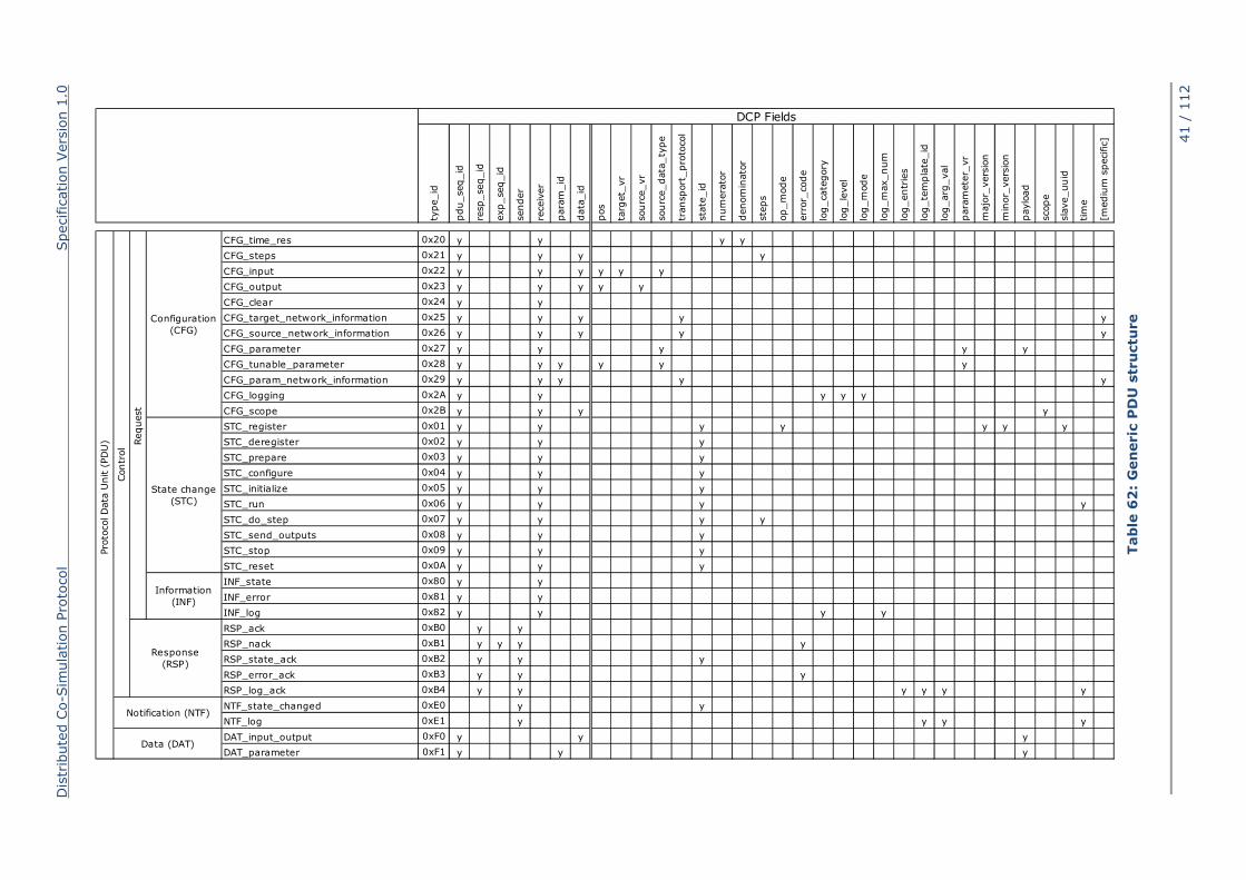
Dis
trib
ute
d C
o-S
imula
tion P
roto
col
Specific
ation V
ers
ion 1
.0
41 /
112
Tab
le 6
2:
Gen
eric
PD
U s
tru
ctu
re
type_id
pdu_seq_id
resp_seq_id
exp_seq_id
sender
receiv
er
para
m_id
data
_id
pos
targ
et_
vr
sourc
e_vr
sourc
e_data
_ty
pe
transport
_pro
tocol
sta
te_id
num
era
tor
denom
inato
r
ste
ps
op_m
ode
err
or_
code
log_cate
gory
log_le
vel
log_m
ode
log_m
ax_num
log_entr
ies
log_te
mpla
te_id
log_arg
_val
para
mete
r_vr
majo
r_vers
ion
min
or_
vers
ion
paylo
ad
scope
sla
ve_uuid
tim
e
[mediu
m s
pecific
]
CFG_time_res 0x20 y y y y
CFG_steps 0x21 y y y y
CFG_input 0x22 y y y y y y
CFG_output 0x23 y y y y y
CFG_clear 0x24 y y
CFG_target_network_information 0x25 y y y y y
CFG_source_network_information 0x26 y y y y y
CFG_parameter 0x27 y y y y y
CFG_tunable_parameter 0x28 y y y y y y
CFG_param_network_information 0x29 y y y y y
CFG_logging 0x2A y y y y y
CFG_scope 0x2B y y y y
STC_register 0x01 y y y y y y y
STC_deregister 0x02 y y y
STC_prepare 0x03 y y y
STC_configure 0x04 y y y
STC_initialize 0x05 y y y
STC_run 0x06 y y y y
STC_do_step 0x07 y y y y
STC_send_outputs 0x08 y y y
STC_stop 0x09 y y y
STC_reset 0x0A y y y
INF_state 0x80 y y
INF_error 0x81 y y
INF_log 0x82 y y y y
RSP_ack 0xB0 y y
RSP_nack 0xB1 y y y y
RSP_state_ack 0xB2 y y y
RSP_error_ack 0xB3 y y y
RSP_log_ack 0xB4 y y y y y y
NTF_state_changed 0xE0 y y
NTF_log 0xE1 y y y y
DAT_input_output 0xF0 y y y
DAT_parameter 0xF1 y y y
DCP Fields
Data (DAT)
Pro
tocol D
ata
Unit (
PD
U)
State change
(STC)
Notification (NTF)
Response
(RSP)
Contr
ol
Information
(INF)
Request
Configuration
(CFG)
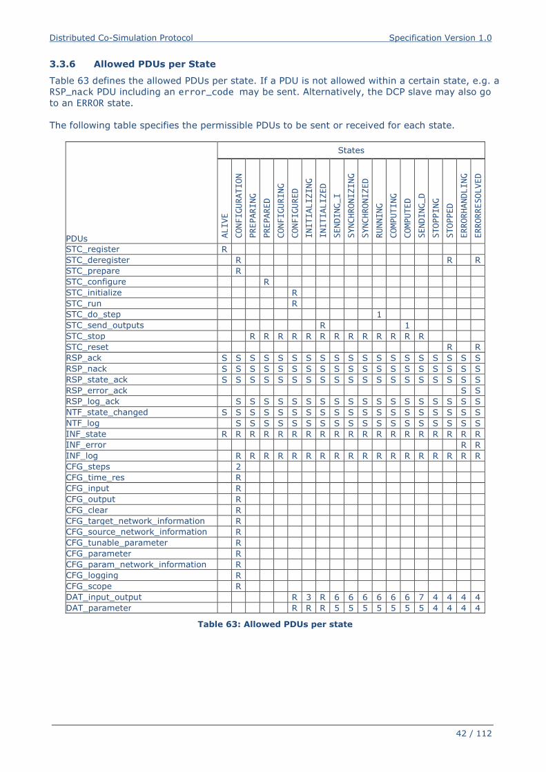
Distributed Co-Simulation Protocol Specification Version 1.0
42 / 112
3.3.6 Allowed PDUs per State
Table 63 defines the allowed PDUs per state. If a PDU is not allowed within a certain state, e.g. a
RSP_nack PDU including an error_code may be sent. Alternatively, the DCP slave may also go
to an ERROR state.
The following table specifies the permissible PDUs to be sent or received for each state.
PDUs
States
ALIVE
CONFIGURATION
PREPARING
PREPARED
CONFIGURING
CONFIGURED
INITIALIZING
INITIALIZED
SENDING_I
SYNCHRONIZING
SYNCHRONIZED
RUNNING
COMPUTING
COMPUTED
SENDING_D
STOPPING
STOPPED
ERRORHANDLING
ERRORRESOLVED
STC_register R
STC_deregister R R R
STC_prepare R
STC_configure R
STC_initialize R
STC_run R
STC_do_step 1
STC_send_outputs R 1
STC_stop R R R R R R R R R R R R R
STC_reset R R
RSP_ack S S S S S S S S S S S S S S S S S S S
RSP_nack S S S S S S S S S S S S S S S S S S S
RSP_state_ack S S S S S S S S S S S S S S S S S S S
RSP_error_ack S S
RSP_log_ack S S S S S S S S S S S S S S S S S S
NTF_state_changed S S S S S S S S S S S S S S S S S S S
NTF_log S S S S S S S S S S S S S S S S S S
INF_state R R R R R R R R R R R R R R R R R R R
INF_error R R
INF_log R R R R R R R R R R R R R R R R R R
CFG_steps 2
CFG_time_res R
CFG_input R
CFG_output R
CFG_clear R
CFG_target_network_information R
CFG_source_network_information R
CFG_tunable_parameter R
CFG_parameter R
CFG_param_network_information R
CFG_logging R
CFG_scope R
DAT_input_output R 3 R 6 6 6 6 6 6 7 4 4 4 4
DAT_parameter R R R 5 5 5 5 5 5 5 4 4 4 4
Table 63: Allowed PDUs per state
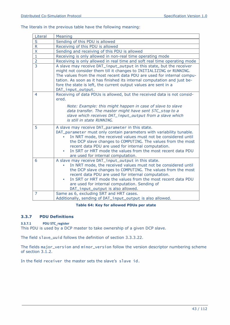
Distributed Co-Simulation Protocol Specification Version 1.0
43 / 112
The literals in the previous table have the following meaning:
Literal Meaning
S Sending of this PDU is allowed
R Receiving of this PDU is allowed
X Sending and receiving of this PDU is allowed
1 Receiving is only allowed in non-real time operating mode
2 Receiving is only allowed in real time and soft real time operating mode
3 A slave may receive DAT_input_output in this state, but the receiver
might not consider them till it changes to INITIALIZING or RUNNING.
The values from the most recent data PDU are used for internal compu-
tation. As soon as it has finished its internal computation and just be-
fore the state is left, the current output values are sent in a
DAT_input_output.
4 Receiving of data PDUs is allowed, but the received data is not consid-
ered.
Note: Example: this might happen in case of slave to slave
data transfer. The master might have sent STC_stop to a
slave which receives DAT_input_output from a slave which
is still in state RUNNING.
5 A slave may receive DAT_parameter in this state.
DAT_parameter must only contain parameters with variability tunable.
• In NRT mode, the received values must not be considered until
the DCP slave changes to COMPUTING. The values from the most
recent data PDU are used for internal computation.
• In SRT or HRT mode the values from the most recent data PDU
are used for internal computation.
6 A slave may receive DAT_input_output in this state.
• In NRT mode, the received values must not be considered until
the DCP slave changes to COMPUTING. The values from the most
recent data PDU are used for internal computation.
• In SRT or HRT mode the values from the most recent data PDU
are used for internal computation. Sending of
DAT_input_output is also allowed.
7 Same as 6, excluding SRT and HRT cases.
Additionally, sending of DAT_input_output is also allowed.
Table 64: Key for allowed PDUs per state
3.3.7 PDU Definitions
3.3.7.1 PDU STC_register
This PDU is used by a DCP master to take ownership of a given DCP slave.
The field slave_uuid follows the definition of section 3.3.3.22.
The fields major_version and minor_version follow the version descriptor numbering scheme
of section 3.1.2.
In the field receiver the master sets the slave’s slave id.
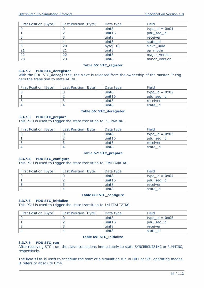
Distributed Co-Simulation Protocol Specification Version 1.0
44 / 112
First Position [Byte] Last Position [Byte] Data type Field
0 0 uint8 type_id = 0x01
1 2 unit16 pdu_seq_id
3 3 uint8 receiver
4 4 uint8 state_id
5 20 byte[16] slave_uuid
21 21 uint8 op_mode
22 22 uint8 major_version
23 23 uint8 minor_version
Table 65: STC_register
3.3.7.2 PDU STC_deregister
With the PDU STC_deregister, the slave is released from the ownership of the master. It trig-
gers the transition to state ALIVE.
First Position [Byte] Last Position [Byte] Data type Field
0 0 uint8 type_id = 0x02
1 2 unit16 pdu_seq_id
3 3 uint8 receiver
4 4 uint8 state_id
Table 66: STC_deregister
3.3.7.3 PDU STC_prepare
This PDU is used to trigger the state transition to PREPARING.
First Position [Byte] Last Position [Byte] Data type Field
0 0 uint8 type_id = 0x03
1 2 unit16 pdu_seq_id
3 3 uint8 receiver
4 4 uint8 state_id
Table 67: STC_prepare
3.3.7.4 PDU STC_configure
This PDU is used to trigger the state transition to CONFIGURING.
First Position [Byte] Last Position [Byte] Data type Field
0 0 uint8 type_id = 0x04
1 2 unit16 pdu_seq_id
3 3 uint8 receiver
4 4 uint8 state_id
Table 68: STC_configure
3.3.7.5 PDU STC_initialize
This PDU is used to trigger the state transition to INITIALIZING.
First Position [Byte] Last Position [Byte] Data type Field
0 0 uint8 type_id = 0x05
1 2 unit16 pdu_seq_id
3 3 uint8 receiver
4 4 uint8 state_id
Table 69: STC_initialize
3.3.7.6 PDU STC_run
After receiving STC_run, the slave transitions immediately to state SYNCHRONIZING or RUNNING,
respectively.
The field time is used to schedule the start of a simulation run in HRT or SRT operating modes.
It refers to absolute time.
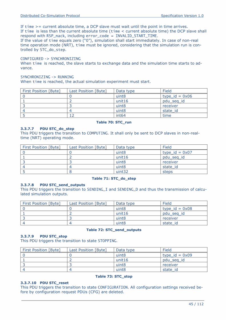
Distributed Co-Simulation Protocol Specification Version 1.0
45 / 112
If time >= current absolute time, a DCP slave must wait until the point in time arrives.
If time is less than the current absolute time (time < current absolute time) the DCP slave shall
respond with RSP_nack, including error_code = INVALID_START_TIME.
If the value of time equals zero (“0”), simulation shall start immediately. In case of non-real
time operation mode (NRT), time must be ignored, considering that the simulation run is con-
trolled by STC_do_step.
CONFIGURED -> SYNCHRONIZING
When time is reached, the slave starts to exchange data and the simulation time starts to ad-
vance.
SYNCHRONIZING -> RUNNING
When time is reached, the actual simulation experiment must start.
First Position [Byte] Last Position [Byte] Data type Field
0 0 uint8 type_id = 0x06
1 2 unit16 pdu_seq_id
3 3 uint8 receiver
4 4 uint8 state_id
5 12 int64 time
Table 70: STC_run
3.3.7.7 PDU STC_do_step
This PDU triggers the transition to COMPUTING. It shall only be sent to DCP slaves in non-real-
time (NRT) operating mode.
First Position [Byte] Last Position [Byte] Data type Field
0 0 uint8 type_id = 0x07
1 2 unit16 pdu_seq_id
3 3 uint8 receiver
4 4 uint8 state_id
5 8 uint32 steps
Table 71: STC_do_step
3.3.7.8 PDU STC_send_outputs
This PDU triggers the transition to SENDING_I and SENDING_D and thus the transmission of calcu-
lated simulation outputs.
First Position [Byte] Last Position [Byte] Data type Field
0 0 uint8 type_id = 0x08
1 2 unit16 pdu_seq_id
3 3 uint8 receiver
4 4 uint8 state_id
Table 72: STC_send_outputs
3.3.7.9 PDU STC_stop
This PDU triggers the transition to state STOPPING.
First Position [Byte] Last Position [Byte] Data type Field
0 0 uint8 type_id = 0x09
1 2 unit16 pdu_seq_id
3 3 uint8 receiver
4 4 uint8 state_id
Table 73: STC_stop
3.3.7.10 PDU STC_reset
This PDU triggers the transition to state CONFIGURATION. All configuration settings received be-
fore by configuration request PDUs (CFG) are deleted.
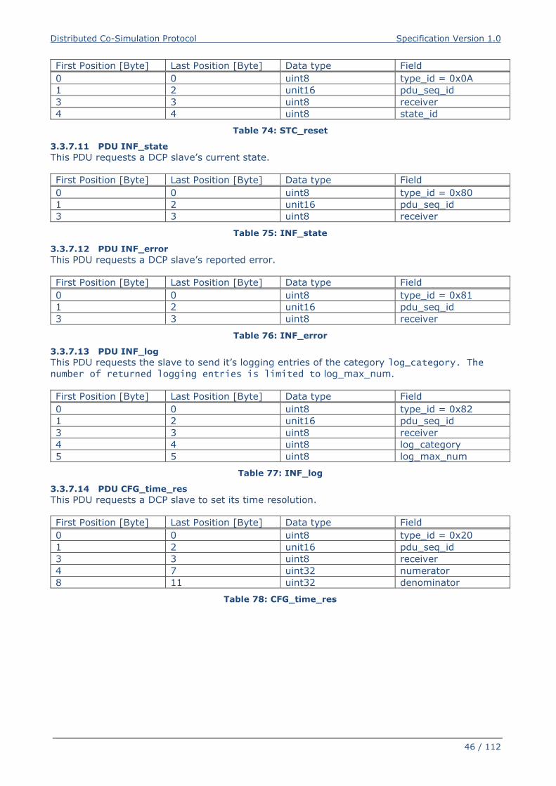
Distributed Co-Simulation Protocol Specification Version 1.0
46 / 112
First Position [Byte] Last Position [Byte] Data type Field
0 0 uint8 type_id = 0x0A
1 2 unit16 pdu_seq_id
3 3 uint8 receiver
4 4 uint8 state_id
Table 74: STC_reset
3.3.7.11 PDU INF_state
This PDU requests a DCP slave’s current state.
First Position [Byte] Last Position [Byte] Data type Field
0 0 uint8 type_id = 0x80
1 2 unit16 pdu_seq_id
3 3 uint8 receiver
Table 75: INF_state
3.3.7.12 PDU INF_error
This PDU requests a DCP slave’s reported error.
First Position [Byte] Last Position [Byte] Data type Field
0 0 uint8 type_id = 0x81
1 2 unit16 pdu_seq_id
3 3 uint8 receiver
Table 76: INF_error
3.3.7.13 PDU INF_log
This PDU requests the slave to send it’s logging entries of the category log_category. The number of returned logging entries is limited to log_max_num.
First Position [Byte] Last Position [Byte] Data type Field
0 0 uint8 type_id = 0x82
1 2 unit16 pdu_seq_id
3 3 uint8 receiver
4 4 uint8 log_category
5 5 uint8 log_max_num
Table 77: INF_log
3.3.7.14 PDU CFG_time_res
This PDU requests a DCP slave to set its time resolution.
First Position [Byte] Last Position [Byte] Data type Field
0 0 uint8 type_id = 0x20
1 2 unit16 pdu_seq_id
3 3 uint8 receiver
4 7 uint32 numerator
8 11 uint32 denominator
Table 78: CFG_time_res
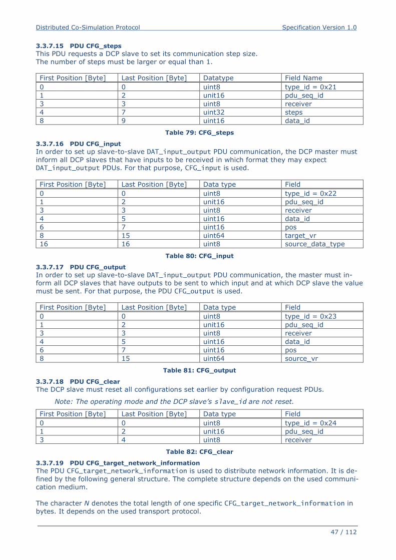
Distributed Co-Simulation Protocol Specification Version 1.0
47 / 112
3.3.7.15 PDU CFG_steps
This PDU requests a DCP slave to set its communication step size.
The number of steps must be larger or equal than 1.
First Position [Byte] Last Position [Byte] Datatype Field Name
0 0 uint8 type_id = 0x21
1 2 unit16 pdu_seq_id
3 3 uint8 receiver
4 7 uint32 steps
8 9 uint16 data_id
Table 79: CFG_steps
3.3.7.16 PDU CFG_input
In order to set up slave-to-slave DAT_input_output PDU communication, the DCP master must
inform all DCP slaves that have inputs to be received in which format they may expect
DAT_input_output PDUs. For that purpose, CFG_input is used.
First Position [Byte] Last Position [Byte] Data type Field
0 0 uint8 type_id = 0x22
1 2 unit16 pdu_seq_id
3 3 uint8 receiver
4 5 uint16 data_id
6 7 uint16 pos
8 15 uint64 target_vr
16 16 uint8 source_data_type
Table 80: CFG_input
3.3.7.17 PDU CFG_output
In order to set up slave-to-slave DAT_input_output PDU communication, the master must in-
form all DCP slaves that have outputs to be sent to which input and at which DCP slave the value
must be sent. For that purpose, the PDU CFG_output is used.
First Position [Byte] Last Position [Byte] Data type Field
0 0 uint8 type_id = 0x23
1 2 unit16 pdu_seq_id
3 3 uint8 receiver
4 5 uint16 data_id
6 7 uint16 pos
8 15 uint64 source_vr
Table 81: CFG_output
3.3.7.18 PDU CFG_clear
The DCP slave must reset all configurations set earlier by configuration request PDUs.
Note: The operating mode and the DCP slave’s slave_id are not reset.
First Position [Byte] Last Position [Byte] Data type Field
0 0 uint8 type_id = 0x24
1 2 unit16 pdu_seq_id
3 4 uint8 receiver
Table 82: CFG_clear
3.3.7.19 PDU CFG_target_network_information
The PDU CFG_target_network_information is used to distribute network information. It is de-
fined by the following general structure. The complete structure depends on the used communi-
cation medium.
The character N denotes the total length of one specific CFG_target_network_information in
bytes. It depends on the used transport protocol.
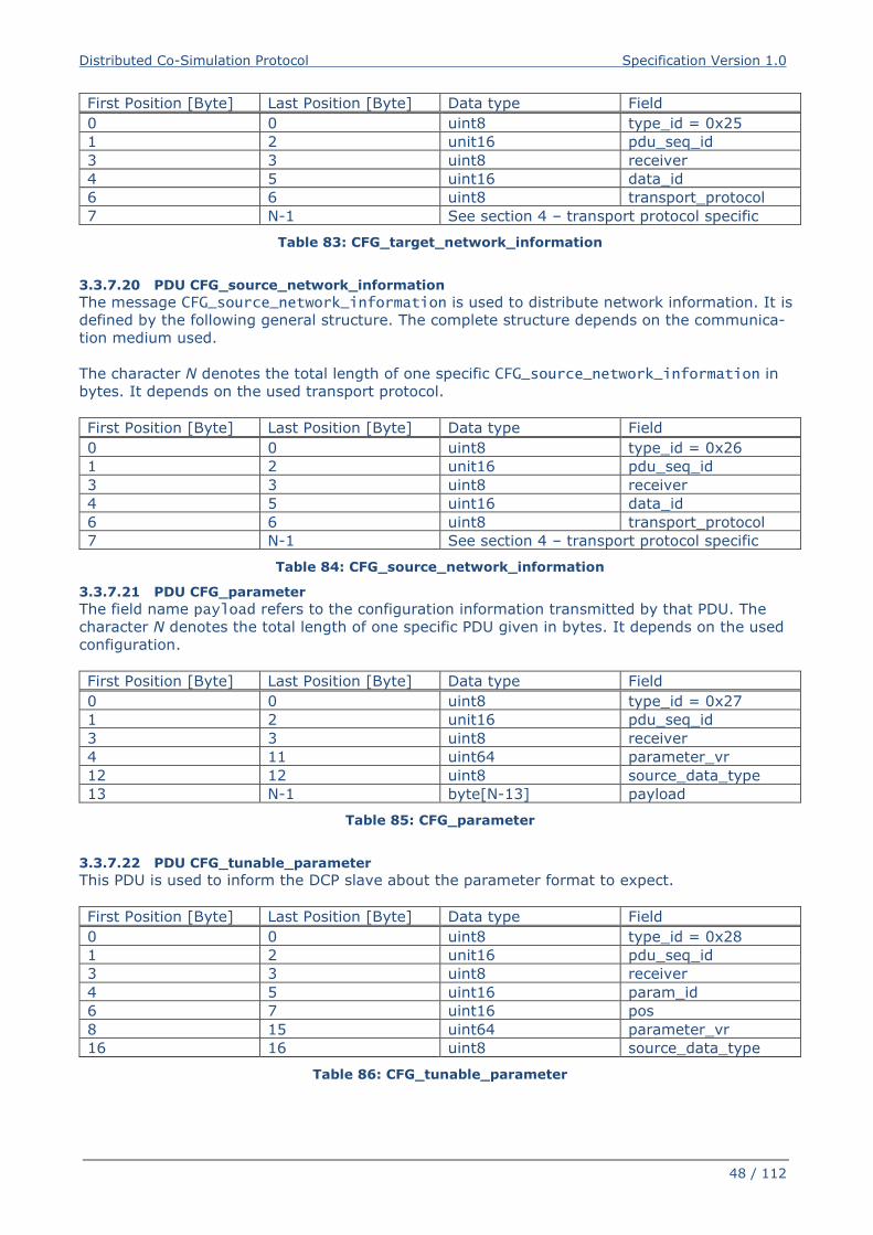
Distributed Co-Simulation Protocol Specification Version 1.0
48 / 112
First Position [Byte] Last Position [Byte] Data type Field
0 0 uint8 type_id = 0x25
1 2 unit16 pdu_seq_id
3 3 uint8 receiver
4 5 uint16 data_id
6 6 uint8 transport_protocol
7 N-1 See section 4 – transport protocol specific
Table 83: CFG_target_network_information
3.3.7.20 PDU CFG_source_network_information
The message CFG_source_network_information is used to distribute network information. It is
defined by the following general structure. The complete structure depends on the communica-
tion medium used.
The character N denotes the total length of one specific CFG_source_network_information in
bytes. It depends on the used transport protocol.
First Position [Byte] Last Position [Byte] Data type Field
0 0 uint8 type_id = 0x26
1 2 unit16 pdu_seq_id
3 3 uint8 receiver
4 5 uint16 data_id
6 6 uint8 transport_protocol
7 N-1 See section 4 – transport protocol specific
Table 84: CFG_source_network_information
3.3.7.21 PDU CFG_parameter
The field name payload refers to the configuration information transmitted by that PDU. The
character N denotes the total length of one specific PDU given in bytes. It depends on the used
configuration.
First Position [Byte] Last Position [Byte] Data type Field
0 0 uint8 type_id = 0x27
1 2 unit16 pdu_seq_id
3 3 uint8 receiver
4 11 uint64 parameter_vr
12 12 uint8 source_data_type
13 N-1 byte[N-13] payload
Table 85: CFG_parameter
3.3.7.22 PDU CFG_tunable_parameter
This PDU is used to inform the DCP slave about the parameter format to expect.
First Position [Byte] Last Position [Byte] Data type Field
0 0 uint8 type_id = 0x28
1 2 unit16 pdu_seq_id
3 3 uint8 receiver
4 5 uint16 param_id
6 7 uint16 pos
8 15 uint64 parameter_vr
16 16 uint8 source_data_type
Table 86: CFG_tunable_parameter
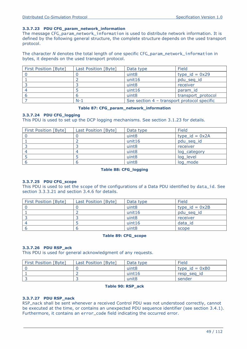
Distributed Co-Simulation Protocol Specification Version 1.0
49 / 112
3.3.7.23 PDU CFG_param_network_information
The message CFG_param_network_information is used to distribute network information. It is
defined by the following general structure, the complete structure depends on the used transport
protocol.
The character N denotes the total length of one specific CFG_param_network_information in
bytes, it depends on the used transport protocol.
First Position [Byte] Last Position [Byte] Data type Field
0 0 uint8 type_id = 0x29
1 2 unit16 pdu_seq_id
3 3 uint8 receiver
4 5 uint16 param_id
6 6 uint8 transport_protocol
7 N-1 See section 4 – transport protocol specific
Table 87: CFG_param_network_information
3.3.7.24 PDU CFG_logging
This PDU is used to set up the DCP logging mechanisms. See section 3.1.23 for details.
First Position [Byte] Last Position [Byte] Data type Field
0 0 uint8 type_id = 0x2A
1 2 unit16 pdu_seq_id
3 3 uint8 receiver
4 4 uint8 log_category
5 5 uint8 log_level
6 6 uint8 log_mode
Table 88: CFG_logging
3.3.7.25 PDU CFG_scope
This PDU is used to set the scope of the configurations of a Data PDU identified by data_id. See
section 3.3.3.21 and section 3.4.6 for details.
First Position [Byte] Last Position [Byte] Data type Field
0 0 uint8 type_id = 0x2B
1 2 unit16 pdu_seq_id
3 3 uint8 receiver
4 5 uint16 data_id
6 6 uint8 scope
Table 89: CFG_scope
3.3.7.26 PDU RSP_ack
This PDU is used for general acknowledgment of any requests.
First Position [Byte] Last Position [Byte] Data type Field
0 0 uint8 type_id = 0xB0
1 2 uint16 resp_seq_id
3 3 unit8 sender
Table 90: RSP_ack
3.3.7.27 PDU RSP_nack
RSP_nack shall be sent whenever a received Control PDU was not understood correctly, cannot
be executed at the time, or contains an unexpected PDU sequence identifier (see section 3.4.1).
Furthermore, it contains an error_code field indicating the occurred error.
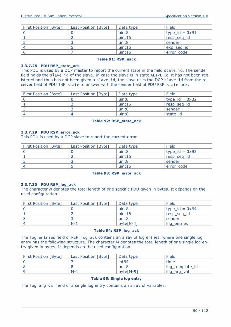
Distributed Co-Simulation Protocol Specification Version 1.0
50 / 112
First Position [Byte] Last Position [Byte] Data type Field
0 0 uint8 type_id = 0xB1
1 2 uint16 resp_seq_id
3 3 unit8 sender
4 5 uint16 exp_seq_id
6 7 uint16 error_code
Table 91: RSP_nack
3.3.7.28 PDU RSP_state_ack
This PDU is used by a DCP master to report the current state in the field state_id. The sender
field holds the slave id of the slave. In case the slave is in state ALIVE i.e. it has not been reg-
istered and thus has not been given a slave id, the slave uses the DCP slave id from the re-
ceiver field of PDU INF_state to answer with the sender field of PDU RSP_state_ack.
First Position [Byte] Last Position [Byte] Data type Field
0 0 uint8 type_id = 0xB2
1 2 uint16 resp_seq_id
3 3 unit8 sender
4 4 uint8 state_id
Table 92: RSP_state_ack
3.3.7.29 PDU RSP_error_ack
This PDU is used by a DCP slave to report the current error.
First Position [Byte] Last Position [Byte] Data type Field
0 0 uint8 type_id = 0xB3
1 2 uint16 resp_seq_id
3 3 unit8 sender
4 5 uint16 error_code
Table 93: RSP_error_ack
3.3.7.30 PDU RSP_log_ack
The character N denotes the total length of one specific PDU given in bytes. It depends on the
used configuration.
First Position [Byte] Last Position [Byte] Data type Field
0 0 uint8 type_id = 0xB4
1 2 uint16 resp_seq_id
3 3 unit8 sender
4 N-1 byte[N-4] log_entries
Table 94: RSP_log_ack
The log_entries field of RSP_log_ack contains an array of log entries, where one single log
entry has the following structure. The character M denotes the total length of one single log en-
try given in bytes. It depends on the used configuration.
First Position [Byte] Last Position [Byte] Data type Field
0 7 int64 time
8 8 unit8 log_template_id
9 M-1 byte[M-9] log_arg_val
Table 95: Single log entry
The log_arg_val field of a single log entry contains an array of variables.
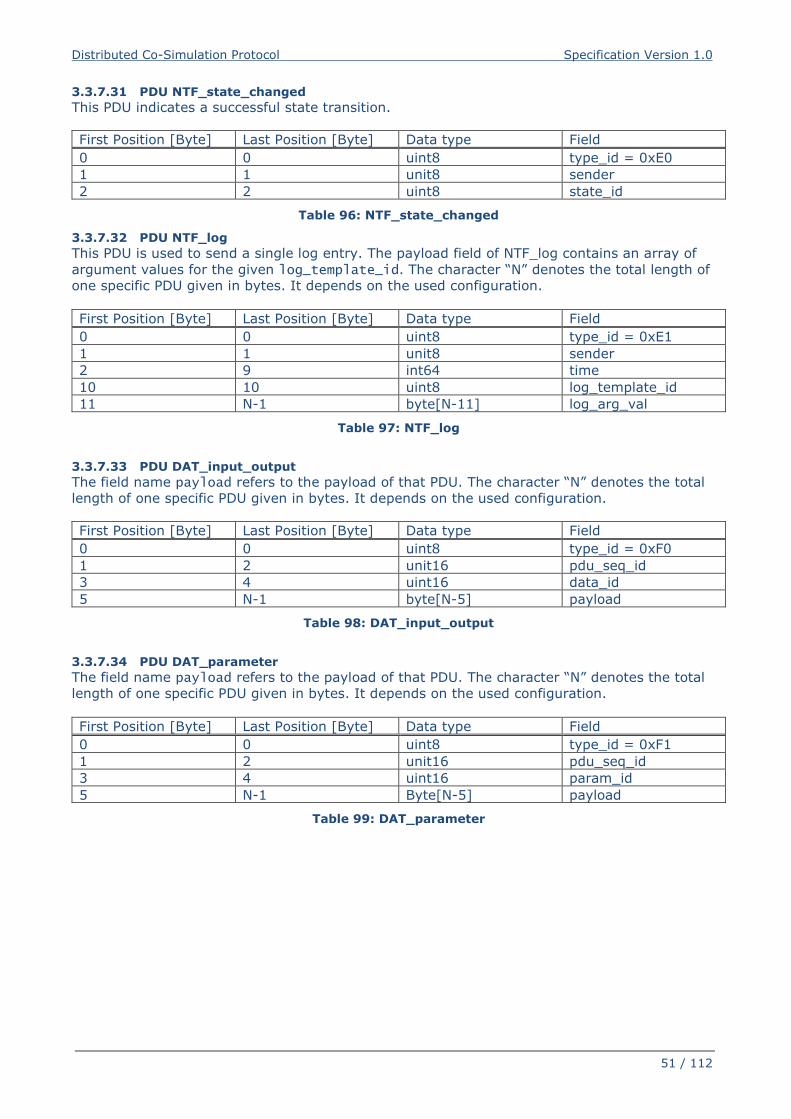
Distributed Co-Simulation Protocol Specification Version 1.0
51 / 112
3.3.7.31 PDU NTF_state_changed
This PDU indicates a successful state transition.
First Position [Byte] Last Position [Byte] Data type Field
0 0 uint8 type_id = 0xE0
1 1 unit8 sender
2 2 uint8 state_id
Table 96: NTF_state_changed
3.3.7.32 PDU NTF_log
This PDU is used to send a single log entry. The payload field of NTF_log contains an array of
argument values for the given log_template_id. The character “N” denotes the total length of
one specific PDU given in bytes. It depends on the used configuration.
First Position [Byte] Last Position [Byte] Data type Field
0 0 uint8 type_id = 0xE1
1 1 unit8 sender
2 9 int64 time
10 10 uint8 log_template_id
11 N-1 byte[N-11] log_arg_val
Table 97: NTF_log
3.3.7.33 PDU DAT_input_output
The field name payload refers to the payload of that PDU. The character “N” denotes the total
length of one specific PDU given in bytes. It depends on the used configuration.
First Position [Byte] Last Position [Byte] Data type Field
0 0 uint8 type_id = 0xF0
1 2 unit16 pdu_seq_id
3 4 uint16 data_id
5 N-1 byte[N-5] payload
Table 98: DAT_input_output
3.3.7.34 PDU DAT_parameter
The field name payload refers to the payload of that PDU. The character “N” denotes the total
length of one specific PDU given in bytes. It depends on the used configuration.
First Position [Byte] Last Position [Byte] Data type Field
0 0 uint8 type_id = 0xF1
1 2 unit16 pdu_seq_id
3 4 uint16 param_id
5 N-1 Byte[N-5] payload
Table 99: DAT_parameter
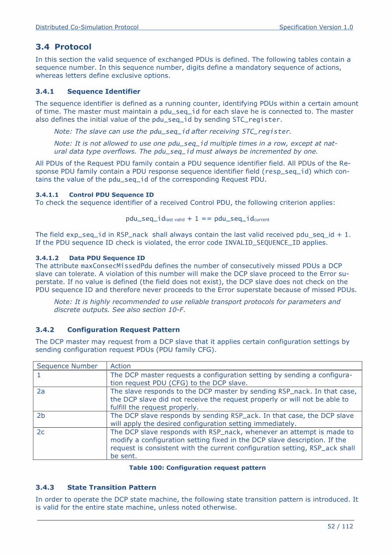
Distributed Co-Simulation Protocol Specification Version 1.0
52 / 112
3.4 Protocol
In this section the valid sequence of exchanged PDUs is defined. The following tables contain a
sequence number. In this sequence number, digits define a mandatory sequence of actions,
whereas letters define exclusive options.
3.4.1 Sequence Identifier
The sequence identifier is defined as a running counter, identifying PDUs within a certain amount
of time. The master must maintain a pdu_seq_id for each slave he is connected to. The master
also defines the initial value of the pdu_seq_id by sending STC_register.
Note: The slave can use the pdu_seq_id after receiving STC_register.
Note: It is not allowed to use one pdu_seq_id multiple times in a row, except at nat-
ural data type overflows. The pdu_seq_id must always be incremented by one.
All PDUs of the Request PDU family contain a PDU sequence identifier field. All PDUs of the Re-
sponse PDU family contain a PDU response sequence identifier field (resp_seq_id) which con-
tains the value of the pdu_seq_id of the corresponding Request PDU.
3.4.1.1 Control PDU Sequence ID
To check the sequence identifier of a received Control PDU, the following criterion applies:
pdu_seq_idlast valid + 1 == pdu_seq_idcurrent
The field exp_seq_id in RSP_nack shall always contain the last valid received pdu_seq_id + 1.
If the PDU sequence ID check is violated, the error code INVALID_SEQUENCE_ID applies.
3.4.1.2 Data PDU Sequence ID
The attribute maxConsecMissedPdu defines the number of consecutively missed PDUs a DCP
slave can tolerate. A violation of this number will make the DCP slave proceed to the Error su-
perstate. If no value is defined (the field does not exist), the DCP slave does not check on the
PDU sequence ID and therefore never proceeds to the Error superstate because of missed PDUs.
Note: It is highly recommended to use reliable transport protocols for parameters and
discrete outputs. See also section 10-F.
3.4.2 Configuration Request Pattern
The DCP master may request from a DCP slave that it applies certain configuration settings by
sending configuration request PDUs (PDU family CFG).
Sequence Number Action
1 The DCP master requests a configuration setting by sending a configura-
tion request PDU (CFG) to the DCP slave.
2a The slave responds to the DCP master by sending RSP_nack. In that case,
the DCP slave did not receive the request properly or will not be able to
fulfill the request properly.
2b The DCP slave responds by sending RSP_ack. In that case, the DCP slave
will apply the desired configuration setting immediately.
2c The DCP slave responds with RSP_nack, whenever an attempt is made to
modify a configuration setting fixed in the DCP slave description. If the
request is consistent with the current configuration setting, RSP_ack shall
be sent.
Table 100: Configuration request pattern
3.4.3 State Transition Pattern
In order to operate the DCP state machine, the following state transition pattern is introduced. It
is valid for the entire state machine, unless noted otherwise.
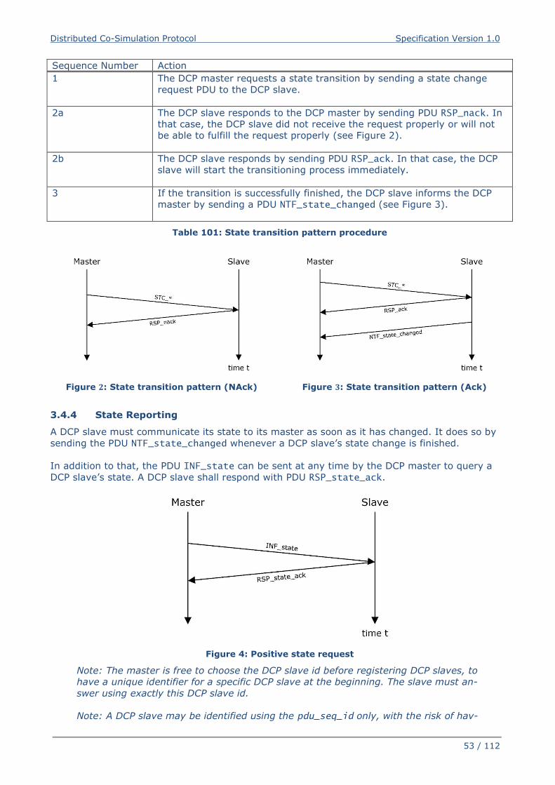
Distributed Co-Simulation Protocol Specification Version 1.0
53 / 112
Sequence Number Action
1 The DCP master requests a state transition by sending a state change
request PDU to the DCP slave.
2a The DCP slave responds to the DCP master by sending PDU RSP_nack. In
that case, the DCP slave did not receive the request properly or will not
be able to fulfill the request properly (see Figure 2).
2b The DCP slave responds by sending PDU RSP_ack. In that case, the DCP
slave will start the transitioning process immediately.
3 If the transition is successfully finished, the DCP slave informs the DCP
master by sending a PDU NTF_state_changed (see Figure 3).
Table 101: State transition pattern procedure
Figure 2: State transition pattern (NAck) Figure 3: State transition pattern (Ack)
3.4.4 State Reporting
A DCP slave must communicate its state to its master as soon as it has changed. It does so by
sending the PDU NTF_state_changed whenever a DCP slave’s state change is finished.
In addition to that, the PDU INF_state can be sent at any time by the DCP master to query a
DCP slave’s state. A DCP slave shall respond with PDU RSP_state_ack.
Figure 4: Positive state request
Note: The master is free to choose the DCP slave id before registering DCP slaves, to
have a unique identifier for a specific DCP slave at the beginning. The slave must an-
swer using exactly this DCP slave id.
Note: A DCP slave may be identified using the pdu_seq_id only, with the risk of hav-
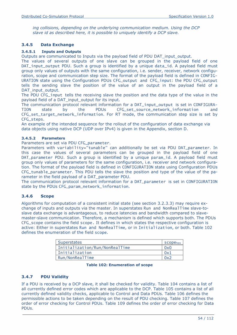
Distributed Co-Simulation Protocol Specification Version 1.0
54 / 112
ing collisions, depending on the underlying communication medium. Using the DCP
slave id as described here, it is possible to uniquely identify a DCP slave.
3.4.5 Data Exchange
3.4.5.1 Inputs and Outputs
Outputs are communicated to Inputs via the payload field of PDU DAT_input_output.
The values of several outputs of one slave can be grouped in the payload field of one
DAT_input_output PDU. Such a group is identified by a unique data_id. A payload field must
group only values of outputs with the same configuration, i.e. sender, receiver, network configu-
ration, scope and communication step size. The format of the payload field is defined in CONFIG-URATION state using the Configuration PDUs CFG_output and CFG_input: the PDU CFG_output tells the sending slave the position of the value of an output in the payload field of a
DAT_input_output.
The PDU CFG_input tells the receiving slave the position and the data type of the value in the
payload field of a DAT_input_output for its input.
The communication protocol relevant information for a DAT_input_output is set in CONFIGURA-TION state by the PDUs CFG_set_source_network_information and CFG_set_target_network_information. For RT mode, the communication step size is set by
CFG_steps.
An example of the intended sequence for the rollout of the configuration of data exchange via
data objects using native DCP (UDP over IPv4) is given in the Appendix, section D.
3.4.5.2 Parameters
Parameters are set via PDU CFG_parameter.
Parameters with variability=”tunable” can additionally be set via PDU DAT_parameter. In
this case the values of several parameters can be grouped in the payload field of one
DAT_parameter PDU. Such a group is identified by a unique param_id. A payload field must
group only values of parameters for the same configuration, i.e. receiver and network configura-
tion. The format of the payload field is defined in CONFIGURATION state using Configuration PDUs
CFG_tunable_parameter. This PDU tells the slave the position and type of the value of the pa-
rameter in the field payload of a DAT_parameter PDU.
The communication protocol relevant information for a DAT_parameter is set in CONFIGURATION
state by the PDUs CFG_param_network_information.
3.4.6 Scope
Algorithms for computation of a consistent initial state (see section 3.2.3.3) may require ex-
change of inputs and outputs via the master. In superstates Run and NonRealTime slave-to-
slave data exchange is advantageous, to reduce latencies and bandwidth compared to slave-
master-slave communication. Therefore, a mechanism is defined which supports both. The PDUs
CFG_scope contains the field scope. It defines in which states the respective configuration is
active: Either in superstates Run and NonRealTime, or in Initialization, or both. Table 102
defines the enumeration of the field scope.
Superstates scopehex
Initialization/Run/NonRealTime 0x0
Initialization 0x1
Run/NonRealTime 0x2
Table 102: Enumeration of scope
3.4.7 PDU Validity
If a PDU is received by a DCP slave, it shall be checked for validity. Table 104 contains a list of
all currently defined error codes which are applicable to the DCP. Table 105 contains a list of all
currently defined validity checks, applicable to Control and Data PDUs. Table 106 defines the
permissible actions to be taken depending on the result of PDU checking. Table 107 defines the
order of error checking for Control PDUs. Table 109 defines the order of error checking for Data
PDUs.
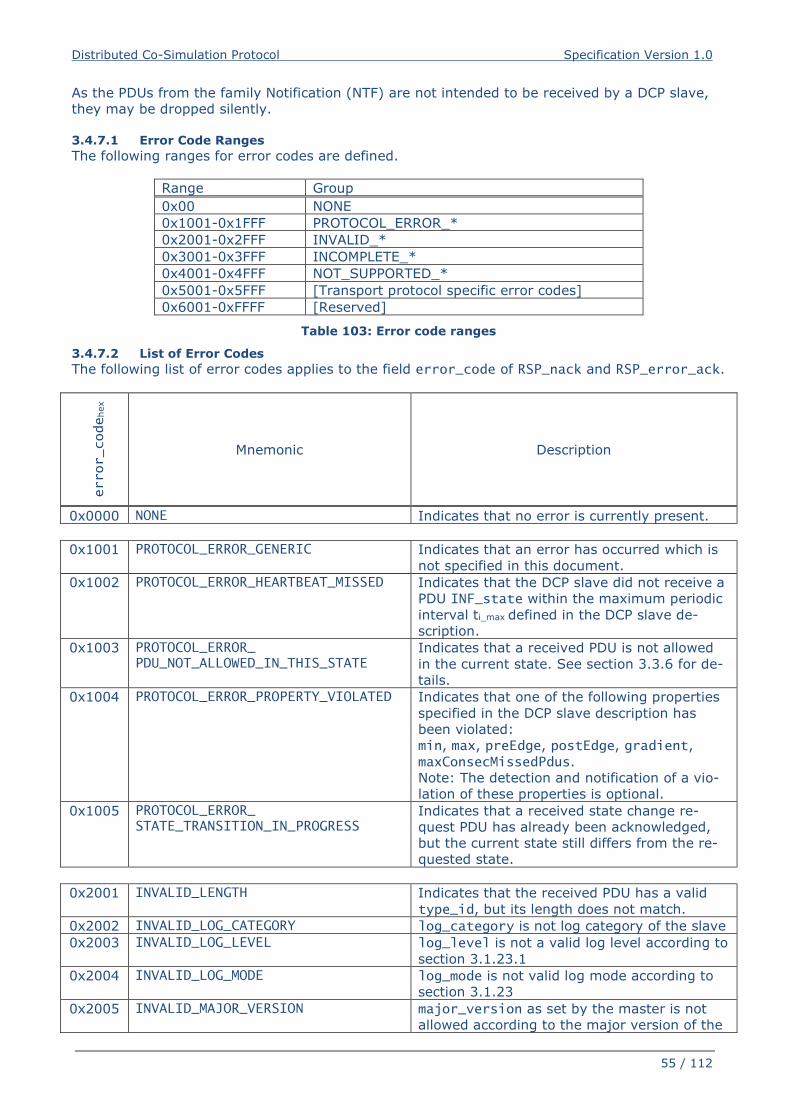
Distributed Co-Simulation Protocol Specification Version 1.0
55 / 112
As the PDUs from the family Notification (NTF) are not intended to be received by a DCP slave,
they may be dropped silently.
3.4.7.1 Error Code Ranges
The following ranges for error codes are defined.
Range Group
0x00 NONE
0x1001-0x1FFF PROTOCOL_ERROR_*
0x2001-0x2FFF INVALID_*
0x3001-0x3FFF INCOMPLETE_*
0x4001-0x4FFF NOT_SUPPORTED_*
0x5001-0x5FFF [Transport protocol specific error codes]
0x6001-0xFFFF [Reserved]
Table 103: Error code ranges
3.4.7.2 List of Error Codes
The following list of error codes applies to the field error_code of RSP_nack and RSP_error_ack.
error_code
hex
Mnemonic Description
0x0000 NONE Indicates that no error is currently present.
0x1001 PROTOCOL_ERROR_GENERIC Indicates that an error has occurred which is
not specified in this document.
0x1002 PROTOCOL_ERROR_HEARTBEAT_MISSED Indicates that the DCP slave did not receive a
PDU INF_state within the maximum periodic
interval ti_max defined in the DCP slave de-
scription.
0x1003 PROTOCOL_ERROR_ PDU_NOT_ALLOWED_IN_THIS_STATE
Indicates that a received PDU is not allowed
in the current state. See section 3.3.6 for de-
tails.
0x1004 PROTOCOL_ERROR_PROPERTY_VIOLATED Indicates that one of the following properties
specified in the DCP slave description has
been violated:
min, max, preEdge, postEdge, gradient,
maxConsecMissedPdus.
Note: The detection and notification of a vio-
lation of these properties is optional.
0x1005 PROTOCOL_ERROR_ STATE_TRANSITION_IN_PROGRESS
Indicates that a received state change re-
quest PDU has already been acknowledged,
but the current state still differs from the re-
quested state.
0x2001 INVALID_LENGTH Indicates that the received PDU has a valid
type_id, but its length does not match.
0x2002 INVALID_LOG_CATEGORY log_category is not log category of the slave
0x2003 INVALID_LOG_LEVEL log_level is not a valid log level according to
section 3.1.23.1
0x2004 INVALID_LOG_MODE log_mode is not valid log mode according to
section 3.1.23
0x2005 INVALID_MAJOR_VERSION major_version as set by the master is not
allowed according to the major version of the
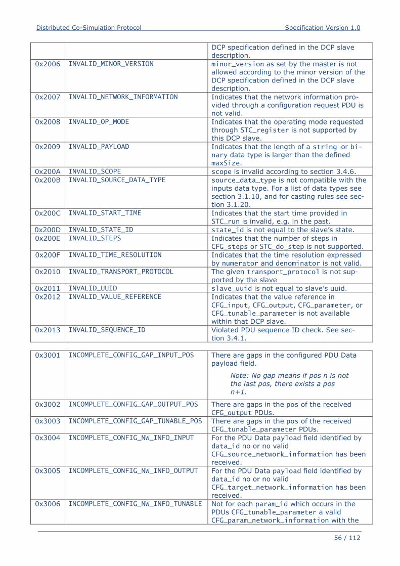
Distributed Co-Simulation Protocol Specification Version 1.0
56 / 112
DCP specification defined in the DCP slave
description.
0x2006 INVALID_MINOR_VERSION minor_version as set by the master is not
allowed according to the minor version of the
DCP specification defined in the DCP slave
description.
0x2007 INVALID_NETWORK_INFORMATION Indicates that the network information pro-
vided through a configuration request PDU is
not valid.
0x2008 INVALID_OP_MODE Indicates that the operating mode requested
through STC_register is not supported by
this DCP slave.
0x2009 INVALID_PAYLOAD Indicates that the length of a string or bi-nary data type is larger than the defined
maxSize.
0x200A INVALID_SCOPE scope is invalid according to section 3.4.6.
0x200B INVALID_SOURCE_DATA_TYPE source_data_type is not compatible with the
inputs data type. For a list of data types see
section 3.1.10, and for casting rules see sec-
tion 3.1.20.
0x200C INVALID_START_TIME
Indicates that the start time provided in
STC_run is invalid, e.g. in the past.
0x200D INVALID_STATE_ID state_id is not equal to the slave’s state.
0x200E INVALID_STEPS Indicates that the number of steps in
CFG_steps or STC_do_step is not supported.
0x200F INVALID_TIME_RESOLUTION Indicates that the time resolution expressed
by numerator and denominator is not valid.
0x2010 INVALID_TRANSPORT_PROTOCOL The given transport_protocol is not sup-
ported by the slave
0x2011 INVALID_UUID slave_uuid is not equal to slave’s uuid.
0x2012 INVALID_VALUE_REFERENCE Indicates that the value reference in
CFG_input, CFG_output, CFG_parameter, or
CFG_tunable_parameter is not available
within that DCP slave.
0x2013 INVALID_SEQUENCE_ID Violated PDU sequence ID check. See sec-
tion 3.4.1.
0x3001 INCOMPLETE_CONFIG_GAP_INPUT_POS There are gaps in the configured PDU Data
payload field.
Note: No gap means if pos n is not
the last pos, there exists a pos
n+1.
0x3002 INCOMPLETE_CONFIG_GAP_OUTPUT_POS There are gaps in the pos of the received
CFG_output PDUs.
0x3003 INCOMPLETE_CONFIG_GAP_TUNABLE_POS There are gaps in the pos of the received
CFG_tunable_parameter PDUs.
0x3004 INCOMPLETE_CONFIG_NW_INFO_INPUT For the PDU Data payload field identified by
data_id no or no valid
CFG_source_network_information has been
received.
0x3005 INCOMPLETE_CONFIG_NW_INFO_OUTPUT For the PDU Data payload field identified by
data_id no or no valid
CFG_target_network_information has been
received.
0x3006 INCOMPLETE_CONFIG_NW_INFO_TUNABLE Not for each param_id which occurs in the
PDUs CFG_tunable_parameter a valid
CFG_param_network_information with the
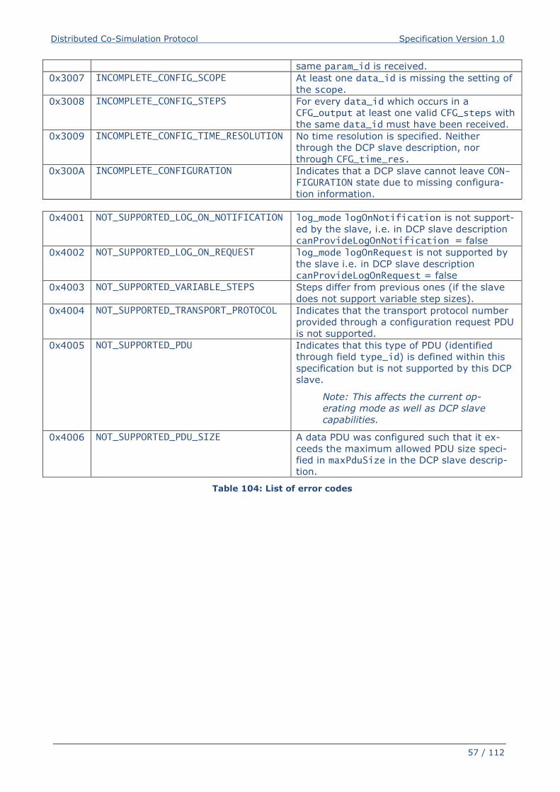
Distributed Co-Simulation Protocol Specification Version 1.0
57 / 112
same param_id is received.
0x3007 INCOMPLETE_CONFIG_SCOPE At least one data_id is missing the setting of
the scope.
0x3008 INCOMPLETE_CONFIG_STEPS For every data_id which occurs in a
CFG_output at least one valid CFG_steps with
the same data_id must have been received.
0x3009 INCOMPLETE_CONFIG_TIME_RESOLUTION No time resolution is specified. Neither
through the DCP slave description, nor
through CFG_time_res.
0x300A INCOMPLETE_CONFIGURATION Indicates that a DCP slave cannot leave CON-FIGURATION state due to missing configura-
tion information.
0x4001 NOT_SUPPORTED_LOG_ON_NOTIFICATION log_mode logOnNotification is not support-
ed by the slave, i.e. in DCP slave description
canProvideLogOnNotification = false
0x4002 NOT_SUPPORTED_LOG_ON_REQUEST log_mode logOnRequest is not supported by
the slave i.e. in DCP slave description
canProvideLogOnRequest = false
0x4003 NOT_SUPPORTED_VARIABLE_STEPS Steps differ from previous ones (if the slave
does not support variable step sizes).
0x4004 NOT_SUPPORTED_TRANSPORT_PROTOCOL Indicates that the transport protocol number
provided through a configuration request PDU
is not supported.
0x4005 NOT_SUPPORTED_PDU Indicates that this type of PDU (identified
through field type_id) is defined within this
specification but is not supported by this DCP
slave.
Note: This affects the current op-
erating mode as well as DCP slave
capabilities.
0x4006 NOT_SUPPORTED_PDU_SIZE A data PDU was configured such that it ex-
ceeds the maximum allowed PDU size speci-
fied in maxPduSize in the DCP slave descrip-
tion.
Table 104: List of error codes
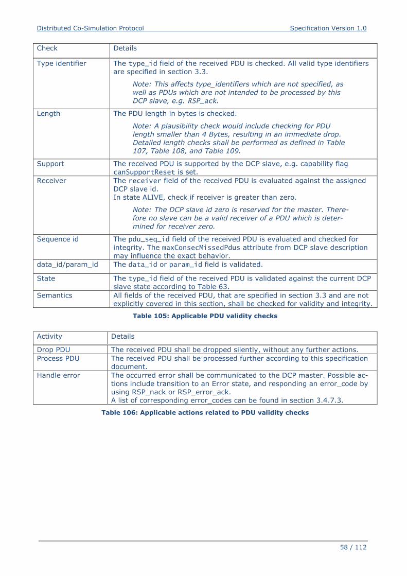
Distributed Co-Simulation Protocol Specification Version 1.0
58 / 112
Check Details
Type identifier The type_id field of the received PDU is checked. All valid type identifiers
are specified in section 3.3.
Note: This affects type_identifiers which are not specified, as
well as PDUs which are not intended to be processed by this
DCP slave, e.g. RSP_ack.
Length The PDU length in bytes is checked.
Note: A plausibility check would include checking for PDU
length smaller than 4 Bytes, resulting in an immediate drop.
Detailed length checks shall be performed as defined in Table
107, Table 108, and Table 109.
Support The received PDU is supported by the DCP slave, e.g. capability flag
canSupportReset is set.
Receiver The receiver field of the received PDU is evaluated against the assigned
DCP slave id.
In state ALIVE, check if receiver is greater than zero.
Note: The DCP slave id zero is reserved for the master. There-
fore no slave can be a valid receiver of a PDU which is deter-
mined for receiver zero.
Sequence id The pdu_seq_id field of the received PDU is evaluated and checked for
integrity. The maxConsecMissedPdus attribute from DCP slave description
may influence the exact behavior.
data_id/param_id The data_id or param_id field is validated.
State The type_id field of the received PDU is validated against the current DCP
slave state according to Table 63.
Semantics All fields of the received PDU, that are specified in section 3.3 and are not
explicitly covered in this section, shall be checked for validity and integrity.
Table 105: Applicable PDU validity checks
Activity Details
Drop PDU The received PDU shall be dropped silently, without any further actions.
Process PDU The received PDU shall be processed further according to this specification
document.
Handle error The occurred error shall be communicated to the DCP master. Possible ac-
tions include transition to an Error state, and responding an error_code by
using RSP_nack or RSP_error_ack.
A list of corresponding error_codes can be found in section 3.4.7.3.
Table 106: Applicable actions related to PDU validity checks
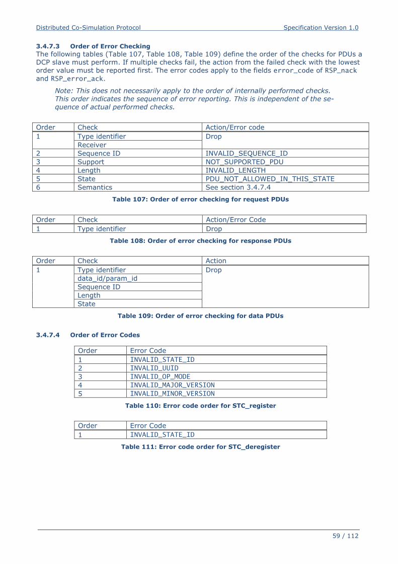
Distributed Co-Simulation Protocol Specification Version 1.0
59 / 112
3.4.7.3 Order of Error Checking
The following tables (Table 107, Table 108, Table 109) define the order of the checks for PDUs a
DCP slave must perform. If multiple checks fail, the action from the failed check with the lowest
order value must be reported first. The error codes apply to the fields error_code of RSP_nack
and RSP_error_ack.
Note: This does not necessarily apply to the order of internally performed checks.
This order indicates the sequence of error reporting. This is independent of the se-
quence of actual performed checks.
Order Check Action/Error code
1 Type identifier Drop
Receiver
2 Sequence ID INVALID_SEQUENCE_ID
3 Support NOT_SUPPORTED_PDU
4 Length INVALID_LENGTH
5 State PDU_NOT_ALLOWED_IN_THIS_STATE
6 Semantics See section 3.4.7.4
Table 107: Order of error checking for request PDUs
Order Check Action/Error Code
1 Type identifier Drop
Table 108: Order of error checking for response PDUs
Order Check Action
1 Type identifier Drop
data_id/param_id
Sequence ID
Length
State
Table 109: Order of error checking for data PDUs
3.4.7.4 Order of Error Codes
Order Error Code
1 INVALID_STATE_ID
2 INVALID_UUID
3 INVALID_OP_MODE
4 INVALID_MAJOR_VERSION
5 INVALID_MINOR_VERSION
Table 110: Error code order for STC_register
Order Error Code
1 INVALID_STATE_ID
Table 111: Error code order for STC_deregister
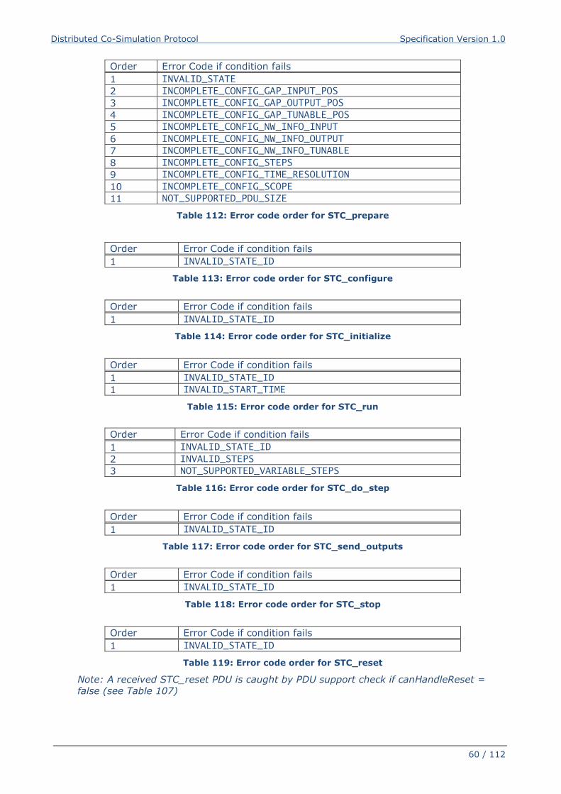
Distributed Co-Simulation Protocol Specification Version 1.0
60 / 112
Order Error Code if condition fails
1 INVALID_STATE
2 INCOMPLETE_CONFIG_GAP_INPUT_POS
3 INCOMPLETE_CONFIG_GAP_OUTPUT_POS
4 INCOMPLETE_CONFIG_GAP_TUNABLE_POS
5 INCOMPLETE_CONFIG_NW_INFO_INPUT
6 INCOMPLETE_CONFIG_NW_INFO_OUTPUT
7 INCOMPLETE_CONFIG_NW_INFO_TUNABLE
8 INCOMPLETE_CONFIG_STEPS
9 INCOMPLETE_CONFIG_TIME_RESOLUTION
10 INCOMPLETE_CONFIG_SCOPE
11 NOT_SUPPORTED_PDU_SIZE
Table 112: Error code order for STC_prepare
Order Error Code if condition fails
1 INVALID_STATE_ID
Table 113: Error code order for STC_configure
Order Error Code if condition fails
1 INVALID_STATE_ID
Table 114: Error code order for STC_initialize
Order Error Code if condition fails
1 INVALID_STATE_ID
1 INVALID_START_TIME
Table 115: Error code order for STC_run
Order Error Code if condition fails
1 INVALID_STATE_ID
2 INVALID_STEPS
3 NOT_SUPPORTED_VARIABLE_STEPS
Table 116: Error code order for STC_do_step
Order Error Code if condition fails
1 INVALID_STATE_ID
Table 117: Error code order for STC_send_outputs
Order Error Code if condition fails
1 INVALID_STATE_ID
Table 118: Error code order for STC_stop
Order Error Code if condition fails
1 INVALID_STATE_ID
Table 119: Error code order for STC_reset
Note: A received STC_reset PDU is caught by PDU support check if canHandleReset =
false (see Table 107)
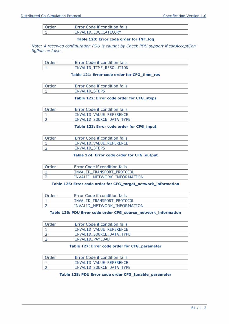
Distributed Co-Simulation Protocol Specification Version 1.0
61 / 112
Order Error Code if condition fails
1 INVALID_LOG_CATEGORY
Table 120: Error code order for INF_log
Note: A received configuration PDU is caught by Check PDU support if canAcceptCon-
figPdus = false.
Order Error Code if condition fails
1 INVALID_TIME_RESOLUTION
Table 121: Error code order for CFG_time_res
Order Error Code if condition fails
1 INVALID_STEPS
Table 122: Error code order for CFG_steps
Order Error Code if condition fails
1 INVALID_VALUE_REFERENCE
2 INVALID_SOURCE_DATA_TYPE
Table 123: Error code order for CFG_input
Order Error Code if condition fails
1 INVALID_VALUE_REFERENCE
2 INVALID_STEPS
Table 124: Error code order for CFG_output
Order Error Code if condition fails
1 INVALID_TRANSPORT_PROTOCOL
2 INVALID_NETWORK_INFORMATION
Table 125: Error code order for CFG_target_network_information
Order Error Code if condition fails
1 INVALID_TRANSPORT_PROTOCOL
2 INVALID_NETWORK_INFORMATION
Table 126: PDU Error code order CFG_source_network_information
Order Error Code if condition fails
1 INVALID_VALUE_REFERENCE
2 INVALID_SOURCE_DATA_TYPE
3 INVALID_PAYLOAD
Table 127: Error code order for CFG_parameter
Order Error Code if condition fails
1 INVALID_VALUE_REFERENCE
2 INVALID_SOURCE_DATA_TYPE
Table 128: PDU Error code order CFG_tunable_parameter
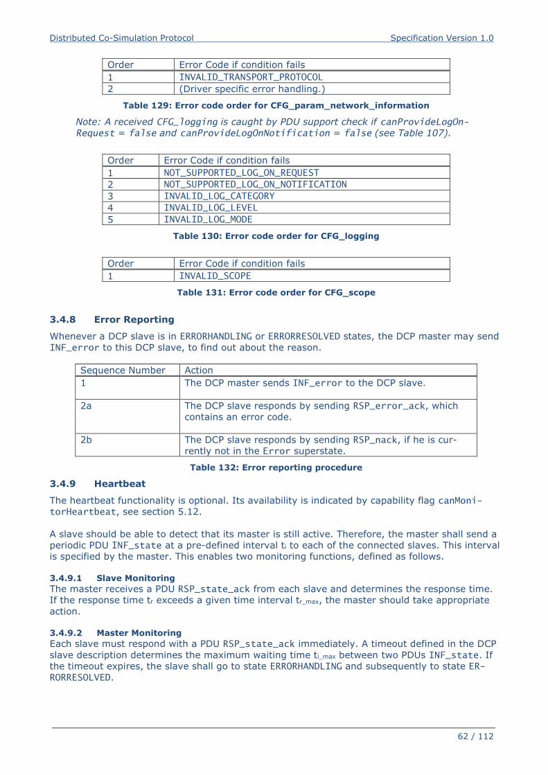
Distributed Co-Simulation Protocol Specification Version 1.0
62 / 112
Order Error Code if condition fails
1 INVALID_TRANSPORT_PROTOCOL
2 (Driver specific error handling.)
Table 129: Error code order for CFG_param_network_information
Note: A received CFG_logging is caught by PDU support check if canProvideLogOn-Request = false and canProvideLogOnNotification = false (see Table 107).
Order Error Code if condition fails
1 NOT_SUPPORTED_LOG_ON_REQUEST
2 NOT_SUPPORTED_LOG_ON_NOTIFICATION
3 INVALID_LOG_CATEGORY
4 INVALID_LOG_LEVEL
5 INVALID_LOG_MODE
Table 130: Error code order for CFG_logging
Order Error Code if condition fails
1 INVALID_SCOPE
Table 131: Error code order for CFG_scope
3.4.8 Error Reporting
Whenever a DCP slave is in ERRORHANDLING or ERRORRESOLVED states, the DCP master may send
INF_error to this DCP slave, to find out about the reason.
Sequence Number Action
1 The DCP master sends INF_error to the DCP slave.
2a The DCP slave responds by sending RSP_error_ack, which
contains an error code.
2b The DCP slave responds by sending RSP_nack, if he is cur-
rently not in the Error superstate.
Table 132: Error reporting procedure
3.4.9 Heartbeat
The heartbeat functionality is optional. Its availability is indicated by capability flag canMoni-torHeartbeat, see section 5.12.
A slave should be able to detect that its master is still active. Therefore, the master shall send a
periodic PDU INF_state at a pre-defined interval ti to each of the connected slaves. This interval
is specified by the master. This enables two monitoring functions, defined as follows.
3.4.9.1 Slave Monitoring
The master receives a PDU RSP_state_ack from each slave and determines the response time.
If the response time tr exceeds a given time interval tr_max, the master should take appropriate
action.
3.4.9.2 Master Monitoring
Each slave must respond with a PDU RSP_state_ack immediately. A timeout defined in the DCP
slave description determines the maximum waiting time ti_max between two PDUs INF_state. If
the timeout expires, the slave shall go to state ERRORHANDLING and subsequently to state ER-RORRESOLVED.
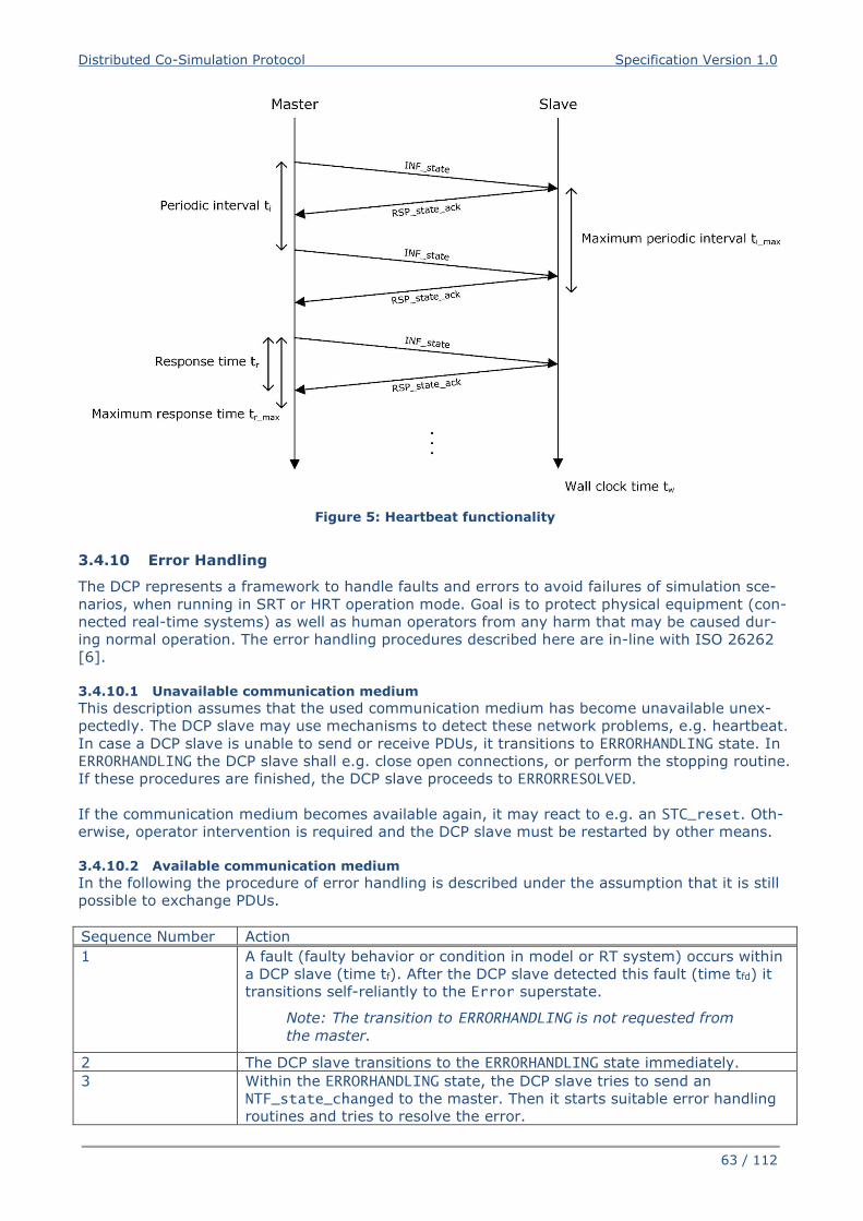
Distributed Co-Simulation Protocol Specification Version 1.0
63 / 112
Figure 5: Heartbeat functionality
3.4.10 Error Handling
The DCP represents a framework to handle faults and errors to avoid failures of simulation sce-
narios, when running in SRT or HRT operation mode. Goal is to protect physical equipment (con-
nected real-time systems) as well as human operators from any harm that may be caused dur-
ing normal operation. The error handling procedures described here are in-line with ISO 26262
[6].
3.4.10.1 Unavailable communication medium
This description assumes that the used communication medium has become unavailable unex-
pectedly. The DCP slave may use mechanisms to detect these network problems, e.g. heartbeat.
In case a DCP slave is unable to send or receive PDUs, it transitions to ERRORHANDLING state. In
ERRORHANDLING the DCP slave shall e.g. close open connections, or perform the stopping routine.
If these procedures are finished, the DCP slave proceeds to ERRORRESOLVED.
If the communication medium becomes available again, it may react to e.g. an STC_reset. Oth-
erwise, operator intervention is required and the DCP slave must be restarted by other means.
3.4.10.2 Available communication medium
In the following the procedure of error handling is described under the assumption that it is still
possible to exchange PDUs.
Sequence Number Action
1 A fault (faulty behavior or condition in model or RT system) occurs within
a DCP slave (time tf). After the DCP slave detected this fault (time tfd) it
transitions self-reliantly to the Error superstate.
Note: The transition to ERRORHANDLING is not requested from
the master.
2 The DCP slave transitions to the ERRORHANDLING state immediately.
3 Within the ERRORHANDLING state, the DCP slave tries to send an
NTF_state_changed to the master. Then it starts suitable error handling
routines and tries to resolve the error.
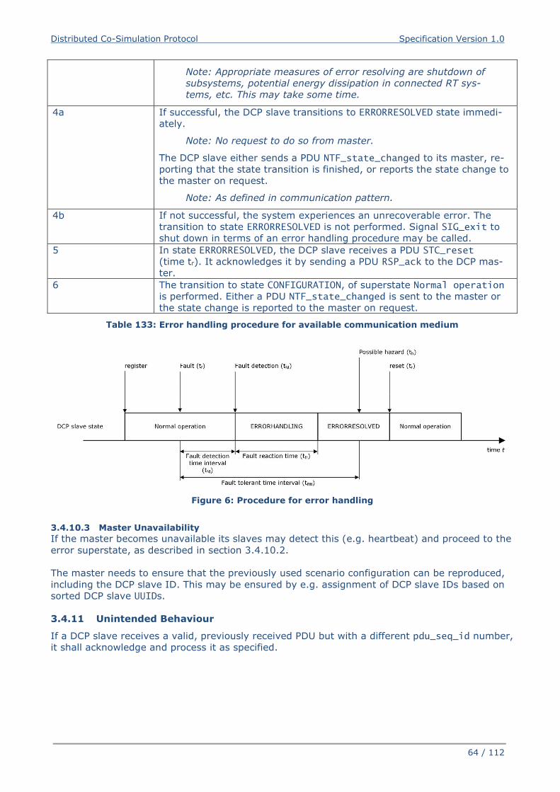
Distributed Co-Simulation Protocol Specification Version 1.0
64 / 112
Note: Appropriate measures of error resolving are shutdown of
subsystems, potential energy dissipation in connected RT sys-
tems, etc. This may take some time.
4a If successful, the DCP slave transitions to ERRORRESOLVED state immedi-
ately.
Note: No request to do so from master.
The DCP slave either sends a PDU NTF_state_changed to its master, re-
porting that the state transition is finished, or reports the state change to
the master on request.
Note: As defined in communication pattern.
4b If not successful, the system experiences an unrecoverable error. The
transition to state ERRORRESOLVED is not performed. Signal SIG_exit to
shut down in terms of an error handling procedure may be called.
5 In state ERRORRESOLVED, the DCP slave receives a PDU STC_reset
(time tr). It acknowledges it by sending a PDU RSP_ack to the DCP mas-
ter.
6 The transition to state CONFIGURATION, of superstate Normal operation
is performed. Either a PDU NTF_state_changed is sent to the master or
the state change is reported to the master on request.
Table 133: Error handling procedure for available communication medium
Figure 6: Procedure for error handling
3.4.10.3 Master Unavailability
If the master becomes unavailable its slaves may detect this (e.g. heartbeat) and proceed to the
error superstate, as described in section 3.4.10.2.
The master needs to ensure that the previously used scenario configuration can be reproduced,
including the DCP slave ID. This may be ensured by e.g. assignment of DCP slave IDs based on
sorted DCP slave UUIDs.
3.4.11 Unintended Behaviour
If a DCP slave receives a valid, previously received PDU but with a different pdu_seq_id number,
it shall acknowledge and process it as specified.
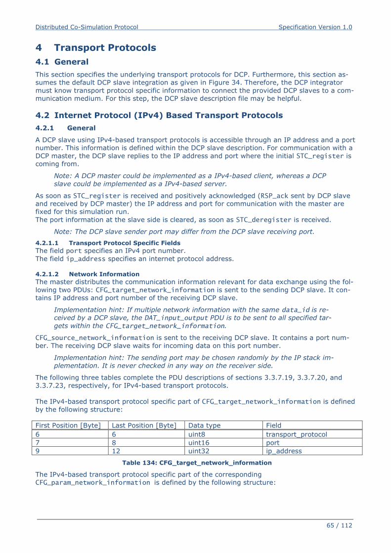
Distributed Co-Simulation Protocol Specification Version 1.0
65 / 112
4 Transport Protocols
4.1 General
This section specifies the underlying transport protocols for DCP. Furthermore, this section as-
sumes the default DCP slave integration as given in Figure 34. Therefore, the DCP integrator
must know transport protocol specific information to connect the provided DCP slaves to a com-
munication medium. For this step, the DCP slave description file may be helpful.
4.2 Internet Protocol (IPv4) Based Transport Protocols
4.2.1 General
A DCP slave using IPv4-based transport protocols is accessible through an IP address and a port
number. This information is defined within the DCP slave description. For communication with a
DCP master, the DCP slave replies to the IP address and port where the initial STC_register is
coming from.
Note: A DCP master could be implemented as a IPv4-based client, whereas a DCP
slave could be implemented as a IPv4-based server.
As soon as STC_register is received and positively acknowledged (RSP_ack sent by DCP slave
and received by DCP master) the IP address and port for communication with the master are
fixed for this simulation run.
The port information at the slave side is cleared, as soon as STC_deregister is received.
Note: The DCP slave sender port may differ from the DCP slave receiving port.
4.2.1.1 Transport Protocol Specific Fields
The field port specifies an IPv4 port number.
The field ip_address specifies an internet protocol address.
4.2.1.2 Network Information
The master distributes the communication information relevant for data exchange using the fol-
lowing two PDUs: CFG_target_network_information is sent to the sending DCP slave. It con-
tains IP address and port number of the receiving DCP slave.
Implementation hint: If multiple network information with the same data_id is re-
ceived by a DCP slave, the DAT_input_output PDU is to be sent to all specified tar-
gets within the CFG_target_network_information.
CFG_source_network_information is sent to the receiving DCP slave. It contains a port num-
ber. The receiving DCP slave waits for incoming data on this port number.
Implementation hint: The sending port may be chosen randomly by the IP stack im-
plementation. It is never checked in any way on the receiver side.
The following three tables complete the PDU descriptions of sections 3.3.7.19, 3.3.7.20, and
3.3.7.23, respectively, for IPv4-based transport protocols.
The IPv4-based transport protocol specific part of CFG_target_network_information is defined
by the following structure:
First Position [Byte] Last Position [Byte] Data type Field
6 6 uint8 transport_protocol
7 8 uint16 port
9 12 uint32 ip_address
Table 134: CFG_target_network_information
The IPv4-based transport protocol specific part of the corresponding
CFG_param_network_information is defined by the following structure:
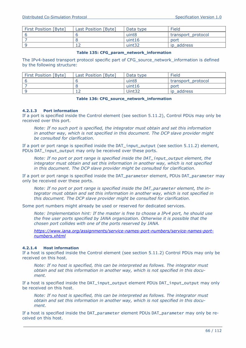
Distributed Co-Simulation Protocol Specification Version 1.0
66 / 112
First Position [Byte] Last Position [Byte] Data type Field
6 6 uint8 transport_protocol
7 8 uint16 port
9 12 uint32 ip_address
Table 135: CFG_param_network_information
The IPv4-based transport protocol specific part of CFG_source_network_information is defined
by the following structure:
First Position [Byte] Last Position [Byte] Data type Field
6 6 uint8 transport_protocol
7 8 uint16 port
9 12 Uint32 ip_address
Table 136: CFG_source_network_information
4.2.1.3 Port information
If a port is specified inside the Control element (see section 5.11.2), Control PDUs may only be
received over this port.
Note: If no such port is specified, the integrator must obtain and set this information
in another way, which is not specified in this document. The DCP slave provider might
be consulted for clarification.
If a port or port range is specified inside the DAT_input_output (see section 5.11.2) element,
PDUs DAT_input_output may only be received over these ports.
Note: If no port or port range is specified inside the DAT_input_output element, the
integrator must obtain and set this information in another way, which is not specified
in this document. The DCP slave provider might be consulted for clarification.
If a port or port range is specified inside the DAT_parameter element, PDUs DAT_parameter may
only be received over these ports.
Note: If no port or port range is specified inside the DAT_parameter element, the in-
tegrator must obtain and set this information in another way, which is not specified in
this document. The DCP slave provider might be consulted for clarification.
Some port numbers might already be used or reserved for dedicated services.
Note: Implementation hint: If the master is free to choose a IPv4 port, he should use
the free user ports specified by IANA organization. Otherwise it is possible that the
chosen port collides with one of the ports reserved by IANA.
https://www.iana.org/assignments/service-names-port-numbers/service-names-port-
numbers.xhtml
4.2.1.4 Host information
If a host is specified inside the Control element (see section 5.11.2) Control PDUs may only be
received on this host.
Note: If no host is specified, this can be interpreted as follows. The integrator must
obtain and set this information in another way, which is not specified in this docu-
ment.
If a host is specified inside the DAT_input_output element PDUs DAT_input_output may only
be received on this host.
Note: If no host is specified, this can be interpreted as follows. The integrator must
obtain and set this information in another way, which is not specified in this docu-
ment.
If a host is specified inside the DAT_parameter element PDUs DAT_parameter may only be re-
ceived on this host.
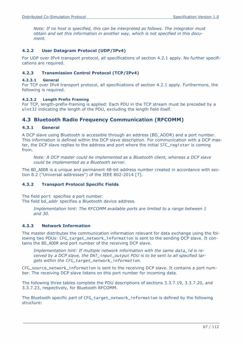
Distributed Co-Simulation Protocol Specification Version 1.0
67 / 112
Note: If no host is specified, this can be interpreted as follows. The integrator must
obtain and set this information in another way, which is not specified in this docu-
ment.
4.2.2 User Datagram Protocol (UDP/IPv4)
For UDP over IPv4 transport protocol, all specifications of section 4.2.1 apply. No further specifi-
cations are required.
4.2.3 Transmission Control Protocol (TCP/IPv4)
4.2.3.1 General
For TCP over IPv4 transport protocol, all specifications of section 4.2.1 apply. Furthermore, the
following is required.
4.2.3.2 Length Prefix Framing
For TCP, length-prefix-framing is applied: Each PDU in the TCP stream must be preceded by a
uint32 indicating the length of the PDU, excluding the length field itself.
4.3 Bluetooth Radio Frequency Communication (RFCOMM)
4.3.1 General
A DCP slave using Bluetooth is accessible through an address (BD_ADDR) and a port number.
This information is defined within the DCP slave description. For communication with a DCP mas-
ter, the DCP slave replies to the address and port where the initial STC_register is coming
from.
Note: A DCP master could be implemented as a Bluetooth client, whereas a DCP slave
could be implemented as a Bluetooth server.
The BD_ADDR is a unique and permanent 48-bit address number created in accordance with sec-
tion 8.2 ("Universal addresses") of the IEEE 802-2014 [7].
4.3.2 Transport Protocol Specific Fields
The field port specifies a port number.
The field bd_addr specifies a Bluetooth device address.
Implementation hint: The RFCOMM available ports are limited to a range between 1
and 30.
4.3.3 Network Information
The master distributes the communication information relevant for data exchange using the fol-
lowing two PDUs: CFG_target_network_information is sent to the sending DCP slave. It con-
tains the BD_ADDR and port number of the receiving DCP slave.
Implementation hint: If multiple network information with the same data_id is re-
ceived by a DCP slave, the DAT_input_output PDU is to be sent to all specified tar-
gets within the CFG_target_network_information.
CFG_source_network_information is sent to the receiving DCP slave. It contains a port num-
ber. The receiving DCP slave listens on this port number for incoming data.
The following three tables complete the PDU descriptions of sections 3.3.7.19, 3.3.7.20, and
3.3.7.23, respectively, for Bluetooth RFCOMM.
The Bluetooth specific part of CFG_target_network_information is defined by the following
structure:
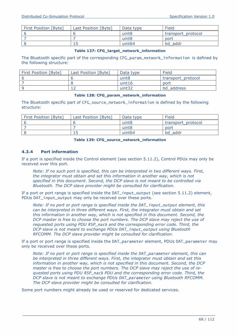
Distributed Co-Simulation Protocol Specification Version 1.0
68 / 112
First Position [Byte] Last Position [Byte] Data type Field
6 6 uint8 transport_protocol
7 7 uint8 port
8 15 uint64 bd_addr
Table 137: CFG_target_network_information
The Bluetooth specific part of the corresponding CFG_param_network_information is defined by
the following structure:
First Position [Byte] Last Position [Byte] Data type Field
6 6 uint8 transport_protocol
7 8 uint16 port
9 12 uint32 bd_address
Table 138: CFG_param_network_information
The Bluetooth specific part of CFG_source_network_information is defined by the following
structure:
First Position [Byte] Last Position [Byte] Data type Field
6 6 uint8 transport_protocol
7 7 uint8 port
8 15 uint64 bd_addr
Table 139: CFG_source_network_information
4.3.4 Port information
If a port is specified inside the Control element (see section 5.11.2), Control PDUs may only be
received over this port.
Note: If no such port is specified, this can be interpreted in two different ways. First,
the integrator must obtain and set this information in another way, which is not
specified in this document. Second, the DCP slave is not meant to be controlled via
Bluetooth. The DCP slave provider might be consulted for clarification.
If a port or port range is specified inside the DAT_input_output (see section 5.11.2) element,
PDUs DAT_input_output may only be received over these ports.
Note: If no port or port range is specified inside the DAT_input_output element, this
can be interpreted in three different ways. First, the integrator must obtain and set
this information in another way, which is not specified in this document. Second, the
DCP master is free to choose the port numbers. The DCP slave may reject the use of
requested ports using PDU RSP_nack and the corresponding error code. Third, the
DCP slave is not meant to exchange PDUs DAT_input_output using Bluetooth
RFCOMM. The DCP slave provider might be consulted for clarification.
If a port or port range is specified inside the DAT_parameter element, PDUs DAT_parameter may
only be received over these ports.
Note: If no port or port range is specified inside the DAT_parameter element, this can
be interpreted in three different ways. First, the integrator must obtain and set this
information in another way, which is not specified in this document. Second, the DCP
master is free to choose the port numbers. The DCP slave may reject the use of re-
quested ports using PDU RSP_nack PDU and the corresponding error code. Third, the
DCP slave is not meant to exchange PDUs DAT_parameter using Bluetooth RFCOMM.
The DCP slave provider might be consulted for clarification.
Some port numbers might already be used or reserved for dedicated services.
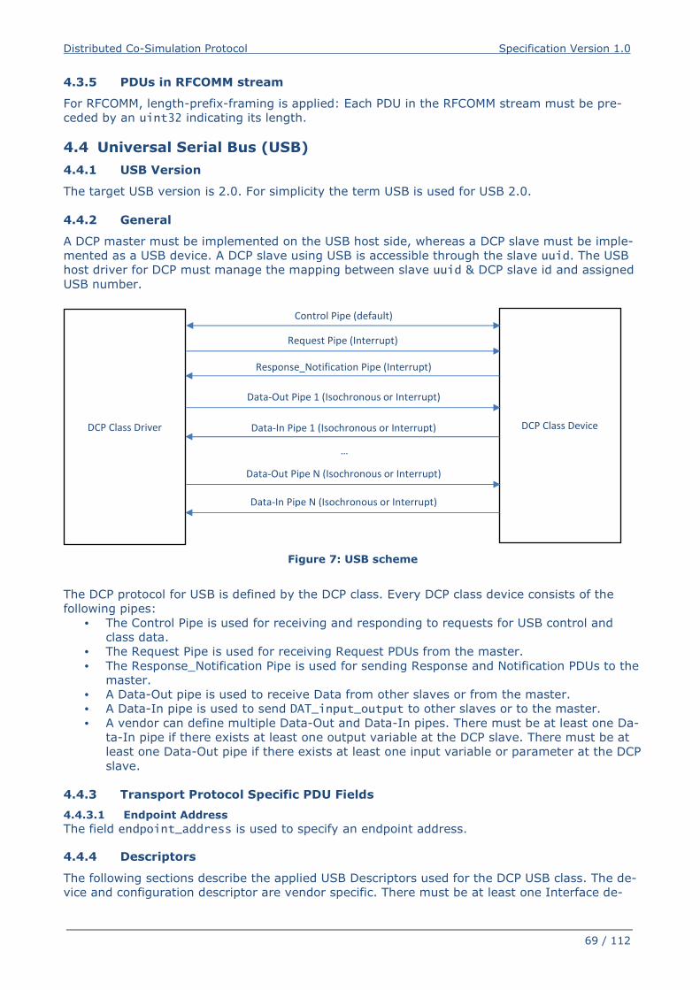
Distributed Co-Simulation Protocol Specification Version 1.0
69 / 112
4.3.5 PDUs in RFCOMM stream
For RFCOMM, length-prefix-framing is applied: Each PDU in the RFCOMM stream must be pre-
ceded by an uint32 indicating its length.
4.4 Universal Serial Bus (USB)
4.4.1 USB Version
The target USB version is 2.0. For simplicity the term USB is used for USB 2.0.
4.4.2 General
A DCP master must be implemented on the USB host side, whereas a DCP slave must be imple-
mented as a USB device. A DCP slave using USB is accessible through the slave uuid. The USB
host driver for DCP must manage the mapping between slave uuid & DCP slave id and assigned
USB number.
Figure 7: USB scheme
The DCP protocol for USB is defined by the DCP class. Every DCP class device consists of the
following pipes:
• The Control Pipe is used for receiving and responding to requests for USB control and
class data.
• The Request Pipe is used for receiving Request PDUs from the master.
• The Response_Notification Pipe is used for sending Response and Notification PDUs to the
master.
• A Data-Out pipe is used to receive Data from other slaves or from the master.
• A Data-In pipe is used to send DAT_input_output to other slaves or to the master.
• A vendor can define multiple Data-Out and Data-In pipes. There must be at least one Da-
ta-In pipe if there exists at least one output variable at the DCP slave. There must be at
least one Data-Out pipe if there exists at least one input variable or parameter at the DCP
slave.
4.4.3 Transport Protocol Specific PDU Fields
4.4.3.1 Endpoint Address
The field endpoint_address is used to specify an endpoint address.
4.4.4 Descriptors
The following sections describe the applied USB Descriptors used for the DCP USB class. The de-
vice and configuration descriptor are vendor specific. There must be at least one Interface de-
DCP Class Device DCP Class Driver
Control Pipe (default)
Request Pipe (Interrupt)
Response_Notification Pipe (Interrupt)
Data-Out Pipe 1 (Isochronous or Interrupt)
Data-In Pipe 1 (Isochronous or Interrupt)
Data-Out Pipe N (Isochronous or Interrupt)
Data-In Pipe N (Isochronous or Interrupt)
…
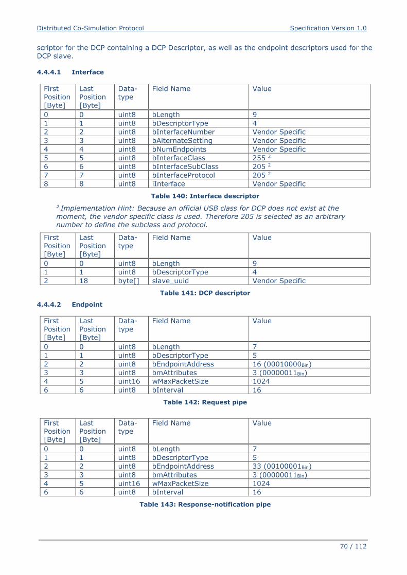
Distributed Co-Simulation Protocol Specification Version 1.0
70 / 112
scriptor for the DCP containing a DCP Descriptor, as well as the endpoint descriptors used for the
DCP slave.
4.4.4.1 Interface
First
Position
[Byte]
Last
Position
[Byte]
Data-
type
Field Name Value
0 0 uint8 bLength 9
1 1 uint8 bDescriptorType 4
2 2 uint8 bInterfaceNumber Vendor Specific
3 3 uint8 bAlternateSetting Vendor Specific
4 4 uint8 bNumEndpoints Vendor Specific
5 5 uint8 bInterfaceClass 255 2
6 6 uint8 bInterfaceSubClass 205 2
7 7 uint8 bInterfaceProtocol 205 2
8 8 uint8 iInterface Vendor Specific
Table 140: Interface descriptor
2 Implementation Hint: Because an official USB class for DCP does not exist at the
moment, the vendor specific class is used. Therefore 205 is selected as an arbitrary
number to define the subclass and protocol.
First
Position
[Byte]
Last
Position
[Byte]
Data-
type
Field Name Value
0 0 uint8 bLength 9
1 1 uint8 bDescriptorType 4
2 18 byte[] slave_uuid Vendor Specific
Table 141: DCP descriptor
4.4.4.2 Endpoint
First
Position
[Byte]
Last
Position
[Byte]
Data-
type
Field Name Value
0 0 uint8 bLength 7
1 1 uint8 bDescriptorType 5
2 2 uint8 bEndpointAddress 16 (00010000Bin)
3 3 uint8 bmAttributes 3 (00000011Bin)
4 5 uint16 wMaxPacketSize 1024
6 6 uint8 bInterval 16
Table 142: Request pipe
First
Position
[Byte]
Last
Position
[Byte]
Data-
type
Field Name Value
0 0 uint8 bLength 7
1 1 uint8 bDescriptorType 5
2 2 uint8 bEndpointAddress 33 (00100001Bin)
3 3 uint8 bmAttributes 3 (00000011Bin)
4 5 uint16 wMaxPacketSize 1024
6 6 uint8 bInterval 16
Table 143: Response-notification pipe
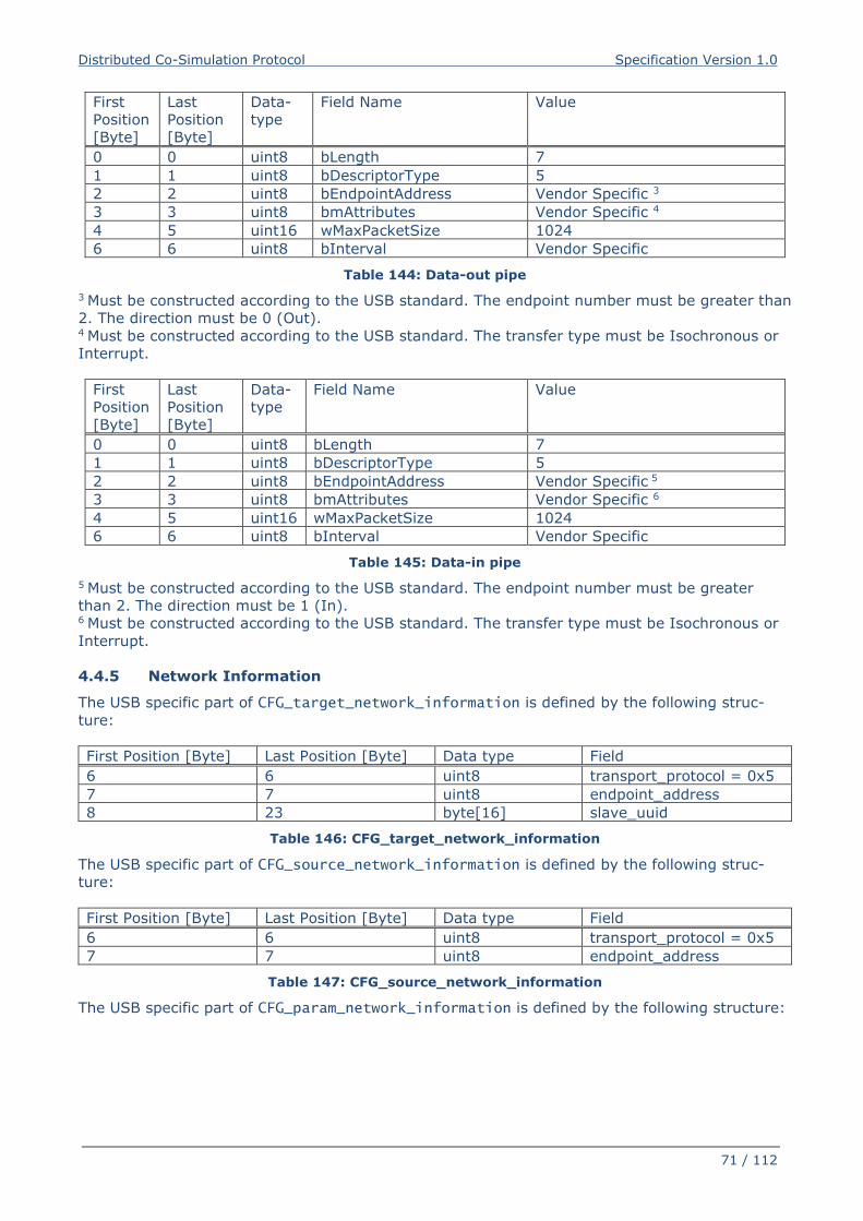
Distributed Co-Simulation Protocol Specification Version 1.0
71 / 112
First
Position
[Byte]
Last
Position
[Byte]
Data-
type
Field Name Value
0 0 uint8 bLength 7
1 1 uint8 bDescriptorType 5
2 2 uint8 bEndpointAddress Vendor Specific 3
3 3 uint8 bmAttributes Vendor Specific 4
4 5 uint16 wMaxPacketSize 1024
6 6 uint8 bInterval Vendor Specific
Table 144: Data-out pipe
3 Must be constructed according to the USB standard. The endpoint number must be greater than
2. The direction must be 0 (Out). 4 Must be constructed according to the USB standard. The transfer type must be Isochronous or
Interrupt.
First
Position
[Byte]
Last
Position
[Byte]
Data-
type
Field Name Value
0 0 uint8 bLength 7
1 1 uint8 bDescriptorType 5
2 2 uint8 bEndpointAddress Vendor Specific 5
3 3 uint8 bmAttributes Vendor Specific 6
4 5 uint16 wMaxPacketSize 1024
6 6 uint8 bInterval Vendor Specific
Table 145: Data-in pipe
5 Must be constructed according to the USB standard. The endpoint number must be greater
than 2. The direction must be 1 (In). 6 Must be constructed according to the USB standard. The transfer type must be Isochronous or
Interrupt.
4.4.5 Network Information
The USB specific part of CFG_target_network_information is defined by the following struc-
ture:
First Position [Byte] Last Position [Byte] Data type Field
6 6 uint8 transport_protocol = 0x5
7 7 uint8 endpoint_address
8 23 byte[16] slave_uuid
Table 146: CFG_target_network_information
The USB specific part of CFG_source_network_information is defined by the following struc-
ture:
First Position [Byte] Last Position [Byte] Data type Field
6 6 uint8 transport_protocol = 0x5
7 7 uint8 endpoint_address
Table 147: CFG_source_network_information
The USB specific part of CFG_param_network_information is defined by the following structure:
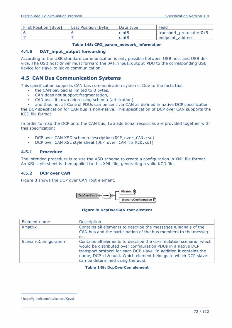
Distributed Co-Simulation Protocol Specification Version 1.0
72 / 112
First Position [Byte] Last Position [Byte] Data type Field
6 6 uint8 transport_protocol = 0x5
7 7 uint8 endpoint_address
Table 148: CFG_param_network_information
4.4.6 DAT_input_output forwarding
According to the USB standard communication is only possible between USB host and USB de-
vice. The USB host driver must forward the DAT_input_output PDU to the corresponding USB
device for slave-to-slave communication.
4.5 CAN Bus Communication Systems
This specification supports CAN bus communication systems. Due to the facts that
• the CAN payload is limited to 8 bytes,
• CAN does not support fragmentation,
• CAN uses its own addressing schema (arbitration)
• and thus not all Control PDUs can be sent via CAN as defined in native DCP specification
the DCP specification for CAN bus is non-native. This specification of DCP over CAN supports the
KCD file format1
In order to map the DCP onto the CAN bus, two additional resources are provided together with
this specification:
• DCP over CAN XSD schema description (DCP_over_CAN.xsd)
• DCP over CAN XSL style sheet (DCP_over_CAN_to_KCD.xsl)
4.5.1 Procedure
The intended procedure is to use the XSD schema to create a configuration in XML file format.
An XSL style sheet is then applied to this XML file, generating a valid KCD file.
4.5.2 DCP over CAN
Figure 8 shows the DCP over CAN root element.
Figure 8: DcpOverCAN root element
Element name Description
KMatrix Contains all elements to describe the messages & signals of the
CAN bus and the participation of the bus members to the messag-
es.
ScenarioConfiguration Contains all elements to describe the co-simulation scenario, which
would be distributed over configuration PDUs in a native DCP
transport protocol for each DCP slave. In addition it contains the
name, DCP id & uuid. Which element belongs to which DCP slave
can be determined using the uuid.
Table 149: DcpOverCan element
1 https://github.com/dschanoeh/Kayak
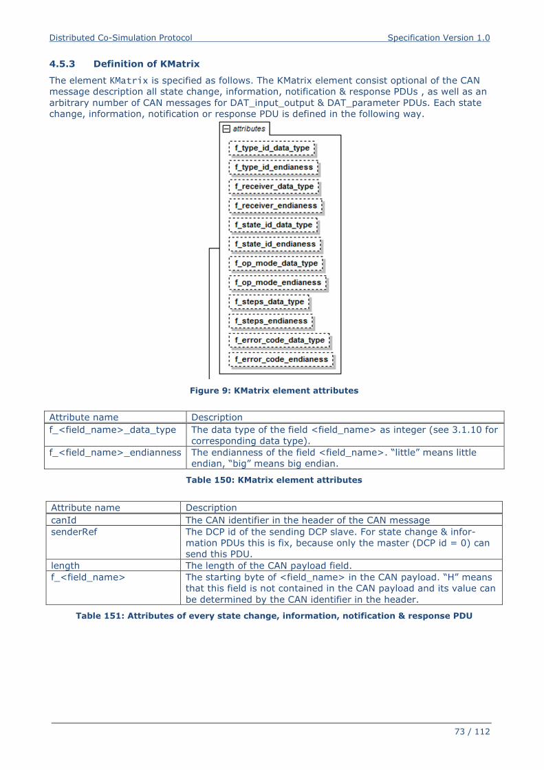
Distributed Co-Simulation Protocol Specification Version 1.0
73 / 112
4.5.3 Definition of KMatrix
The element KMatrix is specified as follows. The KMatrix element consist optional of the CAN
message description all state change, information, notification & response PDUs , as well as an
arbitrary number of CAN messages for DAT_input_output & DAT_parameter PDUs. Each state
change, information, notification or response PDU is defined in the following way.
Figure 9: KMatrix element attributes
Attribute name Description
f_<field_name>_data_type The data type of the field <field_name> as integer (see 3.1.10 for
corresponding data type).
f_<field_name>_endianness The endianness of the field <field_name>. “little” means little
endian, “big” means big endian.
Table 150: KMatrix element attributes
Attribute name Description
canId The CAN identifier in the header of the CAN message
senderRef The DCP id of the sending DCP slave. For state change & infor-
mation PDUs this is fix, because only the master (DCP id = 0) can
send this PDU.
length The length of the CAN payload field.
f_<field_name> The starting byte of <field_name> in the CAN payload. “H” means
that this field is not contained in the CAN payload and its value can
be determined by the CAN identifier in the header.
Table 151: Attributes of every state change, information, notification & response PDU
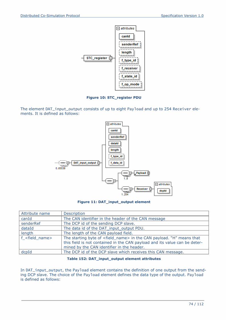
Distributed Co-Simulation Protocol Specification Version 1.0
74 / 112
Figure 10: STC_register PDU
The element DAT_input_output consists of up to eight Payload and up to 254 Receiver ele-
ments. It is defined as follows:
Figure 11: DAT_input_output element
Attribute name Description
canId The CAN identifier in the header of the CAN message
senderRef The DCP id of the sending DCP slave.
dataId The data id of the DAT_input_output PDU.
length The length of the CAN payload field.
f_<field_name> The starting byte of <field_name> in the CAN payload. “H” means that
this field is not contained in the CAN payload and its value can be deter-
mined by the CAN identifier in the header.
dcpId The DCP id of the DCP slave which receives this CAN message.
Table 152: DAT_input_output element attributes
In DAT_input_output, the Payload element contains the definition of one output from the send-
ing DCP slave. The choice of the Payload element defines the data type of the output. Payload
is defined as follows:
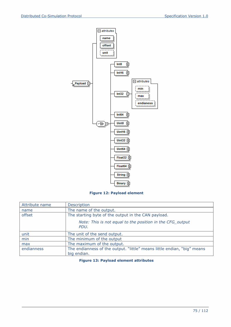
Distributed Co-Simulation Protocol Specification Version 1.0
75 / 112
Figure 12: Payload element
Attribute name Description
name The name of the output.
offset The starting byte of the output in the CAN payload.
Note: This is not equal to the position in the CFG_output
PDU.
unit The unit of the send output.
min The minimum of the output
max The maximum of the output.
endianness The endianness of the output. “little” means little endian, “big” means
big endian.
Figure 13: Payload element attributes
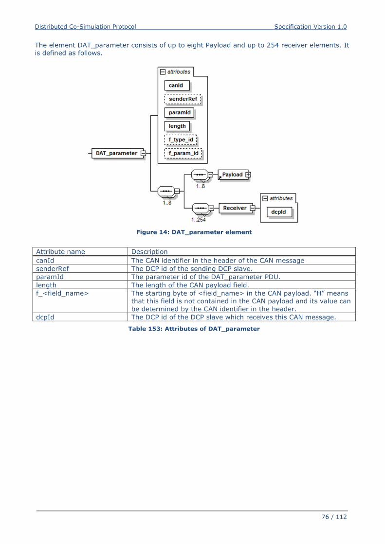
Distributed Co-Simulation Protocol Specification Version 1.0
76 / 112
The element DAT_parameter consists of up to eight Payload and up to 254 receiver elements. It
is defined as follows.
Figure 14: DAT_parameter element
Attribute name Description
canId The CAN identifier in the header of the CAN message
senderRef The DCP id of the sending DCP slave.
paramId The parameter id of the DAT_parameter PDU.
length The length of the CAN payload field.
f_<field_name> The starting byte of <field_name> in the CAN payload. “H” means
that this field is not contained in the CAN payload and its value can
be determined by the CAN identifier in the header.
dcpId The DCP id of the DCP slave which receives this CAN message.
Table 153: Attributes of DAT_parameter
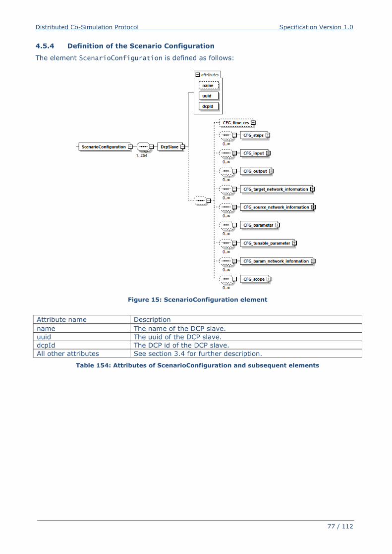
Distributed Co-Simulation Protocol Specification Version 1.0
77 / 112
4.5.4 Definition of the Scenario Configuration
The element ScenarioConfiguration is defined as follows:
Figure 15: ScenarioConfiguration element
Attribute name Description
name The name of the DCP slave.
uuid The uuid of the DCP slave.
dcpId The DCP id of the DCP slave.
All other attributes See section 3.4 for further description.
Table 154: Attributes of ScenarioConfiguration and subsequent elements
Distributed Co-Simulation Protocol Specification Version 1.0
78 / 112
5 DCP Slave Description
5.1 General
All static information related to a DCP slave is stored in an accompanying DCP file. The require-
ments for this file and its internal structure are specified in section 3.1.4. The DCP file must con-
tain at least one DCP slave description file, which is a text file in XML format. It is specified in
detail in this section. The provider of a DCP slave shall ensure that the accompanying DCP file
reflects the implementation of the delivered DCP slave. The DCP slave file shall be consistent
with the delivered DCP slave at all times. The distribution mechanism of the DCP file is arbitrary.
The file extension of a DCP slave description file is “.dcpx”. The structure of this XML file is de-
fined using the schema file dcpSlaveDescription.xsd. This schema file utilizes the following
helper schema files:
dcpAnnotation.xsd dcpAttributeGroups.xsd dcpDataTypes.xsd dcpTransportProtocolTypes.xsd dcpType.xsd dcpUnit.xsd dcpVariable.xsd
These XSD schema files comply with the XSD 1.1 specification [8]. In this section these schema
files are discussed. The normative definition are the above mentioned schema files2. Optional
elements are indicated using a dashed box. The required data types (e.g. xs:normalizedString)
are defined in the XML-schema standard (see http://www.w3.org/TR/xmlschema-2 for more in-
formation).
5.2 Use of Assertions and Constraints
The schema files contain assertions and constraints to support formal verification of properties
and dependencies as stated in this specification document. XSD 1.0 compliant schema files may
be created by transformation using the provided XSLT file (Extensible Stylesheet Language
Transformation):
dcpx_xsd11_to_xsd10.xslt
Note: This XSLT file is provided together with the XSD schema files to ensure correct
transformation. It is intended to remove the assertions.
Note: The defined assertions and constraints were removed from this section’s figures
to facilitate better legibility.
2 The screenshots of this section have been generated from the schema files with the tool “Altova XMLSpy”. Please see
www.altova.com.
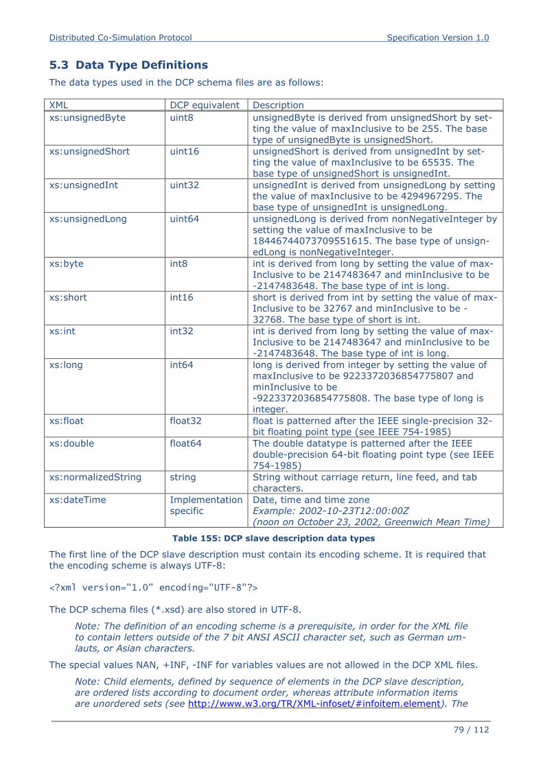
Distributed Co-Simulation Protocol Specification Version 1.0
79 / 112
5.3 Data Type Definitions
The data types used in the DCP schema files are as follows:
XML DCP equivalent Description
xs:unsignedByte uint8 unsignedByte is derived from unsignedShort by set-
ting the value of maxInclusive to be 255. The base
type of unsignedByte is unsignedShort.
xs:unsignedShort uint16 unsignedShort is derived from unsignedInt by set-
ting the value of maxInclusive to be 65535. The
base type of unsignedShort is unsignedInt.
xs:unsignedInt uint32 unsignedInt is derived from unsignedLong by setting
the value of maxInclusive to be 4294967295. The
base type of unsignedInt is unsignedLong.
xs:unsignedLong uint64 unsignedLong is derived from nonNegativeInteger by
setting the value of maxInclusive to be
18446744073709551615. The base type of unsign-
edLong is nonNegativeInteger.
xs:byte int8 int is derived from long by setting the value of max-
Inclusive to be 2147483647 and minInclusive to be
-2147483648. The base type of int is long.
xs:short int16 short is derived from int by setting the value of max-
Inclusive to be 32767 and minInclusive to be -
32768. The base type of short is int.
xs:int int32 int is derived from long by setting the value of max-
Inclusive to be 2147483647 and minInclusive to be
-2147483648. The base type of int is long.
xs:long int64 long is derived from integer by setting the value of
maxInclusive to be 9223372036854775807 and
minInclusive to be
-9223372036854775808. The base type of long is
integer.
xs:float float32 float is patterned after the IEEE single-precision 32-
bit floating point type (see IEEE 754-1985)
xs:double float64 The double datatype is patterned after the IEEE
double-precision 64-bit floating point type (see IEEE
754-1985)
xs:normalizedString string String without carriage return, line feed, and tab
characters.
xs:dateTime Implementation
specific
Date, time and time zone
Example: 2002-10-23T12:00:00Z
(noon on October 23, 2002, Greenwich Mean Time)
Table 155: DCP slave description data types
The first line of the DCP slave description must contain its encoding scheme. It is required that
the encoding scheme is always UTF-8:
<?xml version="1.0" encoding="UTF-8"?>
The DCP schema files (*.xsd) are also stored in UTF-8.
Note: The definition of an encoding scheme is a prerequisite, in order for the XML file
to contain letters outside of the 7 bit ANSI ASCII character set, such as German um-
lauts, or Asian characters.
The special values NAN, +INF, -INF for variables values are not allowed in the DCP XML files.
Note: Child elements, defined by sequence of elements in the DCP slave description,
are ordered lists according to document order, whereas attribute information items
are unordered sets (see http://www.w3.org/TR/XML-infoset/#infoitem.element). The
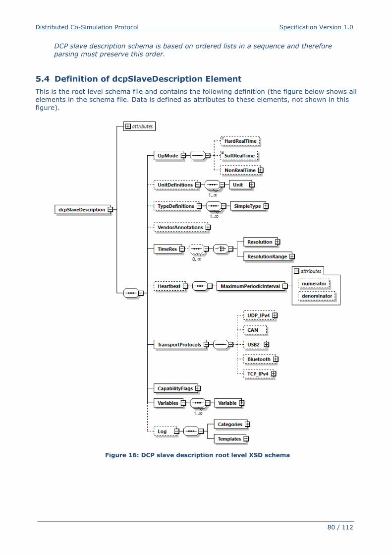
Distributed Co-Simulation Protocol Specification Version 1.0
80 / 112
DCP slave description schema is based on ordered lists in a sequence and therefore
parsing must preserve this order.
5.4 Definition of dcpSlaveDescription Element
This is the root level schema file and contains the following definition (the figure below shows all
elements in the schema file. Data is defined as attributes to these elements, not shown in this
figure).
Figure 16: DCP slave description root level XSD schema
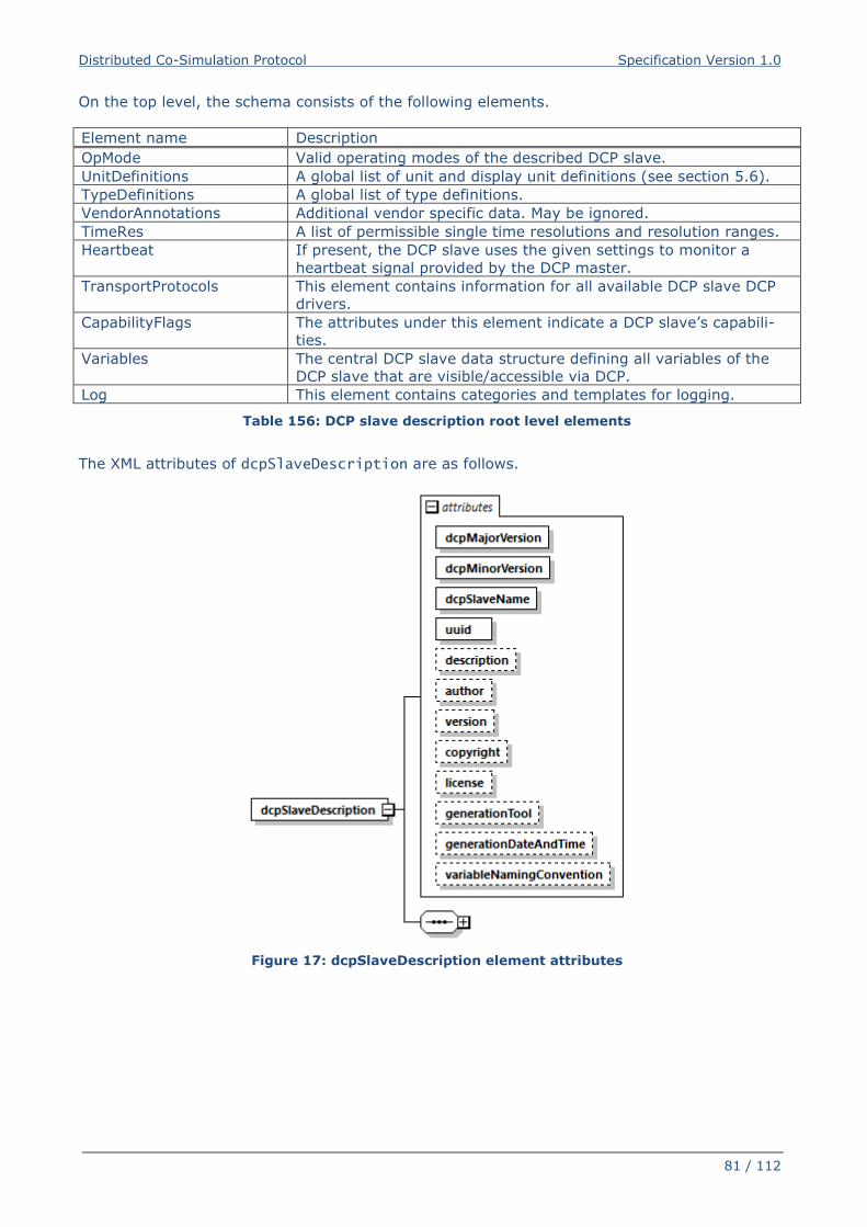
Distributed Co-Simulation Protocol Specification Version 1.0
81 / 112
On the top level, the schema consists of the following elements.
Element name Description
OpMode Valid operating modes of the described DCP slave.
UnitDefinitions A global list of unit and display unit definitions (see section 5.6).
TypeDefinitions A global list of type definitions.
VendorAnnotations Additional vendor specific data. May be ignored.
TimeRes A list of permissible single time resolutions and resolution ranges.
Heartbeat If present, the DCP slave uses the given settings to monitor a
heartbeat signal provided by the DCP master.
TransportProtocols This element contains information for all available DCP slave DCP
drivers.
CapabilityFlags The attributes under this element indicate a DCP slave’s capabili-
ties.
Variables The central DCP slave data structure defining all variables of the
DCP slave that are visible/accessible via DCP.
Log This element contains categories and templates for logging.
Table 156: DCP slave description root level elements
The XML attributes of dcpSlaveDescription are as follows.
Figure 17: dcpSlaveDescription element attributes
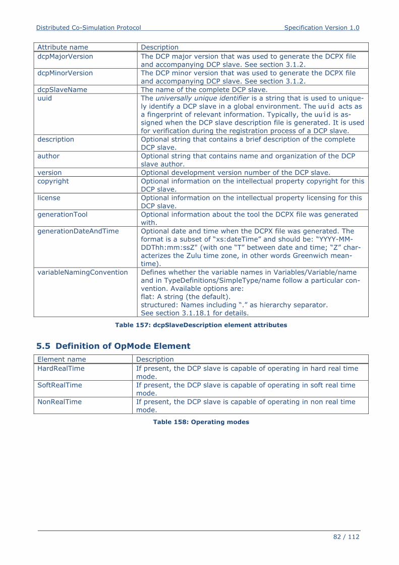
Distributed Co-Simulation Protocol Specification Version 1.0
82 / 112
Attribute name Description
dcpMajorVersion The DCP major version that was used to generate the DCPX file
and accompanying DCP slave. See section 3.1.2.
dcpMinorVersion The DCP minor version that was used to generate the DCPX file
and accompanying DCP slave. See section 3.1.2.
dcpSlaveName The name of the complete DCP slave.
uuid The universally unique identifier is a string that is used to unique-
ly identify a DCP slave in a global environment. The uuid acts as
a fingerprint of relevant information. Typically, the uuid is as-
signed when the DCP slave description file is generated. It is used
for verification during the registration process of a DCP slave.
description Optional string that contains a brief description of the complete
DCP slave.
author Optional string that contains name and organization of the DCP
slave author.
version Optional development version number of the DCP slave.
copyright Optional information on the intellectual property copyright for this
DCP slave.
license Optional information on the intellectual property licensing for this
DCP slave.
generationTool Optional information about the tool the DCPX file was generated
with.
generationDateAndTime Optional date and time when the DCPX file was generated. The
format is a subset of “xs:dateTime” and should be: “YYYY-MM-
DDThh:mm:ssZ" (with one “T” between date and time; “Z” char-
acterizes the Zulu time zone, in other words Greenwich mean-
time).
variableNamingConvention Defines whether the variable names in Variables/Variable/name
and in TypeDefinitions/SimpleType/name follow a particular con-
vention. Available options are:
flat: A string (the default).
structured: Names including “.” as hierarchy separator.
See section 3.1.18.1 for details.
Table 157: dcpSlaveDescription element attributes
5.5 Definition of OpMode Element
Element name Description
HardRealTime If present, the DCP slave is capable of operating in hard real time
mode.
SoftRealTime If present, the DCP slave is capable of operating in soft real time
mode.
NonRealTime If present, the DCP slave is capable of operating in non real time
mode.
Table 158: Operating modes
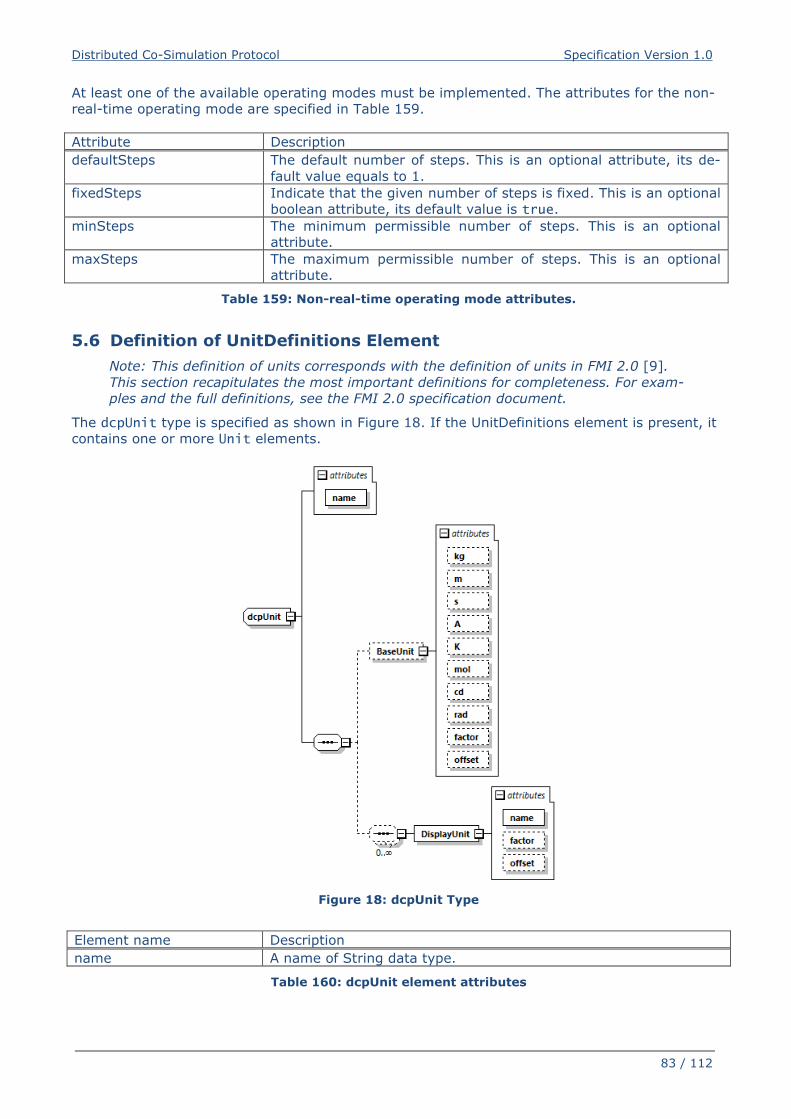
Distributed Co-Simulation Protocol Specification Version 1.0
83 / 112
At least one of the available operating modes must be implemented. The attributes for the non-
real-time operating mode are specified in Table 159.
Attribute Description
defaultSteps The default number of steps. This is an optional attribute, its de-
fault value equals to 1.
fixedSteps Indicate that the given number of steps is fixed. This is an optional
boolean attribute, its default value is true.
minSteps The minimum permissible number of steps. This is an optional
attribute.
maxSteps The maximum permissible number of steps. This is an optional
attribute.
Table 159: Non-real-time operating mode attributes.
5.6 Definition of UnitDefinitions Element
Note: This definition of units corresponds with the definition of units in FMI 2.0 [9].
This section recapitulates the most important definitions for completeness. For exam-
ples and the full definitions, see the FMI 2.0 specification document.
The dcpUnit type is specified as shown in Figure 18. If the UnitDefinitions element is present, it
contains one or more Unit elements.
Figure 18: dcpUnit Type
Element name Description
name A name of String data type.
Table 160: dcpUnit element attributes
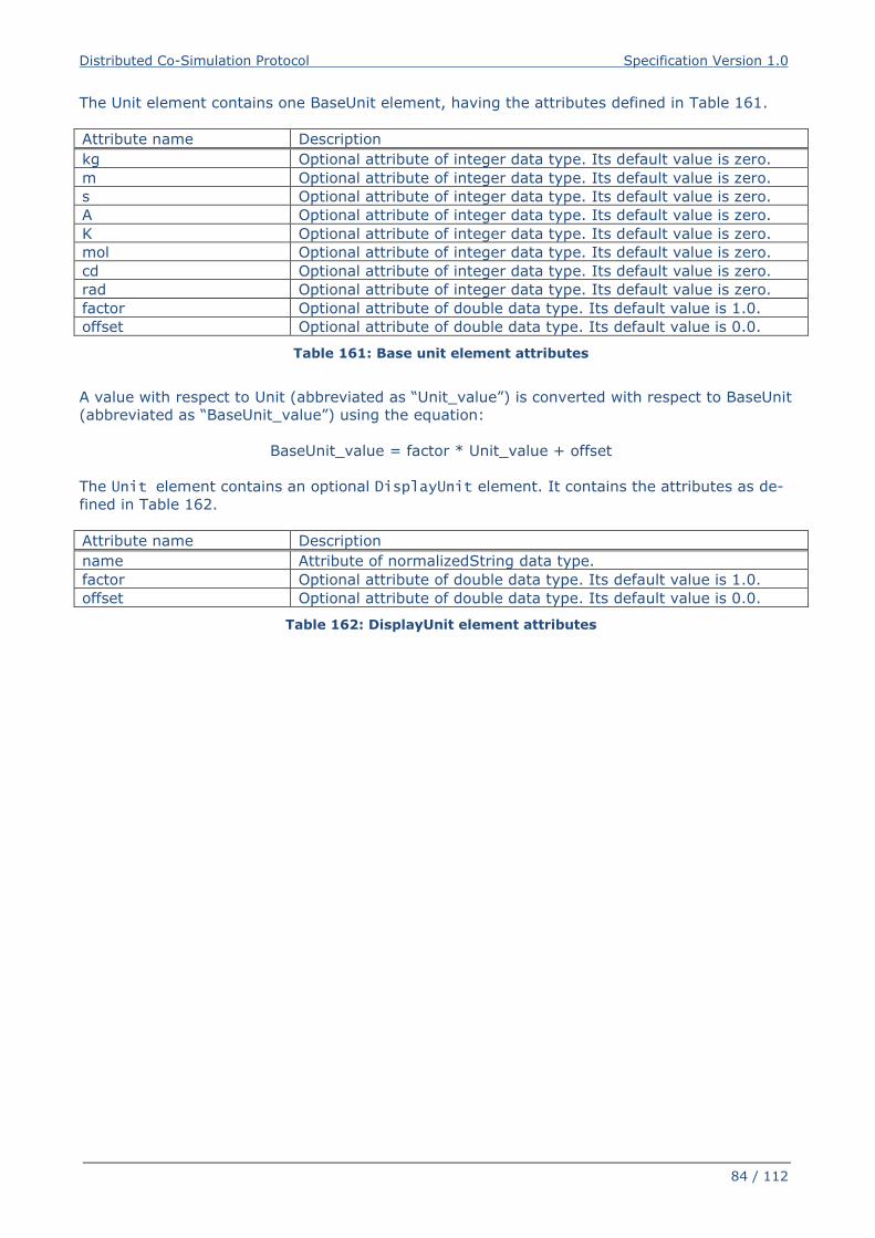
Distributed Co-Simulation Protocol Specification Version 1.0
84 / 112
The Unit element contains one BaseUnit element, having the attributes defined in Table 161.
Attribute name Description
kg Optional attribute of integer data type. Its default value is zero.
m Optional attribute of integer data type. Its default value is zero.
s Optional attribute of integer data type. Its default value is zero.
A Optional attribute of integer data type. Its default value is zero.
K Optional attribute of integer data type. Its default value is zero.
mol Optional attribute of integer data type. Its default value is zero.
cd Optional attribute of integer data type. Its default value is zero.
rad Optional attribute of integer data type. Its default value is zero.
factor Optional attribute of double data type. Its default value is 1.0.
offset Optional attribute of double data type. Its default value is 0.0.
Table 161: Base unit element attributes
A value with respect to Unit (abbreviated as “Unit_value”) is converted with respect to BaseUnit
(abbreviated as “BaseUnit_value”) using the equation:
BaseUnit_value = factor * Unit_value + offset
The Unit element contains an optional DisplayUnit element. It contains the attributes as de-
fined in Table 162.
Attribute name Description
name Attribute of normalizedString data type.
factor Optional attribute of double data type. Its default value is 1.0.
offset Optional attribute of double data type. Its default value is 0.0.
Table 162: DisplayUnit element attributes
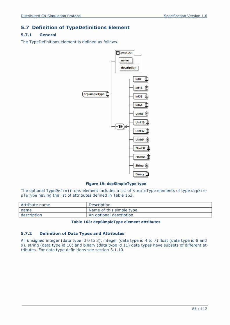
Distributed Co-Simulation Protocol Specification Version 1.0
85 / 112
5.7 Definition of TypeDefinitions Element
5.7.1 General
The TypeDefinitions element is defined as follows.
Figure 19: dcpSimpleType type
The optional TypeDefinitions element includes a list of SimpleType elements of type dcpSim-pleType having the list of attributes defined in Table 163.
Attribute name Description
name Name of this simple type.
description An optional description.
Table 163: dcpSimpleType element attributes
5.7.2 Definition of Data Types and Attributes
All unsigned integer (data type id 0 to 3), integer (data type id 4 to 7) float (data type id 8 and
9), string (data type id 10) and binary (data type id 11) data types have subsets of different at-
tributes. For data type definitions see section 3.1.10.
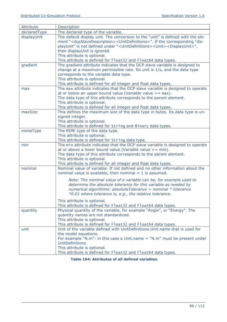
Distributed Co-Simulation Protocol Specification Version 1.0
86 / 112
Attribute Description
declaredType The declared type of the variable.
displayUnit The default display unit. The conversion to the “unit” is defined with the ele-
ment “<dcpSlaveDescription><UnitDefinitions>”. If the corresponding “dis-
playUnit” is not defined under “<UnitDefinitions><Unit><DisplayUnit>”,
then displayUnit is ignored.
This attribute is optional.
This attribute is defined for Float32 and Float64 data types.
gradient The gradient attribute indicates that the DCP slave variable is designed to
change at a maximum permissible rate. Its unit is 1/s, and the data type
corresponds to the variable data type.
This attribute is optional.
This attribute is defined for all integer and float data types.
max The max attribute indicates that the DCP slave variable is designed to operate
at or below an upper bound value (Variable value >= max).
The data type of this attribute corresponds to the parent element.
This attribute is optional.
This attribute is defined for all integer and float data types.
maxSize This defines the maximum size of the data type in bytes. Its data type is un-
signed integer.
This attribute is optional.
This attribute is defined for String and Binary data types.
mimeType The MIME type of the data type.
This attribute is optional.
This attribute is defined for String data type.
min The min attribute indicates that the DCP slave variable is designed to operate
at or above a lower bound value (Variable value >= min).
The data type of this attribute corresponds to the parent element.
This attribute is optional.
This attribute is defined for all integer and float data types.
nominal Nominal value of variable. If not defined and no other information about the
nominal value is available, then nominal = 1 is assumed.
Note: The nominal value of a variable can be, for example used to
determine the absolute tolerance for this variable as needed by
numerical algorithms: absoluteTolerance = nominal * tolerance
*0.01 where tolerance is, e.g., the relative tolerance.
This attribute is optional.
This attribute is defined for Float32 and Float64 data types.
quantity Physical quantity of the variable, for example “Angle”, or “Energy”. The
quantity names are not standardized.
This attribute is optional.
This attribute is defined for Float32 and Float64 data types.
unit Unit of the variable defined with UnitDefinitions.Unit.name that is used for
the model equations.
For example “N.m”: in this case a Unit.name = "N.m" must be present under
UnitDefinitions.
This attribute is optional.
This attribute is defined for Float32 and Float64 data types.
Table 164: Attributes of all defined variables.
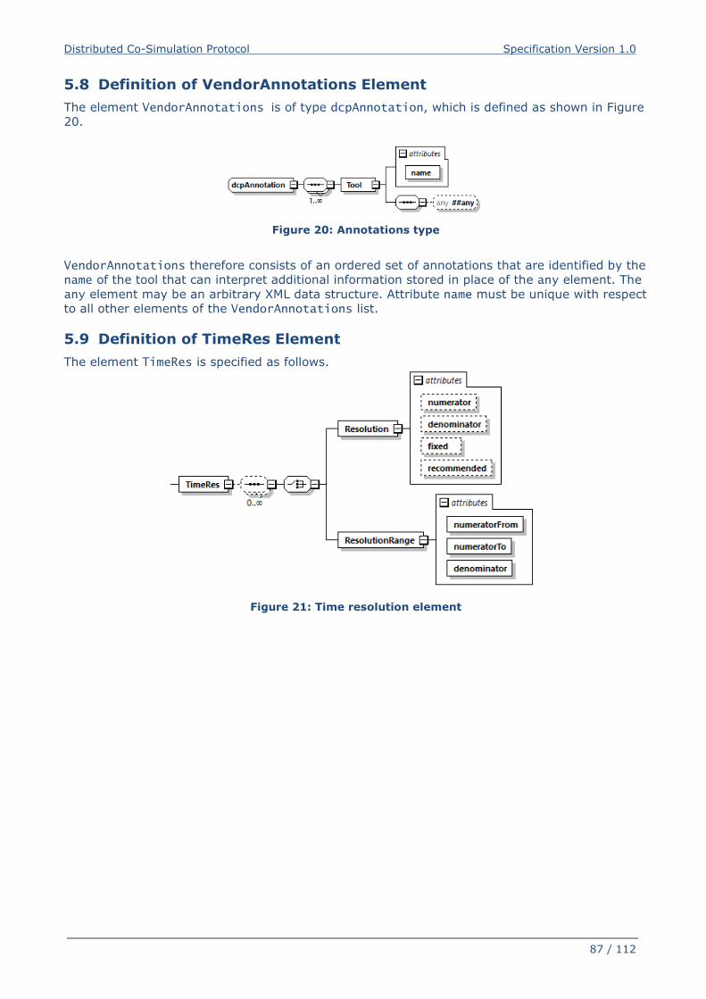
Distributed Co-Simulation Protocol Specification Version 1.0
87 / 112
5.8 Definition of VendorAnnotations Element
The element VendorAnnotations is of type dcpAnnotation, which is defined as shown in Figure
20.
Figure 20: Annotations type
VendorAnnotations therefore consists of an ordered set of annotations that are identified by the
name of the tool that can interpret additional information stored in place of the any element. The
any element may be an arbitrary XML data structure. Attribute name must be unique with respect
to all other elements of the VendorAnnotations list.
5.9 Definition of TimeRes Element
The element TimeRes is specified as follows.
Figure 21: Time resolution element
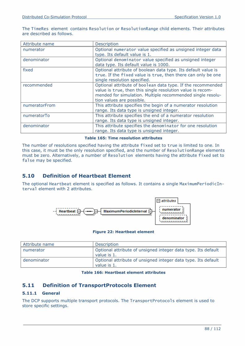
Distributed Co-Simulation Protocol Specification Version 1.0
88 / 112
The TimeRes element contains Resolution or ResolutionRange child elements. Their attributes
are described as follows.
Attribute name Description
numerator Optional numerator value specified as unsigned integer data
type. Its default value is 1.
denominator Optional denominator value specified as unsigned integer
data type. Its default value is 1000.
fixed Optional attribute of boolean data type. Its default value is
true. If the fixed value is true, then there can only be one
single resolution specified.
recommended Optional attribute of boolean data type. If the recommended
value is true, then this single resolution value is recom-
mended for simulation. Multiple recommended single resolu-
tion values are possible.
numeratorFrom This attribute specifies the begin of a numerator resolution
range. Its data type is unsigned integer.
numeratorTo This attribute specifies the end of a numerator resolution
range. Its data type is unsigned integer.
denominator This attribute specifies the denominator for one resolution
range. Its data type is unsigned integer.
Table 165: Time resolution attributes
The number of resolutions specified having the attribute fixed set to true is limited to one. In
this case, it must be the only resolution specified, and the number of ResolutionRange elements
must be zero. Alternatively, a number of Resolution elements having the attribute fixed set to
false may be specified.
5.10 Definition of Heartbeat Element
The optional Heartbeat element is specified as follows. It contains a single MaximumPeriodicIn-terval element with 2 attributes.
Figure 22: Heartbeat element
Attribute name Description
numerator Optional attribute of unsigned integer data type. Its default
value is 1.
denominator Optional attribute of unsigned integer data type. Its default
value is 1.
Table 166: Heartbeat element attributes
5.11 Definition of TransportProtocols Element
5.11.1 General
The DCP supports multiple transport protocols. The TransportProtocols element is used to
store specific settings.
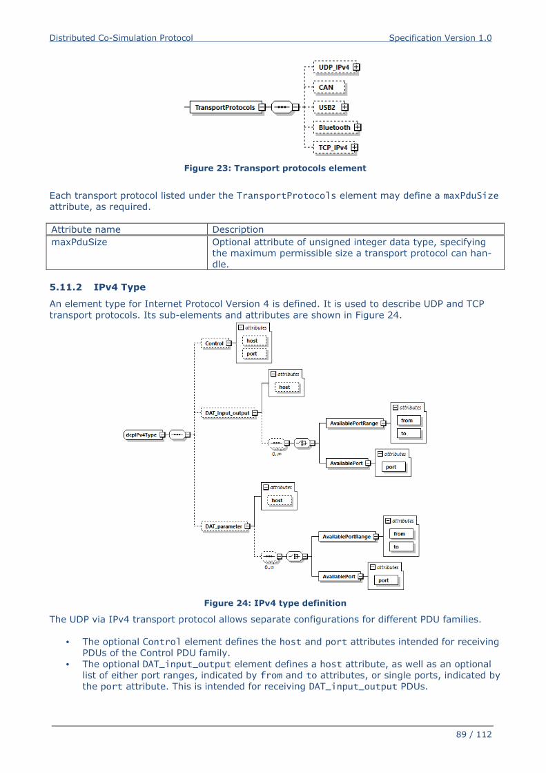
Distributed Co-Simulation Protocol Specification Version 1.0
89 / 112
Figure 23: Transport protocols element
Each transport protocol listed under the TransportProtocols element may define a maxPduSize
attribute, as required.
Attribute name Description
maxPduSize Optional attribute of unsigned integer data type, specifying
the maximum permissible size a transport protocol can han-
dle.
5.11.2 IPv4 Type
An element type for Internet Protocol Version 4 is defined. It is used to describe UDP and TCP
transport protocols. Its sub-elements and attributes are shown in Figure 24.
Figure 24: IPv4 type definition
The UDP via IPv4 transport protocol allows separate configurations for different PDU families.
• The optional Control element defines the host and port attributes intended for receiving
PDUs of the Control PDU family.
• The optional DAT_input_output element defines a host attribute, as well as an optional
list of either port ranges, indicated by from and to attributes, or single ports, indicated by
the port attribute. This is intended for receiving DAT_input_output PDUs.
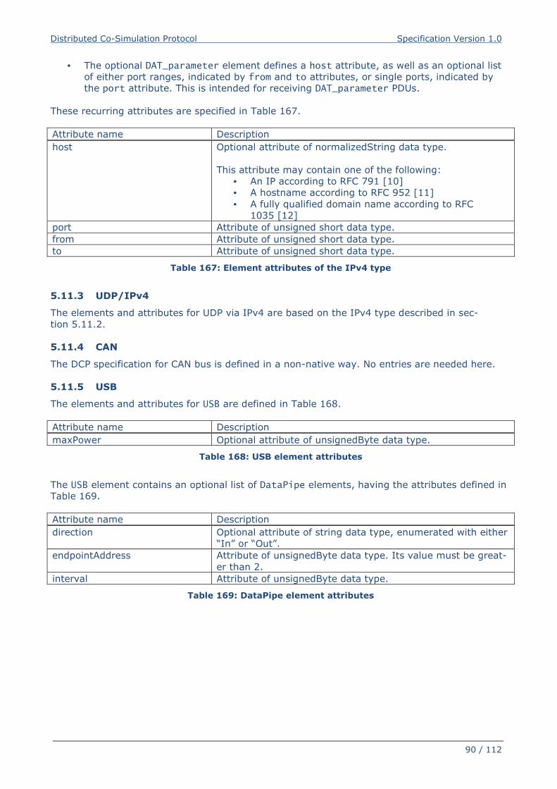
Distributed Co-Simulation Protocol Specification Version 1.0
90 / 112
• The optional DAT_parameter element defines a host attribute, as well as an optional list
of either port ranges, indicated by from and to attributes, or single ports, indicated by
the port attribute. This is intended for receiving DAT_parameter PDUs.
These recurring attributes are specified in Table 167.
Attribute name Description
host Optional attribute of normalizedString data type.
This attribute may contain one of the following:
• An IP according to RFC 791 [10]
• A hostname according to RFC 952 [11]
• A fully qualified domain name according to RFC
1035 [12]
port Attribute of unsigned short data type.
from Attribute of unsigned short data type.
to Attribute of unsigned short data type.
Table 167: Element attributes of the IPv4 type
5.11.3 UDP/IPv4
The elements and attributes for UDP via IPv4 are based on the IPv4 type described in sec-
tion 5.11.2.
5.11.4 CAN
The DCP specification for CAN bus is defined in a non-native way. No entries are needed here.
5.11.5 USB
The elements and attributes for USB are defined in Table 168.
Attribute name Description
maxPower Optional attribute of unsignedByte data type.
Table 168: USB element attributes
The USB element contains an optional list of DataPipe elements, having the attributes defined in
Table 169.
Attribute name Description
direction Optional attribute of string data type, enumerated with either
“In” or “Out”.
endpointAddress Attribute of unsignedByte data type. Its value must be great-
er than 2.
interval Attribute of unsignedByte data type.
Table 169: DataPipe element attributes
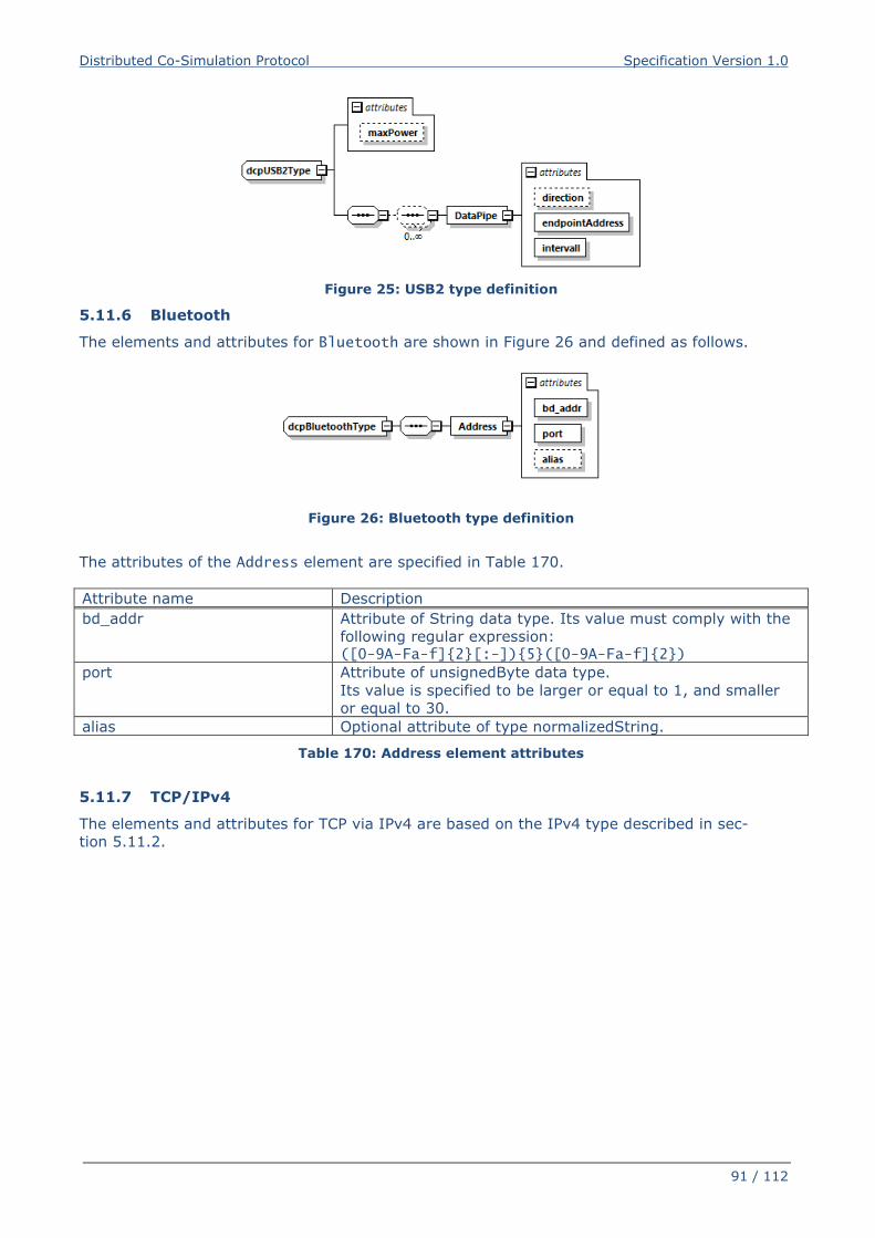
Distributed Co-Simulation Protocol Specification Version 1.0
91 / 112
Figure 25: USB2 type definition
5.11.6 Bluetooth
The elements and attributes for Bluetooth are shown in Figure 26 and defined as follows.
Figure 26: Bluetooth type definition
The attributes of the Address element are specified in Table 170.
Attribute name Description
bd_addr Attribute of String data type. Its value must comply with the
following regular expression: ([0-9A-Fa-f]{2}[:-]){5}([0-9A-Fa-f]{2})
port Attribute of unsignedByte data type.
Its value is specified to be larger or equal to 1, and smaller
or equal to 30.
alias Optional attribute of type normalizedString.
Table 170: Address element attributes
5.11.7 TCP/IPv4
The elements and attributes for TCP via IPv4 are based on the IPv4 type described in sec-
tion 5.11.2.
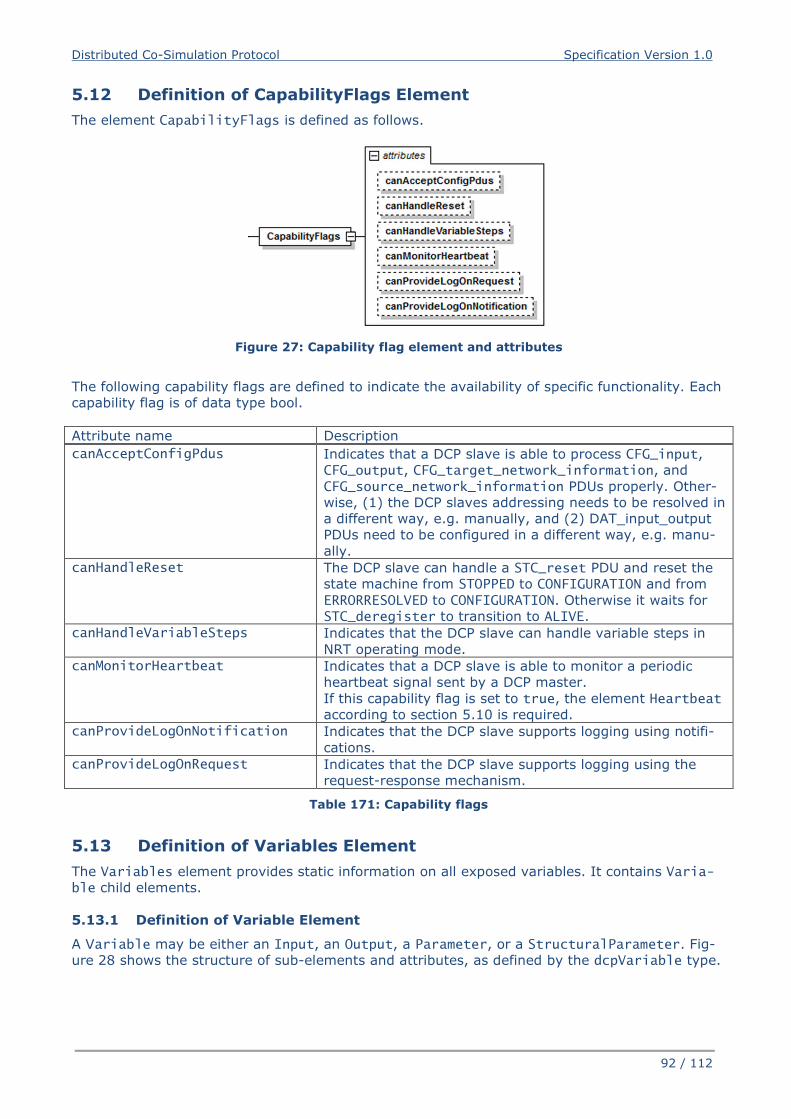
Distributed Co-Simulation Protocol Specification Version 1.0
92 / 112
5.12 Definition of CapabilityFlags Element
The element CapabilityFlags is defined as follows.
Figure 27: Capability flag element and attributes
The following capability flags are defined to indicate the availability of specific functionality. Each
capability flag is of data type bool.
Attribute name Description
canAcceptConfigPdus Indicates that a DCP slave is able to process CFG_input,
CFG_output, CFG_target_network_information, and
CFG_source_network_information PDUs properly. Other-
wise, (1) the DCP slaves addressing needs to be resolved in
a different way, e.g. manually, and (2) DAT_input_output
PDUs need to be configured in a different way, e.g. manu-
ally.
canHandleReset The DCP slave can handle a STC_reset PDU and reset the
state machine from STOPPED to CONFIGURATION and from ERRORRESOLVED to CONFIGURATION. Otherwise it waits for
STC_deregister to transition to ALIVE.
canHandleVariableSteps Indicates that the DCP slave can handle variable steps in
NRT operating mode.
canMonitorHeartbeat Indicates that a DCP slave is able to monitor a periodic
heartbeat signal sent by a DCP master.
If this capability flag is set to true, the element Heartbeat
according to section 5.10 is required.
canProvideLogOnNotification Indicates that the DCP slave supports logging using notifi-
cations.
canProvideLogOnRequest Indicates that the DCP slave supports logging using the
request-response mechanism.
Table 171: Capability flags
5.13 Definition of Variables Element
The Variables element provides static information on all exposed variables. It contains Varia-ble child elements.
5.13.1 Definition of Variable Element
A Variable may be either an Input, an Output, a Parameter, or a StructuralParameter. Fig-
ure 28 shows the structure of sub-elements and attributes, as defined by the dcpVariable type.
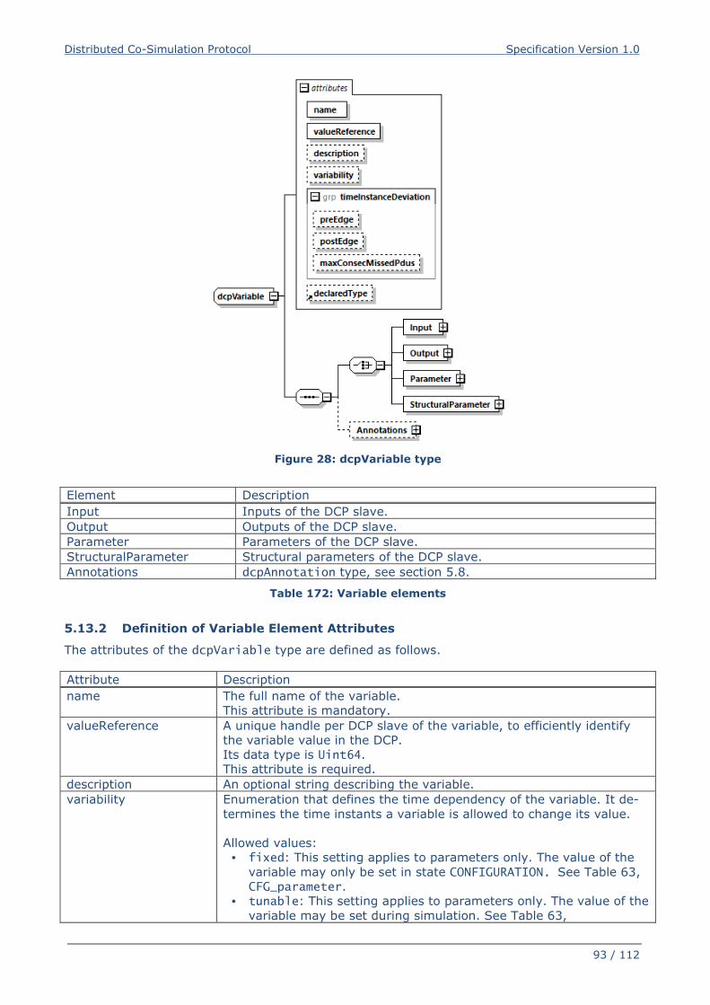
Distributed Co-Simulation Protocol Specification Version 1.0
93 / 112
Figure 28: dcpVariable type
Element Description
Input Inputs of the DCP slave.
Output Outputs of the DCP slave.
Parameter Parameters of the DCP slave.
StructuralParameter Structural parameters of the DCP slave.
Annotations dcpAnnotation type, see section 5.8.
Table 172: Variable elements
5.13.2 Definition of Variable Element Attributes
The attributes of the dcpVariable type are defined as follows.
Attribute Description
name The full name of the variable.
This attribute is mandatory.
valueReference A unique handle per DCP slave of the variable, to efficiently identify
the variable value in the DCP.
Its data type is Uint64.
This attribute is required.
description An optional string describing the variable.
variability Enumeration that defines the time dependency of the variable. It de-
termines the time instants a variable is allowed to change its value.
Allowed values:
• fixed: This setting applies to parameters only. The value of the
variable may only be set in state CONFIGURATION. See Table 63,
CFG_parameter.
• tunable: This setting applies to parameters only. The value of the
variable may be set during simulation. See Table 63,
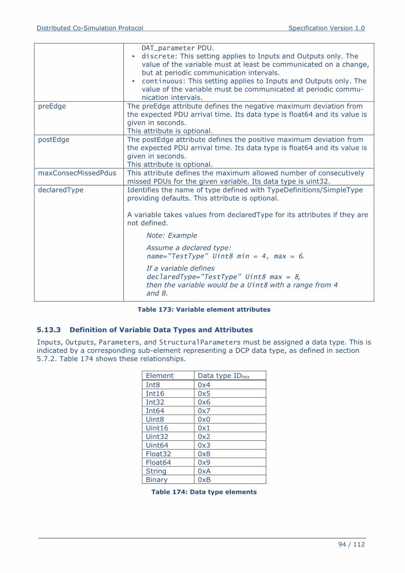
Distributed Co-Simulation Protocol Specification Version 1.0
94 / 112
DAT_parameter PDU.
• discrete: This setting applies to Inputs and Outputs only. The
value of the variable must at least be communicated on a change,
but at periodic communication intervals.
• continuous: This setting applies to Inputs and Outputs only. The
value of the variable must be communicated at periodic commu-
nication intervals.
preEdge The preEdge attribute defines the negative maximum deviation from
the expected PDU arrival time. Its data type is float64 and its value is
given in seconds.
This attribute is optional.
postEdge The postEdge attribute defines the positive maximum deviation from
the expected PDU arrival time. Its data type is float64 and its value is
given in seconds.
This attribute is optional.
maxConsecMissedPdus This attribute defines the maximum allowed number of consecutively
missed PDUs for the given variable. Its data type is uint32.
declaredType Identifies the name of type defined with TypeDefinitions/SimpleType
providing defaults. This attribute is optional.
A variable takes values from declaredType for its attributes if they are
not defined.
Note: Example
Assume a declared type:
name="TestType" Uint8 min = 4, max = 6.
If a variable defines
declaredType="TestType" Uint8 max = 8,
then the variable would be a Uint8 with a range from 4
and 8.
Table 173: Variable element attributes
5.13.3 Definition of Variable Data Types and Attributes
Inputs, Outputs, Parameters, and StructuralParameters must be assigned a data type. This is
indicated by a corresponding sub-element representing a DCP data type, as defined in section
5.7.2. Table 174 shows these relationships.
Element Data type IDhex
Int8 0x4
Int16 0x5
Int32 0x6
Int64 0x7
Uint8 0x0
Uint16 0x1
Uint32 0x2
Uint64 0x3
Float32 0x8
Float64 0x9
String 0xA
Binary 0xB
Table 174: Data type elements
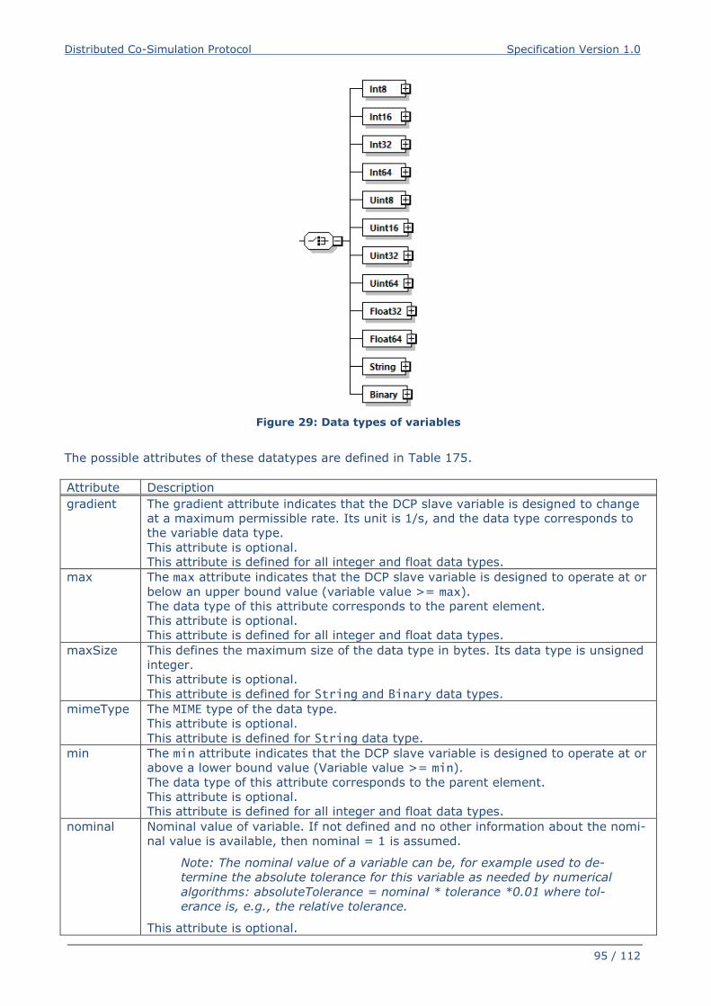
Distributed Co-Simulation Protocol Specification Version 1.0
95 / 112
Figure 29: Data types of variables
The possible attributes of these datatypes are defined in Table 175.
Attribute Description
gradient The gradient attribute indicates that the DCP slave variable is designed to change
at a maximum permissible rate. Its unit is 1/s, and the data type corresponds to
the variable data type.
This attribute is optional.
This attribute is defined for all integer and float data types.
max The max attribute indicates that the DCP slave variable is designed to operate at or
below an upper bound value (variable value >= max).
The data type of this attribute corresponds to the parent element.
This attribute is optional.
This attribute is defined for all integer and float data types.
maxSize This defines the maximum size of the data type in bytes. Its data type is unsigned
integer.
This attribute is optional.
This attribute is defined for String and Binary data types.
mimeType The MIME type of the data type.
This attribute is optional.
This attribute is defined for String data type.
min The min attribute indicates that the DCP slave variable is designed to operate at or
above a lower bound value (Variable value >= min).
The data type of this attribute corresponds to the parent element.
This attribute is optional.
This attribute is defined for all integer and float data types.
nominal Nominal value of variable. If not defined and no other information about the nomi-
nal value is available, then nominal = 1 is assumed.
Note: The nominal value of a variable can be, for example used to de-
termine the absolute tolerance for this variable as needed by numerical
algorithms: absoluteTolerance = nominal * tolerance *0.01 where tol-
erance is, e.g., the relative tolerance.
This attribute is optional.
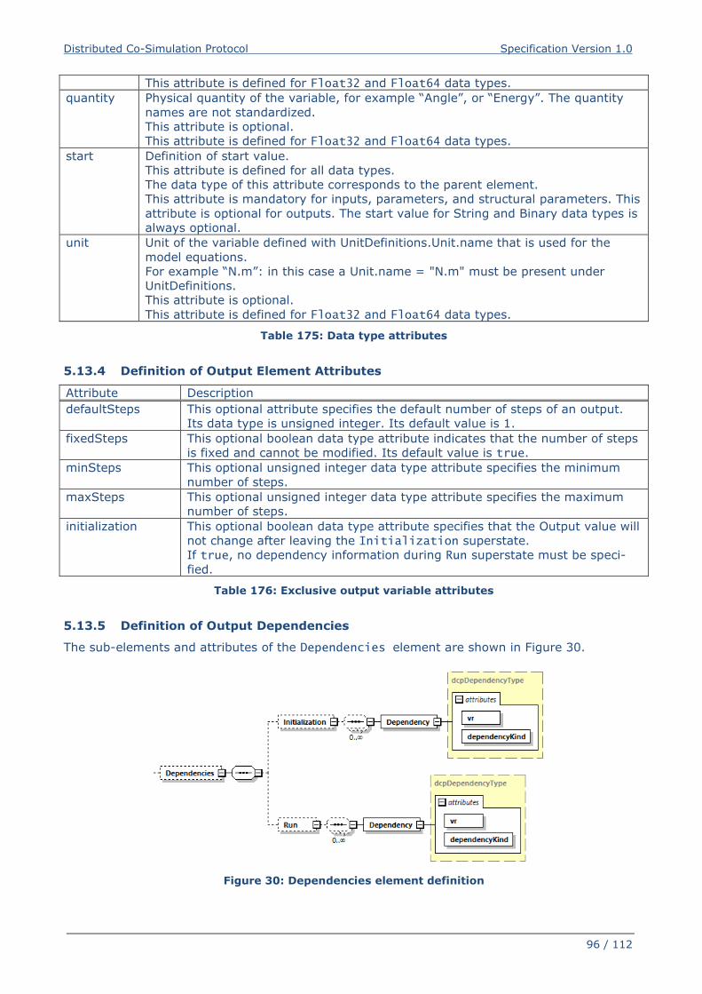
Distributed Co-Simulation Protocol Specification Version 1.0
96 / 112
This attribute is defined for Float32 and Float64 data types.
quantity Physical quantity of the variable, for example “Angle”, or “Energy”. The quantity
names are not standardized.
This attribute is optional.
This attribute is defined for Float32 and Float64 data types.
start Definition of start value.
This attribute is defined for all data types.
The data type of this attribute corresponds to the parent element.
This attribute is mandatory for inputs, parameters, and structural parameters. This
attribute is optional for outputs. The start value for String and Binary data types is
always optional.
unit Unit of the variable defined with UnitDefinitions.Unit.name that is used for the
model equations.
For example “N.m”: in this case a Unit.name = "N.m" must be present under
UnitDefinitions.
This attribute is optional.
This attribute is defined for Float32 and Float64 data types.
Table 175: Data type attributes
5.13.4 Definition of Output Element Attributes
Attribute Description
defaultSteps This optional attribute specifies the default number of steps of an output.
Its data type is unsigned integer. Its default value is 1.
fixedSteps This optional boolean data type attribute indicates that the number of steps
is fixed and cannot be modified. Its default value is true.
minSteps This optional unsigned integer data type attribute specifies the minimum
number of steps.
maxSteps This optional unsigned integer data type attribute specifies the maximum
number of steps.
initialization This optional boolean data type attribute specifies that the Output value will
not change after leaving the Initialization superstate.
If true, no dependency information during Run superstate must be speci-
fied.
Table 176: Exclusive output variable attributes
5.13.5 Definition of Output Dependencies
The sub-elements and attributes of the Dependencies element are shown in Figure 30.
Figure 30: Dependencies element definition
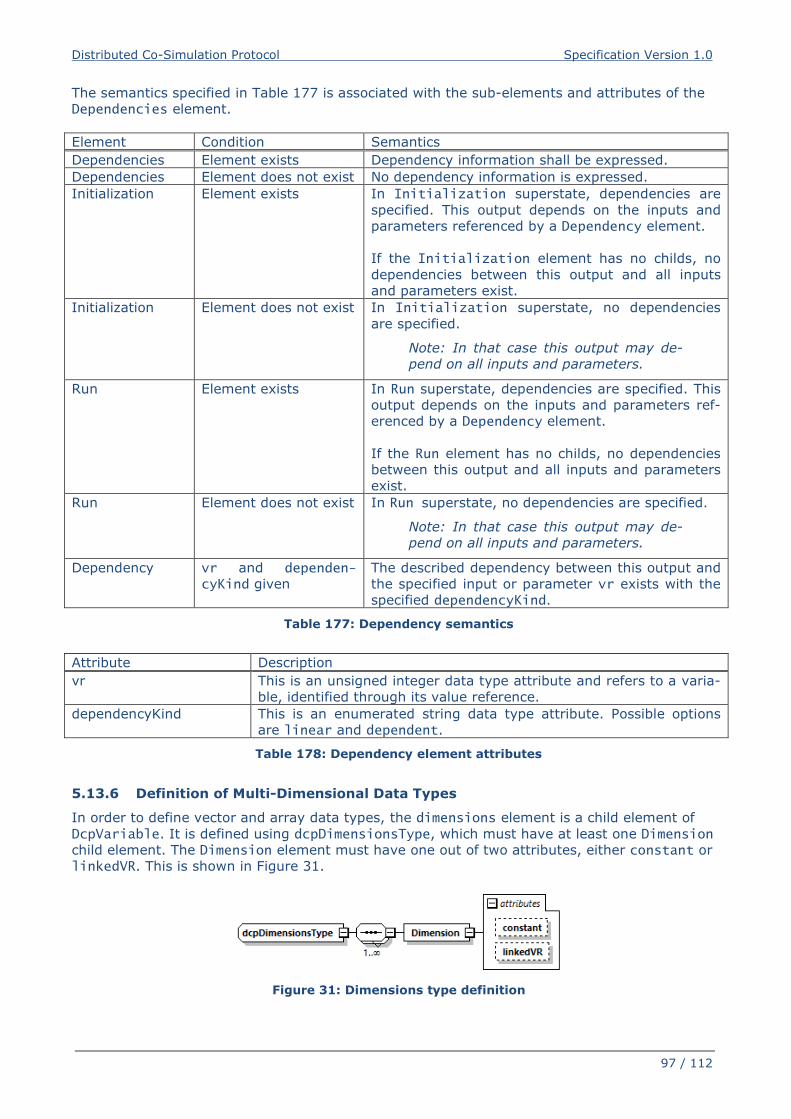
Distributed Co-Simulation Protocol Specification Version 1.0
97 / 112
The semantics specified in Table 177 is associated with the sub-elements and attributes of the
Dependencies element.
Element Condition Semantics
Dependencies Element exists Dependency information shall be expressed.
Dependencies Element does not exist No dependency information is expressed.
Initialization Element exists In Initialization superstate, dependencies are
specified. This output depends on the inputs and
parameters referenced by a Dependency element.
If the Initialization element has no childs, no
dependencies between this output and all inputs
and parameters exist.
Initialization Element does not exist In Initialization superstate, no dependencies
are specified.
Note: In that case this output may de-
pend on all inputs and parameters.
Run Element exists In Run superstate, dependencies are specified. This
output depends on the inputs and parameters ref-
erenced by a Dependency element.
If the Run element has no childs, no dependencies
between this output and all inputs and parameters
exist.
Run Element does not exist In Run superstate, no dependencies are specified.
Note: In that case this output may de-
pend on all inputs and parameters.
Dependency vr and dependen-cyKind given
The described dependency between this output and
the specified input or parameter vr exists with the
specified dependencyKind.
Table 177: Dependency semantics
Attribute Description
vr This is an unsigned integer data type attribute and refers to a varia-
ble, identified through its value reference.
dependencyKind This is an enumerated string data type attribute. Possible options
are linear and dependent.
Table 178: Dependency element attributes
5.13.6 Definition of Multi-Dimensional Data Types
In order to define vector and array data types, the dimensions element is a child element of
DcpVariable. It is defined using dcpDimensionsType, which must have at least one Dimension
child element. The Dimension element must have one out of two attributes, either constant or
linkedVR. This is shown in Figure 31.
Figure 31: Dimensions type definition
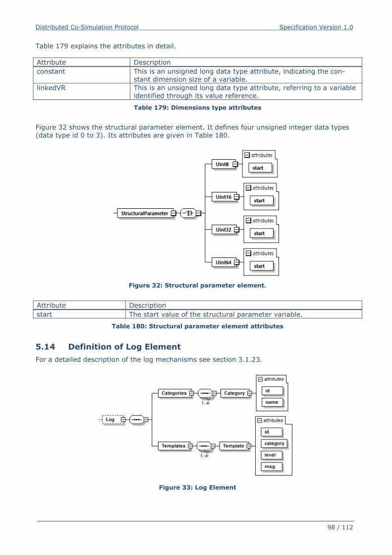
Distributed Co-Simulation Protocol Specification Version 1.0
98 / 112
Table 179 explains the attributes in detail.
Attribute Description
constant This is an unsigned long data type attribute, indicating the con-
stant dimension size of a variable.
linkedVR This is an unsigned long data type attribute, referring to a variable
identified through its value reference.
Table 179: Dimensions type attributes
Figure 32 shows the structural parameter element. It defines four unsigned integer data types
(data type id 0 to 3). Its attributes are given in Table 180.
Figure 32: Structural parameter element.
Attribute Description
start The start value of the structural parameter variable.
Table 180: Structural parameter element attributes
5.14 Definition of Log Element
For a detailed description of the log mechanisms see section 3.1.23.
Figure 33: Log Element
Distributed Co-Simulation Protocol Specification Version 1.0
99 / 112
Attribute Description
id This defines a log category identifier. Its data type is uint8.
name This defines a name for the log category.
Table 181: Category element attributes
Attribute Description
id This defines a log template identifier. Its data type is uint8.
category This defines a reference to the log category identifier. Its data type is uint8.
level This defines the log level. Its data type is uint8.
msg This defines the log message. Its data type is a string, where placeholders start-
ing with “%” followed by the corresponding data type descriptor are used. It is
possible to escape “%” by using “%%”.
Example: Log message "Initialization at %float32 %%." will result in
"Initialization at 35.5 %."
Table 182: Template element attributes
Distributed Co-Simulation Protocol Specification Version 1.0
100 / 112
6 Abbreviations
CAN – Controller area network
CFG – Prefix for Configuration PDUs
DAT – Prefix for Data PDUs
DCP – Distributed co-simulation protocol
DCPS – Distributed co-simulation protocol scenario
DCPX – Distributed co-simulation protocol XML
FMI – Functional mock-up interface
FPGA – Field programmable gate array
HRT – Hard real-time
IEEE - Institute of electrical and electronics engineers
INF – Prefix for Information request PDUs
LoN – Log on notification
LoR – Log on request
LSB – Least significant byte
MSB – Most significant byte
MTU – Maximum transmission unit
NRT – Non real-time
NTF – Prefix for Notification PDUs
PDU – Protocol data unit
RSP – Prefix for Response PDUs
SRT – Soft real-time
STC – Prefix for state change PDUs
UDP – User datagram protocol
USB – Universal serial bus
UTF-8 – Unicode transformation format
Distributed Co-Simulation Protocol Specification Version 1.0
101 / 112
7 Literature
[1] “IEEE Standard for Floating-Point Arithmetic,” IEEE Std 754-2008, pp. 1–70, Aug. 2008.
[2] Unicode Consortium, The Unicode Standard, Version 2.0, no. June. 1996.
[3] “IEEE Standard for a Precision Clock Synchronization Protocol for Networked Measurement
and Control Systems,” IEEE Std 1588-2008, pp. 1–269, Jul. 2008.
[4] R. Pattis, “EBNF : A Notation to Describe Syntax,” pp. 1–19, 2013.
[5] P. J. Leach, R. Salz, and M. H. Mealling, “A Universally Unique IDentifier (UUID) URN
Namespace,” no. 4122. RFC Editor, 2005.
[6] “ISO/DIS 26262:2016 - Road Vehicles - Functional Safety.” International Organization for
Standardization, 2016.
[7] WG 802.1 - Higher Layer LAN Protocols Working Group, “IEEE 802-2014 - IEEE Standard
for Local and Metropolitan Area Networks: Overview and Architecture.” IEEE Standards
Association, 2014.
[8] “W3C XML Schema Definition Language (XSD) 1.1 Part 1: Structures.” W3C., 2012.
[9] “Functional Mock-up Interface for Model Exchange and Co-Simulation, Version 2.0.”
Modelisar Consortium and Modelica Association Project “FMI,” 2014.
[10] J. Postel, “Internet Protocol,” RFC Editor, Sep. 1981.
[11] K. Harrenstien, M. K. Stahl, and E. J. Feinler, “DoD Internet host table specification,” RFC
Editor, 1985.
[12] P. Mockapetris, “Domain names - implementation and specification,” RFC Editor, Nov.
1987.
Distributed Co-Simulation Protocol Specification Version 1.0
102 / 112
8 Glossary
Term Description
DCP master A DCP master is defined as a black box, communicating by DCP
PDUs over a given transport protocol, controlling at least one DCP
slave.
DCP slave A DCP slave is defined according to this specification, communi-
cating by DCP PDUs over a given transport protocol, being con-
trolled by exactly one DCP master.
Distributed Co-Simulation
Protocol (DCP)
Communication protocol which enables distributed co-simulation.
Distributed Co-Simulation
Protocol Description
Description of a DCP slave in XML file format with the file exten-
sion .dcpx according to this specification.
Distributed Co-Simulation
Protocol File
A ZIP file having the extension .dcp designed to hold DCP de-
scription files.
Distributed Co-simulation
Scenario (DCS)
A DCS is defined as the integration of multiple DCP slaves to per-
form a common simulation task.
Error A DCP slave error is a discrepancy between a computed, ob-
served or measured value or condition, and the true, specified or
theoretically correct value or condition, that concerns violations of
real time requirements or other DCP related functionality.
Failure Termination of the ability of a DCP slave to perform as intended.
Hard Real-Time Time-related criteria (deadlines) must be met at all times. Miss of
a deadline is assumed to result in a total system failure.
Non-real time simulation A simulation in which the simulation time is not synchronous to
the absolute time.
Protocol Data Unit (PDU)
Information that is exchanged as a unit among DCP slaves.
Real-time simulation A simulation in which the simulation time is synchronous to the
absolute time.
Distributed Co-Simulation Protocol Specification Version 1.0
103 / 112
9 Acknowledgments
Development of a DCP release candidate version was
achieved in scope of the ITEA 3 project ACOSAR.
www.itea3.org
www.acosar.eu
This project was co-funded by the
Austrian Research Promotion Agency (FFG)
This project was co-funded by the
Federal Ministry of Education and Research (BMBF)
ACOSAR Project Participants
• Kompetenzzentrum - Das virtuelle Fahrzeug, Forschungsgesellschaft mbH
(„VIRTUAL VEHICLE“) (AT, Leader)
• AVL List Gmbh (AT)
• Spath MicroElectronicDesign (AT)
• Dr. Ing. h.c. F. Porsche AG (DE)
• Volkswagen AG (DE)
• Robert Bosch GmbH (DE)
• ETAS GmbH (DE)
• dSPACE GmbH (DE)
• ESI ITI GmbH (DE)
• TWT GmbH Science & Innovation (DE)
• RWTH Aachen University (DE)
• Technische Universität Ilmenau (DE)
• Leibniz University of Hannover (DE)
• ks.MicroNova GmbH (DE)
• Renault SAS (FR)
• Siemens Industry Software SAS (FR)
Distributed Co-Simulation Protocol Specification Version 1.0
104 / 112
10 Appendix
A. Key Words to Indicate Requirement Levels
The following definitions are taken from RFC 2119.
MUST: This word, or the terms "REQUIRED" or "SHALL", mean that the definition is an absolute
requirement of the specification.
MUST NOT: This phrase, or the phrase "SHALL NOT", mean that the definition is an absolute
prohibition of the specification.
SHOULD: This word, or the adjective "RECOMMENDED", mean that there may exist valid reasons
in particular circumstances to ignore a particular item, but the full implications must be under-
stood and carefully weighed before choosing a different course.
SHOULD NOT: This phrase, or the phrase "NOT RECOMMENDED" mean that there may exist valid
reasons in particular circumstances when the particular behavior is acceptable or even useful,
but the full implications should be understood and the case carefully weighed before implement-
ing any behavior described with this label.
MAY: This word, or the adjective "OPTIONAL", mean that an item is truly optional. One vendor
may choose to include the item because a particular marketplace requires it or because the ven-
dor feels that it enhances the product while another vendor may omit the same item. An imple-
mentation which does not include a particular option MUST be prepared to interoperate with an-
other implementation which does include the option, though perhaps with reduced functionality.
In the same vein an implementation which does include a particular option MUST be prepared to
interoperate with another implementation which does not include the option (except, of course,
for the feature the option provides.)
Guidance in the use of these Imperatives: Imperatives of the type defined in this memo must be
used with care and sparingly. In particular, they MUST only be used where it is actually required
for interoperation or to limit behavior which has potential for causing harm (e.g., limiting re-
transmissions). For example, they must not be used to try to impose a particular method on im-
plementors where the method is not required for interoperability.
Security Considerations: These terms are frequently used to specify behavior with security impli-
cations. The effects on security of not implementing a MUST or SHOULD, or doing something
the specification says MUST NOT or SHOULD NOT be done may be very subtle. Document au-
thors should take the time to elaborate the security implications of not following recommenda-
tions or requirements as most implementors will not have had the benefit of the experience and
discussion that produced the specification.
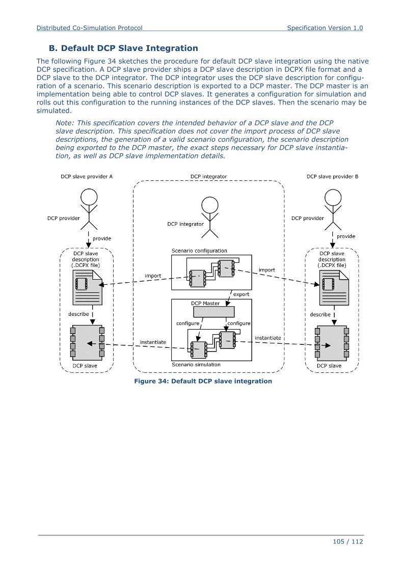
Distributed Co-Simulation Protocol Specification Version 1.0
105 / 112
B. Default DCP Slave Integration
The following Figure 34 sketches the procedure for default DCP slave integration using the native
DCP specification. A DCP slave provider ships a DCP slave description in DCPX file format and a
DCP slave to the DCP integrator. The DCP integrator uses the DCP slave description for configu-
ration of a scenario. This scenario description is exported to a DCP master. The DCP master is an
implementation being able to control DCP slaves. It generates a configuration for simulation and
rolls out this configuration to the running instances of the DCP slaves. Then the scenario may be
simulated.
Note: This specification covers the intended behavior of a DCP slave and the DCP
slave description. This specification does not cover the import process of DCP slave
descriptions, the generation of a valid scenario configuration, the scenario description
being exported to the DCP master, the exact steps necessary for DCP slave instantia-
tion, as well as DCP slave implementation details.
Figure 34: Default DCP slave integration
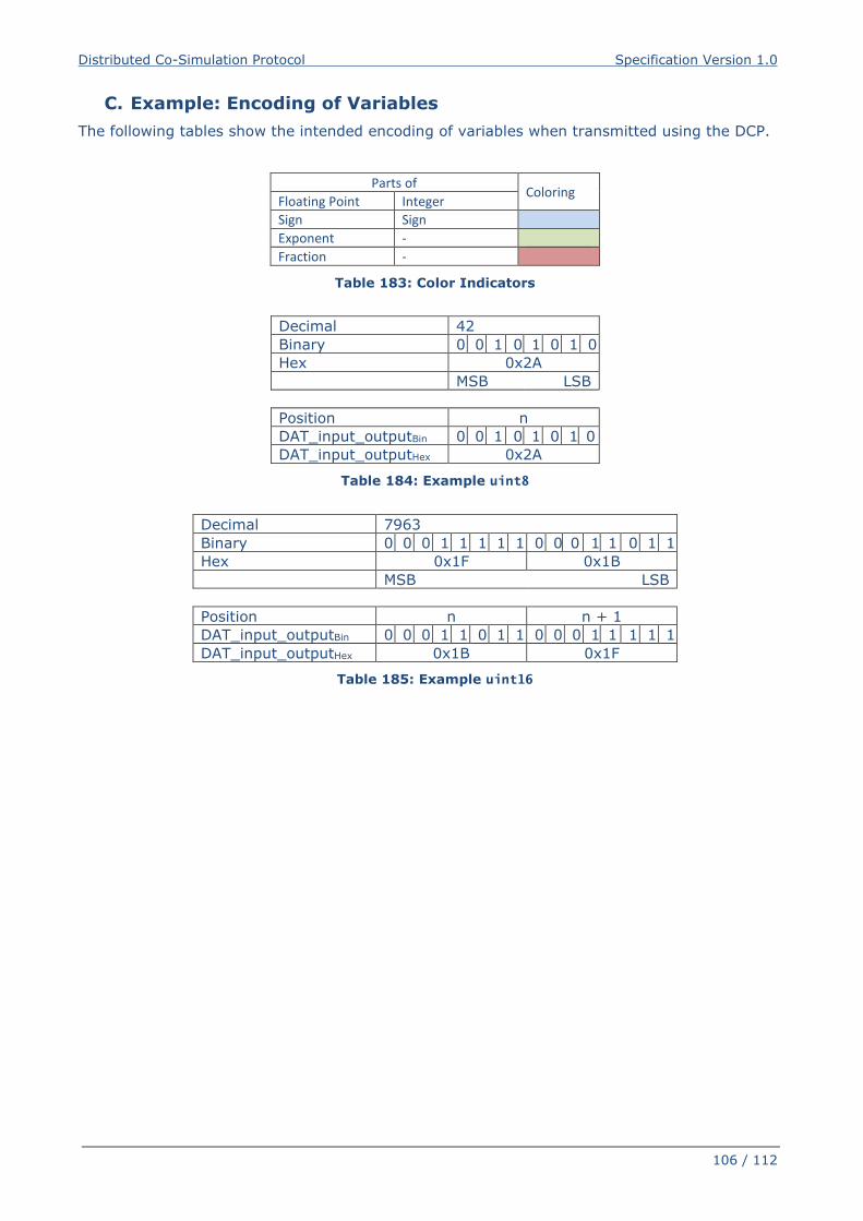
Distributed Co-Simulation Protocol Specification Version 1.0
106 / 112
C. Example: Encoding of Variables
The following tables show the intended encoding of variables when transmitted using the DCP.
Parts of Coloring
Floating Point Integer
Sign Sign
Exponent -
Fraction -
Table 183: Color Indicators
Decimal 42
Binary 0 0 1 0 1 0 1 0
Hex 0x2A
MSB LSB
Position n
DAT_input_outputBin 0 0 1 0 1 0 1 0
DAT_input_outputHex 0x2A
Table 184: Example uint8
Decimal 7963
Binary 0 0 0 1 1 1 1 1 0 0 0 1 1 0 1 1
Hex 0x1F 0x1B
MSB LSB
Position n n + 1
DAT_input_outputBin 0 0 0 1 1 0 1 1 0 0 0 1 1 1 1 1
DAT_input_outputHex 0x1B 0x1F
Table 185: Example uint16
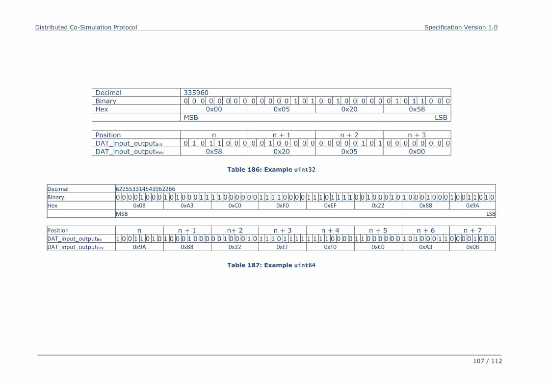
Distributed Co-Simulation Protocol Specification Version 1.0
107 / 112
Decimal 335960
Binary 0 0 0 0 0 0 0 0 0 0 0 0 0 1 0 1 0 0 1 0 0 0 0 0 0 1 0 1 1 0 0 0
Hex 0x00 0x05 0x20 0x58
MSB LSB
Position n n + 1 n + 2 n + 3
DAT_input_outputBin 0 1 0 1 1 0 0 0 0 0 1 0 0 0 0 0 0 0 0 0 0 1 0 1 0 0 0 0 0 0 0 0
DAT_input_outputHex 0x58 0x20 0x05 0x00
Table 186: Example uint32
Decimal 622553314543962266
Binary 0 0 0 0 1 0 0 0
0x08
1 0 1 0 0 0 1 1
0xA3
1 1 0 0 0 0 0 0
0xC0
1 1 1 1 0 0 0 0
0xF0
1 1 1 0 1 1 1 1
0xEF
0 0 1 0 0 0 1 0
0x22
1 0 0 0 1 0 0 0
0x88
1 0 0 1 1 0 1 0
0x9A
Hex
MSB LSB
Position n
1 0 0 1 1 0 1 0
0x9A
n + 1
1 0 0 0 1 0 0 0
0x88
n+ 2
0 0 1 0 0 0 1 0
0x22
n + 3
1 1 1 0 1 1 1 1
0xEF
n + 4
1 1 1 1 0 0 0 0
0xF0
n + 5
1 1 0 0 0 0 0 0
0xC0
n + 6
1 0 1 0 0 0 1 1
0xA3
n + 7
0 0 0 0 1 0 0 0
0x08
DAT_input_outputBin
DAT_input_outputHex
Table 187: Example uint64
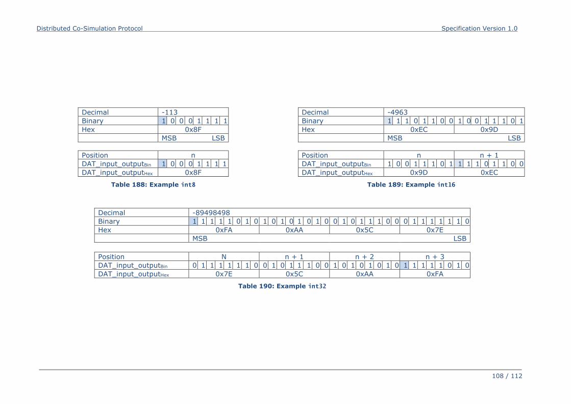
Distributed Co-Simulation Protocol Specification Version 1.0
108 / 112
Decimal -113
Binary 1 0 0 0 1 1 1 1
Hex 0x8F
MSB LSB
Position n
DAT_input_outputBin 1 0 0 0 1 1 1 1
DAT_input_outputHex 0x8F
Table 188: Example int8
Decimal -4963
Binary 1 1 1 0 1 1 0 0 1 0 0 1 1 1 0 1
Hex 0xEC 0x9D
MSB LSB
Position n n + 1
DAT_input_outputBin 1 0 0 1 1 1 0 1 1 1 1 0 1 1 0 0
DAT_input_outputHex 0x9D 0xEC
Table 189: Example int16
Decimal -89498498
Binary 1 1 1 1 1 0 1 0 1 0 1 0 1 0 1 0 0 1 0 1 1 1 0 0 0 1 1 1 1 1 1 0
Hex 0xFA 0xAA 0x5C 0x7E
MSB LSB
Position N n + 1 n + 2 n + 3
DAT_input_outputBin 0 1 1 1 1 1 1 0 0 1 0 1 1 1 0 0 1 0 1 0 1 0 1 0 1 1 1 1 1 0 1 0
DAT_input_outputHex 0x7E 0x5C 0xAA 0xFA
Table 190: Example int32
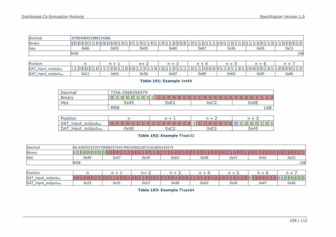
Distributed Co-Simulation Protocol Specification Version 1.0
109 / 112
Decimal -8789498491988154686
Binary 1 0 0 0 0 1 1 0
0x86
0 0 0 0 0 1 0 1
0x05
0 1 1 0 1 1 0 1
0x6D
1 0 1 1 0 0 0 0
0xB0
1 0 1 1 0 1 1 1
0xB7
0 0 1 1 0 1 1 0
0x36
1 1 1 0 0 1 1 0
0xE6
1 1 0 0 0 0 1 0
0xC2
Hex
MSB LSB
Position n
1 1 0 0 0 0 1 0
0xC2
n + 1
1 1 1 0 0 1 1 0
0xE6
n+ 2
0 0 1 1 0 1 1 0
0x36
n + 3
1 0 1 1 0 1 1 1
0xB7
n + 4
1 0 1 1 0 0 0 0
0xB0
n + 5
0 1 1 0 1 1 0 1
0x6D
n + 6
0 0 0 0 0 1 0 1
0x05
n + 7
1 0 0 0 0 1 1 0
0x86
DAT_input_outputBin
DAT_input_outputHex
Table 191: Example int64
Decimal 7256.2568359375
Binary 0 1 0 0 0 1 0 1 1 1 1 0 0 0 1 0 1 1 0 0 0 0 1 0 0 0 0 0 1 1 1 0
Hex 0x45 0xE2 0xC2 0x0E
MSB LSB
Position n n + 1 n + 2 n + 3
DAT_input_outputBin 0 0 0 0 1 1 1 0 1 1 0 0 0 0 1 0 1 1 1 0 0 0 1 0 0 1 0 0 0 1 0 1
DAT_input_outputHex 0x0E 0xC2 0xE3 0x45
Table 192: Example float32
Decimal 46.42829231507700882275457843206822872161865234375
Binary 0 1 0 0 0 0 0 0
0x40
0 1 0 0 0 1 1 1
0x47
0 0 1 1 0 1 1 0
0x36
1 1 0 1 0 0 1 0
0xD2
0 1 0 0 1 0 0 0
0x48
0 0 1 1 0 0 0 1
0x57
0 0 1 1 0 0 0 1
0x31
0 0 1 0 0 0 1 1
0x23
Hex
MSB LSB
Position n
0 0 1 0 0 0 1 1
0x23
n + 1
0 0 1 1 0 0 0 1
0x31
n+ 2
0 0 1 1 0 0 0 1
0x57
n + 3
0 1 0 0 1 0 0 0
0x48
n + 4
1 1 0 1 0 0 1 0
0xD2
n + 5
0 0 1 1 0 1 1 0
0x36
n + 6
0 1 0 0 0 1 1 1
0x47
n + 7
0 1 0 0 0 0 0 0
0x40
DAT_input_outputBin
DAT_input_outputHex
Table 193: Example float64
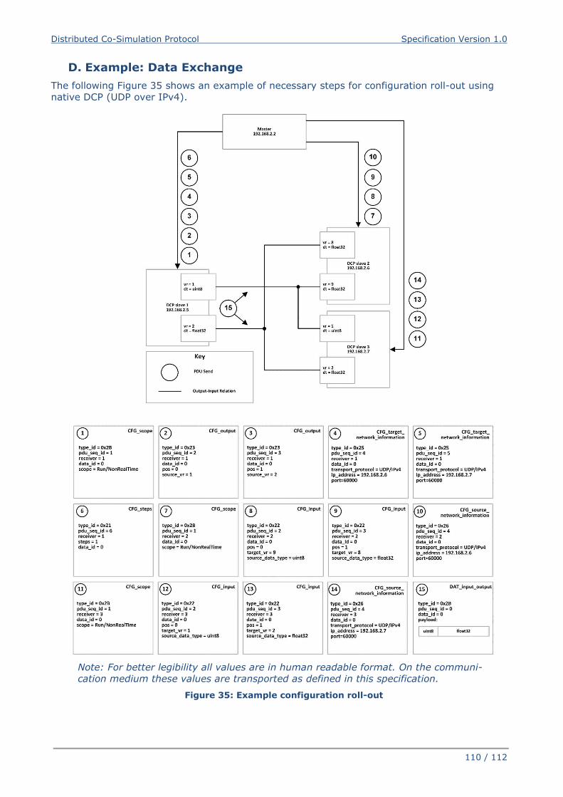
Distributed Co-Simulation Protocol Specification Version 1.0
110 / 112
D. Example: Data Exchange
The following Figure 35 shows an example of necessary steps for configuration roll-out using
native DCP (UDP over IPv4).
Note: For better legibility all values are in human readable format. On the communi-
cation medium these values are transported as defined in this specification.
Figure 35: Example configuration roll-out
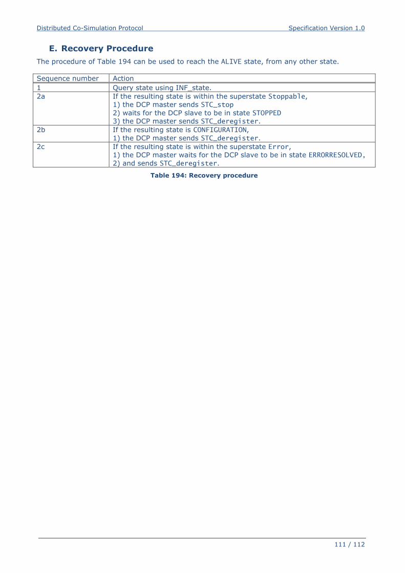
Distributed Co-Simulation Protocol Specification Version 1.0
111 / 112
E. Recovery Procedure
The procedure of Table 194 can be used to reach the ALIVE state, from any other state.
Sequence number Action
1 Query state using INF_state.
2a If the resulting state is within the superstate Stoppable,
1) the DCP master sends STC_stop
2) waits for the DCP slave to be in state STOPPED
3) the DCP master sends STC_deregister.
2b If the resulting state is CONFIGURATION,
1) the DCP master sends STC_deregister.
2c If the resulting state is within the superstate Error,
1) the DCP master waits for the DCP slave to be in state ERRORRESOLVED,
2) and sends STC_deregister.
Table 194: Recovery procedure
Distributed Co-Simulation Protocol Specification Version 1.0
112 / 112
F. General Guideline
Regarding the use of transport protocols related to Control PDUs:
It is recommended to use reliable transport protocols for Control PDUs.
Regarding the use of transport protocols related to continuous DAT_input_output PDUs:
Reliable transport protocols are considered beneficial if the time needed to transmit a
PDU, including time for retransmission, is in general lower than the specified DCP
communication step size.
Unreliable transport protocols are considered beneficial if e.g. higher network
throughput is required, or the target platform is only capable of supporting unreliable
transport protocols.
Regarding the use of transport protocols related to discrete DAT_input_output PDUs:
It is recommended to use reliable transport protocols for transmission of discrete Da-
ta PDUs.
Regarding the use of transport protocols related to DAT_parameter PDUs:
It is recommended to use reliable transport protocols for transmission of
DAT_parameter PDUs.
Regarding master implementations:
Implement the suggested procedure to transition slaves to a defined state.
Define behaviour after unexpected shutdown of DCP master.
Regarding master implementations based on unreliable transport protocols:
Retransmit Request PDUs if no acknowledgement is received.
Query states of slaves at regular intervals (use heartbeat mechanism).
Use DCP slaves implementing the maxConsecMissedPdu attribute, whenever possible.