Embed Size (px)
Citation preview
HT25 - SERVICE 1SERIAL NUMBER RECORD
SERVICE
SERIAL NUMBER RECORD
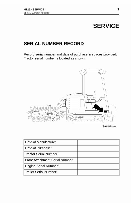
Record serial number and date of purchase in spaces provided. Tractor serial number is located as shown.
Date of Manufacture:
Date of Purchase:
Tractor Serial Number:
Front Attachment Serial Number:
Engine Serial Number:
Trailer Serial Number:
HT25 - SERVICE 1SERIAL NUMBER RECORD
SERVICE
SERIAL NUMBER RECORD
Record serial number and date of purchase in spaces provided. Tractor serial number is located as shown.
Date of Manufacture:
Date of Purchase:
Tractor Serial Number:
Front Attachment Serial Number:
Engine Serial Number:
Trailer Serial Number:

2 HT25 - SERVICESUPPORT PROCEDURE
2 HT25 - SERVICESUPPORT PROCEDURE
SUPPORT PROCEDURE
Notify your dealer immediately of any malfunction or failure of Ditch Witch equipment.
Always give model, serial number, and approximate date of equipment purchase. This information should be recorded and placed on file by owner at time of purchase.
Return damaged parts to dealer for inspection and Warranty consideration.
Order genuine Ditch Witch replacement or repair parts from your authorized Ditch Witch dealer. Use of another manufacturer's parts may void warranty.
RESOURCES
Publications
Contact your Ditch Witch dealer for publications covering operation, service, and repair of your equipment.
Ditch Witch TrainingFor information about on-site, individualized training, contact your Ditch Witch dealer.
SUP
Notify Ditch W
Alwaysequipmplaced
Returnconsid
Order authorparts m
RES
Publi
Contacoperat
DitchFor infDitch W
PORT PROCEDURE
your dealer immediately of any malfunction or failure of itch equipment.
give model, serial number, and approximate date of ent purchase. This information should be recorded and
on file by owner at time of purchase.
damaged parts to dealer for inspection and Warranty eration.
genuine Ditch Witch replacement or repair parts from your ized Ditch Witch dealer. Use of another manufacturer's ay void warranty.
OURCES
cations
t your Ditch Witch dealer for publications covering ion, service, and repair of your equipment.
Witch Trainingormation about on-site, individualized training, contact your
itch dealer.
HT25 - FOREWORD 3
FOREWORD
This manual is an important part of your equipment. It provides safety information and operation instructions to help you use and maintain your Ditch Witch equipment.
Read this manual before using your equipment. Keep it with the equipment at all times for future reference. If you sell your equipment, be sure to give this manual to the new owner.
If you need a replacement copy, contact your Ditch Witch dealer. If you need assistance in locating a dealer, visit our website at www.ditchwitch.com or write to the following address:
The Charles Machine Works, Inc. Attn: Marketing Department PO Box 66 Perry, OK 73077-0066 USA
The descriptions and specifications in this manual are subject to change. The Charles Machine Works, Inc. reserves the right to improve equipment. Some product improvements may have taken place after this manual was published. For the latest information on Ditch Witch equipment, see your Ditch Witch dealer.
Thank you for buying and using Ditch Witch equipment.

4 HT25 - FOREWORD 4 HT25 - FOREWORD
Operator's Manual
Issue Number 1.0/OP-4/00
Part Number 054-062
Copyright 2000
by The Charles Machine Works, Inc.,
Perry, Oklahoma
, Ditch Witch, Jet Trac, Pro Tech, Fluid Miser, Perma-Soil, Modularmatic, Roto Witch, AutoCrowd, and Subsite are registered trademarks of The Charles Machine Works, Inc.
CMW is a trademark of The Charles Machine Works, Inc.
Pierce Airrow is a registered trademark of Oklahoma Airrow, Inc.
Modulregiste
CMW
Pierce
Operator's Manual
Issue Number 1.0/OP-4/00
Part Number 054-062
Copyright 2000
by The Charles Machine Works, Inc.,
Perry, Oklahoma
, Ditch Witch, Jet Trac, Pro Tech, Fluid Miser, Perma-Soil, armatic, Roto Witch, AutoCrowd, and Subsite are red trademarks of The Charles Machine Works, Inc.
is a trademark of The Charles Machine Works, Inc.
Airrow is a registered trademark of Oklahoma Airrow, Inc.
HT25 - CONTENTS 5
CONTENTS
SERVICE . . . . . . . . . . . . . . . . . . . . . . . . . . . . . . . . . . . . . . . 1
Serial Number Record . . . . . . . . . . . . . . . . . . . . . . . . . 1
Support Procedure . . . . . . . . . . . . . . . . . . . . . . . . . . . . 2
Resources . . . . . . . . . . . . . . . . . . . . . . . . . . . . . . . . . . 2
FOREWORD . . . . . . . . . . . . . . . . . . . . . . . . . . . . . . . . . . . . 3
OVERVIEW . . . . . . . . . . . . . . . . . . . . . . . . . . . . . . . . . . . . . 9
CONTROLS . . . . . . . . . . . . . . . . . . . . . . . . . . . . . . . . . . . . 11
Overview. . . . . . . . . . . . . . . . . . . . . . . . . . . . . . . . . . . 11
Descriptions . . . . . . . . . . . . . . . . . . . . . . . . . . . . . . . . 12
SAFETY . . . . . . . . . . . . . . . . . . . . . . . . . . . . . . . . . . . . . . . 19
Accessories . . . . . . . . . . . . . . . . . . . . . . . . . . . . . . . . 20
Underground Hazards . . . . . . . . . . . . . . . . . . . . . . . . 20
Emergency Procedures . . . . . . . . . . . . . . . . . . . . . . . 21
Jobsite Classification . . . . . . . . . . . . . . . . . . . . . . . . . 24
Safety Alert Classifications . . . . . . . . . . . . . . . . . . . . . 28
Safety Alerts . . . . . . . . . . . . . . . . . . . . . . . . . . . . . . . . 29
HT25 - CONTENTS 5
CONTENTS
SERVICE . . . . . . . . . . . . . . . . . . . . . . . . . . . . . . . . . . . . . . . 1
Serial Number Record. . . . . . . . . . . . . . . . . . . . . . . . . . 1
Support Procedure . . . . . . . . . . . . . . . . . . . . . . . . . . . . 2
Resources . . . . . . . . . . . . . . . . . . . . . . . . . . . . . . . . . . . 2
FOREWORD. . . . . . . . . . . . . . . . . . . . . . . . . . . . . . . . . . . . . 3
OVERVIEW. . . . . . . . . . . . . . . . . . . . . . . . . . . . . . . . . . . . . . 9
CONTROLS . . . . . . . . . . . . . . . . . . . . . . . . . . . . . . . . . . . . 11
Overview . . . . . . . . . . . . . . . . . . . . . . . . . . . . . . . . . . . 11
Descriptions. . . . . . . . . . . . . . . . . . . . . . . . . . . . . . . . . 12
SAFETY . . . . . . . . . . . . . . . . . . . . . . . . . . . . . . . . . . . . . . . 19
Accessories . . . . . . . . . . . . . . . . . . . . . . . . . . . . . . . . . 20
Underground Hazards. . . . . . . . . . . . . . . . . . . . . . . . . 20
Emergency Procedures. . . . . . . . . . . . . . . . . . . . . . . . 21
Jobsite Classification. . . . . . . . . . . . . . . . . . . . . . . . . . 24
Safety Alert Classifications . . . . . . . . . . . . . . . . . . . . . 28
Safety Alerts . . . . . . . . . . . . . . . . . . . . . . . . . . . . . . . . 29
6 HT25 - CONTENTS 6 HT25 - CONTENTS
TRACTOR . . . . . . . . . . . . . . . . . . . . . . . . . . . . . . . . . . . . . 35
Daily Inspection . . . . . . . . . . . . . . . . . . . . . . . . . . . . . 35
Startup . . . . . . . . . . . . . . . . . . . . . . . . . . . . . . . . . . . . 36
Operation . . . . . . . . . . . . . . . . . . . . . . . . . . . . . . . . . . 38
Shutdown . . . . . . . . . . . . . . . . . . . . . . . . . . . . . . . . . . 38
TRANSPORTATION . . . . . . . . . . . . . . . . . . . . . . . . . . . . . 39
Lift . . . . . . . . . . . . . . . . . . . . . . . . . . . . . . . . . . . . . . . . 39
Tiedown . . . . . . . . . . . . . . . . . . . . . . . . . . . . . . . . . . . 40
Haul . . . . . . . . . . . . . . . . . . . . . . . . . . . . . . . . . . . . . . 41
Tow. . . . . . . . . . . . . . . . . . . . . . . . . . . . . . . . . . . . . . . 44
TRENCHING . . . . . . . . . . . . . . . . . . . . . . . . . . . . . . . . . . . 45
Control Overview . . . . . . . . . . . . . . . . . . . . . . . . . . . . 45
Control Descriptions . . . . . . . . . . . . . . . . . . . . . . . . . . 46
Setup . . . . . . . . . . . . . . . . . . . . . . . . . . . . . . . . . . . . . 47
Operation . . . . . . . . . . . . . . . . . . . . . . . . . . . . . . . . . . 49
Operating Tips . . . . . . . . . . . . . . . . . . . . . . . . . . . . . . 51
Optional Equipment . . . . . . . . . . . . . . . . . . . . . . . . . . 51
BACKHOE . . . . . . . . . . . . . . . . . . . . . . . . . . . . . . . . . . . . . 53
Control Overview . . . . . . . . . . . . . . . . . . . . . . . . . . . . 53
Control Descriptions . . . . . . . . . . . . . . . . . . . . . . . . . . 54
Setup . . . . . . . . . . . . . . . . . . . . . . . . . . . . . . . . . . . . . 56
Operation . . . . . . . . . . . . . . . . . . . . . . . . . . . . . . . . . . 57
TRAC
D
S
O
S
TRAN
L
T
H
T
TREN
C
C
S
O
O
O
BACK
C
C
S
O
TOR . . . . . . . . . . . . . . . . . . . . . . . . . . . . . . . . . . . . . 35
aily Inspection . . . . . . . . . . . . . . . . . . . . . . . . . . . . . 35
tartup . . . . . . . . . . . . . . . . . . . . . . . . . . . . . . . . . . . . 36
peration . . . . . . . . . . . . . . . . . . . . . . . . . . . . . . . . . . 38
hutdown . . . . . . . . . . . . . . . . . . . . . . . . . . . . . . . . . . 38
SPORTATION . . . . . . . . . . . . . . . . . . . . . . . . . . . . . 39
ift . . . . . . . . . . . . . . . . . . . . . . . . . . . . . . . . . . . . . . . 39
iedown . . . . . . . . . . . . . . . . . . . . . . . . . . . . . . . . . . . 40
aul . . . . . . . . . . . . . . . . . . . . . . . . . . . . . . . . . . . . . . 41
ow . . . . . . . . . . . . . . . . . . . . . . . . . . . . . . . . . . . . . . 44
CHING . . . . . . . . . . . . . . . . . . . . . . . . . . . . . . . . . . . 45
ontrol Overview . . . . . . . . . . . . . . . . . . . . . . . . . . . . 45
ontrol Descriptions. . . . . . . . . . . . . . . . . . . . . . . . . . 46
etup . . . . . . . . . . . . . . . . . . . . . . . . . . . . . . . . . . . . . 47
peration . . . . . . . . . . . . . . . . . . . . . . . . . . . . . . . . . . 49
perating Tips . . . . . . . . . . . . . . . . . . . . . . . . . . . . . . 51
ptional Equipment . . . . . . . . . . . . . . . . . . . . . . . . . . 51
HOE. . . . . . . . . . . . . . . . . . . . . . . . . . . . . . . . . . . . . 53
ontrol Overview . . . . . . . . . . . . . . . . . . . . . . . . . . . . 53
ontrol Descriptions. . . . . . . . . . . . . . . . . . . . . . . . . . 54
etup . . . . . . . . . . . . . . . . . . . . . . . . . . . . . . . . . . . . . 56
peration . . . . . . . . . . . . . . . . . . . . . . . . . . . . . . . . . . 57
HT25 - CONTENTS 7
LUBRICATION. . . . . . . . . . . . . . . . . . . . . . . . . . . . . . . . . . 59
Overview. . . . . . . . . . . . . . . . . . . . . . . . . . . . . . . . . . . 60
Schedule. . . . . . . . . . . . . . . . . . . . . . . . . . . . . . . . . . . 61
Engine . . . . . . . . . . . . . . . . . . . . . . . . . . . . . . . . . . . . 62
Ground Drive . . . . . . . . . . . . . . . . . . . . . . . . . . . . . . . 64
Hydraulics. . . . . . . . . . . . . . . . . . . . . . . . . . . . . . . . . . 66
Trencher . . . . . . . . . . . . . . . . . . . . . . . . . . . . . . . . . . . 68
Backfill Blade . . . . . . . . . . . . . . . . . . . . . . . . . . . . . . . 71
MAINTENANCE. . . . . . . . . . . . . . . . . . . . . . . . . . . . . . . . . 73
Overview . . . . . . . . . . . . . . . . . . . . . . . . . . . . . . . . . . 74
Engine . . . . . . . . . . . . . . . . . . . . . . . . . . . . . . . . . . . . 75
Ground Drive . . . . . . . . . . . . . . . . . . . . . . . . . . . . . . . 80
Hydraulics. . . . . . . . . . . . . . . . . . . . . . . . . . . . . . . . . . 83
Electrical . . . . . . . . . . . . . . . . . . . . . . . . . . . . . . . . . . . 84
Trencher . . . . . . . . . . . . . . . . . . . . . . . . . . . . . . . . . . . 85
SPECIFICATIONS . . . . . . . . . . . . . . . . . . . . . . . . . . . . . . . 93
HT25. . . . . . . . . . . . . . . . . . . . . . . . . . . . . . . . . . . . . . 93
A225 Backhoe . . . . . . . . . . . . . . . . . . . . . . . . . . . . . . 97
HT25 - CONTENTS 7
LUBRICATION . . . . . . . . . . . . . . . . . . . . . . . . . . . . . . . . . . 59
Overview . . . . . . . . . . . . . . . . . . . . . . . . . . . . . . . . . . . 60
Schedule . . . . . . . . . . . . . . . . . . . . . . . . . . . . . . . . . . . 61
Engine . . . . . . . . . . . . . . . . . . . . . . . . . . . . . . . . . . . . . 62
Ground Drive . . . . . . . . . . . . . . . . . . . . . . . . . . . . . . . . 64
Hydraulics . . . . . . . . . . . . . . . . . . . . . . . . . . . . . . . . . . 66
Trencher . . . . . . . . . . . . . . . . . . . . . . . . . . . . . . . . . . . 68
Backfill Blade. . . . . . . . . . . . . . . . . . . . . . . . . . . . . . . . 71
MAINTENANCE . . . . . . . . . . . . . . . . . . . . . . . . . . . . . . . . . 73
Overview . . . . . . . . . . . . . . . . . . . . . . . . . . . . . . . . . . 74
Engine . . . . . . . . . . . . . . . . . . . . . . . . . . . . . . . . . . . . . 75
Ground Drive . . . . . . . . . . . . . . . . . . . . . . . . . . . . . . . . 80
Hydraulics . . . . . . . . . . . . . . . . . . . . . . . . . . . . . . . . . . 83
Electrical . . . . . . . . . . . . . . . . . . . . . . . . . . . . . . . . . . . 84
Trencher . . . . . . . . . . . . . . . . . . . . . . . . . . . . . . . . . . . 85
SPECIFICATIONS . . . . . . . . . . . . . . . . . . . . . . . . . . . . . . . 93
HT25 . . . . . . . . . . . . . . . . . . . . . . . . . . . . . . . . . . . . . . 93
A225 Backhoe. . . . . . . . . . . . . . . . . . . . . . . . . . . . . . . 97

8 HT25 - CONTENTS 8 HT25 - CONTENTS
HT25 - OVERVIEW 9
OVERVIEW
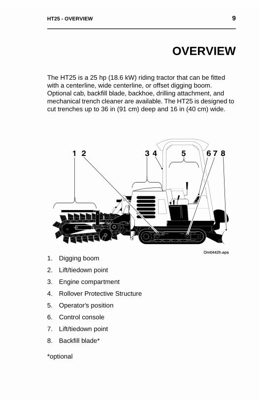
The HT25 is a 25 hp (18.6 kW) riding tractor that can be fitted with a centerline, wide centerline, or offset digging boom. Optional cab, backfill blade, backhoe, drilling attachment, and mechanical trench cleaner are available. The HT25 is designed to cut trenches up to 36 in (91 cm) deep and 16 in (40 cm) wide.
1. Digging boom
2. Lift/tiedown point
3. Engine compartment
4. Rollover Protective Structure
5. Operator’s position
6. Control console
7. Lift/tiedown point
8. Backfill blade*
*optional
HT25 - OVERVIEW 9
OVERVIEW
The HT25 is a 25 hp (18.6 kW) riding tractor that can be fitted with a centerline, wide centerline, or offset digging boom. Optional cab, backfill blade, backhoe, drilling attachment, and mechanical trench cleaner are available. The HT25 is designed to cut trenches up to 36 in (91 cm) deep and 16 in (40 cm) wide.
1. Digging boom
2. Lift/tiedown point
3. Engine compartment
4. Rollover Protective Structure
5. Operator’s position
6. Control console
7. Lift/tiedown point
8. Backfill blade*
*optional

10 HT25 - OVERVIEW 10 HT25 - OVERVIEW
HT25 - CONTROLS 11OVERVIEW
CONTROLS
OVERVIEW
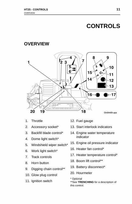
1. Throttle
2. Accessory socket*
3. Backfill blade control*
4. Dome light switch*
5. Windshield wiper switch*
6. Work light switch*
7. Track controls
8. Horn button
9. Digging chain control**
10. Glow plug control
11. Ignition switch
12. Fuel gauge
13. Start interlock indicators
14. Engine water temperature indicator
15. Engine oil pressure indicator
16. Heater fan control*
17. Heater temperature control*
18. Boom lift control**
19. Battery disconnect*
20. Hourmeter
* Optional**See TRENCHING for a description of this control.
HT25 - CONTROLS 11OVERVIEW
CONTROLS
OVERVIEW
1. Throttle
2. Accessory socket*
3. Backfill blade control*
4. Dome light switch*
5. Windshield wiper switch*
6. Work light switch*
7. Track controls
8. Horn button
9. Digging chain control**
10. Glow plug control
11. Ignition switch
12. Fuel gauge
13. Start interlock indicators
14. Engine water temperature indicator
15. Engine oil pressure indicator
16. Heater fan control*
17. Heater temperature control*
18. Boom lift control**
19. Battery disconnect*
20. Hourmeter
* Optional**See TRENCHING for a description of this control.
12 HT25 - CONTROLSDESCRIPTIONS
12 HT25 - CONTROLSDESCRIPTIONS
DESCRIPTIONS
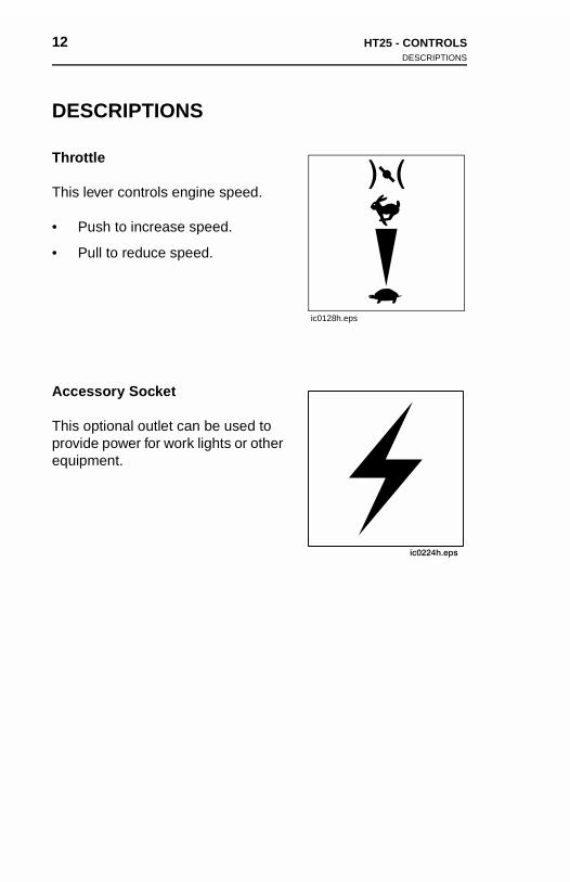
Throttle
This lever controls engine speed.
• Push to increase speed.
• Pull to reduce speed.
Accessory Socket
This optional outlet can be used to provide power for work lights or other equipment.
ic0128h.eps
DES
Thrott
This le
• Pu
• Pu
Acces
This oprovidequipm
CRIPTIONS
le
ver controls engine speed.
sh to increase speed.
ll to reduce speed.
sory Socket
ptional outlet can be used to e power for work lights or other
ent.
ic0128h.eps

HT25 - CONTROLS 13DESCRIPTIONS
Backfill Blade Control
This optional lever raises, lowers, and swings backfill blade.
• Push to lower blade.
• Pull to raise blade.
• Move right to swing blade right.
• Move left to swing blade left.
Work Light Switch
This optional switch controls front and rear work lights.
• Press right to turn on.
• Press left to turn off.
Dome Light Switch
This optional button controls interior dome light.
• Press top to turn on.
• Press bottom to turn off.
14 HT25 - CONTROLSDESCRIPTIONS
14 HT25 - CONTROLSDESCRIPTIONS
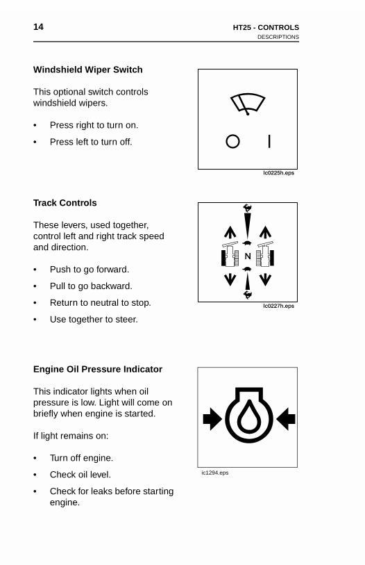
Windshield Wiper Switch
This optional switch controls windshield wipers.
• Press right to turn on.
• Press left to turn off.
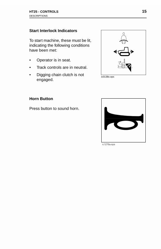
Track Controls
These levers, used together, control left and right track speed and direction.
• Push to go forward.
• Pull to go backward.
• Return to neutral to stop.
• Use together to steer.
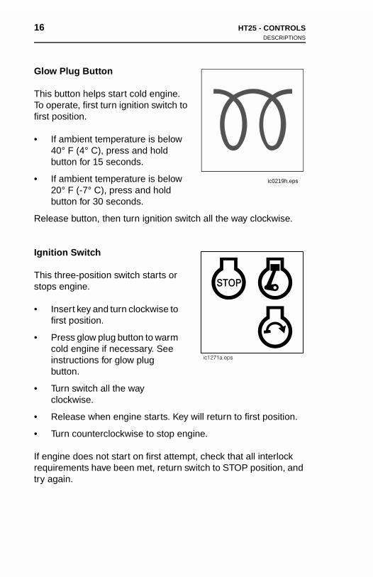
Engine Oil Pressure Indicator
This indicator lights when oil pressure is low. Light will come on briefly when engine is started.
If light remains on:
• Turn off engine.
• Check oil level.
• Check for leaks before starting engine.
Ic0225h.eps
Ic0227h.eps
ic1294.eps
Winds
This owindsh
• Pr
• Pr
Track
Thesecontroand di
• Pu
• Pu
• Re
• Us
Engin
This inpressubriefly
If light
• Tu
• Ch
• Chen
hield Wiper Switch
ptional switch controls ield wipers.
ess right to turn on.
ess left to turn off.
Controls
levers, used together, l left and right track speed rection.
sh to go forward.
ll to go backward.
turn to neutral to stop.
e together to steer.
Ic0225h.eps
Ic0227h.eps
e Oil Pressure Indicator
dicator lights when oil re is low. Light will come on when engine is started.
remains on:
rn off engine.
eck oil level.
eck for leaks before starting gine.
ic1294.eps
HT25 - CONTROLS 15DESCRIPTIONS
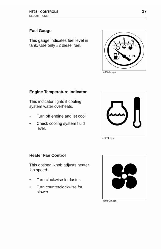
Start Interlock Indicators
To start machine, these must be lit, indicating the following conditions have been met:
• Operator is in seat.
• Track controls are in neutral.
• Digging chain clutch is not engaged.
Horn Button
Press button to sound horn.
ic0138x.eps
HT25 - CONTROLS 15DESCRIPTIONS
Start Interlock Indicators
To start machine, these must be lit, indicating the following conditions have been met:
• Operator is in seat.
• Track controls are in neutral.
• Digging chain clutch is not engaged.
Horn Button
Press button to sound horn.
ic0138x.eps
16 HT25 - CONTROLSDESCRIPTIONS
16 HT25 - CONTROLSDESCRIPTIONS
Glow Plug Button
This button helps start cold engine. To operate, first turn ignition switch to first position.
• If ambient temperature is below 40° F (4° C), press and hold button for 15 seconds.
• If ambient temperature is below 20° F (-7° C), press and hold button for 30 seconds.
Release button, then turn ignition switch all the way clockwise.
Ignition Switch
This three-position switch starts or stops engine.
• Insert key and turn clockwise to first position.
• Press glow plug button to warm cold engine if necessary. See instructions for glow plug button.
• Turn switch all the way clockwise.
• Release when engine starts. Key will return to first position.
• Turn counterclockwise to stop engine.
If engine does not start on first attempt, check that all interlock requirements have been met, return switch to STOP position, and try again.
ic0219h.eps
Glow
This bTo opefirst po
• If a40bu
• If a20bu
Releas
Ignitio
This thstops e
• Insfirs
• Prcoinsbu
• Tuclo
• Re
• Tu
If engirequiretry aga
Plug Button
utton helps start cold engine. rate, first turn ignition switch to sition.
mbient temperature is below ° F (4° C), press and hold tton for 15 seconds.
mbient temperature is below ° F (-7° C), press and hold tton for 30 seconds.
e button, then turn ignition switch all the way clockwise.
n Switch
ree-position switch starts or ngine.
ert key and turn clockwise to t position.
ess glow plug button to warm
ic0219h.eps
ld engine if necessary. See tructions for glow plug tton.
rn switch all the way ckwise.
lease when engine starts. Key will return to first position.
rn counterclockwise to stop engine.
ne does not start on first attempt, check that all interlock ments have been met, return switch to STOP position, and in.
HT25 - CONTROLS 17DESCRIPTIONS
Fuel Gauge
This gauge indicates fuel level in tank. Use only #2 diesel fuel.
Engine Temperature Indicator
This indicator lights if cooling system water overheats.
• Turn off engine and let cool.
• Check cooling system fluid level.
Heater Fan Control
This optional knob adjusts heater fan speed.
• Turn clockwise for faster.
• Turn counterclockwise for slower.
ic1274.eps
18 HT25 - CONTROLSDESCRIPTIONS
18 HT25 - CONTROLSDESCRIPTIONS
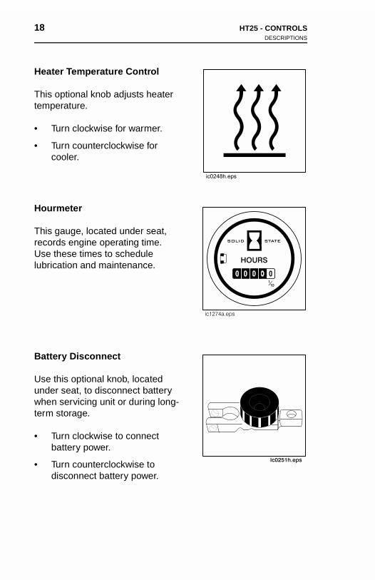
Heater Temperature Control
This optional knob adjusts heater temperature.
• Turn clockwise for warmer.
• Turn counterclockwise for cooler.
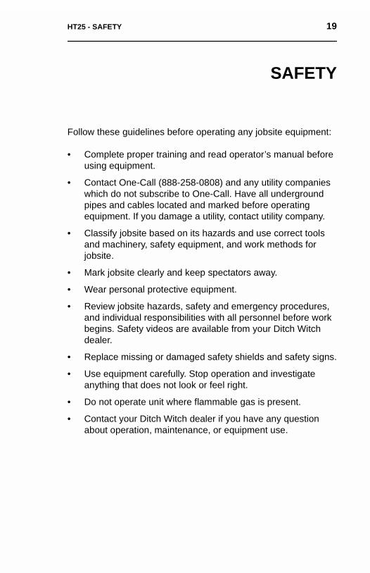
Hourmeter
This gauge, located under seat, records engine operating time. Use these times to schedule lubrication and maintenance.
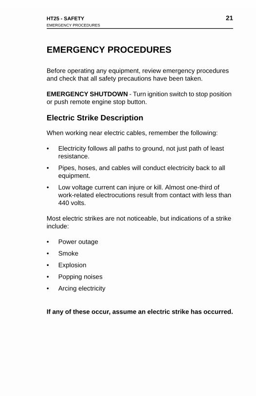
Battery Disconnect
Use this optional knob, located under seat, to disconnect battery when servicing unit or during long-term storage.
• Turn clockwise to connect battery power.
• Turn counterclockwise to disconnect battery power.
Heate
This otempe
• Tu
• Tuco
Hourm
This grecordUse thlubrica
Batter
Use thunder when sterm s
• Tuba
• Tudis
r Temperature Control
ptional knob adjusts heater rature.
rn clockwise for warmer.
rn counterclockwise for oler.
eter
auge, located under seat, s engine operating time. ese times to schedule tion and maintenance.
y Disconnect
is optional knob, located seat, to disconnect battery ervicing unit or during long-
torage.
rn clockwise to connect ttery power.
rn counterclockwise to connect battery power.
HT25 - SAFETY 19
SAFETY
Follow these guidelines before operating any jobsite equipment:
• Complete proper training and read operator’s manual before using equipment.
• Contact One-Call (888-258-0808) and any utility companies which do not subscribe to One-Call. Have all underground pipes and cables located and marked before operating equipment. If you damage a utility, contact utility company.
• Classify jobsite based on its hazards and use correct tools and machinery, safety equipment, and work methods for jobsite.
• Mark jobsite clearly and keep spectators away.
• Wear personal protective equipment.
• Review jobsite hazards, safety and emergency procedures, and individual responsibilities with all personnel before work begins. Safety videos are available from your Ditch Witch dealer.
• Replace missing or damaged safety shields and safety signs.
• Use equipment carefully. Stop operation and investigate anything that does not look or feel right.
• Do not operate unit where flammable gas is present.
• Contact your Ditch Witch dealer if you have any question about operation, maintenance, or equipment use.
HT25 - SAFETY 19
SAFETY
Follow these guidelines before operating any jobsite equipment:
• Complete proper training and read operator’s manual before using equipment.
• Contact One-Call (888-258-0808) and any utility companies which do not subscribe to One-Call. Have all underground pipes and cables located and marked before operating equipment. If you damage a utility, contact utility company.
• Classify jobsite based on its hazards and use correct tools and machinery, safety equipment, and work methods for jobsite.
• Mark jobsite clearly and keep spectators away.
• Wear personal protective equipment.
• Review jobsite hazards, safety and emergency procedures,
and individual responsibilities with all personnel before work begins. Safety videos are available from your Ditch Witch dealer.• Replace missing or damaged safety shields and safety signs.
• Use equipment carefully. Stop operation and investigate anything that does not look or feel right.
• Do not operate unit where flammable gas is present.
• Contact your Ditch Witch dealer if you have any question about operation, maintenance, or equipment use.

20 HT25 - SAFETYACCESSORIES
20 HT25 - SAFETYACCESSORIES
ACCESSORIES
Fire Extinguisher
If required, a fire extinguisher should be mounted near the power unit but away from possible points of ignition. The fire extinguisher should always be classified for both oil and electric fires. It should meet legal and regulatory requirements.
Lighting Kit
If you need additional light, plug lighting kit into provided outlet. Contact your Ditch Witch dealer for further information.
UNDERGROUND HAZARDS
Striking underground hazards can cause explosion, electrocution, fire, and exposure to hazardous materials.
Hazards include:
• Electric lines
• Natural gas lines
• Fiber optic cables
• Water lines
• Sewer lines
• Pipes carrying other chemicals, liquids, or gases
• Storage tanks
ACC
Fire E
If requunit buextingufires. I
Light
If you Contac
UND
Strikinfire, an
Hazard
• Ele
• Na
• Fib
• W
• Se
• Pip
• St
ESSORIES
xtinguisher
ired, a fire extinguisher should be mounted near the power t away from possible points of ignition. The fire isher should always be classified for both oil and electric
t should meet legal and regulatory requirements.
ing Kit
need additional light, plug lighting kit into provided outlet. t your Ditch Witch dealer for further information.
ERGROUND HAZARDS
g underground hazards can cause explosion, electrocution, d exposure to hazardous materials.
s include:
ctric lines
tural gas lines
er optic cables
ater lines
wer lines
es carrying other chemicals, liquids, or gases
orage tanks
HT25 - SAFETY 21EMERGENCY PROCEDURES
EMERGENCY PROCEDURES
Before operating any equipment, review emergency procedures and check that all safety precautions have been taken.
EMERGENCY SHUTDOWN - Turn ignition switch to stop position or push remote engine stop button.
Electric Strike Description
When working near electric cables, remember the following:
• Electricity follows all paths to ground, not just path of least resistance.
• Pipes, hoses, and cables will conduct electricity back to all equipment.
• Low voltage current can injure or kill. Almost one-third of work-related electrocutions result from contact with less than 440 volts.
Most electric strikes are not noticeable, but indications of a strike include:
• Power outage
• Smoke
• Explosion
• Popping noises
• Arcing electricity
If any of these occur, assume an electric strike has occurred.
22 HT25 - SAFETYEMERGENCY PROCEDURES
22 HT25 - SAFETYEMERGENCY PROCEDURES
If an Electric Line is Damaged
On Tractor
1. DO NOT MOVE. Remain on tractor.
2. Warn people nearby that an electric strike has occurred. Instruct them to leave the area and contact utility.
3. Raise attachments and drive from immediate area.
4. Contact utility company to shut off power.
5. Do not return to area or allow anyone into area until given permission by utility company.
Off Tractor
1. DO NOT TOUCH ANY EQUIPMENT.
2. LEAVE AREA.
3. Contact utility company to shut off power.
4. Do not return to area or allow anyone into area until given permission by utility company.
If an
On Tra
1. DO
2. WIns
3. Ra
4. Co
5. Dope
Off Tra
1. DO
2. LE
3. Co
4. Dope
Electric Line is Damaged
ctor
NOT MOVE. Remain on tractor.
arn people nearby that an electric strike has occurred. truct them to leave the area and contact utility.
ise attachments and drive from immediate area.
ntact utility company to shut off power.
not return to area or allow anyone into area until given rmission by utility company.
ctor
NOT TOUCH ANY EQUIPMENT.
AVE AREA.
ntact utility company to shut off power.
not return to area or allow anyone into area until given rmission by utility company.

HT25 - SAFETY 23EMERGENCY PROCEDURES
If a Gas Line is Damaged1. Immediately shut off engine(s) and remove any ignition
sources.
2. LEAVE AREA as quickly as possible.
3. Warn others that a gas line has been cut and that they should leave area.
4. Contact emergency personnel.
5. Contact utility company.
6. Do not return to area until given permission by utility company.
If a Fiber Optic Cable is Damaged
Do not look into cut ends of fiber optic or unidentified cable. Vision damage can occur.
24 HT25 - SAFETYJOBSITE CLASSIFICATION
24 HT25 - SAFETYJOBSITE CLASSIFICATION
JOBSITE CLASSIFICATION
Inspecting Jobsite• Follow U.S. Department of Labor regulations on excavating
and trenching (Part 1926, Subpart P) and other similar regulations.
• Contact One-Call (888-258-0808) and any utility companies which do not subscribe to One-Call.
• Inspect jobsite and perimeter for evidence of underground hazards, such as:
– “Buried utility” notices
– Utility facilities without overhead lines
– Gas or water meters
– Junction boxes
– Drop boxes
– Light poles
– Manhole covers
– Sunken ground
• Have an experienced locating equipment operator sweep area within 20 feet (6 m) to each side of trench path. Verify previously marked line and cable locations.
• Mark location of all buried utilities and obstructions.
• Classify jobsite.
JOB
Inspe• Fo
anreg
• Cowh
• Insha
– “
– U
– G
– J
– D
– L
– M
– S
• Haarepre
• Ma
• Cl
SITE CLASSIFICATION
cting Jobsitellow U.S. Department of Labor regulations on excavating d trenching (Part 1926, Subpart P) and other similar ulations.
ntact One-Call (888-258-0808) and any utility companies ich do not subscribe to One-Call.
pect jobsite and perimeter for evidence of underground zards, such as:
Buried utility” notices
tility facilities without overhead lines
as or water meters
unction boxes
rop boxes
ight poles
anhole covers
unken ground
ve an experienced locating equipment operator sweep
a within 20 feet (6 m) to each side of trench path. Verify viously marked line and cable locations.rk location of all buried utilities and obstructions.
assify jobsite.
HT25 - SAFETY 25JOBSITE CLASSIFICATION
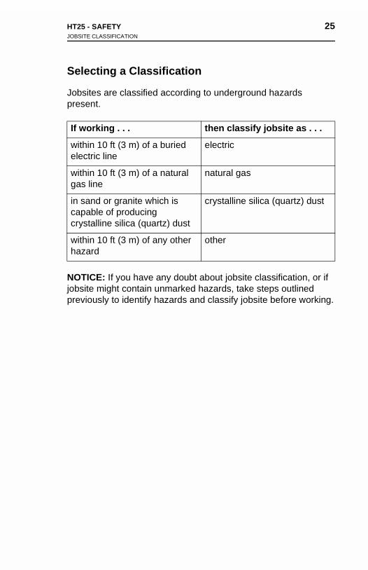
Selecting a Classification
Jobsites are classified according to underground hazards present.
NOTICE: If you have any doubt about jobsite classification, or if jobsite might contain unmarked hazards, take steps outlined previously to identify hazards and classify jobsite before working.
If working . . . then classify jobsite as . . .
within 10 ft (3 m) of a buried electric line
electric
within 10 ft (3 m) of a natural gas line
natural gas
in sand or granite which is capable of producing crystalline silica (quartz) dust
crystalline silica (quartz) dust
within 10 ft (3 m) of any other hazard
other
HT25 - SAFETY 25JOBSITE CLASSIFICATION
Selecting a Classification
Jobsites are classified according to underground hazards present.
NOTICE: If you have any doubt about jobsite classification, or if jobsite might contain unmarked hazards, take steps outlined previously to identify hazards and classify jobsite before working.
If working . . . then classify jobsite as . . .
within 10 ft (3 m) of a buried electric line
electric
within 10 ft (3 m) of a natural gas line
natural gas
in sand or granite which is capable of producing crystalline silica (quartz) dust
crystalline silica (quartz) dust
within 10 ft (3 m) of any other hazard
other
26 HT25 - SAFETYJOBSITE CLASSIFICATION
26 HT25 - SAFETYJOBSITE CLASSIFICATION
Applying Precautions
Once classified, precautions appropriate for jobsite must be taken.
Electric Jobsite Precautions
Use one or both of these methods.
• Expose line by careful hand digging or soft excavation.
• Have service shut down while work is in progress. Have electric company test lines before returning them to service.
Natural Gas Jobsite Precautions
In addition to positioning equipment upwind from gas lines, use one or both of these methods.
• Expose lines by careful hand digging or soft excavation.
• Have gas shut off while work is in progress. Have gas company test lines before returning them to service.
Apply
Once ctaken.
Electr
Use on
• Ex
• Haele
Natura
In addone or
• Ex
• Haco
ing Precautions
lassified, precautions appropriate for jobsite must be
ic Jobsite Precautions
e or both of these methods.
pose line by careful hand digging or soft excavation.
ve service shut down while work is in progress. Have ctric company test lines before returning them to service.
l Gas Jobsite Precautions
ition to positioning equipment upwind from gas lines, use both of these methods.
pose lines by careful hand digging or soft excavation.
ve gas shut off while work is in progress. Have gas
mpany test lines before returning them to service.
HT25 - SAFETY 27JOBSITE CLASSIFICATION
Crystalline Silica (Quartz) Dust
Follow these guidelines when trenching, sawing or drilling through material that might produce dust containing crystalline silica (quartz) dust.
1. Know the work operations where exposure to crystalline silica may occur. Be aware of health effects of crystallline silica and that smoking adds to the damage.
2. Follow OSHA (or other) guidelines for exposure to airborne crystalline silica. Participate in air monitoring or training programs offered by employer.
3. Be aware of and use available engineering controls such as water sprays, local exhaust ventilation, and enclosed cabs with positive pressure air conditioning.
4. Where respirators are required, wear one approved for protection against crystalline silica-containing dust. Do not alter respirator in any way. Workers using tight-fitting respirators cannot have beards/mustaches which interfere with respirator’s seal to the face.
5. If possible, change into disposable or washable work clothes at jobsite; shower and change into clean clothing before leaving jobsite.
6. Do not eat, drink, use tobacco products, or apply cosmetics in areas where there is dust containing crystalline silica. Wash hands and face before eating, drinking, smoking, or applying cosmetics outside exposure area.
7. Store food, drink, and personal belongings away from work area.
Other Jobsite Precautions
You may need to use different methods to safely avoid other underground hazards. Talk with those responsible for hazards to determine which precautions should be taken or if job should be attempted.
28 HT25 - SAFETYSAFETY ALERT CLASSIFICATIONS
28 HT25 - SAFETYSAFETY ALERT CLASSIFICATIONS
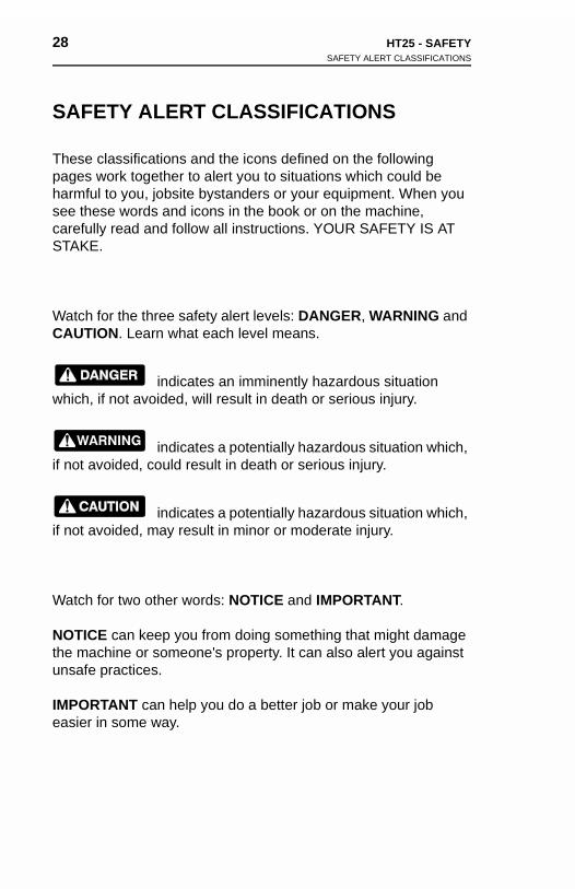
SAFETY ALERT CLASSIFICATIONS
These classifications and the icons defined on the following pages work together to alert you to situations which could be harmful to you, jobsite bystanders or your equipment. When you see these words and icons in the book or on the machine, carefully read and follow all instructions. YOUR SAFETY IS AT STAKE.
Watch for the three safety alert levels: DANGER, WARNING and CAUTION. Learn what each level means.
indicates an imminently hazardous situation which, if not avoided, will result in death or serious injury.
indicates a potentially hazardous situation which, if not avoided, could result in death or serious injury.
indicates a potentially hazardous situation which, if not avoided, may result in minor or moderate injury.
Watch for two other words: NOTICE and IMPORTANT.
NOTICE can keep you from doing something that might damage the machine or someone's property. It can also alert you against unsafe practices.
IMPORTANT can help you do a better job or make your job easier in some way.
SAF
Thesepagesharmfusee thcarefuSTAKE
WatchCAUT
which,
if not a
if not a
Watch
NOTICthe maunsafe
IMPOReasier
ETY ALERT CLASSIFICATIONS
classifications and the icons defined on the following work together to alert you to situations which could be l to you, jobsite bystanders or your equipment. When you
ese words and icons in the book or on the machine, lly read and follow all instructions. YOUR SAFETY IS AT .
for the three safety alert levels: DANGER, WARNING and ION. Learn what each level means.
indicates an imminently hazardous situation if not avoided, will result in death or serious injury.
indicates a potentially hazardous situation which, voided, could result in death or serious injury.
indicates a potentially hazardous situation which, voided, may result in minor or moderate injury.
for two other words: NOTICE and IMPORTANT.
E can keep you from doing something that might damage chine or someone's property. It can also alert you against practices.
TANT can help you do a better job or make your job in some way.
HT25 - SAFETY 29SAFETY ALERTS
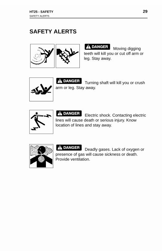
SAFETY ALERTS
Moving digging teeth will kill you or cut off arm or leg. Stay away.
Turning shaft will kill you or crush arm or leg. Stay away.
Electric shock. Contacting electric lines will cause death or serious injury. Know location of lines and stay away.
Deadly gases. Lack of oxygen or presence of gas will cause sickness or death. Provide ventilation.
HT25 - SAFETY 29SAFETY ALERTS
SAFETY ALERTS
Moving digging teeth will kill you or cut off arm or leg. Stay away.
Turning shaft will kill you or crush arm or leg. Stay away.
Electric shock. Contacting electric lines will cause death or serious injury. Know location of lines and stay away.
Deadly gases. Lack of oxygen or presence of gas will cause sickness or death. Provide ventilation.
30 HT25 - SAFETYSAFETY ALERTS
30 HT25 - SAFETYSAFETY ALERTS
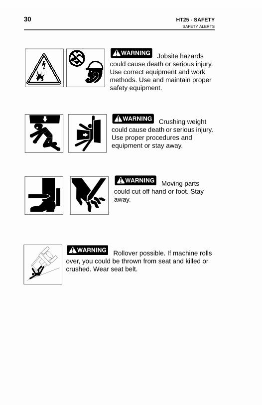
Jobsite hazards could cause death or serious injury. Use correct equipment and work methods. Use and maintain proper safety equipment.
Crushing weight could cause death or serious injury. Use proper procedures and equipment or stay away.
Moving parts could cut off hand or foot. Stay away.
Rollover possible. If machine rolls over, you could be thrown from seat and killed or crushed. Wear seat belt.
HT25 - SAFETY 31SAFETY ALERTS
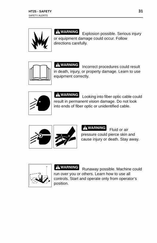
Explosion possible. Serious injury or equipment damage could occur. Follow directions carefully.
Incorrect procedures could result in death, injury, or property damage. Learn to use equipment correctly.
Looking into fiber optic cable could result in permanent vision damage. Do not look into ends of fiber optic or unidentified cable.
Fluid or air pressure could pierce skin and cause injury or death. Stay away.
Runaway possible. Machine could run over you or others. Learn how to use all controls. Start and operate only from operator’s position.
HT25 - SAFETY 31SAFETY ALERTS
Explosion possible. Serious injury or equipment damage could occur. Follow directions carefully.
Incorrect procedures could result in death, injury, or property damage. Learn to use equipment correctly.
Looking into fiber optic cable could result in permanent vision damage. Do not look into ends of fiber optic or unidentified cable.
Fluid or air
pressure could pierce skin and cause injury or death. Stay away.Runaway possible. Machine could run over you or others. Learn how to use all controls. Start and operate only from operator’s position.
32 HT25 - SAFETYSAFETY ALERTS
32 HT25 - SAFETYSAFETY ALERTS
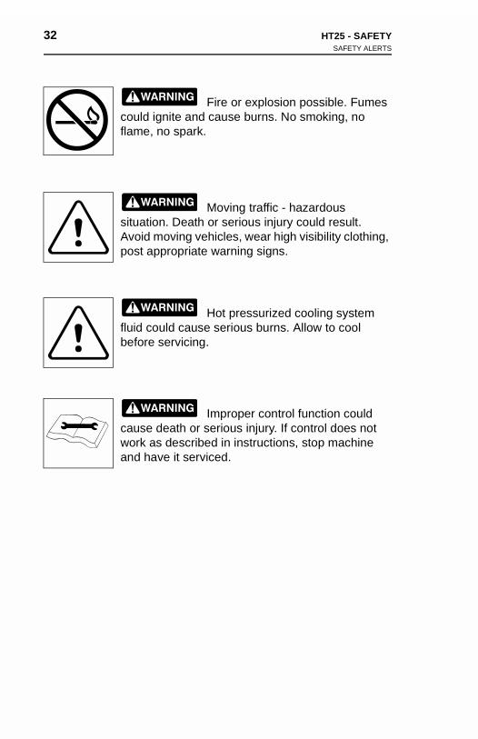
Fire or explosion possible. Fumes could ignite and cause burns. No smoking, no flame, no spark.
Moving traffic - hazardous situation. Death or serious injury could result. Avoid moving vehicles, wear high visibility clothing, post appropriate warning signs.
Hot pressurized cooling system fluid could cause serious burns. Allow to cool before servicing.
Improper control function could cause death or serious injury. If control does not work as described in instructions, stop machine and have it serviced.
Fire or explosion possible. Fumes could ignite and cause burns. No smoking, no flame, no spark.
Moving traffic - hazardous situation. Death or serious injury could result. Avoid moving vehicles, wear high visibility clothing, post appropriate warning signs.
Hot pressurized cooling system fluid could cause serious burns. Allow to cool before servicing.
Improper control function could cause death or serious injury. If control does not
work as described in instructions, stop machine and have it serviced.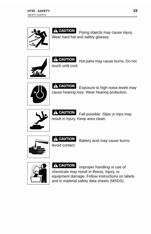
HT25 - SAFETY 33SAFETY ALERTS
Flying objects may cause injury. Wear hard hat and safety glasses.
Hot parts may cause burns. Do not touch until cool.
Exposure to high noise levels may cause hearing loss. Wear hearing protection.
Fall possible. Slips or trips may result in injury. Keep area clean.
Battery acid may cause burns. Avoid contact.
Improper handling or use of chemicals may result in illness, injury, or equipment damage. Follow instructions on labels and in material safety data sheets (MSDS).

34 HT25 - SAFETYSAFETY ALERTS
34 HT25 - SAFETYSAFETY ALERTS
HT25 - TRACTOR 35DAILY INSPECTION
TRACTOR
DAILY INSPECTION
For efficient use of your machine, do the following before each day's work.
• Check general appearance of tractor and attachments. Look for loose, worn, or damaged parts and fluid leaks.
• Check condition of all wear items such as fan belts, etc. Check condition of attachment wear items.
• Check fuel level.
• Check that all signs, guards, and shields are in place and readable.
Service machine according to schedules in LUBRICATION and MAINTENANCE and in engine manufacturer's guide.
Incorrect procedures could result in death, injury, or property damage. Learn to use equipment correctly.
NOTICES:
• Read operator's manual before operating equipment. Follow instructions carefully. Contact your Ditch Witch dealer for operation information or demonstration.
• Wear hard hat, safety glasses, and other protective gear required by job. Do not wear jewelry or loose clothing that can catch on controls.
sf1027
36 HT25 - TRACTORSTARTUP
36 HT25 - TRACTORSTARTUP
STARTUP
Before operating tractor, read engine manufacturer’s starting and operating instructions. Follow instructions for new engine break-in.
1. Fasten seatbelt.
2. Check that track controls and digging chain control are in neutral position.
3. Move hand throttle to 1/2 open.
Runaway possible. Machine could run over you or others. Learn how to use all controls. Start and operate only from operator’s position.
4. If starting in cold weather, press glow plug button for appropriate length of time. See CONTROLS for more information.
sf1008
STA
Beforeoperatin.
1. Fa
2. Chne
3. Mo
4. If sapinf
sf1008
RTUP
operating tractor, read engine manufacturer’s starting and ing instructions. Follow instructions for new engine break-
sten seatbelt.
eck that track controls and digging chain control are in utral position.
ve hand throttle to 1/2 open.
Runaway possible. Machine could run over you or others. Learn how to use all controls. Start and operate only from operator’s position.
tarting in cold weather, press glow plug button for propriate length of time. See CONTROLS for more ormation.
HT25 - TRACTOR 37STARTUP
5. Turn key. Indicators will light.
If engine does not turn, check start interlock display. See CONTROLS. If engine turns but does not start within 10 seconds, allow starter to cool before trying to start again.
6. After engine is started, run engine at half-throttle or less for five minutes before operating tractor.
During warm up, check that all controls work properly.
Improper control function could cause death or serious injury. If control does not work as described in instructions, stop machine and have it serviced.
sf1020
38 HT25 - TRACTOROPERATION
38 HT25 - TRACTOROPERATION
OPERATION
1. Raise backfill blade and digging boom.
2. Adjust throttle.
3. Move track controls to forward or reverse.
Moving traffic – hazardous situation. Death or serious injury could result. Avoid moving vehicles, wear high visibility clothing, post appropriate warning signs.
SHUTDOWN
1. When job is complete, move track controls to neutral.
2. Lower attachments to ground or stowed position.
3. Move throttle to idle and let machine idle for 3 minutes to cool engine.
4. Turn key to stop position. If leaving machine unattended, remove key.
5. For maintenance or long-term storage, turn optional battery disconnect switch to disconnect position.
sf1001
OPE
1. Ra
2. Ad
3. Mo
SHU
1. W
2. Lo
3. Moen
4. Turem
5. Fodis
sf1001
RATION
ise backfill blade and digging boom.
just throttle.
ve track controls to forward or reverse.
Moving traffic – hazardous situation. Death or serious injury could result. Avoid moving vehicles, wear high visibility clothing, post appropriate warning signs.
TDOWN
hen job is complete, move track controls to neutral.
wer attachments to ground or stowed position.
ve throttle to idle and let machine idle for 3 minutes to cool gine.
rn key to stop position. If leaving machine unattended, ove key.
r maintenance or long-term storage, turn optional battery connect switch to disconnect position.
HT25 - TRANSPORTATION 39LIFT
TRANSPORTATION
LIFT
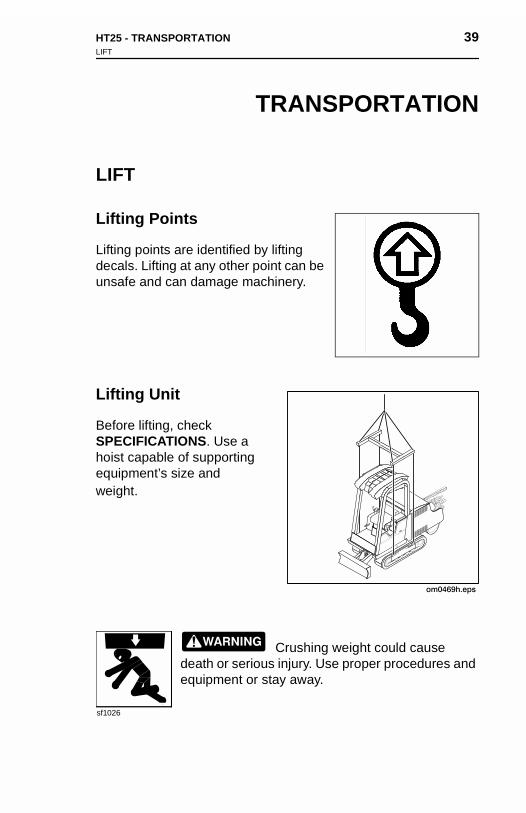
Lifting Points
Lifting points are identified by lifting decals. Lifting at any other point can be unsafe and can damage machinery.
Lifting Unit
Before lifting, check SPECIFICATIONS. Use a hoist capable of supporting equipment’s size and weight.
Crushing weight could cause death or serious injury. Use proper procedures and equipment or stay away.
sf1026
HT25 - TRANSPORTATION 39LIFT
TRANSPORTATION
LIFT
Lifting Points
Lifting points are identified by lifting decals. Lifting at any other point can be unsafe and can damage machinery.
Lifting Unit
Before lifting, check
SPECIFICATIONS. Use a hoist capable of supporting equipment’s size and weight.Crushing weight could cause death or serious injury. Use proper procedures and equipment or stay away.
sf1026
40 HT25 - TRANSPORTATIONTIEDOWN
40 HT25 - TRANSPORTATIONTIEDOWN
TIEDOWN
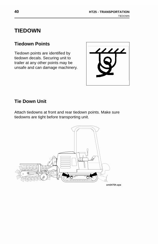
Tiedown Points
Tiedown points are identified by tiedown decals. Securing unit to trailer at any other points may be unsafe and can damage machinery.
Tie Down Unit
Attach tiedowns at front and rear tiedown points. Make sure tiedowns are tight before transporting unit.
TIED
Tiedo
Tiedowtiedowtrailer unsafe
Tie D
Attachtiedow
OWN
wn Points
n points are identified by n decals. Securing unit to at any other points may be and can damage machinery.
own Unit
tiedowns at front and rear tiedown points. Make sure ns are tight before transporting unit.
HT25 - TRANSPORTATION 41HAUL
HAUL
Crushing weight could cause death or serious injury. Use proper procedures and equipment or stay away.
NOTICES:
• Read trailer operator’s manual before loading or transporting your machine. Incorrectly loaded machine can slip or cause trailer sway.
• Park, load, and unload trailer on a level part of jobsite. Check that unit and trailer do not exceed size or weight regulations.
Rollover possible. If machine rolls over, you could be thrown from seat and killed or crushed. Wear seat belt.
sf1014
sf1011
HT25 - TRANSPORTATION 41HAUL
HAUL
Crushing weight could cause death or serious injury. Use proper procedures and equipment or stay away.
NOTICES:
• Read trailer operator’s manual before loading or transporting your machine. Incorrectly loaded machine can slip or cause trailer sway.
• Park, load, and unload trailer on a level part of jobsite. Check that unit and trailer do not exceed size or weight regulations.
Rollover possible. If machine rolls over, you could be thrown from seat and killed or
sf1014
crushed. Wear seat belt.
sf1011
42 HT25 - TRANSPORTATIONHAUL
42 HT25 - TRANSPORTATIONHAUL
Loading1. Fasten seatbelt and start engine. See TRACTOR for startup
procedures.
2. Raise backfill blade and digging boom, but keep them low.
NOTICE: Stability is reduced if digging boom is offset.
3. Slowly drive tractor onto trailer until tiedown position is reached.
4. Lower backfill blade and digging boom to trailer bed and turn off engine.
5. Securely chain tractor and digging boom to trailer using tiedowns.
NOTICE: Check that unit and trailer do not exceed size or weight regulations.
Load1. Fa
pro
2. Ra
NO
3. Slorea
4. Looff
5. Setie
NOwe
ingsten seatbelt and start engine. See TRACTOR for startup cedures.
ise backfill blade and digging boom, but keep them low.
TICE: Stability is reduced if digging boom is offset.
wly drive tractor onto trailer until tiedown position is ched.
wer backfill blade and digging boom to trailer bed and turn engine.
curely chain tractor and digging boom to trailer using downs.
TICE: Check that unit and trailer do not exceed size or ight regulations.
HT25 - TRANSPORTATION 43HAUL
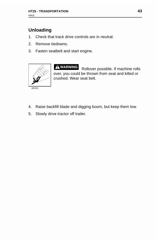
Unloading1. Check that track drive controls are in neutral.
2. Remove tiedowns.
3. Fasten seatbelt and start engine.
Rollover possible. If machine rolls over, you could be thrown from seat and killed or crushed. Wear seat belt.
4. Raise backfill blade and digging boom, but keep them low.
5. Slowly drive tractor off trailer.
sf1011
HT25 - TRANSPORTATION 43HAUL
Unloading1. Check that track drive controls are in neutral.
2. Remove tiedowns.
3. Fasten seatbelt and start engine.
Rollover possible. If machine rolls over, you could be thrown from seat and killed or crushed. Wear seat belt.
4. Raise backfill blade and digging boom, but keep them low.
5. Slowly drive tractor off trailer.
sf1011
44 HT25 - TRANSPORTATIONTOW
44 HT25 - TRANSPORTATIONTOW
TOW
Incorrect procedures could result in death, injury, or property damage. Learn to use equipment correctly.
Under normal conditions, unit should not be towed. If unit becomes disabled and towing is necessary:
• tow for short distances at less than 1 mph (1.6 km/h),
• do not tow for more than 200 yd (183 m),
• steering will be through tow vehicle only.
1. Attach tow line to tiedown points nearest the towing vehicle.
2. Fasten seat belt and begin towing.
IMPORTANT: Tracks will not move.
3. Use tow vehicle or other lifting device to load unit onto trailer.
sf1027
TOW
Underbecom
• tow
• do
• ste
1. At
2. Fa
IM
3. Us
sf1027
Incorrect procedures could result in death, injury, or property damage. Learn to use equipment correctly.
normal conditions, unit should not be towed. If unit es disabled and towing is necessary:
for short distances at less than 1 mph (1.6 km/h),
not tow for more than 200 yd (183 m),
ering will be through tow vehicle only.
tach tow line to tiedown points nearest the towing vehicle.
sten seat belt and begin towing.
PORTANT: Tracks will not move.
e tow vehicle or other lifting device to load unit onto trailer.
HT25 - TRENCHING 45CONTROL OVERVIEW
TRENCHING
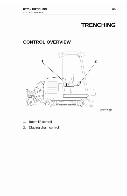
CONTROL OVERVIEW
1. Boom lift control
2. Digging chain control
HT25 - TRENCHING 45CONTROL OVERVIEW
TRENCHING
CONTROL OVERVIEW
1. Boom lift control
2. Digging chain control
46 HT25 - TRENCHINGCONTROL DESCRIPTIONS
46 HT25 - TRENCHINGCONTROL DESCRIPTIONS
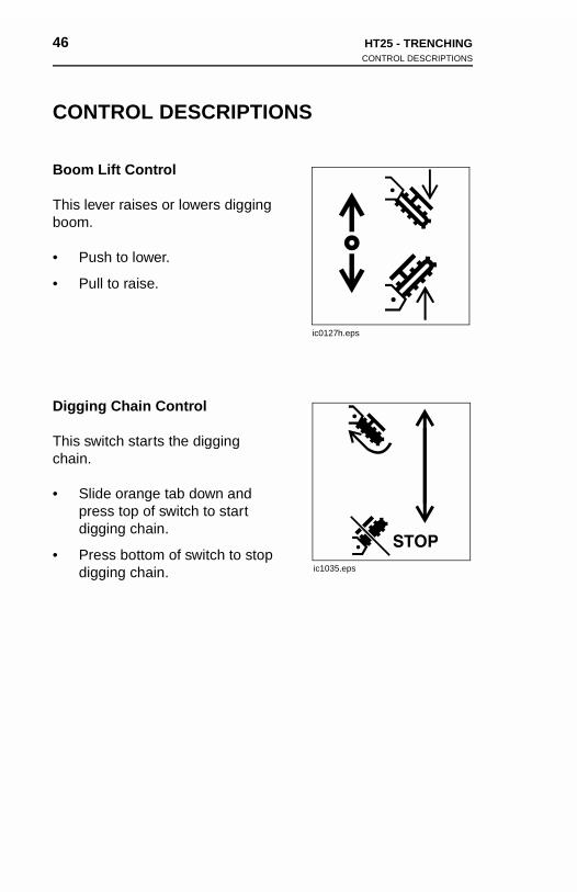
CONTROL DESCRIPTIONS
Boom Lift Control
This lever raises or lowers digging boom.
• Push to lower.
• Pull to raise.
Digging Chain Control
This switch starts the digging chain.
• Slide orange tab down and press top of switch to start digging chain.
• Press bottom of switch to stop digging chain.
ic0127h.eps
ic1035.eps
CON
Boom
This leboom.
• Pu
• Pu
Diggin
This swchain.
• Slipredig
• Prdig
TROL DESCRIPTIONS
Lift Control
ver raises or lowers digging
sh to lower.
ll to raise.
g Chain Control
itch starts the digging
de orange tab down and ss top of switch to start ging chain.
ic0127h.eps
ess bottom of switch to stop ging chain. ic1035.eps
HT25 - TRENCHING 47SETUP
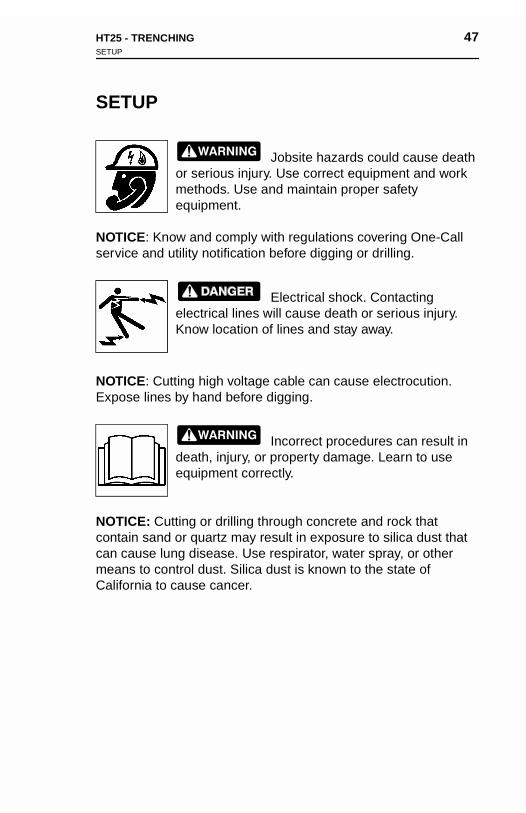
SETUP
Jobsite hazards could cause death or serious injury. Use correct equipment and work methods. Use and maintain proper safety equipment.
NOTICE: Know and comply with regulations covering One-Call service and utility notification before digging or drilling.
Electrical shock. Contacting electrical lines will cause death or serious injury. Know location of lines and stay away.
NOTICE: Cutting high voltage cable can cause electrocution. Expose lines by hand before digging.
Incorrect procedures can result in death, injury, or property damage. Learn to use equipment correctly.
NOTICE: Cutting or drilling through concrete and rock that contain sand or quartz may result in exposure to silica dust that can cause lung disease. Use respirator, water spray, or other means to control dust. Silica dust is known to the state of California to cause cancer.
HT25 - TRENCHING 47SETUP
SETUP
Jobsite hazards could cause death or serious injury. Use correct equipment and work methods. Use and maintain proper safety equipment.
NOTICE: Know and comply with regulations covering One-Call service and utility notification before digging or drilling.
Electrical shock. Contacting electrical lines will cause death or serious injury. Know location of lines and stay away.
NOTICE: Cutting high voltage cable can cause electrocution. Expose lines by hand before digging.
Incorrect procedures can result in
death, injury, or property damage. Learn to use equipment correctly.NOTICE: Cutting or drilling through concrete and rock that contain sand or quartz may result in exposure to silica dust that can cause lung disease. Use respirator, water spray, or other means to control dust. Silica dust is known to the state of California to cause cancer.
48 HT25 - TRENCHINGSETUP
48 HT25 - TRENCHINGSETUP
1. Fasten and adjust seat belt.
2. Start tractor and adjust throttle.
3. Raise boom and backfill blade.
4. Adjust throttle and drive to starting point. Move in line with planned trench.
5. Lower backfill blade.
6. Lower boom to just above the ground.
7. Check that digging chain control and track controls are in neutral.
8. Check that boom is in line with planned trench.
1. Fa
2. St
3. Ra
4. Adpla
5. Lo
6. Lo
7. Chne
8. Ch
sten and adjust seat belt.
art tractor and adjust throttle.
ise boom and backfill blade.
just throttle and drive to starting point. Move in line with nned trench.
wer backfill blade.
wer boom to just above the ground.
eck that digging chain control and track controls are in utral.
eck that boom is in line with planned trench.
HT25 - TRENCHING 49OPERATION
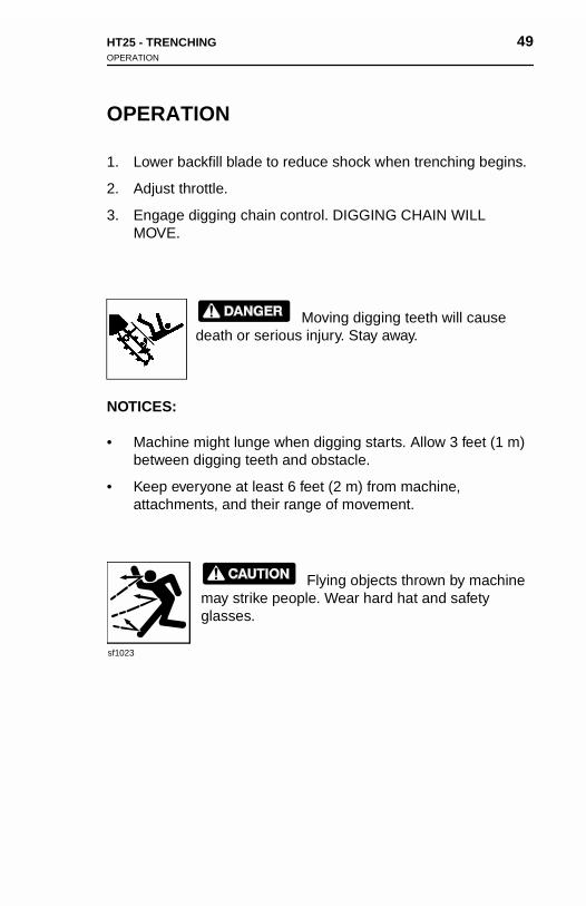
OPERATION
1. Lower backfill blade to reduce shock when trenching begins.
2. Adjust throttle.
3. Engage digging chain control. DIGGING CHAIN WILL MOVE.
Moving digging teeth will cause death or serious injury. Stay away.
NOTICES:
• Machine might lunge when digging starts. Allow 3 feet (1 m) between digging teeth and obstacle.
• Keep everyone at least 6 feet (2 m) from machine, attachments, and their range of movement.
Flying objects thrown by machine may strike people. Wear hard hat and safety glasses.
sf1023
HT25 - TRENCHING 49OPERATION
OPERATION
1. Lower backfill blade to reduce shock when trenching begins.
2. Adjust throttle.
3. Engage digging chain control. DIGGING CHAIN WILL MOVE.
Moving digging teeth will cause death or serious injury. Stay away.
NOTICES:
• Machine might lunge when digging starts. Allow 3 feet (1 m) between digging teeth and obstacle.
• Keep everyone at least 6 feet (2 m) from machine,
attachments, and their range of movement.Flying objects thrown by machine may strike people. Wear hard hat and safety glasses.
sf1023
50 HT25 - TRENCHINGOPERATION
50 HT25 - TRENCHINGOPERATION
4. Increase engine speed to full throttle.
5. Slowly lower digging boom to desired trench depth.
6. Raise backfill blade.
7. Push track controls forward to trenching speed.
8. When trench is complete, move track controls to neutral.
9. Move throttle to half open.
10. Raise boom. As boom clears top of trench, move digging chain control to neutral.
11. Drive forward, lower backfill blade and boom.
12. Move throttle to idle and let machine idle for three minutes to cool engine.
13. Turn ignition switch to stop position.
4. Inc
5. Slo
6. Ra
7. Pu
8. W
9. Mo
10. Rach
11. Dr
12. Moco
13. Tu
rease engine speed to full throttle.
wly lower digging boom to desired trench depth.
ise backfill blade.
sh track controls forward to trenching speed.
hen trench is complete, move track controls to neutral.
ve throttle to half open.
ise boom. As boom clears top of trench, move digging ain control to neutral.
ive forward, lower backfill blade and boom.
ve throttle to idle and let machine idle for three minutes to ol engine.
rn ignition switch to stop position.
HT25 - TRENCHING 51OPERATING TIPS
OPERATING TIPS
• Avoid using badly worn teeth. When replacing teeth, maintain original pattern. Use Ditch Witch replacement teeth.
• Operate engine at full throttle.
• Do not make sharp turns. Lower boom to full depth when turning.
• While trenching, steering is best accomplished by feathering one track control at a time, rather than both together.
• If an object becomes lodged in chain, move digging chain clutch to neutral and raise boom slightly. If object must be removed manually, turn engine off.
• Before operating with rock chains, check bits for free rotation. Tap bits lightly with a hammer and turn by hand. If bits are stuck, remove and clean packed soil from bit block.
• Carbide bits are recommended for cutting abrasive material, such as sandstone or frozen sands or gravels.
OPTIONAL EQUIPMENT
Chain
A variety of chains, teeth, and tooth patterns are available to provide efficient digging at any jobsite. For more information, contact your Ditch Witch dealer.
Trench Cleaner
Trench cleaners remove spoils from the trench floor. For more information about the mechanical trench cleaner available for use on the HT25, contact your Ditch Witch dealer.

52 HT25 - TRENCHING 52 HT25 - TRENCHING
HT25 - BACKHOE 53CONTROL OVERVIEW
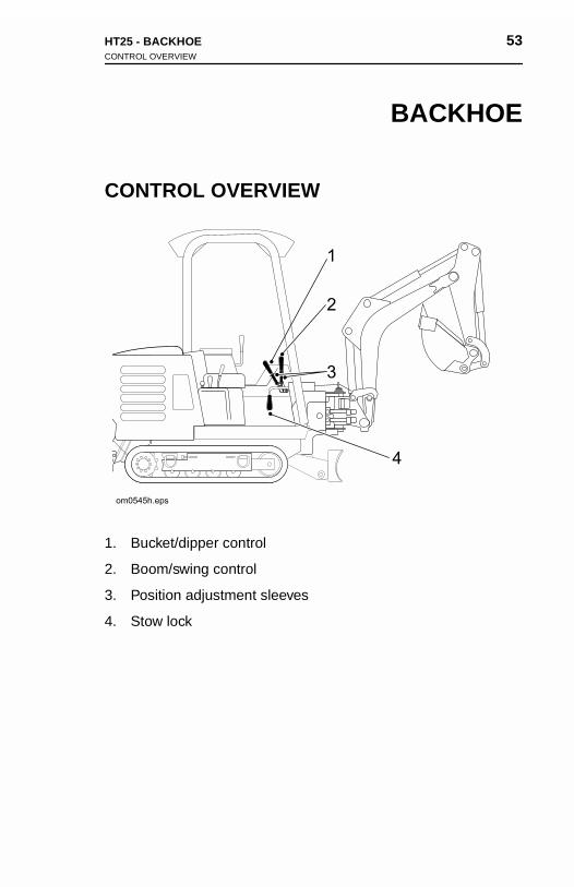
BACKHOE
CONTROL OVERVIEW
1. Bucket/dipper control
2. Boom/swing control
3. Position adjustment sleeves
4. Stow lock
HT25 - BACKHOE 53CONTROL OVERVIEW
BACKHOE
CONTROL OVERVIEW
1. Bucket/dipper control
2. Boom/swing control
3. Position adjustment sleeves
4. Stow lock
54 HT25 - BACKHOECONTROL DESCRIPTIONS
54 HT25 - BACKHOECONTROL DESCRIPTIONS
CONTROL DESCRIPTIONS
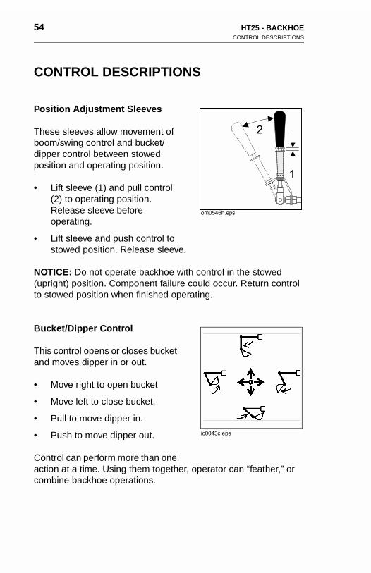
Position Adjustment Sleeves
These sleeves allow movement of boom/swing control and bucket/dipper control between stowed position and operating position.
• Lift sleeve (1) and pull control (2) to operating position. Release sleeve before operating.
• Lift sleeve and push control to stowed position. Release sleeve.
NOTICE: Do not operate backhoe with control in the stowed (upright) position. Component failure could occur. Return control to stowed position when finished operating.
Bucket/Dipper Control
This control opens or closes bucket and moves dipper in or out.
• Move right to open bucket
• Move left to close bucket.
• Pull to move dipper in.
• Push to move dipper out.
Control can perform more than one action at a time. Using them together, operator can “feather,” or combine backhoe operations.
ic0043c.eps
CON
Positio
Theseboom/dipperpositio
• Lif(2)Reop
• Lifsto
NOTIC(uprighto stow
Bucke
This coand m
• Mo
• Mo
• Pu
• Pu
Controaction combin
TROL DESCRIPTIONS
n Adjustment Sleeves
sleeves allow movement of swing control and bucket/ control between stowed n and operating position.
t sleeve (1) and pull control to operating position. lease sleeve before erating.
t sleeve and push control to wed position. Release sleeve.
E: Do not operate backhoe with control in the stowed t) position. Component failure could occur. Return control ed position when finished operating.
t/Dipper Control
ntrol opens or closes bucket oves dipper in or out.
ve right to open bucket
ve left to close bucket.
ll to move dipper in.
sh to move dipper out.
l can perform more than one at a time. Using them together, operator can “feather,” or e backhoe operations.
ic0043c.eps
HT25 - BACKHOE 55CONTROL DESCRIPTIONS
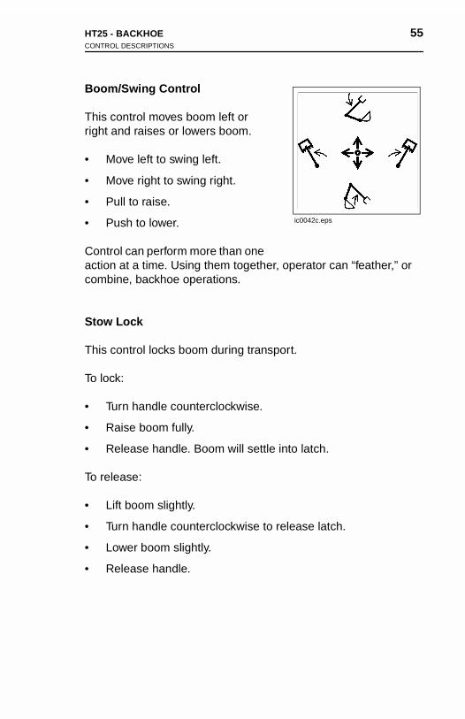
Boom/Swing Control
This control moves boom left or right and raises or lowers boom.
• Move left to swing left.
• Move right to swing right.
• Pull to raise.
• Push to lower.
Control can perform more than one action at a time. Using them together, operator can “feather,” or combine, backhoe operations.
Stow Lock
This control locks boom during transport.
To lock:
• Turn handle counterclockwise.
• Raise boom fully.
• Release handle. Boom will settle into latch.
To release:
• Lift boom slightly.
• Turn handle counterclockwise to release latch.
• Lower boom slightly.
• Release handle.
ic0042c.eps
HT25 - BACKHOE 55CONTROL DESCRIPTIONS
Boom/Swing Control
This control moves boom left or right and raises or lowers boom.
• Move left to swing left.
• Move right to swing right.
• Pull to raise.
• Push to lower.
Control can perform more than one action at a time. Using them together, operator can “feather,” or combine, backhoe operations.
Stow Lock
This control locks boom during transport.
To lock:
ic0042c.eps
• Turn handle counterclockwise.
• Raise boom fully.
• Release handle. Boom will settle into latch.
To release:
• Lift boom slightly.
• Turn handle counterclockwise to release latch.
• Lower boom slightly.
• Release handle.

56 HT25 - BACKHOESETUP
56 HT25 - BACKHOESETUP
SETUP
1. Move track controls to neutral position.
2. Lower rear attachment to 6 in (152 mm) above ground.
3. Check that backfill blade is straight and lower it to ground.
4. Adjust throttle.
NOTICE: Engine speed affects speed of backhoe operation.
5. Raise boom to release tension on stow lock.
6. Release stow lock.
SET
1. Mo
2. Lo
3. Ch
4. Ad
NO
5. Ra
6. Re
UP
ve track controls to neutral position.
wer rear attachment to 6 in (152 mm) above ground.
eck that backfill blade is straight and lower it to ground.
just throttle.
TICE: Engine speed affects speed of backhoe operation.
ise boom to release tension on stow lock.
lease stow lock.
HT25 - BACKHOE 57OPERATION
OPERATION
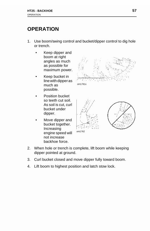
1. Use boom/swing control and bucket/dipper control to dig hole or trench.
• Keep dipper and boom at right angles as much as possible for maximum power.
• Keep bucket in line with dipper as much as possible.
• Position bucket so teeth cut soil. As soil is cut, curl bucket under dipper.
• Move dipper and bucket together. Increasing engine speed will not increase backhoe force.
2. When hole or trench is complete, lift boom while keeping dipper pointed at ground.
3. Curl bucket closed and move dipper fully toward boom.
4. Lift boom to highest position and latch stow lock.
om1761x
om1762
HT25 - BACKHOE 57OPERATION
OPERATION
1. Use boom/swing control and bucket/dipper control to dig hole or trench.
• Keep dipper and boom at right angles as much as possible for maximum power.
• Keep bucket in line with dipper as much as possible.
• Position bucket so teeth cut soil. As soil is cut, curl bucket under dipper.
• Move dipper and bucket together.
om1761x
Increasing engine speed will not increase backhoe force.
2. When hole or trench is complete, lift boom while keeping dipper pointed at ground.
3. Curl bucket closed and move dipper fully toward boom.
4. Lift boom to highest position and latch stow lock.
om1762

58 HT25 - BACKHOE 58 HT25 - BACKHOE
HT25 - LUBRICATION 59
LUBRICATION
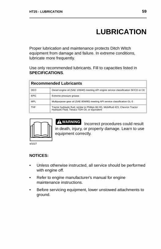
Proper lubrication and maintenance protects Ditch Witch equipment from damage and failure. In extreme conditions, lubricate more frequently.
Use only recommended lubricants. Fill to capacities listed in SPECIFICATIONS.
Incorrect procedures could result in death, injury, or property damage. Learn to use equipment correctly.
NOTICES:
• Unless otherwise instructed, all service should be performed with engine off.
• Refer to engine manufacturer’s manual for engine maintenance instructions.
• Before servicing equipment, lower unstowed attachments to ground.
Recommended Lubricants
DEO Diesel engine oil (SAE 10W40) meeting API engine service classification SF/CD or CE
EPG Extreme pressure grease
MPL Multipurpose gear oil (SAE 80W90) meeting API service classification GL-5
THF Tractor hydraulic fluid, similar to Phillips 66 HG, Mobilfluid 423, Chevron Tractor Hydraulic Fluid, Texaco TDH Oil, or equivalent
sf1027
HT25 - LUBRICATION 59
LUBRICATION
Proper lubrication and maintenance protects Ditch Witch equipment from damage and failure. In extreme conditions, lubricate more frequently.
Use only recommended lubricants. Fill to capacities listed in SPECIFICATIONS.
Incorrect procedures could result in death, injury, or property damage. Learn to use equipment correctly.
Recommended Lubricants
DEO Diesel engine oil (SAE 10W40) meeting API engine service classification SF/CD or CE
EPG Extreme pressure grease
MPL Multipurpose gear oil (SAE 80W90) meeting API service classification GL-5
THF Tractor hydraulic fluid, similar to Phillips 66 HG, Mobilfluid 423, Chevron Tractor Hydraulic Fluid, Texaco TDH Oil, or equivalent
NOTICES:
• Unless otherwise instructed, all service should be performed with engine off.
• Refer to engine manufacturer’s manual for engine maintenance instructions.
• Before servicing equipment, lower unstowed attachments to ground.
sf1027
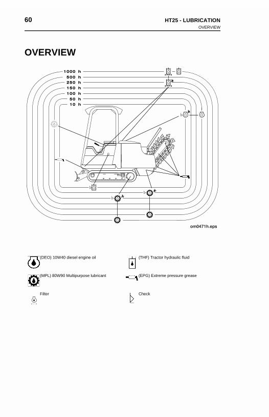
60 HT25 - LUBRICATIONOVERVIEW
60 HT25 - LUBRICATIONOVERVIEW
OVERVIEW
(DEO) 10W40 diesel engine oil (THF) Tractor hydraulic fluid
(MPL) 80W90 Multipurpose lubricant (EPG) Extreme pressure grease
Filter Check
OVE
(D
(M
Fi
RVIEW
EO) 10W40 diesel engine oil (THF) Tractor hydraulic fluid
PL) 80W90 Multipurpose lubricant (EPG) Extreme pressure grease
lter Check
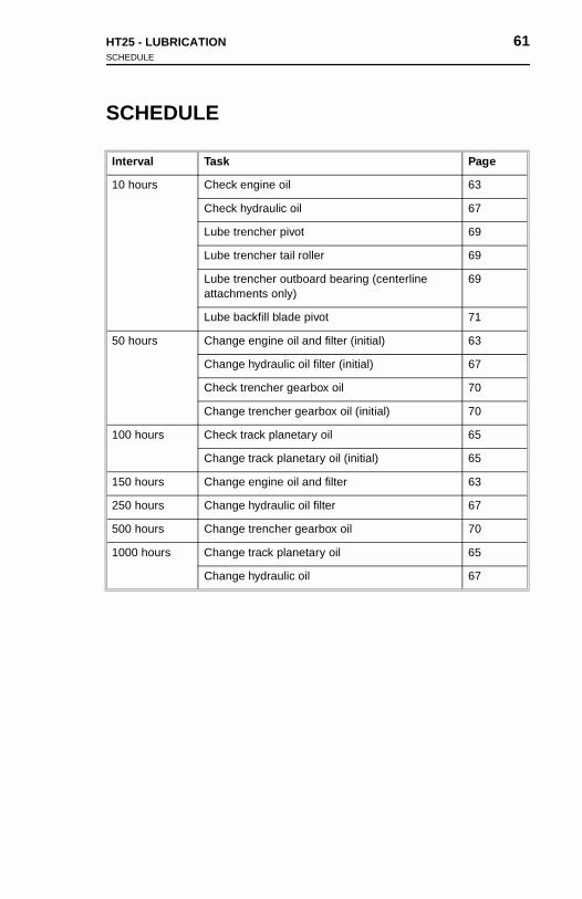
HT25 - LUBRICATION 61SCHEDULE
SCHEDULE
Interval Task Page
10 hours Check engine oil 63
Check hydraulic oil 67
Lube trencher pivot 69
Lube trencher tail roller 69
Lube trencher outboard bearing (centerline attachments only)
69
Lube backfill blade pivot 71
50 hours Change engine oil and filter (initial) 63
Change hydraulic oil filter (initial) 67
Check trencher gearbox oil 70
Change trencher gearbox oil (initial) 70
100 hours Check track planetary oil 65
Change track planetary oil (initial) 65
150 hours Change engine oil and filter 63
250 hours Change hydraulic oil filter 67
500 hours Change trencher gearbox oil 70
1000 hours Change track planetary oil 65
Change hydraulic oil 67
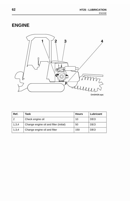
62 HT25 - LUBRICATIONENGINE
62 HT25 - LUBRICATIONENGINE
ENGINE
Ref. Task Hours Lubricant
2 Check engine oil 10 DEO
1,3,4 Change engine oil and filter (initial) 50 DEO
1,3,4 Change engine oil and filter 150 DEO
ENG
Ref.
2
1,3,4
1,3,4
INE
Task Hours Lubricant
Check engine oil 10 DEO
Change engine oil and filter (initial) 50 DEO
Change engine oil and filter 150 DEO
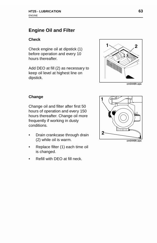
HT25 - LUBRICATION 63ENGINE
Engine Oil and Filter
Check
Check engine oil at dipstick (1) before operation and every 10 hours thereafter.
Add DEO at fill (2) as necessary to keep oil level at highest line on dipstick.
Change
Change oil and filter after first 50 hours of operation and every 150 hours thereafter. Change oil more frequently if working in dusty conditions.
• Drain crankcase through drain (2) while oil is warm.
• Replace filter (1) each time oil is changed.
• Refill with DEO at fill neck.
om0448h.eps
1 2
HT25 - LUBRICATION 63ENGINE
Engine Oil and Filter
Check
Check engine oil at dipstick (1) before operation and every 10 hours thereafter.
Add DEO at fill (2) as necessary to keep oil level at highest line on dipstick.
Change
Change oil and filter after first 50 hours of operation and every 150 hours thereafter. Change oil more frequently if working in dusty conditions.
om0448h.eps
1 2
• Drain crankcase through drain (2) while oil is warm.
• Replace filter (1) each time oil is changed.
• Refill with DEO at fill neck.
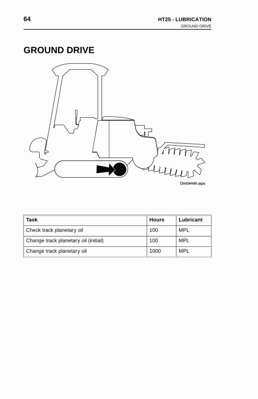
64 HT25 - LUBRICATIONGROUND DRIVE
64 HT25 - LUBRICATIONGROUND DRIVE
GROUND DRIVE
Task Hours Lubricant
Check track planetary oil 100 MPL
Change track planetary oil (initial) 100 MPL
Change track planetary oil 1000 MPL
GRO
Task
Check
Chang
Chang
UND DRIVE
Hours Lubricant
track planetary oil 100 MPL
e track planetary oil (initial) 100 MPL
e track planetary oil 1000 MPL
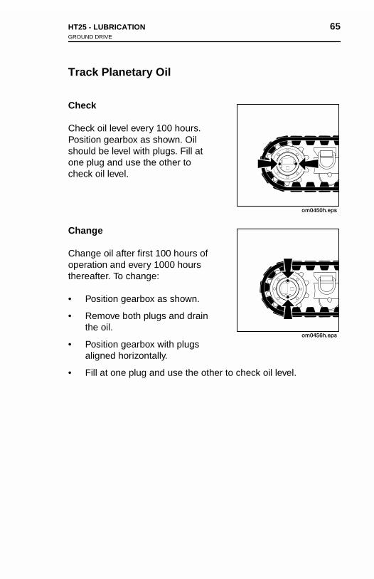
HT25 - LUBRICATION 65GROUND DRIVE
Track Planetary Oil
Check
Check oil level every 100 hours. Position gearbox as shown. Oil should be level with plugs. Fill at one plug and use the other to check oil level.
Change
Change oil after first 100 hours of operation and every 1000 hours thereafter. To change:
• Position gearbox as shown.
• Remove both plugs and drain the oil.
• Position gearbox with plugs aligned horizontally.
• Fill at one plug and use the other to check oil level.
om0450h.eps
om0456h.eps
HT25 - LUBRICATION 65GROUND DRIVE
Track Planetary Oil
Check
Check oil level every 100 hours. Position gearbox as shown. Oil should be level with plugs. Fill at one plug and use the other to check oil level.
Change
Change oil after first 100 hours of operation and every 1000 hours thereafter. To change:
• Position gearbox as shown.
om0450h.eps
• Remove both plugs and drain the oil.
• Position gearbox with plugs aligned horizontally.
• Fill at one plug and use the other to check oil level.
om0456h.eps
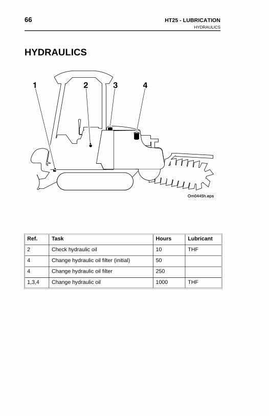
66 HT25 - LUBRICATIONHYDRAULICS
66 HT25 - LUBRICATIONHYDRAULICS
HYDRAULICS
Ref. Task Hours Lubricant
2 Check hydraulic oil 10 THF
4 Change hydraulic oil filter (initial) 50
4 Change hydraulic oil filter 250
1,3,4 Change hydraulic oil 1000 THF
HYD
Ref.
2
4
4
1,3,4
RAULICS
Task Hours Lubricant
Check hydraulic oil 10 THF
Change hydraulic oil filter (initial) 50
Change hydraulic oil filter 250
Change hydraulic oil 1000 THF

HT25 - LUBRICATION 67HYDRAULICS
Hydraulic Oil
Check
With frame level and digging boom fully raised, check oil at sight glass (2) every 10 hours.
Add THF at fill (3) as necessary. Clean dust from cap by blowing with low-pressure air.
Change
Change oil filter at 50 hours and every 250 hours thereafter.
Drain hydraulic oil (1), change filter (4), and refill with THF every 1000 hours. Change oil and filter every 500 hours if jobsite temperature exceeds 100°F (38°C) more than 50% of the time.
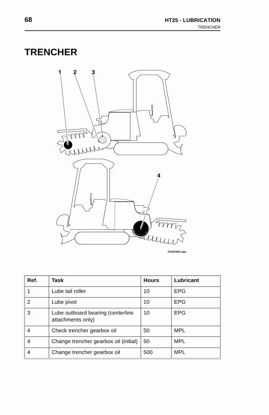
68 HT25 - LUBRICATIONTRENCHER
68 HT25 - LUBRICATIONTRENCHER
TRENCHER
Ref. Task Hours Lubricant
1 Lube tail roller 10 EPG
2 Lube pivot 10 EPG
3 Lube outboard bearing (centerline attachments only)
10 EPG
4 Check trencher gearbox oil 50 MPL
4 Change trencher gearbox oil (initial) 50 MPL
4 Change trencher gearbox oil 500 MPL
TRE
Ref.
1
2
3
4
4
4
NCHER
Task Hours Lubricant
Lube tail roller 10 EPG
Lube pivot 10 EPG
Lube outboard bearing (centerline attachments only)
10 EPG
Check trencher gearbox oil 50 MPL
Change trencher gearbox oil (initial) 50 MPL
Change trencher gearbox oil 500 MPL
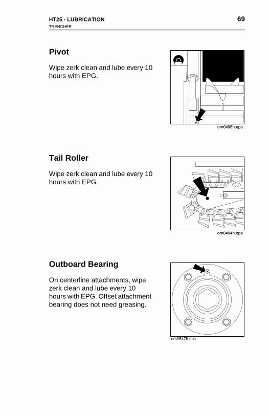
HT25 - LUBRICATION 69TRENCHER
Pivot
Wipe zerk clean and lube every 10 hours with EPG.
Tail Roller
Wipe zerk clean and lube every 10 hours with EPG.
Outboard Bearing
On centerline attachments, wipe zerk clean and lube every 10 hours with EPG. Offset attachment bearing does not need greasing.
HT25 - LUBRICATION 69TRENCHER
Pivot
Wipe zerk clean and lube every 10 hours with EPG.
Tail Roller
Wipe zerk clean and lube every 10 hours with EPG.
Outboard Bearing
On centerline attachments, wipe zerk clean and lube every 10 hours with EPG. Offset attachment bearing does not need greasing.

70 HT25 - LUBRICATIONTRENCHER
70 HT25 - LUBRICATIONTRENCHER
Gearbox
Check
Check oil at fill plug (1) every 50 hours. Keep oil level at plug. If necessary, add MPL at fill plug.
Change
Change oil after 50 hours and every 500 hours thereafter. Drain at drain plug (2). Replace drain plug and add MPL at fill plug until oil is level with plug.
Gear
Check
Checkhours.necess
Chang
Changevery 5plug a
box
oil at fill plug (1) every 50 Keep oil level at plug. If ary, add MPL at fill plug.
e
e oil after 50 hours and 00 hours thereafter. Drain at drain plug (2). Replace drain
nd add MPL at fill plug until oil is level with plug.
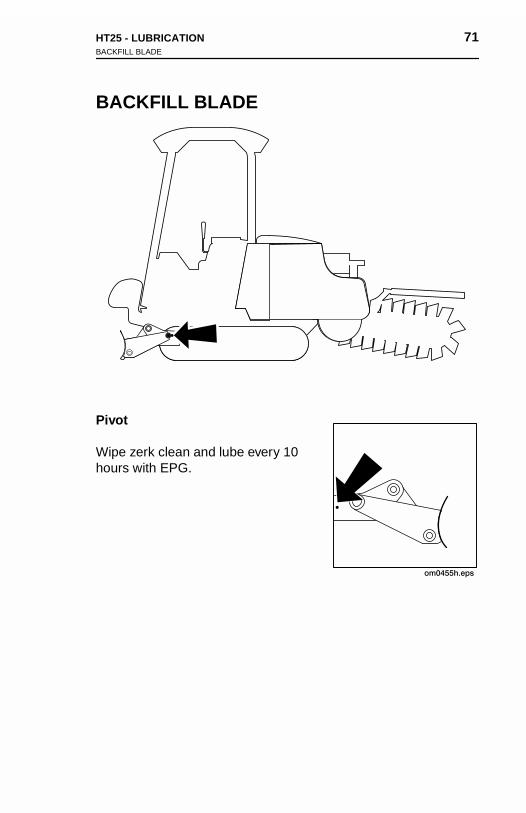
HT25 - LUBRICATION 71BACKFILL BLADE
BACKFILL BLADE
Pivot
Wipe zerk clean and lube every 10 hours with EPG.
HT25 - LUBRICATION 71BACKFILL BLADE
BACKFILL BLADE
Pivot
Wipe zerk clean and lube every 10 hours with EPG.

72 HT25 - LUBRICATION 72 HT25 - LUBRICATION
HT25 - MAINTENANCE 73
MAINTENANCE
Incorrect procedures could result in death, injury, or property damage. Learn to use equipment correctly.
NOTICES:
• Unless otherwise instructed, all service should be performed with engine shut off.
• Refer to engine manufacturer’s manual for engine maintenance instructions.
• Before servicing equipment, lower unstowed attachments to ground.
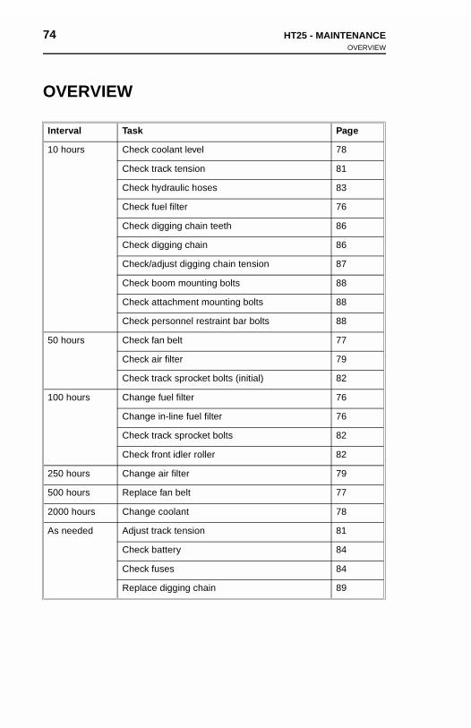
74 HT25 - MAINTENANCEOVERVIEW
74 HT25 - MAINTENANCEOVERVIEW
OVERVIEW
Interval Task Page
10 hours Check coolant level 78
Check track tension 81
Check hydraulic hoses 83
Check fuel filter 76
Check digging chain teeth 86
Check digging chain 86
Check/adjust digging chain tension 87
Check boom mounting bolts 88
Check attachment mounting bolts 88
Check personnel restraint bar bolts 88
50 hours Check fan belt 77
Check air filter 79
Check track sprocket bolts (initial) 82
100 hours Change fuel filter 76
Change in-line fuel filter 76
Check track sprocket bolts 82
Check front idler roller 82
250 hours Change air filter 79
500 hours Replace fan belt 77
2000 hours Change coolant 78
As needed Adjust track tension 81
Check battery 84
Check fuses 84
Replace digging chain 89
OVE
Interva
10 hou
50 hou
100 ho
250 ho
500 ho
2000 h
As nee
RVIEW
l Task Page
rs Check coolant level 78
Check track tension 81
Check hydraulic hoses 83
Check fuel filter 76
Check digging chain teeth 86
Check digging chain 86
Check/adjust digging chain tension 87
Check boom mounting bolts 88
Check attachment mounting bolts 88
Check personnel restraint bar bolts 88
rs Check fan belt 77
Check air filter 79
Check track sprocket bolts (initial) 82
urs Change fuel filter 76
Change in-line fuel filter 76
Check track sprocket bolts 82
Check front idler roller 82
urs Change air filter 79
urs Replace fan belt 77
ours Change coolant 78
ded Adjust track tension 81
Check battery 84
Check fuses 84
Replace digging chain 89
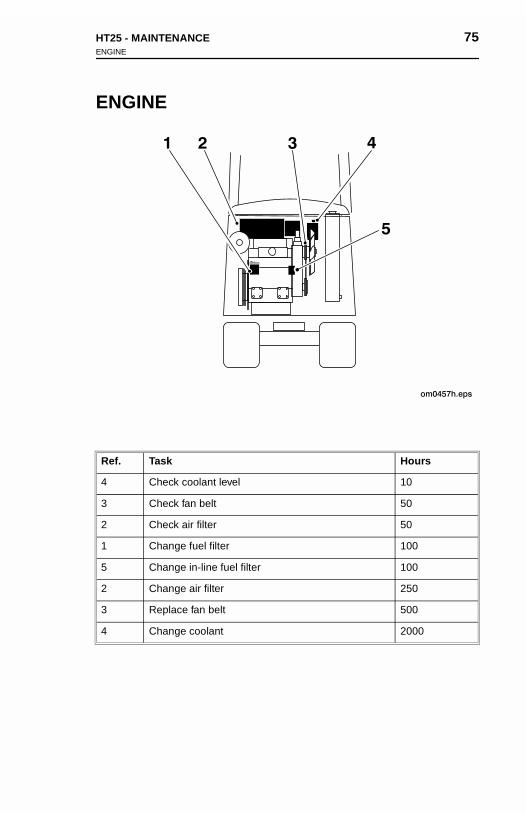
HT25 - MAINTENANCE 75ENGINE
ENGINE
Ref. Task Hours
4 Check coolant level 10
3 Check fan belt 50
2 Check air filter 50
1 Change fuel filter 100
5 Change in-line fuel filter 100
2 Change air filter 250
3 Replace fan belt 500
4 Change coolant 2000
HT25 - MAINTENANCE 75ENGINE
ENGINE
Ref. Task Hours
4 Check coolant level 10
3 Check fan belt 50
2 Check air filter 50
1 Change fuel filter 100
5 Change in-line fuel filter 100
2 Change air filter 250
3 Replace fan belt 500
4 Change coolant 2000
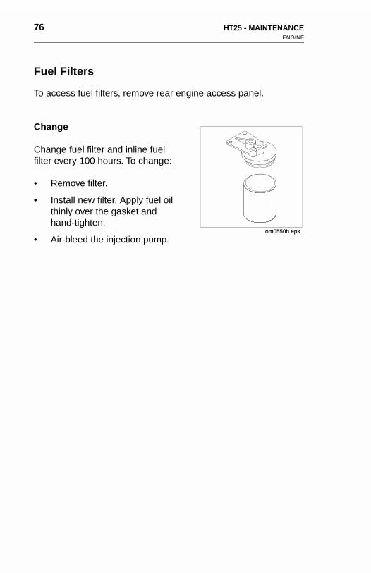
76 HT25 - MAINTENANCEENGINE
76 HT25 - MAINTENANCEENGINE
Fuel Filters
To access fuel filters, remove rear engine access panel.
Change
Change fuel filter and inline fuel filter every 100 hours. To change:
• Remove filter.
• Install new filter. Apply fuel oil thinly over the gasket and hand-tighten.
• Air-bleed the injection pump.
Fuel
To acc
Chang
Changfilter ev
• Re
• Insthiha
• Air
Filters
ess fuel filters, remove rear engine access panel.
e
e fuel filter and inline fuel ery 100 hours. To change:
move filter.
tall new filter. Apply fuel oil nly over the gasket and nd-tighten.
-bleed the injection pump.
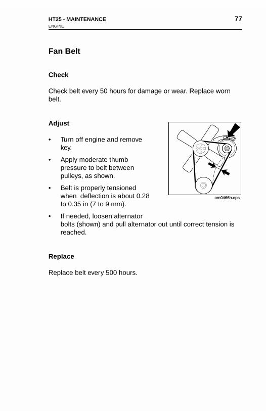
HT25 - MAINTENANCE 77ENGINE
Fan Belt
Check
Check belt every 50 hours for damage or wear. Replace worn belt.
Adjust
• Turn off engine and remove key.
• Apply moderate thumb pressure to belt between pulleys, as shown.
• Belt is properly tensioned when deflection is about 0.28 to 0.35 in (7 to 9 mm).
• If needed, loosen alternator bolts (shown) and pull alternator out until correct tension is reached.
Replace
Replace belt every 500 hours.
om0466h.eps
HT25 - MAINTENANCE 77ENGINE
Fan Belt
Check
Check belt every 50 hours for damage or wear. Replace worn belt.
Adjust
• Turn off engine and remove key.
• Apply moderate thumb pressure to belt between pulleys, as shown.
• Belt is properly tensioned when deflection is about 0.28 to 0.35 in (7 to 9 mm).
• If needed, loosen alternator
om0466h.eps
bolts (shown) and pull alternator out until correct tension is reached.
Replace
Replace belt every 500 hours.
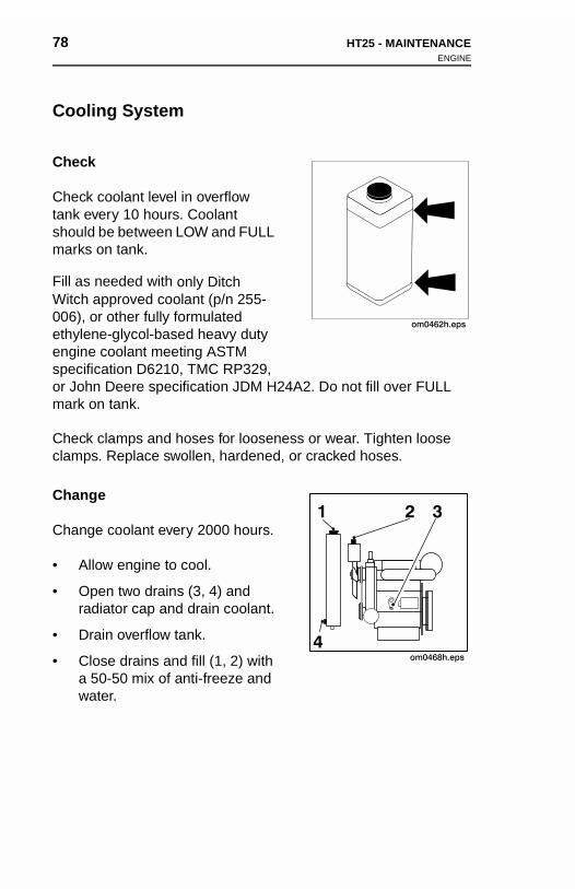
78 HT25 - MAINTENANCEENGINE
78 HT25 - MAINTENANCEENGINE
Cooling System
Check
Check coolant level in overflow tank every 10 hours. Coolant should be between LOW and FULL marks on tank.
Fill as needed with only Ditch Witch approved coolant (p/n 255-006), or other fully formulated ethylene-glycol-based heavy duty engine coolant meeting ASTM specification D6210, TMC RP329, or John Deere specification JDM H24A2. Do not fill over FULL mark on tank.
Check clamps and hoses for looseness or wear. Tighten loose clamps. Replace swollen, hardened, or cracked hoses.
Change
Change coolant every 2000 hours.
• Allow engine to cool.
• Open two drains (3, 4) and radiator cap and drain coolant.
• Drain overflow tank.
• Close drains and fill (1, 2) with a 50-50 mix of anti-freeze and water.
om0462h.eps
Cooli
Check
Checktank evshouldmarks
Fill as Witch 006), oethylenenginespecifior Johmark o
Checkclamps
Chang
Chang
• All
• Oprad
• Dr
• Cla 5wa
ng System
coolant level in overflow ery 10 hours. Coolant be between LOW and FULL on tank.
needed with only Ditch approved coolant (p/n 255-r other fully formulated e-glycol-based heavy duty coolant meeting ASTM cation D6210, TMC RP329, n Deere specification JDM H24A2. Do not fill over FULL n tank.
clamps and hoses for looseness or wear. Tighten loose . Replace swollen, hardened, or cracked hoses.
e
e coolant every 2000 hours.
om0462h.eps
ow engine to cool.
en two drains (3, 4) and iator cap and drain coolant.
ain overflow tank.
ose drains and fill (1, 2) with 0-50 mix of anti-freeze and ter.
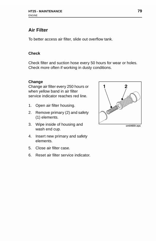
HT25 - MAINTENANCE 79ENGINE
Air Filter
To better access air filter, slide out overflow tank.
Check
Check filter and suction hose every 50 hours for wear or holes. Check more often if working in dusty conditions.
ChangeChange air filter every 250 hours or when yellow band in air filter service indicator reaches red line.
1. Open air filter housing.
2. Remove primary (2) and safety (1) elements.
3. Wipe inside of housing and wash end cup.
4. Insert new primary and safety elements.
5. Close air filter case.
6. Reset air filter service indicator.
om0465h.eps
1 2
HT25 - MAINTENANCE 79ENGINE
Air Filter
To better access air filter, slide out overflow tank.
Check
Check filter and suction hose every 50 hours for wear or holes. Check more often if working in dusty conditions.
ChangeChange air filter every 250 hours or when yellow band in air filter service indicator reaches red line.
1. Open air filter housing.
2. Remove primary (2) and safety (1) elements.
3. Wipe inside of housing and wash end cup.
om0465h.eps
1 2
4. Insert new primary and safety elements.
5. Close air filter case.
6. Reset air filter service indicator.
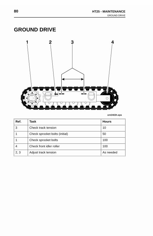
80 HT25 - MAINTENANCEGROUND DRIVE
80 HT25 - MAINTENANCEGROUND DRIVE
GROUND DRIVE
Ref. Task Hours
3 Check track tension 10
1 Check sprocket bolts (initial) 50
1 Check sprocket bolts 100
4 Check front idler roller 100
2, 3 Adjust track tension As needed
GRO
Ref.
3
1
1
4
2, 3
UND DRIVE
Task Hours
Check track tension 10
Check sprocket bolts (initial) 50
Check sprocket bolts 100
Check front idler roller 100
Adjust track tension As needed
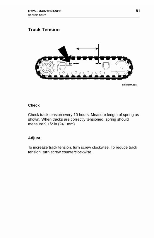
HT25 - MAINTENANCE 81GROUND DRIVE
Track Tension
Check
Check track tension every 10 hours. Measure length of spring as shown. When tracks are correctly tensioned, spring should measure 9 1/2 in (241 mm).
Adjust
To increase track tension, turn screw clockwise. To reduce track tension, turn screw counterclockwise.

82 HT25 - MAINTENANCEGROUND DRIVE
82 HT25 - MAINTENANCEGROUND DRIVE
Track Sprocket Bolts
Check sprocket bolts after first 50 hours and every 100 hours thereafter. Torque bolts to 70 ft•lb (95 N•m).
Front Idler Roller
Check front idler roller for wear every 100 hours. Replace if needed.
Track
Checktherea
Front
Checkneede
Sprocket Bolts
sprocket bolts after first 50 hours and every 100 hours fter. Torque bolts to 70 ft•lb (95 N•m).
Idler Roller
front idler roller for wear every 100 hours. Replace if d.

HT25 - MAINTENANCE 83HYDRAULICS
HYDRAULICS
NOTICE: Before disconnecting any hydraulic line, turn engine off and operate all controls to relieve pressure. Lower, block or support any raised component. Cover connection with heavy cloth and loosen connector nut slightly to relieve residual pressure. Catch all fluid in container.
Hoses
Check hoses every 10 hours for wear or damage. Replace as needed.
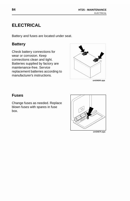
84 HT25 - MAINTENANCEELECTRICAL
84 HT25 - MAINTENANCEELECTRICAL
ELECTRICAL
Battery and fuses are located under seat.
Battery
Check battery connections for wear or corrosion. Keep connections clean and tight. Batteries supplied by factory are maintenance-free. Service replacement batteries according to manufacturer’s instructions.
Fuses
Change fuses as needed. Replace blown fuses with spares in fuse box.
om0464h.eps
ELE
Batter
Batte
Checkwear oconneBatterimaintereplacmanuf
Fuse
Changblown box.
CTRICAL
y and fuses are located under seat.
ry
battery connections for r corrosion. Keep ctions clean and tight. es supplied by factory are nance-free. Service ement batteries according to acturer’s instructions.
s
e fuses as needed. Replace fuses with spares in fuse
om0464h.eps
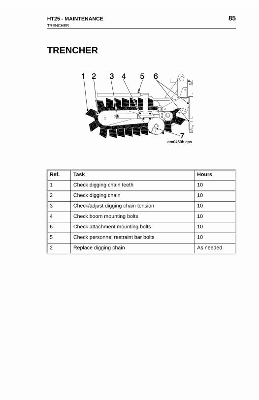
HT25 - MAINTENANCE 85TRENCHER
TRENCHER
Ref. Task Hours
1 Check digging chain teeth 10
2 Check digging chain 10
3 Check/adjust digging chain tension 10
4 Check boom mounting bolts 10
6 Check attachment mounting bolts 10
5 Check personnel restraint bar bolts 10
2 Replace digging chain As needed
HT25 - MAINTENANCE 85TRENCHER
TRENCHER
Ref. Task Hours
1 Check digging chain teeth 10
2 Check digging chain 10
3 Check/adjust digging chain tension 10
4 Check boom mounting bolts 10
6 Check attachment mounting bolts 10
5 Check personnel restraint bar bolts 10
2 Replace digging chain As needed
86 HT25 - MAINTENANCETRENCHER
86 HT25 - MAINTENANCETRENCHER
Teeth and Bits
Check teeth for wear every 10 hours. Replace worn teeth, using Ditch Witch replacement parts and maintaining original tooth pattern.
For more efficient digging, contact your Ditch Witch dealer for information about the tooth pattern best suited to your jobsite.
If using rock chain bits, check that bits rotate freely. Clean chain and check bits after each use. Replace bit when tungsten cap or insert is worn, or adapter can be damaged.
Chain
Check chain every 10 hours. Replace worn or broken chains. If sidebars are bent or loose on chain pins, chain spacers should be used to join sidebars.
Teeth
CheckDitch Wpattern
For moinform
If usingand chinsert
Chain
Checksidebaused t
and Bits
teeth for wear every 10 hours. Replace worn teeth, using itch replacement parts and maintaining original tooth
.
re efficient digging, contact your Ditch Witch dealer for ation about the tooth pattern best suited to your jobsite.
rock chain bits, check that bits rotate freely. Clean chain eck bits after each use. Replace bit when tungsten cap or is worn, or adapter can be damaged.
chain every 10 hours. Replace worn or broken chains. If rs are bent or loose on chain pins, chain spacers should be o join sidebars.
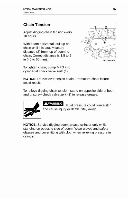
HT25 - MAINTENANCE 87TRENCHER
Chain Tension
Adjust digging chain tension every 10 hours.
With boom horizontal, pull up on chain until it is taut. Measure distance (2) from top of boom to chain. Correct distance is 1.5 to 2 in (40 to 50 mm).
To tighten chain, pump MPG into cylinder at check valve zerk (1).
NOTICE: Do not overtension chain. Premature chain failure could result.
To relieve digging chain tension, stand on opposite side of boom and unscrew check valve zerk (1) to release grease.
Fluid pressure could pierce skin and cause injury or death. Stay away.
NOTICE: Service digging boom grease cylinder only while standing on opposite side of boom. Wear gloves and safety glasses and cover fitting with cloth when relieving pressure in cylinder.
HT25 - MAINTENANCE 87TRENCHER
Chain Tension
Adjust digging chain tension every 10 hours.
With boom horizontal, pull up on chain until it is taut. Measure distance (2) from top of boom to chain. Correct distance is 1.5 to 2 in (40 to 50 mm).
To tighten chain, pump MPG into cylinder at check valve zerk (1).
NOTICE: Do not overtension chain. Premature chain failure could result.
To relieve digging chain tension, stand on opposite side of boom and unscrew check valve zerk (1) to release grease.
Fluid pressure could pierce skin
and cause injury or death. Stay away.NOTICE: Service digging boom grease cylinder only while standing on opposite side of boom. Wear gloves and safety glasses and cover fitting with cloth when relieving pressure in cylinder.
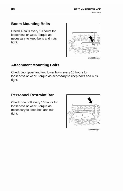
88 HT25 - MAINTENANCETRENCHER
88 HT25 - MAINTENANCETRENCHER
Boom Mounting Bolts
Check 4 bolts every 10 hours for looseness or wear. Torque as necessary to keep bolts and nuts tight.
Attachment Mounting Bolts
Check two upper and two lower bolts every 10 hours for looseness or wear. Torque as necessary to keep bolts and nuts tight.
Personnel Restraint Bar
Check one bolt every 10 hours for looseness or wear. Torque as necessary to keep bolt and nut tight.
Boom
Checkloosennecesstight.
Attac
Checkloosentight.
Perso
Checkloosennecesstight.
Mounting Bolts
4 bolts every 10 hours for ess or wear. Torque as ary to keep bolts and nuts
hment Mounting Bolts
two upper and two lower bolts every 10 hours for ess or wear. Torque as necessary to keep bolts and nuts
nnel Restraint Bar
one bolt every 10 hours for ess or wear. Torque as ary to keep bolt and nut
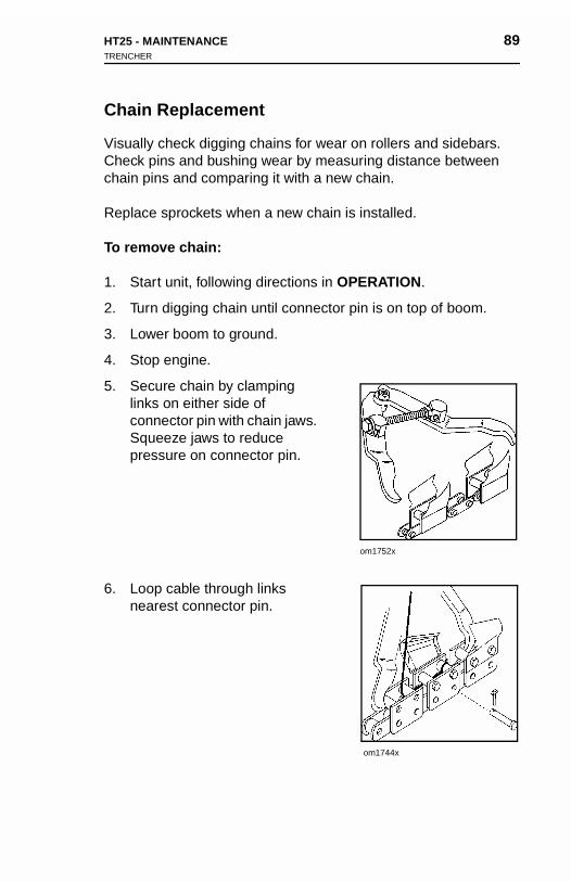
HT25 - MAINTENANCE 89TRENCHER
Chain Replacement
Visually check digging chains for wear on rollers and sidebars. Check pins and bushing wear by measuring distance between chain pins and comparing it with a new chain.
Replace sprockets when a new chain is installed.
To remove chain:
1. Start unit, following directions in OPERATION.
2. Turn digging chain until connector pin is on top of boom.
3. Lower boom to ground.
4. Stop engine.
5. Secure chain by clamping links on either side of connector pin with chain jaws. Squeeze jaws to reduce pressure on connector pin.
6. Loop cable through links nearest connector pin.
om1752x
om1744x
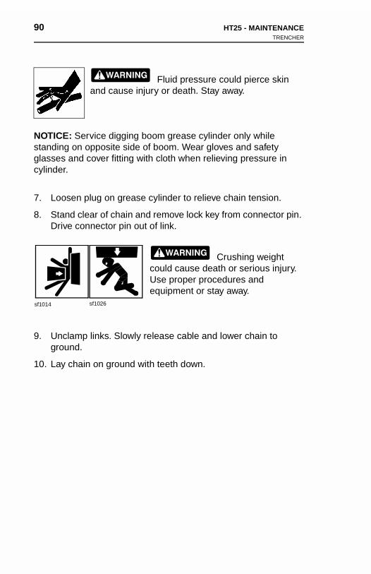
90 HT25 - MAINTENANCETRENCHER
90 HT25 - MAINTENANCETRENCHER
Fluid pressure could pierce skin and cause injury or death. Stay away.
NOTICE: Service digging boom grease cylinder only while standing on opposite side of boom. Wear gloves and safety glasses and cover fitting with cloth when relieving pressure in cylinder.
7. Loosen plug on grease cylinder to relieve chain tension.
8. Stand clear of chain and remove lock key from connector pin. Drive connector pin out of link.
Crushing weight could cause death or serious injury. Use proper procedures and equipment or stay away.
9. Unclamp links. Slowly release cable and lower chain to ground.
10. Lay chain on ground with teeth down.
sf1014 sf1026
NOTICstandinglassecylinde
7. Lo
8. StDr
9. Ungro
10. La
sf1014
Fluid pressure could pierce skin and cause injury or death. Stay away.
E: Service digging boom grease cylinder only while g on opposite side of boom. Wear gloves and safety
s and cover fitting with cloth when relieving pressure in r.
osen plug on grease cylinder to relieve chain tension.
and clear of chain and remove lock key from connector pin. ive connector pin out of link.
Crushing weight could cause death or serious injury. Use proper procedures and equipment or stay away.
clamp links. Slowly release cable and lower chain to
sf1026
und.
y chain on ground with teeth down.
HT25 - MAINTENANCE 91TRENCHER
To install chain:
1. Lay chain on ground with teeth down and pointed toward unit.
2. Start unit.
3. Back unit up until chain extends past head shaft about 1 ft (30.5 cm).
4. Lower backfill blade to ground.
5. Lower boom to horizontal position.
6. Stop engine.
7. Pull rear end of chain over and about 10 in (26 cm) past tail roller.
8. Use hoist to pull front end of chain over head shaft sprocket.
9. Move chain down boom until chain connector pin and lock key can be installed. Install connector pin and lock key.
10. Tighten chain by pumping EPG into grease cylinder.

92 HT25 - MAINTENANCE 92 HT25 - MAINTENANCE
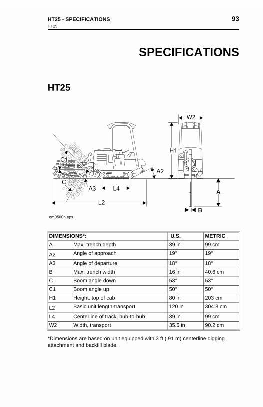
HT25 - SPECIFICATIONS 93HT25
SPECIFICATIONS
HT25
*Dimensions are based on unit equipped with 3 ft (.91 m) centerline digging attachment and backfill blade.
DIMENSIONS*: U.S. METRIC
A Max. trench depth 39 in 99 cm
A2 Angle of approach 19° 19°
A3 Angle of departure 18° 18°
B Max. trench width 16 in 40.6 cm
C Boom angle down 53° 53°
C1 Boom angle up 50° 50°
H1 Height, top of cab 80 in 203 cm
L2 Basic unit length-transport 120 in 304.8 cm
L4 Centerline of track, hub-to-hub 39 in 99 cm
W2 Width, transport 35.5 in 90.2 cm
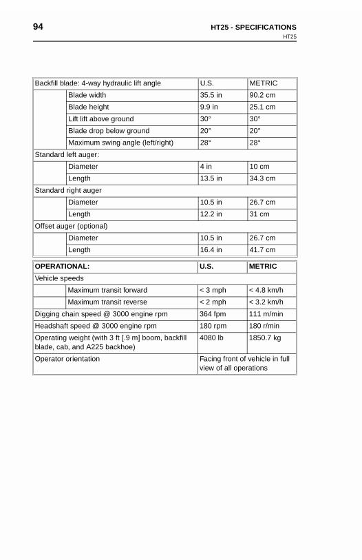
94 HT25 - SPECIFICATIONSHT25
94 HT25 - SPECIFICATIONSHT25
Backfill blade: 4-way hydraulic lift angle U.S. METRIC
Blade width 35.5 in 90.2 cm
Blade height 9.9 in 25.1 cm
Lift lift above ground 30° 30°
Blade drop below ground 20° 20°
Maximum swing angle (left/right) 28° 28°
Standard left auger:
Diameter 4 in 10 cm
Length 13.5 in 34.3 cm
Standard right auger
Diameter 10.5 in 26.7 cm
Length 12.2 in 31 cm
Offset auger (optional)
Diameter 10.5 in 26.7 cm
Length 16.4 in 41.7 cm
OPERATIONAL: U.S. METRIC
Vehicle speeds
Maximum transit forward < 3 mph < 4.8 km/h
Maximum transit reverse < 2 mph < 3.2 km/h
Digging chain speed @ 3000 engine rpm 364 fpm 111 m/min
Headshaft speed @ 3000 engine rpm 180 rpm 180 r/min
Operating weight (with 3 ft [.9 m] boom, backfill blade, cab, and A225 backhoe)
4080 lb 1850.7 kg
Operator orientation Facing front of vehicle in full view of all operations
Backfill
Standa
Standa
Offset a
OPERA
Vehicle
Digging
Headsh
Operatiblade, c
Operato
blade: 4-way hydraulic lift angle U.S. METRIC
Blade width 35.5 in 90.2 cm
Blade height 9.9 in 25.1 cm
Lift lift above ground 30° 30°
Blade drop below ground 20° 20°
Maximum swing angle (left/right) 28° 28°
rd left auger:
Diameter 4 in 10 cm
Length 13.5 in 34.3 cm
rd right auger
Diameter 10.5 in 26.7 cm
Length 12.2 in 31 cm
uger (optional)
Diameter 10.5 in 26.7 cm
Length 16.4 in 41.7 cm
TIONAL: U.S. METRIC
speeds
Maximum transit forward < 3 mph < 4.8 km/h
Maximum transit reverse < 2 mph < 3.2 km/h
chain speed @ 3000 engine rpm 364 fpm 111 m/min
aft speed @ 3000 engine rpm 180 rpm 180 r/min
ng weight (with 3 ft [.9 m] boom, backfill ab, and A225 backhoe)
4080 lb 1850.7 kg
r orientation Facing front of vehicle in full view of all operations
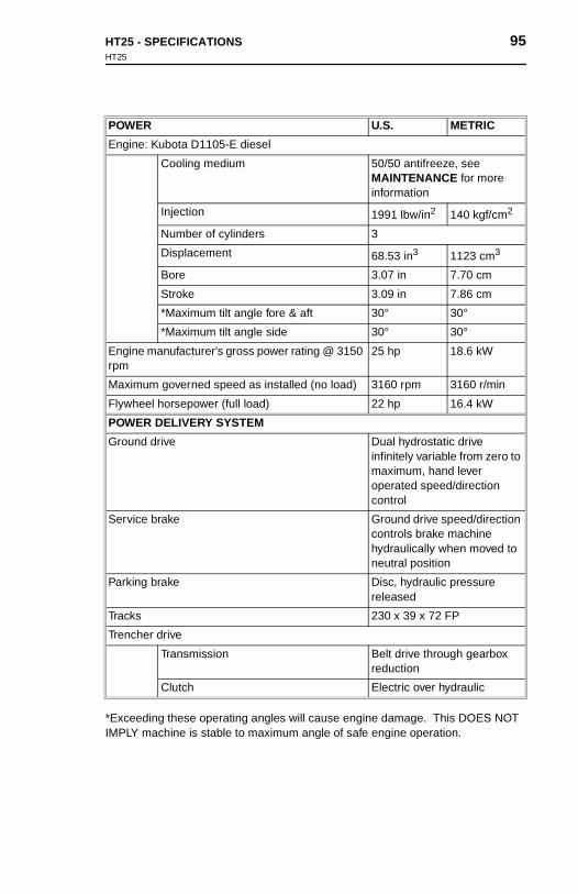
HT25 - SPECIFICATIONS 95HT25
*Exceeding these operating angles will cause engine damage. This DOES NOT IMPLY machine is stable to maximum angle of safe engine operation.
POWER U.S. METRIC
Engine: Kubota D1105-E diesel
Cooling medium 50/50 antifreeze, see MAINTENANCE for more information
Injection 1991 lbw/in2 140 kgf/cm2
Number of cylinders 3
Displacement 68.53 in3 1123 cm3
Bore 3.07 in 7.70 cm
Stroke 3.09 in 7.86 cm
*Maximum tilt angle fore & aft 30° 30°
*Maximum tilt angle side 30° 30°
Engine manufacturer's gross power rating @ 3150 rpm
25 hp 18.6 kW
Maximum governed speed as installed (no load) 3160 rpm 3160 r/min
Flywheel horsepower (full load) 22 hp 16.4 kW
POWER DELIVERY SYSTEM
Ground drive Dual hydrostatic drive infinitely variable from zero to maximum, hand lever operated speed/direction control
Service brake Ground drive speed/direction controls brake machine hydraulically when moved to neutral position
Parking brake Disc, hydraulic pressure released
Tracks 230 x 39 x 72 FP
Trencher drive
Transmission Belt drive through gearbox reduction
Clutch Electric over hydraulic
HT25 - SPECIFICATIONS 95HT25
POWER U.S. METRIC
Engine: Kubota D1105-E diesel
Cooling medium 50/50 antifreeze, see MAINTENANCE for more information
Injection 1991 lbw/in2 140 kgf/cm2
Number of cylinders 3
Displacement 68.53 in3 1123 cm3
Bore 3.07 in 7.70 cm
Stroke 3.09 in 7.86 cm
*Maximum tilt angle fore & aft 30° 30°
*Maximum tilt angle side 30° 30°
Engine manufacturer's gross power rating @ 3150 rpm
25 hp 18.6 kW
Maximum governed speed as installed (no load) 3160 rpm 3160 r/min
Flywheel horsepower (full load) 22 hp 16.4 kW
POWER DELIVERY SYSTEM
Ground drive Dual hydrostatic drive infinitely variable from zero to maximum, hand lever operated speed/direction
*Exceeding these operating angles will cause engine damage. This DOES NOT IMPLY machine is stable to maximum angle of safe engine operation.
control
Service brake Ground drive speed/direction controls brake machine hydraulically when moved to neutral position
Parking brake Disc, hydraulic pressure released
Tracks 230 x 39 x 72 FP
Trencher drive
Transmission Belt drive through gearbox reduction
Clutch Electric over hydraulic
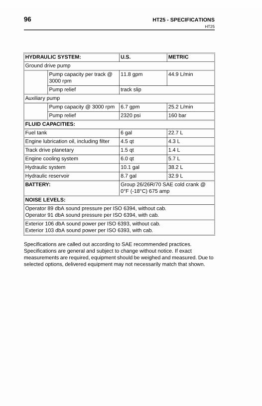
96 HT25 - SPECIFICATIONSHT25
96 HT25 - SPECIFICATIONSHT25
Specifications are called out according to SAE recommended practices. Specifications are general and subject to change without notice. If exact measurements are required, equipment should be weighed and measured. Due to selected options, delivered equipment may not necessarily match that shown.
HYDRAULIC SYSTEM: U.S. METRIC
Ground drive pump
Pump capacity per track @ 3000 rpm
11.8 gpm 44.9 L/min
Pump relief track slip
Auxiliary pump
Pump capacity @ 3000 rpm 6.7 gpm 25.2 L/min
Pump relief 2320 psi 160 bar
FLUID CAPACITIES:
Fuel tank 6 gal 22.7 L
Engine lubrication oil, including filter 4.5 qt 4.3 L
Track drive planetary 1.5 qt 1.4 L
Engine cooling system 6.0 qt 5.7 L
Hydraulic system 10.1 gal 38.2 L
Hydraulic reservoir 8.7 gal 32.9 L
BATTERY: Group 26/26R/70 SAE cold crank @ 0°F (-18°C) 675 amp
NOISE LEVELS:
Operator 89 dbA sound pressure per ISO 6394, without cab.Operator 91 dbA sound pressure per ISO 6394, with cab.
Exterior 106 dbA sound power per ISO 6393, without cab.Exterior 103 dbA sound power per ISO 6393, with cab.
SpecificSpecificmeasureselected
HYDRA
Ground
Auxiliar
FLUID
Fuel tan
Engine
Track d
Engine
Hydrau
Hydrau
BATTE
NOISE
OperatoOperato
ExterioExterio
ULIC SYSTEM: U.S. METRIC
drive pump
Pump capacity per track @ 3000 rpm
11.8 gpm 44.9 L/min
Pump relief track slip
y pump
Pump capacity @ 3000 rpm 6.7 gpm 25.2 L/min
Pump relief 2320 psi 160 bar
CAPACITIES:
k 6 gal 22.7 L
lubrication oil, including filter 4.5 qt 4.3 L
rive planetary 1.5 qt 1.4 L
cooling system 6.0 qt 5.7 L
lic system 10.1 gal 38.2 L
lic reservoir 8.7 gal 32.9 L
RY: Group 26/26R/70 SAE cold crank @ 0°F (-18°C) 675 amp
LEVELS:
r 89 dbA sound pressure per ISO 6394, without cab.r 91 dbA sound pressure per ISO 6394, with cab.
r 106 dbA sound power per ISO 6393, without cab.r 103 dbA sound power per ISO 6393, with cab.
ations are called out according to SAE recommended practices. ations are general and subject to change without notice. If exact ments are required, equipment should be weighed and measured. Due to options, delivered equipment may not necessarily match that shown.
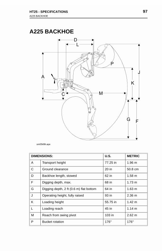
HT25 - SPECIFICATIONS 97A225 BACKHOE
A225 BACKHOE
DIMENSIONS: U.S. METRIC
A Transport height 77.25 in 1.96 m
C Ground clearance 20 in 50.8 cm
D Backhoe length, stowed 62 in 1.58 m
F Digging depth, max. 68 in 1.73 m
G Digging depth, 2 ft (0.6 m) flat bottom 64 in 1.63 m
J Operating height, fully raised 93 in 2.36 m
K Loading height 55.75 in 1.42 m
L Loading reach 45 in 1.14 m
M Reach from swing pivot 103 in 2.62 m
P Bucket rotation 176° 176°
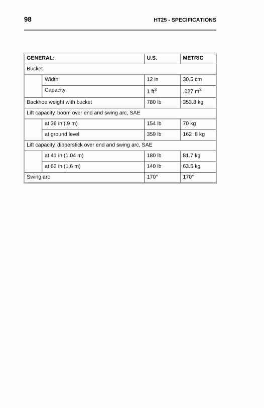
98 HT25 - SPECIFICATIONS 98 HT25 - SPECIFICATIONS
GENERAL: U.S. METRIC
Bucket
Width 12 in 30.5 cm
Capacity 1 ft3 .027 m3
Backhoe weight with bucket 780 lb 353.8 kg
Lift capacity, boom over end and swing arc, SAE
at 36 in (.9 m) 154 lb 70 kg
at ground level 359 lb 162 .8 kg
Lift capacity, dipperstick over end and swing arc, SAE
at 41 in (1.04 m) 180 lb 81.7 kg
at 62 in (1.6 m) 140 lb 63.5 kg
Swing arc 170° 170°
GENER
Bucket
Backho
Lift cap
Lift cap
Swing
AL: U.S. METRIC
Width 12 in 30.5 cm
Capacity 1 ft3 .027 m3
e weight with bucket 780 lb 353.8 kg
acity, boom over end and swing arc, SAE
at 36 in (.9 m) 154 lb 70 kg
at ground level 359 lb 162 .8 kg
acity, dipperstick over end and swing arc, SAE
at 41 in (1.04 m) 180 lb 81.7 kg
at 62 in (1.6 m) 140 lb 63.5 kg
arc 170° 170°

HT25 - WARRANTY 99
WARRANTY
Ditch Witch Equipment and PartsLimited Warranty Policy
Subject to the limitations and exclusions herein, free replacement parts will be provided at any authorized Ditch Witch dealership for any Ditch Witch equipment or parts manufactured by The Charles Machine Works, Inc. (CMW) that fail due to a defect in material or workmanship within one (1) year of first commercial use. Free labor will be provided at any authorized Ditch Witch dealership for installation of parts under this warranty during the first year following initial commercial use of the serial-numbered Ditch Witch equipment on which it is installed.
Exclusions from Product Warranty• Wear-related failure of parts subject to ground contact including, but not limited
to, digging teeth, digging chains, sprockets, backhoe buckets, plow blades, drill
pipe, drill bits, backreamers, and swivels.
• All incidental or consequential damages.
• All defects, damages, or injuries caused by misuse, abuse, improper
installation, alteration, neglect, or uses other than those for which products
were intended.
• All defects, damages, or injuries caused by improper training, operation, or
servicing of products in a manner inconsistent with manufacturer’s
recommendations.
• All engines and engine accessories (these are covered by original
manufacturer’s warranty).
• Tires, belts, and other parts which may be subject to another manufacturer’s
warranty (such warranty will be available to purchaser).
• All implied warranties not expressly stated herein, including any warranty of
fitness for a particular purpose and merchantability.
IF THE PRODUCTS ARE PURCHASED FOR COMMERCIAL PURPOSES AS DEFINED BY THE UNIFORM COMMERCIAL CODE, THEN THERE ARE NO WARRANTIES WHICH EXTEND BEYOND THE FACE HEREOF AND THERE ARE NO IMPLIED WARRANTIES OF ANY KIND WHICH EXTEND TO A COMMERCIAL BUYER. ALL OTHER PROVISIONS OF THIS LIMITED WARRANTY APPLY INCLUDING THE DUTIES IMPOSED.

100 HT25 - WARRANTY 100 HT25 - WARRANTY
Ditch Witch products have been tested to deliver acceptable performance in most conditions. This does not imply they will deliver acceptable performance in all conditions. Therefore, to assure suitability, products should be operated under anticipated working conditions prior to purchase.
Defects will be determined by an inspection within thirty (30) days of the date of failure of the product or part by CMW or its authorized dealer. CMW will provide the location of its inspection facilities or its nearest authorized dealer upon inquiry. CMW reserves the right to supply remanufactured replacements parts under this warranty as it deems appropriate.
Extended warranties are available upon request from your local Ditch Witch dealer or CMW.
Some states do not allow exclusion or limitation of incidental or consequential damages, so above limitation of exclusion may not apply. Further, some states do not allow exclusion of or limitation of how long an implied warranty lasts, so the above limitation may not apply. This limited warranty gives product owner specific legal rights and the product owner may also have other rights which vary from state to state.
For information regarding this limited warranty, contact CMW’s Product Support department, P.O. Box 66, Perry, OK 73077-0066, or contact your local Ditch Witch dealer.
First version: 1/91; Latest version: 4/00
Ditch Wconditioconditioanticipa
Defectsfailure othe locaCMW rewarranty
Extendedealer o
Some sdamagenot allowabove lilegal rigstate to
For infodepartmdealer.
First ver
itch products have been tested to deliver acceptable performance in most ns. This does not imply they will deliver acceptable performance in all ns. Therefore, to assure suitability, products should be operated under ted working conditions prior to purchase.
will be determined by an inspection within thirty (30) days of the date of f the product or part by CMW or its authorized dealer. CMW will provide tion of its inspection facilities or its nearest authorized dealer upon inquiry. serves the right to supply remanufactured replacements parts under this as it deems appropriate.
d warranties are available upon request from your local Ditch Witch r CMW.
tates do not allow exclusion or limitation of incidental or consequential s, so above limitation of exclusion may not apply. Further, some states do exclusion of or limitation of how long an implied warranty lasts, so the
mitation may not apply. This limited warranty gives product owner specific hts and the product owner may also have other rights which vary from state.
rmation regarding this limited warranty, contact CMW’s Product Support ent, P.O. Box 66, Perry, OK 73077-0066, or contact your local Ditch Witch
sion: 1/91; Latest version: 4/00


HT25 - 103
HT25 - 103