Embed Size (px)
Citation preview
DIVISION OF BIOMEDICAL SCIENCESGROSS ANATOMY SUITE STUDY
FINALDECEMBER 6, 2006
prepared by
DIVISION OF BIOMEDICAL SCIENCESGROSS ANATOMY SUITE STUDY
DECEMBER 6, 2006
TABLE OF CONTENTS
ii
ACKNOWLEDGEMENTS
1.0 EXECUTIVE SUMMARY PAGE
1.1 OVERVIEW 5
2.0 PROGRAM REQUIREMENTS
2.1 SPACE PROGRAM SUMMARY 6 2.2 SPACE DESCRIPTIONS 7
2.3 SPECIAL DESIGN REQUIREMENTS 9 2.3.1 ACCESSIBILITY
2.4 HVAC DESIGN PARAMETERS 10
3.0 DESIGN ORGANIZATION
3.1 DESIGN SCHEMES 11 • GROSS ANATOMY SUITE
• CLASS LAB
4.0 TECHNICAL DESIGN CRITERIA
4.1 MECHANICAL 23 4.2 ELECTRICAL SYSTEMS 32 4.3 PLUMBING AND FIRE PROTECTION 40 4.4 FIRE ALARM SYSTEM 43 4.5 TELECOMMUNICATIONS SYSTEMS 43 4.6 SECURITY 43 4.7 A/V TECHNOLOGY 43 4.8 APPLICABLE CODES AND REGULATIONS 44
5.0 BUDGET AND COST ANALYSIS
5.1 ESTIMATE SUMMARY 48
6.0 PROJECT SCHEDULE
DIVISION OF BIOMEDICAL SCIENCESGROSS ANATOMY SUITE STUDY
DECEMBER 6, 2006
TABLE OF CONTENTS
iii
APPENDICES
A1.0 DETAILED SPACE REQUIREMENTS AND DIAGRAMS
A2.0 MEETING MINUTES
A3.0 DETAILED COST PLAN
M1.0 MECHANICAL SYSTEM SKETCHES
M2.0 LAMINAR FLOW DIFFUSER
M3.0 ACH SCHEDULE
DIVISION OF BIOMEDICAL SCIENCESGROSS ANATOMY SUITE STUDY
DECEMBER 6, 2006
ACKNOWLEDGEMENTS
iv
Tim Ralston, Assistant Vice Chancellor
Kieron Brunelle, Principal Educational Facilities Planner
Bill Johnson, Senior Educational Facilities Planner
Berent Pippert, Campus Space Manager
Craig V. Byus, Dean and Program Director, Divison of Biomedical Sciences
Neal L. Schiller, Associate Dean & Chair of the Division,
Divison of Biomedical Sciences
Faye Dawson Brock, Director of Instructional Support Unit,
Divison of Biomedical Sciences
Lynn Hice, Management Services Officer, Divison of Biomedical Sciences
James Colgan, Lecturer, Divison of Biomedical Sciences
CAPITAL AND PHYSICAL PLANNING
FOCUS GROUP, BIOMEDICAL SCIENCES
LIST OF PARTICIPANTS
DIVISION OF BIOMEDICAL SCIENCESGROSS ANATOMY SUITE STUDY
DECEMBER 6, 2006
ACKNOWLEDGEMENTS
v
CO Architects Los Angeles5055 Wilshire Boulevard, Suite 900Los Angeles, CA 90036Office: (323) 525-0500, Fax: (323) 525-0955
Scott P. Kelsey, Principal-in-Charge
Jonathan Kanda, Project Architect
Duke Sakiyabu, Designer
Consulting Solutions Inc.10650 Scripps Ranch Boulevard, Suite 210San Diego, CA 92131Office: (858) 564-3777, Fax: (858) 564-3799
Pervez Mobin, PE, Principal
Davis Langdon301 Arizona Avenue, Suite 301Santa Monica, CA 90401Office: (310) 393-9411, Fax: (310) 393-7493
Chris Sterparn, Associate
ARCHITECTURE
MEP
COST ESTIMATING
CONSULTANT TEAM
DIVISION OF BIOMEDICAL SCIENCESGROSS ANATOMY SUITE STUDY
DECEMBER 6, 2006
EXECUTIVE SUMMARY1.0
5
1.1 OVERVIEW
The following study defines the project scope of the proposed facilities renovation for the Division of Biomedical Sciences (Biomed) at the Uni-versity of California, Riverside (UCR). The facilities are located primarily on the basement level of the Statistics Computer Building (Stat Comp) on the UCR campus. There are additional offices on the first floor of the Stat Comp building as well as two portable trailers adjacent to the campus greenhouses. The proposed renovation is comprised of 1,590 assignable square feet (ASF) in class lab space and 2,115 ASF in a gross anatomy suite, both of which are located at the basement level of the Stat Comp building. The purpose of the study is to establish the goals, parameters and constraints of the project in sufficient detail to provide conceptual guidance for the subsequent design phases of the project and to confirm the estimated construction cost.
In conjunction with long term UCR Academic Planning goals, the Biomed program is expected to increase class size from twenty-four to forty stu-dents. This growth, coupled with the poor condition and inefficient use of the class lab space and gross anatomy lab, presents the main impetus for renovation of these facilities. The goals of this project include the follow-ing:
• Allow for a significant increase in students and create, where possible, more efficient layout of space to accommodate that growth.
• Increase safety and security.• Bring all renovated spaces into compliance with applicable codes and
regulations.• Facilitate potential upgrades in audiovisual infrastructure and equip-
ment.
DIVISION OF BIOMEDICAL SCIENCESGROSS ANATOMY SUITE STUDY
DECEMBER 6, 2006
PROGRAM REQUIREMENTS2.0
6
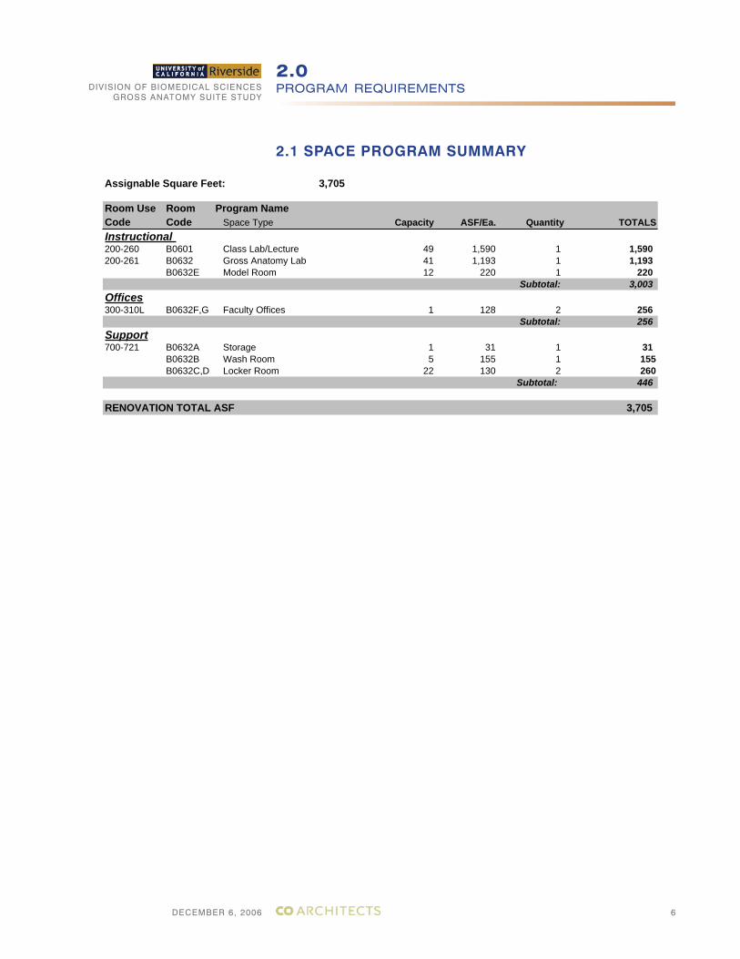
2.1 SPACE PROGRAM SUMMARY
Assignable Square Feet: 3,705
Room Use Room Program NameCode Code Space Type Capacity ASF/Ea. Quantity TOTALSInstructional200-260 B0601 Class Lab/Lecture 49 1,590 1 1,590200-261 B0632 Gross Anatomy Lab 41 1,193 1 1,193
B0632E Model Room 12 220 1 220Subtotal: 3,003
Offices300-310L B0632F,G Faculty Offices 1 128 2 256
Subtotal: 256Support700-721 B0632A Storage 1 31 1 31
B0632B Wash Room 5 155 1 155B0632C,D Locker Room 22 130 2 260
Subtotal: 446
RENOVATION TOTAL ASF 3,705
DIVISION OF BIOMEDICAL SCIENCESGROSS ANATOMY SUITE STUDY
DECEMBER 6, 2006
PROGRAM REQUIREMENTS2.0
7
2.2 SPACE DESCRIPTIONS
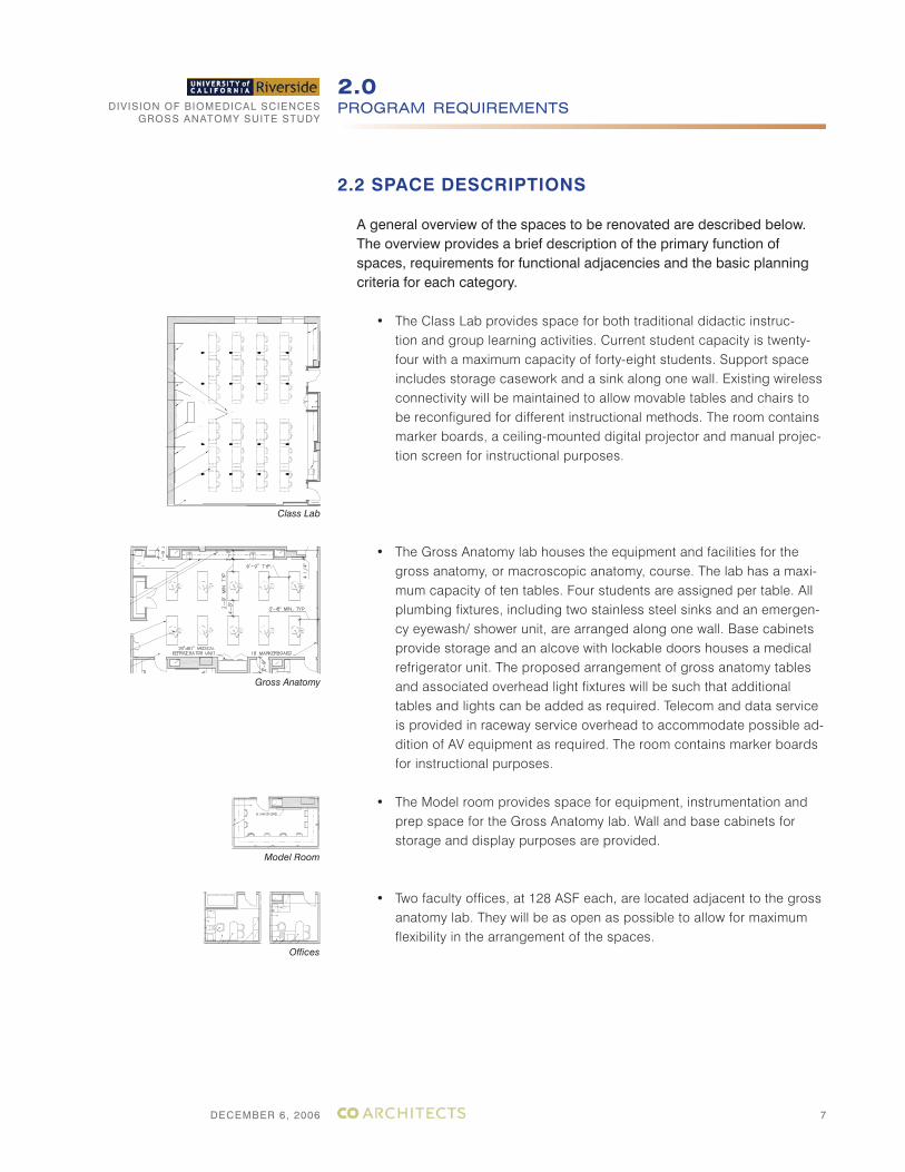
A general overview of the spaces to be renovated are described below. The overview provides a brief description of the primary function of spaces, requirements for functional adjacencies and the basic planning criteria for each category.
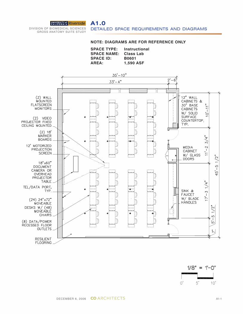
• The Class Lab provides space for both traditional didactic instruc-tion and group learning activities. Current student capacity is twenty-four with a maximum capacity of forty-eight students. Support space includes storage casework and a sink along one wall. Existing wireless connectivity will be maintained to allow movable tables and chairs to be reconfigured for different instructional methods. The room contains marker boards, a ceiling-mounted digital projector and manual projec-tion screen for instructional purposes.
• The Gross Anatomy lab houses the equipment and facilities for the gross anatomy, or macroscopic anatomy, course. The lab has a maxi-mum capacity of ten tables. Four students are assigned per table. All plumbing fixtures, including two stainless steel sinks and an emergen-cy eyewash/ shower unit, are arranged along one wall. Base cabinets provide storage and an alcove with lockable doors houses a medical refrigerator unit. The proposed arrangement of gross anatomy tables and associated overhead light fixtures will be such that additional tables and lights can be added as required. Telecom and data service is provided in raceway service overhead to accommodate possible ad-dition of AV equipment as required. The room contains marker boards for instructional purposes.
• The Model room provides space for equipment, instrumentation and prep space for the Gross Anatomy lab. Wall and base cabinets for storage and display purposes are provided.
• Two faculty offices, at 128 ASF each, are located adjacent to the gross
anatomy lab. They will be as open as possible to allow for maximum flexibility in the arrangement of the spaces.
Class Lab
Gross Anatomy
Model Room
Offices
DIVISION OF BIOMEDICAL SCIENCESGROSS ANATOMY SUITE STUDY
DECEMBER 6, 2006
PROGRAM REQUIREMENTS2.0
8
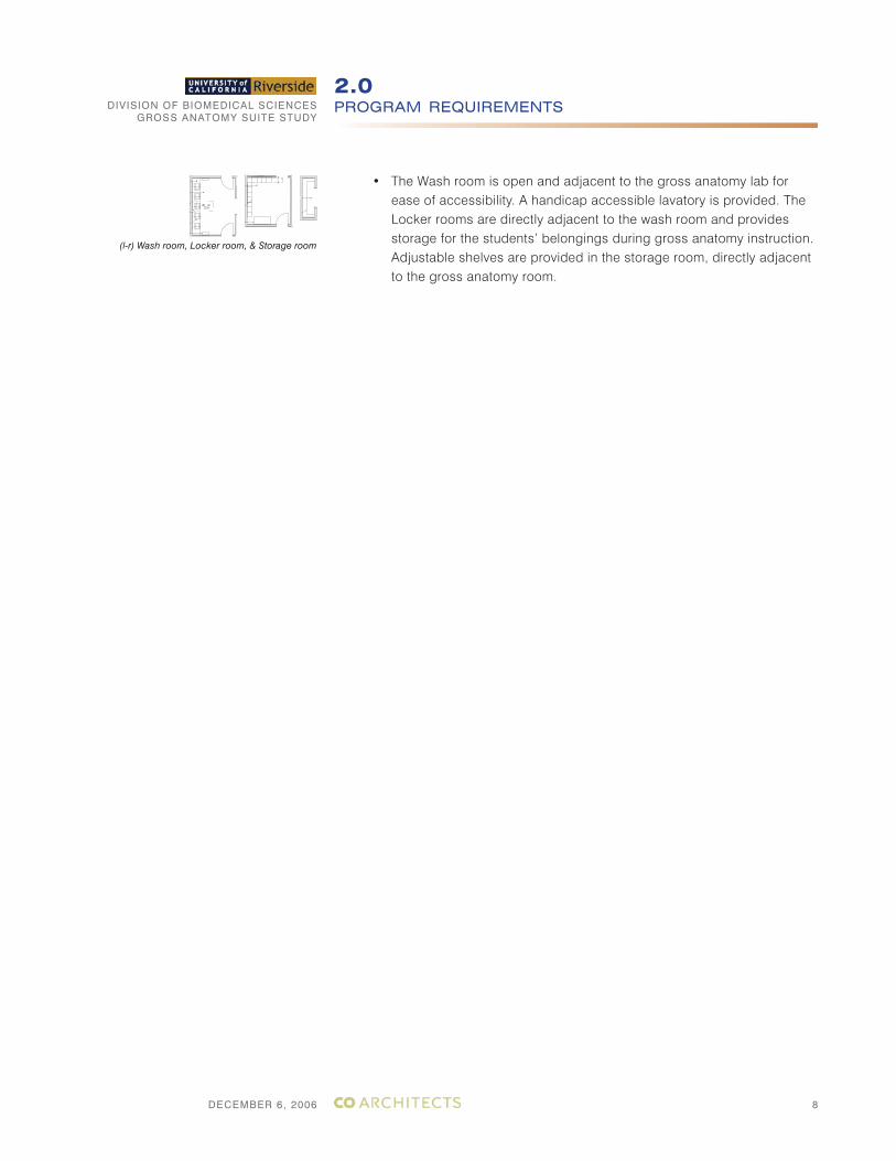
• The Wash room is open and adjacent to the gross anatomy lab for ease of accessibility. A handicap accessible lavatory is provided. The Locker rooms are directly adjacent to the wash room and provides storage for the students’ belongings during gross anatomy instruction. Adjustable shelves are provided in the storage room, directly adjacent to the gross anatomy room.
(l-r) Wash room, Locker room, & Storage room
DIVISION OF BIOMEDICAL SCIENCESGROSS ANATOMY SUITE STUDY
DECEMBER 6, 2006
PROGRAM REQUIREMENTS2.0
9
2.3 SPECIAL DESIGN REQUIREMENTS
2.3.1 ACCESSIBILITY
Providing accessibility for persons with disabilities requires special design considerations. The facility must conform to applicable local, state and federal regulations. Early design consideration should be given to the following accessibility aspects:
• Accessible work stations should be provided in the laboratories based on code requirements.
• Location of accessible work stations as close as possible to eyewash and safety showers.
• An 18” clearance on the pull side and 12” clearance on the push side of doors opposite the hinged side is required.
Some general criteria and guidelines for accessible work stations are as follows:
Work surfaces should be located 30” to 34” above the floor with wheel-chair clearance below. Adjustable work surfaces can provide a range of possible height adjustments.
Service controls, equipment, and equipment controls should be located within easy reach for persons with limited mobility. Controls require have single-action levers or blade handles for easy operation.
Aisle widths and clearances should be adequate for maneuvers of wheel-chair bound individuals based on code requirements.
DIVISION OF BIOMEDICAL SCIENCESGROSS ANATOMY SUITE STUDY
DECEMBER 6, 2006
PROGRAM REQUIREMENTS2.0
1010
2.4 HVAC DESIGN PARAMETERS
SafetyThe laboratory HVAC system should promote the safe operation of the building and the health and comfort of the occupants. The laboratory environment may contain harmful chemical vapors, particulates and biological aerosols. These hazardous substances must be continuously removed from the breathing zone of the laboratory users. Specifically, formaldehyde exposure within the Gross Anatomy suite should conform to CalOSHA requirements (California Code of Regulations, Title 8, Section 5217).
The HVAC design will be based on regulatory requirements and guide-lines along with good engineering practices. Code requirements are a minimum standard.
ContainmentContainment is provided by the negative pressure of the gross anatomy space relative to corridors and surrounding non-lab spaces. To effec-tively maintain the negative pressure in the lab, doors to the lab should be equipped with closers, must remain closed as much as possible and should not be held open.
The gross anatomy space will be continuously ventilated 24 hours a day.
Supply air shall be effectively distributed into all portions of the laboratory space by ceiling diffusers or perforated ceiling panels.
Air from the Gross Anatomy lab and other spaces which might contain hazardous materials or odors shall be exhausted outdoors and not recir-culated.
Air from offices and other clean areas may be recirculated or directed toward negative pressure laboratories.
DIVISION OF BIOMEDICAL SCIENCESGROSS ANATOMY SUITE STUDY
DECEMBER 6, 2006
DESIGN ORGANIZATION3.0
11
3.1 DESIGN SCHEMES
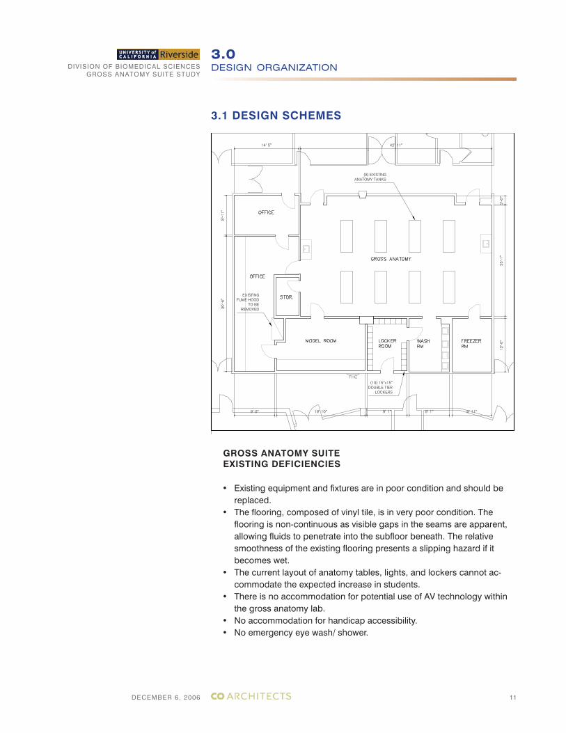
GROSS ANATOMY SUITEEXISTING DEFICIENCIES
• Existing equipment and fixtures are in poor condition and should be replaced.
• The flooring, composed of vinyl tile, is in very poor condition. The flooring is non-continuous as visible gaps in the seams are apparent, allowing fluids to penetrate into the subfloor beneath. The relative smoothness of the existing flooring presents a slipping hazard if it becomes wet.
• The current layout of anatomy tables, lights, and lockers cannot ac-commodate the expected increase in students.
• There is no accommodation for potential use of AV technology within the gross anatomy lab.
• No accommodation for handicap accessibility.• No emergency eye wash/ shower.
DIVISION OF BIOMEDICAL SCIENCESGROSS ANATOMY SUITE STUDY
DECEMBER 6, 2006
DESIGN ORGANIZATION3.0
12
3.1 DESIGN SCHEMES
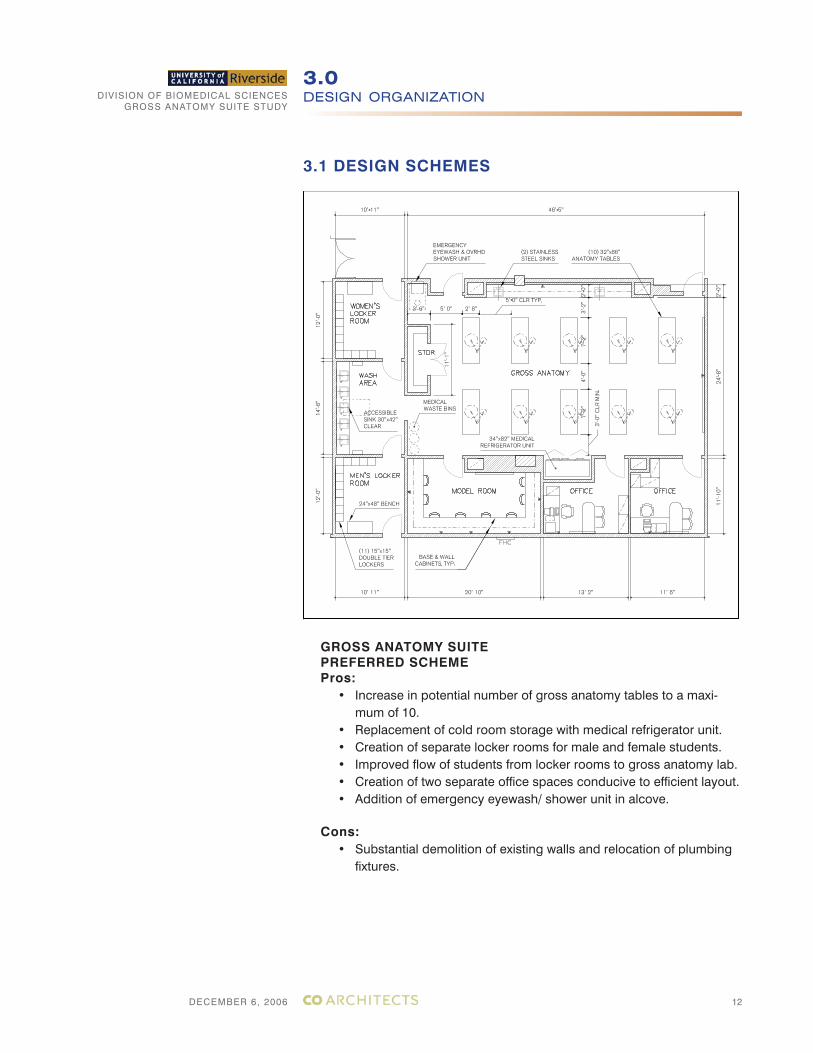
GROSS ANATOMY SUITEPREFERRED SCHEMEPros:
• Increase in potential number of gross anatomy tables to a maxi-mum of 10.
• Replacement of cold room storage with medical refrigerator unit.• Creation of separate locker rooms for male and female students.• Improved flow of students from locker rooms to gross anatomy lab.• Creation of two separate office spaces conducive to efficient layout.• Addition of emergency eyewash/ shower unit in alcove.
Cons:• Substantial demolition of existing walls and relocation of plumbing
fixtures.
DIVISION OF BIOMEDICAL SCIENCESGROSS ANATOMY SUITE STUDY
DECEMBER 6, 2006
DESIGN ORGANIZATION3.0
13
3.1 DESIGN SCHEMES
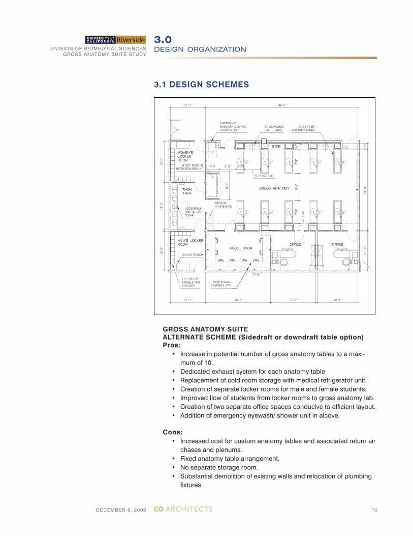
GROSS ANATOMY SUITEALTERNATE SCHEME (Sidedraft or downdraft table option)Pros:
• Increase in potential number of gross anatomy tables to a maxi-mum of 10.
• Dedicated exhaust system for each anatomy table• Replacement of cold room storage with medical refrigerator unit.• Creation of separate locker rooms for male and female students.• Improved flow of students from locker rooms to gross anatomy lab.• Creation of two separate office spaces conducive to efficient layout.• Addition of emergency eyewash/ shower unit in alcove.
Cons:• Increased cost for custom anatomy tables and associated return air
chases and plenums.• Fixed anatomy table arrangement.• No separate storage room.• Substantial demolition of existing walls and relocation of plumbing
fixtures.
DIVISION OF BIOMEDICAL SCIENCESGROSS ANATOMY SUITE STUDY
DECEMBER 6, 2006
DESIGN ORGANIZATION3.0
14
3.1 DESIGN PROCESS (FOR REFERENCE ONLY)
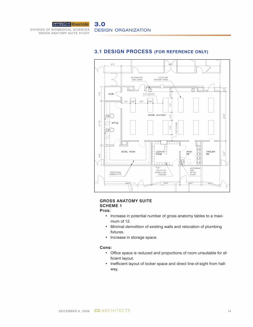
GROSS ANATOMY SUITESCHEME 1Pros:
• Increase in potential number of gross anatomy tables to a maxi-mum of 12.
• Minimal demolition of existing walls and relocation of plumbing fixtures.
• Increase in storage space.
Cons:• Office space is reduced and proportions of room unsuitable for ef-
ficient layout.• Inefficient layout of locker space and direct line-of-sight from hall-
way.
DIVISION OF BIOMEDICAL SCIENCESGROSS ANATOMY SUITE STUDY
DECEMBER 6, 2006
DESIGN ORGANIZATION3.0
15
3.1 DESIGN PROCESS (FOR REFERENCE ONLY)
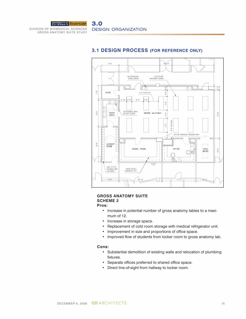
GROSS ANATOMY SUITESCHEME 2Pros:
• Increase in potential number of gross anatomy tables to a maxi-mum of 12.
• Increase in storage space.• Replacement of cold room storage with medical refrigerator unit.• Improvement in size and proportions of office space.• Improved flow of students from locker room to gross anatomy lab.
Cons:• Substantial demolition of existing walls and relocation of plumbing
fixtures. • Separate offices preferred to shared office space.• Direct line-of-sight from hallway to locker room.
DIVISION OF BIOMEDICAL SCIENCESGROSS ANATOMY SUITE STUDY
DECEMBER 6, 2006
DESIGN ORGANIZATION3.0
16
3.1 DESIGN PROCESS (FOR REFERENCE ONLY)
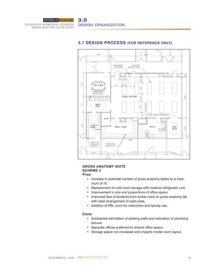
GROSS ANATOMY SUITESCHEME 3Pros:
• Increase in potential number of gross anatomy tables to a maxi-mum of 10.
• Replacement of cold room storage with medical refrigerator unit.• Improvement in size and proportions of office space.• Improved flow of students from locker room to gross anatomy lab
with ideal arrangement of wash area.• Addition of PBL room for instruction and faculty use.
Cons:• Substantial demolition of existing walls and relocation of plumbing
fixtures. • Separate offices preferred to shared office space.• Storage space not increased and impacts model room layout.
DIVISION OF BIOMEDICAL SCIENCESGROSS ANATOMY SUITE STUDY
DECEMBER 6, 2006
DESIGN ORGANIZATION3.0
17
3.1 DESIGN PROCESS (FOR REFERENCE ONLY)
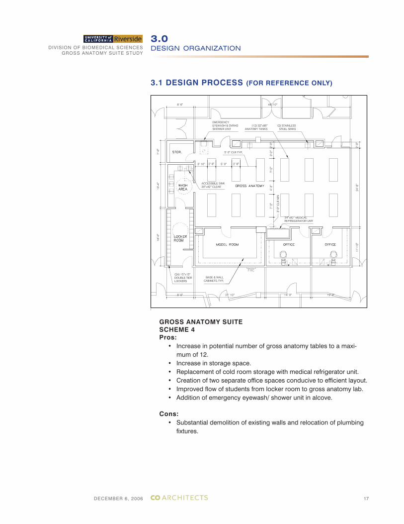
GROSS ANATOMY SUITESCHEME 4Pros:
• Increase in potential number of gross anatomy tables to a maxi-mum of 12.
• Increase in storage space.• Replacement of cold room storage with medical refrigerator unit.• Creation of two separate office spaces conducive to efficient layout.• Improved flow of students from locker room to gross anatomy lab.• Addition of emergency eyewash/ shower unit in alcove.
Cons:• Substantial demolition of existing walls and relocation of plumbing
fixtures.
DIVISION OF BIOMEDICAL SCIENCESGROSS ANATOMY SUITE STUDY
DECEMBER 6, 2006
DESIGN ORGANIZATION3.0
18
3.1 DESIGN SCHEMES
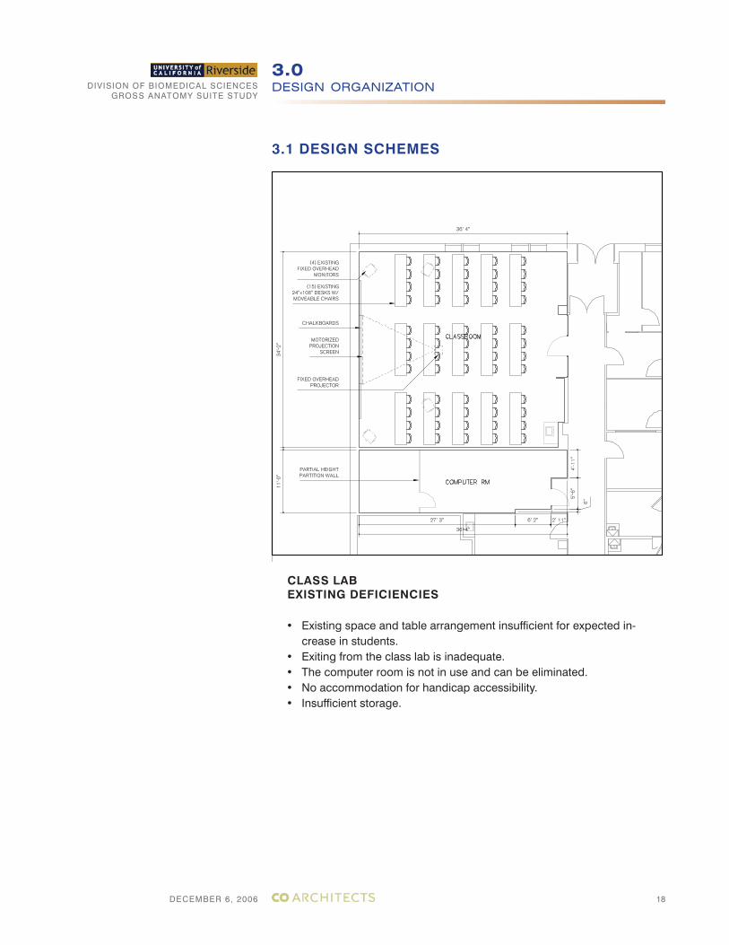
CLASS LABEXISTING DEFICIENCIES
• Existing space and table arrangement insufficient for expected in-crease in students.
• Exiting from the class lab is inadequate. • The computer room is not in use and can be eliminated.• No accommodation for handicap accessibility.• Insufficient storage.
DIVISION OF BIOMEDICAL SCIENCESGROSS ANATOMY SUITE STUDY
DECEMBER 6, 2006
DESIGN ORGANIZATION3.0
19
3.1 DESIGN SCHEMES
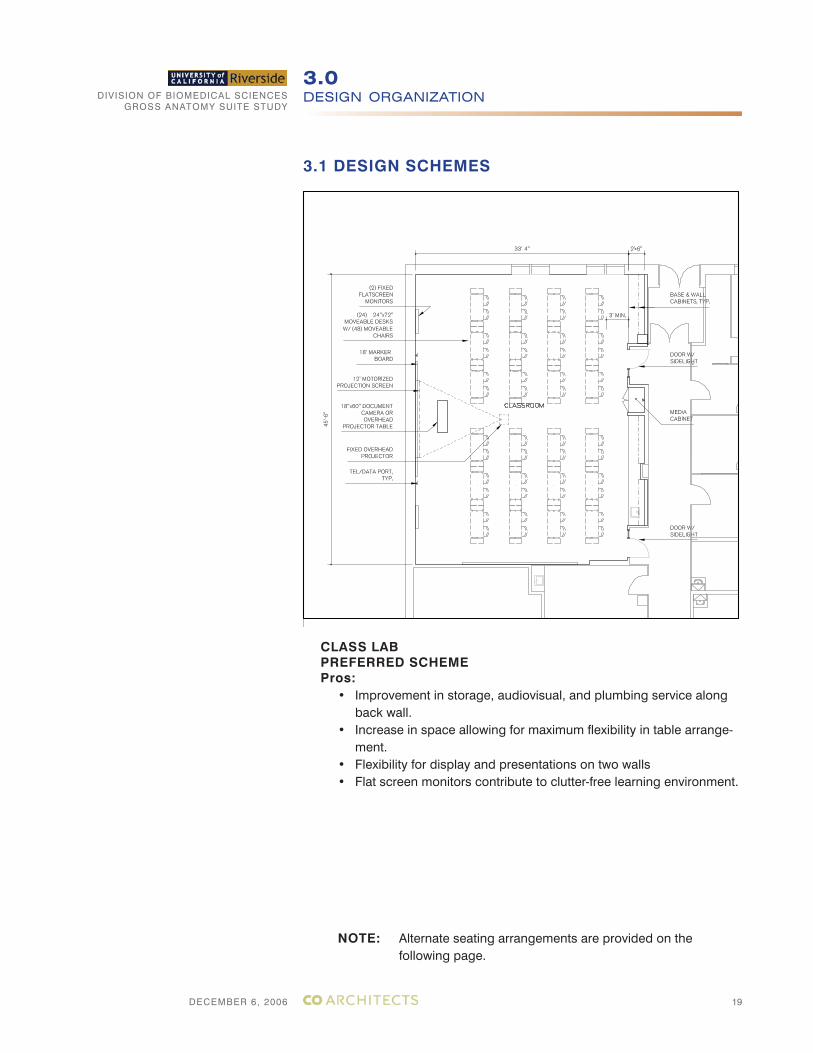
CLASS LABPREFERRED SCHEMEPros:
• Improvement in storage, audiovisual, and plumbing service along back wall.
• Increase in space allowing for maximum flexibility in table arrange-ment.
• Flexibility for display and presentations on two walls• Flat screen monitors contribute to clutter-free learning environment.
NOTE: Alternate seating arrangements are provided on the following page.
DIVISION OF BIOMEDICAL SCIENCESGROSS ANATOMY SUITE STUDY
DECEMBER 6, 2006
DESIGN ORGANIZATION3.0
20
3.1 DESIGN PROCESS (FOR REFERENCE ONLY)
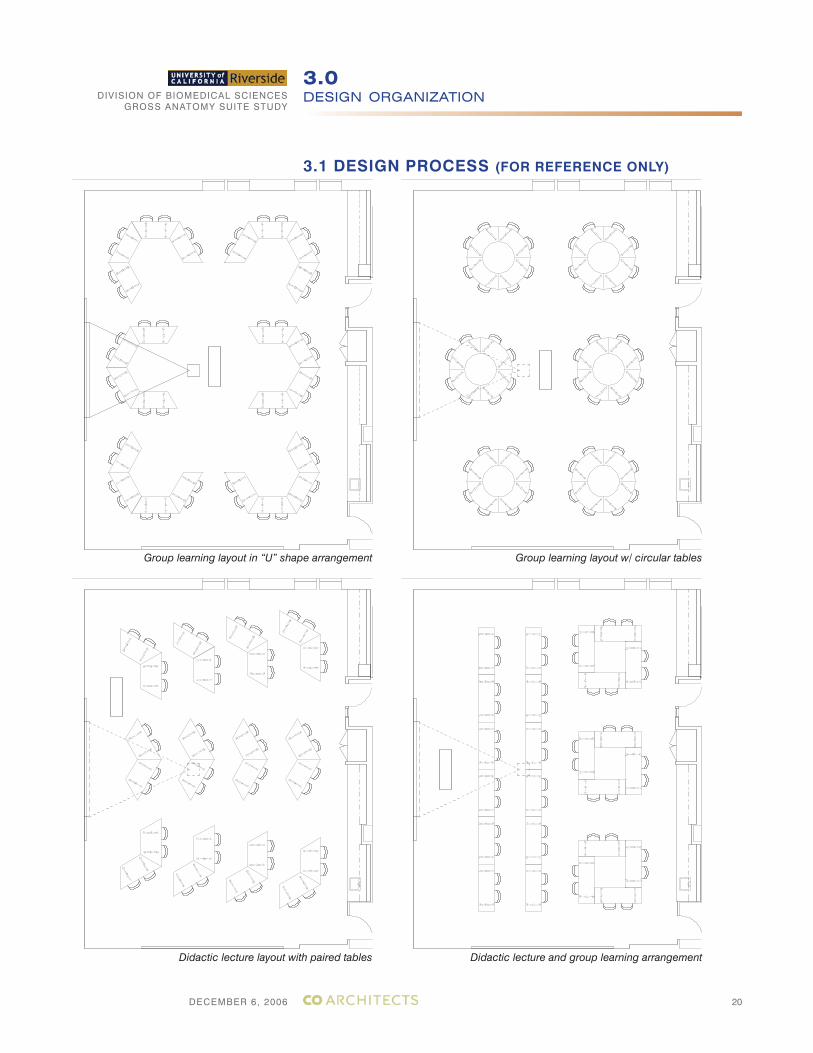
Group learning layout in “U” shape arrangement
Didactic lecture layout with paired tables
Group learning layout w/ circular tables
Didactic lecture and group learning arrangement
DIVISION OF BIOMEDICAL SCIENCESGROSS ANATOMY SUITE STUDY
DECEMBER 6, 2006
DESIGN ORGANIZATION3.0
21
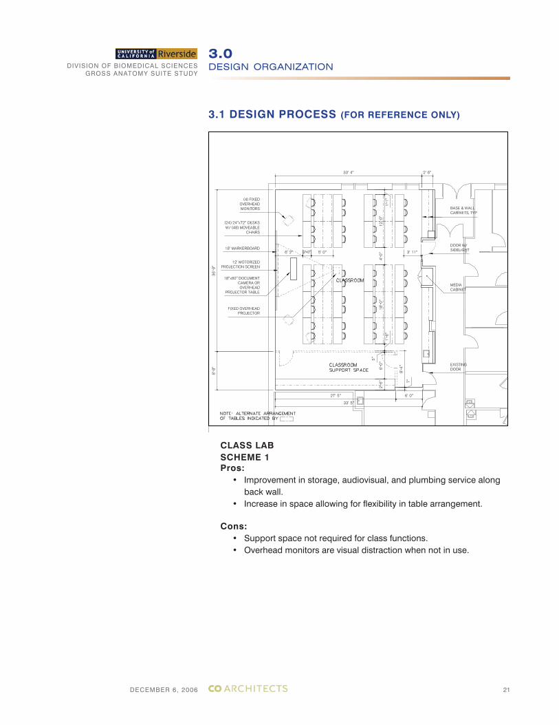
3.1 DESIGN PROCESS (FOR REFERENCE ONLY)
CLASS LABSCHEME 1Pros:
• Improvement in storage, audiovisual, and plumbing service along back wall.
• Increase in space allowing for flexibility in table arrangement.
Cons:• Support space not required for class functions.• Overhead monitors are visual distraction when not in use.
DIVISION OF BIOMEDICAL SCIENCESGROSS ANATOMY SUITE STUDY
DECEMBER 6, 2006
DESIGN ORGANIZATION3.0
22
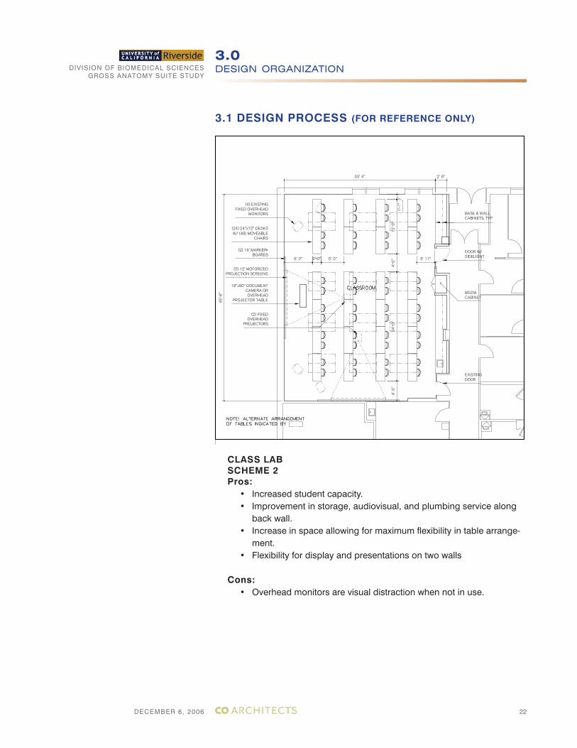
3.1 DESIGN PROCESS (FOR REFERENCE ONLY)
CLASS LABSCHEME 2Pros:
• Increased student capacity.• Improvement in storage, audiovisual, and plumbing service along
back wall.• Increase in space allowing for maximum flexibility in table arrange-
ment.• Flexibility for display and presentations on two walls
Cons:• Overhead monitors are visual distraction when not in use.
DIVISION OF BIOMEDICAL SCIENCESGROSS ANATOMY SUITE STUDY
DECEMBER 6, 2006
TECHNICAL DESIGN CRITERIA4.0
23
4.1 MECHANICAL
4.1.1 GENERAL
The mechanical systems considered included heating, ventilation and air conditioning for the project:
1. Codes and standards.
• California Building Code - 2001• California Mechanical Code, 2001• California Plumbing Code, 2001• California Electrical Code, 2004• California Energy Code (Title 24, Part 6), 1998• California Code Regulation for Elevators (Title 24, Part 6), 1998• California Fire Codes (UBC-1997, NFPA72-1996, NEC-1996), 1998• California State Referenced Standard Code (Title 24, Part 12), 1998• Cal OHSA (Title 8), 1998• National Fire Protection Association (NFPA)• NFPA 30 - Flammable and Combustible Liquids Code, 1996• NFPA 45 - Fire Protection for Laboratories using Chemicals, 1996• NFPA 101 - Safety to Life from Fire in Buildings and Structures, 1997• CFR 1910.1450 - Occupational Exposures to Hazardous Chemicals in
Laboratories (OSHA Standard 29)• ADA - Americans with Disabilities Act Accessibility Guidelines
(ADAAG), U. S. Architectural and Transportation Barriers Compliance Board
• ANSI/CABO A117.1 - Access and Usable Buildings and Facilities, 1992• ANSI/AIHA Z9.5 - American National Standard for Laboratory Ventila-
tion, 1992• ANSI Z358.1 - Emergency Eyewash and Shower Equipment, 1998• HHS (CDC) 93-8395 - Biosafety in Microbiological and Biomedical
Laboratories, 3rd Edition, 1993• NIH Design Policy and Guidelines, Bethesda, MD, Feb. 1996• Sheet Metal and Air Conditioning Contractors’ National Association
(SMACNA), HVAC Duct Construction Standards, 1995.• Environmental Protection Agency (EPA).• South Coast Air Quality Management District (SCAQMD).• American Society of Heating Refrigerating and Air Conditioning Engi-
neers (ASHRAE) Handbooks.• American National Standards Institute (ANSI).• Underwriters’ Laboratories (UL)• American Society for Testing and Materials (ASTM)• American Conference of Governmental Industrial Hygienists, Manual of
Recommended Practice.• UCR Physical Plant Building Standards.• All Applicable State and Local Codes.
DIVISION OF BIOMEDICAL SCIENCESGROSS ANATOMY SUITE STUDY
DECEMBER 6, 2006
TECHNICAL DESIGN CRITERIA4.0
24
4.1.2 DESIGN CRITERIA
Design criteria may be equal to or greater than the UC Riverside stan-dards. Following are Consulting Solution’s recommendations for use on this project:
1. Project location:
Location: Riverside, CaliforniaCalifornia Climate Zone: 10Latitude 34 (ASHRAE Exp. station. Elevation 986ft (ASHRAE Exp. station).
2. External Design Condition:
External design conditions are based on ASHRAE Climate Data for Re-gion X, 0.1% data for summer, 0.2% data for winter.
Summer:
Dry Bulb 110 degrees F Wet Bulb 68 degrees F (mean coincident wet bulb)Design Wet Bulb 75 degrees F (0.1%)Daily Range 37 degrees F
Winter:
Dry Bulb 34 degrees F (0.2% winter)
3. Internal Design Conditions:
4. Pressure Relationships:
Corridor, offices and general administrative areas shall be kept positive (in) to laboratory areas. Laboratories shall be kept at negative pressure
SPACE SUMMER
TEMP (ºF)
WINTER
TEMP (ºF)
SUMMER
RH (%)
WINTER
RH (%)
GROSS ANATOMY LABO-
RATORY AND LABORA-
TORY SUPPORT AREAS
65 ± 3º 65 ± 3º 55 ± 5 UNCON-
TROLLED
OFFICE AND CLASS LAB
AREAS
75 ± 2º 72 ± 3º 55 ± 5 UNCON-
TROLLED
PUBLIC SPACES 75 ± 2º 71 ± 3º 55 ± 5 UNCON-
TROLLED
CONFERENCE ROOMS 75 ± 2º 72 ± 3º 55 ± 5 UNCON-
TROLLED
DIVISION OF BIOMEDICAL SCIENCESGROSS ANATOMY SUITE STUDY
DECEMBER 6, 2006
TECHNICAL DESIGN CRITERIA4.0
25
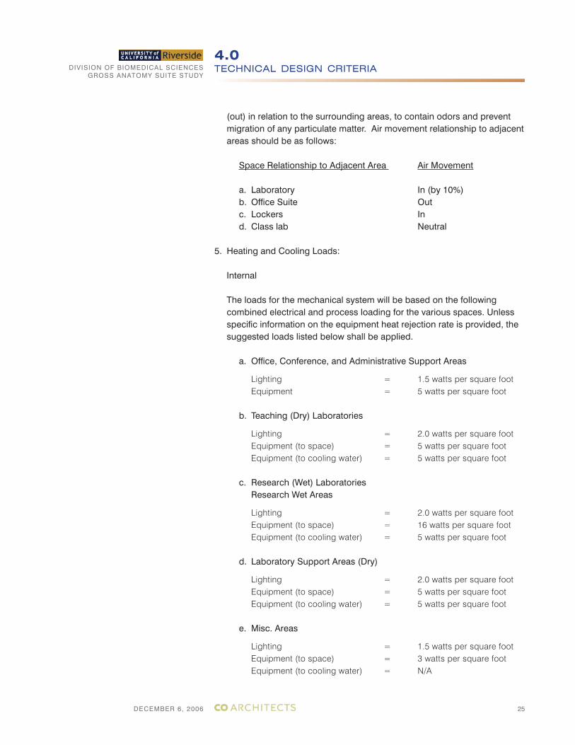
(out) in relation to the surrounding areas, to contain odors and prevent migration of any particulate matter. Air movement relationship to adjacent areas should be as follows:
Space Relationship to Adjacent Area Air Movement
a. Laboratory In (by 10%)b. Office Suite Outc. Lockers Ind. Class lab Neutral
5. Heating and Cooling Loads:
Internal
The loads for the mechanical system will be based on the following combined electrical and process loading for the various spaces. Unless specific information on the equipment heat rejection rate is provided, the suggested loads listed below shall be applied.
a. Office, Conference, and Administrative Support Areas
Lighting = 1.5 watts per square footEquipment = 5 watts per square foot
b. Teaching (Dry) Laboratories
Lighting = 2.0 watts per square footEquipment (to space) = 5 watts per square footEquipment (to cooling water) = 5 watts per square foot
c. Research (Wet) Laboratories Research Wet Areas
Lighting = 2.0 watts per square footEquipment (to space) = 16 watts per square footEquipment (to cooling water) = 5 watts per square foot
d. Laboratory Support Areas (Dry)
Lighting = 2.0 watts per square footEquipment (to space) = 5 watts per square footEquipment (to cooling water) = 5 watts per square foot
e. Misc. Areas
Lighting = 1.5 watts per square footEquipment (to space) = 3 watts per square footEquipment (to cooling water) = N/A
DIVISION OF BIOMEDICAL SCIENCESGROSS ANATOMY SUITE STUDY
DECEMBER 6, 2006
TECHNICAL DESIGN CRITERIA4.0
26
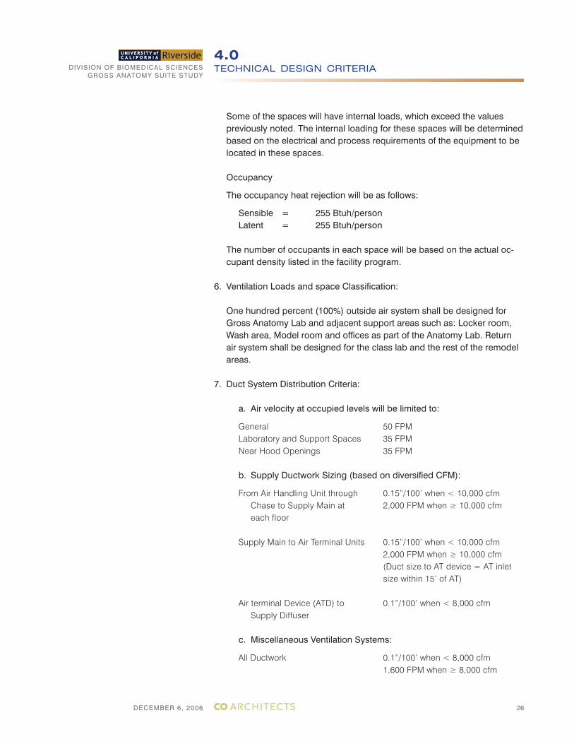
Some of the spaces will have internal loads, which exceed the values previously noted. The internal loading for these spaces will be determined based on the electrical and process requirements of the equipment to be located in these spaces.
Occupancy
The occupancy heat rejection will be as follows:
Sensible = 255 Btuh/personLatent = 255 Btuh/person
The number of occupants in each space will be based on the actual oc-cupant density listed in the facility program.
6. Ventilation Loads and space Classification:
One hundred percent (100%) outside air system shall be designed for Gross Anatomy Lab and adjacent support areas such as: Locker room, Wash area, Model room and offices as part of the Anatomy Lab. Return air system shall be designed for the class lab and the rest of the remodel areas.
7. Duct System Distribution Criteria:
a. Air velocity at occupied levels will be limited to:
General 50 FPMLaboratory and Support Spaces 35 FPMNear Hood Openings 35 FPM
b. Supply Ductwork Sizing (based on diversified CFM):
From Air Handling Unit through 0.15”/100’ when < 10,000 cfmChase to Supply Main at 2,000 FPM when ≥ 10,000 cfmeach floor
Supply Main to Air Terminal Units 0.15”/100’ when < 10,000 cfm 2,000 FPM when ≥ 10,000 cfm (Duct size to AT device = AT inlet
size within 15’ of AT) Air terminal Device (ATD) to 0.1”/100’ when < 8,000 cfm
Supply Diffuser
c. Miscellaneous Ventilation Systems:
All Ductwork 0.1”/100’ when < 8,000 cfm 1,600 FPM when ≥ 8,000 cfm
DIVISION OF BIOMEDICAL SCIENCESGROSS ANATOMY SUITE STUDY
DECEMBER 6, 2006
TECHNICAL DESIGN CRITERIA4.0
27
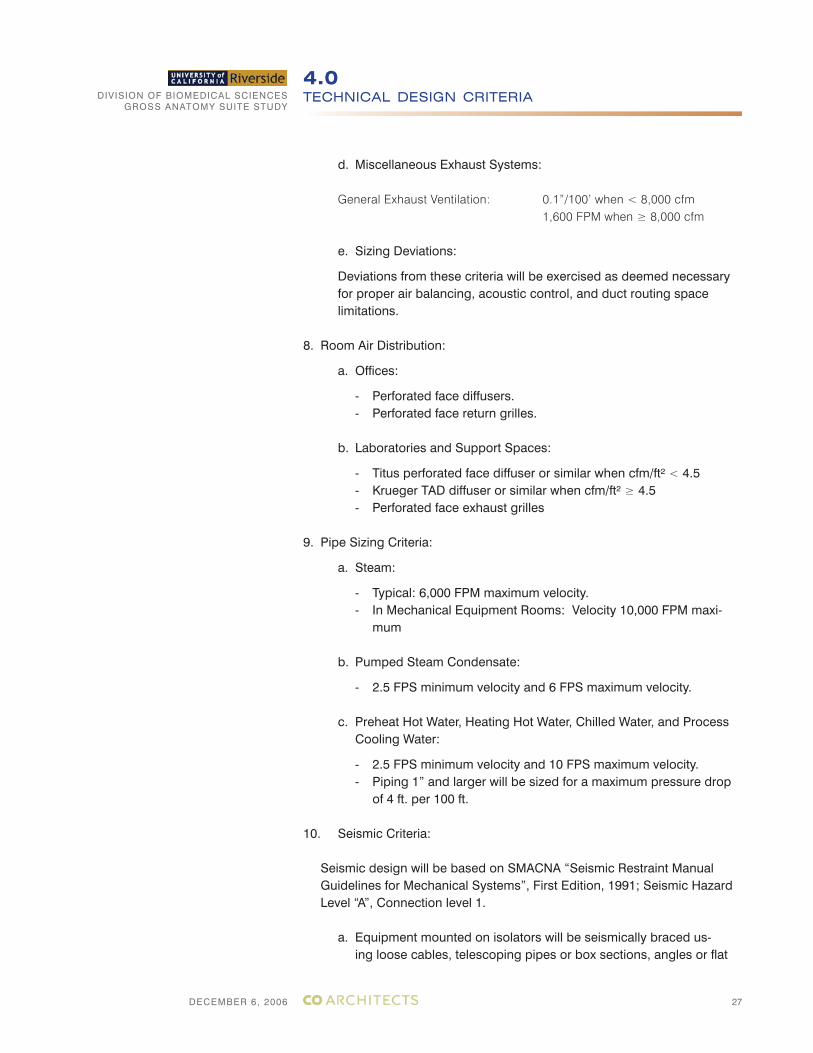
d. Miscellaneous Exhaust Systems:
General Exhaust Ventilation: 0.1”/100’ when < 8,000 cfm 1,600 FPM when ≥ 8,000 cfm
e. Sizing Deviations:
Deviations from these criteria will be exercised as deemed necessary for proper air balancing, acoustic control, and duct routing space limitations.
8. Room Air Distribution:
a. Offices:
- Perforated face diffusers.- Perforated face return grilles.
b. Laboratories and Support Spaces:
- Titus perforated face diffuser or similar when cfm/ft² < 4.5- Krueger TAD diffuser or similar when cfm/ft² ≥ 4.5- Perforated face exhaust grilles
9. Pipe Sizing Criteria:
a. Steam:
- Typical: 6,000 FPM maximum velocity. - In Mechanical Equipment Rooms: Velocity 10,000 FPM maxi-
mum
b. Pumped Steam Condensate:
- 2.5 FPS minimum velocity and 6 FPS maximum velocity.
c. Preheat Hot Water, Heating Hot Water, Chilled Water, and Process Cooling Water:
- 2.5 FPS minimum velocity and 10 FPS maximum velocity.- Piping 1” and larger will be sized for a maximum pressure drop of 4 ft. per 100 ft.
10. Seismic Criteria:
Seismic design will be based on SMACNA “Seismic Restraint Manual Guidelines for Mechanical Systems”, First Edition, 1991; Seismic Hazard Level “A”, Connection level 1.
a. Equipment mounted on isolators will be seismically braced us-ing loose cables, telescoping pipes or box sections, angles or flat
DIVISION OF BIOMEDICAL SCIENCESGROSS ANATOMY SUITE STUDY
DECEMBER 6, 2006
TECHNICAL DESIGN CRITERIA4.0
28
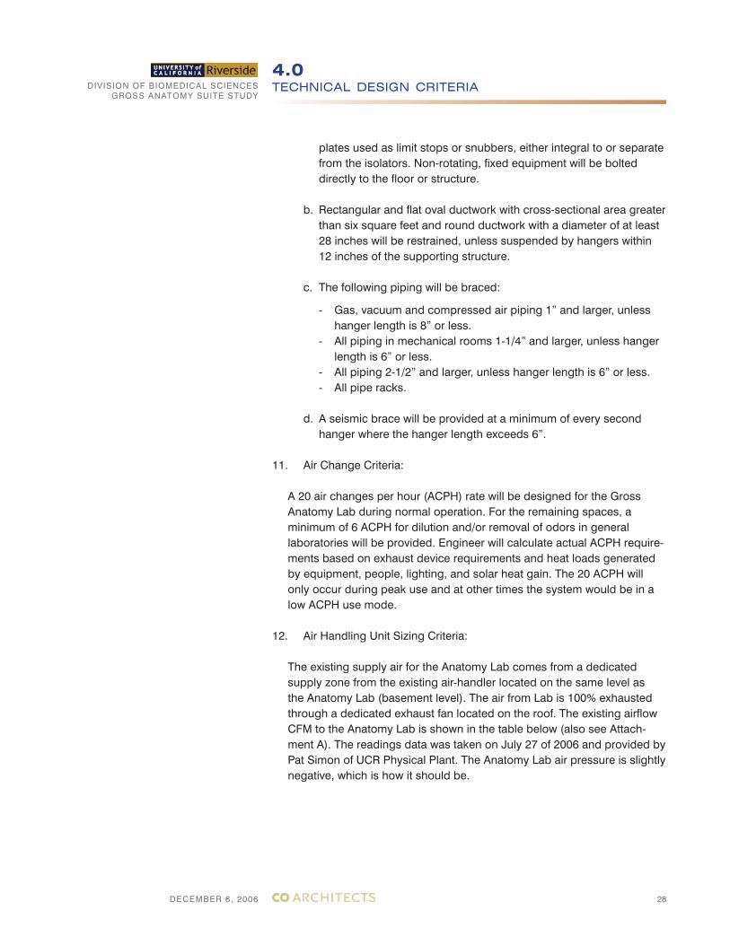
plates used as limit stops or snubbers, either integral to or separate from the isolators. Non-rotating, fixed equipment will be bolted directly to the floor or structure.
b. Rectangular and flat oval ductwork with cross-sectional area greater than six square feet and round ductwork with a diameter of at least 28 inches will be restrained, unless suspended by hangers within 12 inches of the supporting structure.
c. The following piping will be braced:
- Gas, vacuum and compressed air piping 1” and larger, unless hanger length is 8” or less.
- All piping in mechanical rooms 1-1/4” and larger, unless hanger length is 6” or less.
- All piping 2-1/2” and larger, unless hanger length is 6” or less. - All pipe racks.
d. A seismic brace will be provided at a minimum of every second hanger where the hanger length exceeds 6”.
11. Air Change Criteria:
A 20 air changes per hour (ACPH) rate will be designed for the Gross Anatomy Lab during normal operation. For the remaining spaces, a minimum of 6 ACPH for dilution and/or removal of odors in general laboratories will be provided. Engineer will calculate actual ACPH require-ments based on exhaust device requirements and heat loads generated by equipment, people, lighting, and solar heat gain. The 20 ACPH will only occur during peak use and at other times the system would be in a low ACPH use mode.
12. Air Handling Unit Sizing Criteria:
The existing supply air for the Anatomy Lab comes from a dedicated supply zone from the existing air-handler located on the same level as the Anatomy Lab (basement level). The air from Lab is 100% exhausted through a dedicated exhaust fan located on the roof. The existing airflow CFM to the Anatomy Lab is shown in the table below (also see Attach-ment A). The readings data was taken on July 27 of 2006 and provided by Pat Simon of UCR Physical Plant. The Anatomy Lab air pressure is slightly negative, which is how it should be.

DIVISION OF BIOMEDICAL SCIENCESGROSS ANATOMY SUITE STUDY
DECEMBER 6, 2006
TECHNICAL DESIGN CRITERIA4.0
29
ANATOMY LAB AIRFLOW
Grille #
SUPPLY
(CFM)
EXHAUST
(CFM)
1 810 986
2 701 619
3 785 690
4 798 1023
TOTAL 3,094 3,318
Air Change/ Hour 18.23 19.55
The existing Anatomy Lab is about 1,132 square feet (SF) and with a 9 feet ceiling, the total volume is calculated at 10,185 cubic feet. The total room air change per hour (ACH) calculations for both supply and exhaust are as follows:
Supply ACH = (3,094 x 60) / 10,185 = 18.23 Exhaust ACH = (3,318 x 60) / 10,185 = 19.55
13. Exhaust Criteria:
Dedicated Systems
Dedicated exhaust system is existing and the unit is of adequate size and will be re-used. Following spaces will covered:
1. Gross Anatomy Laboratory2. Wash Area and Locker Room3. Model room and Offices connect to Gross Anatomy Lab
There will be total of 10 low exhaust (5 along each wall).
4.1.3 REDUNDANCY
No redundancy shall be provided for new mechanical system serving the remodel area.
4.1.4 MECHANICAL SYSTEM DESCRIPTION
1. Chilled Water System
Chilled water temperature available from the central plant is 38°F to 42°F. However, 46°F will be utilized for design. The minimum return water delta T should be 20°F, with 60°F being the preferred return water temperature.
Existing Chilled water system will be re-used.
DIVISION OF BIOMEDICAL SCIENCESGROSS ANATOMY SUITE STUDY
DECEMBER 6, 2006
TECHNICAL DESIGN CRITERIA4.0
30
2. Steam/Heating/Reheat/Process Systems
Similar to chilled water, low pressured steam and pumped steam conden-sate piping are existing and will be re-used.
Heating hot water piping is also available for tie-in within mechanical room for space heating.
3. Lab Exhaust System
Existing roof mounted exhaust fan system will be reused for exhausting the Gross Anatomy lab areas. The exhaust fan shall be interlocked with air handler unit.
4. Humidification
Available low pressure steam within mechanical room will be used for humidification via steam grid, direct injection, and duct-mounted humidi-fier type.
5. Air Handling Systems
Gross Anatomy Lab and support areas:
The existing air handler unit will be re-used to serve the Gross Anatomy Lab and its support areas. See attached sketch M-1.
The new supply distribution system will consist of high-pressure, external-ly insulated galvanized steel ductwork with pressure independent electri-cally actuated supply CAV air terminal devices, reheat coils, low pressure externally insulated ductwork downstream of air terminals, and diffusers. Sound attenuating flexible ductwork with woven nylon fabric type lining will be provided at the supply diffusers to control noise.
Ductwork will be constructed in accordance with SMACNA standards and duct leakage shall not exceed 1% of the design volumetric flow rate for high-pressure ductwork and 2% for low-pressure ductwork. The use of sound attenuating flexible duct at diffusers and grilles will be limited to seven feet in total length to minimize duct static pressure losses.
Supply air will be distributed to the Gross Anatomy Lab is as follows: Laminar airflow type of diffuser shall be installed directly above each working bench. Room air will be exhausted out via sidewall low exhaust grilles as shown in sketch M-3.
The existing roof mounted exhaust fan will be re-used to exhaust all air from Gross Anatomy Lab to outside. The exhaust fan shall be interlocked with existing air handler unit. See attached sketch M-1.
DIVISION OF BIOMEDICAL SCIENCESGROSS ANATOMY SUITE STUDY
DECEMBER 6, 2006
TECHNICAL DESIGN CRITERIA4.0
31
Class lab:
At the present, the class lab is served by an existing AH unit located in the adjacent mechanical room #1. The existing AH unit has supply and return air distribution ductwork. The operating condition of existing AH system is in excellent working condition. Existing supply and return air ductwork will be re-arranged to provide air conditioning to the class lab for the remodel project. At the minimum, the class lab will receive 6 air changes of air per hour. Final sizing airflow amount can be determined during the construc-tion design document phase. See attached sketch M-3.
6. Controls System
a. The existing control system for the air handling unit and exhaust fan will be re-used.
b. Existing controls system for the Classroom remodel project shall be reused and reconnected to existing controls system.
7. Add Alternate No. 1 Air Distribution System for 300 CFM Down Draft Table
In this add alternate the dissecting table will be replaced with down draft table. Each down draft table will be sized for 300 CFM exhaust. Both the existing air-handling unit and existing exhaust fan will be re-used. The supply side will be designed as described above. For the exhaust system instead of low exhaust the exhaust duct will come down and make a hard connection to each of the down draft table.
8. Other Requirements
• All control devices shall be accessible for service and inspection.• Balancing valves shall be in addition to isolation valves and not used for both purpose.• Air flow monitor shall be provided for VAV boxes controlled by the EMS.• Provide electronic actuators for all control valves and control dampers.• A commissioning team other than the design team shall be engaged to complete startup and commissioning.
DIVISION OF BIOMEDICAL SCIENCESGROSS ANATOMY SUITE STUDY
DECEMBER 6, 2006
TECHNICAL DESIGN CRITERIA4.0
32
4.2 ELECTRICAL SYSTEMS
4.2.1 GENERAL
The requirement for the Electrical and Communication systems for this project are to provide a safe and comfortable and efficient work environ-ment for the occupants while being energy efficient and deferring any major maintenance and meet the programmatic needs of the user.
The lighting, power, security, fire alarm and telephone data requirements for the new Gross Anatomy and Class lab will be upgraded from the exist-ing system.
The existing electrical system infrastructure has adequate capacity and will be re-used.
4.2.2 EXISTING ELECTRICAL SYSTEMS
• Normal primary power service at 4.16kV is provided from UCR Campus distribution to two unit substation and distributed to the buildings at 480/277V, and 208/120V, 3 phase, 4 wire, 60 Hz. throughout the building via network of switchboards, distribution panel boards and branch circuit panel boards.
The unit substation consists:CHHV: 1-500kVA, 4.16kV/480-277V, 600A Bus.CLHV: 1-500kVA 4.16kV/208-120V, 1600A Bus. There is adequate capacity to meet the needs of the Improvement
Project.
• Portable Standby Power: Diesel generator located outdoor pro-vides emergency power for operation during utility power outage.
• Lighting – Interior lighting consists of mostly 2x4 fluorescent-lensed fixture in the existing Gross Anatomy Lab and Class lab. In addition to the 2x4 class lab have round incandescent down lights on dim-mers. In addition to the 2x4 the gross anatomy lab have pendant surgical lights over each dissecting table.The fixtures are in poor condition and will require replacement.
• There is an existing Fire Alarm System but the system in the gross anatomy lab and class lab will require to be upgraded to meet cur-rent codes and DSA requirements.
• Telephone/Data Cabling System. The existing system will be utilized for additional voice and data outlet for the gross anatomy lab and class lab.
• There is no existing security system.
DIVISION OF BIOMEDICAL SCIENCESGROSS ANATOMY SUITE STUDY
DECEMBER 6, 2006
TECHNICAL DESIGN CRITERIA4.0
33
4.2.3 CODES AND STANDARDS
The project shall meet the requirements of all applicable codes and shall include but not be limited to the code section references listed below:
• 2002 National Electric Code • National Fire Protection Association (NFPA).• National Electrical Manufacturer’s Association (NEMA).• Underwriters’ Laboratories (UL).• Occupational Safety and Health Act (OSHA).• State of California - Cal OSHA.• 2003 California Building Code• 2004 California Electrical Code • California Title 24.• UCR Physical Plant Building Standards.
The standards listed below are intended as guidelines for design only. The list is not meant to restrict engineers from using additional guides or standards as desired.
• Electronic Industries Application (EIA) Standard 569.• Illuminating Engineering Society of North America (IES) Lighting Stan-
dards. • Institute of Electrical and Electronic Engineers (IEEE) Standards. • Federal Information Processing Standard 5-91. • National Electrical Manufacturers’ Association (NEMA). • Insulated Power Cable Engineers’ Association (IPCEA). • Certified Ballast Manufacturers’ Association (CBMA). • Underwriters Laboratories, Inc. (UL). • National Fire Protection Association (NFPA). • Rules and regulations of local utility companies.• UCR Campus Standards.• EIA/TIA
4.2.4 ELECTRICAL DESIGN CRITERIA
1. Energy Conservation:
a) One of the factors in the energy consumption of a building is light-ing. A good control strategy, which eliminates lighting in unoc-cupied spaces and reduces it where day lighting is available, will contribute to energy conservation to a considerable degree. The way to institute such controls is through a combination of Low Volt-age Lighting Control System, Occupancy Sensors. See Section on Lighting for further details.
DIVISION OF BIOMEDICAL SCIENCESGROSS ANATOMY SUITE STUDY
DECEMBER 6, 2006
TECHNICAL DESIGN CRITERIA4.0
34
b) All motors will be of high efficiency or better, especially for air han-dlers.
c) Energy efficiency design shall be implemented into the project. Computer modeling shall incorporate State of California Title 24 re-quirements and include both mechanical and electrical power use.
2. System Voltages:
a) A 480/277V distribution system will be used for all major power and lighting loads. Other voltages will be used where size and econ-omy dictate, such as, 208V and 120V for labs, office and conve-nience outlet.
4.2.5 ELECTRICAL LOAD AND SYSTEM DESCRIPTION
In establishing electrical loads for the new and improved Gross Anatomy Lab and Class lab, Consulting Solutions will look beyond the immediate requirements stated in the project program. The minimum connected load of 25 watts per square feet, which includes other building loads (such as lab facility) multiplied by appropriate demand factors will be used for obtaining the overall electrical load of the TI Project. Power connection to the air handling unit and exhaust fan will remain.
Watts per square foot includes connected load for HVAC system, plumb-ing system, lab equipment, office equipment, lighting, general outlets, controls, alarm system, Tel/Data system and security system.
1. Electrical Load Calculation Criteria
Administration/Office/Open Workstations Lighting 1.3 VA/sf Receptacles 5.0 VA/sf
Class labs Lighting 1.6VA/sf Receptacles 5.0VA/sf
Gross Anatomy Lab Lighting 1.6VA/sf Power 20.0VA/sf
Mechanical/Plumbing Equipment Power Actual equipment load
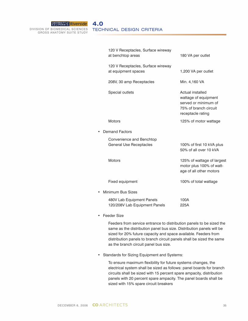
2. Equipment Sizing Criteria
• Branch Circuit Load Calculations
Receptacles 180 VA per outlet
DIVISION OF BIOMEDICAL SCIENCESGROSS ANATOMY SUITE STUDY
DECEMBER 6, 2006
TECHNICAL DESIGN CRITERIA4.0
35
120 V Receptacles, Surface wireway at benchtop areas 180 VA per outlet
120 V Receptacles, Surface wireway at equipment spaces 1,200 VA per outlet
208V, 30 amp Receptacles Min. 4,160 VA
Special outlets Actual installed wattage of equipment served or minimum of 75% of branch circuit receptacle rating
Motors 125% of motor wattage
• Demand Factors
Convenience and Benchtop General Use Receptacles 100% of first 10 kVA plus 50% of all over 10 kVA
Motors 125% of wattage of largest motor plus 100% of watt- age of all other motors
Fixed equipment 100% of total wattage
• Minimum Bus Sizes
480V Lab Equipment Panels 100A 120/208V Lab Equipment Panels 225A
• Feeder Size
Feeders from service entrance to distribution panels to be sized the same as the distribution panel bus size. Distribution panels will be sized for 20% future capacity and space available. Feeders from distribution panels to branch circuit panels shall be sized the same as the branch circuit panel bus size.
• Standards for Sizing Equipment and Systems:
To ensure maximum flexibility for future systems changes, the electrical system shall be sized as follows: panel boards for branch circuits shall be sized with 15 percent spare ampacity, distribution panels with 20 percent spare ampacity. The panel boards shall be sized with 15% spare circuit breakers
DIVISION OF BIOMEDICAL SCIENCESGROSS ANATOMY SUITE STUDY
DECEMBER 6, 2006
TECHNICAL DESIGN CRITERIA4.0
36
• Load Study and Short Circuit Calculation.
SKM Software will be used to develop a Demand Load Study, Load Flow and Voltage Drop Study, Short Circuit Fault Study.
4.2.6 NEW ELECTRICAL SYSTEM DESCRIPTION
1. Distribution System:
• Layout of Conduit: All branch circuits and feeders will be in con-duits.
• Conductors: All conductors will be copper, THWN, 600Volt insula-tion. Conductor that is installed in underground duct banks will have XHHW type insulation.
• Receptacle Panelboards: Receptacle panelboards will be circuit breaker type. The neutral for receptacle panels shall be sized to 200% of line bus. All 208/120V panelboard shall be provided with hinged lockable wireway covers and hinged lockable circuit breaker covers. There will be one new panel for the Gross Anatomy Lab and one for the Class Lab. All panelboards will be recessed in lab walls.
• Lighting panel board exists and will be re-used. 2. Electrical Identification
The identification system will consist of plastic laminate (white lettering on red field for emergency and white lettering on black field for normal) and will be installed for each unit of following categories of equipment using mechanical fasteners:
• Panelboards, electrical cabinets and enclosures.• Disconnect switches.• Enclosed circuit breakers.• Fire Alarm Panel.• Security System Panel.• Tel/Data System Equipment
Wall plates for receptacles and light switches will be identified with panel-board and circuit number from which served.
3. Grounding System
All parts of the power distribution system will be provided with an equip-ment ground conductor. This system will extend from the building service
DIVISION OF BIOMEDICAL SCIENCESGROSS ANATOMY SUITE STUDY
DECEMBER 6, 2006
TECHNICAL DESIGN CRITERIA4.0
37
transformer to the branch circuit load or device. All branch circuit and feeder conduit will be provided with a green ground conductor sized per NEC.
4. Interior Lighting
Lighting will be designed to enhance both the overall building architecture as well as the effect of individual spaces within the building. All lighting fixtures will be suitable for operation at 277 VAC except for incandescent which will be suitable for operation at 120 volt.
Interior Lighting: Consideration will be given to the options by direct lighting, indirect lighting, down lighting, up lighting, and lighting from wall-mounted fixtures.
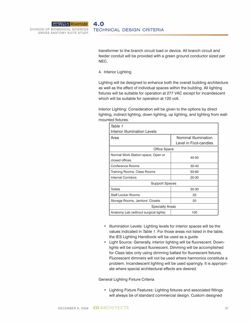
• Illumination Levels: Lighting levels for interior spaces will be the values indicated in Table 1. For those areas not listed in the table, the IES Lighting Handbook will be used as a guide.
• Light Source: Generally, interior lighting will be fluorescent. Down-lights will be compact fluorescent. Dimming will be accomplished for Class labs only using dimming ballast for fluorescent fixtures. Fluorescent dimmers will not be used where harmonics constitute a problem. Incandescent lighting will be used sparingly. It is appropri-ate where special architectural effects are desired.
General Lighting Fixture Criteria
• Lighting Fixture Features: Lighting fixtures and associated fittings will always be of standard commercial design. Custom designed
Table 1Interior Illumination Levels
Area Nominal IlluminationLevel in Foot-candles
Office Space
Normal Work Station space, Open or
closed offices45-50
Conference Rooms 30-40
Training Rooms, Class Rooms 50-60
Internal Corridors 20-30
Support Spaces
Toilets 20-30
Staff Locker Rooms 20
Storage Rooms, Janitors’ Closets 20
Specialty Areas
Anatomy Lab (without surgical lights) 100
DIVISION OF BIOMEDICAL SCIENCESGROSS ANATOMY SUITE STUDY
DECEMBER 6, 2006
TECHNICAL DESIGN CRITERIA4.0
38
fixtures will be avoided. They will be used with express approval from UCR in cases where available standard units cannot fulfill the required function.
• Lighting fixtures will be clearly described in a fixture schedule, including the method of mounting and means of control. Louvered parabolic fixtures or indirect fixtures are recommended in all envi-ronments where use of PC terminals are anticipated. Indirect light-ing will be used in all open lab and office areas. Lighting fixture in the storage area will be an acrylic-lenses fluorescent fixture. When acrylic fluorescent fixtures are used, lenses will be acrylic prismatic and nominal 0.125 inches thick.
• Lamps and Ballasts: In general, fluorescent lamps will be T-8 3500 degree Kelvin. T-5 lamps may be utilized for direct/indirect fixtures where approved by the architect and owner. Ballast will be electron-ic type.
a. Lighting Criteria for Building Spaces
• Lab and Office Lighting: Linear direct/Indirect lighting will be used in open lab and office space. A uniform lighting layout with an even level of illuminations will be designed because it will facilitate rearrangement of office areas with minimal fixture relocation. Task lighting will also be provided at each bench top.
• Gross Anatomy and Support Areas: 2’x4’, 4 lamp fluorescent trof-fers with acrylic lens. Gross Anatomy Lab will be provided with triple gasketed light fixture.
In addition to 2x4 fluorescent fixture Gross Anatomy Lab will be provided with surgical lights over each dissecting table. These will be individually controlled.
• Conference Rooms: These spaces will have a combination of fluo-rescent and dimmable compact fluorescent.
• Egress and Exit Lighting: Egress and exit lighting will be designed to comply with NFPA 101. Exit lights shall be edge lit green LED.
b. Lighting Controls
All lighting will be provided with manual, automatic, or programma-ble lighting controls. The application of these controls and the con-trolled zones will depend on a number of space factors: frequency of use; normal and extended work hours; office plans closed or open. All of these factors will be considered when establishing zones, zone controls and appropriate lighting control. All lighting
DIVISION OF BIOMEDICAL SCIENCESGROSS ANATOMY SUITE STUDY
DECEMBER 6, 2006
TECHNICAL DESIGN CRITERIA4.0
39
controls will meet the California Title 24 requirements. The lighting control will be addressable low voltage system. The Watt Stopper or Square D system will be used.
• All lighting fixtures shall be made in the United States and stocked in Southern California
• Occupancy sensor control of lighting in all conference rooms, bathrooms, assembly rooms.
• Exit signs will be low wattage fixture.
DIVISION OF BIOMEDICAL SCIENCESGROSS ANATOMY SUITE STUDY
DECEMBER 6, 2006
TECHNICAL DESIGN CRITERIA4.0
40
4.3 PLUMBING SYSTEMS
4.3.1 GENERAL
Systems will be designed in accordance with listed applicable Codes, Standards and Authorities having jurisdiction, the Underwriters’ and in accordance with current engineering practices.
Utilities shall be provided from the existing building services.
Codes and Standards
The installation shall comply with all applicable codes and standards such as:
• California Plumbing Code (CPC) 2001 Edition.• California Building Code (CBC) 2001 Edition.• California Administrative Code:• Title 8: General Industry Safety Order• Title 17: Public Health• Title 24: Building Standards• Americans with Disabilities Act (A.D.A.)• ANSI -American National Standards Institute• UL - Underwriters’ Laboratories• AGA - American Gas Association• ASME - American Society of Mechanical Engineers• ASSE - American Society of Sanitary Engineers• ASTM - American Society for Testing and Materials• AWWA - American Water Works Association• NSF - National Sanitation Foundation• PDI - Plumbing and Drainage Institute• National Fire Protection Association:• NFPA 13 Installation of Sprinkler Systems• NFPA 45 Fire Protection in Laboratories using Chemicals• NFPA 54 National Fuel Gas Code• UCR Physical Plant Building Standards.
All other Local and State codes and University of California Riverside stan-dards will be adhered to where applicable and available.
4.3.2 DOMESTIC HOT & COLD WATER (POTABLE)
Potable hot and cold water will be provided for all emergency eyewash units, and all other fixtures and devices that require a potable water supply.
DIVISION OF BIOMEDICAL SCIENCESGROSS ANATOMY SUITE STUDY
DECEMBER 6, 2006
TECHNICAL DESIGN CRITERIA4.0
41
The potable hot and cold-water distribution piping will be sized for a maximum velocity of 6 FPS. Water conservation faucets and fixtures will be utilized to meet and/or exceed required code minimums.
The cold water line, will supply water to the emergency eyewash fixtures. This line will be monitored by an in-line flow sensor, that in turn is con-nected to an electric alarm gong and building security system for 24 hour observation or to other location(s) as directed by the University Represen-tative.
The domestic hot and cold water systems shall be Type L copper tubing with wrought copper fittings and lead free soldered joints.
All potable hot water piping will be insulated.
All domestic hot and cold water shall be in compliance with UCR guide-lines and codes.
4.3.3 SANITARY WASTE
A sanitary waste and vent system will be provided for sanitary waste producing fixtures and equipment. All fixtures will be individually trapped and vented.
The sanitary sewer system will flow by gravity.
Sanitary waste and vent piping above ground will be service weight hubless cast iron pipe. Couplings for above ground shall be approved stainless steel couplings. The sanitary waste and vent system shall be in compliance with UC River-side guidelines and codes.
4.3.4 INSULATION
All piping, components, and equipment subject to sweating, heat loss or freezing will be in accordance with State Energy Code with appropriate thickness of insulation.
4.3.5 SEISMIC RESTRAINTS
1. Piping and components will be provided with restraints and anchorage consistent with the seismic zone.
4.3.6 PLUMBING FIXTURES
1. Fixtures will be provided with chromium-plated brass trim and individual stop valves.
DIVISION OF BIOMEDICAL SCIENCESGROSS ANATOMY SUITE STUDY
DECEMBER 6, 2006
TECHNICAL DESIGN CRITERIA4.0
42
2. Emergency eye washers will be provided as required.
3. Sinks and other equipment supplied will be provided with all trim items including combination supply fixtures and traps.
4. Floor drains for general use will be provided with removable gratings and trap primers.
4.3.7 FIRE PROTECTION
All areas of the remodel area will be fully sprinklered by an existing au-tomatic wet sprinkler system. Revise existing piping and sprinkler heads based on Ordinary Hazard, Group II, with a maximum sprinkler head spacing of 130 square feet.
4.3.8 OTHER REQUIREMENTS
• All isolation valves, control valves and strainers shall be accessible.• All restrooms shall be equipped with floor drains.• All restroom floors shall be sloped to drain to the floor drain.• Sloan flush valve are the campus standard and shall be provided. Any substitution must be approved by the Physical Plant.• The connection of condensation indirect waste lines to direct waste lines will be in mechanical rooms and must be accessible.• Provide color coded labeling on all piping that will show: type of fluid in pipe, direction of flow, system served.
DIVISION OF BIOMEDICAL SCIENCESGROSS ANATOMY SUITE STUDY
DECEMBER 6, 2006
TECHNICAL DESIGN CRITERIA4.0
43
4.4 FIRE ALARM SYSTEM
The fire alarm system exists and will be upgraded to bring the class lab and gross anatomy lab to code standard. This will include addition of smoke detectors and horn/strobe in the class lab and gross anatomy lab. The fire alarm system shall be Simplex where their price is equal. Price determination should include the initial installed cost plus warranty cost and maintenance cost for the first five years of operation. Physical Plant will receive submittals for review prior to acceptance.
4.5 SIGNAL/COMMUNICATION
The telephone/data system will consists of wall outlets with RJ45 jacks and faceplate in all occupied spaces such as office, gross anatomy lab, class lab. These station outlets will be connected to existing data rack in IDF room via conduit. All telephone/data cabling will be designed.
4.6 SECURITY
The security system will consist of card access system and CCTV surveil-lance system. All equipment and wiring will be designed.
Card access and CCTV camera will be provided at entrances to Gross Anatomy Lab Suite.
4.7 A/V TECHNOLOGY
The design of the renovation will include the complete integration of a comprehensive network of pathways for audio/visual and information technology. A cable raceway, connecting the Class lab with the Gross Anatomy suite, is recommended to facilitate the integration of the au-dio/visual network between the two spaces. Audio visual projectors and manual screens will be provided in instructional spaces. Data connections will be available in class labs, teaching labs, and offices.
DIVISION OF BIOMEDICAL SCIENCESGROSS ANATOMY SUITE STUDY
DECEMBER 6, 2006
TECHNICAL DESIGN CRITERIA4.0
44
4.8 APPLICABLE CODES AND REGULATIONS
The following Codes and Standards are provided for general reference as the basis for the study. At the time of design, the most recently adopted versions of all applicable codes as well as the then-current University standards will need to be utilized as the basis for design. The design team will need to make the final determination as to the relevance and applica-tion of these codes as well as others that may apply but not be included in the list below.
Building Codes• California Building Standards Code, Title 24 of the California Code of
Regulations. 2001 Edition• Uniform Building Code, 1997 edition, and 1998 California Amendments• Uniform Building Code Standards, 1997 edition• Uniform Mechanical Code, 1998 edition, and 1998 California
Amendments• Uniform Plumbing Code, 1998 edition, and 1998 California
Amendments• Uniform Fire Code, 2000 edition• National Electric Code, 1999 edition, and 1998 California Amendments• California Code of Regulations, California Administrative Code Title 24,
1998 edition• California Code of Regulations, Title 8, Industrial Relations• California Code of Regulations, Title 19 - Public Safety• California Code of Regulations, Title 21 - Public Works• California Health and Safety Code, current regulations• California Administrative Code Title 8 - Industrial Relations• California Administrative Code Title 19 - Public Safety• State of California Fire Code, 2001 Edition• NFPA 10, National Fire Protection Association Standard for Portable
Fire Extinguishers, 2000 edition • NFPA 13, National Fire Protection Association Installation of Sprinkler
Systems, 2000 edition• NFPA 14, National Fire Protection Association Installation of Standpipe
and Hose systems, 2000 edition• NFPA 24, National Fire Protection Association Installation of Private
Fire Service Mains and Their Apparatus, 1995 edition• NFPA 30, National Fire Protection Association Flammable and
Combustible Liquids Code, 2000 edition• NFPA 45, National Fire Protection Association Standard on Fire
Protection for Laboratories Using Chemicals, 2000 edition• NFPA 72, National Fire Protection Association National Fire Alarm
Code, 1993 edition• NFPA 101, National Fire Protection Association Code for Safety to Life
from Fire in Buildings and Structures, 2000 edition
DIVISION OF BIOMEDICAL SCIENCESGROSS ANATOMY SUITE STUDY
DECEMBER 6, 2006
TECHNICAL DESIGN CRITERIA4.0
45
Reference Standards and Regulations• University of California, Riverside Campus Standards and
Design Criteria.• Americans with Disabilities Act (ADA), 1991, Title 3 and
ADA P.L. 101-336• Federal Standard 29 CFR Part 1910.1450 Occupational exposures to
hazardous chemicals in laboratories• American National Standards Institute 2358.1: Emergency Eyewash
and Shower Equipment, 1990• American National Standards Institute/American Industrial Hygienists
Association 29.5 Standard for Laboratory Ventilation, 1992• National Institutes of Health NIH 76-900 Safety Standards for Research
Involving Chemical Carcinogens, Office of Research Safety• National Institutes of Health NIH 81-2385 Guidelines for the Laboratory
Use of Chemical Carcinogens, 1981• Cast Iron Soil Pipe Institute (CISPI)• Manufacturers Standardization Society (MSS)• National Bureau of Standards• Plumbing & Drainage Institute (PDI)• South Coast Air Quality Management District (SCAQMD)• Underwriters Laboratory (U.L.)• Illuminating Engineering Society of North America (IES)• Sheet Metal and Air Conditioning Contractors National Affiliation
(SMACMA)• Institute of Electrical & Electronics Engineers (IEEE)• National Electrical Manufacturers Affiliation (NEMA)• Occupational Safety and Health Administration (OSHA)• American National Standards Institute (ANSI)• American Society of Testing Materials (ASTM)• American Welding Society Code (AWSC)• American Society of Heating, Refrigerating and Air Conditioning
Engineers (ASHRAE)• Standard 62• Standard 90 A, B, C Energy Conservation in New Building Design• Standard 100 Energy Conservation in Existing Buildings• ASHRAE Fundamentals• ASHRAE Systems and Applications• ASHRAE Equipment
All of the above codes, standards and requirements should be reviewed as to the currently adopted version at the time of the design.
DIVISION OF BIOMEDICAL SCIENCESGROSS ANATOMY SUITE STUDY
DECEMBER 6, 2006
TECHNICAL DESIGN CRITERIA4.0
46
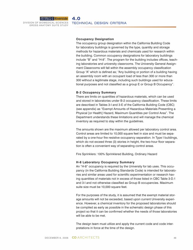
Occupancy DesignationThe occupancy group designation within the California Building Code for laboratory buildings is governed by the type, quantity and storage methods for hazardous materials and chemicals used for research within the building. Common occupancy designations for laboratory buildings include “B” and “H-8”. The program for the building includes offices, teach-ing laboratories and university classrooms. The University General Assign-ment Classrooms will fall within the assembly occupancy classification Group “A” which is defined as; “Any building or portion of a building having an assembly room with an occupant load of less than 300 or more than 300 without a legitimate stage, including such buildings used for educa-tional purposes and not classified as a group E or Group B Occupancy”.
B-2 Occupancy SummaryThere are limits on quantities of hazardous materials, which can be used and stored in laboratories under B-2 occupancy classification. These limits are described in Tables 3-I and 3-E of the California Building Code (CBC) (see appendix) as “Exempt Amounts of Hazardous Materials Presenting a Physical [or Health] Hazard, Maximum Quantities per Control Area”. The Department understands these limitations and will manage the chemical inventory as required to stay within the guidelines.
The amounts shown are the maximum allowed per laboratory control area. Control areas are limited to 10,000 square feet in size and must be sepa-rated by a one-hour fire resistive occupancy separation. In Type I buildings, which do not exceed three (3) stories in height, the two-hour floor separa-tion is often a convenient way of separating control areas.
Fire Sprinklers: 100% Sprinklered Building, Ordinary Hazard
H-8 Laboratory Occupancy SummaryAn “H-8” occupancy is required by the University for lab uses. This occu-pancy (in the California Building Standards Code) is intended for laborato-ries and similar areas used for scientific experimentation or research hav-ing quantities of materials not in excess of those listed in CBC Table 3-D.1 and 3-I and not otherwise classified as Group B occupancies. Maximum suite size must be 10,000 square feet.
For the purposes of the study, it is assumed that the exempt material stor-age amounts will not be exceeded, based upon current University experi-ence. However, a chemical inventory for the proposed laboratories should be compiled as early as possible in the schematic design phase of this project so that it can be confirmed whether the needs of those laboratories will be able to be met.
The design team must utilize and apply the current code and code inter-pretations in force at the time of the design.

DIVISION OF BIOMEDICAL SCIENCESGROSS ANATOMY SUITE STUDY
DECEMBER 6, 2006
TECHNICAL DESIGN CRITERIA4.0
47
NFPA 45: Fire Protection For Laboratories Using Chemicals
Means of Egress: The means of egress for laboratory units and labora-tory work areas shall comply with NFPA 101.
Access to Exits: A second means of access to an exit shall be pro-vided from a laboratory work area if any of the following situations exist:
i. A laboratory work area contains an explosion hazard so located that an incident would block escape from or access to the laboratory work area.
ii. A fume hood in a laboratory work area is located adjacent to the primary means of exit access.
iii. A compressed gas cylinder in use which is larger than lecture bottle size, and contains a gas which is flammable or has a hazard rat-ing of 3 or 4 and would prevent safe egress in event of accidental release of cylinder contents.
iv. The required exit doors of all laboratory work areas within Class A or Class B laboratory units shall swing in the direction of exit travel.
Furniture and Equipment: Furniture and equipment in laboratory work areas will be arranged so that means of access to an exit may be reached easily from any point.
Explosion Hazard: Explosion hazard is considered to exist if materials with a reactivity rating of 4 are stored or used, or if highly exothermic reactions or procedures without established properties are planned, or if high pressure reactions are planned.
Program information does not indicate that explosion hazards, as described above, exist in this project.
NFPA 101: Life Safety Code
Means of Egress: Where exits are not immediately accessible from an open floor area, safe and continuous passageways, aisles, or corridors will be maintained leading directly to every exit and will be arranged as to provide convenient access for each occupant to at least two exists by separate ways of travel.
Exit access will be so arranged that it will not be necessary to pass through any area identified under protection from hazards in Chapter 28.
Corridor Width: The minimum width of any corridor or passageway serv-ing as a required exit, exit access, or exit discharge will be 44 inches.
DIVISION OF BIOMEDICAL SCIENCESGROSS ANATOMY SUITE STUDY
DECEMBER 6, 2006
BUDGET AND COST ANALYSIS5.0
48
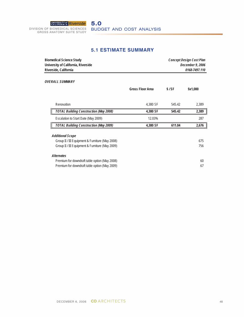
5.1 ESTIMATE SUMMARY
Biomedical Science Study Concept Design Cost PlanUniversity of California, Riverside December 9, 2006Riverside, California 0168-7497.110
OVERALL SUMMARY
Gross Floor Area $ / SF $x1,000
Renovation 4,380 SF 545.42 2,389
TOTAL Building Construction (May 2008) 4,380 SF 545.42 2,389
Escalation to Start Date (May 2009) 12.03% 287
TOTAL Building Construction (May 2009) 4,380 SF 611.04 2,676
Additional ScopeGroup II / III Equipment & Furniture (May 2008) 675Group II / III Equipment & Furniture (May 2009) 756
AlternatesPremium for downdraft table option (May 2008) 60Premium for downdraft table option (May 2009) 67
DIVISION OF BIOMEDICAL SCIENCESGROSS ANATOMY SUITE STUDY
DECEMBER 6, 2006
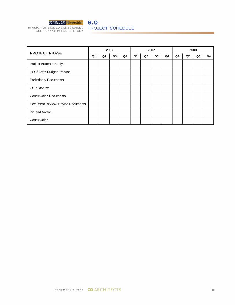
PROJECT SCHEDULE6.0
49
Q4Q3Q2Q1Q4Q3Q2Q1Q4
Project Program Study
Q3Q2Q1
20082007
Bid and Award
PPG/ State Budget Process
Preliminary Documents
Construction
PROJECT PHASE
UCR Review
Construction Documents
Document Review/ Revise Documents
2006
DECEMBER 6, 2006
DIVISION OF BIOMEDICAL SCIENCESGROSS ANATOMY SUITE STUDY
A1-1
DETAILED SPACE REQUIREMENTS AND DIAGRAMSA1.0
NOTE: DIAGRAMS ARE FOR REFERENCE ONLY
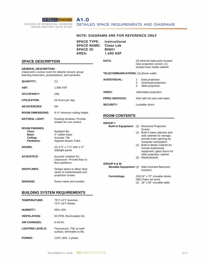
SPACE TYPE: InstructionalSPACE NAME: Class LabSPACE ID: B0601AREA: 1,590 ASF
DECEMBER 6, 2006
DIVISION OF BIOMEDICAL SCIENCESGROSS ANATOMY SUITE STUDY
A1-2
DETAILED SPACE REQUIREMENTS AND DIAGRAMSA1.0
NOTE: DIAGRAMS ARE FOR REFERENCE ONLY
SPACE TYPE: InstructionalSPACE NAME: Class LabSPACE ID: B0601AREA: 1,590 ASF
SPACE DESCRIPTION
GENERAL DESCRIPTION:Classroom/ Lecture room for didactic lecture, group learning instruction, presentations, and seminars.
QUANTITY: (1)
ASF: 1,590 ASF
OCCUPANCY: (49)
UTILIZATION: 24 hours per day.
ADJACENCIES: NA
ROOM DIMENSIONS: 9'-0" minimum ceiling height.
NATURAL LIGHT: Existing windows. Provide shades for sun control.
ROOM FINISHES: Floor: Resilient tile.
Base: 4" rubber base. Ceiling: Acoustic Tile. Partitions: Gypsum Board, Paint.
DOORS: (2) 3'-0" x 7'-0" with 1’-0” sidelight panel.
ACOUSTICS: Acoustic isolation for Classroom. Provide floor to floor partitions.
SIGHTLINES: Design space to allow clear views to markerboards and projection screen.
SIGNAGE: Room name and number.
BUILDING SYSTEM REQUIREMENTS
TEMPERATURE: 75 F ±2 F Summer,72 F ±3 F Winter
HUMIDITY: 55% ±5%
VENTILATION: 50 FPM, Recirculated Air.
AIR CHANGES: 6 AC/Hr.
LIGHTING LEVELS: Fluorescent, 75fc at work surface, dimmable to 5fc.
POWER: 110V, 60A, 1 phase.
DATA: (3) ethernet data ports located near projection screen, (1) located near media cabinet.
TELECOMMUNICATIONS: (2) phone outlet.
AUDIOVISUAL: 1. Data projection. 2. Overhead projection.
3. Slide projection.
VIDEO: Video/data projection.
PIPED SERVICES: Sink with hot and cold water.
SECURITY: Lockable doors.
ROOM CONTENTS
GROUP I: Built-in Equipment: (1) Motorized Projection
Screen(1) Built-in base cabinets and
wall cabinets for storage; provide knee opening for computer workstation.
(1) Built-in Media Cabinet for remote audiovisual equipment; glass doors for slide projection cabinet.
(2) Markerboards
GROUP II & III: Movable Equipment: (2) Wall mounted flatscreen
monitors
Furnishings: (24) 24" x 72" movable desks. (48) Chairs w/t arms (1) 18” x 60” movable table
DECEMBER 6, 2006
DIVISION OF BIOMEDICAL SCIENCESGROSS ANATOMY SUITE STUDY
A1-3
DETAILED SPACE REQUIREMENTS AND DIAGRAMSA1.0
NOTE: DIAGRAMS ARE FOR REFERENCE ONLY
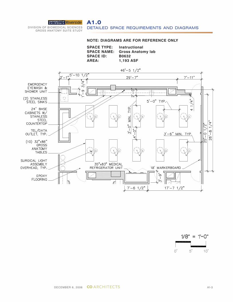
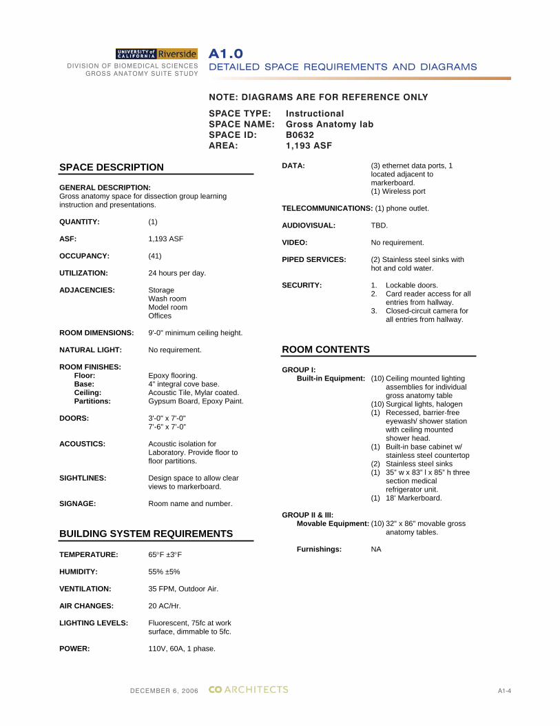
SPACE TYPE: InstructionalSPACE NAME: Gross Anatomy labSPACE ID: B0632AREA: 1,193 ASF
DECEMBER 6, 2006
DIVISION OF BIOMEDICAL SCIENCESGROSS ANATOMY SUITE STUDY
A1-4
DETAILED SPACE REQUIREMENTS AND DIAGRAMSA1.0
NOTE: DIAGRAMS ARE FOR REFERENCE ONLY
SPACE TYPE: InstructionalSPACE NAME: Gross Anatomy labSPACE ID: B0632AREA: 1,193 ASF
SPACE DESCRIPTION
GENERAL DESCRIPTION:Gross anatomy space for dissection group learning instruction and presentations.
QUANTITY: (1)
ASF: 1,193 ASF
OCCUPANCY: (41)
UTILIZATION: 24 hours per day.
ADJACENCIES: Storage Wash room Model room Offices
ROOM DIMENSIONS: 9'-0" minimum ceiling height.
NATURAL LIGHT: No requirement.
ROOM FINISHES: Floor: Epoxy flooring.
Base: 4" integral cove base. Ceiling: Acoustic Tile, Mylar coated. Partitions: Gypsum Board, Epoxy Paint.
DOORS: 3'-0" x 7'-0" 7’-6” x 7’-0”
ACOUSTICS: Acoustic isolation for Laboratory. Provide floor to floor partitions.
SIGHTLINES: Design space to allow clear views to markerboard.
SIGNAGE: Room name and number.
BUILDING SYSTEM REQUIREMENTS
TEMPERATURE: 65 F ±3 F
HUMIDITY: 55% ±5%
VENTILATION: 35 FPM, Outdoor Air.
AIR CHANGES: 20 AC/Hr.
LIGHTING LEVELS: Fluorescent, 75fc at work surface, dimmable to 5fc.
POWER: 110V, 60A, 1 phase.
DATA: (3) ethernet data ports, 1 located adjacent to markerboard. (1) Wireless port
TELECOMMUNICATIONS: (1) phone outlet.
AUDIOVISUAL: TBD.
VIDEO: No requirement.
PIPED SERVICES: (2) Stainless steel sinks with hot and cold water.
SECURITY: 1. Lockable doors. 2. Card reader access for all
entries from hallway. 3. Closed-circuit camera for
all entries from hallway.
ROOM CONTENTS
GROUP I: Built-in Equipment: (10) Ceiling mounted lighting
assemblies for individual gross anatomy table
(10) Surgical lights, halogen (1) Recessed, barrier-free
eyewash/ shower station with ceiling mounted shower head.
(1) Built-in base cabinet w/ stainless steel countertop
(2) Stainless steel sinks (1) 35” w x 83” l x 85” h three
section medical refrigerator unit.
(1) 18’ Markerboard.
GROUP II & III: Movable Equipment: (10) 32" x 86" movable gross
anatomy tables.
Furnishings: NA
DECEMBER 6, 2006
DIVISION OF BIOMEDICAL SCIENCESGROSS ANATOMY SUITE STUDY
A1-5
DETAILED SPACE REQUIREMENTS AND DIAGRAMSA1.0
NOTE: DIAGRAMS ARE FOR REFERENCE ONLY
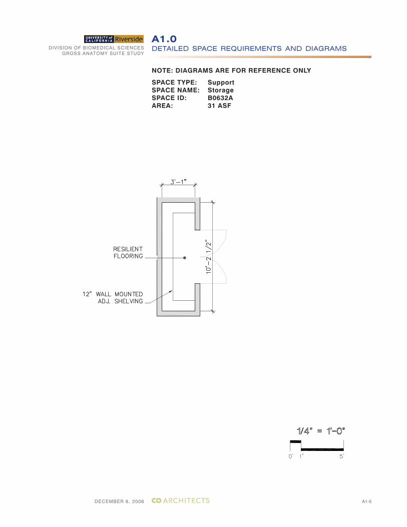
SPACE TYPE: SupportSPACE NAME: StorageSPACE ID: B0632AAREA: 31 ASF
DECEMBER 6, 2006
DIVISION OF BIOMEDICAL SCIENCESGROSS ANATOMY SUITE STUDY
A1-6
DETAILED SPACE REQUIREMENTS AND DIAGRAMSA1.0
NOTE: DIAGRAMS ARE FOR REFERENCE ONLY
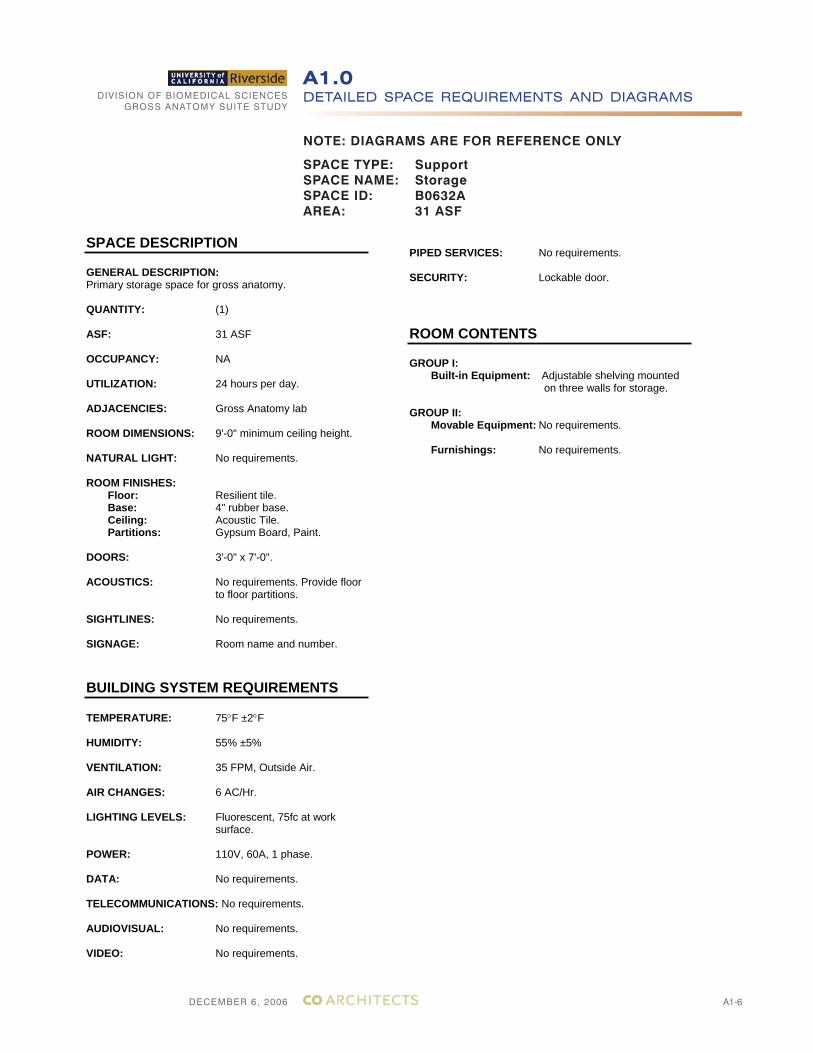
SPACE TYPE: SupportSPACE NAME: StorageSPACE ID: B0632AAREA: 31 ASF
SPACE DESCRIPTION
GENERAL DESCRIPTION:Primary storage space for gross anatomy.
QUANTITY: (1)
ASF: 31 ASF
OCCUPANCY: NA
UTILIZATION: 24 hours per day.
ADJACENCIES: Gross Anatomy lab
ROOM DIMENSIONS: 9'-0" minimum ceiling height.
NATURAL LIGHT: No requirements.
ROOM FINISHES: Floor: Resilient tile.
Base: 4" rubber base. Ceiling: Acoustic Tile. Partitions: Gypsum Board, Paint.
DOORS: 3'-0" x 7'-0".
ACOUSTICS: No requirements. Provide floor to floor partitions.
SIGHTLINES: No requirements.
SIGNAGE: Room name and number.
BUILDING SYSTEM REQUIREMENTS
TEMPERATURE: 75 F ±2 F
HUMIDITY: 55% ±5%
VENTILATION: 35 FPM, Outside Air.
AIR CHANGES: 6 AC/Hr.
LIGHTING LEVELS: Fluorescent, 75fc at work surface.
POWER: 110V, 60A, 1 phase.
DATA: No requirements.
TELECOMMUNICATIONS: No requirements.
AUDIOVISUAL: No requirements.
VIDEO: No requirements.
PIPED SERVICES: No requirements.
SECURITY: Lockable door.
ROOM CONTENTS
GROUP I: Built-in Equipment: Adjustable shelving mounted
on three walls for storage.
GROUP II: Movable Equipment: No requirements.
Furnishings: No requirements.
DECEMBER 6, 2006
DIVISION OF BIOMEDICAL SCIENCESGROSS ANATOMY SUITE STUDY
A1-7
DETAILED SPACE REQUIREMENTS AND DIAGRAMSA1.0
NOTE: DIAGRAMS ARE FOR REFERENCE ONLY
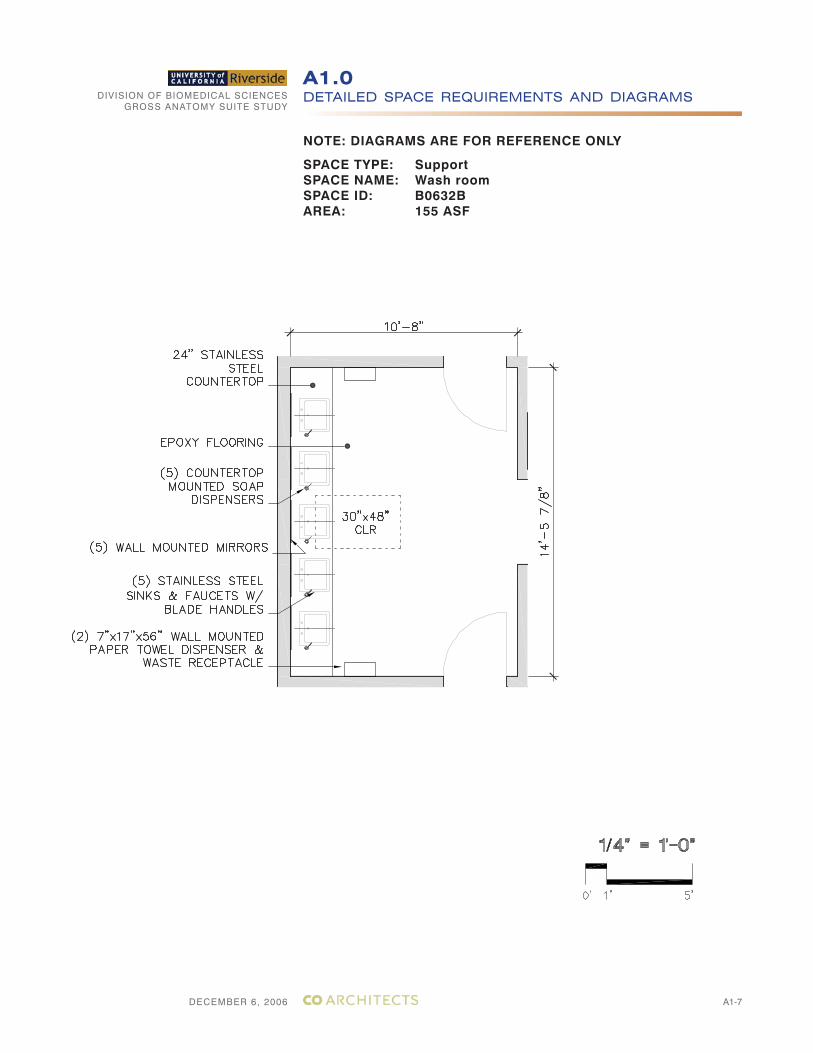
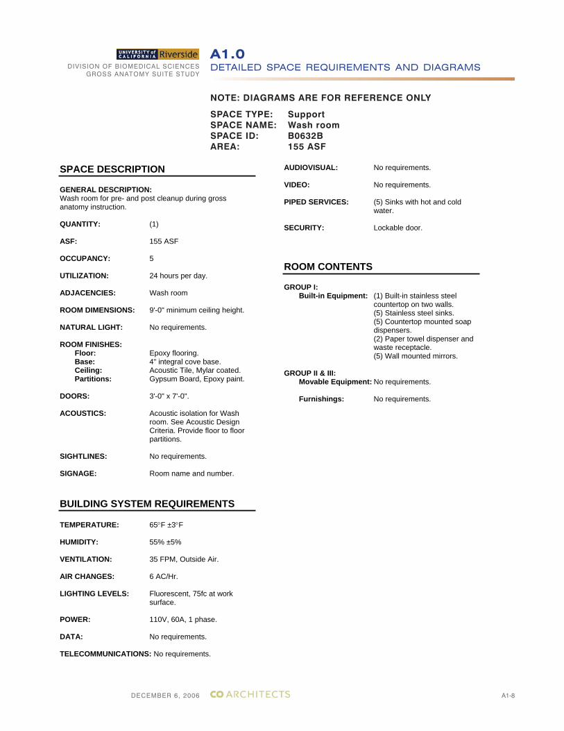
SPACE TYPE: SupportSPACE NAME: Wash roomSPACE ID: B0632BAREA: 155 ASF
DECEMBER 6, 2006
DIVISION OF BIOMEDICAL SCIENCESGROSS ANATOMY SUITE STUDY
A1-8
DETAILED SPACE REQUIREMENTS AND DIAGRAMSA1.0
NOTE: DIAGRAMS ARE FOR REFERENCE ONLY
SPACE DESCRIPTION
GENERAL DESCRIPTION:Wash room for pre- and post cleanup during gross anatomy instruction.
QUANTITY: (1)
ASF: 155 ASF
OCCUPANCY: 5
UTILIZATION: 24 hours per day.
ADJACENCIES: Wash room
ROOM DIMENSIONS: 9'-0" minimum ceiling height.
NATURAL LIGHT: No requirements.
ROOM FINISHES: Floor: Epoxy flooring.
Base: 4" integral cove base. Ceiling: Acoustic Tile, Mylar coated. Partitions: Gypsum Board, Epoxy paint.
DOORS: 3'-0" x 7'-0".
ACOUSTICS: Acoustic isolation for Wash room. See Acoustic Design Criteria. Provide floor to floor partitions.
SIGHTLINES: No requirements.
SIGNAGE: Room name and number.
BUILDING SYSTEM REQUIREMENTS
TEMPERATURE: 65 F ±3 F
HUMIDITY: 55% ±5%
VENTILATION: 35 FPM, Outside Air.
AIR CHANGES: 6 AC/Hr.
LIGHTING LEVELS: Fluorescent, 75fc at work surface.
POWER: 110V, 60A, 1 phase.
DATA: No requirements.
TELECOMMUNICATIONS: No requirements.
AUDIOVISUAL: No requirements.
VIDEO: No requirements.
PIPED SERVICES: (5) Sinks with hot and cold water.
SECURITY: Lockable door.
ROOM CONTENTS
GROUP I: Built-in Equipment: (1) Built-in stainless steel
countertop on two walls. (5) Stainless steel sinks.
(5) Countertop mounted soap dispensers.
(2) Paper towel dispenser and waste receptacle.
(5) Wall mounted mirrors.
GROUP II & III: Movable Equipment: No requirements.
Furnishings: No requirements.
SPACE TYPE: SupportSPACE NAME: Wash roomSPACE ID: B0632BAREA: 155 ASF
DECEMBER 6, 2006
DIVISION OF BIOMEDICAL SCIENCESGROSS ANATOMY SUITE STUDY
A1-9
DETAILED SPACE REQUIREMENTS AND DIAGRAMSA1.0
NOTE: DIAGRAMS ARE FOR REFERENCE ONLY
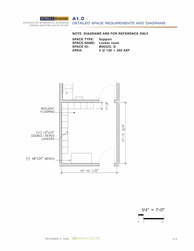
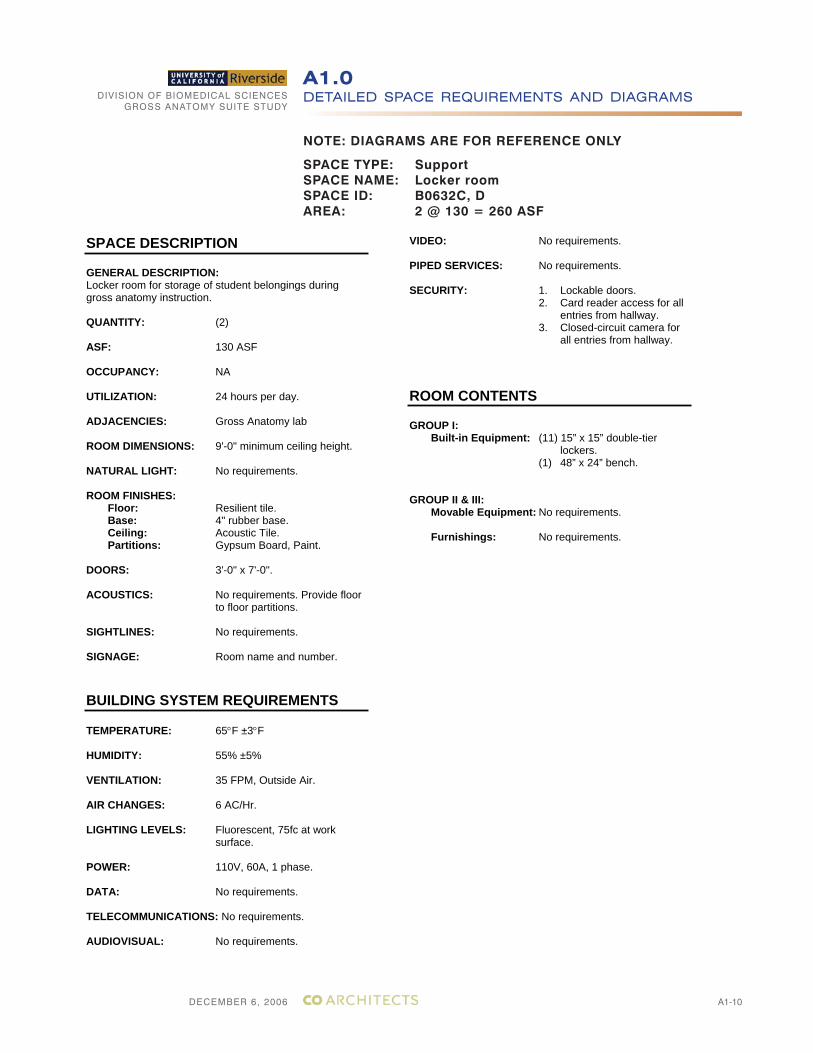
SPACE TYPE: SupportSPACE NAME: Locker roomSPACE ID: B0632C, DAREA: 2 @ 130 = 260 ASF
DECEMBER 6, 2006
DIVISION OF BIOMEDICAL SCIENCESGROSS ANATOMY SUITE STUDY
A1-10
DETAILED SPACE REQUIREMENTS AND DIAGRAMSA1.0
NOTE: DIAGRAMS ARE FOR REFERENCE ONLY
SPACE TYPE: SupportSPACE NAME: Locker roomSPACE ID: B0632C, DAREA: 2 @ 130 = 260 ASF
SPACE DESCRIPTION
GENERAL DESCRIPTION:Locker room for storage of student belongings during gross anatomy instruction.
QUANTITY: (2)
ASF: 130 ASF
OCCUPANCY: NA
UTILIZATION: 24 hours per day.
ADJACENCIES: Gross Anatomy lab
ROOM DIMENSIONS: 9'-0" minimum ceiling height.
NATURAL LIGHT: No requirements.
ROOM FINISHES: Floor: Resilient tile.
Base: 4" rubber base. Ceiling: Acoustic Tile. Partitions: Gypsum Board, Paint.
DOORS: 3'-0" x 7'-0".
ACOUSTICS: No requirements. Provide floor to floor partitions.
SIGHTLINES: No requirements.
SIGNAGE: Room name and number.
BUILDING SYSTEM REQUIREMENTS
TEMPERATURE: 65 F ±3 F
HUMIDITY: 55% ±5%
VENTILATION: 35 FPM, Outside Air.
AIR CHANGES: 6 AC/Hr.
LIGHTING LEVELS: Fluorescent, 75fc at work surface.
POWER: 110V, 60A, 1 phase.
DATA: No requirements.
TELECOMMUNICATIONS: No requirements.
AUDIOVISUAL: No requirements.
VIDEO: No requirements.
PIPED SERVICES: No requirements.
SECURITY: 1. Lockable doors. 2. Card reader access for all
entries from hallway. 3. Closed-circuit camera for
all entries from hallway.
ROOM CONTENTS
GROUP I: Built-in Equipment: (11) 15” x 15” double-tier
lockers.(1) 48” x 24” bench.
GROUP II & III: Movable Equipment: No requirements.
Furnishings: No requirements.
DECEMBER 6, 2006
DIVISION OF BIOMEDICAL SCIENCESGROSS ANATOMY SUITE STUDY
A1-11
DETAILED SPACE REQUIREMENTS AND DIAGRAMSA1.0
NOTE: DIAGRAMS ARE FOR REFERENCE ONLY
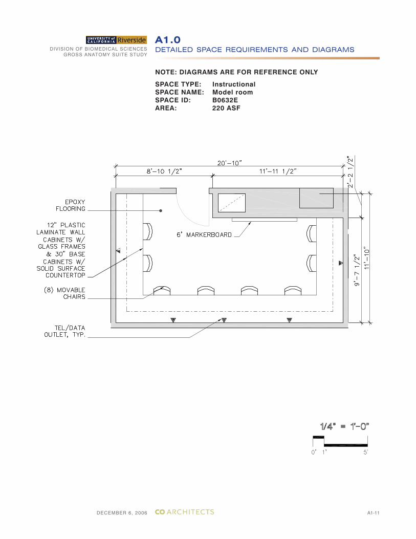
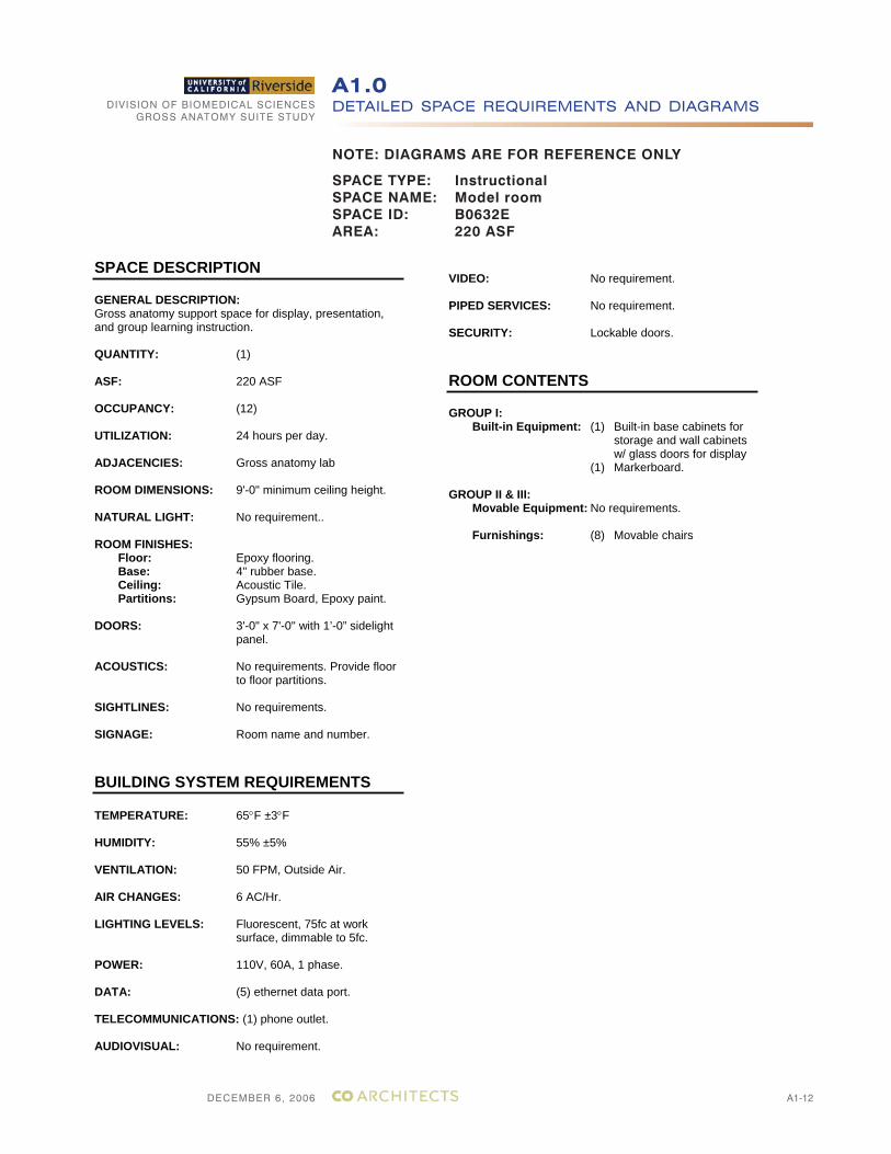
SPACE TYPE: InstructionalSPACE NAME: Model roomSPACE ID: B0632EAREA: 220 ASF
DECEMBER 6, 2006
DIVISION OF BIOMEDICAL SCIENCESGROSS ANATOMY SUITE STUDY
A1-12
DETAILED SPACE REQUIREMENTS AND DIAGRAMSA1.0
NOTE: DIAGRAMS ARE FOR REFERENCE ONLY
SPACE TYPE: InstructionalSPACE NAME: Model roomSPACE ID: B0632EAREA: 220 ASF
SPACE DESCRIPTION
GENERAL DESCRIPTION:Gross anatomy support space for display, presentation, and group learning instruction.
QUANTITY: (1)
ASF: 220 ASF
OCCUPANCY: (12)
UTILIZATION: 24 hours per day.
ADJACENCIES: Gross anatomy lab
ROOM DIMENSIONS: 9'-0" minimum ceiling height.
NATURAL LIGHT: No requirement..
ROOM FINISHES: Floor: Epoxy flooring.
Base: 4" rubber base. Ceiling: Acoustic Tile. Partitions: Gypsum Board, Epoxy paint.
DOORS: 3'-0" x 7'-0" with 1’-0” sidelight panel.
ACOUSTICS: No requirements. Provide floor to floor partitions.
SIGHTLINES: No requirements.
SIGNAGE: Room name and number.
BUILDING SYSTEM REQUIREMENTS
TEMPERATURE: 65 F ±3 F
HUMIDITY: 55% ±5%
VENTILATION: 50 FPM, Outside Air.
AIR CHANGES: 6 AC/Hr.
LIGHTING LEVELS: Fluorescent, 75fc at work surface, dimmable to 5fc.
POWER: 110V, 60A, 1 phase.
DATA: (5) ethernet data port.
TELECOMMUNICATIONS: (1) phone outlet.
AUDIOVISUAL: No requirement.
VIDEO: No requirement.
PIPED SERVICES: No requirement.
SECURITY: Lockable doors.
ROOM CONTENTS
GROUP I: Built-in Equipment: (1) Built-in base cabinets for
storage and wall cabinets w/ glass doors for display
(1) Markerboard.
GROUP II & III: Movable Equipment: No requirements.
Furnishings: (8) Movable chairs
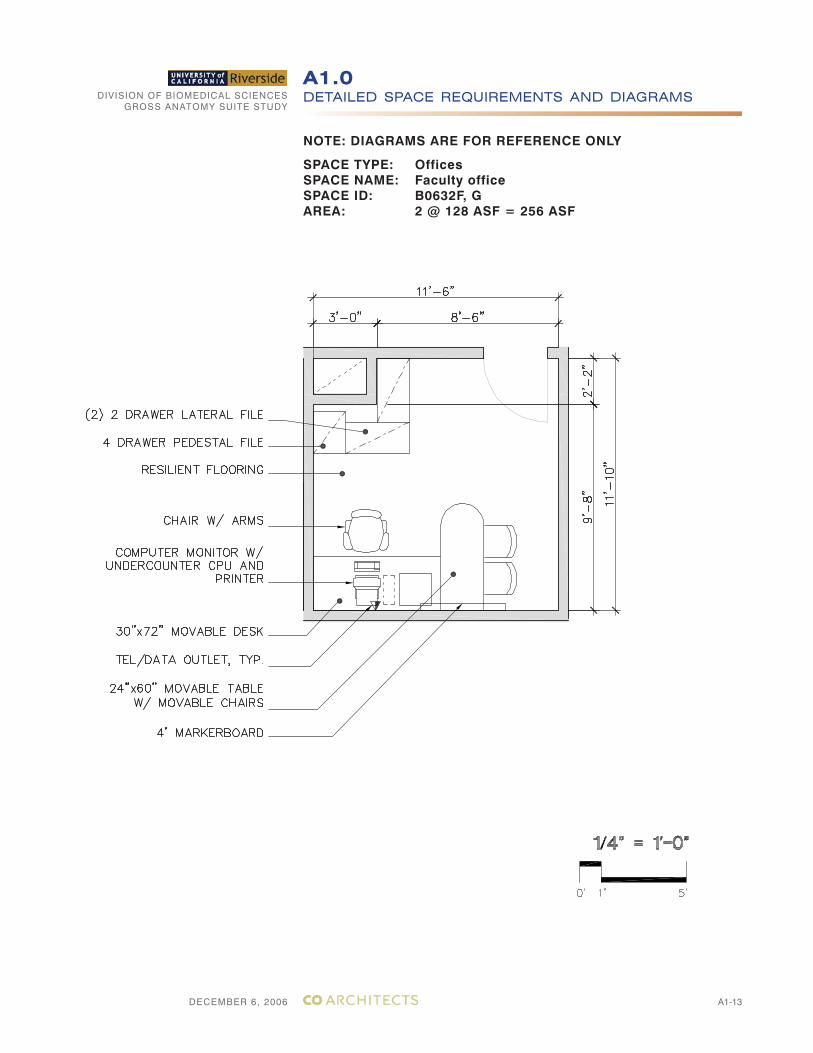
DECEMBER 6, 2006
DIVISION OF BIOMEDICAL SCIENCESGROSS ANATOMY SUITE STUDY
A1-13
DETAILED SPACE REQUIREMENTS AND DIAGRAMSA1.0
NOTE: DIAGRAMS ARE FOR REFERENCE ONLY
SPACE TYPE: OfficesSPACE NAME: Faculty officeSPACE ID: B0632F, GAREA: 2 @ 128 ASF = 256 ASF
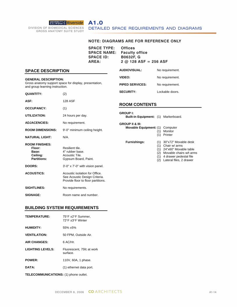
DECEMBER 6, 2006
DIVISION OF BIOMEDICAL SCIENCESGROSS ANATOMY SUITE STUDY
A1-14
DETAILED SPACE REQUIREMENTS AND DIAGRAMSA1.0
NOTE: DIAGRAMS ARE FOR REFERENCE ONLY
SPACE DESCRIPTION
GENERAL DESCRIPTION:Gross anatomy support space for display, presentation, and group learning instruction.
QUANTITY: (2)
ASF: 128 ASF
OCCUPANCY: (1)
UTILIZATION: 24 hours per day.
ADJACENCIES: No requirement.
ROOM DIMENSIONS: 9'-0" minimum ceiling height.
NATURAL LIGHT: N/A.
ROOM FINISHES: Floor: Resilient tile.
Base: 4" rubber base. Ceiling: Acoustic Tile. Partitions: Gypsum Board, Paint.
DOORS: 3'-0" x 7'-0" with vision panel.
ACOUSTICS: Acoustic isolation for Office. See Acoustic Design Criteria. Provide floor to floor partitions.
SIGHTLINES: No requirements.
SIGNAGE: Room name and number.
BUILDING SYSTEM REQUIREMENTS
TEMPERATURE: 75 F ±2 F Summer,72 F ±3 F Winter
HUMIDITY: 55% ±5%
VENTILATION: 50 FPM, Outside Air.
AIR CHANGES: 6 AC/Hr.
LIGHTING LEVELS: Fluorescent, 75fc at work surface.
POWER: 110V, 60A, 1 phase.
DATA: (1) ethernet data port.
TELECOMMUNICATIONS: (1) phone outlet.
AUDIOVISUAL: No requirement.
VIDEO: No requirement.
PIPED SERVICES: No requirement.
SECURITY: Lockable doors.
ROOM CONTENTS
GROUP I: Built-in Equipment: (1) Markerboard.
GROUP II & III: Movable Equipment: (1) Computer
(1) Monitor (1) Printer
Furnishings: (1) 30”x72” Movable desk (1) Chair w/ arms (1) 24”x60” Movable table (2) Movable chairs w/t arms (1) 4 drawer pedestal file (2) Lateral files, 2 drawer
SPACE TYPE: OfficesSPACE NAME: Faculty officeSPACE ID: B0632F, GAREA: 2 @ 128 ASF = 256 ASF
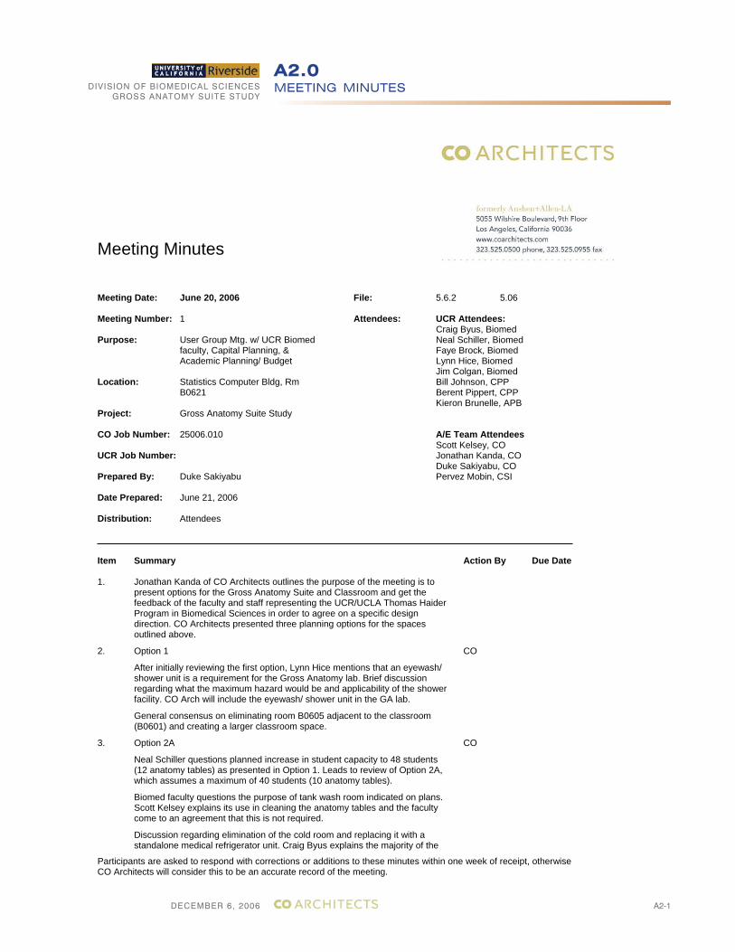
DECEMBER 6, 2006
DIVISION OF BIOMEDICAL SCIENCESGROSS ANATOMY SUITE STUDY
A2-1
MEETING MINUTESA2.0
Meeting Minutes
Participants are asked to respond with corrections or additions to these minutes within one week of receipt, otherwise CO Architects will consider this to be an accurate record of the meeting.
Meeting Date: June 20, 2006 5.06
Meeting Number: 1
Purpose: User Group Mtg. w/ UCR Biomed faculty, Capital Planning, & Academic Planning/ Budget
Location: Statistics Computer Bldg, Rm B0621
Project: Gross Anatomy Suite Study
CO Job Number: 25006.010
UCR Job Number:
Prepared By: Duke Sakiyabu
Date Prepared: June 21, 2006
Distribution: Attendees
File: 5.6.2
Attendees: UCR Attendees: Craig Byus, Biomed Neal Schiller, Biomed Faye Brock, Biomed Lynn Hice, Biomed Jim Colgan, Biomed Bill Johnson, CPP Berent Pippert, CPP Kieron Brunelle, APB
A/E Team Attendees Scott Kelsey, CO Jonathan Kanda, CO Duke Sakiyabu, CO Pervez Mobin, CSI
Item Summary Action By Due Date
1. Jonathan Kanda of CO Architects outlines the purpose of the meeting is to present options for the Gross Anatomy Suite and Classroom and get the feedback of the faculty and staff representing the UCR/UCLA Thomas Haider Program in Biomedical Sciences in order to agree on a specific design direction. CO Architects presented three planning options for the spaces outlined above.
2. Option 1
After initially reviewing the first option, Lynn Hice mentions that an eyewash/ shower unit is a requirement for the Gross Anatomy lab. Brief discussion regarding what the maximum hazard would be and applicability of the shower facility. CO Arch will include the eyewash/ shower unit in the GA lab.
General consensus on eliminating room B0605 adjacent to the classroom (B0601) and creating a larger classroom space.
CO
3. Option 2A
Neal Schiller questions planned increase in student capacity to 48 students (12 anatomy tables) as presented in Option 1. Leads to review of Option 2A, which assumes a maximum of 40 students (10 anatomy tables).
Biomed faculty questions the purpose of tank wash room indicated on plans. Scott Kelsey explains its use in cleaning the anatomy tables and the faculty come to an agreement that this is not required.
Discussion regarding elimination of the cold room and replacing it with a standalone medical refrigerator unit. Craig Byus explains the majority of the
CO
DECEMBER 6, 2006
DIVISION OF BIOMEDICAL SCIENCESGROSS ANATOMY SUITE STUDY
A2-2
MEETING MINUTESA2.0
Participants are asked to respond with corrections or additions to these minutes within one week of receipt, otherwise CO Architects will consider this to be an accurate record of the meeting.
existing cold room will be cleaned out. Jim Colgan mentions he will only need enough storage capacity for a maximum of 20 brains. Agreement that a three section medical refrigerator unit should be sufficient for present and future needs.
Jim Colgan indicates storage area should accommodate the temporary storage of medical waste, composing of 3 or 4 bags of mostly used gowns, gloves, and paper.
Berent Pippert questions faculty on whether they should consider planning for a maximum of 48 students now rather than only 40 and having to revise that number later. Comments from C. Byus and N. Schiller that they do not expect increase in students for 5-8 years. Once they reach 40-48 students they will require a new building as a medical school. Bill Johnson and faculty agree that completion of new building is unpredictable and planning for 48 students now would be preferable.
Kieron Brunelle questions whether PBL room adjacent to the GA lab could be later outfitted to accommodate increase from 40 to 48 students.
Discussion regarding the addition of a support space in the classroom space as indicated in Option 2A. After discussion of microscope storage needs and class preparation needs, consensus that support space is not required.
4. Option 2
CO Arch. presents Option 2, similar to Option 2A but accommodates 48 students (12 anatomy tables). S. Kelsey and J. Kanda mention that initial arrangement of tables and wiring for future overhead lights should be considered now to facilitate additional growth in anatomy tables and associated overhead lights.
J. Colgan states preference for 2 separate offices rather than the shared scheme as indicated on the plan. Also prefers having additional door to hallway rather than just to the GA lab. Pervez Mobin states that the GA lab would be kept at negative pressure, mitigating odors coming from GA lab.
Doors to hallway lead to discussion of security of GA lab. L. Hice states a requirement for a card reader and video camera at every entry from the hallway into the GA lab. B. Johnson mentions cost of reader/ camera but main consideration is reduction of potential entrances into the GA lab. Agreement to keep access to offices from GA lab only but CO Arch. to look into possibility of relocating door from hallway closer to offices.
Discussion turns to arrangement of students in classroom. S. Kelsey reviews how the group learning format (TEAL model) differs from a traditional didactic lecture format. C. Byus responds he is open to arrangement of students in classroom for group learning, but only if another room was available for didactic learning. B. Pippert mentions possible availability of another classroom for lecture. He is to identify which classroom and the student capacity it has. S. Kelsey states rearranging the classroom between the two learning models on a regular basis is impractical. Agreement among Biomed faculty that a group learning arrangement alone would meet resistance from other faculty members and instructors. Agreement for CO Arch. to look into table arrangement that could provide for both group learning and didactic lecture models with minimal table rearrangement.
General discussion regarding the need for existing monitors in the classroom space leads to consensus on replacing them with updated monitors (i.e. LED). Faye Brock states so long as the same media (i.e. VHS, slides, etc.) can be presented, there should be no objection among the instructors to the upgrading of A/V equipment.
CO/ CPP
DECEMBER 6, 2006
DIVISION OF BIOMEDICAL SCIENCESGROSS ANATOMY SUITE STUDY
A2-3
MEETING MINUTESA2.0
Participants are asked to respond with corrections or additions to these minutes within one week of receipt, otherwise CO Architects will consider this to be an accurate record of the meeting.
5. Cost
S. Kelsey gives rough estimate of cost as follows:
Appr. 3800 ft² of construction at $350/ ft² = $1.3 mil.
In addition, estimate $250K - $300K for A/V and equipment.
6. Agreement for CO Arch. to revise plans based on meeting and submit them to B. Johnson for review with Biomed faculty. Once approved, CO Arch to submit plans to cost estimator and schedule with B. Johnson a meeting to review revised plans and costs.
CO
End of Meeting Minutes
DECEMBER 6, 2006
DIVISION OF BIOMEDICAL SCIENCESGROSS ANATOMY SUITE STUDY
A2-4
MEETING MINUTESA2.0
Meeting Minutes
Participants are asked to respond with corrections or additions to these minutes within one week of receipt, otherwise CO Architects will consider this to be an accurate record of the meeting.
Meeting Date: August 16, 2006 5.06
Meeting Number: 2
Purpose: User Group Mtg. w/ UCR Biomed faculty, Capital Planning, & Academic Planning/ Budget
Location: Statistics Computer Bldg, Rm B0621
Project: Gross Anatomy Suite Study
CO Job Number: 25006.010
UCR Job Number:
Prepared By: Duke Sakiyabu
Date Prepared: August 17, 2006
Distribution: Attendees
File: 5.6.2
Attendees: UCR Attendees: Craig Byus, Biomed Neal Schiller, Biomed Faye Brock, Biomed Lynn Hice, Biomed Jim Colgan, Biomed Mary Ann Baker, Biomed Bill Johnson, CPP Berent Pippert, CPP Kieron Brunelle, CPP Lionel Bradford, Comm. Ross Grayson, EH+S Russell Vernon, EH+S Jason Day, Police
A/E Team Attendees Scott Kelsey, CO Jonathan Kanda, CO Duke Sakiyabu, CO Tony Ngo, CSI
Item Summary Action By Due Date
1. Bill Johnson opens meeting by reminding attendees the meeting is focused on the long-term solution to the Gross Anatomy suite/ Class lab and not the interim solution which is a separate discussion. Jonathan Kanda of CO Architects begins by asking the Biomed faculty for comments on the draft Gross Anatomy Suite draft study.
2. Neil Schiller questions the actual usage of the planned locker room. General assessment that locker room should accommodate changing scrubs and storage as opposed to only storage (w/ students changing in restrooms). This requires separate rooms for male and female students, reducing the GA lab space and the number of anatomy tables that can be accommodated. Discussion and consensus that reduction of potential class size from 48 to 40 students is acceptable.
Ross Grayson recommends including a shower into the locker room. General agreement a shower should not be included in the design, citing low potential frequency of use and significant space impact on the GA lab suite.
CO to redesign GA suite to accommodate said revisions.
CO
3. Russell Vernon questions whether the offices can exit through the GA lab if the lab is considered a high hazard space.
JK explains code allows for exiting through GA lab because the offices are considered accessory use spaces. NS explains similar conditions exist in research labs.
CO Arch to verify high hazard space conditions and exiting requirements for
CO
DECEMBER 6, 2006
DIVISION OF BIOMEDICAL SCIENCESGROSS ANATOMY SUITE STUDY
A2-5
MEETING MINUTESA2.0
Participants are asked to respond with corrections or additions to these minutes within one week of receipt, otherwise CO Architects will consider this to be an accurate record of the meeting.
GA lab.
4. NS questions faculty what AV requirements are necessary for the Model room. Mary Ann Baker explains the room is primarily for the examination of clean samples. Computer networking and multimedia presentations are stronger possibilities in this room than in the GA lab. Jim Colgan lists light boxes should be included, at one per station, mounted on the wall. Scott Kelsey asks if boxes can be replaced with computer monitors. General discussion regarding practicality of students bringing laptops through GA lab into the Model room. In all regards, confirmation from JK that infrastructure for either option will be included in cost model.
JC confirms current size of Model room (eight stations) is sufficient and should not be reduced. Storage should be utilized in base and wall cabinets wherever possible, both in the Model room and GA lab.
CO
5. Lynn Hice gives update on the installation of security cameras for the GA lab suite. Three cameras will be installed at entrances to the suite, along with swipe key and keypad access. An emergency phone will be located nearby the main entrance. Security cameras will tape to a unit, access to which Jason Day requests should be restricted. The server room on the first floor is suggested by Berent Pippert as a possible location.
6. EH+S confirms an emergency phone should be included in the GA lab. CO
7. Discussion regarding AV requirements for the Class lab focuses on requirements for the students. Although the Class lab has a wireless network in place and would be maintained, faculty recognizes need for power and more robust network connectivity for the students’ laptops. SK points out this connectivity is especially important in a group learning format. After brief review of potential seating arrangements, general consensus that floor outlets (telecom/data/power) going to powered tables should be required. A grid arrangement is appropriate since actual seating arrangement will not be determined until later. Tim Ralston and SK confirm this is part of infrastructure discussion and should be included in the revised cost model.
SK asks if Class lab should maintain a 48 student capacity, in light of the reduction in the GA lab. Craig Byus confirms capacity should be maintained to accommodate graduate students, in addition to the undergraduates.
CO
8. CO Arch presents an alternate scheme for the GA lab using sidedraft tables recommended by RG. This scheme accommodates 10 anatomy tables, each attached at one end to a duct connection at a wall.
RG presents information regarding a project similar in design and the efficacy of sidedraft tables in removing formaldehyde vapors from the cadavers.
SK lists other projects using the “ballroom” type scheme as presented in the draft study.
After discussion, JC does not see problems with the sidedraft table option from an instructional point of view.
Sidedraft option:
Pros:
- very effective in reducing formaldehyde vapors, exceeding the OSHA standard
- alcoves created by table arrangement conducive to multiple storage options
Cons:
- flexibility of table arrangement very limited
- higher premium for custom-made sidedraft tables
- dedicated ductwork for each table adds to construction costs
- high CFM requirement per table (1000 CFM) requires larger air handling unit
DECEMBER 6, 2006
DIVISION OF BIOMEDICAL SCIENCESGROSS ANATOMY SUITE STUDY
A2-6
MEETING MINUTESA2.0
Participants are asked to respond with corrections or additions to these minutes within one week of receipt, otherwise CO Architects will consider this to be an accurate record of the meeting.
Ballroom option:
Pros:
- allows for flexibility in table arrangement
- less premium attached to ductwork and air distribution
- air handling unit for this scheme can be accommodated in existing mechanical room
Cons:
- OSHA air quality standard cannot be conclusively met without actual testing
- at maximum capacity, space clearances are at the minimums
- less potential for storage
9. Bill Johnson anticipates that Physical Plant, as a maintenance issue, will require rigid connections to the sidedraft tables.
RG to contact the sidedraft table fabricator and confirm costs.
BJ should contact Pat Simone and/or Chris Flanders from Physical Plant and get them in touch with Tony Ngo to confirm the condition and capability of the existing mechanical system.
Tony Ngo to evaluate locations for a larger air handling unit associated with the sidedraft tables.
Biomed faculty to contact UCLA regarding the air quality in their GA lab, which is a ballroom scheme.
As the above information becomes available, the potential costs will be included in the cost model.
CO Arch to revise plans from faculty recommendations.
CO
UCR
Biomed
CSI
End of Meeting Minutes

DECEMBER 6, 2006
DIVISION OF BIOMEDICAL SCIENCESGROSS ANATOMY SUITE STUDY
A3-1
DETAILED COST PLANA3.0
CONCEPT DESIGNCOST PLAN
for
Biomedical Science StudyUniversity of California, RiversideRiverside, California
December 9, 2006
DECEMBER 6, 2006
DIVISION OF BIOMEDICAL SCIENCESGROSS ANATOMY SUITE STUDY
A3-2
DETAILED COST PLANA3.0
CONCEPT DESIGN COST PLAN
for
Biomedical Science StudyUniversity of California, RiversideRiverside, California
CO Architects 5055 Wilshire Boulevard9th FloorLos Angeles, California 90036
Tel: (323) 525-0500Fax: (323) 525-0955
December 9, 2006 301 Arizona AvenueSuite 301Santa MonicaCalifornia 90401Tel: 310.393.9411Fax: 310.393.7493www.davislangdon.com
DECEMBER 6, 2006
DIVISION OF BIOMEDICAL SCIENCESGROSS ANATOMY SUITE STUDY
A3-3
DETAILED COST PLANA3.0
Biomedical Science Study Concept Design Cost PlanUniversity of California, Riverside December 9, 2006Riverside, California 0168-7497.110
CONTENTS
Page Nos.
Basis of Cost Plan 1
Inclusions 2
Exclusions 4
Overall Summary 5
Renovation Component Summary 7
Premium For Downdraft Tables Component Summary 16
Group II / III Furnishings Component Summary 20
DECEMBER 6, 2006
DIVISION OF BIOMEDICAL SCIENCESGROSS ANATOMY SUITE STUDY
A3-4
DETAILED COST PLANA3.0
Biomedical Science Study Concept Design Cost PlanUniversity of California, Riverside December 9, 2006Riverside, California 0168-7497.110
BASIS OF COST PLAN
Cost Plan Prepared From Dated Received
Outline SpecificationGross Anatomy Suite Study DPP 7/20/2006 8/2/2006
Discussions with the Project Architect and Engineers
Conditions of Construction
The pricing is based on the following general conditions of construction
A start date of May 2008
A construction period of 5 months
The general contract will be competitively bid with qualified general and main subcontractors
There will not be small business set aside requirements
The contractor will be required to pay prevailing wages
The general contractor may not have full access to the site during normal business hours
There are no phasing requirements
DECEMBER 6, 2006
DIVISION OF BIOMEDICAL SCIENCESGROSS ANATOMY SUITE STUDY
A3-5
DETAILED COST PLANA3.0
Biomedical Science Study Concept Design Cost PlanUniversity of California, Riverside December 9, 2006Riverside, California 0168-7497.110
INCLUSIONS
This project consists of the renovation of 4,380 sf of existing space to become Biomedical Science program.
The cost plan includes the following functions for building systems:
Floor and roof structure includes general repair to floor slabs following the interior demolition of the existingspace and the miscellaneous alterations to accept the new program.
Interior partitions, doors and framing includes new partitions, doors and glazing
Floor, wall and ceiling finish includes new finish for all new program spaces.
Function equipment and specialties include corner guards and crash rails, washroom compartments andaccessories, shelving, cabinets, counters and casework, light control and vision equipment, lockers, misc.medical equipment.
Plumbing includes sanitary and institutional fixtures, floor drains and associated connection pipe work.
Heating, Ventilating & Air Conditioning includes campus provided chilling, steam and heating, pipe workdistribution including heated hot, chilled, equipment cooling, steam and condensate return, (1) new airhandling unit and humidification. Air distribution and return, including biomedical exhaust ventilation,building management and laboratory pressurization controls and general ventilation.
Electrical includes (E) normal power generation and distribution, (E) emergency power generation anddistribution, machine and equipment and user convenience power, lighting, telephone/data, MATV andaudio/visual - conduit only, complete fire alarm system and allowance for security.
Fire protection includes a complete automatic wet sprinkler system - reconfigure (E).
Demolition includes demolishing the interior existing fitout.
DECEMBER 6, 2006
DIVISION OF BIOMEDICAL SCIENCESGROSS ANATOMY SUITE STUDY
A3-6
DETAILED COST PLANA3.0
Biomedical Science Study Concept Design Cost PlanUniversity of California, Riverside December 9, 2006Riverside, California 0168-7497.110
INCLUSIONS
BIDDING PROCESS - MARKET CONDITIONS
This document is based on the measurement and pricing of quantities wherever information is providedand/or reasonable assumptions for other work not covered in the drawings or specifications, as stated withinthis document. Unit rates have been obtained from historical records and/or discussion with contractors.The unit rates reflect current bid costs in the area. All unit rates relevant to subcontractor work include thesubcontractors overhead and profit unless otherwise stated. The mark-ups cover the costs of field overhead,home office overhead and profit and range from 15% to 25% of the cost for a particular item of work.
Pricing reflects probable construction costs obtainable in the project locality on the date of this statement ofprobable costs. This estimate is a determination of fair market value for the construction of this project. It isnot a prediction of low bid. Pricing assumes competitive bidding for every portion of the construction work forall subcontractors and general contractors, with a minimum of 3 bidders for all items of subcontracted workand 3-4 general contractor bids. Experience indicates that a fewer number of bidders may result in higherbids, conversely an increased number of bidders may result in more competitive bids.
Since Davis Langdon has no control over the cost of labor, material, equipment, or over the contractor'smethod of determining prices, or over the competitive bidding or market conditions at the time of bid, thestatement of probable construction cost is based on industry practice, professional experience andqualifications, and represents Davis Langdon's best judgement as professional construction consultantfamiliar with the construction industry. However, Davis Langdon cannot and does not guarantee that theproposals, bids, or the construction cost will not vary from opinions of probable cost prepared by them.

DECEMBER 6, 2006
DIVISION OF BIOMEDICAL SCIENCESGROSS ANATOMY SUITE STUDY
A3-7
DETAILED COST PLANA3.0
Biomedical Science Study Concept Design Cost PlanUniversity of California, Riverside December 9, 2006Riverside, California 0168-7497.110
EXCLUSIONSOwner supplied and installed furniture, fixtures and equipment (Group II/III equipment and furnishings are included separately as additional scope items.)
Loose furniture and equipment except as specifically identified
Hazardous material handling, disposal / abatement
Compression of schedule, premium or shift work, and restrictions on the contractor's working hours
Design, testing, inspection or construction management fees
Architectural and design fees
Scope change and post contract contingencies
Assessments, taxes, finance, legal and development charges
Environmental impact mitigation
Builder's risk, project wrap-up and other owner provided insurance program
Land and easement acquisition
Cost escalation beyond a start date of May 2008
Audio visual equipment (Group II/III equipment and furnishings are included separately as additional scope
Medical and laboratory gases - CA, Vac, O2 etc.
Domestic hot water heater - upgrades
Roof drainage reconfiguration.
CHW/HHW circulatory pumps
(E) classroom air handler - upgrades
Stainless steel biomedical exhaust ductwork
Upgrades to (E) normal and emergency power distribution equipment and feeders
UPS - By Owner
Public address
Centralized clocks
Utility upgrades
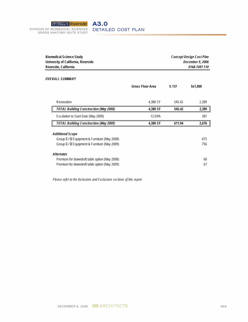
DECEMBER 6, 2006
DIVISION OF BIOMEDICAL SCIENCESGROSS ANATOMY SUITE STUDY
A3-8
DETAILED COST PLANA3.0
Biomedical Science Study Concept Design Cost PlanUniversity of California, Riverside December 9, 2006Riverside, California 0168-7497.110
OVERALL SUMMARY
Gross Floor Area $ / SF $x1,000
Renovation 4,380 SF 545.42 2,389
TOTAL Building Construction (May 2008) 4,380 SF 545.42 2,389
Escalation to Start Date (May 2009) 12.03% 287
TOTAL Building Construction (May 2009) 4,380 SF 611.04 2,676
Additional ScopeGroup II / III Equipment & Furniture (May 2008) 675Group II / III Equipment & Furniture (May 2009) 756
AlternatesPremium for downdraft table option (May 2008) 60Premium for downdraft table option (May 2009) 67
Please refer to the Inclusions and Exclusions sections of this report
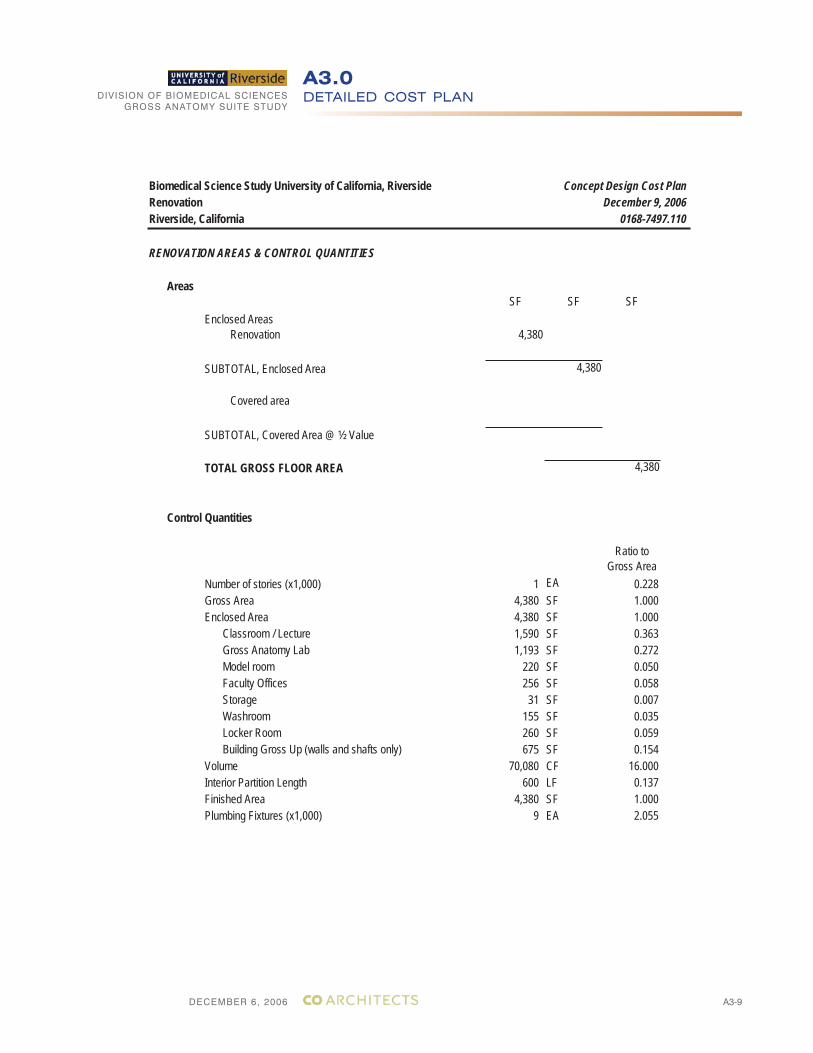
DECEMBER 6, 2006
DIVISION OF BIOMEDICAL SCIENCESGROSS ANATOMY SUITE STUDY
A3-9
DETAILED COST PLANA3.0
Biomedical Science Study University of California, Riverside Concept Design Cost PlanRenovation December 9, 2006Riverside, California 0168-7497.110
RENOVATION AREAS & CONTROL QUANTITIES
AreasSF SF SF
Enclosed AreasRenovation 4,380
SUBTOTAL, Enclosed Area 4,380
Covered area
SUBTOTAL, Covered Area @ ½ Value
TOTAL GROSS FLOOR AREA 4,380
Control Quantities
Ratio to Gross Area
Number of stories (x1,000) 1 EA 0.228Gross Area 4,380 SF 1.000Enclosed Area 4,380 SF 1.000
Classroom / Lecture 1,590 SF 0.363Gross Anatomy Lab 1,193 SF 0.272Model room 220 SF 0.050Faculty Offices 256 SF 0.058Storage 31 SF 0.007Washroom 155 SF 0.035Locker Room 260 SF 0.059Building Gross Up (walls and shafts only) 675 SF 0.154
Volume 70,080 CF 16.000Interior Partition Length 600 LF 0.137Finished Area 4,380 SF 1.000Plumbing Fixtures (x1,000) 9 EA 2.055
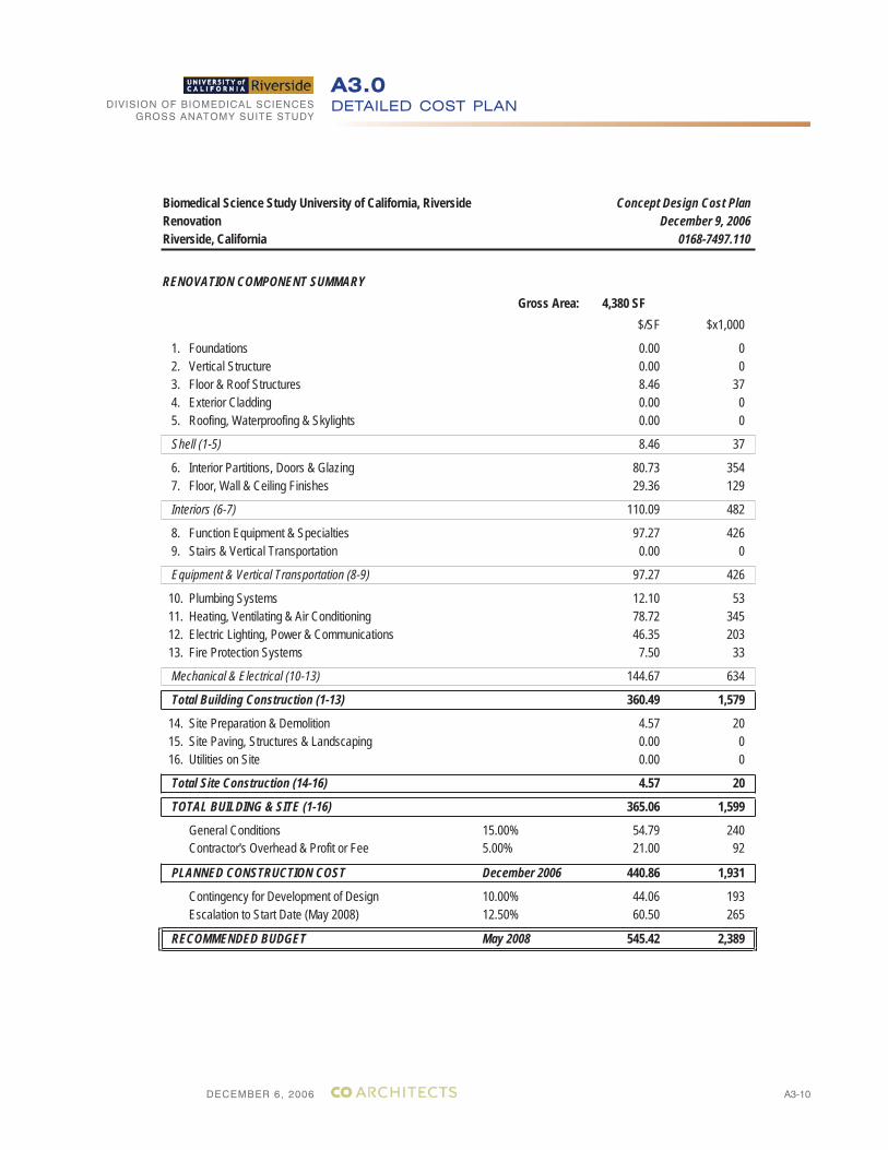
DECEMBER 6, 2006
DIVISION OF BIOMEDICAL SCIENCESGROSS ANATOMY SUITE STUDY
A3-10
DETAILED COST PLANA3.0
Biomedical Science Study University of California, Riverside Concept Design Cost PlanRenovation December 9, 2006Riverside, California 0168-7497.110
RENOVATION COMPONENT SUMMARYGross Area: 4,380 SF
$/SF $x1,000
1. Foundations 0.00 0 2. Vertical Structure 0.00 0 3. Floor & Roof Structures 8.46 37 4. Exterior Cladding 0.00 0 5. Roofing, Waterproofing & Skylights 0.00 0
Shell (1-5) 8.46 37
6. Interior Partitions, Doors & Glazing 80.73 354 7. Floor, Wall & Ceiling Finishes 29.36 129
Interiors (6-7) 110.09 482
8. Function Equipment & Specialties 97.27 426 9. Stairs & Vertical Transportation 0.00 0
Equipment & Vertical Transportation (8-9) 97.27 426
10. Plumbing Systems 12.10 53 11. Heating, Ventilating & Air Conditioning 78.72 345 12. Electric Lighting, Power & Communications 46.35 203 13. Fire Protection Systems 7.50 33
Mechanical & Electrical (10-13) 144.67 634
Total Building Construction (1-13) 360.49 1,579
14. Site Preparation & Demolition 4.57 20 15. Site Paving, Structures & Landscaping 0.00 0 16. Utilities on Site 0.00 0
Total Site Construction (14-16) 4.57 20
TOTAL BUILDING & SITE (1-16) 365.06 1,599
General Conditions 15.00% 54.79 240Contractor's Overhead & Profit or Fee 5.00% 21.00 92
PLANNED CONSTRUCTION COST December 2006 440.86 1,931
Contingency for Development of Design 10.00% 44.06 193Escalation to Start Date (May 2008) 12.50% 60.50 265
RECOMMENDED BUDGET May 2008 545.42 2,389
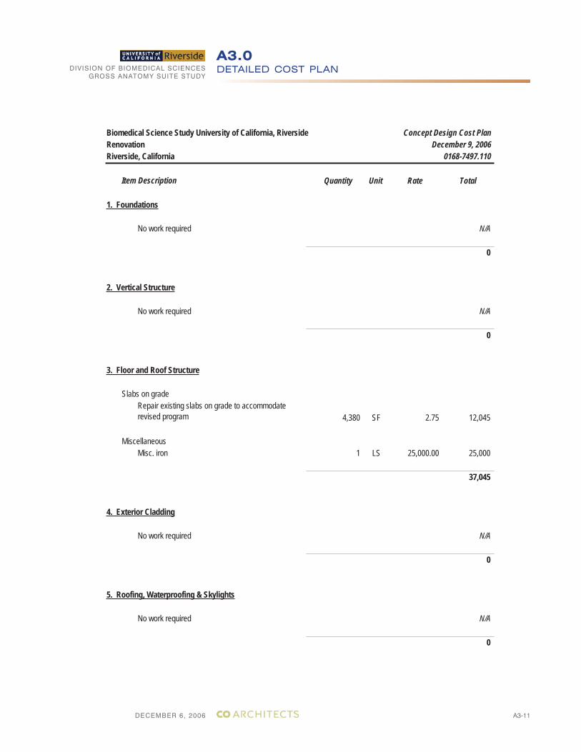
DECEMBER 6, 2006
DIVISION OF BIOMEDICAL SCIENCESGROSS ANATOMY SUITE STUDY
A3-11
DETAILED COST PLANA3.0
Biomedical Science Study University of California, Riverside Concept Design Cost PlanRenovation December 9, 2006Riverside, California 0168-7497.110
Item Description Quantity Unit Rate Total
1. Foundations
No work required N/A
0
2. Vertical Structure
No work required N/A
0
3. Floor and Roof Structure
Slabs on gradeRepair existing slabs on grade to accommodate revised program 4,380 SF 2.75 12,045
MiscellaneousMisc. iron 1 LS 25,000.00 25,000
37,045
4. Exterior Cladding
No work required N/A
0
5. Roofing, Waterproofing & Skylights
No work required N/A
0
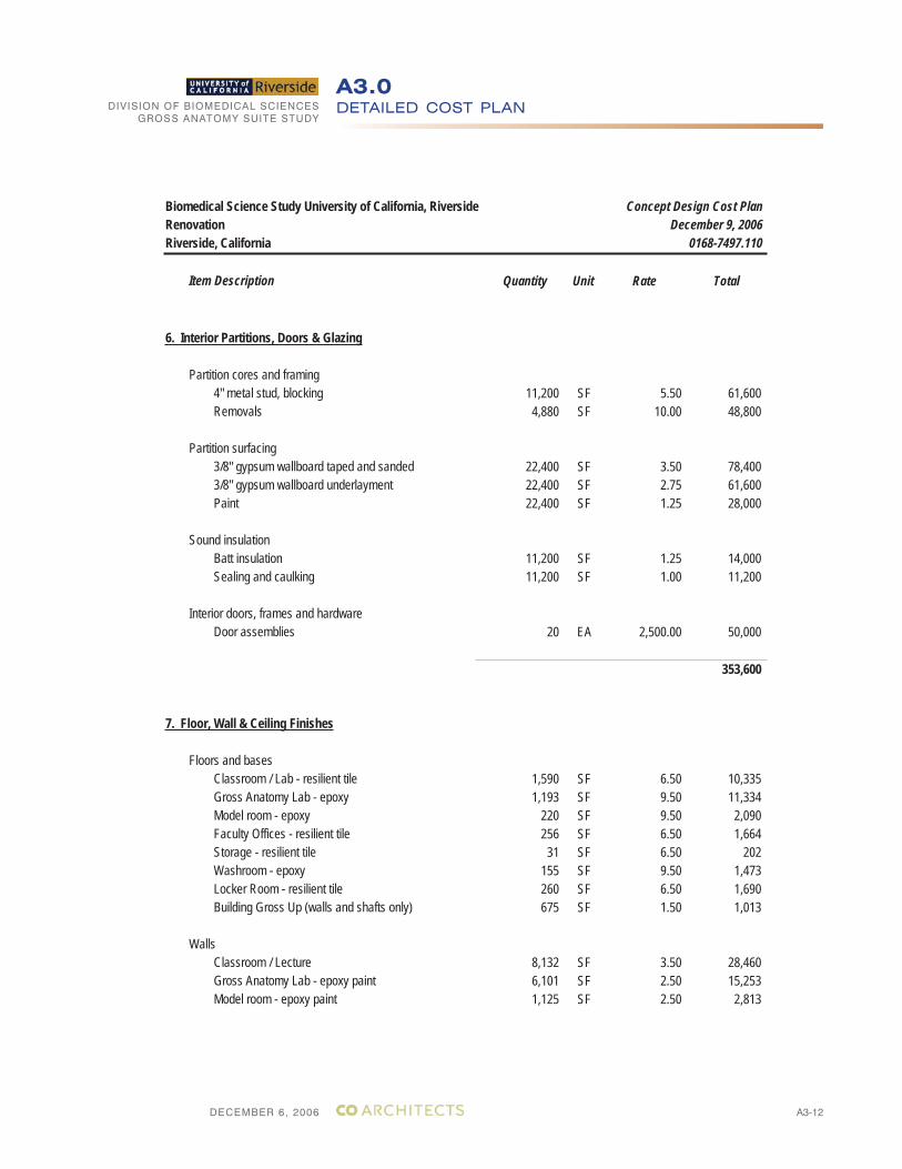
DECEMBER 6, 2006
DIVISION OF BIOMEDICAL SCIENCESGROSS ANATOMY SUITE STUDY
A3-12
DETAILED COST PLANA3.0
Biomedical Science Study University of California, Riverside Concept Design Cost PlanRenovation December 9, 2006Riverside, California 0168-7497.110
Item Description Quantity Unit Rate Total
6. Interior Partitions, Doors & Glazing
Partition cores and framing4" metal stud, blocking 11,200 SF 5.50 61,600Removals 4,880 SF 10.00 48,800
Partition surfacing3/8" gypsum wallboard taped and sanded 22,400 SF 3.50 78,4003/8" gypsum wallboard underlayment 22,400 SF 2.75 61,600Paint 22,400 SF 1.25 28,000
Sound insulationBatt insulation 11,200 SF 1.25 14,000Sealing and caulking 11,200 SF 1.00 11,200
Interior doors, frames and hardwareDoor assemblies 20 EA 2,500.00 50,000
353,600
7. Floor, Wall & Ceiling Finishes
Floors and basesClassroom / Lab - resilient tile 1,590 SF 6.50 10,335Gross Anatomy Lab - epoxy 1,193 SF 9.50 11,334Model room - epoxy 220 SF 9.50 2,090Faculty Offices - resilient tile 256 SF 6.50 1,664Storage - resilient tile 31 SF 6.50 202Washroom - epoxy 155 SF 9.50 1,473Locker Room - resilient tile 260 SF 6.50 1,690Building Gross Up (walls and shafts only) 675 SF 1.50 1,013
WallsClassroom / Lecture 8,132 SF 3.50 28,460Gross Anatomy Lab - epoxy paint 6,101 SF 2.50 15,253Model room - epoxy paint 1,125 SF 2.50 2,813
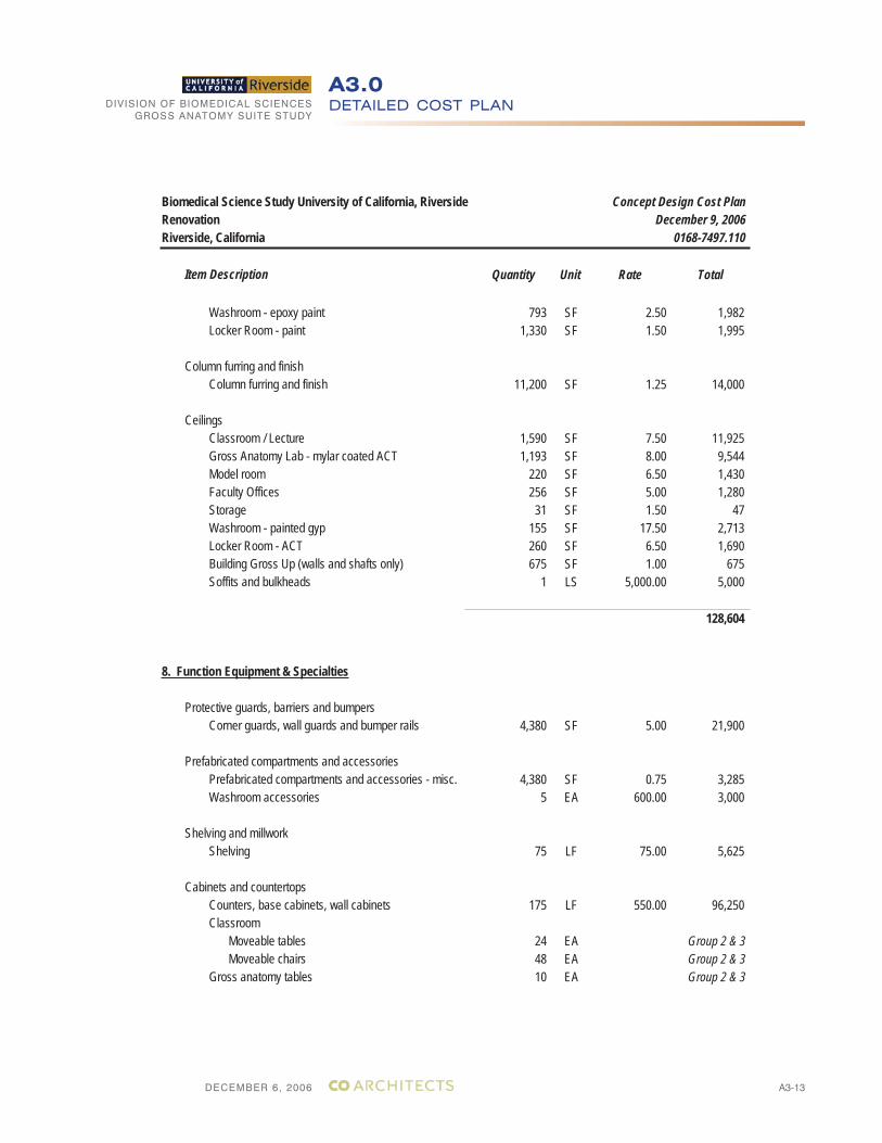
DECEMBER 6, 2006
DIVISION OF BIOMEDICAL SCIENCESGROSS ANATOMY SUITE STUDY
A3-13
DETAILED COST PLANA3.0
Biomedical Science Study University of California, Riverside Concept Design Cost PlanRenovation December 9, 2006Riverside, California 0168-7497.110
Item Description Quantity Unit Rate Total
Washroom - epoxy paint 793 SF 2.50 1,982Locker Room - paint 1,330 SF 1.50 1,995
Column furring and finishColumn furring and finish 11,200 SF 1.25 14,000
CeilingsClassroom / Lecture 1,590 SF 7.50 11,925Gross Anatomy Lab - mylar coated ACT 1,193 SF 8.00 9,544Model room 220 SF 6.50 1,430Faculty Offices 256 SF 5.00 1,280Storage 31 SF 1.50 47Washroom - painted gyp 155 SF 17.50 2,713Locker Room - ACT 260 SF 6.50 1,690Building Gross Up (walls and shafts only) 675 SF 1.00 675Soffits and bulkheads 1 LS 5,000.00 5,000
128,604
8. Function Equipment & Specialties
Protective guards, barriers and bumpersCorner guards, wall guards and bumper rails 4,380 SF 5.00 21,900
Prefabricated compartments and accessoriesPrefabricated compartments and accessories - misc. 4,380 SF 0.75 3,285Washroom accessories 5 EA 600.00 3,000
Shelving and millworkShelving 75 LF 75.00 5,625
Cabinets and countertopsCounters, base cabinets, wall cabinets 175 LF 550.00 96,250Classroom
Moveable tables 24 EA Group 2 & 3Moveable chairs 48 EA Group 2 & 3
Gross anatomy tables 10 EA Group 2 & 3
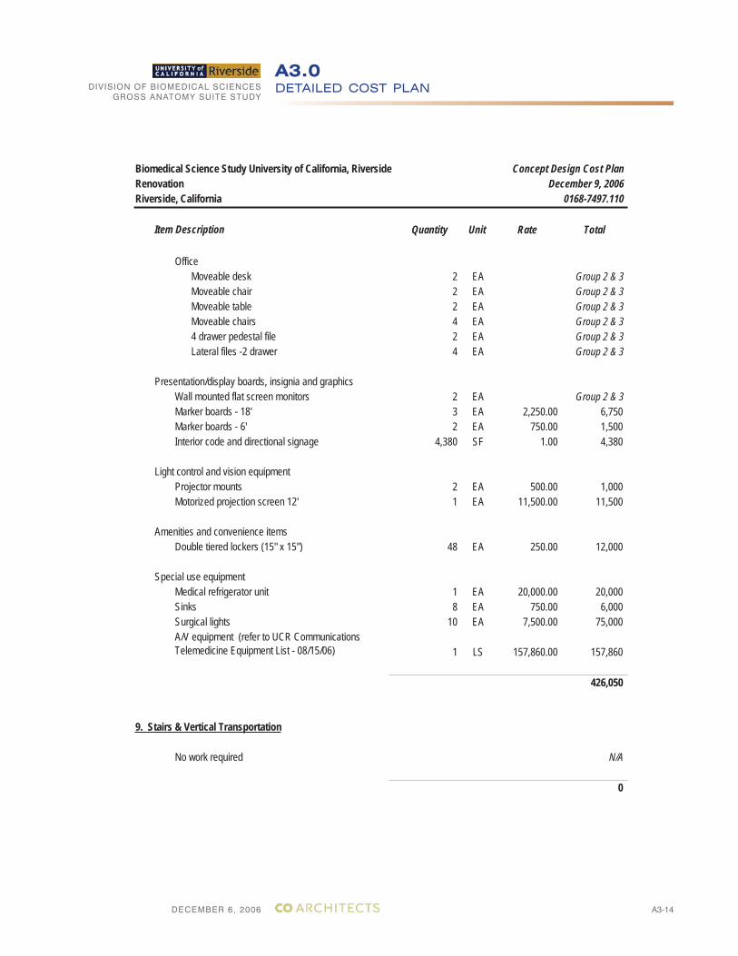
DECEMBER 6, 2006
DIVISION OF BIOMEDICAL SCIENCESGROSS ANATOMY SUITE STUDY
A3-14
DETAILED COST PLANA3.0
Biomedical Science Study University of California, Riverside Concept Design Cost PlanRenovation December 9, 2006Riverside, California 0168-7497.110
Item Description Quantity Unit Rate Total
OfficeMoveable desk 2 EA Group 2 & 3Moveable chair 2 EA Group 2 & 3Moveable table 2 EA Group 2 & 3Moveable chairs 4 EA Group 2 & 34 drawer pedestal file 2 EA Group 2 & 3Lateral files -2 drawer 4 EA Group 2 & 3
Presentation/display boards, insignia and graphicsWall mounted flat screen monitors 2 EA Group 2 & 3Marker boards - 18' 3 EA 2,250.00 6,750Marker boards - 6' 2 EA 750.00 1,500Interior code and directional signage 4,380 SF 1.00 4,380
Light control and vision equipmentProjector mounts 2 EA 500.00 1,000Motorized projection screen 12' 1 EA 11,500.00 11,500
Amenities and convenience itemsDouble tiered lockers (15" x 15") 48 EA 250.00 12,000
Special use equipmentMedical refrigerator unit 1 EA 20,000.00 20,000Sinks 8 EA 750.00 6,000Surgical lights 10 EA 7,500.00 75,000A/V equipment (refer to UCR Communications Telemedicine Equipment List - 08/15/06) 1 LS 157,860.00 157,860
426,050
9. Stairs & Vertical Transportation
No work required N/A
0
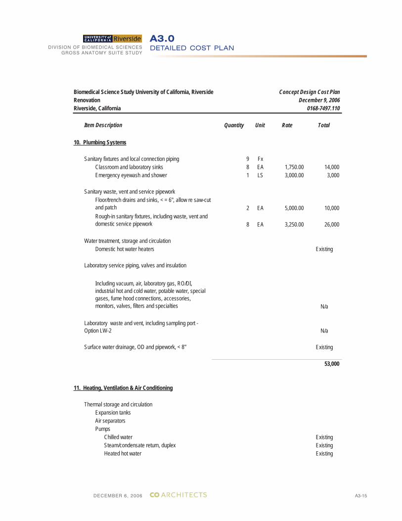
DECEMBER 6, 2006
DIVISION OF BIOMEDICAL SCIENCESGROSS ANATOMY SUITE STUDY
A3-15
DETAILED COST PLANA3.0
Biomedical Science Study University of California, Riverside Concept Design Cost PlanRenovation December 9, 2006Riverside, California 0168-7497.110
Item Description Quantity Unit Rate Total
10. Plumbing Systems
Sanitary fixtures and local connection piping 9 FxClassroom and laboratory sinks 8 EA 1,750.00 14,000Emergency eyewash and shower 1 LS 3,000.00 3,000
Sanitary waste, vent and service pipeworkFloor/trench drains and sinks, < = 6", allow re saw-cut and patch 2 EA 5,000.00 10,000Rough-in sanitary fixtures, including waste, vent and domestic service pipework 8 EA 3,250.00 26,000
Water treatment, storage and circulationDomestic hot water heaters Existing
Laboratory service piping, valves and insulation
Including vacuum, air, laboratory gas, RO/DI, industrial hot and cold water, potable water, special gases, fume hood connections, accessories, monitors, valves, filters and specialties N/a
N/a
Existing
53,000
11. Heating, Ventilation & Air Conditioning
Thermal storage and circulationExpansion tanksAir separatorsPumps
Chilled water ExistingSteam/condensate return, duplex ExistingHeated hot water Existing
Laboratory waste and vent, including sampling port - Option LW-2
Surface water drainage, OD and pipework, < 8"
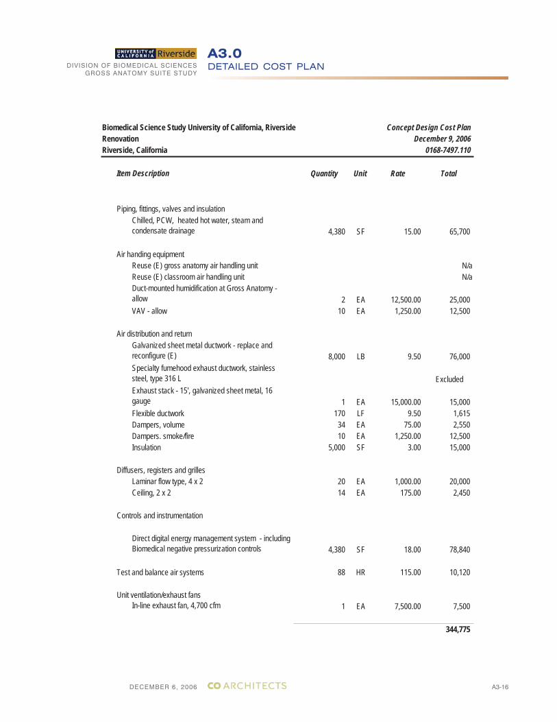
DECEMBER 6, 2006
DIVISION OF BIOMEDICAL SCIENCESGROSS ANATOMY SUITE STUDY
A3-16
DETAILED COST PLANA3.0
Biomedical Science Study University of California, Riverside Concept Design Cost PlanRenovation December 9, 2006Riverside, California 0168-7497.110
Item Description Quantity Unit Rate Total
Piping, fittings, valves and insulationChilled, PCW, heated hot water, steam andcondensate drainage 4,380 SF 15.00 65,700
Air handing equipmentReuse (E) gross anatomy air handling unit N/aReuse (E) classroom air handling unit N/aDuct-mounted humidification at Gross Anatomy - allow 2 EA 12,500.00 25,000VAV - allow 10 EA 1,250.00 12,500
Air distribution and returnGalvanized sheet metal ductwork - replace and reconfigure (E) 8,000 LB 9.50 76,000Specialty fumehood exhaust ductwork, stainless steel, type 316 L ExcludedExhaust stack - 15', galvanized sheet metal, 16 gauge 1 EA 15,000.00 15,000Flexible ductwork 170 LF 9.50 1,615Dampers, volume 34 EA 75.00 2,550Dampers. smoke/fire 10 EA 1,250.00 12,500Insulation 5,000 SF 3.00 15,000
Diffusers, registers and grillesLaminar flow type, 4 x 2 20 EA 1,000.00 20,000Ceiling, 2 x 2 14 EA 175.00 2,450
Controls and instrumentation
Direct digital energy management system - including Biomedical negative pressurization controls 4,380 SF 18.00 78,840
Test and balance air systems 88 HR 115.00 10,120
Unit ventilation/exhaust fansIn-line exhaust fan, 4,700 cfm 1 EA 7,500.00 7,500
344,775
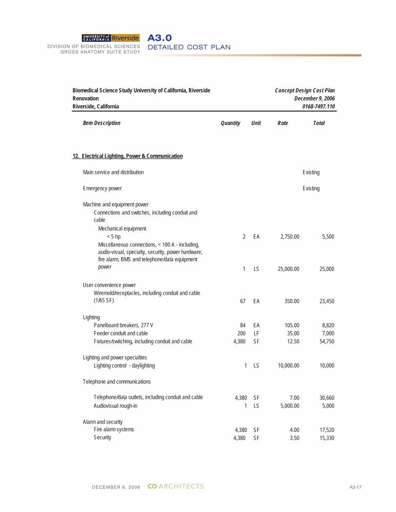
DECEMBER 6, 2006
DIVISION OF BIOMEDICAL SCIENCESGROSS ANATOMY SUITE STUDY
A3-17
DETAILED COST PLANA3.0
Biomedical Science Study University of California, Riverside Concept Design Cost PlanRenovation December 9, 2006Riverside, California 0168-7497.110
Item Description Quantity Unit Rate Total
12. Electrical Lighting, Power & Communication
Main service and distribution Existing
Emergency power Existing
Machine and equipment powerConnections and switches, including conduit and cable
Mechanical equipment < 5 hp 2 EA 2,750.00 5,500
Miscellaneous connections, < 100 A - including, audio-visual, specialty, security, power hardware, fire alarm, BMS and telephone/data equipment power 1 LS 25,000.00 25,000
User convenience powerWiremold/receptacles, including conduit and cable (1/65 SF) 67 EA 350.00 23,450
LightingPanelboard breakers, 277 V 84 EA 105.00 8,820Feeder conduit and cable 200 LF 35.00 7,000Fixtures/switching, including conduit and cable 4,380 SF 12.50 54,750
Lighting and power specialtiesLighting control - daylighting 1 LS 10,000.00 10,000
Telephone and communications
Telephone/data outlets, including conduit and cable 4,380 SF 7.00 30,660Audiovisual rough-in 1 LS 5,000.00 5,000
Alarm and securityFire alarm systems 4,380 SF 4.00 17,520Security 4,380 SF 3.50 15,330
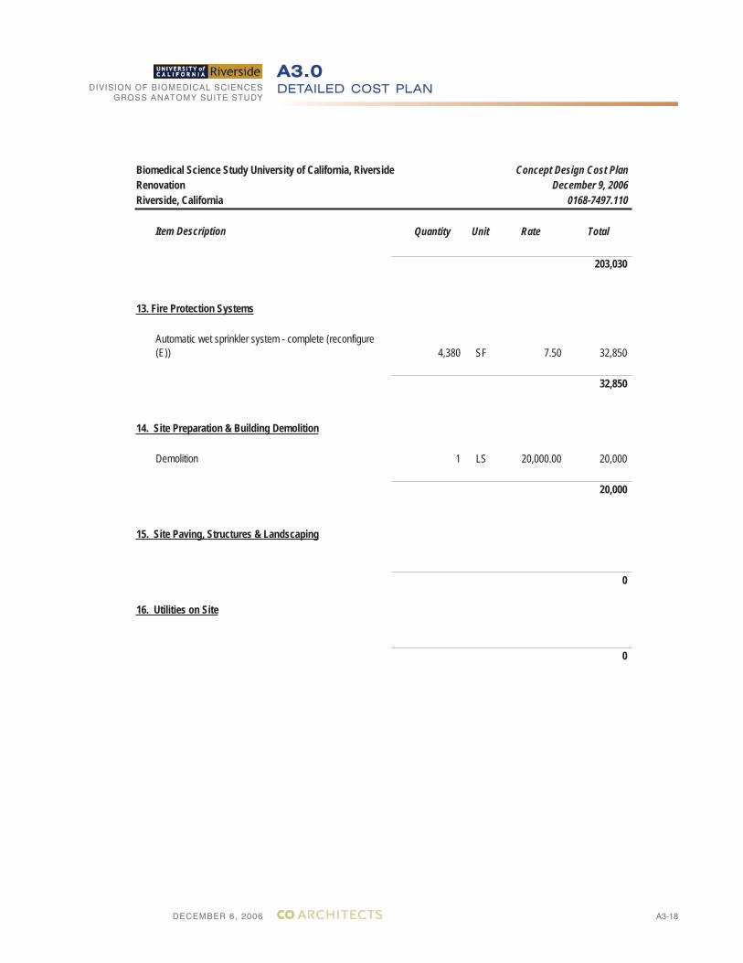
DECEMBER 6, 2006
DIVISION OF BIOMEDICAL SCIENCESGROSS ANATOMY SUITE STUDY
A3-18
DETAILED COST PLANA3.0
Biomedical Science Study University of California, Riverside Concept Design Cost PlanRenovation December 9, 2006Riverside, California 0168-7497.110
Item Description Quantity Unit Rate Total
203,030
13. Fire Protection Systems
4,380 SF 7.50 32,850
32,850
14. Site Preparation & Building Demolition
1 LS 20,000.00 20,000
20,000
15. Site Paving, Structures & Landscaping
0
16. Utilities on Site
0
Automatic wet sprinkler system - complete (reconfigure (E))
Demolition
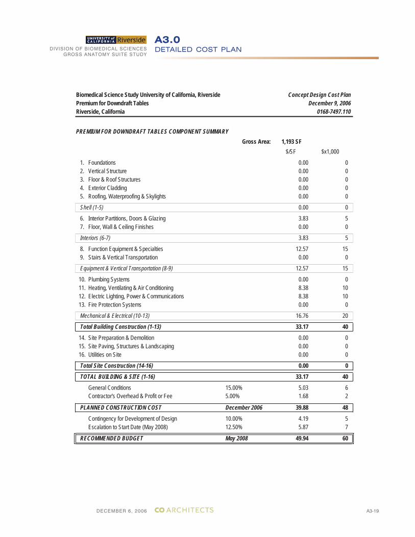
DECEMBER 6, 2006
DIVISION OF BIOMEDICAL SCIENCESGROSS ANATOMY SUITE STUDY
A3-19
DETAILED COST PLANA3.0
Biomedical Science Study University of California, Riverside Concept Design Cost PlanPremium for Downdraft Tables December 9, 2006Riverside, California 0168-7497.110
PREMIUM FOR DOWNDRAFT TABLES COMPONENT SUMMARYGross Area: 1,193 SF
$/SF $x1,000
1. Foundations 0.00 0 2. Vertical Structure 0.00 0 3. Floor & Roof Structures 0.00 0 4. Exterior Cladding 0.00 0 5. Roofing, Waterproofing & Skylights 0.00 0
Shell (1-5) 0.00 0
6. Interior Partitions, Doors & Glazing 3.83 5 7. Floor, Wall & Ceiling Finishes 0.00 0
Interiors (6-7) 3.83 5
8. Function Equipment & Specialties 12.57 15 9. Stairs & Vertical Transportation 0.00 0
Equipment & Vertical Transportation (8-9) 12.57 15
10. Plumbing Systems 0.00 0 11. Heating, Ventilating & Air Conditioning 8.38 10 12. Electric Lighting, Power & Communications 8.38 10 13. Fire Protection Systems 0.00 0
Mechanical & Electrical (10-13) 16.76 20
Total Building Construction (1-13) 33.17 40
14. Site Preparation & Demolition 0.00 0 15. Site Paving, Structures & Landscaping 0.00 0 16. Utilities on Site 0.00 0
Total Site Construction (14-16) 0.00 0
TOTAL BUILDING & SITE (1-16) 33.17 40
General Conditions 15.00% 5.03 6Contractor's Overhead & Profit or Fee 5.00% 1.68 2
PLANNED CONSTRUCTION COST December 2006 39.88 48
Contingency for Development of Design 10.00% 4.19 5Escalation to Start Date (May 2008) 12.50% 5.87 7
RECOMMENDED BUDGET May 2008 49.94 60
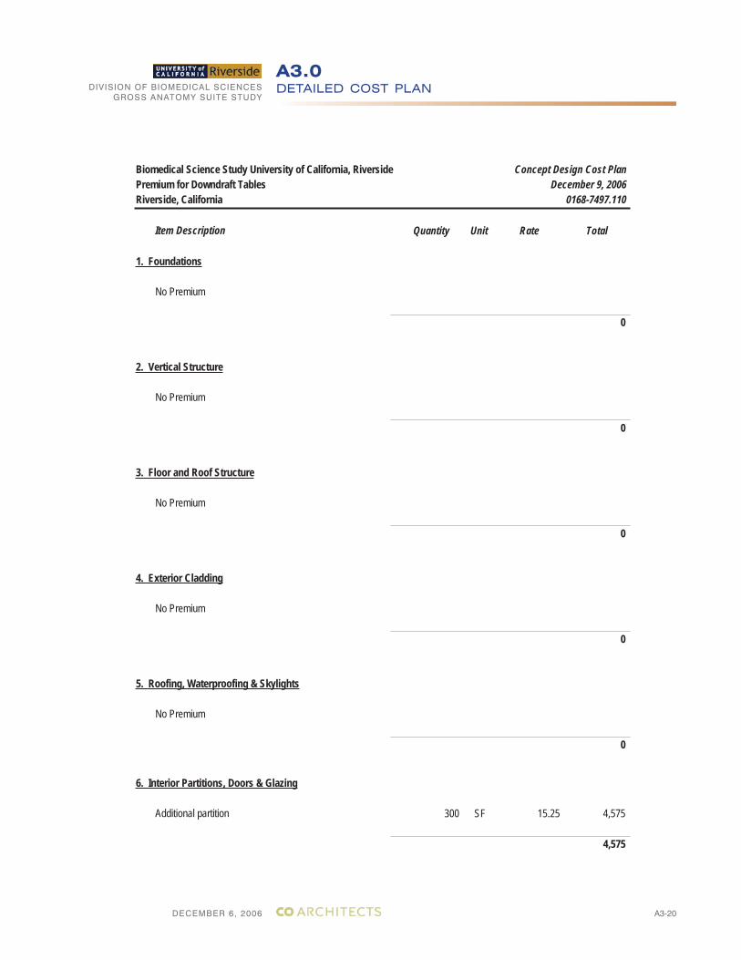
DECEMBER 6, 2006
DIVISION OF BIOMEDICAL SCIENCESGROSS ANATOMY SUITE STUDY
A3-20
DETAILED COST PLANA3.0
Biomedical Science Study University of California, Riverside Concept Design Cost PlanPremium for Downdraft Tables December 9, 2006Riverside, California 0168-7497.110
Item Description Quantity Unit Rate Total
1. Foundations
No Premium
0
2. Vertical Structure
No Premium
0
3. Floor and Roof Structure
No Premium
0
4. Exterior Cladding
No Premium
0
5. Roofing, Waterproofing & Skylights
No Premium
0
6. Interior Partitions, Doors & Glazing
Additional partition 300 SF 15.25 4,575
4,575
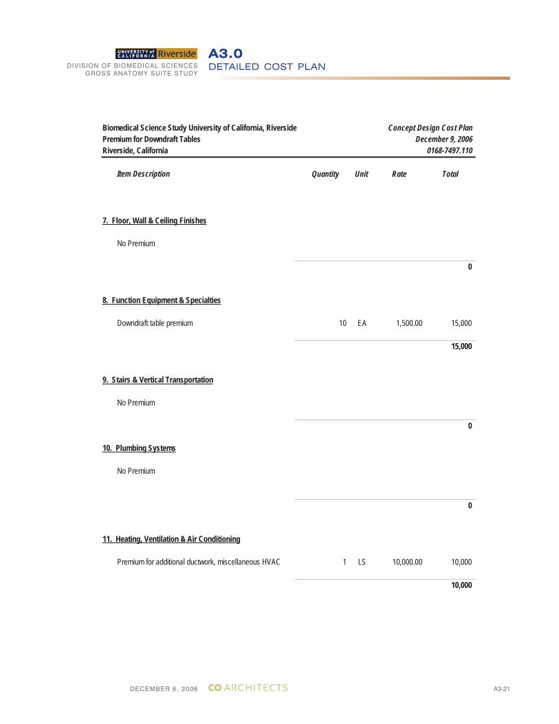
DECEMBER 6, 2006
DIVISION OF BIOMEDICAL SCIENCESGROSS ANATOMY SUITE STUDY
A3-21
DETAILED COST PLANA3.0
Biomedical Science Study University of California, Riverside Concept Design Cost PlanPremium for Downdraft Tables December 9, 2006Riverside, California 0168-7497.110
Item Description Quantity Unit Rate Total
7. Floor, Wall & Ceiling Finishes
No Premium
0
8. Function Equipment & Specialties
Downdraft table premium 10 EA 1,500.00 15,000
15,000
9. Stairs & Vertical Transportation
No Premium
0
10. Plumbing Systems
No Premium
0
11. Heating, Ventilation & Air Conditioning
Premium for additional ductwork, miscellaneous HVAC 1 LS 10,000.00 10,000
10,000
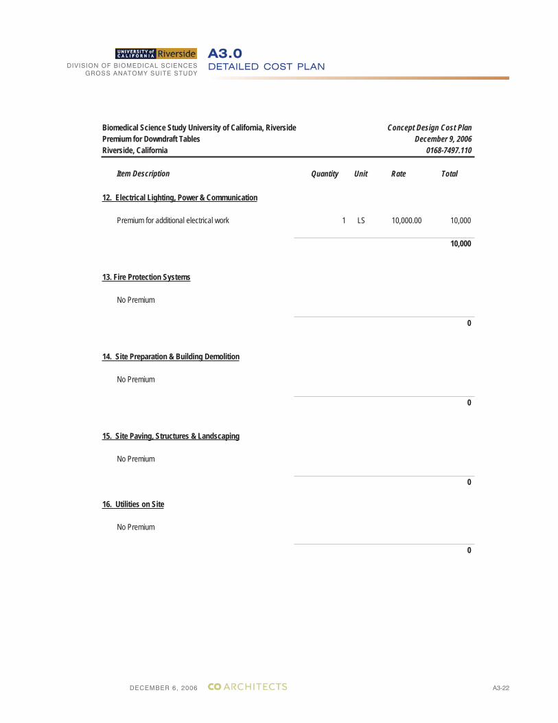
DECEMBER 6, 2006
DIVISION OF BIOMEDICAL SCIENCESGROSS ANATOMY SUITE STUDY
A3-22
DETAILED COST PLANA3.0
Biomedical Science Study University of California, Riverside Concept Design Cost PlanPremium for Downdraft Tables December 9, 2006Riverside, California 0168-7497.110
Item Description Quantity Unit Rate Total
12. Electrical Lighting, Power & Communication
Premium for additional electrical work 1 LS 10,000.00 10,000
10,000
13. Fire Protection Systems
No Premium
0
14. Site Preparation & Building Demolition
No Premium
0
15. Site Paving, Structures & Landscaping
No Premium
0
16. Utilities on Site
No Premium
0
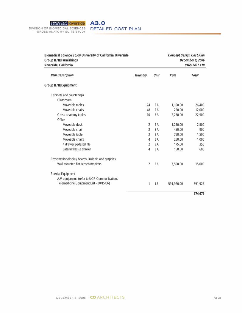
DECEMBER 6, 2006
DIVISION OF BIOMEDICAL SCIENCESGROSS ANATOMY SUITE STUDY
A3-23
DETAILED COST PLANA3.0
Biomedical Science Study University of California, Riverside Concept Design Cost PlanGroup II / III Furnishings December 9, 2006Riverside, California 0168-7497.110
Item Description Quantity Unit Rate Total
Group II / III Equipment
Cabinets and countertopsClassroom
Moveable tables 24 EA 1,100.00 26,400Moveable chairs 48 EA 250.00 12,000
Gross anatomy tables 10 EA 2,250.00 22,500Office
Moveable desk 2 EA 1,250.00 2,500Moveable chair 2 EA 450.00 900Moveable table 2 EA 750.00 1,500Moveable chairs 4 EA 250.00 1,0004 drawer pedestal file 2 EA 175.00 350Lateral files -2 drawer 4 EA 150.00 600
Presentation/display boards, insignia and graphicsWall mounted flat screen monitors 2 EA 7,500.00 15,000
Special EquipmentA/V equipment (refer to UCR Communications Telemedicine Equipment List - 08/15/06) 1 LS 591,926.00 591,926
674,676
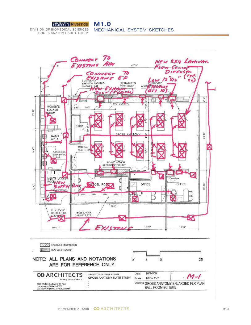
DECEMBER 6, 2006
DIVISION OF BIOMEDICAL SCIENCESGROSS ANATOMY SUITE STUDY
MECHANICAL SYSTEM SKETCHESM1.0
M1-1
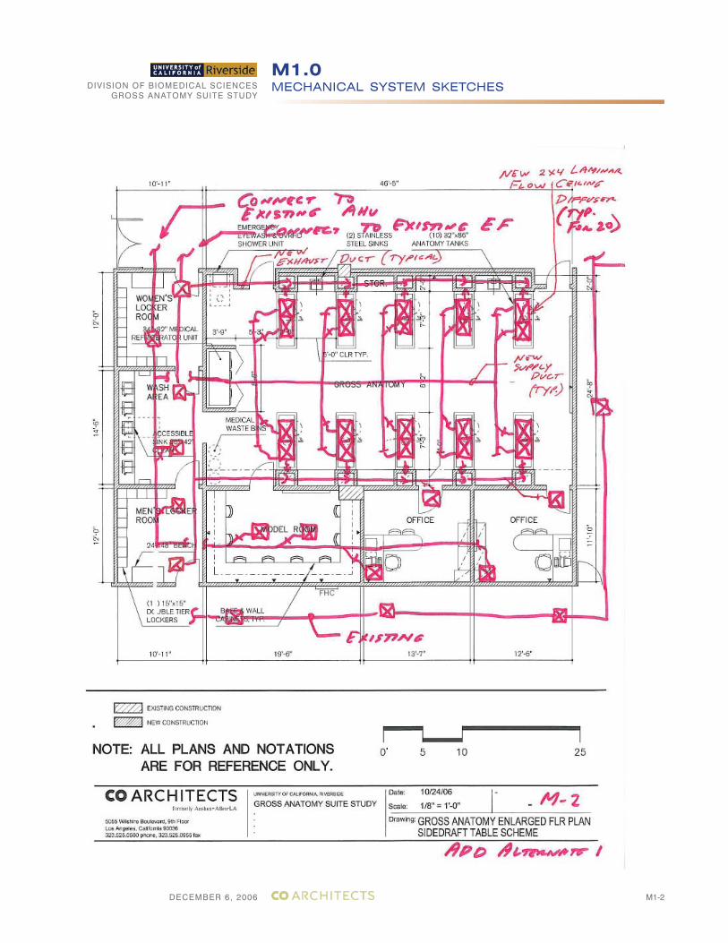
DECEMBER 6, 2006
DIVISION OF BIOMEDICAL SCIENCESGROSS ANATOMY SUITE STUDY
MECHANICAL SYSTEM SKETCHESM1.0
M1-2
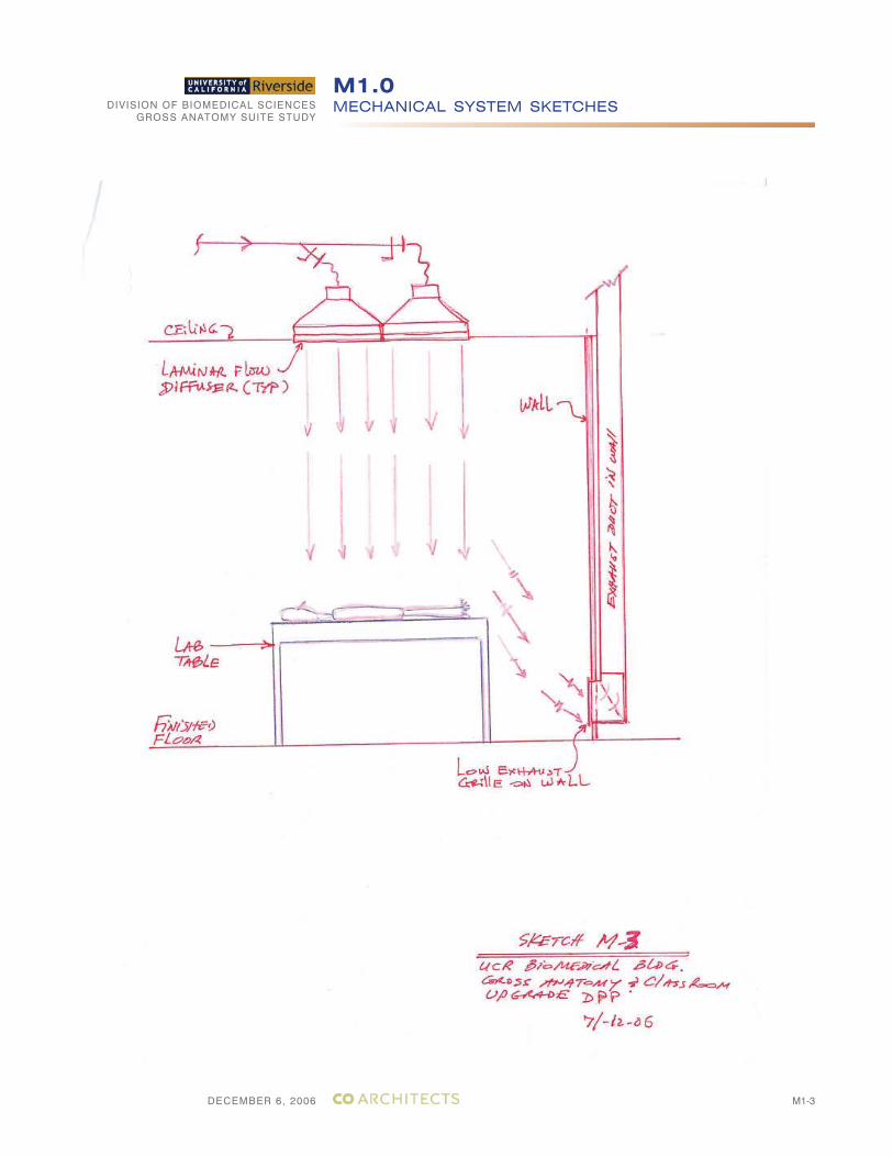
DECEMBER 6, 2006
DIVISION OF BIOMEDICAL SCIENCESGROSS ANATOMY SUITE STUDY
MECHANICAL SYSTEM SKETCHESM1.0
M1-3
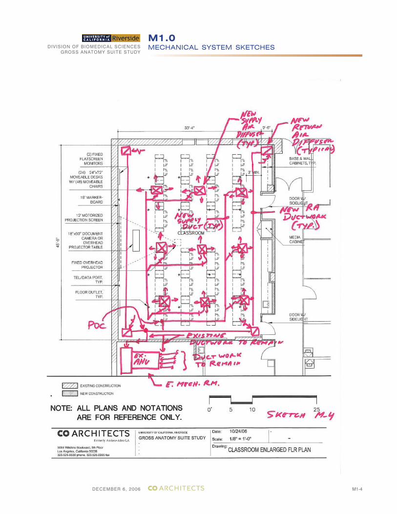
DECEMBER 6, 2006
DIVISION OF BIOMEDICAL SCIENCESGROSS ANATOMY SUITE STUDY
MECHANICAL SYSTEM SKETCHESM1.0
M1-4
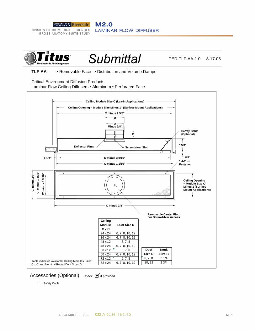
DECEMBER 6, 2006
DIVISION OF BIOMEDICAL SCIENCESGROSS ANATOMY SUITE STUDY
LAMINAR FLOW DIFFUSERM2.0
M2-1
TLF-AA • Removable Face • Distribution and Volume Damper
Critical Environment Diffusion Products Laminar Flow Ceiling Diffusers • Aluminum • Perforated Face
Table indicates Availablel Ceiling Modules Sizes C x C' and Nominal Round Duct Sizes D.
CED-TLF-AA-1.0 8-17-05
Ceiling Module Size C (Lay-In Applications)
Screwdriver Slot
Ceiling Opening = Module Size Minus 1" (Surface Mount Applications)
C' m
inus
1 1
/16"
C' m
inus
3/8
"
1 1/4"
C' m
inus
3 9
/16"
C minus 3 9/16"
C minus 1 1/16"
C minus 3/8"
Deflector Ring
B
DC minus 2 5/8"
Minus 1/8"D
Ceiling Opening= Module Size C'Minus 1 (Surface Mount Applications)
Removable Center Plug
3/8"
Fastener1/4-Turn
Safety Cable(Optional)
5 5/8"
Duct Size D
Neck Size B
6, 7, 8 2 1/410, 12 2 3/4
Ceiling Module C x C
Duct Size D
24 x 24 6, 7, 8, 10, 1236 x 24 6, 7, 8, 10, 1248 x 12 6, 7, 848 x 24 6, 7, 8, 10, 1260 x 12 6, 7, 860 x 24 6, 7, 8, 10, 1272 x 12 6, 7, 872 x 24 6, 7, 8, 10, 12
Accessories (Optional) Check if provided.
Safety Cable
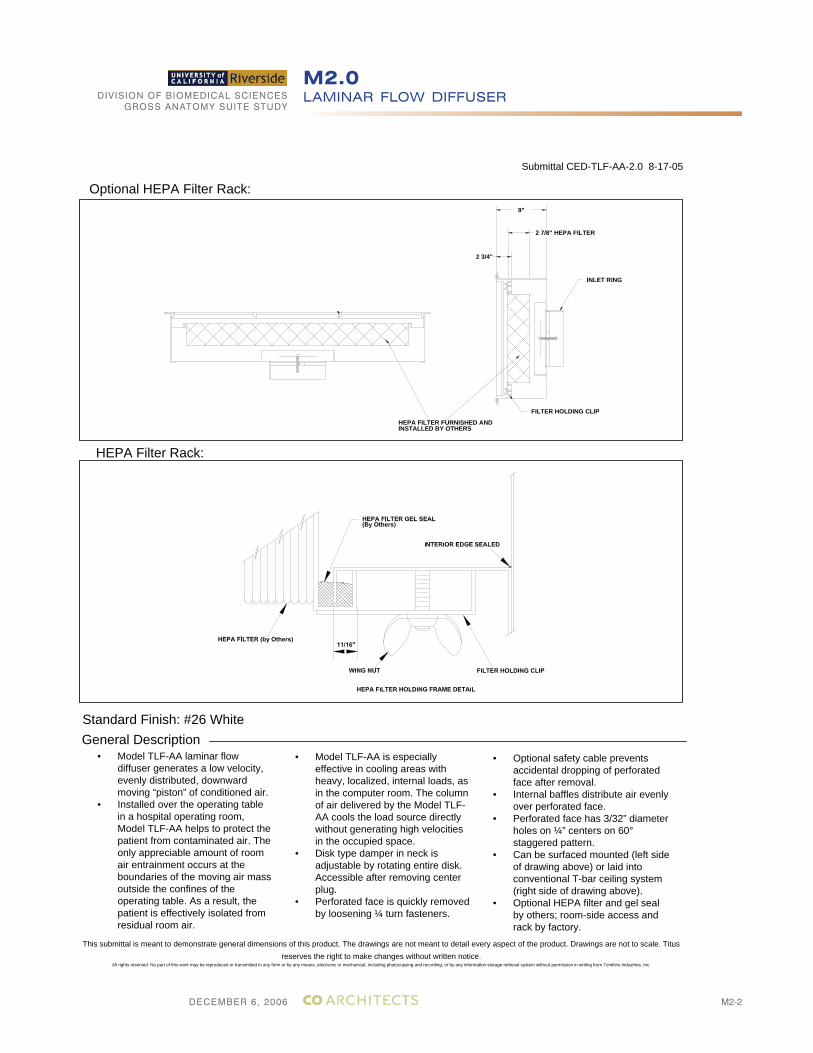
DECEMBER 6, 2006
DIVISION OF BIOMEDICAL SCIENCESGROSS ANATOMY SUITE STUDY
LAMINAR FLOW DIFFUSERM2.0
M2-2
Standard Finish: #26 WhiteGeneral Description
• Model TLF-AA laminar flow diffuser generates a low velocity, evenly distributed, downward moving “piston” of conditioned air.
• Installed over the operating table in a hospital operating room, Model TLF-AA helps to protect the patient from contaminated air. The only appreciable amount of room air entrainment occurs at the boundaries of the moving air mass outside the confines of the operating table. As a result, the patient is effectively isolated from residual room air.
This submittal is meant to demonstrate general dimensions of this product. The drawings are not meant to detail every aspect of the product. Drawings are not to scale. Titus reserves the right to make changes without written notice.
All rights reserved. No part of this work may be reproduced or transmitted in any form or by any means, electronic or mechanical, including photocopying and recording, or by any information storage retrieval system without permission in writing from Tomkins Industries, Inc.
• Model TLF-AA is especially effective in cooling areas with heavy, localized, internal loads, as in the computer room. The column of air delivered by the Model TLF-AA cools the load source directly without generating high velocities in the occupied space.
• Disk type damper in neck is adjustable by rotating entire disk. Accessible after removing center plug.
• Perforated face is quickly removed by loosening ¼ turn fasteners.
• Optional safety cable prevents accidental dropping of perforated face after removal.
• Internal baffles distribute air evenly over perforated face.
• Perforated face has 3/32” diameter holes on ¼” centers on 60° staggered pattern.
• Can be surfaced mounted (left side of drawing above) or laid into conventional T-bar ceiling system (right side of drawing above).
• Optional HEPA filter and gel seal by others; room-side access and rack by factory.
Submittal CED-TLF-AA-2.0 8-17-05
HEPA FILTER FURNISHED ANDINSTALLED BY OTHERS
FILTER HOLDING CLIP
INLET RING
2 3/4"
9"
2 7/8" HEPA FILTER
Optional HEPA Filter Rack:
HEPA Filter Rack:
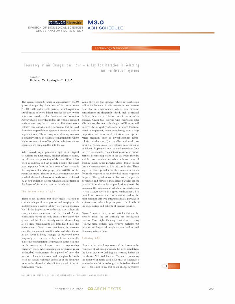
DECEMBER 6, 2006
DIVISION OF BIOMEDICAL SCIENCESGROSS ANATOMY SUITE STUDY
ACH SCHEDULEM3.0
M3-1
a report by
A i r i s t a r T e c h n o l o g i e s ™, L . L . C .
The average person breathes in approximately 16,000quarts of air per day. Each quart of air contains some70,000 visible and invisible particles, which equates toa total intake of over a billion particles per day. Whenit is then considered that Environmental ProtectionAgency studies show that indoor air within a standardenvironment may be as much as 100 times morepolluted than outside air, it is no wonder that the needfor indoor air purification systems is becoming such animportant topic. The necessity of air cleaning solutionsis especially critical in healthcare environments, wherehigher concentrations of harmful or infectious micro-organisms are being emitted into the air.
When considering air purification systems, it is typicalto evaluate the filter media, product efficiency claims,and the size and portability of the unit. What is lessoften considered, and yet is quite possibly the singlemost important factor in the success of any system, isthe frequency of air changes per hour (ACH) that thesystem can create. The rate of ACH determines the rateat which the total volume of air in the room is cleanedby an air purification system, which is a major factor inthe degree of air cleaning that can be achieved.
T h e Impo r t a n c e o f A CH
There is no question that filter media selection iscritical to the purification process, and also plays a rolein determining a system’s ability to create air changes,but it is also important to understand that without airchanges indoor air cannot truly be cleaned. An airpurification system can only clean air that enters thesystem, and the filtered air only remains clean as longas no new contaminants are introduced into theenvironment. Given these conditions, it becomesclear that the greatest benefit is achieved when the airin the room is being changed or processed morefrequently, as clean air is then able to continuallydilute the concentration of unwanted particles in theair. In essence, air changes create a compoundingefficiency effect. After operating an air purifier in anundisturbed environment for a period of time, thetotal air volume in the room will be replenished withclean air, which eventually allows all of the air in theroom to be cleaned to the efficiency level of the airpurification system.
While there are few instances where air purificationwill be implemented in this manner, it does becomeclear that in environments where new airbornecontaminants are frequently added, such as medicalfacilities, there is a need for increased frequency of airchanges. Given two systems with equivalent filtereffectiveness, the unit with a higher ACH rating willimprove the air quality of a room in much less time,which is important, when considering how a largeproportion of nosocomial infections are spread.Micro-organisms such as mycobacterium tuber-culosis, measles virus (i.e. rubella), and small poxvirus (i.e. variola major) are released into the air asindividual droplets via oral or nasal secretions frominfected individuals. These infectious airborne diseaseparticles become suspended in the air, where they dryand become attached to other airborne materialcreating much larger particles called droplet nucleithat are between one and five microns in size. Theselarger infectious particles can then remain in the airfor much longer than the individual micro-organismdroplets. The good news is that with proper aircirculation and filtration these larger particles can beremoved from the air by air purification systems. Byincreasing the frequency in which an air purificationsystem changes the air in a given environment, it ispossible to decrease the concentration level of themost common airborne infectious disease particles ina given space, which helps to protect the health ofthe staff, visitors and patients of medical facilities.
Figure 1 depicts the types of particles that can becleaned from the air utilising air purificationsystems. Most high efficiency particulate arresting(HEPA)-rated systems can remove particles 0.3microns or larger, although system airflow andefficiency ratings vary.
De f i n i n g A CH
Now that the critical importance of air changes to thereduction of airborne particulate has been established,the focus moves to defining and creating indoor aircirculation. ACH is defined as, “A value representingthe number of times each hour that an enclosure’stotal volume of air is exchanged with fresh or filteredair.”1 This is not to say that an air change represents
Frequency o f A i r Changes per Hour – A Key Cons iderat ion in Se lec t ingA i r Pur i f i ca t ion Sys tems
B U S I N E S S B R I E F I N G : H O S P I T A L E N G I N E E R I N G & F A C I L I T I E S M A N A G E M E N T 2 0 0 5
1
Technology & Services
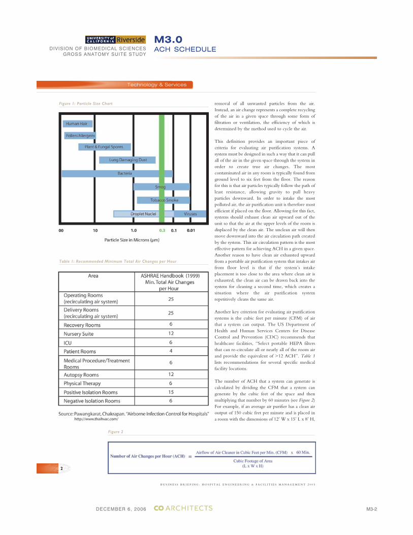
DECEMBER 6, 2006
DIVISION OF BIOMEDICAL SCIENCESGROSS ANATOMY SUITE STUDY
ACH SCHEDULEM3.0
M3-2
removal of all unwanted particles from the air.Instead, an air change represents a complete recyclingof the air in a given space through some form offiltration or ventilation, the efficiency of which isdetermined by the method used to cycle the air.
This definition provides an important piece ofcriteria for evaluating air purification systems. Asystem must be designed in such a way that it can pullall of the air in the given space through the system inorder to create true air changes. The mostcontaminated air in any room is typically found fromground level to six feet from the floor. The reasonfor this is that air particles typically follow the path ofleast resistance, allowing gravity to pull heavyparticles downward. In order to intake the mostpolluted air, the air purification unit is therefore mostefficient if placed on the floor. Allowing for this fact,systems should exhaust clean air upward out of theunit so that the air at the upper levels of the room isdisplaced by the clean air. The unclean air will thenmove downward into the air circulation path createdby the system. This air circulation pattern is the mosteffective pattern for achieving ACH in a given space.Another reason to have clean air exhausted upwardfrom a portable air purification system that intakes airfrom floor level is that if the system’s intakeplacement is too close to the area where clean air isexhausted, the clean air can be drawn back into thesystem for cleaning a second time, which creates asituation where the air purification systemrepetitively cleans the same air.
Another key criterion for evaluating air purificationsystems is the cubic feet per minute (CFM) of airthat a system can output. The US Department ofHealth and Human Services Centers for DiseaseControl and Prevention (CDC) recommends thathealthcare facilities, “Select portable HEPA filtersthat can re-circulate all or nearly all of the room airand provide the equivalent of >12 ACH”. Table 1lists recommendations for several specific medicalfacility locations.
The number of ACH that a system can generate iscalculated by dividing the CFM that a system cangenerate by the cubic feet of the space and thenmultiplying that number by 60 minutes (see Figure 2)For example, if an average air purifier has a clean airoutput of 150 cubic feet per minute and is placed ina room with the dimensions of 12’ W x 15’ L x 8’ H,
B U S I N E S S B R I E F I N G : H O S P I T A L E N G I N E E R I N G & F A C I L I T I E S M A N A G E M E N T 2 0 0 5
2
Technology & Services
Figure 1: Particle Size Chart
Table 1: Recommended Minimum Total Air Changes per Hour
Figure 2
DECEMBER 6, 2006
DIVISION OF BIOMEDICAL SCIENCESGROSS ANATOMY SUITE STUDY
ACH SCHEDULEM3.0
M3-3
Frequency o f ACH – A Key Cons iderat ion in Se lec t ing A i r Pur i f i ca t ion Sys tems
the unit needs to clean 1,440 cubic feet of air.Utilising the formula, it is determined that the unitwill complete six ACH or roughly one air changeevery 10 minutes. In order to meet the CDCrecommendation within this sample space, thesystem selected has to have a total clean air output of300 CFM, which could be met by selecting a singleunit that can produce 300 CFM or placing two unitsin the space.
I n c r e a s i n g t h e F r e q u e n c y o f A CH
Thus far, the basic principles of ACH have beenexplored; and several simple ways to evaluate airpurification systems in terms of the ability to circulatethe air in a given space have been discussed. What isof more interest are the ways in which airpurification systems can be designed to create greaterairflow and thereby increase the frequency of ACHthat a single unit can provide. There are a number ofdesign factors that determine the CFM and ACH asystem can output. The most important factor is theselection and placement of filters within the system.As stated previously, the CDC recommends the useof HEPA filtration in medical environments in orderto clean the air.
HEPA filtration technology was designed duringWorld War II (WWII) by the Atomic EnergyCommission to remove and capture radioactivedust particles in order to protect the humanrespiratory system. HEPA filters are rated to removeup to 99.97% of all particles 0.3 microns in size orlarger, which encompasses most non-viral airborneparticles. HEPA filter media also has importantefficiency properties that are critical to successful airpurification solutions. Not only is the filter mediaefficient at cleaning the air that passes through thefilter, but it is designed in such a way that asparticles are captured on the surface of the filter thecleaning efficiency of the filter actually increasesbefore eventually decreasing as the filter becomesfilled with particulates.
There is also a new type of filter media called highairflow particulate arresting (HAPATM) that furtherimproves on HEPA technology and can helpsystems achieve increased air circulation. Like its
WWII-era predecessor, HAPA is also rated toremove up to 99.97% of all particles 0.3 microns insize or larger. This filter media is constructed of atotally synthetic melt blown fibre material that ismore durable than traditional HEPA filters. It hasalso shown greater depth loading capacity2 thanHEPA-rated filter material, which means that moreparticles can collect on the filter surface before theefficiency of the filter begins to decrease. Mostimportantly, HAPA is less restrictive to airflow thanHEPA, which means that systems utilising HAPAfilter media are capable of achieving higher CFMoutput than systems utilising HEPA filtration.
Once the filter media is selected, the placement ofthe filters, both in terms of filter order and spacingwithin the system, must be considered as both factorscontribute to the level of CFM that a unit canproduce. There is no way to define the correctdesign of an air purification system, but evaluatingthe way in which airflow is created and restricted bythe filter media is one way to better understand theACH and the efficiency that can be achieved withthe unit. The one known truth about filterplacement is that the presence of pre-filters within airpurification systems is critical to protecting theefficiency of the system. By removing larger particlesfrom the air before the air is cycled through theHEPA or HAPA filter media, higher airflow levelscan be maintained for longer periods of time.
S e l e c t i n g t h e R i g h t A i r P u r i f i c a t i o n S y s t em
Creating a clean and safe indoor environment is acomplex task. Selecting the correct air purificationsystem is an integral part of this task, and requires acomplete understanding of both the environment andthe required results. The CDC recommends thathealthcare facilities, “Situate portable HEPA units withthe advice of facility engineers to ensure that all roomair is filtered”. Regardless of the process followed toevaluate an air purification system, one thing is clear.Creating ACH is the key to providing a clean airenvironment. Systems that can provide therecommended frequency of ACH for a medical facilitywill exponentially improve the quality of the air that isshared by the facility’s patients, visitors and staff. ■
B U S I N E S S B R I E F I N G : H O S P I T A L E N G I N E E R I N G & F A C I L I T I E S M A N A G E M E N T 2 0 0 5
3
1. www.energyvortex.com2. based on recent testing completed by the manufacturer.