Embed Size (px)
Citation preview
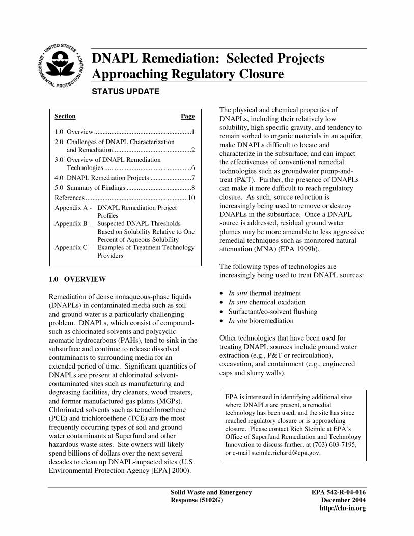
STATUS UPDATE
Section Page
1.0 Overview .........................................................1
2.0 Challenges of DNAPL Characterization and Remediation..............................................2
3.0 Overview of DNAPL Remediation Technologies ...................................................6
4.0 DNAPL Remediation Projects ........................7
5.0 Summary of Findings ......................................8
References ............................................................10
Appendix A DNAPL Remediation Project Profiles
Appendix B Suspected DNAPL Thresholds Based on Solubility Relative to One Percent of Aqueous Solubility
Appendix C Examples of Treatment Technology Providers
1.0 OVERVIEW
Remediation of dense nonaqueous-phase liquids (DNAPLs) in contaminated media such as soil and ground water is a particularly challenging problem. DNAPLs, which consist of compounds such as chlorinated solvents and polycyclic aromatic hydrocarbons (PAHs), tend to sink in the subsurface and continue to release dissolved contaminants to surrounding media for an extended period of time. Significant quantities of DNAPLs are present at chlorinated solvent-contaminated sites such as manufacturing and degreasing facilities, dry cleaners, wood treaters, and former manufactured gas plants (MGPs). Chlorinated solvents such as tetrachloroethene (PCE) and trichloroethene (TCE) are the most frequently occurring types of soil and ground water contaminants at Superfund and other hazardous waste sites. Site owners will likely spend billions of dollars over the next several decades to clean up DNAPL-impacted sites (U.S. Environmental Protection Agency [EPA] 2000).
DNAPL Remediation: Selected Projects Approaching Regulatory Closure
The physical and chemical properties of DNAPLs, including their relatively low solubility, high specific gravity, and tendency to remain sorbed to organic materials in an aquifer, make DNAPLs difficult to locate and characterize in the subsurface, and can impact the effectiveness of conventional remedial technologies such as groundwater pump-and-treat (P&T). Further, the presence of DNAPLs can make it more difficult to reach regulatory closure. As such, source reduction is increasingly being used to remove or destroy DNAPLs in the subsurface. Once a DNAPL source is addressed, residual ground water plumes may be more amenable to less aggressive remedial techniques such as monitored natural attenuation (MNA) (EPA 1999b).
The following types of technologies are increasingly being used to treat DNAPL sources:
• In situ thermal treatment • In situ chemical oxidation • Surfactant/co-solvent flushing • In situ bioremediation
Other technologies that have been used for treating DNAPL sources include ground water extraction (e.g., P&T or recirculation), excavation, and containment (e.g., engineered caps and slurry walls).
EPA is interested in identifying additional sites where DNAPLs are present, a remedial technology has been used, and the site has since reached regulatory closure or is approaching closure. Please contact Rich Steimle at EPA’s Office of Superfund Remediation and Technology Innovation to discuss further, at (703) 603-7195, or e-mail [email protected].
Solid Waste and Emergency EPA 542-R-04-016 Response (5102G) December 2004
http://clu-in.org
DNAPL Remediation: Selected Projects Approaching Regulatory Closure
This paper is a status update on the use of DNAPL source reduction remedial technologies, and provides information about recent projects where regulatory closure has been reached or projects that are approaching regulatory closure, following source reduction. Information is presented about the challenges associated with DNAPL remediation, the types of in situ technologies used, and data and findings concerning the relative effectiveness of field applications of these technologies. Appendix A contains project profiles for eight field applications that illustrate some of the findings presented in this paper.
This paper is intended for use by project managers, federal and state regulatory staff, site owners, consultants, and technology providers. It provides current information about selected experiences with the technologies mentioned above. Users of this paper are expected to have a basic understanding of site remediation approaches and terminology and are referred to the references cited in this paper for further information about specific remedial technologies. Mention of trade names or commercial products does not constitute endorsement or recommendation for use.
All the projects highlighted in this paper are practical examples of the use of in situ technologies to remediate DNAPL-impacted sites in order to achieve or partially achieve regulatory requirements. Most of these sites were not research test sites and did not involve direct measurement of DNAPL quantity. For this reason, significant uncertainties exist regarding how the treatment of the DNAPL sources affected the dissolved plumes. There currently is no consensus among remediation professionals about when source reduction should be recommended over containment. It is expected that over the next few years, more applications of aggressive source treatment technologies will be completed. Information from these applications will be helpful in further understanding how best to address the challenge of DNAPL contamination.
Demonstration programs for DNAPL remediation technologies have been performed or are ongoing at several national test center sites such as Dover Air Force Base, Delaware, and Cape Canaveral, Florida. Further information about these programs and specific test results are available from the following sources:
• Federal Remediation Technologies Roundtable (FRTR) (http://www.frtr.gov)
• Environmental Security Technology Certification Program (ESTCP) (http://www.estcp.org)
• Strategic Environmental Research and Development Program (SERDP) (http://www.serdp.org)
• Interagency DNAPL Consortium (http://www.getf.org/dnaplguest)
2.0 CHALLENGES OF DNAPL CHARACTERIZATION AND REMEDIATION
As discussed above, the physical and chemical properties of DNAPLs pose challenges in the characterization and remediation of this contaminant in the subsurface. The following discussion provides additional detail about the key challenges of treating DNAPLs that can affect the ability of a site to reach regulatory closure.
Locating and Verifying the Presence of DNAPLs – DNAPL source zones are often difficult to locate, and the size and spatial distribution of the source zone are difficult to determine, especially for complex scenarios such as sites with large contaminant masses in complex environments (for example, heterogeneous or fractured bedrock environments). With DNAPL characterization, it is important to have accurate site characterization and conceptual site models. Techniques that have been effective in locating and characterizing DNAPLs include surface geophysics, direct-push sampling (sometimes incorporating fluorescence sensors), membrane interface probes, or partition well interface testing (Kram and others 2001).
December 2004 2
DNAPL Remediation: Selected Projects Approaching Regulatory Closure
/ / ):
•
•
•
j
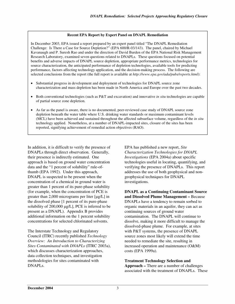
Recent EPA Report by Expert Panel on DNAPL Remediation
In December 2003, EPA issued a report prepared by an expert panel titled “The DNAPL Remediation Challenge: Is There a Case for Source Depletion?” (EPA 600/R-03/143). The panel, chaired by Michael Kavanaugh and P. Suresh Rao and under the direction of David Burden of the EPA National Risk Management Research Laboratory, examined seven questions related to DNAPLs. These questions focused on potential benefits and adverse impacts of DNAPL source depletion, appropriate performance metrics, technologies for source characterization, the anticipated performance of depletion technologies, available tools for predicting performance, factors affecting technology application, and the decision-making process. The following are selected conclusions from the report (the full report is available at http:/ www.epa.gov/ada/pubs reports.html
Substantial progress in development and deployment of technologies for DNAPL source zone characterization and mass depletion has been made in North America and Europe over the past two decades.
Both conventional technologies (such as P&T and excavation) and innovative in situ technologies are capable of partial source zone depletion.
As far as the panel is aware, there is no documented, peer-reviewed case study of DNAPL source zone depletion beneath the water table where U.S. drinking water standards or maximum contaminant levels (MCL) have been achieved and sustained throughout the affected subsurface volume, regardless of the in situ technology applied. Nonetheless, at a number of DNAPL-impacted sites, closure of the sites has been reported, signifying achievement of remedial action ob ectives (RAO).
In addition, it is difficult to verify the presence of DNAPLs through direct observation. Generally, their presence is indirectly estimated. One approach is based on ground water concentration data and the “1 percent of solubility” rule-of-thumb (EPA 1992). Under this approach, DNAPL is suspected to be present when the concentration of a chemical in ground water is greater than 1 percent of its pure-phase solubility (for example, when the concentration of PCE is greater than 2,000 micrograms per liter [µg/L] in the dissolved phase [1 percent of its pure-phase solubility of 200,000 µg/L], PCE is inferred to be present as a DNAPL). Appendix B provides additional information on the 1 percent solubility concentrations for selected chlorinated solvents.
The Interstate Technology and Regulatory Council (ITRC) recently published Technology Overview: An Introduction to Characterizing Sites Contaminated with DNAPLs (ITRC 2003a), which discusses characterization approaches, data collection techniques, and investigation methodologies for sites contaminated with DNAPLs.
EPA has published a new report, Site Characterization Technologies for DNAPL Investigations (EPA 2004a) about specific technologies useful in locating, quantifying, and verifying the presence of DNAPLs. This report addresses the use of both geophysical and non-geophysical techniques for DNAPL investigations.
DNAPL as a Continuing Contaminant Source and Dissolved Plume Management – Because DNAPLs have a tendency to remain sorbed to organic materials in an aquifer, they can act as continuing sources of ground water contamination. The DNAPL will continue to dissolve, making it more difficult to manage the dissolved-phase plume. For example, at sites with P&T systems, the presence of DNAPL source zones most likely will extend the time needed to remediate the site, resulting in increased operation and maintenance (O&M) costs (EPA 1999a).
Treatment Technology Selection and Approach – There are a number of challenges associated with the treatment of DNAPLs. These
December 2004 3
DNAPL Remediation: Selected Projects Approaching Regulatory Closure
include the effectiveness of partial source removal; uncertainties in the location and quantity of DNAPL in the subsurface; limited availability of performance and cost data for using innovative technologies to treat DNAPLs; and uncertainties about the long-term effectiveness of DNAPL source reduction. There is an ongoing debate within the remediation community regarding the utility of partial source removal or reduction, where some but not all of the DNAPL source is removed or destroyed. Although EPA policy generally supports active attention to sources (EPA 1993, 1999b, 2002), the published results of modeling and/or laboratory-scale column studies suggest that almost all DNAPL must be removed before site risks are significantly reduced, at least in the short term (Freeze and McWhorter 1997; Sale and McWhorter 2001). A recent report issued by the National Academy of Sciences emphasizes the need to perform site-specific analyses of the effectiveness of partial source reduction in order to better guide and justify remedy selection (National Research Council 2003). ITRC also published a recent report, Strategies for Monitoring the Performance of DNAPL Source Zone Remedies (DNAPLs-5) (ITRC 2004). This report describes approaches to performance monitoring while implementing various in situ remedial technologies for DNAPL treatment.
Because of uncertainties about the volume and distribution of DNAPLs and limited cost and performance data, project managers often do not select innovative in situ technologies. In addition, innovative technologies are often presumed to have higher costs than conventional systems such as P&T. Remediation professionals often compare costs for an innovative technology to that for a conventional technology based on the life-cycle costs. Life-cycle costs include the up-front cost for construction as well as the cost for O&M over the expected duration of the remediation. Net present value calculations are also typically incorporated into life-cycle cost estimation to factor in the time-value of money. Although the construction cost for an innovative technology may be higher than that for a traditional technology, the costs for O&M over the life of
the remediation may be lower, depending on the system’s scale and design. These lower lifetime O&M costs may offset the higher up-front costs for an innovative technology. Factors affecting O&M costs include the frequency and level of maintenance and the length of time for remedial system operation. With some conventional technologies like P&T, O&M costs might include the costs associated with routine maintenance, such as replacement of pumps and valves, as well as longer-term maintenance issues, such as replacement of extraction wells over the life of the extraction system and the maintenance, waste disposal, and power requirements for the treatment system.
Variation in Cleanup Levels and Closure Criteria – At sites contaminated with DNAPL, there is variation in the cleanup levels and closure criteria, including a wide range of quantitative goals as well as goals that specify qualitative objectives only, as shown below.
Examples of remedial action objectives established as qualitative criteria
“Clean up of ground water to the extent practicable for the source area”
“Removal of the source area, followed by natural attenuation”
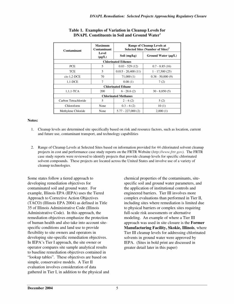
Table 1 illustrates variation in site-specific cleanup levels (for 44 sites across the country) for soil and groundwater contaminated with DNAPL constituents. As shown in this table, cleanup levels for individual chlorinated solvents have varied by as much as five orders of magnitude.
December 2004 4
DNAPL Remediation: Selected Projects Approaching Regulatory Closure
Table 1. Examples of Variation in Cleanup Levels for DNAPL Constituents in Soil and Ground Water1
Contaminant
Maximum Contaminant
Level (µg/L)
Range of Cleanup Levels at Selected Sites (Number of Sites)2
Soil (mg/kg) Ground Water (µg/L)
Chlorinated Ethenes PCE 5 0.03 - 529 (12) 0.7 - 8.85 (16)
TCE 5 0.015 - 20,400 (11) 1 - 17,500 (25)
cis-1,2-DCE 70 71,000 (1) 0.38 - 50,000 (9)
1,1-DCE 7 0.08 (1) 7 (2)
Chlorinated Ethane 1,1,1-TCA 200 6 - 28.6 (2) 30 - 8,850 (5)
Chlorinated Methanes Carbon Tetrachloride 5 2 – 6 (2) 5 (2)
Chloroform None 0.3 – 6 (2) 10 (1)
Methylene Chloride None 5.77 - 227,000 (2) 2,000 (1)
Notes:
1. Cleanup levels are determined site specifically based on risk and resource factors, such as location, current and future use, contaminant transport, and technology capabilities
2. Range of Cleanup Levels at Selected Sites based on information provided for 44 chlorinated solvent cleanup projects in cost and performance case study reports on the FRTR Website (http://www.frtr.gov). The FRTR case study reports were reviewed to identify projects that provide cleanup levels for specific chlorinated solvent compounds. These projects are located across the United States and involve use of a variety of cleanup technologies.
Some states follow a tiered approach to developing remediation objectives for contaminated soil and ground water. For example, Illinois EPA (IEPA) uses the Tiered Approach to Corrective Action Objectives (TACO) (Illinois EPA 2004) as defined in Title 35 of Illinois Administrative Code (Illinois Administrative Code). In this approach, the remediation objectives emphasize the protection of human health and also take into account site-specific conditions and land use to provide flexibility to site owners and operators in developing site-specific remediation objectives. In IEPA’s Tier I approach, the site owner or operator compares site sample analytical results to baseline remediation objectives contained in “lookup tables”. These objectives are based on simple, conservative models. A Tier II evaluation involves consideration of data gathered in Tier I, in addition to the physical and
chemical properties of the contaminants, site-specific soil and ground water parameters, and the application of institutional controls and engineered barriers. Tier III involves more complex evaluations than performed in Tier II, including sites where remediation is limited due to physical barriers or complex sites requiring full-scale risk assessments or alternative modeling. An example of where a Tier III approach was used in site closure is the Former Manufacturing Facility, Skokie, Illinois, where Tier III cleanup levels for addressing chlorinated solvents in ground water were approved by IEPA. (Sites in bold print are discussed in greater detail later in this paper)
December 2004 5
DNAPL Remediation: Selected Projects Approaching Regulatory Closure
Other examples of the tiered approach closure criteria being used at the sites that received closure letters include Texas Tier I Protective Concentration Levels (PCLs) in soil and Tier I commercial/industrial Class 3 risk-based exposure levels for TCE and PCE in ground water (Parkwood Former Dry Cleaner, Texas), and Indiana Tier II cleanup goals for industrial land use (Confidential Chemical Manufacturing Facility, Portland, Indiana).
3.0 OVERVIEW OF DNAPL REMEDIATION TECHNOLOGIES
This section provides an overview of selected technologies that have been used to treat DNAPL sources. Individual project profiles presented in Appendix A document the use of these in situ technologies as well as P&T and excavation. Examples of service providers for these technologies are identified in Appendix C. Additional information about in situ treatment technologies is available in the sources cited below and in the FRTR compilation of remediation technology assessment reports (http://www.frtr.gov/multisitereports.htm).
Several engineering considerations are associated with the applications of these technologies. For example, before the application of in situ thermal treatment, issues to be considered include potential migration of mobilized contaminants, health and safety issues associated with high temperatures and pressures, and potential thermal impacts on regional ground water. For the application of in situ chemical oxidation, it is important to consider the health and safety issues associated with chemical oxidants such as ozone, which can cause severe burns.
In Situ Thermal Treatment – This includes technologies that employ heat in the source zone to volatilize or mobilize DNAPL. Various approaches have been used, including steam injection (also referred to as steam-enhanced extraction, or SEE), electrical resistive heating (ERH; one variation of ERH is referred to as six-phase heating, or SPH), thermal conductive heating (also referred to as in situ thermal desorption, or ISTD), hot water injection, hot air
injection, and radio frequency (RF)-heating. In some applications, high temperature conditions have been created that destroy DNAPLs in place through pyrolysis. In situ thermal treatment technologies are described in more detail in In Situ Thermal Treatment of Chlorinated Solvents: Fundamentals and Field Applications (EPA 2004).
In Situ Chemical Oxidation – This includes technologies that involve injecting chemical oxidants or other amendments directly into the source zone to destroy DNAPL constituents in place. Three of the more common chemical oxidants used for DNAPL treatment are permanganate (either sodium or potassium permanganate), hydrogen peroxide (when used with iron catalysts, this is generally referred to as Fenton’s chemistry or Fenton’s reagent), and ozone. The injected oxidants react with the contaminant, breaking chemical bonds and producing degradation products such as carbon dioxide, water, and chloride. In situ chemical oxidation is described in greater detail in Technical and Regulatory Guidance for In Situ Chemical Oxidation of Contaminated Soil and Ground Water (ITRC 2001) and Technology Status Review: In Situ Oxidation (ESTCP 1999).
Surfactant/Co-solvent Flushing – This includes technologies that enhance DNAPL removal through injection and subsequent extraction of chemicals to solubilize and/or mobilize DNAPL constituents. The chemicals typically used are aqueous surfactant solutions, co-solvents that lower the interfacial tension (including alcohols such as ethanol or isopropyl alcohol), or electrolytes that aid in contaminant solubilization. The chemicals are injected into a system of wells designed to “sweep” the DNAPL zone within the aquifer. The chemical “flood” and the solubilized or mobilized DNAPL are extracted from the subsurface and are separated and treated aboveground. Surfactant/co-solvent flushing technology is described in greater detail in Technical and Regulatory Guidance for Surfactant/Co-solvent Flushing of DNAPL Source Zones (ITRC 2003b).
December 2004 6
DNAPL Remediation: Selected Projects Approaching Regulatory Closure
In Situ Bioremediation – This includes technologies that use engineered conditions to enhance the biological activity of subsurface microbial populations. Typically, electron donor substrates such as lactate or molasses are introduced into the subsurface, stimulating native microbes to degrade contaminants through the process of reductive dechlorination. Nonindigenous microbes also have been introduced into the subsurface (referred to as bioaugmentation). Although more commonly applied to dissolved-phase plumes, in situ bioremediation has been used at sites with DNAPL sources. In situ bioremediation is described in greater detail in Engineered Approaches to In Situ Bioremediation of Chlorinated Solvents: Fundamentals and Field Applications (EPA 2000).
Zero Valent Iron Injection – This includes technologies that involve the injection of liquid atomized and reactive zero-valent iron (ZVI) powder into the DNAPL source zone. Introduction of ZVI into the subsurface promotes chemical reduction of chlorinated solvents. Use of ZVI for reduction of chlorinated solvents has been studied in permeable reactive barriers (PRBs) that treat the dissolved phase of the contaminants present in the ground water plume. ZVI delivery into the source area sometimes is used in conjunction with pneumatic fracturing. At this time, the technology is primarily being used at field demonstration scale and only limited information is available about cost and performance of larger-scale applications. (U.S. Department of the Navy [Navy] 2003)
4.0 DNAPL REMEDIATION PROJECTS
Eight remediation projects are presented to illustrate remediation technologies that have been used at contaminated sites for DNAPL treatment. The projects share the following characteristics:
• They have been conducted at sites with DNAPL contamination (DNAPL has been observed or is suspected based on elevated contaminant concentrations).
• The sites have reached regulatory closure or have ongoing remediation that is making substantial progress toward closure.
• A destruction or removal technology (preferably at full scale) has been used to address the DNAPL source zone.
• Information is available that describes the destruction or removal activities.
Table 2, at the end of this paper, summarizes information about the eight DNAPL remediation projects. These include three projects using in situ thermal treatment, four projects using in situ chemical oxidation, and one project using in situ bioremediation. For each of the projects, efforts were made to contact regulatory officials and technology providers in order to obtain information that was current as of Spring 2004. Appendix A provides a brief profile for each of the projects shown in Table 2. Specific sources used in preparation of the profiles as well as points of contact for further information are provided in the profiles.
It is important to note that the eight projects discussed in this paper are examples of the types of projects where DNAPLs have been remediated; these projects are not intended to be statistically representative of the range of projects performed. For the eight projects, DNAPL was reported to have been observed at one site and was reported as suspected at seven sites, based on elevated contaminant concentrations in ground water (using the 1 percent solubility rule of thumb).
In addition to the eight project profiles, the following sources provide further information about specific DNAPL-contaminated sites where aggressive in situ treatment technologies have been used:
• “In Situ Treatment of Groundwater Contaminated with NAPL Contamination: Fundamentals and Case Studies.” Chicago, Illinois; December 10 to 12, 2002 (http://cluin.org/studio/napl_121002/)
December 2004 7
DNAPL Remediation: Selected Projects Approaching Regulatory Closure
• Internet Databases – In Situ Thermal Treatment (http://cluin.org/products/thermal) and In Situ Chemical Oxidation (http://cluin.org/products/chemox)
• FRTR Cost and Performance Case Studies (http://www.frtr.gov/costperf)
• State Coalition of Dry Cleaner Case Studies (http://www.drycleancoalition.org)
5.0 SUMMARY OF FINDINGS
The following general and technology-specific findings about DNAPL characterization and remediation are based on available information, including data on the field technology applications highlighted in this paper.
General Findings
Sites with DNAPL Contamination Have Reached Regulatory Closure – Seven of the eight sites have received closure letters (or the equivalent) from regulators. These include a former electronics manufacturing facility, a chemical manufacturing facility, a site where film coating operations were performed, three dry cleaner sites, and one MGP site. Innovative treatment technologies used at these seven sites involved in situ thermal treatment (three sites), in situ chemical oxidation (three sites), and in situ bioremediation (one site). Source removal was used at some of the sites including removal of aboveground storage tanks (Avery Dennison Site, Illinois), and soil excavation (Avery Dennison Site, Illinois and Arlington Cleaners, Texas). The timespan from beginning use of in situ treatment technology to receiving a closure letter at these seven sites varied from 10 months to about three years.
Sites with Ongoing Remedial Systems Have Made Substantial Progress Toward Closure – For the one site that has not yet reached closure (King's Bay Naval Submarine Base (NSB), Site 11, Georgia), project contacts reported that substantial progress toward closure is being made and closure is expected in the next 1 to 2 years. At this site, injection of chemical oxidant
reduced contaminant levels in ground water to below cleanup levels for most of the site; monitoring is ongoing.
Closure Criteria Varied by Site – For the seven sites that have received closure letters (or the equivalent) from regulators, there have been variations in the criteria applied and in the concentrations achieved by the remedial systems. Some examples of the criteria applied at the sites that received closure letters include Tier III cleanup criteria, which allow performance of variable-scale risk assessment activities (Former Manufacturing Facility, Illinois); Tier II cleanup goals for industrial land use (Confidential Chemical Manufacturing Facility, Indiana); Tier I commercial/industrial Class 3 risk-based exposure levels for TCE and PCE in ground water and Tier I Protective Concentration Levels in soil (Parkwood Former Dry Cleaner Site, Texas); and industrial cleanup objectives (Former MGP Site (South California Edison [SCE]), California).
In the following cases, regulators have approved risk-based site closure with significant concentrations of contaminants left in place:
• Former Manufacturing Facility, Illinois – State regulators approved a closure goal for TCE of 17,500 µg/L using risk-based criteria under the state voluntary cleanup program.
• Parkwood Former Dry Cleaner Site, Texas, and Arlington Cleaners, Texas – Risk-based cleanup goals for PCE and TCE in ground water were set at 500 µg/L at these sites.
Although Former MGP Site (SCE), California reported site closure without restrictions, at other sites, restrictions or conditions were placed on closure. For example, the “No Further Action” (NFA) letters obtained for the Avery Dennison Site, Illinois and the Parkwood Former Dry Cleaner Site, Texas required implementation of institutional controls, and the NFA letter for Former Manufacturing Facility, Illinois required ongoing, passive, subsurface venting to prevent soil vapors from entering adjacent
December 2004 8
DNAPL Remediation: Selected Projects Approaching Regulatory Closure
buildings. For the Former Cowboy Cleaners Site, Colorado the NFA letter permitted only commercial use.
Site Characterization Challenges Affected DNAPL Remediation Performance – Because of the difficulties with locating and quantifying DNAPLs in contaminated media, it is difficult to correctly design and operate a remedial system.
Partial Source Zone Removal Reduced the Size of Residual Ground Water Plumes – The effects of partial source zone removal on residual ground water plumes were evaluated at some sites with substantial reductions in residual plumes observed over time.
• King's Bay NSB, Site 11, Georgia – The source area was treated using a series of injections of Fenton's reagent followed by an injection of vegetable oil to facilitate bioremediation. Levels of total chlorinated hydrocarbons in the most contaminated area were reduced from nearly 200,000 µg/L in 1999 to 120 µg/L in 2002. U.S. Geological Survey (USGS) modeling supported by field data indicates that MNA will completely clean up a residual plume of approximately 100 µg/L total chlorinated hydrocarbons in approximately 3 years.
Technology-Specific Findings
Technology-specific findings are presented below for use of in situ thermal treatment, in situ chemical oxidation, and in situ bioremediation for remediating DNAPL sources.
In Situ Thermal Treatment – The three projects that used in situ thermal treatment were implemented at manufacturing facilities. Two of the sites were treated using electrical resistive heating and one was treated using conductive heating, with all operations performed at full scale. The geology at these sites was heterogeneous, consisting of lower-permeability soils. These sites required use of between 27 and 185 electrodes or heater/vacuum wells. The following three sites received closure letters after less than one year of thermal treatment:
• Former Manufacturing Facility, Illinois – Used an ERH system consisting of 185 electrodes and 37 recovery wells to reduce TCE, 1,1,1-trichloroethane (TCA), and cis-1,2-dichloroethene (DCE) concentrations in ground water from more than 100,000 µg/L to less than state risk-based cleanup goals (17,500 µg/L for TCE, 8,850 µg/L for 1,1,1-TCA, and 25,500 µg/L for cis-1,2-DCE) in 10 months.
• Confidential Chemical Manufacturing Facility, Indiana – Used an in situ thermal conductive heating system consisting of 148 heater/vacuum wells to reduce TCE, PCE, and 1,1-DCE concentrations in soil from more than 3,500 mg/kg to less than state risk-based cleanup goals for industrial land use (25 mg/kg for TCE, 8 mg/kg for PCE, and 0.08 mg/kg for 1,1-DCE) in five months.
• Avery Dennison Site, Illinois – Used an ERH system consisting of 95 electrodes and 34 recovery wells to reduce methylene chloride concentrations in soil from more than 40,000 mg/kg to less than the state risk-based cleanup goal (24 mg/kg) in 11 months.
Generally, these projects showed that in situ thermal treatment has remediated sites with varying subsurface conditions in both the saturated and unsaturated zones to satisfy regulatory requirements.
In Situ Chemical Oxidation – The four projects that used in situ chemical oxidation, all at full scale, involved a naval base, two dry cleaning facilities, and a former MGP site. Two of the sites were treated at full scale using Fenton’s reagent injection, one with ozone and one with permanganate. The geology at these sites ranged from coarse-grained sands and gravel (Kings Bay NSB, Site 11, Georgia) to stiff clay (Cowboy Cleaners, Colorado). The projects typically involved multiple (up to four) phases of chemical injection. Three of the four sites received closure letters.
• Parkwood Former Dry Cleaner Site, Texas – Used Fenton’s reagent introduced at four injection points to reduce PCE concentrations
December 2004 9
DNAPL Remediation: Selected Projects Approaching Regulatory Closure
in ground water from 2,900 µg/L to less than 500 µg/L (the state risk-based cleanup goal) in approximately 2.5 years.
• Former MGP Site (SCE), California – Used in situ ozonation to reduce total PAH concentrations in soil from 2,500 mg/kg to less than 1.4 mg/kg (the site-specific risk-based cleanup goal) in approximately three years.
• Former Cowboy Cleaners Site, Colorado – Used potassium permanganate to reduce PCE concentrations in ground water from 1,900 µg/L to 48 µg/L in approximately one year.
In Situ Bioremediation – In situ bioremediation (at full scale) was used at a dry cleaning facility. Proprietary Hydrogen Release Compound (HRC®) was injected to generate reductive conditions in the contaminated area in order to encourage reductive dechlorination of contaminants. The geology at this site consisted of low-permeability clayey silt underlain by medium to dark gray shade. The project resulted in a conditional certificate of completion for the site from state regulators, requiring satisfactory maintenance of post-response action care (such as maintenance of engineering controls, remediation systems and/or use of nonpermanent institutional controls.) At this site, HRC® was injected at 45 borings over approximately 11 months, and chlorinated solvent contaminant (PCE, TCE, DCE, and VC) concentrations in ground water were reduced from as high as 7,300 µg/L to less than the risk-based cleanup goals for the site (500 µg/L for PCE and TCE; 7,000 µg/L for DCE; and 200 µg/L for VC).
References
General
Freeze, Allan R., and David B. McWhorter. 1997. A Framework for Assessing Risk Reduction Due to DNAPL Mass Removal from Low-Permeability Soils. Ground Water. Vol. 35, No. 1.
Illinois Environmental Protection Agency (IEPA). 2004. Fact Sheet. Tiered Approach to Correction Action Objectives (TACO). On-Line Address: http://www.epa.state.il.us/land/taco/1-introduction.html. Downloaded July 20, 2004.
Illinois Administrative Code. Title 35, Subtitle G, Chapter I, Subchapter f, Part 742: Tiered Approach to Corrective Action Objectives.
Interstate Technology Regulatory and Council (ITRC). 2004. Strategies for Monitoring the Performance of DNAPL Source Zone Remedies (DNAPLs-5).
ITRC. 2003a. Technology Overview: An Introduction to Characterizing Sites Contaminated with DNAPLs.
Kram, Mark L., Arturo Keller, Joseph Rossabi, and Lorne Everett. 2001. DNAPL Characterization Methods and Approaches, Part 1: Performance Comparisons. Groundwater Monitoring and Remediation. Fall. Pages 109123.
National Research Council. 2003. Environmental Cleanup at Navy Facilities: Adaptive Site Management. National Academy Press.
National Research Council. 1997. Innovations in Ground Water and Soil Cleanup – From Concept to Commercialization. National Academy Press.
December 2004 10
DNAPL Remediation: Selected Projects Approaching Regulatory Closure
Sale, Tom C., and David B. McWhorter. 2001. Steady State Mass Transfer from Single-Component Dense Nonaqueous Phase Liquids in Uniform Flow Fields. Water Resources Research. Vol. 37, No. 2. Pages 393-404.
U.S. Environmental Protection Agency (EPA). 2004a. Site Characterization Technologies for DNAPL Investigations. EPA 542 R-04-017.
EPA. 2002. Handbook of Groundwater Protection and Cleanup Policies for RCRA Corrective Action. EPA 530 F-01-021.
EPA. 1999a. Groundwater Cleanup: Overview of Operating Experience at 28 Sites. EPA 542-R-99-006. On-Line Address: http://clu-in.org.
EPA. 1999b. Use of Monitored Natural Attenuation at Superfund, RCRA Corrective Action, and Underground Storage Tank Sites. Office of Solid Waste and Emergency Response (OSWER) Directive 9200.4-17P.
EPA. 1997. Cleaning Up the Nation’s Waste Sites: Markets and Technology Trends (1996 Edition). EPA 542-R-96-005.
EPA. 1996. The Role of Cost in the Superfund Remedy Selection Process. Publication 9200.3-23FS. EPA 540 F-96/018.
EPA. 1993. Guidance for Evaluating the Technical Impracticability of Ground Water Restoration. OSWER Directive 9234.2-25.
EPA. 1992. Estimating Potential for Occurrence of DNAPL at Superfund Sites. OSWER Publication 9355.4-07FS. National Technical Information Service (NTIS) Order Number PB92-963338CDH.
In Situ Bioremediation EPA. 2000. Engineered Approaches to In Situ Bioremediation of Chlorinated Solvents: Fundamentals and Field Applications. EPA 542-R-00-008.
In Situ Chemical Oxidation Environmental Security Technology Certification Program (ESTCP). 1999. Technology Status Review: In Situ Oxidation.
ITRC. 2001. Technical and Regulatory Guidance for In Situ Chemical Oxidation of Contaminated Soil and Groundwater. In Situ Surfactant/Co-solvent Flushing
ITRC. 2003b. Technical and Regulatory Guidance for Surfactant/Co-solvent Flushing of DNAPL Source Zones.
In Situ Thermal Treatment EPA. 2004b. In Situ Thermal Treatment of Chlorinated Solvents - Fundamentals and Field Applications. EPA 542-R-04-010. On-Line Address: http://cluin.org
Zero Valent Iron Injection U.S. Department of the Navy. 2003. Final Cost and Performance Report - Feroxsm Injection Technology Demonstration Parcel C, Remedial Unit C4, Hunters Point Shipyard, San Francisco, California, July 11, 2003. DS.A013.10177
NOTICE AND DISCLAIMER
Preparation of this report has been funded wholly or in part by the U.S. Environmental Protection Agency (EPA) under Contract Number 68-W-02-034. Mention of trade names or commercial products does not constitute endorsement or recommendation for use.
A PDF version of this report is available for viewing or downloading from the Hazardous Waste Cleanup Information (CLUIN) system web site at <http://clu-in.org>.
For more information regarding this report, contact Rich Steimle, EPA Office of Superfund Remediation and Technology Innovation, at (703) 603-7195 or [email protected].
December 2004 11
DNAPL Remediation: Selected Projects Approaching Regulatory Closure
Table 2. Summary of Selected DNAPL Remediation Projects
Site Name, Location, Vendor
Technology, Period of Operation
Scale, Media, Quantity Treated
Project Goals, Program Contaminant Concentrations
(Before Treatment)
Contaminant Concentrations
(After Treatment)
Project Status, Comments
IN SITU THERMAL TREATMENT PROJECTS Former Manufacturing Facility, Skokie, IL CES
Steam injection with SVE, 1991 – 1998; ERH (185 electrodes/ 37 recovery wells), 6/1998 – 4/1999
Full-scale, soil and GW, 23,000 ft2, 24 ft deep
1,1,1-TCA – 8,850 µg/L TCE – 17,500 µg/L cis-1,2-DCE – 35,500 µg/L (IEPA Tier III), State Voluntary Cleanup Program
1,1,1-TCA – 150,000 µg/L TCE – 130,000 µg/L cis-1,2-DCE – 160,000 µg/L (maximum in GW prior to ERH) Observed DNAPL
All GW below Tier III cleanup levels approved by IEPA
IEPA NFA letter (7/29/2002) requires passive subsurface venting
Confidential Chemical Manufacturing Facility, Portland, IN Terratherm
In situ conductive heating (148 heater/vacuum wells), 7/1997 – 12/1997
Full-scale, soil, 8,100 ft2, 11-18 ft deep
PCE – 8 mg/kg TCE – 25 mg/kg 1,1-DCE – 0.08 mg/kg (IDEM Tier II, Industrial Land Use), State Voluntary Cleanup Program
PCE – 3,500 mg/kg TCE – 79 mg/kg 1,1-DCE – 0.65 mg/kg Suspected DNAPL
PCE – 0.53 mg/kg TCE – 0.02 mg/kg (average in soil) 1,1-DCE – No confirmation samples were available
IDEM NFA letter (Date not provided)
Avery Dennison Site, Waukegan, IL CES
ERH (95 electrodes/ 34 recovery wells), 12/1999 – 11/2000
Full-scale, saturated and unsaturated soil, 16,000 yd3 , 17,000 ft2,, 24 ft deep
MC – 24 mg/kg (IEPA TACO), State Voluntary Cleanup Program
MC – 40,000 mg/kg (maximum in soil) MC – 1,900 mg/kg (average in soil) Suspected DNAPL
MC – 2.51 mg/kg (average in soil)
IEPA NFR letter (4/2001) requires institutional controls
IN SITU CHEMICAL OXIDATION PROJECTS King's Bay NSB, Site 11, GA GeoCleanse
Fenton’s reagent injection (23 injectors, 3 injection phases), 11/1998 – 1/2002
Full-scale, GW, 4,800 ft2 , 30-40 ft deep
Total cVOCs – 100 µg/L RCRA Corrective Action Program
PCE – 8,500 µg/L TCE - 550 µg/L DCE - 24 µg/L (maximum in GW) Suspected DNAPL
TCE in GW <1 to 13.9 µg/L; GW in all monitoring wells within area of concern met project goals; additional area of contamination identified
Phase 3 injection and addition of vegetable oil to promote biodegradation to address additional area of contamination completed; MNA ongoing
Parkwood Former Dry Cleaner, TX IVI Environmental
Fenton’s reagent with surfactant (4 injection points), 12/1998 – 5/2002
Full-scale, soil and GW, 32,000 ft2
PCE – 5 mg/kg TCE – 3.4 mg/kg (TRRP Tier 1 PCL) PCE – 500 µg/L TCE – 500 µg/L (TRRP Tier 1 C&I Class 3 GW RBEL) State Voluntary Cleanup Program
PCE – 47,350 mg/kg TCE – 1,500 mg/kg (maximum in soil) PCE – 2,900 µg/L TCE – 320 µg/L DCE – 900 µg/L (maximum in GW) Suspected DNAPL
PCE – 300 µg/L TCE – 52 µg/L DCE – 91 µg/L (average in GW)
COC issued by TCEQ requires nonresidential use
December 2004 12
DNAPL Remediation: Selected Projects Approaching Regulatory Closure
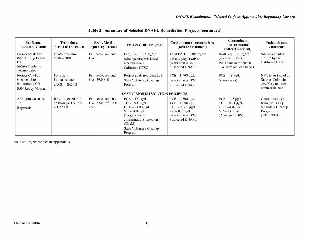
Table 2. Summary of Selected DNAPL Remediation Projects (continued)
Site Name, Location, Vendor
Technology, Period of Operation
Scale, Media, Quantity Treated
Project Goals, Program Contaminant Concentrations
(Before Treatment)
Contaminant Concentrations
(After Treatment)
Project Status, Comments
Former MGP Site (SCE), Long Beach, CA In-Situ Oxidative Technologies
In situ ozonation, 1998 – 2001
Full-scale, soil and GW
B(a)P-eq – 1.75 mg/kg (Site-specific risk-based cleanup level) California DTSC
Total PAH – 2,484 mg/kg >100 mg/kg B(a)P-eq (maximum in soil) Suspected DNAPL
B(a)P-eq – 1.4 mg/kg (average in soil) PAH concentrations in GW were reduced to ND
Site was granted closure by the California DTSC
Former Cowboy Cleaners Site, Broomfield, CO ESN Rocky Mountain
Potassium Permanganate 9/2001 – 8/2002
Full-scale, soil and GW, 29,000 ft2
Project goals not identified; State Voluntary Cleanup Program
PCE – 1,900 µg/L (maximum in GW) Suspected DNAPL
PCE – 48 µg/L (source area)
NFA letter issued by State of Colorado (2/2003), requires commercial use
IN SITU BIOREMEDIATION PROJECTS Arlington Cleaners, TX Regenesis
HRC® injected into 45 borings, 12/1999 – 11/2000
Full-scale, soil and GW, 3,500 ft2, 22 ft deep
PCE – 500 µg/L TCE – 500 µg/L DCE – 7,000 µg/L VC – 200 µg/L (Target cleanup concentrations based on CEAM) State Voluntary Cleanup Program
PCE – 4,500 µg/L TCE – 1,000 µg/L DCE – 7,300 µg/L VC – 870 µg/L (maximum in GW) Suspected DNAPL
PCE – 408 µg/L TCE – 87.4 µg/L DCE – 438 µg/L VC – 132 µg/L (Average in GW)
Conditional COC from the TCEQ Voluntary Cleanup Program (10/26/2001).
Source: Project profiles in Appendix A
December 2004 13
DNAPL Remediation: Selected Projects Approaching Regulatory Closure
Notes:
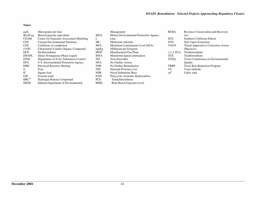
µg/L Micrograms per liter Management RCRA Resource Conservation and Recovery B(a)P-eq Benzo(a)pyrene equivalent IEPA Illinois Environmental Protection Agency Act CEAM Center for Exposure Assessment Modeling L Liter SCE Southern California Edison CES Current Environmental Solutions MC Methylene chloride SVE Soil Vapor Extraction COC Certificate of completion MCL Maximum Contaminant Level (EPA) TACO Tiered Approach to Correction Action cVOC Chlorinated Volatile Organic Compound mg/kg Milligram per kilogram Objectives DCE Dichloroethene MGP Manufactured Gas Plant 1,1,1-TCA Trichloroethane DNAPL Dense Nonaqueous-Phase Liquid MNA Monitored natural attenuation TCE Trichloroethene DTSC Department of Toxic Substances Control ND Non-detectable TCEQ Texas Commission on Environmental EPA U.S. Environmental Protection Agency NFA No Further Action Quality ERH Electrical Resistive Heating NFR No Further Remediation TRRP Texas Risk Reduction Program ft Foot NPL National Priorities List VC Vinyl chloride ft2 Square foot NSB Naval Submarine Base yd3 Cubic yard GW Ground water PAH Polycyclic Aromatic Hydrocarbon HRC® Hydrogen Release Compound PCE Tetrachloroethene IDEM Indiana Department of Environmental RBEL Risk-Based Exposure Level
December 2004 14
Appendix A
DNAPL Remediation Project Profiles
DNAPL Remediation: Selected Projects Approaching Regulatory Closure
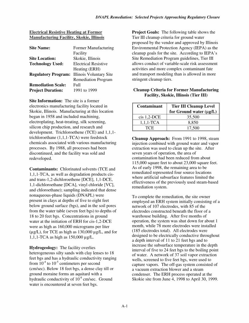
Electrical Resistive Heating at Former Manufacturing Facility, Skokie, Illinois
Site Name: Former Manufacturing Facility
Site Location: Skokie, Illinois Technology Used: Electrical Resistive
Heating (ERH) Regulatory Program: Illinois Voluntary Site
Remediation Program Remediation Scale: Full Project Duration: 1991 to 1999
Site Information: The site is a former electronics manufacturing facility located in Skokie, Illinois. Manufacturing at this location began in 1958 and included machining, electroplating, heat-treating, silk screening, silicon chip production, and research and development. Trichloroethene (TCE) and 1,1,1-trichloroethane (1,1,1-TCA) were feedstock chemicals associated with various manufacturing processes. By 1988, all processes had been discontinued, and the facility was sold and redeveloped.
Contaminants: Chlorinated solvents (TCE and 1,1,1-TCA, as well as degradation products cis-and trans-1,2-dichloroethene [DCE], 1,1-DCE, 1,1-dichloroethane [DCA], vinyl chloride [VC], and chloroethane); sampling indicated that dense nonaqueous-phase liquids (DNAPL) were present in clays at depths of five to eight feet below ground surface (bgs), and in the soil pores from the water table (seven feet bgs) to depths of 18 to 20 feet bgs. Concentrations in ground water at the initiation of ERH for cis-1,2-DCE were as high as 160,000 micrograms per liter (µg/L), for TCE as high as 130,000 µg/L, and for 1,1,1-TCA as high as 150,000 µg/L.
Hydrogeology: The facility overlies heterogeneous silty sands with clay lenses to 18 feet bgs and has a hydraulic conductivity ranging from 10-4 to 10-5 centimeters per second (cm/sec). Below 18 feet bgs, a dense clay till or ground moraine forms an aquitard with a hydraulic conductivity of 10-8 cm/sec. Ground water is encountered at seven feet bgs.
Project Goals: The following table shows the Tier III cleanup criteria for ground water proposed by the vendor and approved by Illinois Environmental Protection Agency (IEPA) as the cleanup goals for the site. According to IEPA’s Site Remediation Program guidelines, Tier III allows conduct of variable-scale risk assessment activities and more complex contaminant fate and transport modeling than is allowed in more stringent cleanup tiers.
Cleanup Criteria for Former Manufacturing Facility, Skokie, Illinois (Tier III)
Contaminant Tier III Cleanup Level for Ground water (µg/L)
cis 1,2-DCE 35,500 1,1,1-TCA 8,850
TCE 17,500
Cleanup Approach: From 1991 to 1998, steam injection combined with ground water and vapor extraction was used to clean up the site. After seven years of operation, the area of contamination had been reduced from about 115,000 square feet to about 23,000 square feet. As of early 1998, the remaining area to be remediated represented four source locations where artificial subsurface features limited the effectiveness of the previously used steam-based remediation system.
To complete the remediation, the site owner employed an ERH system initially consisting of a network of 107 electrodes, with 85 of the electrodes constructed beneath the floor of a warehouse building. After five months of operation, the system was shut down for about 1 month, while 78 more electrodes were installed (185 electrodes total). All electrodes were designed to be electrically conductive throughout a depth interval of 11 to 21 feet bgs and to increase the subsurface temperature in the depth interval of five to 24 feet bgs to the boiling point of water. A network of 37 soil vapor extraction wells, screened to five feet bgs, were used to capture vapors. The off-gas system consisted of a vacuum extraction blower and a steam condenser. The ERH process operated at the Skokie site from June 4, 1998 to April 30, 1999.
A-1
DNAPL Remediation: Selected Projects Approaching Regulatory Closure
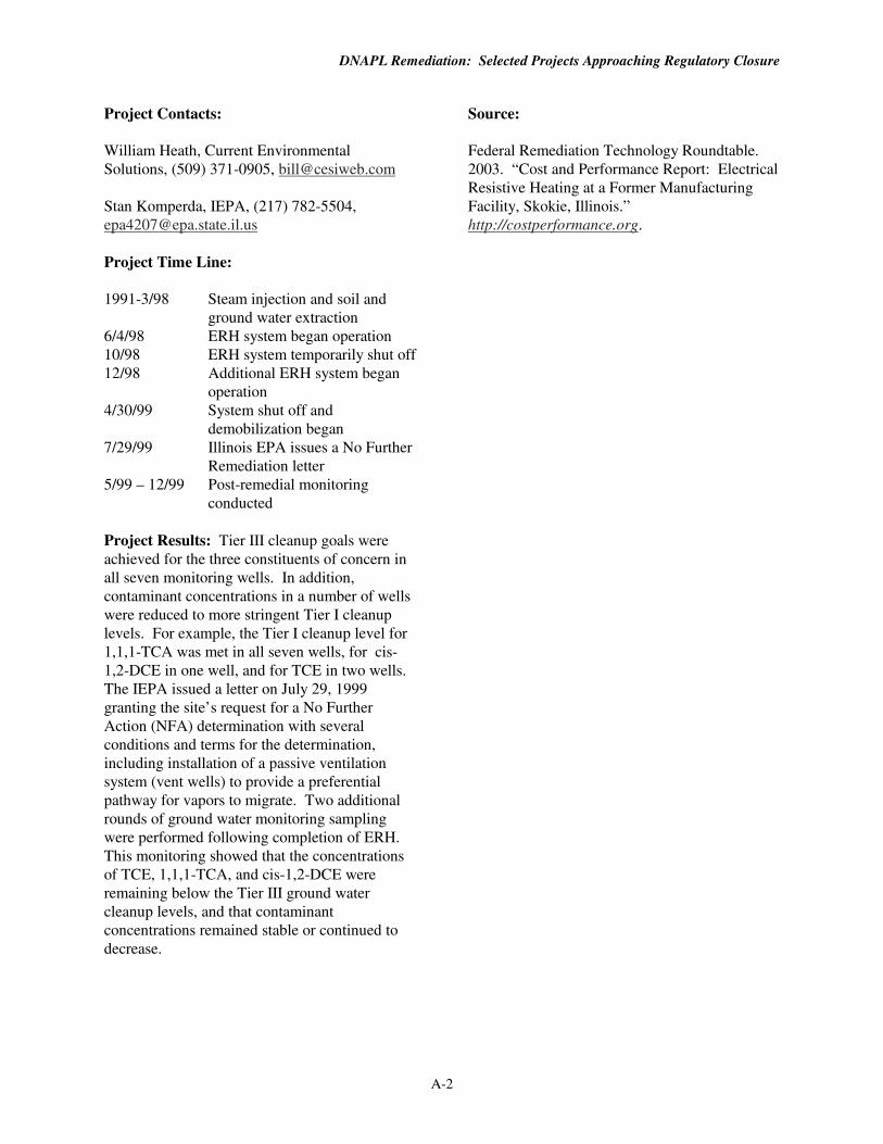
Project Contacts:
William Heath, Current Environmental Solutions, (509) 371-0905, [email protected]
Stan Komperda, IEPA, (217) 782-5504, [email protected]
Project Time Line:
1991-3/98 Steam injection and soil and ground water extraction
6/4/98 ERH system began operation 10/98 ERH system temporarily shut off 12/98 Additional ERH system began
operation 4/30/99 System shut off and
demobilization began 7/29/99 Illinois EPA issues a No Further
Remediation letter 5/99 – 12/99 Post-remedial monitoring
conducted
Project Results: Tier III cleanup goals were achieved for the three constituents of concern in all seven monitoring wells. In addition, contaminant concentrations in a number of wells were reduced to more stringent Tier I cleanup levels. For example, the Tier I cleanup level for 1,1,1-TCA was met in all seven wells, for cis-1,2-DCE in one well, and for TCE in two wells. The IEPA issued a letter on July 29, 1999 granting the site’s request for a No Further Action (NFA) determination with several conditions and terms for the determination, including installation of a passive ventilation system (vent wells) to provide a preferential pathway for vapors to migrate. Two additional rounds of ground water monitoring sampling were performed following completion of ERH. This monitoring showed that the concentrations of TCE, 1,1,1-TCA, and cis-1,2-DCE were remaining below the Tier III ground water cleanup levels, and that contaminant concentrations remained stable or continued to decrease.
Source:
Federal Remediation Technology Roundtable. 2003. “Cost and Performance Report: Electrical Resistive Heating at a Former Manufacturing Facility, Skokie, Illinois.” http://costperformance.org.
A-2
DNAPL Remediation: Selected Projects Approaching Regulatory Closure
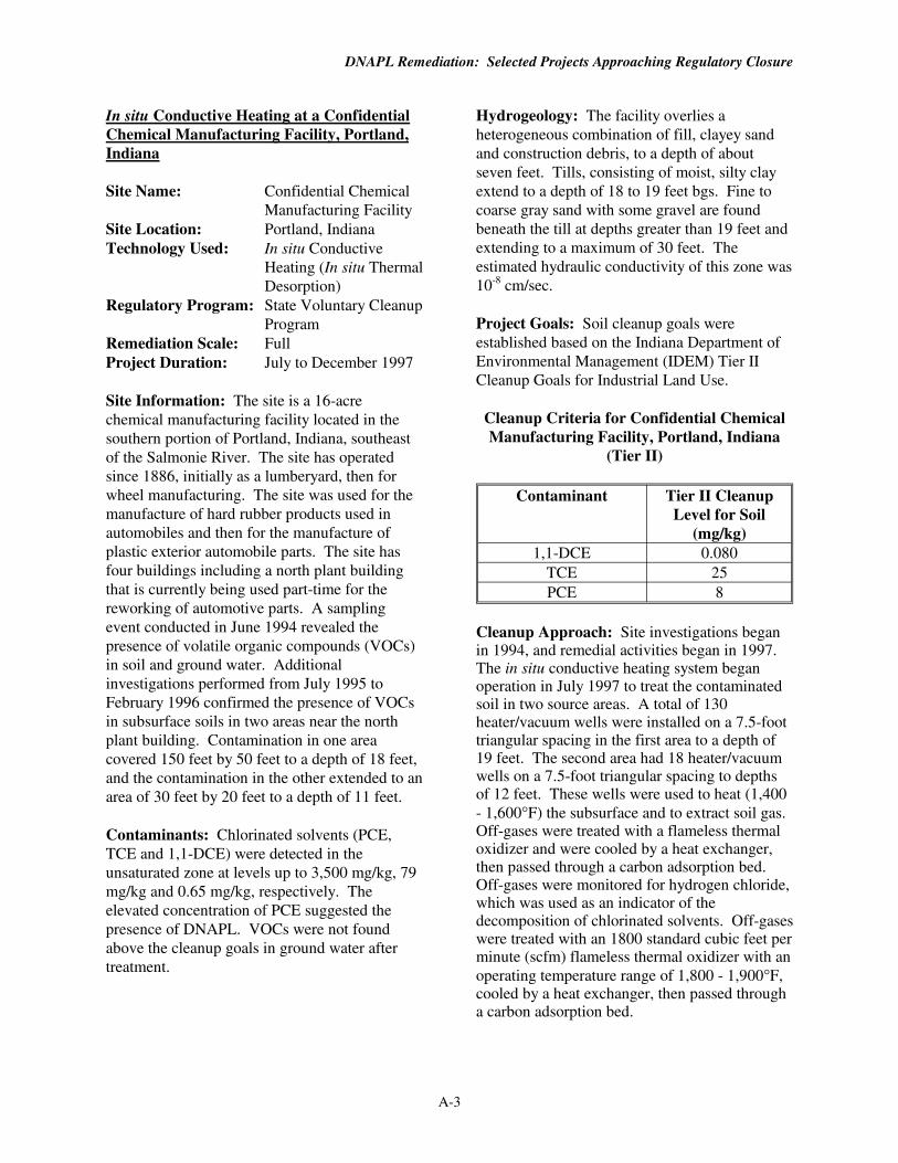
In situ Conductive Heating at a Confidential Chemical Manufacturing Facility, Portland, Indiana
Site Name: Confidential Chemical Manufacturing Facility
Site Location: Portland, Indiana Technology Used: In situ Conductive
Heating (In situ Thermal Desorption)
Regulatory Program: State Voluntary Cleanup Program
Remediation Scale: Full Project Duration: July to December 1997
Site Information: The site is a 16-acre chemical manufacturing facility located in the southern portion of Portland, Indiana, southeast of the Salmonie River. The site has operated since 1886, initially as a lumberyard, then for wheel manufacturing. The site was used for the manufacture of hard rubber products used in automobiles and then for the manufacture of plastic exterior automobile parts. The site has four buildings including a north plant building that is currently being used part-time for the reworking of automotive parts. A sampling event conducted in June 1994 revealed the presence of volatile organic compounds (VOCs) in soil and ground water. Additional investigations performed from July 1995 to February 1996 confirmed the presence of VOCs in subsurface soils in two areas near the north plant building. Contamination in one area covered 150 feet by 50 feet to a depth of 18 feet, and the contamination in the other extended to an area of 30 feet by 20 feet to a depth of 11 feet.
Contaminants: Chlorinated solvents (PCE, TCE and 1,1-DCE) were detected in the unsaturated zone at levels up to 3,500 mg/kg, 79 mg/kg and 0.65 mg/kg, respectively. The elevated concentration of PCE suggested the presence of DNAPL. VOCs were not found above the cleanup goals in ground water after treatment.
Hydrogeology: The facility overlies a heterogeneous combination of fill, clayey sand and construction debris, to a depth of about seven feet. Tills, consisting of moist, silty clay extend to a depth of 18 to 19 feet bgs. Fine to coarse gray sand with some gravel are found beneath the till at depths greater than 19 feet and extending to a maximum of 30 feet. The estimated hydraulic conductivity of this zone was 10-8 cm/sec.
Project Goals: Soil cleanup goals were established based on the Indiana Department of Environmental Management (IDEM) Tier II Cleanup Goals for Industrial Land Use.
Cleanup Criteria for Confidential Chemical Manufacturing Facility, Portland, Indiana
(Tier II)
Contaminant Tier II Cleanup Level for Soil
(mg/kg) 1,1-DCE 0.080
TCE 25 PCE 8
Cleanup Approach: Site investigations began in 1994, and remedial activities began in 1997. The in situ conductive heating system began operation in July 1997 to treat the contaminated soil in two source areas. A total of 130 heater/vacuum wells were installed on a 7.5-foot triangular spacing in the first area to a depth of 19 feet. The second area had 18 heater/vacuum wells on a 7.5-foot triangular spacing to depths of 12 feet. These wells were used to heat (1,400 - 1,600°F) the subsurface and to extract soil gas. Off-gases were treated with a flameless thermal oxidizer and were cooled by a heat exchanger, then passed through a carbon adsorption bed. Off-gases were monitored for hydrogen chloride, which was used as an indicator of the decomposition of chlorinated solvents. Off-gases were treated with an 1800 standard cubic feet per minute (scfm) flameless thermal oxidizer with an operating temperature range of 1,800 - 1,900°F, cooled by a heat exchanger, then passed through a carbon adsorption bed.
A-3
DNAPL Remediation: Selected Projects Approaching Regulatory Closure
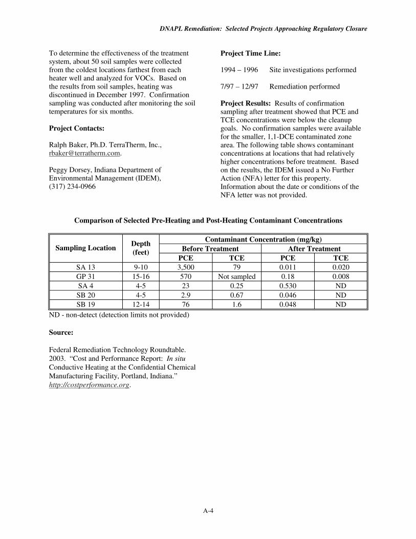
To determine the effectiveness of the treatment system, about 50 soil samples were collected from the coldest locations farthest from each heater well and analyzed for VOCs. Based on the results from soil samples, heating was discontinued in December 1997. Confirmation sampling was conducted after monitoring the soil temperatures for six months.
Project Contacts:
Ralph Baker, Ph.D. TerraTherm, Inc., [email protected].
Peggy Dorsey, Indiana Department of Environmental Management (IDEM), (317) 234-0966
Project Time Line:
1994 – 1996 Site investigations performed
7/97 – 12/97 Remediation performed
Project Results: Results of confirmation sampling after treatment showed that PCE and TCE concentrations were below the cleanup goals. No confirmation samples were available for the smaller, 1,1-DCE contaminated zone area. The following table shows contaminant concentrations at locations that had relatively higher concentrations before treatment. Based on the results, the IDEM issued a No Further Action (NFA) letter for this property. Information about the date or conditions of the NFA letter was not provided.
Comparison of Selected Pre-Heating and Post-Heating Contaminant Concentrations
Sampling Location Depth (feet)
Contaminant Concentration (mg/kg) Before Treatment After Treatment
PCE TCE PCE TCE SA 13 9-10 3,500 79 0.011 0.020 GP 31 15-16 570 Not sampled 0.18 0.008 SA 4 4-5 23 0.25 0.530 ND SB 20 4-5 2.9 0.67 0.046 ND SB 19 12-14 76 1.6 0.048 ND
ND - non-detect (detection limits not provided)
Source:
Federal Remediation Technology Roundtable. 2003. “Cost and Performance Report: In situ Conductive Heating at the Confidential Chemical Manufacturing Facility, Portland, Indiana.” http://costperformance.org.
A-4
DNAPL Remediation: Selected Projects Approaching Regulatory Closure
Electrical Resistive Heating at the Avery Dennison Site, Waukegan, Illinois
Site Name: Avery Dennison Site Site Location: Waukegan-Gurnee
Industrial Park, Illinois Technology Used: Electrical Resistive
Heating (ERH) Regulatory Program: Illinois EPA Site
Remediation Program Remediation Scale: Full Project Duration: December 1999 to
November 2000
Site Information: The site is located in the Waukegan-Gurnee Industrial Park in Waukegan, Illinois. Film coating operations were performed at this site from 1975 through 1992. Methylene chloride (MC) was used in these operations, and was transferred to above-ground storage tanks via underground piping. Site investigations showed the occurrence of MC in the soil and ground water in several areas at the site.
Contaminants: Approximately 17,000 square feet of soil along the north side of the building on the site was contaminated with MC to depths as great as 24 feet bgs, with concentrations as high as 40,000 mg/kg. MC concentrations in the soil in this area averaged 1,900 mg/kg. Information about the concentration of MC in ground water was not provided.
Hydrogeology: The underlying geology at the site is predominantly heterogeneous silty-clay, glacial till to a depth of about 180 feet bgs. Depth to ground water varies from six feet to 25 feet bgs. Bedrock is encountered at depths ranging from 180 feet to 270 feet bgs.
Project Goals: The remediation objective was to reduce the concentration of MC in the soil to below 24 mg/kg, based on IEPA’s Tiered Approach to Corrective Action Objectives (TACO).
Cleanup Approach: The treatment area was divided into 20 treatment cells. For each treatment cell, electrodes were installed around the perimeter to a depth of 24 feet. A total of 95
copper electrodes were installed including six installed below an active street, and 16 installed inside the existing building. Two thermocouples were installed in the center of each treatment cell, at the shallowest and deepest levels of contamination, four and 24 feet bgs. In addition, 34 recovery wells were installed at 20 locations to extract soil vapor and steam. The designed power input was 610 kilowatts (kW). The treatment system was expected to raise soil temperatures at a rate of at least 1oC per day until a temperature above 75oC was achieved.
Project Contacts:
Chris Thomas, Current Environmental Solutions, (847) 298-2764, [email protected]
Jennifer Seul, Illinois Environmental Protection Agency, (217)785-9399, [email protected]
Project Time Line:
1985 Removal Action 1988 Installation of grout curtain
around the former bulk storage area
1991-1994 Soil vapor extraction performed at former bulk storage area. This was ineffective and discontinued at the end of 1994.
1992-1994 Pump and treat of ground water 1994-1998 Air sparging of ground water 12/99 ERH initiated in western portion 6/00 ERH initiated in eastern portion 11/00 ERH completed 4/01 IEPA issued NFR letter
Project Results: A total of 125 soil samples were collected and analyzed for MC. Average MC concentrations in soil were reduced to 2.51 mg/kg, below the cleanup goal. Based on the results of the confirmatory samples, the IEPA issued a No Further Remediation (NFR) letter for this property in April 2001, which specified several engineering and institutional controls, including a prohibition on the installation and use of potable water supply wells in a specified area around the site.
A-5
DNAPL Remediation: Selected Projects Approaching Regulatory Closure
Source:
Federal Remediation Technology Roundtable. 2003. “Cost and Performance Report: Electrical Resistive Heating at the Avery Dennison Site, Waukegan, Illinois.” http://costperformance.org.
A-6
DNAPL Remediation: Selected Projects Approaching Regulatory Closure
In Situ Chemical Oxidation at the Kings Bay Naval Submarine Base (NSB), Site 11, Georgia
Site Name: Kings Bay NSB, Site 11 Site Location: Old Camden County,
Georgia Technology Used: In situ Chemical
Oxidation (Fenton’s Reagent)
Regulatory Program: RCRA Corrective Action
Remediation Scale: Full Project Duration: November 1998 to
January 2002
Site Information: The site is a former landfill used for disposal of municipal waste during the mid-1970s to 1980. It encompasses an area of 25 acres in Camden County in southeastern Georgia. PCE was disposed in the landfill, resulting in ground water contamination with PCE and degradation products TCE, cis-1,2-DCE, and VC. Site investigations indicated that the extent of contaminant was 120 feet long by 40 feet wide and at a depth of 30 to 40 feet bgs. The treatment area was estimated to consist of approximately 3,000 tons of contaminated soil and 80,000 gallons of contaminated ground water. Remedial activities began in the early 1990s.
Contaminants: Chlorinated solvents (PCE, TCE and cis-1,2-DCE); the maximum concentrations of contaminants were 8,500 µg/L for PCE, 550 µg/L for TCE, and 24 µg/L for cis-1,2-DCE in ground water.
Hydrogeology: The site geology is characterized as fine to medium quartz sand interbedded with silty and/or clayey sands. Ground water is encountered at six feet bgs. An unconfined surficial aquifer is approximately 90 feet thick in the vicinity of the landfill. Hydraulic conductivity is reported as 30 feet/day in the 30- to 40-foot depth interval.
Project Goals: The remediation objective was to reduce the concentration of total chlorinated aliphatic compounds (CAC) in the ground water to 100 µg/L, based on natural attenuation modeling of the downgradient plume.
Cleanup Approach: Treatment operations began in November 1998 with installation of 23 specially designed injectors in and around the area of concern. During Phase 1, a total of 8,257 gallons of Fenton’s reagent (an elemental iron/hydrogen peroxide slurry) were injected over a 19-day period, followed by Phase 2, with the injection of an additional 3,788 gallons over a 7-day period in June and July 1999. Ground water samples were collected before, during and after both phases of treatment from seven monitoring wells and two ground water recovery wells. Phase 1 treatment focused on the central part of the contaminant plume, while Phase 2 focused on the downgradient areas that were not treated in Phase 1. Following Phase 2, elevated CAC concentrations (1,700 µg/L) were detected near injector I-14, indicating the presence of a previously unidentified contamination source area. Further treatment of this area was performed during Phase 3 of remediation, which included injection of additional chemical oxidant as well as additives (including a vegetable oil) to enhance biodegradation. Specific materials and quantities injected in Phase 3 were not identified.
Project Contacts:
Clifton C. Casey, Southern Division, NAVFAC Environmental Department (843) 820-7422, [email protected]
Mary Brown, Georgia Department of Natural Resources, [email protected]
Project Time Line:
11/98-2/99 Phase 1 treatment performed 6/99-7/99 Phase 2 treatment performed 7/99-1/02 Phase 3 treatment performed
A-7
DNAPL Remediation: Selected Projects Approaching Regulatory Closure
Project Results: The contaminated area was treated in a series of injections of Fenton's reagent, followed by an injection of vegetable oil to help support biodegradation. Levels of total chlorinated hydrocarbons in the most contaminated area have been reduced from nearly 200,000 µg/L in 1999 to 120 µg/L in 2002 and currently range from <1 to 13.9 µg/L.
USGS modeling, supported by field data, indicate that at a level of approximately 100 µg/L total chlorinated hydrocarbons, monitored natural attenuation at the site will complete cleanup of the plume in approximately three years. As of May 2003, there were no longer any exceedences of MCLs in any of the off-site monitoring wells, and most of the on-site monitoring wells have had no measurable levels of contaminants. The cleanup goal of 100 µg/L has been successfully met.
Sources:
Federal Remediation Technology Roundtable. 2000. Cost and Performance Summary Report: “In Situ Chemical Oxidation Using Fenton’s Reagent at Naval Submarine Base Kings Bay, Site 11, Camden County, Georgia.”
Mary Brown, Georgia Department of Natural Resources. July 2, 2003. E-mail to Richard Weisman, Tetra Tech EM Inc. Status of Kings Bay NSB, Site 11 Cleanup.
Mary Brown, Georgia Department of Natural Resources. May 14, 2004. E-mail to Raji Ganguli, Tetra Tech EM Inc. Update on ISCO at Kings Bay NSB, Site 11, Georgia.
A-8
DNAPL Remediation: Selected Projects Approaching Regulatory Closure
In Situ Chemical Oxidation at the Parkwood Former Dry Cleaner Site, Plano, Texas
Site Name: Parkwood Former Dry Cleaner Site
Site Location: Plano, TX Technology Used: In situ Chemical
Oxidation (Fenton’s reagent)
Regulatory Program: Texas Commission on Environmental Quality (TCEQ) Voluntary Cleanup Program
Remediation Scale: Full Project Duration: December 1998 to May
2002
Site Information: The site is a former dry cleaner facility located in Plano, Texas.
Contaminants: Chlorinated solvents (PCE and TCE); Maximum initial concentrations were 2,900 µg/L for PCE, 320 µg/L for TCE, and 900 µg/L for cis-1,2-DCE in ground water. After monitoring well installation, soil samples showed maximum initial PCE concentrations of 10,000 µg/kg to 47,000 µg/kg at one to five feet bgs, and a TCE concentration of 1,500 µg/kg at six feet bgs.
Hydrogeology: The site soils consist of black or brown clay, medium to fine gravel, and traces of coarse to fine sand from the surface to 18 feet bgs. The vertical limits of the contaminant ground water plume were found at the top of the Austin Chalk bedrock, located 16 feet to 18 feet bgs.
Project Goals: The remediation objective was to reduce the concentration of chlorinated hydrocarbons in the soil to Texas Risk Reduction Program (TRRP) Tier 1 Commercial/Industrial Class 3 Ground water Risk-Based Exposure Level (RBEL) (500 µg/L for both PCE and TCE) and soil to the TRRP Tier 1 Protective Concentration levels (PCLs) (5 mg/kg PCE and 3.4 mg/kg for TCE).
Cleanup Approach: The approximate area of contamination was 0.74 acre. Remediation activities included installation of four in situ chemical oxidation injection points used to inject Fenton’s reagent as well as a proprietary surfactant. Information about the type of surfactant used or the quantities injected were not provided. For post-remediation monitoring, four soil borings were advanced and postremediation ground water sampling was conducted as well. Based on the January 2001 post-remediation sampling event, the concentration of total VOCs in ground water had been reduced by 83.2 percent to 100 percent with an average of 94 percent.
Project Contacts:
David R. Lent, CPG, IVI Environmental, Inc., (914) 694-9600
Merrie Smith, TCEQ, (512) 239-1000
Project Time Line:
1/00-11/00 Conducted in-situ chemical oxidation activities
2001 Conducted 3 rounds of postremediation ground water sampling
11/02 Certificate of completion letter issued by TCEQ
Project Results: Three post-remediation ground water-sampling events indicated that no contaminants were found above their respective standard in any of the monitoring wells. Final concentrations detected are listed as follows: 300 µg/L PCE, 52 µg/L TCE, and 91 µg/L cis-1,2-DCE. A certificate of completion letter was issued by TCEQ, stating that the property is suitable for non-residential use and does not require maintenance of engineering controls, remediation systems, post closure care, permanent institutional controls or nonpermanent institutional controls. The COC required the implementation of deed restrictions to ensure only non-residential use of the property.
A-9
DNAPL Remediation: Selected Projects Approaching Regulatory Closure
Sources:
IVI Environmental, Inc. 2002. Ground water Monitoring Report.
Texas Commission on Environmental Quality. 2002. Voluntary Cleanup Program Final Certificate of Completion.
A-10
DNAPL Remediation: Selected Projects Approaching Regulatory Closure
In Situ Chemical Oxidation at Former Southern California Edison (SCE) Manufactured Gas Plant (MGP) Site, Long Beach, California
Site Name: Former MGP Site, Long Beach, California
Site Location: Long Beach, CA Technology Used: In situ Chemical
Oxidation (Fenton’s Reagent and Ozonation)
Regulatory Program: California Department of Toxic Substances Control (DTSC)
Remediation Scale: Pilot and Full Project Duration: 1998 to 2003
Site Information: The site was used from 1902 to 1913 to produce gas from oil and coal. These processes resulted in soil and ground water contamination with PAH and total petroleum hydrocarbons (TPH).
Contaminants: Initial concentrations of contaminants were 2,484 mg/kg total PAH and 27,800 mg/kg TPH. The chemicals of potential concern identified for soil included seven carcinogenic PAHs and nine noncarcinogenic PAHs, as well as TPH. A benzo(a)pyrene equivalent (B(a)P-eq) value was calculated for each carcinogenic PAH and summed together to estimate the total B(a)P-eq concentration. Prior to treatment, B(a)P-eq in soil was slightly higher than 100 mg/kg.
Hydrogeology: The site soils consist of fill material overlying poorly sorted medium to fine grain sand. The water table is located at approximately ten feet bgs.
Project Goals: The remedial strategy was to clean up soil to meet an industrial cleanup objective of 1.75 mg/kg B(a)P-eq.
Cleanup Approach: The cleanup included a pilot study using Fenton’s chemistry and a full-scale use of in situ ozonation. A system of injection wells and direct-push points was used. Injections were made during 3-four day periods and events were conducted 3 weeks apart. An
in-situ ozonation system was operated in December 1998 to test the basic operation of the system components and to determine the subsurface flow characteristics prior to ozone injection. Ozone generation was initiated in January 1999 and continued until January 2001, when the system was shut down. During the operation of the system, 19,100 pounds of ozone and 280,000 pounds of oxygen were generated and injected.
Project Contacts:
Chris Nelson, In-Situ Oxidative Technologies, (303) 843-9079
Mike Vivas, California DTSC, (916) 255-3727
Project Time Line:
10/98-11/98 In-situ ozonation system constructed
12/98 Initial oxygen sparging conducted
1999-2003 Ozone generation conducted
Project Results: Site-wide concentrations were reduced from more than 100 mg/kg to 1.4 mg/kg of B(a)P-eq. PAH and TPH concentrations in ground water were reduced to non-detect levels after the first injection. Final post remediation contaminant concentrations in soil were not available. The site vendor reported that the site was granted closure by the California DTSC.
Sources:
In-Situ Oxidative Technologies, Inc. Case Study: Former MGP Site.
Southern California Edison. Not Dated. Remedial Action Report, Long Beach Former MGP site (excerpts).
A-11
DNAPL Remediation: Selected Projects Approaching Regulatory Closure
In Situ Chemical Oxidation at Former Cowboy Cleaners Site, Broomfield, Colorado
Site Name: Former Cowboy Cleaners Site
Site Location: Broomfield, Colorado Technology Used: In Situ Chemical
Oxidation (permanganate)
Regulatory Program: Colorado Voluntary Cleanup Program
Remediation Scale: Full Project Duration: 2001 to 2002
Site Information: The site is a former dry cleaning facility located near Denver, Colorado. A site investigation revealed the presence of soil and ground water contamination, with a ground water plume covering approximately 1.5 acres. The remediation was handled under the Colorado Voluntary Cleanup Program. The plume occupied portions of five separately owned properties and crossed a street. Small portions of the plume also flowed beneath a retail building and a residence. The State of Colorado determined that the low risks to potential receptors justified a remediation of the source area (soil), allowing the ground water to clean up naturally over time.
Contaminants: Ground water at the site is contaminated with PCE. Maximum initial concentration of PCE was 1,900 µg/L (suspected DNAPL).
Hydrogeology: Depth to ground water at the site is 25 bgs. The site consists of stiff clay to silty (sometimes sandy) clay at 3 ft bgs and a sandy clay layer at 8 ft bgs.
Project Goals: Cleanup goals not identified
Cleanup Approach: A system of 12 nested injectors was installed in the source area. Semipermanent injectors manufactured using 1” PVC screen and riser were installed to allow the controlled injection of permanganate reagent directly into the area of contamination. Each injector was installed with a sand pack to just above the screen, and grouted to the surface.
Upon setting of the grout, a charge of permanganate was pressure injected into each injector. A 10% by weight solution of permanganate was introduced into each injector, with as much volume as each injector would take, to a maximum of 100 gallons. The injectors were then connected to each other in ranks, and to a head tank by PVC piping. The gravity feeding to all of the injectors on a continuous basis was then started. Each injector was equipped with valves to control flow, and the system was kept in balance for about four to five months. Up to 300 gallons per day of 1-2% solution were fed into the system during remediation.
Most of the injectors were completely above the water table to avoid drainage of reagent directly into ground water without extensive soil contact. To control PCE that was mobilized into ground water from the soil source area, a line of injectors (curtain wall) was installed down stream. These injectors were operated at very low volumes, and controlled based on the results of a monitoring well immediately downgradient.
Project Contacts:
James H. Viellenave, ESN Rocky Mountain, (303) 278-1911, [email protected]
Mark Walker, Colorado Department of Public Health and Environment, (303) 692-3449, [email protected]
Project Time Line:
09/01 Application of permanganate 01/02 Post-treatment monitoring 08/02 Post-treatment monitoring
concluded 02/03 No Action Determination letter
issued by Colorado Department of Public Health and Environment
A-12
DNAPL Remediation: Selected Projects Approaching Regulatory Closure
Project Results: In the source area, PCE concentration started at 1,900 µg/L. One month into the remediation process, PCE concentration had dropped to 926 µg/L and continued to decrease further to 284 µg/L three months after initiation of the remedy. Post-remediation PCE concentration, monitored 8 months later, was found to be 48 µg/L. Downgradient PCE concentrations decreased from 40 µg/L to 15 µg/L within a year.
In February 2003, the State of Colorado issued a No Action Determination Approval, stating that the property could be used for commercial purposes, and did not pose an unacceptable risk to human health and the environment.
Sources:
Colorado Department of Public Health and Environment. 2003. No Action Determination Approval.
James Viellenave. December 16, 2003. E-mail to Raji Ganguli, Tetra Tech EM Inc providing information on the Former Cowboy Cleaners Site in Broomfield, Colorado.
Viellenave, J.H., J.P. Lauer, and J.V. Fontana. 2002. Using Risk Based Cleanup Goals for In Situ Chemical Oxidation of PCE in Vadose Zone Soils Under a Voluntary Cleanup Program. Paper presented at IPEC 2002. On-line address: http://ipec.utulsa.edu/Ipec/Conf2002/tech_sessio ns.html.
A-13
DNAPL Remediation: Selected Projects Approaching Regulatory Closure
In situ Bioremediation Using HRC® at a Arlington Cleaners, Arlington, Texas
Site Name: Dry Cleaning Facility Site Location: Arlington, Texas Technology Used: In situ Bioremediation
Using HRC®
Regulatory Program: Texas Commission on Environmental Quality (TCEQ) Voluntary Cleanup Program
Remediation Scale: Full Project Duration: December 1999 to
November 2000
Site Information: The site is located in Arlington, Texas, covering approximately seven acres. A former dry cleaner was situated in a small suite and operated at the site between 1982 and 1992. Environmental site assessments were conducted in 1996 and the site was admitted into the TCEQ Voluntary Cleanup Program. An unknown amount of chlorinated solvents was released at the site and had contaminated soil and ground water. The concentrations of contaminants of concern (COC) in subsurface soils at a depth of approximately eight feet below the building were in excess of site target concentrations. Site investigations revealed that the ground water with COC concentrations above the site target levels occupied approximately 3,500 square feet directly beneath and downgradient of the source area.
Contaminants: Chlorinated solvents (PCE, TCE, cis-1,2-DCE, and VC). Immediately prior to injection of HRC®, the ground water concentrations of COCs were 4,500 µg/L for PCE, 1,000 µg/L for TCE, 7,300 µg/L for cis-1,2-DCE, and 870 µg/L for VC.
Hydrogeology: The underlying rock at the site is predominantly medium to dark gray shale, which readily weathers to a thick, clayey soil. Two TCEQ-designated aquifers exist beneath the site. Site geology consists of a very low permeability light to dark brown, soft, moist clay from the ground surface to approximately 22 feet bgs. Ground water is encountered at 7 feet bgs.
Project Goals: The following table shows the target cleanup concentrations at the site, established by Conceptual Environmental Assessment Model (CEAM), a health-based risk assessment for ground water.
Cleanup Criteria for Dry Cleaning Facility, Arlington, Texas
Contaminant CEAM Cleanup Criteria for Ground water (µg/L)
PCE 500 TCE 500
cis-1,2-DCE 7,000 VC 200
Cleanup Approach: The cleanup approach included soil excavation from the source area, performed in 1998, followed by in situ bioremediation using HRC® in 2002. In May 2000, HRC® was injected into 45 borings that are located within the shallow aquifer area to a depth of approximately 22 feet bgs. Of the 45 injection borings, 29 borings were advanced perpendicular to the ground surface, and 16 borings were advanced at angles of 15 to 30 degrees from vertical to extend beneath the building’s foundation. A total of approximately 7,000 pounds of HRC® were injected at the rate of 10.37 lb/foot. Quarterly sampling of ground water was conducted as a part of the response action.
Project Contacts:
Rick Gillespie, Regenesis Inc., (972) 377-7288, [email protected].
Jacqueline Hardee, P.E., Director Remediation Division, TCEQ
Project Time Line:
1998 Soil Excavation 5/00 HRC® Injection 10/01 Conditional Certificate of
Completion issued by TCEQ
A-14
DNAPL Remediation: Selected Projects Approaching Regulatory Closure
Project Results: Approximately 18 months after HRC injection, PCE, TCE, cis-1,2-DCE, and VC in the monitoring well located nearest to the contaminant source area had decreased to 408 µg/L, 87.4 µg/L, 438 µg/L, and 132 µg/L, respectively. Based on these results, the site received a Conditional Certificate of Completion from the TCEQ Voluntary Cleanup Program on October 26, 2001.
Sources:
Koenigsberg, Stephen S. (Ed). 2002. "Case Study: Dry Cleaning Facility, Arlington, TX." In: Accelerated Bioremediation with Slow Release Electron Donors and Electron Acceptors - Selected Battelle Conference Papers 20012002.
Rick Railsback, Hardy, Shawn G., and Rick Gillespie. 2002. “Enhanced Reductive Dechlorination Results in Conditional Closure at Texas Dry Cleaner Facility.” Battelle Press.
Texas Commission on Environmental Quality (TCEQ). 2001. Voluntary Cleanup Program Conditional Certificate of Completion.
A-15
Appendix B
Suspected DNAPL Thresholds Based On Solubility Relative to One Percent of Aqueous Solubility
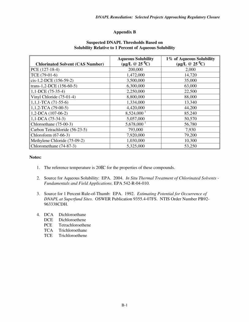
DNAPL Remediation: Selected Projects Approaching Regulatory Closure
Appendix B
Suspected DNAPL Thresholds Based on Solubility Relative to 1 Percent of Aqueous Solubility
Chlorinated Solvent (CAS Number) Aqueous Solubility
(µg/L @ 25 EC) 1% of Aqueous Solubility
(µg/L @ 25 EC) PCE (127-18-4) 200,000 2,000 TCE (79-01-6) 1,472,000 14,720 cis-1,2-DCE (156-59-2) 3,500,000 35,000 trans-1,2-DCE (156-60-5) 6,300,000 63,000 1,1-DCE (75-35-4) 2,250,000 22,500 Vinyl Chloride (75-01-4) 8,800,000 88,000 1,1,1-TCA (71-55-6) 1,334,000 13,340 1,1,2-TCA (79-00-5) 4,420,000 44,200 1,2-DCA (107-06-2) 8,524,000 1 85,240 1,1-DCA (75-34-3) 5,057,000 50,570 Chloroethane (75-00-3) 5,678,000 1 56,780 Carbon Tetrachloride (56-23-5) 793,000 7,930 Chloroform (67-66-3) 7,920,000 79,200 Methylene Chloride (75-09-2) 1,030,000 10,300 Chloromethane (74-87-3) 5,325,000 53,250
Notes:
1. The reference temperature is 20EC for the properties of these compounds.
2. Source for Aqueous Solubility: EPA. 2004. In Situ Thermal Treatment of Chlorinated Solvents - Fundamentals and Field Applications. EPA 542-R-04-010.
3. Source for 1 Percent Rule-of-Thumb: EPA. 1992. Estimating Potential for Occurrence of DNAPL at Superfund Sites. OSWER Publication 9355.4-07FS. NTIS Order Number PB92963338CDH.
4. DCA DichloroethaneDCE DichloroethenePCE TetrachloroetheneTCA Trichloroethane TCE Trichloroethene
B-1
Appendix C
Examples of Treatment Technology Providers
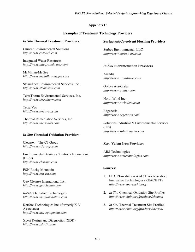
DNAPL Remediation: Selected Projects Approaching Regulatory Closure
Appendix C
Examples of Treatment Technology Providers
In Situ Thermal Treatment Providers Surfactant/Co-solvent Flushing Providers
Current Environmental Solutions Surbec Environmental, LLC http://www.cesiweb.com http://www.surbec-art.com
Integrated Water Resources http://www.integratedwater.com In Situ Bioremediation Providers
McMillan-McGee Arcadis http://www.mcmillan-mcgee.com http://www.arcadis-us.com
SteamTech Environmental Services, Inc.http://www.steamtech.com Golder Associates
http://www.golder.com
TerraTherm Environmental Services, Inc. http://www.terratherm.com North Wind Inc.
http://www.nwindenv.com Terra Vac http://www.terravac.com Regenesis
http://www.regenesis.com Thermal Remediation Services, Inc. http://www.thermalrs.com Solutions Industrial & Environmental Services
(IES) http://www.solutions-ies.com
In Situ Chemical Oxidation Providers
Cleanox – The C3 Group Zero Valent Iron Providers http://www.c3group.com
ARS Technologies Environmental Business Solutions International http://www.arstechnologies.com (EBSI) http://www.ebsi-inc.com
ESN Rocky Mountain Sources:
http://www.esn-rm.com 1. EPA REmediation And CHaracterization
Geo-Cleanse International Inc. Innovative Technologies (REACH IT)
http://www.geocleanse.com http://www.epareachit.org
In-Situ Oxidative Technologies 2. In Situ Chemical Oxidation Site Profiles http://www.insituoxidation.com http://www.cluin.org/products/chemox
Kerfoot Technologies Inc. (formerly K-V 3. In Situ Thermal Treatment Site Profiles Associates) http://www.cluin.org/products/thermal http://www.kva-equipment.com
Xpert Design and Diagnostics (XDD) http://www.xdd-llc.com
C-1


![Enhanced Remediation of DNAPL- Contaminated Subsurface … · Reference: Hill et. al. [ES&T, 35(14), 2001] 35. 36 Three-Dimensional Liquid Saturated Downward Vertical Displacement](https://img.pdfslide.net/doc/110x75/5f798ee42fe82c2ede526f5d/enhanced-remediation-of-dnapl-contaminated-subsurface-reference-hill-et-al-est.jpg)


![Project on Brine-Based Remediation of DNAPL-Contaminated ...•Reference: Hill et. al. [ES&T, 35(14), 2001] Three-Dimensional Unsaturated Downward Vertical Displacement of TCE](https://img.pdfslide.net/doc/110x75/5f7993fff33015046c46664e/project-on-brine-based-remediation-of-dnapl-contaminated-areference-hill.jpg)