Embed Size (px)
Citation preview
ICP/EXT-04-00210Revision 2
Project No. 24059
Health and Safety Plan for the OU 7-13/14 Early Actions Beryllium Encapsulation Project
June 2004
Idaho Completion Project Idaho Falls, Idaho 83415
Prepared for the U.S. Department of Energy
Assistant Secretary for Environmental Management Under DOE Idaho Operations Office
Contract DE-AC07-99ID13727
iii
ABSTRACT
This health and safety plan establishes the requirements and controls that will eliminate or minimize health and safety hazards associated with personnel conducting in situ grouting of beryllium block activities at locations inside the Subsurface Disposal Area of the Radioactive Waste Management Complex.
This health and safety plan has been prepared to meet the requirements of the Occupational Safety and Health Administration standard, “Hazardous Waste Operations and Emergency Response.” This health and safety plan contains information about the hazards involved in performing in situ grouting tasks and about specific actions and equipment that will be used to protect persons while working at the task site.
The intent of this document is to identify known hazards and to provide a plan for mitigating them. The safety and health professionals supporting these tasks, in conjunction with the subcontractor and subcontractor technical representative conducting these activities, must determine the most appropriate hazard control and mitigation measures based on site-specific conditions and should make changes to this document as appropriate.

iv
v
CONTENTS
ABSTRACT.................................................................................................................................................iii
ACRONYMS............................................................................................................................................... xi
1. INTRODUCTION...........................................................................................................................1-1
1.1 Purpose ...............................................................................................................................1-1
1.2 Idaho National Engineering and Environmental Laboratory Site Description..................1-2
1.2.1 Radioactive Waste Management Complex .........................................................1-2 1.2.2 Beryllium Blocks Buried at the Radioactive Waste Management Complex ......1-5
1.3 Scope ..................................................................................................................................1-5
1.3.1 Grouting Process .................................................................................................1-5
1.4 Additional Activities ..........................................................................................................1-7
2. KEY SITE PERSONNEL RESPONSIBILITIES ...........................................................................2-1
2.1 Task-Site Responsibilities ..................................................................................................2-1
2.1.1 Beryllium Block In Situ Grouting Project Manager ...........................................2-1 2.1.2 Radioactive Waste Management Complex Environment, Safety, and
Health Manager...................................................................................................2-1 2.1.3 Radioactive Waste Management Complex Balance of Plant Nuclear
Facility Manager .................................................................................................2-3 2.1.4 Beryllium Block In Situ Grouting Project Engineer ...........................................2-3 2.1.5 Construction Management Superintendent .........................................................2-3 2.1.6 Construction Management Construction Coordinator ........................................2-3 2.1.7 Construction Management Subcontract Technical Representative.....................2-4 2.1.8 Bechtel BWXT Idaho, LLC, Safety Engineer.....................................................2-4 2.1.9 Bechtel BWXT Idaho, LLC, Industrial Hygienist ..............................................2-4 2.1.10 Bechtel BWXT Idaho, LLC, Radiological Control Engineers............................2-5 2.1.11 Bechtel BWXT Idaho, LLC, Radiological Control Technicians ........................2-5 2.1.12 Bechtel BWXT Idaho, LLC, Environmental Professionals ................................2-5 2.1.13 Bechtel BWXT Idaho, LLC, Quality Assurance Engineer .................................2-5 2.1.14 Bechtel BWXT Idaho, LLC, Field Technical Support........................................2-5 2.1.15 Subcontractor Superintendent .............................................................................2-5 2.1.16 Subcontractor Health and Safety Officer/Safety Representative ........................2-6 2.1.17 Subcontractor Field Team...................................................................................2-6 2.1.18 Nonfield Team Workers......................................................................................2-6 2.1.19 Visitors ................................................................................................................2-7
3. RECORDKEEPING REQUIREMENTS........................................................................................3-1
3.1 Industrial Hygiene and Radiological Monitoring Records.................................................3-1
vi
3.2 Site Attendance Record ......................................................................................................3-1
4. PERSONNEL TRAINING..............................................................................................................4-1
4.1 General Training.................................................................................................................4-2
4.2 Project-Specific Health and Safety Plan Training..............................................................4-2
4.3 Daily Plan-of-the-Day Briefing and Lessons Learned .......................................................4-3
5. OCCUPATIONAL MEDICAL SURVEILLANCE PROGRAM ...................................................5-1
5.1 Bechtel BWXT Idaho, LLC, Employee Medical Surveillance Requirements ...................5-1
5.2 Subcontractor Employee Medical Surveillance Requirements ..........................................5-2
5.3 Biological Monitoring Programs........................................................................................5-2
5.3.1 Industrial Hygiene Biological Monitoring Programs..........................................5-2 5.3.2 Radiological Assay Program...............................................................................5-2
5.4 Injuries on the Site..............................................................................................................5-2
6. ACCIDENT PREVENTION PROGRAM ......................................................................................6-1
6.1 Voluntary Protection Program and Integrated Safety Management...................................6-1
6.2 General Safe-Work Practices .............................................................................................6-2
6.3 As Low as Reasonably Achievable Principles ...................................................................6-4
6.3.1 External Radiation Dose Reduction ....................................................................6-4 6.3.2 Internal Radiation Dose Reduction .....................................................................6-4 6.3.3 Chemical Contaminant Exposure Avoidance .....................................................6-4
6.4 The Buddy System .............................................................................................................6-5
7. SITE CONTROL AND SECURITY...............................................................................................7-1
7.1 Exclusion Zone...................................................................................................................7-1
7.2 Contamination Reduction Zone..........................................................................................7-1
7.3 Construction Area...............................................................................................................7-2
7.4 Radiological Control Area..................................................................................................7-3
7.5 Site Security .......................................................................................................................7-3
7.6 Wash Facilities and Designated Eating Areas....................................................................7-3
7.7 Designated Smoking Area..................................................................................................7-3
vii
8. HAZARD ASSESSMENT..............................................................................................................8-1
8.1 Beryllium Block In Situ Grouting Contaminants of Concern ............................................8-1
8.1.1 Nonradioactive Contaminants of Concern ..........................................................8-1 8.1.2 Radioactive Contaminants of Concern................................................................8-9
8.2 Routes of Exposure...........................................................................................................8-10
8.3 Environmental and Personnel Monitoring........................................................................8-10
8.3.1 Industrial Hygiene Monitoring..........................................................................8-11 8.3.2 Industrial Hygiene Instrument and Equipment Calibration ..............................8-11 8.3.3 Beryllium Exposure Levels...............................................................................8-11
8.4 Physical and Environmental Hazard Evaluation, Control, and Monitoring .....................8-11
8.4.1 Physical Hazards ...............................................................................................8-11 8.4.2 Environmental Hazards.....................................................................................8-14
8.5 Other Site Hazards and Inspections..................................................................................8-17
9. PERSONAL PROTECTIVE EQUIPMENT ...................................................................................9-1
9.1 Project-Specific Personal Protective Equipment Requirements.........................................9-1
9.2 Personal Protective Equipment Levels ...............................................................................9-2
9.3 Protective Clothing Upgrading and Downgrading .............................................................9-2
9.4 Inspection of Personal Protective Equipment.....................................................................9-2
10. DECONTAMINATION PROCEDURES.....................................................................................10-1
10.1 Contamination Control and Prevention ............................................................................10-1
10.2 Equipment and Personnel Decontamination.....................................................................10-1
10.2.1 Equipment Decontamination.............................................................................10-1 10.2.2 Personnel Decontamination ..............................................................................10-2
11. EMERGENCY RESPONSE PLAN..............................................................................................11-1
11.1 Types of Emergency Events .............................................................................................11-2
11.1.1 Events Requiring Emergency Notifications......................................................11-2 11.1.2 Events Requiring Local Project Evacuation or Idaho National Engineering
and Environmental Laboratory Emergency Response Organization Response ...........................................................................................................11-2
11.1.3 Events Requiring Total Facility and Project Evacuation ..................................11-3
11.2 Emergency Facilities and Equipment ...............................................................................11-3
viii
11.3 Emergency Communications............................................................................................11-4
11.4 Emergency Recognition and Prevention ..........................................................................11-4
11.5 Emergency Response Roles and Responsibilities ............................................................11-4
11.5.1 The Idaho National Engineering and Environmental Laboratory and Radioactive Waste Management Complex Emergency Response Organization......................................................................................................11-4
11.5.2 Project Personnel Involved in Emergencies......................................................11-5 11.5.3 Spills .................................................................................................................11-5 11.5.4 Alarms...............................................................................................................11-6 11.5.5 Personnel Accountability and Area Warden .....................................................11-7 11.5.6 Notifications......................................................................................................11-7 11.5.7 Evacuation Assembly Areas and Central Facilities Area Medical Facility ......11-8
11.6 Reentry and Recovery ......................................................................................................11-8
11.6.1 Reentry..............................................................................................................11-8 11.6.2 Recovery ...........................................................................................................11-8
11.7 Critique of Response and Follow-up..............................................................................11-10
11.8 Telephone and Radio Contact Reference List ................................................................11-11
12. REFERENCES..............................................................................................................................12-1
FIGURES
1-1. Location of the Radioactive Waste Management Complex at the Idaho National Engineering and Environmental Laboratory.......................................................................................................1-3
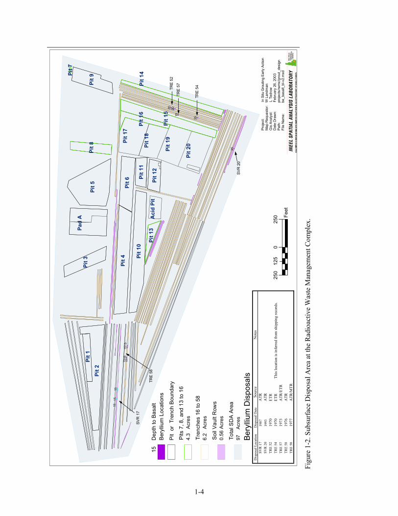
1-2. Subsurface Disposal Area at the Radioactive Waste Management Complex ................................1-4
1-3. Conceptual schematic of in situ grouting .......................................................................................1-6
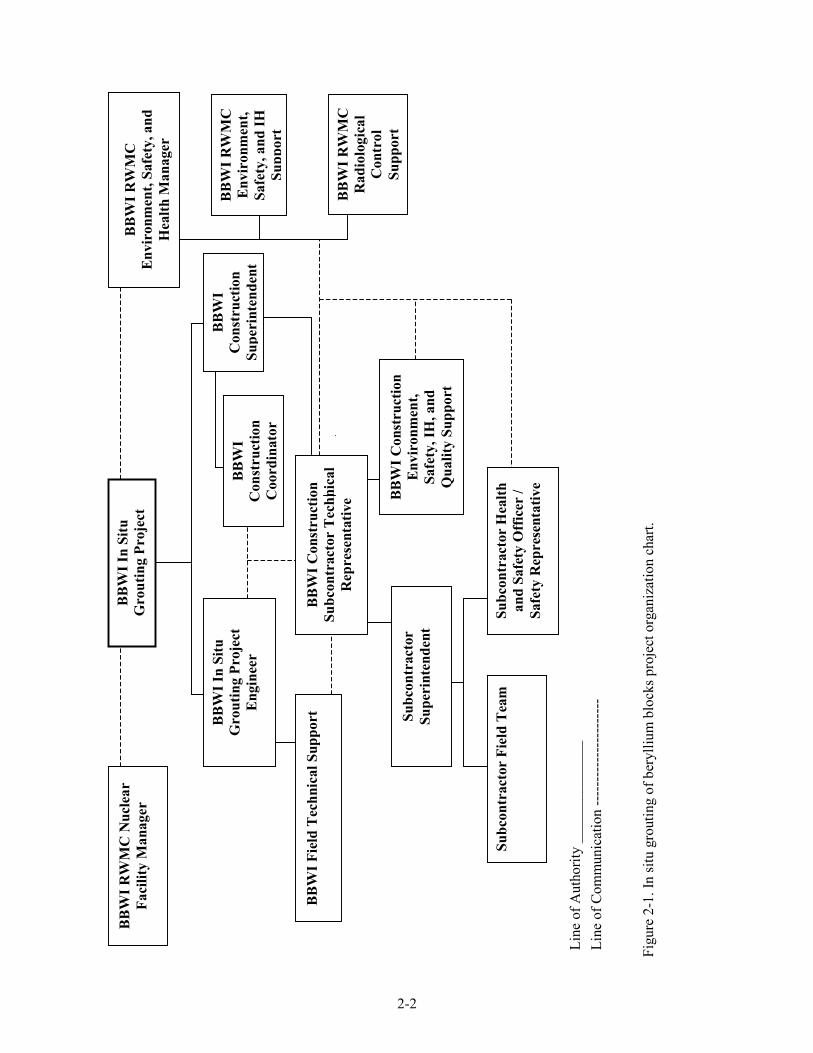
2-1. In situ grouting of beryllium blocks project organization chart .....................................................2-2
7-1. Example configuration of a work control area ...............................................................................7-2
11-1. Radioactive Waste Management Complex primary and secondary evacuation assembly areas ..............................................................................................................................11-9
11-2. Map showing the route to the nearest medical facility (CFA-1612) ..........................................11-10
ix
TABLES
4-1. Required project training table. ......................................................................................................4-1
8-1. Grouting waste location, description, and activity .........................................................................8-2
8-2. Evaluation of chemical and radiological hazards at grouting locations .........................................8-4
8-3. Grouting tasks, associated hazards, and mitigation........................................................................8-7
8-4. Grouting project hazards monitoring..............................................................................................8-8
8-5. Equipment available for monitoring grouting project hazards .......................................................8-9
8-6. Heat stress signs and symptoms ...................................................................................................8-15
11-1. Emergency response equipment to be maintained at the site during operations ..........................11-3
11-2. Responsibilities during an emergency..........................................................................................11-5
11-3. Project internal emergency signals ...............................................................................................11-6

x
xi
ACRONYMS
ACGIH American Conference of Government Industrial Hygienists
ATR Advanced Test Reactor
BBWI Bechtel BWXT Idaho, LLC
COC contaminant of concern
DOE U.S. Department of Energy
ERO emergency response organization
ES&H environment, safety, and health
ETR Engineering Test Reactor
FTL field team leader
HASP health and safety plan
HAZWOPER hazardous waste operations and emergency response
HSO health and safety officer
IARC International Agency for Research on Cancer
IH industrial hygienist
INEEL Idaho National Engineering and Environmental Laboratory
ISMS Integrated Safety Management System
JSA job safety analysis
MSDS material safety data sheet
MTR Materials Test Reactor
NIOSH National Institute of Occupational Safety and Health
NTP National Toxicology Program
OMP Occupational Medical Program
OSHA Occupational Safety and Health Administration
POC point of contact
POD plan of the day
xii
PPE personal protective equipment
PWO project work order
RadCon Radiological Control
RCT radiological control technician
RWMC Radioactive Waste Management Complex
RWP radiological work permit
SDA Subsurface Disposal Area
SRM Subcontractor Requirements Manual
STEL short-term exposure limit
STR subcontractor technical representative
SWP safe-work permit
TLV threshold limit value
TRU transuranic
VOC volatile organic compound
VPP Voluntary Protection Program
WCC Warning Communications Center
1-1
Health and Safety Plan for the OU 7-13/14 Early Actions Beryllium Encapsulation Project
1. INTRODUCTION
1.1 Purpose
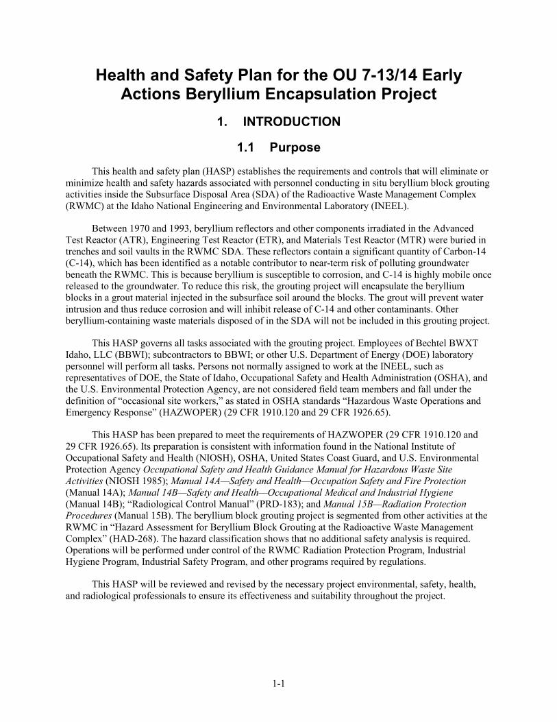
This health and safety plan (HASP) establishes the requirements and controls that will eliminate or minimize health and safety hazards associated with personnel conducting in situ beryllium block grouting activities inside the Subsurface Disposal Area (SDA) of the Radioactive Waste Management Complex (RWMC) at the Idaho National Engineering and Environmental Laboratory (INEEL).
Between 1970 and 1993, beryllium reflectors and other components irradiated in the Advanced Test Reactor (ATR), Engineering Test Reactor (ETR), and Materials Test Reactor (MTR) were buried in trenches and soil vaults in the RWMC SDA. These reflectors contain a significant quantity of Carbon-14 (C-14), which has been identified as a notable contributor to near-term risk of polluting groundwater beneath the RWMC. This is because beryllium is susceptible to corrosion, and C-14 is highly mobile once released to the groundwater. To reduce this risk, the grouting project will encapsulate the beryllium blocks in a grout material injected in the subsurface soil around the blocks. The grout will prevent water intrusion and thus reduce corrosion and will inhibit release of C-14 and other contaminants. Other beryllium-containing waste materials disposed of in the SDA will not be included in this grouting project.
This HASP governs all tasks associated with the grouting project. Employees of Bechtel BWXT Idaho, LLC (BBWI); subcontractors to BBWI; or other U.S. Department of Energy (DOE) laboratory personnel will perform all tasks. Persons not normally assigned to work at the INEEL, such as representatives of DOE, the State of Idaho, Occupational Safety and Health Administration (OSHA), and the U.S. Environmental Protection Agency, are not considered field team members and fall under the definition of “occasional site workers,” as stated in OSHA standards “Hazardous Waste Operations and Emergency Response” (HAZWOPER) (29 CFR 1910.120 and 29 CFR 1926.65).
This HASP has been prepared to meet the requirements of HAZWOPER (29 CFR 1910.120 and 29 CFR 1926.65). Its preparation is consistent with information found in the National Institute of Occupational Safety and Health (NIOSH), OSHA, United States Coast Guard, and U.S. Environmental Protection Agency Occupational Safety and Health Guidance Manual for Hazardous Waste Site Activities (NIOSH 1985); Manual 14A—Safety and Health—Occupation Safety and Fire Protection (Manual 14A); Manual 14B—Safety and Health—Occupational Medical and Industrial Hygiene (Manual 14B); “Radiological Control Manual” (PRD-183); and Manual 15B—Radiation Protection Procedures (Manual 15B). The beryllium block grouting project is segmented from other activities at the RWMC in “Hazard Assessment for Beryllium Block Grouting at the Radioactive Waste Management Complex” (HAD-268). The hazard classification shows that no additional safety analysis is required. Operations will be performed under control of the RWMC Radiation Protection Program, Industrial Hygiene Program, Industrial Safety Program, and other programs required by regulations.
This HASP will be reviewed and revised by the necessary project environmental, safety, health, and radiological professionals to ensure its effectiveness and suitability throughout the project.
1-2
1.2 Idaho National Engineering and Environmental Laboratory Site Description
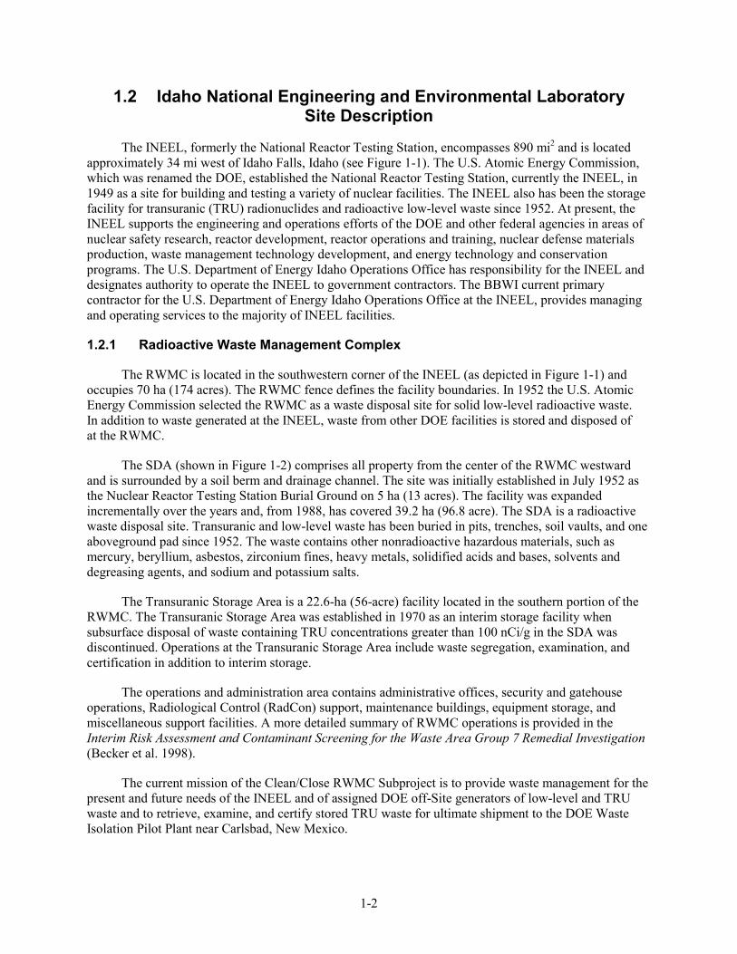
The INEEL, formerly the National Reactor Testing Station, encompasses 890 mi2 and is located approximately 34 mi west of Idaho Falls, Idaho (see Figure 1-1). The U.S. Atomic Energy Commission, which was renamed the DOE, established the National Reactor Testing Station, currently the INEEL, in 1949 as a site for building and testing a variety of nuclear facilities. The INEEL also has been the storage facility for transuranic (TRU) radionuclides and radioactive low-level waste since 1952. At present, the INEEL supports the engineering and operations efforts of the DOE and other federal agencies in areas of nuclear safety research, reactor development, reactor operations and training, nuclear defense materials production, waste management technology development, and energy technology and conservation programs. The U.S. Department of Energy Idaho Operations Office has responsibility for the INEEL and designates authority to operate the INEEL to government contractors. The BBWI current primary contractor for the U.S. Department of Energy Idaho Operations Office at the INEEL, provides managing and operating services to the majority of INEEL facilities.
1.2.1 Radioactive Waste Management Complex
The RWMC is located in the southwestern corner of the INEEL (as depicted in Figure 1-1) and occupies 70 ha (174 acres). The RWMC fence defines the facility boundaries. In 1952 the U.S. Atomic Energy Commission selected the RWMC as a waste disposal site for solid low-level radioactive waste. In addition to waste generated at the INEEL, waste from other DOE facilities is stored and disposed of at the RWMC.
The SDA (shown in Figure 1-2) comprises all property from the center of the RWMC westward and is surrounded by a soil berm and drainage channel. The site was initially established in July 1952 as the Nuclear Reactor Testing Station Burial Ground on 5 ha (13 acres). The facility was expanded incrementally over the years and, from 1988, has covered 39.2 ha (96.8 acre). The SDA is a radioactive waste disposal site. Transuranic and low-level waste has been buried in pits, trenches, soil vaults, and one aboveground pad since 1952. The waste contains other nonradioactive hazardous materials, such as mercury, beryllium, asbestos, zirconium fines, heavy metals, solidified acids and bases, solvents and degreasing agents, and sodium and potassium salts.
The Transuranic Storage Area is a 22.6-ha (56-acre) facility located in the southern portion of the RWMC. The Transuranic Storage Area was established in 1970 as an interim storage facility when subsurface disposal of waste containing TRU concentrations greater than 100 nCi/g in the SDA was discontinued. Operations at the Transuranic Storage Area include waste segregation, examination, and certification in addition to interim storage.
The operations and administration area contains administrative offices, security and gatehouse operations, Radiological Control (RadCon) support, maintenance buildings, equipment storage, and miscellaneous support facilities. A more detailed summary of RWMC operations is provided in the Interim Risk Assessment and Contaminant Screening for the Waste Area Group 7 Remedial Investigation (Becker et al. 1998).
The current mission of the Clean/Close RWMC Subproject is to provide waste management for the present and future needs of the INEEL and of assigned DOE off-Site generators of low-level and TRU waste and to retrieve, examine, and certify stored TRU waste for ultimate shipment to the DOE Waste Isolation Pilot Plant near Carlsbad, New Mexico.

1-3
Figure 1-1. Location of the Radioactive Waste Management Complex at the Idaho National Engineering and Environmental Laboratory.
1-4
Pit 5
Pit 4
Pit 2
Pit 1
0
Pit 1
5
Pit 6
Pit 9
Pit 3
Pit 8
Pit 1
Pit 1
2
Pit 1
1Pi
t 16
Pit 1
3
Pit 7
1515
1515
25
20 2015
25
1515
15
Proj
ect:
In
Situ
Gro
utin
g Ea
rly A
ctio
nM
ap R
eque
stor
: W
Lan
dman
Gis
Ana
lyst
:
L
Ted
row
Dat
e D
raw
n:
Febr
uary
26,
200
3Pa
th:
proj
ects
/rwm
c/gr
out_
desi
gnFi
le N
ame:
b
e_ba
salt_
bl-v
2.m
xd
Bery
llium
Loc
atio
ns
Pit
or T
renc
h Bo
unda
ry
Pits
7, 8
, and
13
to 1
64.
3 A
cres
Tren
ches
16
to 5
86.
2 A
cres
Soi
l Vau
lt R
ows
0.56
Acr
es
Tota
l SD
A A
rea
97
Acr
es
250
025
012
5
Feet
Pad
A Aci
d Pi
t
Bery
llium
Dis
posa
lsSV
R 2
0
TRE
54
TRE
52
TRE
58
SVR
17
Pit 1
4
Pit 1
7
Pit 1
8
Pit 1
9
Pit 2
0
15
Dep
th to
Bas
alt
TRE
57
Dis
posa
l Loc
atio
n D
ispo
sal D
ate
Sour
ceN
otes
SVR
1719
87A
TRSV
R 20
1993
ATR
TRE
5219
70ET
RTR
E 54
1970
ETR
This
loca
tion
is in
ferr
ed fr
om sh
ippi
ng re
cord
s.TR
E 57
1973
ATR
/ETR
TRE
5819
76A
TRTR
E 58
1977
ATR
/MTR
Fi
gure
1-2
. Sub
surf
ace
Dis
posa
l Are
a at
the
Rad
ioac
tive
Was
te M
anag
emen
t Com
plex
.
1-5
1.2.2 Beryllium Blocks Buried at the Radioactive Waste Management Complex
Between 1970 and 1993, beryllium reflectors and other components irradiated in the ATR, ETR, and MTR were buried in trenches and soil vaults in the RWMC SDA. The disposed-of beryllium was used as a neutron reflector in INEEL test nuclear reactors. It includes 20 beryllium blocks from ATR Cores 1, 2, and 3; nine outer shim control cylinders from ATR Cores 1 and 2; and one beryllium reflector assembly each from the MTR and ETR. The beryllium reflector waste was disposed of in 1970, 1976, 1977, 1987, and 1993. The total disposed-of beryllium is 4,742 kg (10,454 lb).
Each ATR beryllium reflector block is 51 in. long and can be fit in a circle nominally 20 in. in diameter with a metal volume of 1.55 ft3 and a mass of 179.5 lb. The outer shim control cylinders are circular cylinders that hold hafnium plates used to control the reactor flux. They are 7.25 in. in diameter and 46.8 in. long and weigh 125 lb. The MTR reflector comprised a large number of variously shaped pieces, each 38.98 in. high. The total mass was 5,750 lb. The ETR had four reflector blocks of 4.5 × 35 × 37.5 in. that weighed 310 lb. The mass of ETR disposed-of beryllium is estimated to be 1,278.6 lb.
The beryllium blocks were disposed of in steel packages as remote-handled low-level waste having exposure rates higher than 500 mR/hour at 3.28 ft. In some cases, the containers were fully or partially covered with Herculite.
1.3 Scope
The scope of the in situ grouting of the beryllium blocks includes site preparation activities, including installation of grout containment units; mobilization of equipment to the SDA locations; placement of the grout; stabilization of the grouted locations; demobilization of equipment; and all support activities associated with conducting the grouting activities in the SDA.
The beryllium block grouting project will be performed in specified trenches and soil vaults in the SDA of the RWMC as indicated in Figure 1-2. The beryllium blocks buried in the trenches are collocated with other waste. For segmentation, collocated waste buried within 10 ft of the beryllium blocks will be considered part of this activity. There is no driving mechanism to cause the collocated waste beyond 10 ft to be affected by or involved in activities related to grouting. The beryllium blocks buried in the soil vaults are in holes physically separated from other waste by the surrounding soil.
The desired result on in situ grouting of beryllium blocks in SDA trenches and soil vault rows is the formation of a stabilized waste monolith with low hydraulic conductivity. The result will be to minimize the infiltration of water, which will reduce corrosion of the blocks and the migration of contaminants of concern (COCs) from the blocks.
1.3.1 Grouting Process
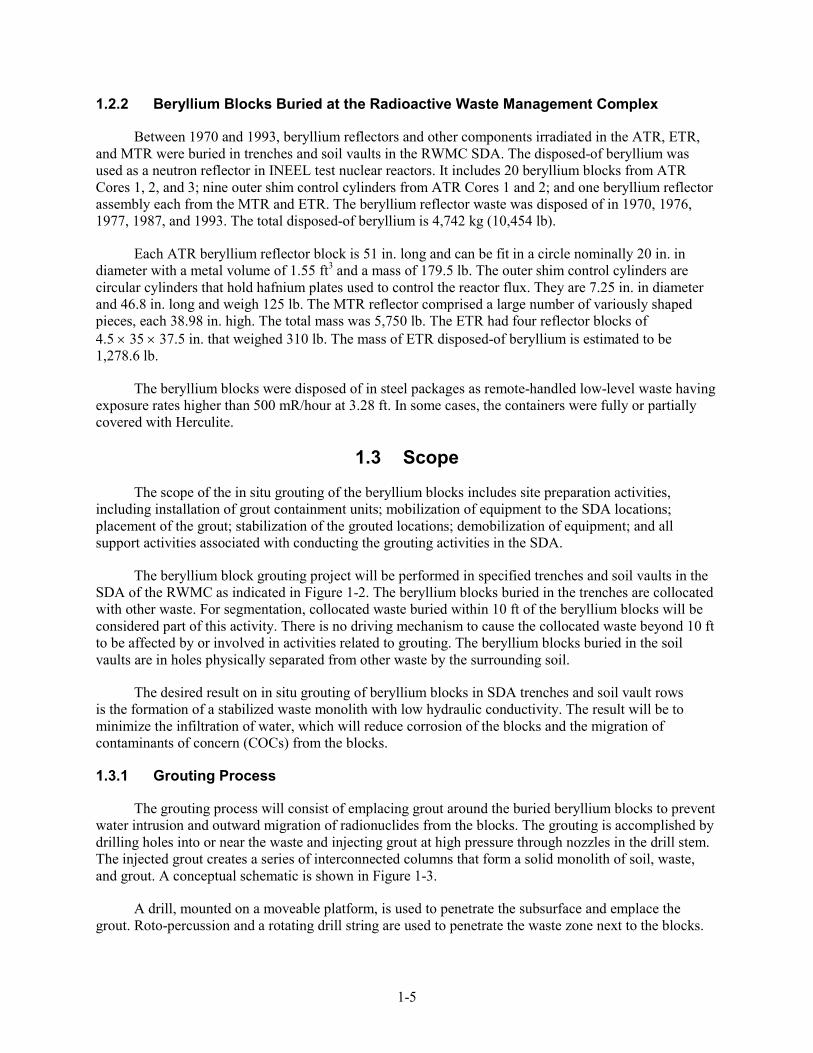
The grouting process will consist of emplacing grout around the buried beryllium blocks to prevent water intrusion and outward migration of radionuclides from the blocks. The grouting is accomplished by drilling holes into or near the waste and injecting grout at high pressure through nozzles in the drill stem. The injected grout creates a series of interconnected columns that form a solid monolith of soil, waste, and grout. A conceptual schematic is shown in Figure 1-3.
A drill, mounted on a moveable platform, is used to penetrate the subsurface and emplace the grout. Roto-percussion and a rotating drill string are used to penetrate the waste zone next to the blocks.
1-6
Figure 1-3. Conceptual schematic of in situ grouting.
The drill pipe is hollow, and grout is fed at high pressure to nozzles at the end of the drill stem. Penetration of the beryllium blocks is not intended. Once the drill stem is inserted into the basalt interface below the waste seam, grout is injected using the nozzles typically located 180 degrees apart on the bottom of the drill stem. The drill string is then withdrawn in discrete, predetermined steps. The time spent on any given step and the rotation of the drill vary depending on waste, grout, and soil type. Grouting is stopped at the top of the waste material, leaving at least a 3-ft barrier of ungrouted overburden material.
1-7
As the grout is injected near the top of the column, some grout material will extrude out of the ground and create a pool of grout, called grout returns, on the surface. The percentage of grout returns varies with the viscosity of the grout, the permeability of the soil and waste, and the depth where grouting is terminated. This grout may entrain subsurface contaminants and transport them to the surface. These contaminants will be mixed with the grout and not readily released. As the grout hardens, it will contain these contaminants. The grout containment will minimize the potential for contamination spread by containing the contaminated grout returns. The grout containment units may be ventilated during grouting to further enhance worker protection. A layer of clean grout may be placed over the grout returns to prevent releasing entrained contaminants. Also, additional clean soil cover will be added for contouring and closure.
1.4 Additional Activities
Ancillary activities that may be performed in conjunction with in situ grouting activities include the following:
• Install grout containment units
• Prepare or revise existing National Environmental Policy Act documentation, including an environmental checklist (as required)
• Prepare work control documentation and integrated planning sheets in accordance with “Integrated Work Control Process” (STD-101)
• Complete a hazards screening checklist and job walk-downs
• Prepare a job safety analysis (JSA)
• Submit document action requests for changes or revisions to the existing project plan or other project documents.

1-8
2-1
2. KEY SITE PERSONNEL RESPONSIBILITIES
The organizational structure for this project reflects the resources and expertise required to perform the work while minimizing risks to worker health and safety, the environment, and the general public. The primary Early Actions Beryllium Project positions, lines of responsibility and communication, and the project structure are shown on the organization chart for the project (see Figure 2-1). This organization chart is not all-inclusive but shows the structure for resources assigned to complete field tasks. The following subsections outline the responsibilities of key site personnel.
2.1 Task-Site Responsibilities
2.1.1 Beryllium Block In Situ Grouting Project Manager
The project manager has the ultimate responsibility for the technical quality of the project, for maintaining a safe environment, and for the safety and health of all personnel during field activities performed by or for the project. The project manager provides technical coordination and interfaces with the U.S. Department of Energy Idaho Operations Office. The project manager ensures that:
• Project and program activities are conducted in accordance with all applicable federal, state, local, and company requirements and agreements
• Project budgets and schedules are approved and monitored to be within budgetary guidelines
• Personnel, equipment, subcontractors, and services are available
• Direction is provided for the development of tasks, evaluation of findings, development of conclusions and recommendations, and production of reports.
2.1.2 Radioactive Waste Management Complex Environment, Safety, and Health Manager
The RWMC environment, safety, and health (ES&H) manager, or designee, is responsible to manage ES&H resources to ensure that ES&H programs, policies, standards, procedures, and mandatory requirements are planned, scheduled, implemented, and executed in day-to-day operations for the RWMC. The manager directs the ES&H compliance accomplishments of all activities by providing technical and administrative direction to subordinate staff, and by coordinating with related functional entities. The ES&H manager represents the project in all ES&H matters. This includes responsibility for project ES&H management compliance and oversight for all Comprehensive Environmental Response, Compensation and Liability Act (42 USC § 9601 et seq., 1980) operations planned and conducted at the RWMC.
2-2
Figu
re 2
-1. I
n si
tu g
rout
ing
of b
eryl
lium
blo
cks p
roje
ct o
rgan
izat
ion
char
t.
Line
of A
utho
rity
____
____
____
__
Line
of C
omm
unic
atio
n ---
----
----
----
----
---
Subc
ontr
acto
r Su
peri
nten
dent
BB
WI C
onst
ruct
ion
Env
iron
men
t, Sa
fety
, IH
, and
Q
ualit
y Su
ppor
t
BB
WI R
WM
C N
ucle
ar
Faci
lity
Man
ager
BB
WI F
ield
Tec
hnic
al S
uppo
rt
BB
WI R
WM
C
Env
iron
men
t, Sa
fety
, and
H
ealth
Man
ager
BB
WI R
WM
C
Env
iron
men
t, Sa
fety
, and
IH
Supp
ort
BB
WI C
onst
ruct
ion
Subc
ontr
acto
r T
echn
ical
R
epre
sent
ativ
e B
BW
I RW
MC
R
adio
logi
cal
Con
trol
Su
ppor
t
Subc
ontr
acto
r H
ealth
an
d Sa
fety
Off
icer
/ Sa
fety
Rep
rese
ntat
ive
Subc
ontr
acto
r Fi
eld
Tea
m
BB
WI I
n Si
tu
Gro
utin
g Pr
ojec
t
BB
WI
Con
stru
ctio
n Su
peri
nten
dent
BB
WI
Con
stru
ctio
n C
oord
inat
or
BB
WI I
n Si
tu
Gro
utin
g Pr
ojec
t E
ngin
eer
2-3
2.1.3 Radioactive Waste Management Complex Balance of Plant Nuclear Facility Manager
The RWMC balance of plant nuclear facility manager ensures all activities conducted during the project comply with the RWMC safety authorization, as applicable. The nuclear facility manager shall review the project and provide oversight to ensure the work is executed safely and the project activities are integrated with other RWMC facilities and projects.
2.1.4 Beryllium Block In Situ Grouting Project Engineer
The project engineer is responsible for the overall technical quality of the project as well as for the technical content and quality of project deliverables. Additional responsibilities of the project engineer include:
• Providing project-specific point-of-contact (POC) services for the recruitment and staffing of projects for the scientific, technical, and engineering staff
• Being cognizant and staying ahead of technical project issues and focusing on planning, design, and execution of tasks to ensure compliance with environmental regulations, permits, INEEL policies, and DOE orders
• Maintaining close coordination with other key project POCs to maintain project schedules and milestones and to develop action plans (as required) that meet project goals
• Coordinating and scheduling formal and informal reviews of all project-produced documentation to ensure scientific, technical, and engineering excellence in the delivered product
• Coordinating and planning appropriate mitigation strategies to minimize long-term impacts of the tasks conducted
• Being responsible for technical oversight and direction in development and acceptance of products and deliverables
• Identifying scientific, technical, and engineering issues that affect the cost-effectiveness, constructability, and operation or maintenance of systems developed for deployment.
2.1.5 Construction Management Superintendent
The construction management superintendent at the RWMC is responsible for providing recommendations and information during project planning and design concerning constructability issues and overall construction management strategies. The construction management superintendent will be responsible for overseeing the subcontract requirements in accordance with the project plan, schedule, and budget. The construction management superintendent is responsible for ensuring that adequate construction management support staffing is provided to support the subcontract as necessary to execute the project tasks.
2.1.6 Construction Management Construction Coordinator
The construction management construction coordinator is responsible for implementing the construction phase of the project in the field. The construction coordinator will monitor progress on work packages for cost, schedule, and technical performance of the project. The construction coordinator will
2-4
resolve claims and change orders with appropriate input from the construction management superintendent, project engineer, and project manager. The construction coordinator will coordinate dispute resolution between the subcontractor and BBWI and will ensure that requirements of the subcontract are enforced.
2.1.7 Construction Management Subcontract Technical Representative
The construction management subcontract technical representative (STR) interacts with the subcontractor to coordinate and ensure that field activities are conducted in compliance with the requirements of the subcontract and that all tasks at the job site are conducted in a safe and compliant manner. All health and safety issues must be brought to the attention of the STR. Specific responsibilities include:
• Enforcing task-site control and documenting field activities
• Ensuring project-specific briefings and reviews are completed in accordance with the requirements outlined in “Performing Pre-Job Briefings and Documenting Feedback” (MCP-3003)
• Reviewing and approving contractor invoices
• Enforcing terms and conditions of the contract
• Enforcing and coordinating ES&H requirements and activities and overseeing compliance with BBWI Subcontractor Requirements Manual (SRM) (TOC-59)
• Managing emergency and accident response and coordination
• Conducting ES&H and quality assurance inspections
• Coordinating and administering contract warranty issues
• Performing contract close-out activities.
2.1.8 Bechtel BWXT Idaho, LLC, Safety Engineer
Safety engineering support from BBWI will be provided by construction management safety engineers and RWMC safety engineers. Safety support will be coordinated through the STR to provide oversight of the subcontractor’s implementation of applicable safety and health requirements and mitigations included in this HASP, the JSA, project work order (PWO), SRM (TOC-59), and safe-work permit (SWP). Noncritical issues will be coordinated through the STR for resolution with the subcontractor. The safety engineers may interact directly with the subcontractor’s health and safety officer (HSO) to identify and recommend resolutions to hazards requiring immediate action. The safety engineers will be responsible for ensuring this HASP remains current with the work and shall update it as necessary.
2.1.9 Bechtel BWXT Idaho, LLC, Industrial Hygienist
The IH support from BBWI will be provided by construction management industrial hygienists (IHs) and RWMC IHs. Support will be coordinated through the STR to provide oversight of the subcontractor’s implementation of applicable safety and health requirements and mitigations included in this HASP, the JSA, PWO, SRM, and SWP. Noncritical issues will be coordinated through the STR for
2-5
resolution with the subcontractor. The IH may interact directly with the subcontractor’s HSO to identify and recommend resolutions to hazards requiring immediate action.
The IH support personnel will provide sampling and monitoring support for all BBWI personnel and will provide the subcontractor with IH sampling and monitoring support related to volatile organic compounds (VOCs) and beryllium exposure. The IH will work through the STR to recommend changes to personal-protective-equipment levels based on the actual field conditions.
2.1.10 Bechtel BWXT Idaho, LLC, Radiological Control Engineers
The radiological engineer provides radiological support to the project. Specific duties and responsibilities include acting as the POC for all radiation protection issues related to the project and ensuring that radiological hazards are identified and that appropriate controls are implemented to maintain worker exposure to radiological hazards as low as reasonably achievable.
2.1.11 Bechtel BWXT Idaho, LLC, Radiological Control Technicians
The radiological control technicians (RCTs) provide field monitoring and sampling support to the project. The RCTs will monitor implementation of RadCon requirements during all field activities and shall ensure that all field activities are conducted in accordance with the radiological work permit (RWP) and the applicable radiological control procedures in the SRM.
2.1.12 Bechtel BWXT Idaho, LLC, Environmental Professionals
The environmental professionals provide overall technical expertise related to environmental regulatory issues, natural and cultural resources, waste minimization, waste disposition, and environmental oversight to the project.
2.1.13 Bechtel BWXT Idaho, LLC, Quality Assurance Engineer
The quality assurance engineer provides or coordinates the project monitoring, assessments, and surveillance to ensure that the materials and supplies used on the project meet the applicable requirements for quality assurance.
2.1.14 Bechtel BWXT Idaho, LLC, Field Technical Support
Field technical support personnel provide the project with recommendations for successful technical completion of the project and perform oversight to ensure that the work is completed in accordance with the project objectives. The technical support personnel will interface with the subcontractor through the STR and will report to the project engineer. The technical support personnel are responsible to understand and comply with the applicable safety and health requirements and hazard mitigations in the HASP, SRM, JSA, PWO, SWP, and RWP.
2.1.15 Subcontractor Superintendent
The subcontractor superintendent represents the subcontractor at the work site and implements the subcontract requirements. The subcontractor superintendent is a full-time position required on the project. The subcontractor superintendent will work subcontract and safety issues through the STR and will be the POC for all issues related to the subcontract work while working onsite.
2-6
2.1.16 Subcontractor Health and Safety Officer/Safety Representative
The subcontractor HSO is a full-time position and requires the HSO to be onsite at all times during subcontract field operations. This may be the same person and may fulfill the same duties as the subcontractor safety representative. The HSO must have the knowledge necessary to implement the HASP and verify compliance with applicable safety and health requirements. The HSO is responsible for ensuring the safety, health, and radiological requirements are implemented for the subcontractor and for enforcing the requirements for all personnel at the worksite. The following are the subcontractor safety-representative-specific responsibilities:
• Ensures that all subcontractors and personnel comply with the applicable requirements of the HASP, SRM, JSA, SWP, and RWP
• Enforces the project safety standards and requirements in cooperation with the BBWI STR, BBWI safety engineer, BBWI IH, and BBWI RCTs
• Conducts project inspections of equipment, structures, and work in progress to ensure safety and health requirements are implemented
• Plans and coordinates weekly safety meetings to all construction personnel
• Maintains records of all safety-related incidences, including injury and illness investigations
• Submits for approval and maintains the Superfund Amendments and Reauthorization Act Title III reports, Hazardous Materials List, and material safety data sheets (MSDSs).
2.1.17 Subcontractor Field Team
The subcontractor field team includes all personnel working for the subcontractor, or subcontractors to the subcontractor. The subcontractor field team personnel are responsible to understand and execute work in compliance with the applicable safety and health requirements and hazard mitigations in the HASP, SRM, JSA, PWO, SWP, and RWP.
2.1.18 Nonfield Team Workers
All persons who may be at the work site during operations and are not part of the field team (e.g., surveyor or others not assigned in an operational support role) are considered nonfield team members as defined by this HASP. A person will be considered onsite when they are present in the work-area boundary (described in detail in Section 7).
Nonfield team members are considered occasional Site workers in accordance with the HAZWOPER (29 CFR 1910.120) and must receive site-specific HASP training before entering the work-area boundary of the project site. They must also meet all required training for the area of the site they have a need to access. Also, an OSHA-qualified site supervisor will supervise nonfield team personnel who have not completed their 3 days of supervised field experience in accordance with the HAZWOPER.
2-7
2.1.19 Visitors
All visitors with official business at the project site (including INEEL personnel, representatives of DOE, and state or federal regulatory agencies) may only proceed into the work-area boundary during operational activities after meeting the following requirements:
• Receive site-specific HASP training or hazard briefing based on specific tasks taking place
• Provide proof of meeting all training requirements specified in Section 4
• Review and sign applicable JSA rosters for the particular operation or area(s) to be accessed
• Provide objective evidence of PPE training and wearing the appropriate PPE for the area of the site accessed (29 CFR 1910.132).
A fully trained task-site representative (e.g., STR, HSO, or a designated alternate) will escort visitors when entering the work-control boundary at the project site, as site conditions warrant, and as deemed appropriate by the STR.
NOTE: Visitors will not be allowed into controlled work areas during certain tasks to minimize risks to visitors. The determination of a visitor’s need for access into the work-area boundary will be made by the STR and subcontractor superintendent, in consultation with the HSO and safety professional as appropriate.
A casual visitor to the task site is a person who does not have a specific task to perform or other official business to conduct at the project site. Casual visitors are not permitted on the project site.

2-8
3-1
3. RECORDKEEPING REQUIREMENTS
3.1 Industrial Hygiene and Radiological Monitoring Records
When BBWI IH support is required, the IH will record airborne monitoring and sampling data (both area and personal) collected for exposure assessments in the INEEL hazards assessment and sampling system. All monitoring and sampling equipment will be maintained and calibrated according to INEEL procedures and the manufacturer specifications. Industrial hygiene airborne monitoring and sampling exposure assessment data are treated as limited access information and maintained by the IH in accordance with Manual 14B—Safety and Health—Occupational Medical and Industrial Hygiene (Manual 14B) procedures.
The RCT maintains a logbook of radiological monitoring, daily project operational activities, and instrument calibrations. Radiological monitoring records are maintained in accordance with Manual 15B—Radiation Protection Procedures (Manual 15B).
Project personnel or their representatives have a right to the monitoring and sampling data (both area and personal) of both the IH and the RCT. Results from monitoring data may be communicated to all field personnel during daily plan-of-the-day (POD) meetings and formal prejob briefings in accordance with “Performing Pre-Job Briefings and Documenting Feedback” (MCP-3003).
Subcontractor monitoring and sampling information will be provided by the subcontractor to the STR for inclusion in the project file.
3.2 Site Attendance Record
A site attendance record will be used to keep a record of all personnel (i.e., field team members and nonfield team members) onsite each day and to assist the area warden with conducting personnel accountability, should an evacuation take place (see Section 11 for emergency evacuation conditions). Personnel only will be required to sign in and out of the attendance record once each day. The STR is responsible for maintaining the site attendance record and for ensuring that all personnel on the project site sign in.

3-2
4-1
4. PERSONNEL TRAINING
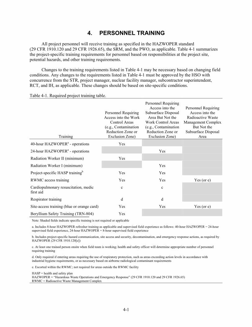
All project personnel will receive training as specified in the HAZWOPER standard (29 CFR 1910.120 and 29 CFR 1926.65), the SRM, and the PWO, as applicable. Table 4-1 summarizes the project-specific training requirements for personnel based on responsibilities at the project site, potential hazards, and other training requirements.
Changes to the training requirements listed in Table 4-1 may be necessary based on changing field conditions. Any changes to the requirements listed in Table 4-1 must be approved by the HSO with concurrence from the STR, project manager, nuclear facility manager, subcontractor superintendent, RCT, and IH, as applicable. These changes should be based on site-specific conditions.
Table 4-1. Required project training table.
Training
Personnel Requiring Access into the Work
Control Areas (e.g., Contamination Reduction Zone or Exclusion Zone)
Personnel Requiring Access into the
Subsurface Disposal Area But Not the
Work Control Areas (e.g., Contamination Reduction Zone or Exclusion Zone)
Personnel Requiring Access into the
Radioactive Waste Management Complex
But Not the Subsurface Disposal
Area
40-hour HAZWOPERa - operations Yes
24-hour HAZWOPERa - operations Yes
Radiation Worker II (minimum) Yes
Radiation Worker I (minimum) Yes
Project-specific HASP trainingb Yes Yes
RWMC access training Yes Yes Yes (or e)
Cardiopulmonary resuscitation, medic first aid
c c
Respirator training d d
Site-access training (blue or orange card) Yes Yes Yes (or e)
Beryllium Safety Training (TRN-804) Yes Note: Shaded fields indicate specific training is not required or applicable
a. Includes 8-hour HAZWOPER refresher training as applicable and supervised field experience as follows: 40-hour HAZWOPER = 24-hour supervised field experience, 24-hour HAZWOPER = 8-hour supervised field experience
b. Includes project-specific hazard communication, site access and security, decontamination, and emergency response actions, as required by HAZWOPER (29 CFR 1910.120[e])
c. At least one trained person onsite when field team is working; health and safety officer will determine appropriate number of personnel requiring training
d. Only required if entering areas requiring the use of respiratory protection, such as areas exceeding action levels in accordance with industrial hygiene requirements, or as necessary based on airborne radiological contaminant requirements
e. Escorted within the RWMC; not required for areas outside the RWMC facility
HASP = health and safety plan HAZWOPER = “Hazardous Waste Operations and Emergency Response” (29 CFR 1910.120 and 29 CFR 1926.65) RWMC = Radioactive Waste Management Complex
4-2
4.1 General Training
All project personnel are responsible for meeting required training (including applicable refresher training). Evidence of training will be maintained by the subcontractor at the project site or must be available electronically (e.g., Training Records and Information Network). Nonfield team personnel and visitors must be able to provide evidence of meeting required training for the area of the site they wish to access before being allowed into project areas.
Examples of acceptable written training documents include: (1) a 40-hour OSHA HAZWOPER card, (2) a respirator authorization card, (3) a medic or first-aid training card, or (4) a copy of an individual's or department’s (INEEL only) Training Records and Information Network system printout demonstrating completion of training. Upon validation, a copy of the training certificate issued by an approved non-INEEL training vender or institution is also acceptable proof of training. As a minimum, all personnel who access the controlled work location are required to wear PPE and must provide objective evidence of having completed INEEL computer-based PPE training (00TRN288), or equivalent, in accordance with “Personal Protective Equipment” (29 CFR 1910, Subpart I).
4.2 Project-Specific Health and Safety Plan Training
Before beginning work at the project site, project-specific HASP training will be conducted by the HSO (or designee). This training will consist of a complete review of a current copy of the project HASP with time for discussion and questions. Project-specific HASP training can be conducted in conjunction with or separately from the required formal prejob briefing (MCP-3003).
The project-specific HASP training will be documented by electronically acknowledging completion of reading the HASP in EDMS; by signing on Form 361.25, “Group Read and Sign Training Roster,” for the HASP; or by an equivalent means approved by the STR that indicates the individual has reviewed the HASP, understands the project tasks and associated hazards and mitigations, and agrees to follow all HASP and applicable work safety requirements.
A trained OSHA HAZWOPER 8-hour supervisor (HSO or other person trained as a HAZWOPER supervisor) will monitor each newly 24-hour or 40-hour trained worker’s performance to meet the 1 or 3 days of supervised field experience, respectively, in accordance with HAZWOPER (29 CFR 1910.120[e]). Following the supervised field experience period, the supervisor will complete Form 361.47, “Hazwoper Supervised Field Experience Verification,” or equivalent, to document the supervised field experience.
NOTE: Supervised field experience is only required if personnel have not previously completed this on-the-job training at another Comprehensive Environmental Response, Compensation, and Liability Act site (documented), or they are upgrading from 24- to 40-hour HAZWOPER training. A copy must be kept at the project site as evidence of training or be available electronically.

4-3
4.3 Daily Plan-of-the-Day Briefing and Lessons Learned
The subcontractor superintendent or designee will conduct a daily POD meeting. During this meeting, daily tasks are to be outlined; hazards identified; hazard controls, mitigation, and work zones reviewed; PPE requirements discussed; and employee questions answered. At the completion of this meeting, any new work control documents will be read and signed (e.g., SWPs and JSAs).
Particular emphasis will be placed on lessons learned from the previous day’s activities and how tasks can be completed in the safest, most efficient manner. All personnel will be asked to contribute ideas to enhance worker safety and mitigate potential exposures at the project sites.

4-4
5-1
5. OCCUPATIONAL MEDICAL SURVEILLANCE PROGRAM
Task-site personnel will participate in either the INEEL Occupational Medical Program (OMP), as required by “Hazardous Waste Operations and Emergency Response” (MCP-2748) for BBWI employees, or HAZWOPER-compliant medical surveillance program for subcontractor personnel. Medical surveillance examinations will be provided without cost to the employee before assignment, annually, after termination of HAZWOPER duties or employment, as soon as possible upon notification by an employee that the employee has developed signs or symptoms indicating possible overexposure to hazardous substances, or when an employee has been injured or exposed above published exposure levels in an emergency situation. This includes the following personnel:
• Personnel who are or may be exposed to hazardous substances at or above the OSHA permissible exposure limit or published exposure limits without regard to respirator use for 30 or more days per year
• All personnel who wear a respirator for 30 days or more a year or as required by “Respiratory Protection” (29 CFR 1910.134)
• All employees who are injured, become ill, or develop signs or symptoms because of possible overexposure involving hazardous substances or health hazards from an emergency response or hazardous waste operation.
Personnel who wear a respirator in performance of their job, or who are required to take respirator training to perform their duties under this plan, must participate, at least annually, in the medical evaluation program for respirator use, as required by “Respiratory Protection” (29 CFR 1910.134).
A copy of the project HASP, the JSA, exposure assessments, PPE requirements, MSDSs, and other exposure-related information will be made available upon request to the OMP physician (and subcontractor physicians) conducting medical surveillance for employees participating in this project. Exposure monitoring results and hazard information furnished to the physician must be supplemented or updated annually as long as the employee is required to maintain a hazardous waste or material employee medical clearance.
Initial exposure evaluation indicates that personnel exposure to hazardous substances at or above the action levels for substance-specific materials is not anticipated. If regulatory mandated substance-specific standard action levels are triggered, then affected personnel will be enrolled in the applicable substance-specific medical monitoring program in accordance with “Occupational Safety and Health Standards” and “Safety and Health Regulations for Construction” (29 CFR 1910; 29 CFR 1926).
5.1 Bechtel BWXT Idaho, LLC, Employee Medical Surveillance Requirements
The OMP physician will evaluate the physical ability of each BBWI employee to perform the work assigned, as identified in the site HASP or other job-related documentation. A documented medical clearance (e.g., physician’s written opinion) will be provided to the employee and line management stating whether the employee has any detected medical condition that would place him or her at increased risk of material health impairment from work in hazardous waste operations, emergency response operations, respirator-use areas, or confined-space entry areas (as applicable). The physician may impose restrictions on the employee by limiting the amount and type of work performed.
5-2
5.2 Subcontractor Employee Medical Surveillance Requirements
As required, subcontractor project personnel will participate in a subcontractor medical surveillance program that satisfies the requirements of HAZWOPER (29 CFR 1910.120; 29 CFR 1926.65). This program must make medical examinations available before assignment, annually, and after termination of hazardous waste duties. The physician’s written opinion will serve as documentation that subcontractor personnel are fit for duty.
Medical data from the subcontractor employee’s private physician, collected pursuant to hazardous material worker qualification, will be made available to the INEEL OMP physicians upon request.
5.3 Biological Monitoring Programs
5.3.1 Industrial Hygiene Biological Monitoring Programs
The IH, in conjunction with the subcontractor HSO, shall review exposure potential to nonradiological COCs and establish biological monitoring requirements as required in applicable substance-specific standards. The BBWI and subcontractor employees will participate as required, if identified as applicable.
5.3.2 Radiological Assay Program
All subcontractor and BBWI employees working inside the posted radiological areas at the work site will participate in a radiological assay program. Personnel will be required to have a baseline radiological assay before beginning work onsite. The program is a random selection and event-based program. Each month during onsite work activities, a random process based on a preset percentage will identify personnel to participate in the radiological assay program. Also, any personnel involved in an incident involving an unanticipated release of radiological contamination will be required to participate in the radiological assay process.
5.4 Injuries on the Site
It is policy of the INEEL that an OMP physician will examine all injured personnel if (1) an employee is injured on the job, (2) an employee is experiencing signs and symptoms consistent with exposure to a hazardous material, or (3) there is reason to believe that an employee has been exposed to toxic substances or physical or radiological agents in excess of allowable limits.
NOTE: In the event of an injury, subcontractor employees will be taken to the closest INEEL medical facility (CFA-1612) to have an injury stabilized before transport to the subcontractor’s treating physician or medical facility.
In the event of a known or suspected injury or illness because of exposure to a hazardous substance or physical or radiological agent, the employee will be transported to the nearest INEEL medical facility for evaluation and treatment, as necessary. The HSO is responsible for obtaining as much of the following information as is available to accompany the individual to the medical facility:
• Name, job title, work (site) location, and supervisor’s name and phone number
• Substance, physical or radiological agent exposed to (known or suspected), and MSDS, if available
5-3
• Nature of the incident, injury, or exposure and related signs or symptoms of exposure
• First aid or other measures taken
• Locations, dates, and results of any airborne exposure monitoring or sampling
• PPE in use during this work (e.g., type of respirator and cartridge used).
Further medical evaluation will be determined by the treating or examining physician, according to the signs and symptoms observed, hazard involved, exposure level, and specific medical surveillance requirements established by the OMP director in compliance with HAZWOPER (29 CFR 1910.120).
The RWMC shift supervisor will be contacted if any injury or illness occurs at the project site. As soon as possible after an injured employee has been transported to the INEEL medical facility, the STR or designee will make notifications as indicated in Section 11.

5-4
6-1
6. ACCIDENT PREVENTION PROGRAM
It is important that all project personnel understand and follow the project-specific requirements and hazard mitigations of the HASP, JSA, SWP, SRM, RWP, and PWO. Engineering controls, hazard isolation, work practices and training, and the use of PPE will all be implemented to eliminate or mitigate potential hazards and personnel exposures. However, all project personnel have responsibilities in the hazard identification and control process. These include:
• Participation in the hazards identification process based on the scope of work.
• Participation in the hazard walk-downs of the areas where routine monitoring activities will take place.
• Assistance in the completion of hazard-screening checklists or hazard-profile-screening checklists (as applicable).
• Attendance at the prejob briefing and subsequent PODs to ensure all workers have a clear understanding of the scope of work, associated hazards, and mitigation requirements. The daily POD and postjob briefing provide a formal forum for sharing lessons learned and contributing ideas for safer and more efficient ways to do work.
NOTE: If the scope of work, hazards identified, hazard mitigation (including PPE requirements), or work control documentation is not clearly understood, personnel will ask the subcontractor superintendent or STR for clarification before signing the prejob attendance sheet and before starting work.
• Recognition of changing field conditions, scope of work, and new hazards requiring mitigation and taking appropriate action to communicate these conditions to the subcontractor superintendent, STR, or HSO and stop work (where appropriate) in accordance with “Stop Work Authority” (PRD-1004) until new scope or hazards are adequately addressed in work control documents and mitigation is in place.
6.1 Voluntary Protection Program and Integrated Safety Management
The INEEL safety processes embrace the Voluntary Protection Program (VPP) and Integrated Safety Management System (ISMS) criteria, principles, and concepts as part of operational excellence. All levels of management are responsible for implementing safety policies and programs and for maintaining a safe and healthy work environment. Project personnel and subcontractors are expected to take a proactive role in preventing accidents, ensuring safe working conditions for themselves and fellow personnel, and complying with all work control documents and procedures.
The ISMS is focused on the system side of conducting operations, and VPP concentrates on the people side of conducting work, but both define work scope and identify, analyze, and mitigate hazards. The VPP is a process that promotes and encourages continuous safety improvement; however, it is not a requirement of any regulatory agency. The INEEL and affected subcontractors participate in VPP and integrated safety management for the safety of their employees. Additional information regarding the
6-2
INEEL VPP and ISMS programs can be found in “INEEL Line Management and Operations Manual” (PDD-1005). The five key elements of VPP and ISMS are:
Voluntary Protection Program Integrated Safety Management System
Management leadership Define work scope
Employee involvement Analyze hazards
Worksite analysis Develop and implement controls
Hazard prevention and control Perform work within controls
Safety and health training Provide feedback and improvement
6.2 General Safe-Work Practices
The following practices are mandatory for all INEEL and subcontractor personnel working on the project sites. All visitors entering the controlled work areas must follow these practices. The STR, subcontractor superintendent, and HSO are responsible for ensuring the following hazard control practices are followed at the project site:
NOTE: Failure to follow these practices may result in permanent removal from the site and other disciplinary actions.
• Access into the controlled work area will be limited to authorized INEEL, subcontractor, and visitor personnel only.
• DO NOT enter the controlled work area or areas posted with DANGER signs unless authorized by the STR or subcontractor superintendent.
• Comply with all safety signs, color codes, and barriers, and DO NOT cross safety or radiological barriers unless you understand the hazard within and have the proper training to access the area.
NOTE: Potable water may be consumed in designated locations of the SDA for heat stress relief after implementation of supplemental measures and with concurrence from BBWI RadCon and Industrial Hygiene.
• No eating, drinking, chewing gum or tobacco, smoking, applying cosmetics or skin creams, or participating in any other practice that increases the probability of ingestion or absorption of materials will be allowed, except in designated eating or break areas.
• Wear all required PPE (minimum of Level D).
• Be aware of walking and working surface conditions (i.e., uneven, soft, hot, wet, snow, mud, frost, ice-covered), and wear adequate footwear to prevent slips and falls.
• Do not wear finger rings, loose clothing, wristwatches, and other loose accessories when within arm’s reach of moving machinery.
6-3
• Report unsafe equipment, defective or frayed electrical cords, and unguarded machinery to the STR or HSO.
• Ground-fault protection will be provided whenever electrical equipment is used outdoors.
• Project personnel will ensure that electrical equipment, wiring, cables, switches, and current overload protection devices meet applicable regulations and are maintained in a manner that provides protection for project personnel from shock hazards and injury.
• Keep all ignition sources at least 50 ft from explosive or flammable environments, and use nonsparking, explosion-proof equipment (if advised to do so by a safety representative).
• Be alert for dangerous situations, strong or irritating odors, or airborne dust or vapors, and report all potentially dangerous situations to the HSO or STR.
• Check weather forecasts and be alert to changing weather conditions that could present hazards to personnel (e.g., lightning, high winds, and severe storms).
• Be familiar with, understand, and follow project emergency instructions (see Section 11).
• Be familiar with the physical characteristics of the task site, including but not limited to the following:
- Wind direction
- Accessibility of fellow personnel, equipment, and vehicles
- Entry and exit routes from the SDA
- Communications at the task site and with the RWMC shift supervisor
- RWMC and project warning devices and alarms
- Capabilities and location of the INEEL fire department.
• Prevent releases of hazardous materials. If a spill occurs, try to isolate the source (if possible and if it does not create a greater exposure potential), and then report it to the HSO and STR. Appropriate spill response kits or other confinement and absorbent materials will be maintained at the task site.
• Report all broken skin or open wounds to the HSO or STR. The OMP physician will consider how the wound can be bandaged and will recommend PPE to be worn by the injured employee.
NOTE: Personnel with unprotected wounds will not be permitted to enter the controlled work area without proper bandaging.
• All personnel have the authority to initiate STOP WORK actions in accordance with “Stop Work Authority” (PRD-1004).
6-4
6.3 As Low as Reasonably Achievable Principles
All radiation exposure to project personnel will be controlled such that radiation exposures are well below regulatory limits and that there is no radiation exposure without commensurate benefit. Unplanned and preventable exposures are considered unacceptable. The goal is to eliminate or minimize radiation exposures, and all project personnel have the responsibility to follow as-low-as-reasonably-achievable principles and practices. Personnel working at the site will strive to keep both external and internal radiation doses as low as reasonably achievable by adopting the practices described below.
6.3.1 External Radiation Dose Reduction
Basic protective measures used to reduce external doses of radiation include the following items:
• Minimizing time in radiation areas
• Maximizing the distance from known sources of radiation
• Using radiation protection shielding.
Personnel will adhere to all radiological postings in the SDA, wear required dosimetry, and contact an RCT if contamination is suspected of being encountered during any routine monitoring task. An RWP will be written for specific operations as deemed appropriate by RadCon personnel and in accordance with “Radiological Work Permit” (MCP-7).
6.3.2 Internal Radiation Dose Reduction
An internal dose of radiation is a result of radioactive material being taken into the body. Radioactive material can enter the body through inhalation, ingestion, absorption through wounds or the skin, or injection from a puncture wound. Reducing the potential for radioactive material to enter the body is critical to avoiding internal doses of radiation. Monitoring for contamination will be conducted using hand-held instruments and in accordance with “Job-Specific Air Sampling/Monitoring” (MCP-357), as deemed appropriate by RWMC RadCon personnel, and as specified in applicable RWPs.
6.3.3 Chemical Contaminant Exposure Avoidance
Chemical contaminant exposure potential exists at the beryllium block grouting locations. A potential pathway for exposure to nonradiological particulate COCs is through contaminated grout returns on the ground or on the grout stinger. Personnel must exercise caution to avoid contact with grout returns or potentially contaminated equipment and use PPE to protect against coming into contact with potentially contaminated materials. Another possible exposure pathway is inhalation of gas-phase COCs that could become displaced from the soil and forced to the surface. Personnel should position themselves upwind and as far from the area being grouted as possible during grout operations.
Other sources for chemical exposure include:
• Fuels used for generators and powered equipment
• Contact with the hot paraffin grout used during grout handling, transfer, and installation operations
• Small amounts of petroleum-based lubricants that may be used during maintenance tasks.
6-5
Some of these contaminants may pose a contact hazard from skin, mucous membrane, or eye contact, and the implementation of avoidance practices in conjunction with PPE usage will serve to minimize the potential for exposures. Some methods of exposure avoidance include:
• Isolating known sources of contamination through the use of engineering controls or barriers
• Wearing all required PPE, when required, and inspecting all pieces and taping all seams before donning
• Donning and doffing PPE following radiological protocols if additional outer protective clothing is required
• Washing hands, face, and other exposed body surfaces before eating, drinking, smoking, or participating in other activities that may provide a pathway for contaminants.
6.4 The Buddy System
The two-person or buddy system will be used at all times for entry into the exclusion zone. The buddy system requires workers to assess and monitor their buddy’s mental and physical well being during the course of the workday. A buddy must be able to:
• Provide assistance
• Verify the integrity of PPE (when required)
• Observe partner for signs and symptoms of heat stress, cold stress, or contaminant exposure
• Notify other personnel in the work area if emergency assistance is needed.
Workers need to be able to see or hear and effectively communicate with their buddy at all times when in the exclusion zone.

6-6
7-1
7. SITE CONTROL AND SECURITY
Site control and security will be maintained at the project site during operational activities to prevent unauthorized personnel from entering the work area. Entry into and exit out of these areas will be controlled through the appropriate use of barriers, signs, and other measures in accordance with “Safety Signs, Color Codes, and Barriers” (PRD-2022) and “Posting Radiological Control Areas” (MCP-187), as appropriate. The HSO is responsible for establishing the work control areas in consultation with the BBWI IH, safety engineer, and RCT. Both radiological and nonradiological hazards (including safety hazards) will be evaluated when establishing the initial zone locations and size. The zones may change in size and location as project tasks evolve based on site monitoring data, wind direction changes, and site access requirements. Additionally, entrance and egress points may change based on these same factors. Work zones during grout injection operations will include an exclusion zone and contamination reduction zone as described in Sections 7.1 and 7.2.
Visitors or personnel without official business at the project site may be excluded from entering the work areas to minimize risks to workers and visitors. Visitors may be admitted into work areas, provided that they are (1) on official business, (2) authorized by the STR and subcontractor superintendent, in consultation with the HSO, IH, and RadCon representative (as appropriate), and (3) up to date on site-specific training requirements for the area they have a demonstrated need to access (as listed in Table 4-1).
7.1 Exclusion Zone
The exclusion zone will be established large enough to encompass the work area with the potential for exposure to chemical, physical, or radiological hazards as determined by the HSO in consultation with the BBWI IH, safety engineer, and RCT. An entry and exit point will be established at the periphery of the exclusion zone entering into the contamination reduction zone to regulate the flow of personnel and equipment and to serve as a contamination control point. The exclusion zone boundary will be delineated with a physical barricade (e.g., safety rope, caution ribbon, or fencing) and posted with caution signs stating “Exclusion Zone,” as determined appropriate by the HSO. Figure 7-1 provides an example of a possible exclusion zone and contamination reduction zone configuration. The figure represents the general configuration of the work areas and is not intended to provide an exact layout, position of equipment, or scale.
7.2 Contamination Reduction Zone
The contamination reduction zone will be established around the exclusion zone to provide a clean area buffering the potential chemical, radiological, and physical hazards associated with the grouting activities. The HSO will be responsible for determining the appropriate size and location of the contamination reduction zone boundary in consultation with the BBWI IH, safety engineer, and RCT. An entry and exit point will be established at the periphery of the contamination reduction zone to regulate the flow of personnel and equipment. The contamination reduction zone is considered a clean area and should be maintained uncontaminated. The contamination reduction zone boundary will be delineated with a physical barricade (e.g., safety rope, caution ribbon, or fencing) and posted with caution signs stating “Contamination Reduction Zone,” as determined appropriate by the HSO.
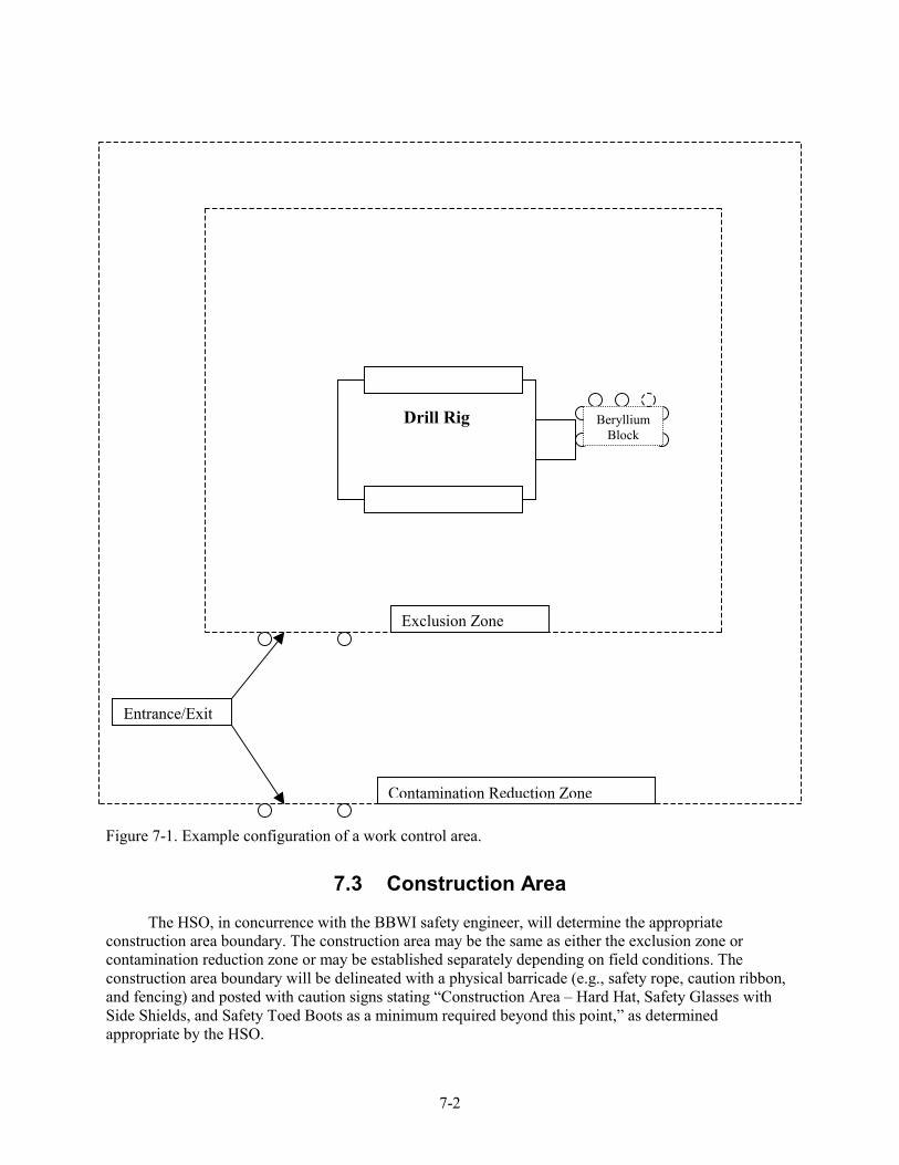
7-2
Figure 7-1. Example configuration of a work control area.
7.3 Construction Area
The HSO, in concurrence with the BBWI safety engineer, will determine the appropriate construction area boundary. The construction area may be the same as either the exclusion zone or contamination reduction zone or may be established separately depending on field conditions. The construction area boundary will be delineated with a physical barricade (e.g., safety rope, caution ribbon, and fencing) and posted with caution signs stating “Construction Area – Hard Hat, Safety Glasses with Side Shields, and Safety Toed Boots as a minimum required beyond this point,” as determined appropriate by the HSO.
Contamination Reduction Zone
Entrance/Exit
Drill Rig
Beryllium Block
Exclusion Zone
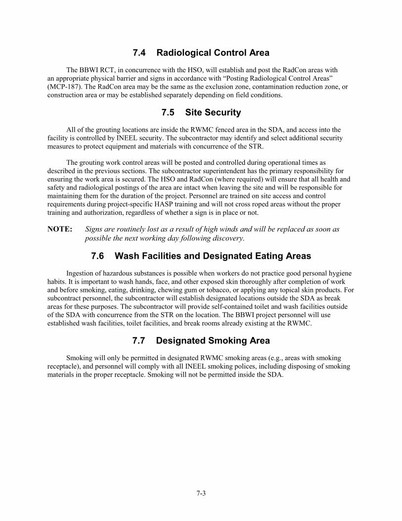
7-3
7.4 Radiological Control Area
The BBWI RCT, in concurrence with the HSO, will establish and post the RadCon areas with an appropriate physical barrier and signs in accordance with “Posting Radiological Control Areas” (MCP-187). The RadCon area may be the same as the exclusion zone, contamination reduction zone, or construction area or may be established separately depending on field conditions.
7.5 Site Security
All of the grouting locations are inside the RWMC fenced area in the SDA, and access into the facility is controlled by INEEL security. The subcontractor may identify and select additional security measures to protect equipment and materials with concurrence of the STR.
The grouting work control areas will be posted and controlled during operational times as described in the previous sections. The subcontractor superintendent has the primary responsibility for ensuring the work area is secured. The HSO and RadCon (where required) will ensure that all health and safety and radiological postings of the area are intact when leaving the site and will be responsible for maintaining them for the duration of the project. Personnel are trained on site access and control requirements during project-specific HASP training and will not cross roped areas without the proper training and authorization, regardless of whether a sign is in place or not.
NOTE: Signs are routinely lost as a result of high winds and will be replaced as soon as possible the next working day following discovery.
7.6 Wash Facilities and Designated Eating Areas
Ingestion of hazardous substances is possible when workers do not practice good personal hygiene habits. It is important to wash hands, face, and other exposed skin thoroughly after completion of work and before smoking, eating, drinking, chewing gum or tobacco, or applying any topical skin products. For subcontract personnel, the subcontractor will establish designated locations outside the SDA as break areas for these purposes. The subcontractor will provide self-contained toilet and wash facilities outside of the SDA with concurrence from the STR on the location. The BBWI project personnel will use established wash facilities, toilet facilities, and break rooms already existing at the RWMC.
7.7 Designated Smoking Area
Smoking will only be permitted in designated RWMC smoking areas (e.g., areas with smoking receptacle), and personnel will comply with all INEEL smoking polices, including disposing of smoking materials in the proper receptacle. Smoking will not be permitted inside the SDA.

7-4
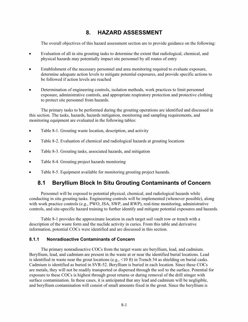
8-1
8. HAZARD ASSESSMENT
The overall objectives of this hazard assessment section are to provide guidance on the following:
• Evaluation of all in situ grouting tasks to determine the extent that radiological, chemical, and physical hazards may potentially impact site personnel by all routes of entry
• Establishment of the necessary personnel and area monitoring required to evaluate exposure, determine adequate action levels to mitigate potential exposures, and provide specific actions to be followed if action levels are reached
• Determination of engineering controls, isolation methods, work practices to limit personnel exposure, administrative controls, and appropriate respiratory protection and protective clothing to protect site personnel from hazards.
The primary tasks to be performed during the grouting operations are identified and discussed in this section. The tasks, hazards, hazards mitigation, monitoring and sampling requirements, and monitoring equipment are evaluated in the following tables:
• Table 8-1. Grouting waste location, description, and activity
• Table 8-2. Evaluation of chemical and radiological hazards at grouting locations
• Table 8-3. Grouting tasks, associated hazards, and mitigation
• Table 8-4. Grouting project hazards monitoring
• Table 8-5. Equipment available for monitoring grouting project hazards.
8.1 Beryllium Block In Situ Grouting Contaminants of Concern
Personnel will be exposed to potential physical, chemical, and radiological hazards while conducting in situ grouting tasks. Engineering controls will be implemented (whenever possible), along with work practice controls (e.g., PWO, JSA, SWP, and RWP), real-time monitoring, administrative controls, and site-specific hazard training to further identify and mitigate potential exposures and hazards.
Table 8-1 provides the approximate location in each target soil vault row or trench with a description of the waste form and the nuclide activity in curies. From this table and derivative information, potential COCs were identified and are discussed in this section.
8.1.1 Nonradioactive Contaminants of Concern
The primary nonradioactive COCs from the target waste are beryllium, lead, and cadmium. Beryllium, lead, and cadmium are present in the waste at or near the identified burial locations. Lead is identified in waste near the grout locations (e.g., <10 ft) in Trench 54 as shielding on burial casks. Cadmium is identified as buried in SVR-52. Beryllium is buried in each location. Since these COCs are metals, they will not be readily transported or dispersed through the soil to the surface. Potential for exposure to these COCs is highest through grout returns or during removal of the drill stinger with surface contamination. In these cases, it is anticipated that any lead and cadmium will be negligible, and beryllium contamination will consist of small amounts fixed in the grout. Since the beryllium is
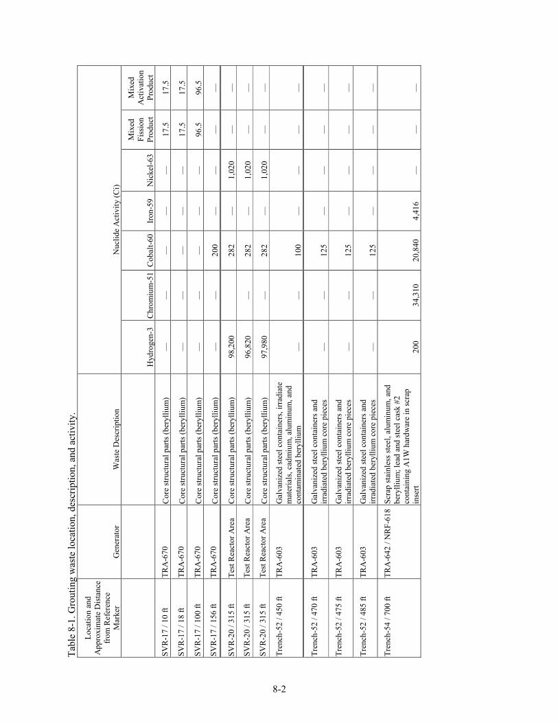
8-2
Tabl
e 8-
1. G
rout
ing
was
te lo
catio
n, d
escr
iptio
n, a
nd a
ctiv
ity.
Loca
tion
and
App
roxi
mat
e D
ista
nce
from
Ref
eren
ce
Mar
ker
Gen
erat
or
Was
te D
escr
iptio
n N
uclid
e A
ctiv
ity (C
i)
H
ydro
gen-
3 C
hrom
ium
-51
Cob
alt-6
0Ir
on-5
9 N
icke
l-63
Mix
ed
Fiss
ion
Prod
uct
Mix
ed
Act
ivat
ion
Prod
uct
SVR
-17
/ 10
ft TR
A-6
70
Cor
e st
ruct
ural
par
ts (b
eryl
lium
) —
—
—
—
—
17
.5
17.5
SVR
-17
/ 18
ft TR
A-6
70
Cor
e st
ruct
ural
par
ts (b
eryl
lium
) —
—
—
—
—
17
.5
17.5
SVR
-17
/ 100
ft
TRA
-670
C
ore
stru
ctur
al p
arts
(ber
ylliu
m)
—
—
—
—
—
96.5
96
.5
SVR
-17
/ 156
ft
TRA
-670
C
ore
stru
ctur
al p
arts
(ber
ylliu
m)
—
—
200
—
—
—
—
SVR
-20
/ 315
ft
Test
Rea
ctor
Are
a C
ore
stru
ctur
al p
arts
(ber
ylliu
m)
98,2
00
28
2 —
1,
020
—
—
SVR
-20
/ 315
ft
Test
Rea
ctor
Are
a C
ore
stru
ctur
al p
arts
(ber
ylliu
m)
96,8
20
—
282
—
1,02
0 —
—
SVR
-20
/ 315
ft
Test
Rea
ctor
Are
a C
ore
stru
ctur
al p
arts
(ber
ylliu
m)
97,9
80
—
282
—
1,02
0 —
—
Tren
ch-5
2 / 4
50 ft
TR
A-6
03
Gal
vani
zed
stee
l con
tain
ers,
irrad
iate
m
ater
ials
, cad
miu
m, a
lum
inum
, and
co
ntam
inat
ed b
eryl
lium
—
—
10
0 —
—
—
—
Tren
ch-5
2 / 4
70 ft
TR
A-6
03
Gal
vani
zed
stee
l con
tain
ers a
nd
irrad
iate
d be
rylli
um c
ore
piec
es
—
—
125
—
—
—
—
Tren
ch-5
2 / 4
75 ft
TR
A-6
03
Gal
vani
zed
stee
l con
tain
ers a
nd
irrad
iate
d be
rylli
um c
ore
piec
es
—
—
125
—
—
—
—
Tren
ch-5
2 / 4
85 ft
TR
A-6
03
Gal
vani
zed
stee
l con
tain
ers a
nd
irrad
iate
d be
rylli
um c
ore
piec
es
—
—
125
—
—
—
—
Tren
ch-5
4 / 7
00 ft
TR
A-6
42 /
NR
F-61
8 Sc
rap
stai
nles
s ste
el, a
lum
inum
, and
be
rylli
um; l
ead
and
stee
l cas
k #2
co
ntai
ning
A1W
har
dwar
e in
scra
p in
sert
200
34,3
10
20,8
40
4,41
6 —
—
—
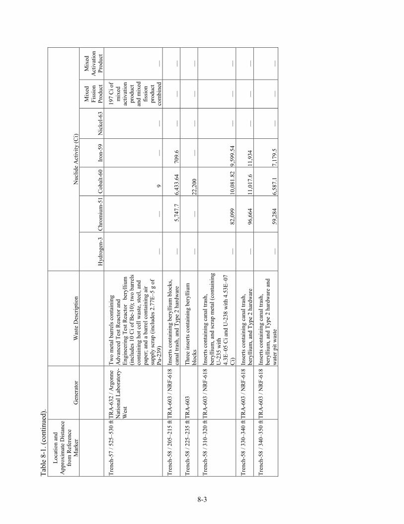
Tabl
e 8-
1. (c
ontin
ued)
.
8-3
Loca
tion
and
App
roxi
mat
e D
ista
nce
from
Ref
eren
ce
Mar
ker
Gen
erat
or
Was
te D
escr
iptio
n N
uclid
e A
ctiv
ity (C
i)
H
ydro
gen-
3 C
hrom
ium
-51
Cob
alt-6
0Ir
on-5
9 N
icke
l-63
Mix
ed
Fiss
ion
Prod
uct
Mix
ed
Act
ivat
ion
Prod
uct
Tren
ch-5
7 / 5
25–5
30 ft
TR
A-6
32 /
Arg
onne
N
atio
nal L
abor
ator
y-W
est
Two
met
al b
arre
ls c
onta
inin
g A
dvan
ced
Test
Rea
ctor
and
En
gine
erin
g Te
st R
eact
or
bery
llium
(in
clud
es 1
0 C
i of B
e-10
); tw
o ba
rrel
s co
ntai
ning
hot
cel
l was
te, s
teel
, and
pa
per;
and
a ba
rrel
con
tain
ing
air
supp
ly sc
rap
(incl
udes
2.7
7E–5
g o
f Pu
-239
) —
—
9
—
—
197
Ci o
f m
ixed
ac
tivat
ion
prod
uct
and
mix
ed
fissi
on
prod
uct
com
bine
d—
Tren
ch-5
8 / 2
05–2
15 ft
TR
A-6
03 /
NR
F-61
8 In
serts
con
tain
ing
bery
llium
blo
cks,
cana
l tra
sh, a
nd T
ype
2 ha
rdw
are
—
5,74
7.7
6,43
3.64
70
9.6
—
—
—
Tren
ch-5
8 / 2
25–2
35 ft
TR
A-6
03
Thre
e in
serts
con
tain
ing
bery
llium
bl
ocks
—
—
22
,200
—
—
—
—
Tren
ch-5
8 / 3
10–3
20 ft
TR
A-6
03 /
NR
F-61
8 In
serts
con
tain
ing
cana
l tra
sh,
bery
llium
, and
scra
p m
etal
(con
tain
ing
U-2
35 w
ith
4.3E
–05
Ci a
nd U
-238
with
4.5
3E–0
7 C
i) —
82
,099
10
,081
.82
9,59
9.54
—
—
—
Tren
ch-5
8 / 3
30–3
40 ft
TR
A-6
03 /
NR
F-61
8 In
serts
con
tain
ing
cana
l tra
sh,
bery
llium
, and
Typ
e 2
hard
war
e —
96
,664
11
,017
.6
11,9
34
—
—
—
Tren
ch-5
8 / 3
40–3
50 ft
TR
A-6
03 /
NR
F-61
8 In
serts
con
tain
ing
cana
l tra
sh,
bery
llium
, and
Typ
e 2
hard
war
e an
d w
ater
pit
was
te
—
59,2
84
6,58
7.1
7,17
9.5
—
—
—
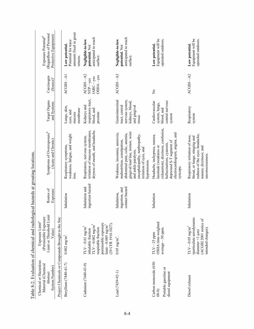
8-4
Tabl
e 8-
2. E
valu
atio
n of
che
mic
al a
nd ra
diol
ogic
al h
azar
ds a
t gro
utin
g lo
catio
ns.
Che
mic
al o
r Haz
ardo
us
Mat
eria
l (C
hem
ical
A
bstra
ct
Syst
em N
umbe
r)
Expo
sure
Lim
ita
(Per
mis
sibl
e Ex
posu
re
Lim
it or
Thr
esho
ld L
imit
Val
ue)
Rou
tes o
f Ex
posu
re
Sym
ptom
s of O
vere
xpos
ureb
(Acu
te a
nd C
hron
ic)
Targ
et O
rgan
s an
d Sy
stem
s C
arci
noge
n (S
ourc
e)c
Expo
sure
Pot
entia
ld
(Reg
ardl
ess o
f Per
sona
l Pr
otec
tive
Equi
pmen
t)
Proj
ect C
hem
ical
s or C
ompo
unds
Bro
ught
to th
e Si
te
Ber
ylliu
m (7
440-
41-7
) 0.
002
mg/
m3 .
Inha
latio
n R
espi
rato
ry sy
mpt
oms,
wea
knes
s, fa
tigue
, and
wei
ght
loss
.
Lung
s, sk
in,
eyes
, and
m
ucou
s m
embr
ane
AC
GIH
—A
1 L
ow p
oten
tial.
Pote
ntia
l for
trac
e am
ount
s fix
ed in
gro
ut
retu
rns.
Cad
miu
m (7
440-
43-9
) TL
V—
0.01
mg/
m3
inha
labl
e fra
ctio
n TL
V—
0.00
2 m
g/m
3
resp
irabl
e fra
ctio
n pe
rmis
sibl
e ex
posu
re
limit—
0.00
5 m
g/m
3
(29
CFR
191
0.10
27).
Inha
latio
n an
d in
gest
ion
haza
rd
Res
pira
tory
, ner
vous
syst
em,
irrita
tion
of m
ucou
s mem
bran
es,
dryn
ess o
f mou
th, a
nd h
eada
che.
Kid
neys
and
re
spira
tory
trac
t, bl
ood,
and
pr
osta
te
AC
GIH
—A
2 N
TP—
yes
IAR
C—
yes
OSH
A—
yes
Neg
ligib
le-t
o-lo
w
pote
ntia
l. N
ot
antic
ipat
ed to
reac
h su
rface
.
Lead
(743
9-92
-1)
0.05
mg/
m3 .
Inha
latio
n,
inge
stio
n, a
nd
cont
act h
azar
d
Wea
knes
s, in
som
nia,
ano
rexi
a,
mal
nutri
tion,
con
stipa
tion,
ab
dom
inal
pai
n, c
olic
, ane
mia
, gi
ngiv
al le
ad li
ne, t
rem
or, w
rist
and
ankl
e pa
raly
sis,
ence
phal
opat
hy, n
ephr
opat
hy,
irrita
tion
of e
yes,
and
hypo
tens
ion.
Gas
troin
test
inal
tra
ct, c
entra
l ne
rvou
s sys
tem
, ki
dney
s, bl
ood,
an
d gi
ngiv
al
tissu
e
AC
GIH
—A
3 N
eglig
ible
-to-
low
po
tent
ial.
Not
an
ticip
ated
to re
ach
surfa
ce.
Car
bon
mon
oxid
e (6
30-
08-0
)
Porta
ble
gaso
line
or
dies
el e
quip
men
t
TLV
—25
ppm
O
SHA
tim
e-w
eigh
ted
aver
age—
50 p
pm.
Inha
latio
n H
eada
che,
tach
ypne
a, n
ause
a,
lass
itude
(wea
knes
s or
exha
ustio
n), d
izzi
ness
, con
fusi
on,
hallu
cina
tions
, cya
nosi
s, de
pres
sed
S-T
segm
ent o
f el
ectro
card
iogr
am, a
ngin
a, a
nd
sync
ope.
Car
diov
ascu
lar
syst
em, l
ungs
, bl
ood,
and
ce
ntra
l ner
vous
sy
stem
No
Low
pot
entia
l. Eq
uipm
ent w
ill b
e op
erat
ed o
utdo
ors.
Die
sel e
xhau
st
TLV
—0.
05 m
g/m
3 (p
artic
ulat
e ae
rody
nam
ic
diam
eter
<1
µm)
(AC
GIH
200
1 no
tice
of
inte
nded
cha
nges
).
Inha
latio
n R
espi
rato
ry ir
ritat
ion
of n
ose,
th
roat
, or l
ungs
; stin
ging
and
re
dnes
s of t
he e
yes;
hea
dach
e;
naus
ea; d
izzi
ness
; and
un
cons
ciou
snes
s.
Res
pira
tory
sy
stem
A
CG
IH—
A2
Low
pot
entia
l. Eq
uipm
ent w
ill b
e op
erat
ed o
utdo
ors.
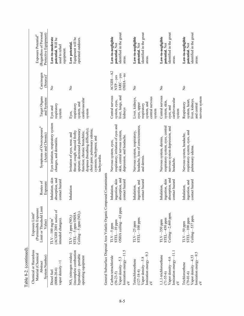
Tabl
e 8-
2. (c
ontin
ued)
.
8-5
Che
mic
al o
r Haz
ardo
us
Mat
eria
l (C
hem
ical
A
bstra
ct
Syst
em N
umbe
r)
Expo
sure
Lim
ita
(Per
mis
sibl
e Ex
posu
re
Lim
it or
Thr
esho
ld L
imit
Val
ue)
Rou
tes o
f Ex
posu
re
Sym
ptom
s of O
vere
xpos
ureb
(Acu
te a
nd C
hron
ic)
Targ
et O
rgan
s an
d Sy
stem
s C
arci
noge
n (S
ourc
e)c
Expo
sure
Pot
entia
ld
(Reg
ardl
ess o
f Per
sona
l Pr
otec
tive
Equi
pmen
t)
Die
sel f
uel
(800
8-20
-6)
vapo
r den
sity
–>1
TLV
—10
0 m
g/m
3
(AC
GIH
200
1 no
tice
of
inte
nded
cha
nges
).
Inha
latio
n, sk
in
abso
rptio
n, a
nd
cont
act h
azar
d
Eyes
irrit
atio
n, re
spira
tory
syst
em
chan
ges,
and
derm
atiti
s. Ey
es a
nd
resp
irato
ry
syst
em
No
Low
-to-
mod
erat
e po
tent
ial.
Will
be
used
to re
fuel
eq
uipm
ent.
NO
x (n
itrog
en o
xide
s)
(inco
mpl
ete
com
bust
ion
bypr
oduc
t)—po
rtabl
e op
erat
ing
equi
pmen
t
TLV
—3
ppm
(NO
2)
STEL
—5
ppm
OSH
A
Cei
ling—
5 pp
m (N
O2)
.
Inha
latio
n Ir
ritat
ion
of e
yes,
nose
, and
th
roat
; cou
gh; m
ucoi
d fro
thy
sput
um; d
ecre
ased
pul
mon
ary
func
tion;
chr
onic
bro
nchi
tis;
dysp
nea
(bre
athi
ng d
iffic
ulty
); ch
est p
ain;
pul
mon
ary
edem
a;
cyan
osis
; tac
hypn
ea; a
nd
tach
ycar
dia.
Eyes
, re
spira
tory
sy
stem
, and
ca
rdio
vasc
ular
sy
stem
No
Low
pot
entia
l. Eq
uipm
ent w
ill b
e op
erat
ed o
utdo
ors.
Gen
eral
Sub
surfa
ce D
ispo
sal A
rea
Vol
atile
Org
anic
Com
poun
d Co
ntam
inan
ts
Car
bon
tetra
chlo
ride
(56-
23-5
) V
apor
den
sity
—5.
3 Io
niza
tion
ener
gy—
11.5
eV
TLV
—5
ppm
ST
EL—
10 p
pm
OSH
A c
eilin
g—63
ppm
.
Inha
latio
n,
inge
stio
n, sk
in
abso
rptio
n, a
nd
cont
act h
azar
d
Ner
vous
syst
em, e
yes,
resp
irato
ry; i
rrita
tion
of e
yes a
nd
skin
, cen
tral n
ervo
us sy
stem
, de
pres
sion
, and
hea
dach
e.
Cen
tral n
ervo
us
syst
em, e
yes,
liver
, lun
gs, a
nd
kidn
eys
AC
GIH
—A
2 N
TP—
yes
IAR
C—
yes
OSH
A—
no
Low
-to-
negl
igib
le
pote
ntia
l. N
ot
iden
tifie
d in
the
grou
t ar
eas.
Tetra
chlo
roet
hene
(1
27-1
8-4)
V
apor
den
sity
—5.
8 Io
niza
tion
ener
gy—
9.3
eV
TLV
—25
ppm
ST
EL—
100
ppm
. In
hala
tion,
in
gest
ion,
and
co
ntac
t haz
ard
Ner
vous
syst
em, r
espi
rato
ry,
head
ache
, los
s of c
onsc
ious
ness
, an
d de
rmis
.
Live
r, ki
dney
s, ey
es, u
pper
re
spira
tory
sy
stem
, and
ce
ntra
l ner
vous
sy
stem
No
Low
-to-
negl
igib
le
pote
ntia
l. N
ot
iden
tifie
d in
the
grou
t ar
eas.
1,1,
1-tri
chlo
roet
hane
(7
1-55
-6)
Vap
or d
ensi
ty—
4.6
Ioni
zatio
n en
ergy
—11
.1
eV
TLV
—35
0 pp
m
STEL
—45
0 pp
m
Cei
ling—
2,46
0 pp
m.
Inha
latio
n,
inge
stio
n, sk
in
abso
rptio
n, a
nd
cont
act h
azar
d
Ner
vous
syst
em, d
erm
is,
resp
irato
ry sy
stem
, eye
s, ce
ntra
l ne
rvou
s sys
tem
dep
ress
ion,
and
he
adac
he.
Cen
tral n
ervo
us
syst
em, s
kin,
ey
es, a
nd
card
iova
scul
ar
syst
em
No
Low
-to-
negl
igib
le
pote
ntia
l. N
ot
iden
tifie
d in
the
grou
t ar
eas.
Tric
hlor
oeth
ene
(79-
01-6
) V
apor
den
sity
—4.
53
Ioni
zatio
n en
ergy
—9.
5 eV
TLV
—50
ppm
ST
EL—
100
ppm
C
eilin
g—53
7 pp
m.
Inha
latio
n,
inge
stio
n, a
nd
cont
act h
azar
d
Ner
vous
syst
em, h
eada
che,
re
spira
tory
syst
em, e
yes,
and
pulm
onar
y ed
ema.
Res
pira
tory
sy
stem
, hea
rt,
liver
, kid
neys
, an
d ce
ntra
l ne
rvou
s sys
tem
No
Low
-to-
negl
igib
le
pote
ntia
l. N
ot
iden
tifie
d in
the
grou
t ar
eas.
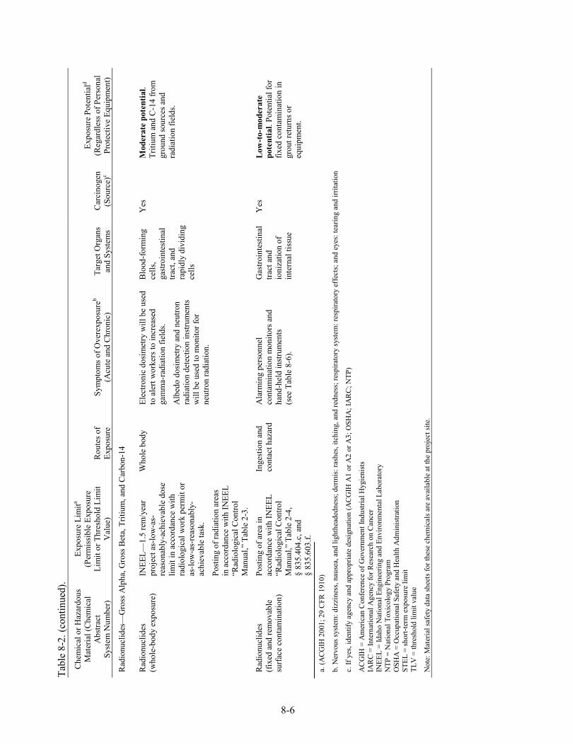
Tabl
e 8-
2. (c
ontin
ued)
.
8-6
Che
mic
al o
r Haz
ardo
us
Mat
eria
l (C
hem
ical
A
bstra
ct
Syst
em N
umbe
r)
Expo
sure
Lim
ita
(Per
mis
sibl
e Ex
posu
re
Lim
it or
Thr
esho
ld L
imit
Val
ue)
Rou
tes o
f Ex
posu
re
Sym
ptom
s of O
vere
xpos
ureb
(Acu
te a
nd C
hron
ic)
Targ
et O
rgan
s an
d Sy
stem
s C
arci
noge
n (S
ourc
e)c
Expo
sure
Pot
entia
ld
(Reg
ardl
ess o
f Per
sona
l Pr
otec
tive
Equi
pmen
t)
Rad
ionu
clid
es—
Gro
ss A
lpha
, Gro
ss B
eta,
Trit
ium
, and
Car
bon-
14
Rad
ionu
clid
es
(who
le-b
ody
expo
sure
) IN
EEL—
1.5
rem
/yea
r pr
ojec
t as-
low
-as-
reas
onab
ly-a
chie
vabl
e do
se
limit
in a
ccor
danc
e w
ith
radi
olog
ical
wor
k pe
rmit
or
as-lo
w-a
s-re
ason
ably
-ac
hiev
able
task
.
Post
ing
of ra
diat
ion
area
s in
acc
orda
nce
with
INEE
L “R
adio
logi
cal C
ontro
l M
anua
l,” T
able
2-3
.
Who
le b
ody
Elec
troni
c do
sim
etry
will
be
used
to
ale
rt w
orke
rs to
incr
ease
d ga
mm
a-ra
diat
ion
field
s.
Alb
edo
dosi
met
ry a
nd n
eutro
n ra
diat
ion
dete
ctio
n in
stru
men
ts
will
be
used
to m
onito
r for
ne
utro
n ra
diat
ion.
Blo
od-fo
rmin
g ce
lls,
gast
roin
test
inal
tra
ct, a
nd
rapi
dly
divi
ding
ce
lls
Yes
M
oder
ate
pote
ntia
l. Tr
itium
and
C-1
4 fro
m
grou
nd so
urce
s and
ra
diat
ion
field
s.
Rad
ionu
clid
es
(fixe
d an
d re
mov
able
su
rface
con
tam
inat
ion)
Post
ing
of a
rea
in
acco
rdan
ce w
ith IN
EEL
“Rad
iolo
gica
l Con
trol
Man
ual,”
Tab
le 2
-4,
§ 83
5.40
4.c,
and
§
835.
603.
f.
Inge
stio
n an
d co
ntac
t haz
ard
Ala
rmin
g pe
rson
nel
cont
amin
atio
n m
onito
rs a
nd
hand
-hel
d in
stru
men
ts
(see
Tab
le 8
-6).
Gas
troin
test
inal
tra
ct a
nd
ioni
zatio
n of
in
tern
al ti
ssue
Yes
L
ow-t
o-m
oder
ate
pote
ntia
l. Po
tent
ial f
or
fixed
con
tam
inat
ion
in
grou
t ret
urns
or
equi
pmen
t.
a. (A
CG
IH 2
001;
29
CFR
191
0)
b. N
ervo
us sy
stem
: diz
zine
ss, n
ause
a, a
nd li
ghth
eade
dnes
s; d
erm
is: r
ashe
s, itc
hing
, and
redn
ess;
resp
irato
ry s
yste
m: r
espi
rato
ry e
ffec
ts; a
nd e
yes:
tear
ing
and
irrita
tion
c. If
yes
, ide
ntify
age
ncy
and
appr
opria
te d
esig
natio
n (A
CG
IH A
1 or
A2
or A
3; O
SHA
; IA
RC
; NTP
)
AC
GIH
= A
mer
ican
Con
fere
nce
of G
over
nmen
t Ind
ustri
al H
ygie
nist
s IA
RC
= In
tern
atio
nal A
genc
y fo
r Res
earc
h on
Can
cer
INEE
L =
Idah
o N
atio
nal E
ngin
eerin
g an
d En
viro
nmen
tal L
abor
ator
y N
TP =
Nat
iona
l Tox
icol
ogy
Prog
ram
O
SHA
= O
ccup
atio
nal S
afet
y an
d H
ealth
Adm
inis
tratio
n ST
EL =
shor
t-ter
m e
xpos
ure
limit
TLV
= th
resh
old
limit
valu
e
Not
e: M
ater
ial s
afet
y da
ta sh
eets
for t
hese
che
mic
als a
re a
vaila
ble
at th
e pr
ojec
t site
.
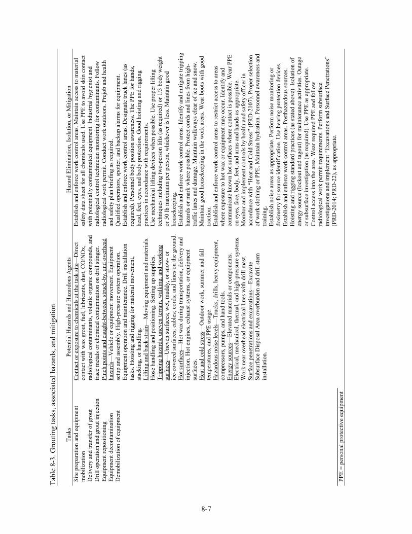
8-7
Tabl
e 8-
3. G
rout
ing
task
s, as
soci
ated
haz
ards
, and
miti
gatio
n.
Task
s Po
tent
ial H
azar
ds a
nd H
azar
dous
Age
nts
Haz
ard
Elim
inat
ion,
Isol
atio
n, o
r Miti
gatio
n Si
te p
repa
ratio
n an
d eq
uipm
ent
mob
iliza
tion
Del
iver
y an
d tra
nsfe
r of g
rout
D
rill o
pera
tion
and
grou
t inj
ectio
n Eq
uipm
ent r
epos
ition
ing
Equi
pmen
t dec
onta
min
atio
n D
emob
iliza
tion
of e
quip
men
t
Con
tact
or e
xpos
ure
to c
hem
ical
s at t
he ta
sk si
te—
Dire
ct
cont
act w
ith w
ax g
rout
, fue
l, lu
bric
ants
, dus
t, C
O/N
Ox,
ra
diol
ogic
al c
onta
min
ants
, vol
atile
org
anic
com
poun
ds, a
nd
trace
met
als o
r che
mic
al c
onta
min
atio
n on
dril
l stin
ger.
Pinc
h po
ints
and
cau
ght-b
etw
een,
stru
ck-b
y, a
nd o
verh
ead
haza
rds—
Veh
icle
or e
quip
men
t mov
emen
t. Eq
uipm
ent
setu
p an
d as
sem
bly.
Hig
h-pr
essu
re sy
stem
ope
ratio
n.
Equi
pmen
t ope
ratio
n an
d m
aint
enan
ce. D
rill i
nsta
llatio
n ta
sks.
Hoi
stin
g an
d rig
ging
for m
ater
ial m
ovem
ent,
stac
king
, or h
andl
ing.
Li
fting
and
bac
k st
rain
—M
ovin
g eq
uipm
ent a
nd m
ater
ials
. H
ose
hand
ling
and
posi
tioni
ng. S
ettin
g up
supp
lies.
Trip
ping
haz
ards
, une
ven
terr
ain,
wal
king
, and
wor
king
su
rface
s—U
neve
n su
rfac
es; w
et, m
uddy
, or s
now
- or
ice-
cove
red
surfa
ces;
cab
les;
cor
ds; a
nd li
nes o
n th
e gr
ound
. H
ot su
rface
s—H
ot w
ax d
urin
g tra
nspo
rtatio
n, d
eliv
ery
and
inje
ctio
n. H
ot e
ngin
es, e
xhau
st sy
stem
s, or
equ
ipm
ent
surfa
ces.
Hea
t and
col
d st
ress
—O
utdo
or w
ork,
sum
mer
and
fall
tem
pera
ture
s, an
d PP
E us
age.
H
azar
dous
noi
se le
vels
—Tr
ucks
, dril
ls, h
eavy
equ
ipm
ent,
com
pres
sors
, pum
ps, a
nd h
and
tool
s. En
ergy
sour
ces—
Elev
ated
mat
eria
ls o
r com
pone
nts.
Elec
trica
l, m
echa
nica
l, th
erm
al, a
nd h
igh-
pres
sure
syst
ems.
Wor
k ne
ar o
verh
ead
elec
trica
l lin
es w
ith d
rill m
ast.
Surfa
ce p
enet
ratio
ns a
nd e
xcav
atio
ns—
Exca
vate
Su
bsur
face
Dis
posa
l Are
a ov
erbu
rden
and
dril
l ste
m
inst
alla
tion.
Esta
blis
h an
d en
forc
e w
ork
cont
rol a
reas
. Mai
ntai
n ac
cess
to m
ater
ial
safe
ty d
ata
shee
t for
all
chem
ical
s use
d. U
se P
PE to
avo
id sk
in c
onta
ct
with
pot
entia
lly c
onta
min
ated
equ
ipm
ent.
Indu
stria
l hyg
ieni
st a
nd
radi
olog
ical
con
trol t
echn
icia
n m
onito
ring
for c
onta
min
ants
. Fol
low
ra
diol
ogic
al w
ork
perm
it. C
ondu
ct w
ork
outd
oors
. Pre
job
and
heal
th
and
safe
ty p
lan
brie
fing
as re
quire
d.
Qua
lifie
d op
erat
ors,
spot
ter,
and
back
up a
larm
s for
equ
ipm
ent.
Esta
blis
h an
d en
forc
e w
ork
cont
rol a
reas
. Des
igna
te tr
uck
lane
s (as
re
quire
d). P
erso
nnel
bod
y po
sitio
n aw
aren
ess.
The
PPE
for h
ands
, he
ad, f
eet,
eyes
, and
bod
y pr
otec
tion.
Goo
d ho
istin
g an
d rig
ging
pr
actic
es in
acc
orda
nce
with
requ
irem
ents
. U
se m
echa
nica
l lift
ing
devi
ces w
hen
poss
ible
. Use
pro
per l
iftin
g te
chni
ques
incl
udin
g tw
o-pe
rson
lifts
(as r
equi
red)
or 1
/3 b
ody
wei
ght
or 5
0 lb
max
imum
per
per
son,
whi
chev
er is
less
. Mai
ntai
n go
od
hous
ekee
ping
. Es
tabl
ish
and
enfo
rce
wor
k co
ntro
l are
as. I
dent
ify a
nd m
itiga
te tr
ippi
ng
haza
rds o
r mar
k w
here
pos
sibl
e. P
rote
ct c
ords
and
line
s fro
m h
igh-
traffi
c la
nes a
nd d
amag
e. M
aint
ain
wal
kway
s cle
ar o
f ice
and
snow
. M
aint
ain
good
hou
seke
epin
g in
the
wor
k ar
eas.
Wea
r boo
ts w
ith g
ood
tract
ion.
Es
tabl
ish
and
enfo
rce
wor
k co
ntro
l are
as to
rest
rict a
cces
s to
area
s w
here
exp
osur
e to
hot
wax
or e
quip
men
t may
occ
ur. I
dent
ify a
nd
com
mun
icat
e kn
own
hot s
urfa
ces w
here
con
tact
is p
ossi
ble.
Wea
r PPE
on
eye
s, fa
ce, b
ody,
feet
, and
arm
s and
han
ds a
s app
ropr
iate
. M
onito
r and
impl
emen
t con
trols
by
heal
th a
nd sa
fety
offi
cer i
n ac
cord
ance
with
“H
eat a
nd C
old
Stre
ss”
(PR
D-2
107)
. Pro
per s
elec
tion
of w
ork
clot
hing
or P
PE. M
aint
ain
hydr
atio
n. P
erso
nnel
aw
aren
ess a
nd
train
ing.
Es
tabl
ish
nois
e ar
eas a
s app
ropr
iate
. Per
form
noi
se m
onito
ring
or
dosi
met
ry fo
r sou
rce
iden
tific
atio
n. U
se h
earin
g pr
otec
tion
devi
ces.
Esta
blis
h an
d en
forc
e w
ork
cont
rol a
reas
. Pos
thaz
ardo
us so
urce
s. H
oist
ing
and
riggi
ng st
anda
rd p
ract
ices
(as s
tate
d ab
ove)
. Iso
latio
n of
en
ergy
sour
ce (l
ocko
ut a
nd ta
gout
) for
mai
nten
ance
act
iviti
es. O
utag
e or
subs
urfa
ce in
vest
igat
ion
(as r
equi
red)
. Use
PPE
as a
ppro
pria
te.
Con
trol a
cces
s int
o th
e ar
ea. W
ear r
equi
red
PPE
and
follo
w
radi
olog
ical
wor
k pe
rmit
requ
irem
ents
. Per
form
subs
urfa
ce
inve
stig
atio
ns a
nd im
plem
ent “
Exca
vatio
ns a
nd S
urfa
ce P
enet
ratio
ns”
(PR
D-2
014;
PR
D-2
2), a
s app
ropr
iate
. PP
E =
pers
onal
pro
tect
ive
equi
pmen
t
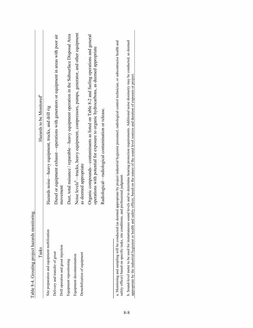
8-8
Tabl
e 8-
4. G
rout
ing
proj
ect h
azar
ds m
onito
ring.
Task
s H
azar
ds to
be
Mon
itore
da Si
te p
repa
ratio
n an
d eq
uipm
ent m
obili
zatio
n
Del
iver
y an
d tra
nsfe
r of g
rout
Dril
l ope
ratio
n an
d gr
out i
njec
tion
Equi
pmen
t rep
ositi
onin
g
Equi
pmen
t dec
onta
min
atio
n
Dem
obili
zatio
n of
equ
ipm
ent
Haz
ards
noi
se—
heav
y eq
uipm
ent,
truck
s, an
d dr
ill ri
g
Die
sel o
r equ
ipm
ent e
xhau
st—
oper
atio
ns w
ith g
ener
ator
s or e
quip
men
t in
area
s with
poo
r air
mov
emen
t
Dus
t, to
tal n
uisa
nce
/ rep
arab
le—
heav
y eq
uipm
ent o
pera
tion
in th
e Su
bsur
face
Dis
posa
l Are
a
Noi
se le
vels
b —tru
cks,
heav
y eq
uipm
ent,
com
pres
sors
, pum
ps, g
ener
ator
, and
oth
er e
quip
men
t as
dee
med
app
ropr
iate
Org
anic
com
poun
ds—
cont
amin
ants
as l
iste
d on
Tab
le 8
-2 a
nd fu
elin
g op
erat
ions
and
gen
eral
op
erat
ions
with
pot
entia
l for
exp
osur
e to
org
anic
hyd
roca
rbon
s, as
dee
med
app
ropr
iate
Rad
iolo
gica
l—ra
diol
ogic
al c
onta
min
atio
n or
rele
ase.
a. M
onito
ring
and
sam
plin
g w
ill b
e co
nduc
ted
(as d
eem
ed a
ppro
pria
te b
y pr
ojec
t ind
ustri
al h
ygie
nist
per
sonn
el, r
adio
logi
cal c
ontro
l tec
hnic
ian,
or s
ubco
ntra
ctor
hea
lth a
nd
safe
ty o
ffice
r) b
ased
on
spec
ific
task
s, si
te c
ondi
tions
, and
pro
fess
iona
l jud
gmen
t.
b. S
ound
-leve
l met
er to
be
used
for i
nsta
ntan
eous
soun
d le
vels
and
to d
eter
min
e he
arin
g pr
otec
tion
requ
irem
ents
. Add
ition
al n
oise
dos
imet
ry m
ay b
e co
nduc
ted,
as d
eem
ed
appr
opria
te b
y th
e in
dust
rial h
ygie
nist
or h
ealth
and
safe
ty o
ffice
r, ba
sed
on th
e na
ture
of t
he so
und
leve
l sou
rces
and
dur
atio
n of
exp
osur
e or
pro
ject
.
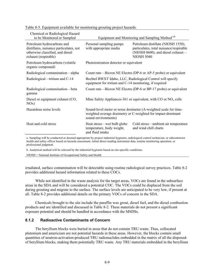
8-9
Table 8-5. Equipment available for monitoring grouting project hazards. Chemical or Radiological Hazard
to be Monitored or Sampled Equipment and Monitoring and Sampling Method a,b
Petroleum hydrocarbons and distillates, nuisance particulates, not otherwise classified, and diesel exhaust (respirable)
Personal sampling pumps with appropriate media
Petroleum distillate (NIOSH 1550), particulates, total nuisance/respirable (NIOSH 0600), and diesel exhaust—NIOSH 5040
Petroleum hydrocarbons (volatile organic compound)
Photoionization detector or equivalent
Radiological contamination—alpha Count rate—Bicron NE Electra (DP-6 or AP-5 probe) or equivalent Radiological—tritium and C-14 Bechtel BWXT Idaho, LLC, Radiological Control will specify
equipment for tritium and C-14 monitoring, if required Radiological contamination—beta gamma
Count rate—Bicron NE Electra (DP-6 or BP-17 probe) or equivalent
Diesel or equipment exhaust (CO, NOx)
Mine Safety Appliances-361 or equivalent, with CO or NOx cells
Hazardous noise levels Sound-level meter or noise dosimeter (A-weighted scale for time-weighted average dosimetry or C-weighted for impact-dominant sound environments)
Heat and cold stress Heat stress—wet bulb globe temperature, body weight, and fluid intake
Cold stress—ambient air temperature and wind chill charts
a. Sampling will be conducted as deemed appropriate by project industrial hygienist, radiological control technician, or subcontractor health and safety officer based on hazards assessment, initial direct-reading instrument data, routine monitoring operation, or professional judgment.
b. Analytical method will be selected by the industrial hygienist based on site-specific conditions.
NIOSH = National Institute of Occupational Safety and Health
irradiated, surface contamination will be detectable using routine radiological survey practices. Table 8-2 provides additional hazard information related to these COCs.
While not identified in the waste analysis for the target areas, VOCs are found in the subsurface areas in the SDA and will be considered a potential COC. The VOCs could be displaced from the soil during grouting and migrate to the surface. The surface levels are anticipated to be very low, if present at all. Table 8-2 provides additional details on the primary VOCs of concern in the SDA.
Chemicals brought to the site include the paraffin wax grout, diesel fuel, and the diesel combustion products and are identified and discussed in Table 8-2. These materials do not present a significant exposure potential and should be handled in accordance with the MSDSs.
8.1.2 Radioactive Contaminants of Concern
The beryllium blocks were buried in areas that do not contain TRU waste. Thus, collocated plutonium and americium are not potential hazards in these areas. However, the blocks contain small quantities of neutron-activation-produced TRU radionuclides embedded in the matrix of all the disposed-of beryllium blocks, making them potentially TRU waste. Any TRU materials embedded in the beryllium
8-10
blocks will be retained in the beryllium blocks. With no pathway for migration to the surface, they will not be a releasable hazard.
The only radioactive contaminants with realistic potential to migrate during normal grouting operations are tritium and C-14. The beryllium blocks contain significant C-14 and tritium activity. The primary release mechanism is corrosion of the beryllium blocks. Also, grout injected into the ground may displace air in the soil void spaces and drive the gaseous contaminants that are in the soil to the surface. The current tritium and C-14 levels at the RWMC SDA are far below detection limits for RadCon hand-held field instrumentation.
The most abundant nuclide in the buried metal components is Co-60. Because the Co-60 and other activated metals are in the beryllium and stainless metal matrices, they are not releasable and will not migrate to the SDA surface. Small quantities of Co-60 and other radionuclides will have been released from the beryllium blocks and other waste as they degraded by corrosion. However, there is no mechanism to cause significant migration away from the immediate vicinity of the blocks and waste, so they will not migrate to the surface. The Co-60 is also a source of direct radiation; however, the overburden soil provides adequate shielding.
8.2 Routes of Exposure
Exposure pathways for potential contaminants are directly related to the source of exposure and associated route(s) of entry. Engineering controls; industrial hygiene; and radiological monitoring, training, PPE, and work controls are all intended to mitigate potential exposures and uptake of contaminants; however, the potential still exists for exposure to contaminants that may be encountered.
Exposure pathways include the following:
• Inhalation of contaminants: inhalation of contaminants may lead to signs or symptoms described in Table 8-2 for the specific agent
• Skin absorption and contact: some chemicals can be absorbed through unprotected skin and may have a corrosive effect on skin, eyes, and mucous membranes resulting in irritation
• Ingestion: trace contaminants adsorbed to dust particles or on surfaces resulting in potential uptake of contaminants through the gastrointestinal tract that may result in gastrointestinal irritation (radionuclides) or deposition to target organs
• Injection: cuts or punctures of the skin while handling equipment or materials or migration through an existing wound resulting in localized irritation, contamination, uptake of soluble contaminants, and deposition of insoluble contaminants.
Monitoring will be conducted to identify sources for potential exposure by all routes or entry and to develop mitigative measures to include engineering controls, administrative controls, and PPE usage where warranted.
8.3 Environmental and Personnel Monitoring
The potential for exposure to chemical, radiological, physical, and environmental hazards exists from various sources that may be encountered during routine monitoring tasks. Engineering and administrative controls, worker training, and the use of protective equipment will mitigate most of these hazards. Monitoring with direct-reading instruments will be conducted where deemed appropriate to
8-11
provide IH and RCT personnel with real-time data to assess the effectiveness of these controls. In addition, work control areas will be established to limit access to areas around potential hazards to authorized project personnel only (see Section 7).
8.3.1 Industrial Hygiene Monitoring
Various direct-reading instruments and full-period sampling equipment may be used to determine the presence of chemical and physical agents and to access environmental conditions. The frequency and type of sampling and monitoring will be determined by changing site conditions, direct-reading instrument results, observation, and professional judgment.
All full- and partial-period airborne contaminant sampling may be conducted, as deemed appropriate by the project IH, based on direct-reading instrument readings and changing site conditions. If conducted, all air sampling will be done using applicable NIOSH or OSHA methods and in conformance to the INEEL safety and health manuals. Risk assessments for site personnel will be conducted according to “Industrial Hygiene Exposure Assessment” (MCP-153).
8.3.2 Industrial Hygiene Instrument and Equipment Calibration
All monitoring instruments will be maintained and calibrated in accordance with the manufacturer’s recommendations, existing industrial hygiene protocol, and in conformance to the INEEL safety and health manuals. Direct-reading instruments will be calibrated, at a minimum, before daily use and more frequently as determined by the project IH.
8.3.3 Beryllium Exposure Levels
Exposure levels for specific chemicals have been established to prevent and mitigate potential personnel over exposure to chemical hazards. The project HSO, in conjunction with the IH and safety professional, will evaluate activities each day to identify changes in site-specific conditions. The IH will monitor for airborne beryllium to verify and confirm safe levels are maintained in the work environment. If the maximum acceptable airborne level for beryllium is reached or exceeded, the project will implement the requirements in “Chronic Beryllium Disease Prevention” (MCP-50).
8.4 Physical and Environmental Hazard Evaluation, Control, and Monitoring
The physical and environmental hazards present at this project site and the methods that will be used to monitor and control them are described in this section. It is critical that all personnel are aware and understand the scope of work for each task, associated hazards, the equipment to be used, and the controls that are in place to eliminate or mitigate the hazards.
8.4.1 Physical Hazards
The physical hazards encountered while performing tasks at Waste Area Group 7 routine monitoring sites pose the most significant hazard to personnel. Section 6 provides general safe-work practices that must be followed at all times. The following sections describe specific industrial safety hazards and procedures to be followed to eliminate or minimize potential hazards to project personnel.
8-12
8.4.1.1 Manual Material Handling. Manual material handling of equipment could result in a back injury or muscle strain. Manual material handling will be minimized through task design and use of mechanical lifts whenever possible. All tasks involving manual lifting will be conducted in accordance with “Material Handling, Storage, and Disposal” (PRD-2016).
8.4.1.2 Hand and Portable Power Tools. All power equipment and tools will be properly maintained and used by qualified individuals according to the manufacturer’s specifications. “Hand and Portable Power Tools” (PRD-2015) will be followed for all work performed with powered equipment. All power tools and equipment will have the manufacturer’s guards in place and, if used outdoors, will be ground-fault protected.
8.4.1.3 Heavy Equipment and Moving Machinery. The hazards associated with the operation of heavy equipment include injury to personnel, equipment damage, or property damage. All heavy equipment will be operated in the manner in which it was intended according to the manufacturer’s instructions. Only authorized personnel will be allowed in the vicinity of operating heavy equipment and should maintain visual communication with the operator. All equipment operators will be qualified to operate the equipment being used. Work-site personnel and equipment will comply with “Heavy Industrial Vehicles” (PRD-2020) and “Motor Vehicle Safety” (PRD-2019).
If required by the HSO based on project activities, truck traffic routes will be established for trucks entering the SDA and work control areas. These routes may include a turnaround area (where feasible) and may be delineated with cones or equivalent indicators if an existing roadway does not exist. Truck drivers will be instructed to use these traffic routes when entering and leaving the SDA and work control areas. Workers will be made aware of established truck routes.
8.4.1.4 Hoisting and Rigging. All hoisting and rigging activities will be conducted as required in “Hoisting and Rigging” (PRD-2007). All rigging used will have a current load certification tag (or equivalent) demonstrating operability. All equipment operators will be qualified to operate the specific equipment used. Additionally, for hoisting and rigging equipment, the operator or designated person will visually inspect items following each day, or before use, if the hoisting and rigging equipment has not been in regular service.
8.4.1.5 Electrical Hazards and Energized Systems. Electrical equipment and tools as well as overhead lines may pose shock or electrocution hazards to personnel. The requirements of “Electrical Safety” (PRD-2011) will be implemented to minimize electrical risk. Safety-related work practices including inspections and implementation of an ensured equipment grounding conductor program will be employed to prevent electric shock or other injuries resulting from direct or indirect electrical contact. All hazardous energy sources will be rendered safe before exposing personnel to the hazardous energy in compliance with the requirements of “Lockouts and Tagouts” (PRD-2012).
8.4.1.6 Decontamination. Decontamination of sampling equipment will be required. Section 10 describes decontamination techniques in detail. Personnel will conduct decontamination tasks in accordance with applicable technical procedures or management control procedures and wear prescribed PPE. The field team leader (FTL) will provide direction for all equipment decontamination tasks to ensure their effectiveness.
8.4.1.7 Flammable and Combustible Hazards. Flammable or combustible liquids will be used at the task sites for refueling equipment. Diesel fuel used at the task site for fueling the equipment will be safely stored, handled, and used. Portable motorized equipment (e.g., generators and light plants) will be shut off and allowed to cool down in accordance with the manufacturer’s operating instructions before refueling to minimize the potential for a fuel fire.
8-13
Only Factory-Mutual-Research-Corporation/Underwriters-Laboratories-approved flammable liquid containers, labeled with the content, will be used to store fuel. All fuel containers will be stored at least 50 ft from any facilities (e.g., trailers) and ignition sources or stored inside an approved flammable storage cabinet. Additional requirements are provided in “Flammable and Combustible Liquid Storage” (PRD-2201). Portable fire extinguishers, with a minimum rating of 10A/60BC, will be strategically located at the site and on or near all internal combustion-engine equipment to combat Class A, B, and C fires.
Disposal of combustible materials will be assessed at the end of each shift. Class A combustibles such as trash, cardboard, rags, wood, and plastic will be properly disposed of in metal receptacles at the RWMC and in appropriate waste containers within the SDA.
8.4.1.8 Project Equipment Fire Hazards. The project safety professional will be contacted to initiate an SWP in accordance with “Welding, Cutting, and other Hot Work” (PRD-2010) before performing any welding, cutting, grinding, or other hot work at the project site. If an SWP is issued, a trained fire watch will be assigned and all requirements on the permit implemented before starting the hot work. The INEEL fire marshal may have to authorize any hot work to be done if the fire danger at the INEEL is deemed high or extreme. Fire prevention steps and fire extinguishers will be required and maintained in accordance with “Fire Protection” (PRD-2202).
8.4.1.9 Pressurized Systems. The subcontractor shall design and use the grouting system such that all the pressure retaining equipment, parts, fittings, and hoses meet the rated system pressure. The subcontractor’s grout system components shall be assembled and tested in accordance with the manufacturer’s recommendation for the associated rated pressure. The grout system shall have pressure relief capability that will ensure that the pressure at any point in the system does not exceed at any time the rated pressure. The pressure relief will be designed and installed to relieve to a safe location and in a safe manner without exposing personnel to related hazards. The grouting system shall operate at a pressure 20% below the rated pressure when pumping grout at temperature. Whip checks and hose restraints will be installed and used on all hose connections in accordance with manufacturer’s requirements before grout pumping or cleaning of grout hoses. The subcontractor will maintain all preventive maintenance current at all times, and all maintenance on equipment must be performed in accordance with the operations and maintenance manual for the equipment, including part replacements in accordance with manufacturer’s specifications (e.g., like-for-like replacements). The subcontractor shall verify that all emergency shutdown devices are operating properly as designed and specified by the manufacturer. The subcontractor shall provide all vendor data required in “In Situ Grouting of the Beryllium Blocks in the SDA” (SPC-512) related to pressurized system design and operation before operating equipment onsite at the INEEL.
Installation and use of compressed gas bottles and systems shall meet the requirements of “Compressed Gases” (PRD-2009). The user shall ensure safe handling, use, transportation, and storage of compressed gas bottles and compressed gas systems.
8.4.1.10 Hot Materials and Surfaces. The paraffin wax grout is shipped and used as a molten liquid at temperatures in the range of 160–200°F. The material will stick to the skin and cause thermal burns if splashed on exposed skin. Personnel handling or injecting the grout will be trained in the safe handling of the molten material and will wear chemical splash goggles, face shield, impervious gloves, and protective clothing to prevent skin contact as specified in the material data sheet unless otherwise specified and documented by the HSO with concurrence of the project safety engineer. Emergency equipment for quick cooling of thermal burns will be available and onsite during all molten-wax-handling tasks.
8-14
The areas near the transfer points and the pressurized hot system will be controlled to prevent nonessential personnel from entering and being in the area without proper PPE and precautions to protect them form the molten liquid or hot surfaces of the system. The grouting area during and after grout injection also can become extremely hot, and the ground may become soft. Personnel can become severely burned if they step into a hot pool of wax returns or the softened ground around the injection area during or after grout injection. The grout injection area must be protected to warn personnel and prevent inadvertent entry during and after the grout injection process. The HSO, with concurrence from the project safety engineer, will determine how to protect and control these hazards based on the actual field and equipment setup conditions.
8.4.1.11 Pinch-Point and Caught-Between Hazards. The work control area controls will be enforced to ensure only authorized personnel enter the area during operational activities. Personnel working with or near heavy equipment, drill rigs, and pressurized systems have an increased exposure to pinch-point, struck-by, and caught-between hazards. Personnel must be aware of the work environment and all of the activities being performed at the task site. Personnel must use the Level D PPE as described in Section 9 of the HASP as a minimum at all times when in the work control areas. Equipment operators must continuously monitor the surroundings for personnel and ensure it is safe to proceed before operating equipment. Also, personnel must protect themselves by maintaining a high awareness level of the activities in the work area and maintaining a safe position relative to the tasks being performed. The HSO will evaluate the need to have personnel wear high-visibility vests during work that involves heavy equipment operations where this would be beneficial.
8.4.2 Environmental Hazards
Environmental hazards will be encountered during grouting activities based on the nature of the work (outside), locations of the beryllium blocks, and time of year when these tasks will be conducted. The following sections provide guidelines for environmental hazard mitigation.
8.4.2.1 Heat Stress. Summer temperatures and the use of PPE that prevents the body from cooling could lead to environmental conditions where heat stress could occur. High ambient air temperatures can result in increased body temperature, heat fatigue, heat exhaustion, or heat stroke that can lead to symptoms ranging from physical discomfort to unconsciousness or death. Personnel must be trained on heat stress hazards and how to recognize the signs and symptoms of heat stress. Personnel must inform the subcontractor superintendent, STR, or HSO when experiencing any signs or symptoms of heat stress or observing a fellow worker experiencing them. Individuals showing any of the symptoms of heat stress listed in Table 8-6 will (1) stop work, (2) exit work area, (3) be decontaminated (as appropriate), (4) remove protective clothing (as applicable), (5) move to sheltered area to rest, (6) be provided cool drinking water, and (7) be monitored by a medic or cardiopulmonary resuscitation and first-aid-certified employee until the INEEL ambulance arrives. Heat stress hazards are further described in “Heat and Cold Stress” (PRD-2107).
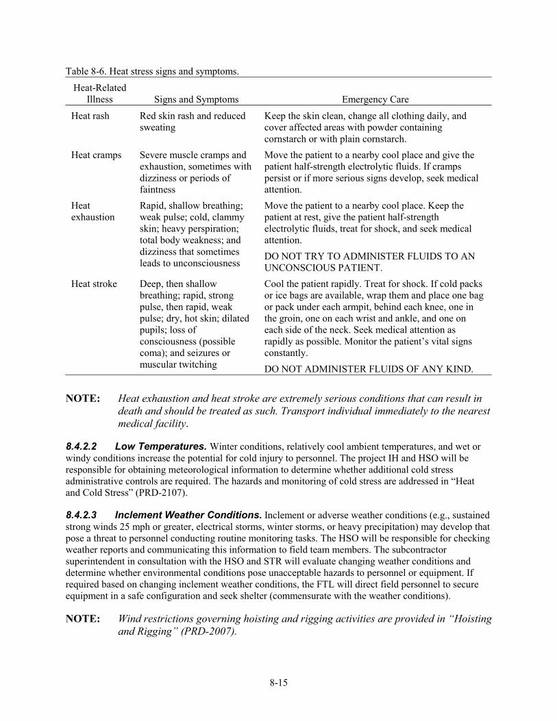
8-15
Table 8-6. Heat stress signs and symptoms.
Heat-Related Illness Signs and Symptoms Emergency Care
Heat rash Red skin rash and reduced sweating
Keep the skin clean, change all clothing daily, and cover affected areas with powder containing cornstarch or with plain cornstarch.
Heat cramps Severe muscle cramps and exhaustion, sometimes with dizziness or periods of faintness
Move the patient to a nearby cool place and give the patient half-strength electrolytic fluids. If cramps persist or if more serious signs develop, seek medical attention.
Heat exhaustion
Rapid, shallow breathing; weak pulse; cold, clammy skin; heavy perspiration; total body weakness; and dizziness that sometimes leads to unconsciousness
Move the patient to a nearby cool place. Keep the patient at rest, give the patient half-strength electrolytic fluids, treat for shock, and seek medical attention. DO NOT TRY TO ADMINISTER FLUIDS TO AN UNCONSCIOUS PATIENT.
Heat stroke Deep, then shallow breathing; rapid, strong pulse, then rapid, weak pulse; dry, hot skin; dilated pupils; loss of consciousness (possible coma); and seizures or muscular twitching
Cool the patient rapidly. Treat for shock. If cold packs or ice bags are available, wrap them and place one bag or pack under each armpit, behind each knee, one in the groin, one on each wrist and ankle, and one on each side of the neck. Seek medical attention as rapidly as possible. Monitor the patient’s vital signs constantly. DO NOT ADMINISTER FLUIDS OF ANY KIND.
NOTE: Heat exhaustion and heat stroke are extremely serious conditions that can result in
death and should be treated as such. Transport individual immediately to the nearest medical facility.
8.4.2.2 Low Temperatures. Winter conditions, relatively cool ambient temperatures, and wet or windy conditions increase the potential for cold injury to personnel. The project IH and HSO will be responsible for obtaining meteorological information to determine whether additional cold stress administrative controls are required. The hazards and monitoring of cold stress are addressed in “Heat and Cold Stress” (PRD-2107).
8.4.2.3 Inclement Weather Conditions. Inclement or adverse weather conditions (e.g., sustained strong winds 25 mph or greater, electrical storms, winter storms, or heavy precipitation) may develop that pose a threat to personnel conducting routine monitoring tasks. The HSO will be responsible for checking weather reports and communicating this information to field team members. The subcontractor superintendent in consultation with the HSO and STR will evaluate changing weather conditions and determine whether environmental conditions pose unacceptable hazards to personnel or equipment. If required based on changing inclement weather conditions, the FTL will direct field personnel to secure equipment in a safe configuration and seek shelter (commensurate with the weather conditions).
NOTE: Wind restrictions governing hoisting and rigging activities are provided in “Hoisting and Rigging” (PRD-2007).
8-16
8.4.2.4 Noise. Personnel working at the task site may be exposed to noise levels that exceed 85 decibel A-weighted for an 8-hour time-weighted average and 83 decibel A-weighted for a 10-hour time-weighted average from various pieces of equipment in use. The HSO will implement the requirements of “Hearing Conservation” (PRD-2108), including establishing noise areas around or near noise-generating equipment as necessary based on new or existing documented monitoring data.
8.4.2.5 Biological Hazards. Hantavirus may be present in the nesting and fecal matter of deer mice. A potential exists for project personnel to disturb nesting or fecal matter during the course of mobilization and intrusive activities and from material-handling tasks. If such materials are disturbed, they can become airborne and create a potential inhalation pathway for the virus. Also, contact and improper removal of these materials may provide additional inhalation exposure risks.
If suspect rodent nesting or excrement material is encountered, the HSO will be notified immediately, and no attempt will be made to remove or clean the area. Following an evaluation of the area, the HSO in consultation with the IH will provide the necessary guidance for protective equipment, mixing, and application of the disinfecting solution and the proper waste disposal method (see PRD-2102).
Snakes, spiders, ticks, mosquitoes, and insects also may be encountered in the SDA. Common areas of risk include material stacking and staging areas, under existing structures (e.g., well surface completion cement pads), under boxes, and other areas that provide shelter for snakes and spiders. Protective clothing will prevent insects from direct contact with personnel; however, repellant may be required during Level D activities.
8.4.2.6 Walking and Working Surfaces. Slip, trip, and fall hazards exist from uneven terrain, protruding rocks, holes, well surface completion configurations, existing SDA probes, work site equipment or lines, wet or muddy environmental conditions, and snow- or ice-covered walking surfaces. Slippery or uneven surfaces increase the likelihood of back injuries, overexertion injuries, slips, and falls. Where identified or anticipated, personnel will be made aware of existing tripping hazards during the prejob briefing, and mitigation steps will be taken to eliminate or minimize slip hazards. Snow- or ice-covered walking surfaces will be cleared or a combination of sand and salt applied. Additionally, personnel will wear appropriate footwear for the anticipated conditions.
8.4.2.7 Excavation, Surface Penetrations, and Outages. Surface penetrations and excavations will be required during grout injection and grout containment unit installation. All excavations and surface penetrations will be conducted in compliance with the requirements of “Excavations and Surface Penetrations” (PRD-2014; PRD-22). Underground utilities will be identified through the use of a subsurface investigation. An outage request will be submitted by the subcontractor and coordinated through the STR for any utilities, roads, or other services that may be affected during execution of the project, including but not limited to work near overhead power lines.
8.4.2.8 Confined Spaces. No confined spaces have been identified or are anticipated during grouting tasks. If a suspected confined space is encountered and not properly posted, it will be treated as a permit-required confined space until a determination is made by the project safety or IH professional. Work in confined spaces will be conducted in accordance with “Confined Spaces” (PRD-2110).
8.4.2.9 Elevated Work. Personnel working on a surface with exposed fall hazards greater than 6 ft will be protected using barricades, fall restraint, or fall arrest as required in “Fall Protection” (PRD-2002). Personnel working or utilizing ladders will follow the requirements of “Ladders” (PRD-2003). All scaffold erection and work will be conducted in accordance with “Scaffolding” (PRD-2004). The use of
8-17
aerial lifts will be performed in accordance with the requirements in “Aerial Lifts and Elevating Work Platforms” (PRD-2006).
8.4.2.10 Hazard Communications. The subcontractor will implement a hazard communication program that meets the requirements of “Hazard Communication” (PRD-2101). All subcontractor employees will be trained to the program, and all personnel working at the project site will be informed of the program and understand where and how to access information such as MSDSs.
8.5 Other Site Hazards and Inspections
Task-site personnel should continually be alert for potential hazards and immediately inform the STR or HSO so corrective actions can be taken to eliminate or mitigate the hazard. All personnel have stop work authority as described in “Stop Work Authority” (PRD-1004) and have the responsibility to exercise this authority if unsafe conditions are identified that pose an immediate risk to personnel or equipment. The HSO will visually inspect the site to ensure that barriers and signs are being maintained, unsafe conditions are corrected, and debris is not accumulating on the site. These inspections will be conducted in addition to regulatory mandated inspections (as applicable).

8-18
9-1
9. PERSONAL PROTECTIVE EQUIPMENT
Anyone entering the work control area must be protected against safety and contaminant exposure hazards. The purpose of PPE is to shield or isolate personnel from chemical, safety, and physical hazards that are not eliminated through engineering or other controls. It is important to realize that no PPE ensemble can protect against all hazards under all conditions and that work practices and adequate training will enhance the level and effectiveness of protection to workers. All personnel will complete PPE training before donning and using PPE. This training will be documented by the employer and available at the project site. All use, storage, and maintenance related to PPE will comply with the requirements of “Personal Protective Equipment” (PRD-2001).
All personnel required to wear respirators will complete training and be fit-tested before being assigned a respirator in accordance with the training and documentation requirements of Section 4 of this HASP. Requirements for respirator use (i.e., emergency use, storage, cleaning, and maintenance), as stated in “Respiratory Protection” (PRD-2109; MCP-2726), will be followed as appropriate.
9.1 Project-Specific Personal Protective Equipment Requirements
The minimum level of PPE for work performed inside the work control area at the early actions beryllium project work site will be Level D. The minimum Level D PPE requirements will include the following:
• Hard hat
• Safety glasses with side shields
• Safety toe, above-the-ankle boots
• Standard work clothing, including over-the-shoulder shirt and full-length pants
• Leather gloves or equivalent for material-handling tasks.
Optional Level D modifications will be implemented as determined by the HSO with IH, safety engineer, and RCT concurrence, as appropriate. These modifications may include:
• Chemical-resistant or anticontamination clothing
• Chemical-resistant or anticontamination hand and foot protection
• Specialized protective equipment (e.g., hearing protection, face shields, welding goggles, chemical splash goggles, aprons, and lab coats).
The HSO with concurrence from the IH, safety engineer, and RCT will upgrade to Level C or Level B PPE, including the use of air-purifying or air-supplied respiratory protection based on actual tasks being performed, field conditions or observations, air monitoring or sampling results, and subcontractor equipment engineering control design and work practices.
9-2
9.2 Personal Protective Equipment Levels
The four levels of PPE (e.g., Level A, B, C, and D) for HAZWOPER tasks are defined in HAZWOPER (29 CFR 1910.120, Appendix B). The HSO will continuously evaluate the actual field conditions to determine adequacy of the PPE protection levels.
9.3 Protective Clothing Upgrading and Downgrading
The HSO in consultation with the project IH and safety professional will be responsible for determining when to upgrade or downgrade PPE requirements. Upgrading or downgrading of PPE requirements based on current conditions is a normal occurrence and is routinely employed during HAZWOPER activities to maximize efficiency and to meet site-specific conditions without compromising personnel safety and health. If changing conditions are encountered, new work control documents (e.g., SWP, JSA, and RWP) may need to be updated to reflect these changes.
9.4 Inspection of Personal Protective Equipment
All PPE ensemble components must be inspected before use and when in use. Once PPE is donned, self-inspection and the use of the buddy system will serve as the principal forms of inspection. If at any time PPE should become damaged or unserviceable, an individual will inform others of the problem and proceed directly to the controlled work-area exit point to doff and replace the equipment. Additionally, all PPE that becomes grossly contaminated with grout will be cleaned or replaced.
10-1
10. DECONTAMINATION PROCEDURES
If contact with potentially contaminated surfaces or materials cannot be avoided, then additional engineering controls in combination with PPE upgrades may be necessary to control the contact hazard. However, if chemical or radiological contamination is encountered at levels requiring decontamination, this section provides guidance on how it will be conducted.
10.1 Contamination Control and Prevention
Contamination control and prevention processes will be implemented to minimize personnel contact with potentially contaminated surfaces if such surfaces are encountered and contacted during grouting activities. The following contamination control and prevention measures will be employed if contamination is encountered:
• Identification of potential sources of contamination; design containment, isolation, and engineering controls to eliminate or mitigate any potential for contact or release of contaminants
• Limitation of the number of personnel, equipment, and materials that enter the contaminated area
• Implementation of immediate decontamination procedures to prevent the spread of contamination (if contamination is found on the outer surfaces of equipment)
• Utilization of only the established control entry and exit point from the contaminated area to minimize the potential for cross-contamination and expedite contamination control surveys
• Wearing of disposable outer garments and utilization of disposable equipment (where possible)
• Using hold points within procedures and work orders to monitor for contamination where anticipated.
10.2 Equipment and Personnel Decontamination
Decontamination procedures for personnel and equipment are not anticipated to be required beyond normal PPE changeout and technical procedures for cleaning sampling equipment.
10.2.1 Equipment Decontamination
If radionuclide decontamination operations are required for equipment or areas, they will be performed under the direction of RadCon in accordance with the “Radiological Control Manual” (PRD-183). Nonradioactive decontamination will be evaluated on a case-by-case basis by the HSO with concurrence of the project IH and environmental support to determine the most appropriate decontamination methods and to designate the required PPE.
10-2
10.2.2 Personnel Decontamination
Engineering controls, in conjunction with work controls, PPE, and proper handling of potentially contaminated equipment, will serve as the primary means to eliminate the need for personnel decontamination. If personnel radionuclide decontamination operations are required, it will be performed under the direction of the RCT in accordance with “Personnel Decontamination” (MCP-148). If nonradiological decontamination is required, the HSO with concurrence of the IH and safety professional will determine the safest and most appropriate decontamination method, generally involving soap and warm water. If the contamination poses a potential health risk, then the contaminated person will be evaluated by medical personnel as soon as possible following the exposure.
11-1
11. EMERGENCY RESPONSE PLAN
This section defines the responsibilities for the project and the INEEL emergency response organization (ERO) by providing guidance for responding to abnormal events during project activity.
This emergency response plan addresses OSHA emergency response activities as defined by HAZWOPER (29 CFR 1910.120; 29 CFR 1926.65) and DOE emergencies as defined by “Comprehensive Emergency Management System” (DOE O 151.1B) and “Environment, Safety, and Health Reporting” (DOE O 231.1A). This response plan is implemented in concert with “INEEL Emergency Plan Resource Conservation and Recovery Act (RCRA) Contingency Plan” (PLN-114).
The “INEEL Emergency Plan Resource Conservation and Recovery Act (RCRA) Contingency Plan” (PLN-114) may be activated in response to events occurring at the RWMC or at the INEEL or may be activated at the discretion of the emergency coordinator or emergency action manager. Once the INEEL plan is activated, project personnel will follow the direction and guidance communicated by the emergency coordinator.
NOTE: The OSHA term emergency is not defined the same as an emergency as classified by “Comprehensive Emergency Management System” (DOE O 151.1B) and “Environment, Safety, and Health Reporting” (DOE O 231.1A). For this reason, the term event will be used in this section when referring to project HAZWOPER emergencies.
Emergency response plans must be developed and put into place before any project activity begins. Preplanning makes it possible for the project to anticipate and appropriately respond to abnormal events that can affect project activity. Preplanning also ensures that the project emergency response program is integrated with that of the INEEL and RWMC.
All emergencies will be reported through the RWMC shift supervisor to the ERO for classification in accordance with Section 4 of “INEEL Emergency Plan Resource Conservation and Recovery Act (RCRA) Contingency Plan” (PLN-114). If the RWMC ERO is activated, site emergency response will follow “Emergency Management Addendum 3—RWMC” (PLN-114-3).
On-scene response to and mitigation of site emergencies could require the expertise of both INEEL personnel and INEEL fire department personnel. Emergencies that could occur include:
• Accidents resulting in injury
• Fires
• Spills of hazardous or radiological materials
• Tornadoes, earthquakes, and other adverse natural phenomena
• Vehicle or transportation emergencies
• Safeguard and security emergencies
• Emergencies at nearby facilities that could prompt evacuation or take-cover actions at the task site.
11-2
11.1 Types of Emergency Events
11.1.1 Events Requiring Emergency Notifications
Certain events require courtesy notifications but do not require a response from the INEEL ERO. In these cases, the project STR or designee will immediately notify the RWMC shift supervisor or Warning Communications Center (WCC) if the shift supervisor cannot be contacted. Notification by the STR or designee should describe the event and state that no emergency response support is required. Examples of these types of events include but are not limited to the following:
• Personal injury at the site requiring medical evaluation or first-aid treatment but not requiring an ambulance response
• Equipment or vehicle accident that results in damage to the vehicle or property ONLY
• Small fire that is immediately extinguished with a hand-held fire extinguisher (also requires notification to the INEEL fire department)
• Any other event deemed potentially reportable.
11.1.2 Events Requiring Local Project Evacuation or Idaho National Engineering and Environmental Laboratory Emergency Response Organization Response
Some events that could occur at the project site or at the RWMC may require support from the INEEL ERO or may require a local area evacuation of the project. In these cases, the project STR will immediately notify the RWMC shift supervisor. If the shift supervisor cannot be contacted immediately, then the WCC will be contacted. Notification of the FTL will describe the event and will request emergency response resources as appropriate. After being informed of the event, the RWMC emergency coordinator may elect to activate the command post. Once the command post is operational, all emergency response activities will be coordinated through the emergency coordinator. The specific actions to be taken in response to emergency alarms are described in Section 11.3. Examples of these types of events include but are not limited to those listed below:
• Fire that is burning beyond an incipient stage and cannot be extinguished with hand-held extinguishers
• Large spill at the project that cannot be immediately contained or controlled
• Serious injury to a worker or workers.
A positive sweep of the site being worked will be done by the HSO and STR before evacuating the site for accountability purposes.
NOTE: When the project site has been evacuated, the STR will serve as the project area warden and ensure the RWMC shift supervisor or emergency coordinator (if command post is formed) that notification has been made that project personnel have been evacuated and accounted for.
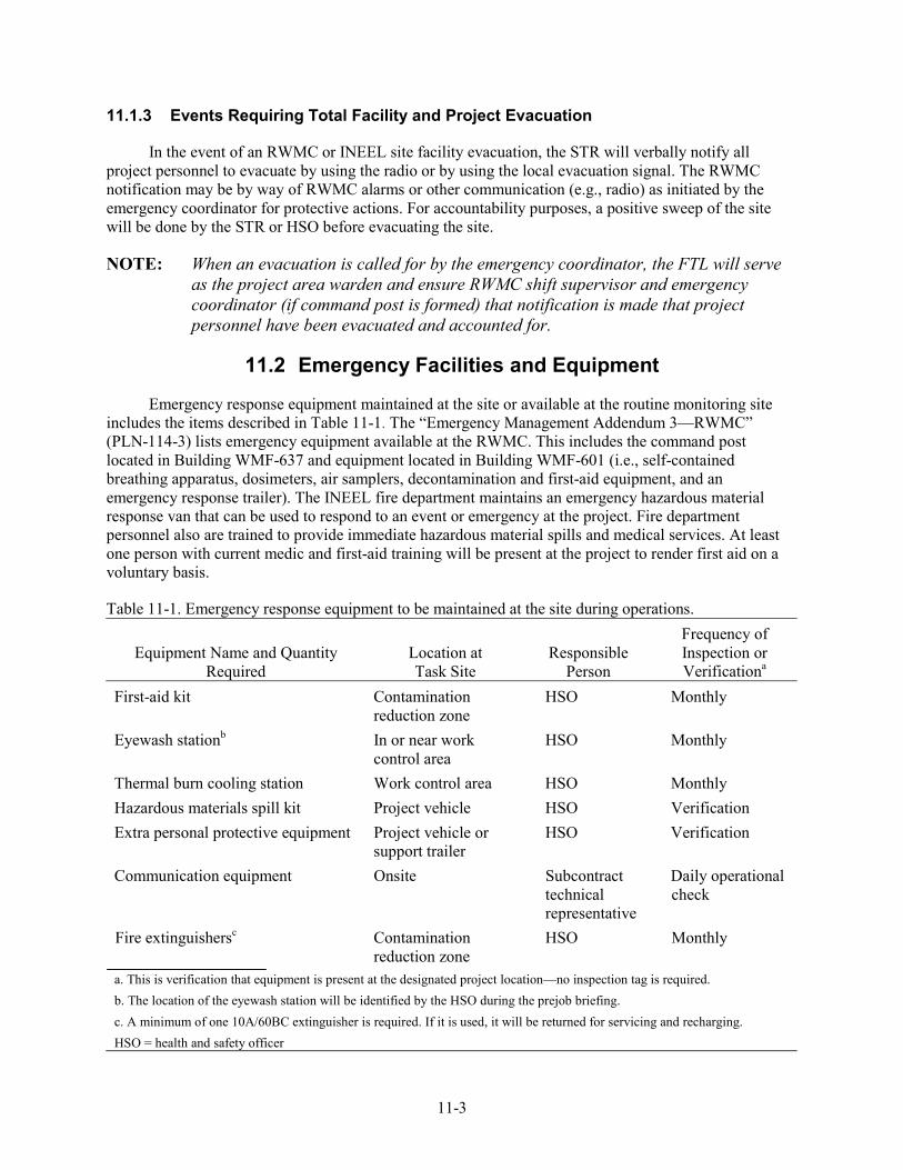
11-3
11.1.3 Events Requiring Total Facility and Project Evacuation
In the event of an RWMC or INEEL site facility evacuation, the STR will verbally notify all project personnel to evacuate by using the radio or by using the local evacuation signal. The RWMC notification may be by way of RWMC alarms or other communication (e.g., radio) as initiated by the emergency coordinator for protective actions. For accountability purposes, a positive sweep of the site will be done by the STR or HSO before evacuating the site.
NOTE: When an evacuation is called for by the emergency coordinator, the FTL will serve as the project area warden and ensure RWMC shift supervisor and emergency coordinator (if command post is formed) that notification is made that project personnel have been evacuated and accounted for.
11.2 Emergency Facilities and Equipment
Emergency response equipment maintained at the site or available at the routine monitoring site includes the items described in Table 11-1. The “Emergency Management Addendum 3—RWMC” (PLN-114-3) lists emergency equipment available at the RWMC. This includes the command post located in Building WMF-637 and equipment located in Building WMF-601 (i.e., self-contained breathing apparatus, dosimeters, air samplers, decontamination and first-aid equipment, and an emergency response trailer). The INEEL fire department maintains an emergency hazardous material response van that can be used to respond to an event or emergency at the project. Fire department personnel also are trained to provide immediate hazardous material spills and medical services. At least one person with current medic and first-aid training will be present at the project to render first aid on a voluntary basis.
Table 11-1. Emergency response equipment to be maintained at the site during operations.
Equipment Name and Quantity Required
Location at Task Site
Responsible Person
Frequency of Inspection or Verificationa
First-aid kit Contamination reduction zone
HSO Monthly
Eyewash stationb In or near work control area
HSO Monthly
Thermal burn cooling station Work control area HSO Monthly Hazardous materials spill kit Project vehicle HSO Verification Extra personal protective equipment Project vehicle or
support trailer HSO Verification
Communication equipment Onsite Subcontract technical representative
Daily operational check
Fire extinguishersc Contamination reduction zone
HSO Monthly
a. This is verification that equipment is present at the designated project location—no inspection tag is required. b. The location of the eyewash station will be identified by the HSO during the prejob briefing. c. A minimum of one 10A/60BC extinguisher is required. If it is used, it will be returned for servicing and recharging. HSO = health and safety officer
11-4
11.3 Emergency Communications
In the event of an emergency, the capability to summon INEEL emergency response resources to immediately notify site personnel and inform others of site emergencies is required. Communications equipment at the task site will be a combination of radios, telephones (e.g., mobile, cellular, or facility), and pagers. Communication methods described below will be used during emergency situations.
During emergency situations, the RWMC shift supervisor will be notified of any project emergency event. The RWMC shift supervisor will then make the required RWMC emergency coordinator notification. The following information should be communicated, as available, to the shift supervisor:
NOTE: If the RWMC shift supervisor cannot be contacted, then the WCC will be notified of the event and the information listed below communicated. The WCC also must be told that RWMC notification to the RWMC shift supervisor and emergency coordinator has not been made.
• The caller’s name, title (e.g., STR or HSO), telephone number, and pager number
• Exact location of the emergency
• Nature of the emergency including time of occurrence, current site conditions, and special hazards in the area
• Injuries, if any, including numbers of injured, types of injuries, and conditions of injured
• Emergency response resources required (e.g., fire, hazardous material, and ambulance)
• Additional information as requested.
11.4 Emergency Recognition and Prevention
All project personnel should be constantly alert for potential hazardous situations and signs and symptoms of chemical exposure or releases. All project personnel will be trained in proper site access and egress procedures in response to project events and INEEL emergencies as part of the project-specific training HASP. Visitors also will receive this training on a graded approach based on their access requirement. Alarm identification, location and use of communication equipment, location and use of site emergency equipment, and evacuation routes will be covered. Emergency phone numbers and evacuation route maps will be located in the project trailer. All field personnel should be familiar with the techniques for hazard recognition and assigned action levels.
11.5 Emergency Response Roles and Responsibilities
11.5.1 The Idaho National Engineering and Environmental Laboratory and Radioactive Waste Management Complex Emergency Response Organization
The INEEL ERO and RWMC ERO structures are based on the incident command system and are described in “INEEL Emergency Plan Resource Conservation and Recovery Act (RCRA) Contingency Plan” (PLN-114) and “Emergency Management Addendum 3—RWMC” (PLN-114-3).
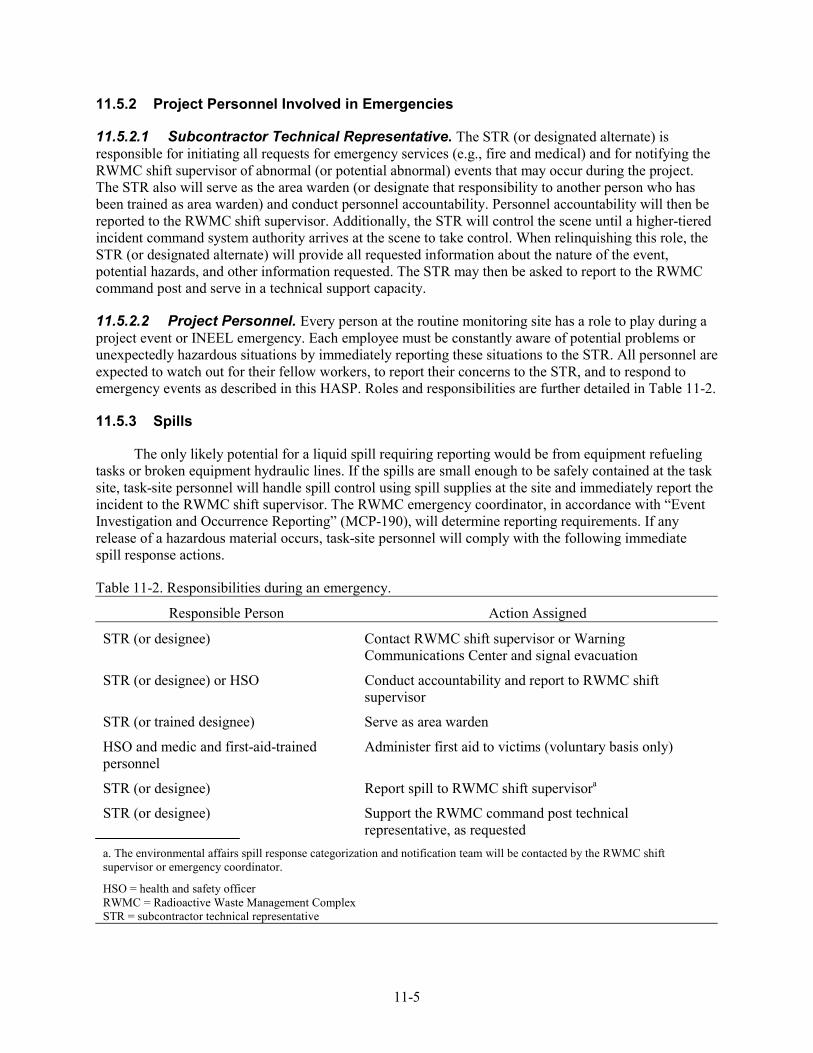
11-5
11.5.2 Project Personnel Involved in Emergencies
11.5.2.1 Subcontractor Technical Representative. The STR (or designated alternate) is responsible for initiating all requests for emergency services (e.g., fire and medical) and for notifying the RWMC shift supervisor of abnormal (or potential abnormal) events that may occur during the project. The STR also will serve as the area warden (or designate that responsibility to another person who has been trained as area warden) and conduct personnel accountability. Personnel accountability will then be reported to the RWMC shift supervisor. Additionally, the STR will control the scene until a higher-tiered incident command system authority arrives at the scene to take control. When relinquishing this role, the STR (or designated alternate) will provide all requested information about the nature of the event, potential hazards, and other information requested. The STR may then be asked to report to the RWMC command post and serve in a technical support capacity.
11.5.2.2 Project Personnel. Every person at the routine monitoring site has a role to play during a project event or INEEL emergency. Each employee must be constantly aware of potential problems or unexpectedly hazardous situations by immediately reporting these situations to the STR. All personnel are expected to watch out for their fellow workers, to report their concerns to the STR, and to respond to emergency events as described in this HASP. Roles and responsibilities are further detailed in Table 11-2.
11.5.3 Spills
The only likely potential for a liquid spill requiring reporting would be from equipment refueling tasks or broken equipment hydraulic lines. If the spills are small enough to be safely contained at the task site, task-site personnel will handle spill control using spill supplies at the site and immediately report the incident to the RWMC shift supervisor. The RWMC emergency coordinator, in accordance with “Event Investigation and Occurrence Reporting” (MCP-190), will determine reporting requirements. If any release of a hazardous material occurs, task-site personnel will comply with the following immediate spill response actions.
Table 11-2. Responsibilities during an emergency.
Responsible Person Action Assigned
STR (or designee) Contact RWMC shift supervisor or Warning Communications Center and signal evacuation
STR (or designee) or HSO Conduct accountability and report to RWMC shift supervisor
STR (or trained designee) Serve as area warden
HSO and medic and first-aid-trained personnel
Administer first aid to victims (voluntary basis only)
STR (or designee) Report spill to RWMC shift supervisora
STR (or designee) Support the RWMC command post technical representative, as requested
a. The environmental affairs spill response categorization and notification team will be contacted by the RWMC shift supervisor or emergency coordinator.
HSO = health and safety officer RWMC = Radioactive Waste Management Complex STR = subcontractor technical representative
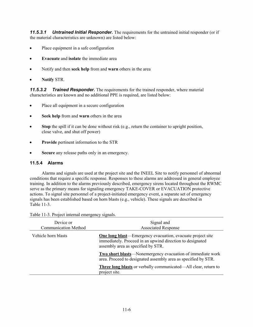
11-6
11.5.3.1 Untrained Initial Responder. The requirements for the untrained initial responder (or if the material characteristics are unknown) are listed below:
• Place equipment in a safe configuration
• Evacuate and isolate the immediate area
• Notify and then seek help from and warn others in the area
• Notify STR.
11.5.3.2 Trained Responder. The requirements for the trained responder, where material characteristics are known and no additional PPE is required, are listed below:
• Place all equipment in a secure configuration
• Seek help from and warn others in the area
• Stop the spill if it can be done without risk (e.g., return the container to upright position, close valve, and shut off power)
• Provide pertinent information to the STR
• Secure any release paths only in an emergency.
11.5.4 Alarms
Alarms and signals are used at the project site and the INEEL Site to notify personnel of abnormal conditions that require a specific response. Responses to these alarms are addressed in general employee training. In addition to the alarms previously described, emergency sirens located throughout the RWMC serve as the primary means for signaling emergency TAKE-COVER or EVACUATION protective actions. To signal site personnel of a project-initiated emergency event, a separate set of emergency signals has been established based on horn blasts (e.g., vehicle). These signals are described in Table 11-3.
Table 11-3. Project internal emergency signals.
Device or Communication Method
Signal and Associated Response
Vehicle horn blasts One long blast—Emergency evacuation, evacuate project site immediately. Proceed in an upwind direction to designated assembly area as specified by STR.
Two short blasts—Nonemergency evacuation of immediate work area. Proceed to designated assembly area as specified by STR.
Three long blasts or verbally communicated—All clear, return to project site.
11-7
11.5.4.1 Take CoverContinuous Siren. Radiation or hazardous material releases, weather conditions, or other event or emergency conditions may require that all personnel take cover indoors in the nearest building. A TAKE-COVER protective action may be initiated as part of a broader response to an emergency situation and may precede an evacuation order. The order to TAKE COVER is usually announced by activating the RWMC emergency siren. The signal to take cover is a CONTINUOUS SIREN that can be heard throughout the RWMC area. Remember, STEADY = STAY. However, the order to take cover can also be given by word of mouth, radio, or voice paging system. When ordered to TAKE COVER, project personnel will place the site in a safe condition (as appropriate) and then seek shelter in the project trailer or vehicle (if outside the RWMC facility). Eating, drinking, and smoking are not permitted during take-cover conditions.
11.5.4.2 Total Area EvacuationAlternating Siren. A total area evacuation is the complete withdrawal of personnel from the project site and the entire RWMC area. The evacuation signal is an ALTERNATING SIREN that can be heard throughout the SDA. Remember, ALTERNATE = EVACUATE. A single long blast of the vehicle horn serves as the project’s alternate emergency evacuation alarm. However, the order to evacuate also can be given by word of mouth, radio, or voice paging system. When ordered to EVACUATE, project personnel will place the site in a safe condition (as appropriate) and then proceed along the specified evacuation route to the designated assembly area or as directed by the emergency coordinator.
For total area evacuations, the RWMC command post is activated, and all personnel will gather at the primary RWMC evacuation assembly area or the location designated by the emergency coordinator. The FTL or trained alternate will then complete the personnel accountability using the attendance log. In this situation, the project area warden reports the result of the accountability process to the RWMC emergency coordinator.
11.5.4.3 Local Area EvacuationVehicle Horn Blast. A local area evacuation is the complete withdrawal of personnel from the project site, but it does not require the complete evacuation of the entire RWMC or INEEL area. A single long horn blast (vehicle) will serve as the project’s primary emergency evacuation signal (as listed on Table 11-3). However, the order to evacuate also can be given by word of mouth, radio, or voice paging system. When ordered to evacuate the project site, personnel will place the site in a safe condition (as appropriate) and then proceed along the specified evacuation route to the assembly area designated for local area evacuations or as directed by the FTL. Eating, drinking, and smoking are not permitted during emergency evacuations.
11.5.5 Personnel Accountability and Area Warden
Project personnel are required to evacuate the site in response to TAKE COVER, EVACUATION, and local evacuation alarms. In each case, the STR (or trained designee) will account for the people present on the site at the time the alarm was initiated. The STR (or trained alternate) serves as the area warden for the project and completes the personnel accountability (following positive sweeps of the project site) based on the attendance log. The results of this accountability will then be communicated to the STR for reporting to the RWMC shift supervisor or emergency coordinator (if the command post has been formed).
11.5.6 Notifications
As directed by the office of the U.S. Secretary of Energy, the RWMC operations director is responsible for immediately notifying the DOE and local off-Site agencies of all significant abnormal events that occur at the RWMC. This duty is in addition to the notification requirements established in INEEL procedures for events that are categorized as emergencies or unusual occurrences. For this reason,
11-8
the project will immediately report all abnormal events that occur on the project site to the RWMC shift supervisor and to the WCC. The WCC will in turn notify the appropriate INEEL emergency response resources and other INEEL facilities as appropriate. The RWMC shift supervisor and the WCC share the responsibility for notifying the RWMC facility manager, emergency coordinator, and area director (as appropriate). Normally the STR is responsible for making the event notifications described above. Additional project notification may be made by the STR. The emergency coordinator is the single POC between the project and the INEEL ERO and off-Site personnel or agencies. The emergency coordinator will make all off-Site notifications and respond to all media requests.
11.5.7 Evacuation Assembly Areas and Central Facilities Area Medical Facility
The RWMC maintains primary and secondary evacuation assembly areas (see Figure 11-1). These routes may be used in response to a total RWMC area evacuation as directed by the emergency coordinator. Copies of the evacuation assembly areas and the CFA-1612 medical facility route (see Figure 11-2) will be posted at the project site in the project administrative trailer.
11.6 Reentry and Recovery
11.6.1 Reentry
During an emergency response, it is sometimes necessary to reenter the scene of the event. Reasons for performing a reentry may include:
• Personnel search and rescues
• Medical first-aid responses
• Safe shutdown actions
• Mitigating actions
• Evaluating and preparing damage reports
• Radiation or hazardous material surveys.
Reentries will be carefully planned to ensure that personnel are protected from harm and to prevent initiating another emergency event. Reentry planning is undertaken as a graded approach depending on the nature of the initiating event.
11.6.2 Recovery
After the initial corrective actions have been taken and effective control established, response efforts will shift toward recovery. Recovery is the process of assessing postevent and postemergency conditions and developing a plan for returning to preevent and preemergency conditions, when possible, and following the plan to completion. The emergency coordinator and emergency action manager are responsible for determining when an emergency situation is sufficiently stable to terminate the emergency and enter the recovery phase. The project manager, with concurrence from the RWMC site area director, will appoint the recovery manager.
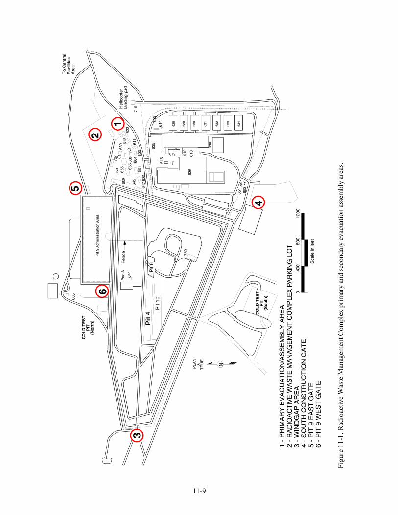
11-9
Figu
re 1
1-1.
Rad
ioac
tive
Was
te M
anag
emen
t Com
plex
prim
ary
and
seco
ndar
y ev
acua
tion
asse
mbl
y ar
eas.
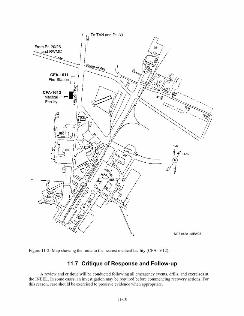
11-10
Figure 11-2. Map showing the route to the nearest medical facility (CFA-1612).
11.7 Critique of Response and Follow-up
A review and critique will be conducted following all emergency events, drills, and exercises at the INEEL. In some cases, an investigation may be required before commencing recovery actions. For this reason, care should be exercised to preserve evidence when appropriate.
11-11
11.8 Telephone and Radio Contact Reference List
A list of the POCs for the project will be provided to the RWMC shift supervisor. This list will include, as a minimum, the names and telephone numbers for the following personnel:
• Project manager
• Project engineer
• RWMC construction supervisor
• RWMC construction STR
• Construction management safety engineer
• RWMC safety engineer
• Construction IH
• RWMC IH
• RWMC ES&H manager
• RWMC RadCon manager
• RWMC RadCon engineer
• Subcontractor superintendent
• Subcontractor HSO.

11-12
12-1
12. REFERENCES
29 CFR 1910, 2004, “Occupational Safety and Health Standards,” Code of Federal Regulations, Office of the Federal Register.
29 CFR 1926, 2002, “Safety and Health Regulations for Construction,” Code of Federal Regulations, Office of the Federal Register.
42 USC § 9601 et seq., 1980, “Comprehensive Environmental Response, Compensation and Liability Act of 1980 (CERCLA/Superfund),” United States Code.
ACGIH, 2001, Threshold Limit Values Booklet, American Conference of Government Industrial Hygienists.
Becker, B. H., J. D. Burgess, K. J. Holdren, D. K. Jorgensen, S. O. Magnuson, and A. J. Sondrup, 1998, Interim Risk Assessment and Contaminant Screening for the Waste Area Group 7 Remedial Investigation, DOE/ID-10569, U.S. Department of Energy Idaho Operations Office.
DOE O 151.1B, 2003, “Comprehensive Emergency Management System,” U.S. Department of Energy.
DOE O 231.1A, 2003, “Environment, Safety, and Health Reporting,” U.S. Department of Energy.
HAD-268, 2004, “Hazard Assessment for Beryllium Block Grouting at the Radioactive Waste Management Complex,” Rev. 0, Idaho Completion Project.
Manual 14A, 2004, Manual 14A—Safety and Health—Occupation Safety and Fire Protection, TOC-48, Rev. 140, Idaho National Engineering and Environmental Laboratory.
Manual 14B, 2004, Manual 14B—Safety and Health—Occupational Medical and Industrial Hygiene, TOC-49, Rev. 79, Idaho National Engineering and Environmental Laboratory.
Manual 15B, 2004, Manual 15B—Radiation Protection Procedures, TOC-5, Rev. 125, Idaho National Engineering and Environmental Laboratory.
MCP-7, 2004, “Radiological Work Permit,” Rev. 19, Idaho National Engineering and Environmental Laboratory.
MCP-50, 2002, “Chronic Beryllium Disease Prevention,” Rev. 3, Manual 14B—Safety and Health—Occupational Medical and Industrial Hygiene, Idaho National Engineering and Environmental Laboratory.
MCP-148, 2000, “Personnel Decontamination,” Rev. 4, Manual 15C—Radiological Control Procedures, Idaho National Engineering and Environmental Laboratory.
MCP-153, 2002, “Industrial Hygiene Exposure Assessment,” Rev. 6, Manual 14B—Safety and Health—Occupational Medical and Industrial Hygiene, Idaho National Engineering and Environmental Laboratory.
MCP-187, 2002, “Posting Radiological Control Areas,” Rev. 9, Idaho National Engineering and Environmental Laboratory.
12-2
MCP-190, 2003, “Event Investigation and Occurrence Reporting,” Rev. 10, Manual 9—Operations, Idaho National Engineering and Environmental Laboratory.
MCP-357, 2003, “Job-Specific Air Sampling/Monitoring,” Rev. 11, Idaho National Engineering and Environmental Laboratory.
MCP-2726, 2003, “Respiratory Protection,” Rev. 9, Manual 14B—Safety and Health—Occupational Medical and Industrial Hygiene, Idaho National Engineering and Environmental Laboratory.
MCP-2748, 1997, “Hazardous Waste Operations and Emergency Response,” Rev. 1, Manual 14B—Safety and Health—Occupational Medical and Industrial Hygiene, Idaho National Engineering and Environmental Laboratory.
MCP-3003, 2003, “Performing Pre-Job Briefings and Documenting Feedback,” Rev. 11, Idaho National Engineering and Environmental Laboratory.
NIOSH, 1985, Occupational Safety and Health Guidance Manual for Hazardous Waste Site Activities, National Institute of Occupational Safety and Health, Occupational Safety and Health Administration, United States Coast Guard, and U.S. Environmental Protection Agency, DHHS (NIOSH) Publication No. 85-115.
PDD-1005, 2004, “INEEL Line Management and Operations Manual,” Rev. 7, Idaho National Engineering and Environmental Laboratory.
PLN-114, 2003, “INEEL Emergency Plan Resource Conservation and Recovery Act (RCRA) Contingency Plan,” Rev. 20, Idaho National Engineering and Environmental Laboratory.
PLN-114-3, 2004, “Emergency Management Addendum 3—RWMC,” Rev. 63, Idaho National Engineering and Environmental Laboratory.
PRD-22, 2004, “Excavation and Surface Penetration,” Rev. 4, Companywide Manual 14A—Safety and Health—Occupational Safety and Fire Protection, Idaho National Engineering and Environmental Laboratory.
PRD-183, 2004, “Radiological Control Manual,” Rev. 7, Manual 15A—Radiation Protection—INEEL Radiological Control, Idaho National Engineering and Environmental Laboratory.
PRD-320, 2004, “Pressure System Safety,” Rev. 0, Companywide Manual 14A—Safety and Health—Occupational Safety and Fire Protection, Idaho National Engineering and Environmental Laboratory.
PRD-1004, 1997, “Stop Work Authority,” Rev. 0, Subcontractor Requirements Manual, Idaho National Engineering and Environmental Laboratory.
PRD-2001, 2001, “Personal Protective Equipment,” Rev. 3, Subcontractor Requirements Manual, Idaho National Engineering and Environmental Laboratory.
PRD-2002, 2001, “Fall Protection,” Rev. 3, Subcontractor Requirements Manual, Idaho National Engineering and Environmental Laboratory.
12-3
PRD-2003, 2004, “Ladders,” Rev. 1, Subcontractor Requirements Manual, Idaho National Engineering and Environmental Laboratory.
PRD-2004, 2004, “Scaffolding,” Rev. 3, Subcontractor Requirements Manual, Idaho National Engineering and Environmental Laboratory.
PRD-2006, 2001, “Aerial Lifts and Elevating Work Platforms,” Rev. 1, Subcontractor Requirements Manual, Idaho National Engineering and Environmental Laboratory.
PRD-2007, 2003, “Hoisting and Rigging,” Rev. 2, Subcontractor Requirements Manual, Idaho National Engineering and Environmental Laboratory.
PRD-2009, 1997, “Compressed Gases,” Rev. 0, Subcontractor Requirements Manual, Idaho National Engineering and Environmental Laboratory.
PRD-2010, 2001, “Welding, Cutting, and other Hot Work,” Rev. 1, Subcontractor Requirements Manual, Idaho National Engineering and Environmental Laboratory.
PRD-2011, 2000, “Electrical Safety,” Rev. 1, Subcontractor Requirements Manual, Idaho National Engineering and Environmental Laboratory.
PRD-2012, 2002, “Lockouts and Tagouts,” Rev. 4, Subcontractor Requirements Manual, Idaho National Engineering and Environmental Laboratory.
PRD-2014, 2001, “Excavations and Surface Penetrations,” Rev. 6, Subcontractor Requirements Manual, Idaho National Engineering and Environmental Laboratory.
PRD-2015, 2003, “Hand and Portable Power Tools,” Rev. 5, Subcontractor Requirements Manual, Idaho National Engineering and Environmental Laboratory.
PRD-2016, 2003, “Material Handling, Storage, and Disposal,” Rev. 3, Subcontractor Requirements Manual, Idaho National Engineering and Environmental Laboratory.
PRD-2019, 1998, “Motor Vehicle Safety,” Rev. 1, Subcontractor Requirements Manual, Idaho National Engineering and Environmental Laboratory.
PRD-2020, 2001, “Heavy Industrial Vehicles,” Rev. 2, Subcontractor Requirements Manual, Idaho National Engineering and Environmental Laboratory.
PRD-2022, 1998, “Safety Signs, Color Codes, and Barriers,” Rev. 1, Subcontractor Requirements Manual, Idaho National Engineering and Environmental Laboratory.
PRD-2101, 1998, “Hazard Communication,” Rev. 1, Subcontractor Requirements Manual, Idaho National Engineering and Environmental Laboratory.
PRD-2102, 2003, “Disease Control,” Rev. 2, Subcontractor Requirements Manual, Idaho National Engineering and Environmental Laboratory.
PRD-2107, 2003, “Heat and Cold Stress,” Rev. 3, Subcontractor Requirements Manual, Idaho National Engineering and Environmental Laboratory.
12-4
PRD-2108, 2001, “Hearing Conservation,” Rev. 1, Subcontractor Requirements Manual, Idaho National Engineering and Environmental Laboratory.
PRD-2109, 2003, “Respiratory Protection,” Rev. 3, Subcontractor Requirements Manual, Idaho National Engineering and Environmental Laboratory.
PRD-2110, 2003, “Confined Spaces,” Rev. 2, Subcontractor Requirements Manual, Idaho National Engineering and Environmental Laboratory.
PRD-2201, 2003, “Flammable and Combustible Liquid Storage,” Rev. 3, Subcontractor Requirements Manual, Idaho National Engineering and Environmental Laboratory.
PRD-2202, 1998, “Fire Protection,” Rev. 0, Subcontractor Requirements Manual, Idaho National Engineering and Environmental Laboratory.
SPC-512, 2004, “In Situ Grouting of the Beryllium Blocks in the SDA,” Rev. 1, Idaho Completion Project.
STD-101, 2003, “Integrated Work Control Process,” Rev. 15, Idaho National Engineering and Environmental Laboratory.
TOC-59, 2004, Subcontractor Requirements Manual, Rev. 35, Idaho National Engineering and Environmental Laboratory.