Embed Size (px)
Citation preview
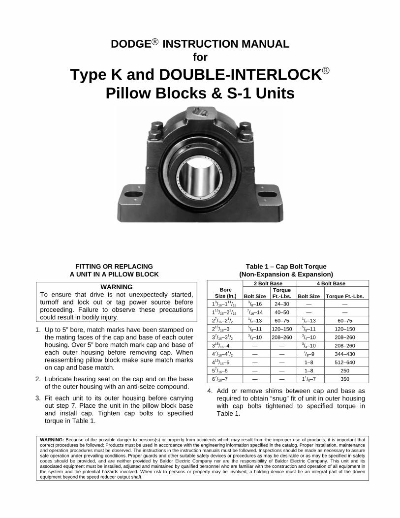
DODGE INSTRUCTION MANUAL for
Type K and DOUBLE-INTERLOCK Pillow Blocks & S-1 Units
FITTING OR REPLACING A UNIT IN A PILLOW BLOCK
WARNING To ensure that drive is not unexpectedly started, turnoff and lock out or tag power source before proceeding. Failure to observe these precautions could result in bodily injury.
1. Up to 5” bore, match marks have been stamped on the mating faces of the cap and base of each outer housing. Over 5” bore match mark cap and base of each outer housing before removing cap. When reassembling pillow block make sure match marks on cap and base match.
2. Lubricate bearing seat on the cap and on the base of the outer housing with an anti-seize compound.
3. Fit each unit to its outer housing before carrying out step 7. Place the unit in the pillow block base and install cap. Tighten cap bolts to specified torque in Table 1.
Table 1 – Cap Bolt Torque (Non-Expansion & Expansion)
2 Bolt Base 4 Bolt Base Bore
Size (In.)
Bolt Size Torque Ft.-Lbs. Bolt Size Torque Ft.-Lbs.
13/16–111/16 3/8–16 24–30 — —
115/16–23/16 7/16–14 40–50 — —
27/16–21/2 1/2–13 60–75 1/2–13 60–75
215/16–3 5/8–11 120–150 5/8–11 120–150
37/16–31/2 3/4–10 208–260 3/4–10 208–260
315/16–4 — — 3/4–10 208–260
47/16–41/2 — — 7/8–9 344–430
415/16–5 — — 1–8 512–640
57/16–6 — — 1–8 250
67/16–7 — — 11/8–7 350
4. Add or remove shims between cap and base as required to obtain “snug” fit of unit in outer housing with cap bolts tightened to specified torque in Table 1.
WARNING: Because of the possible danger to persons(s) or property from accidents which may result from the improper use of products, it is important that correct procedures be followed: Products must be used in accordance with the engineering information specified in the catalog. Proper installation, maintenance and operation procedures must be observed. The instructions in the instruction manuals must be followed. Inspections should be made as necessary to assure safe operation under prevailing conditions. Proper guards and other suitable safety devices or procedures as may be desirable or as may be specified in safety codes should be provided, and are neither provided by Baldor Electric Company nor are the responsibility of Baldor Electric Company. This unit and its associated equipment must be installed, adjusted and maintained by qualified personnel who are familiar with the construction and operation of all equipment in the system and the potential hazards involved. When risk to persons or property may be involved, a holding device must be an integral part of the driven equipment beyond the speed reducer output shaft.

3
5. Check fit by prying against lubrication stud in unit through the lubrication hole in housing cap with a screwdriver or small pinch bar depending upon the size of the pillow blocks.
6. The “snug” fit becomes a matter of judgment. A “loose or sloppy” fit may allow a unit mount to move in its outer housing thus wearing the mating surfaces. Too “tight” a fit will not allow the unit to move and compensate for misalignment and for shaft deflection caused by belt pull and dead weight.
7. Install bearings per installation instruction on following pages.
TABLE 2 Set Screw Torque
.sbL-.nI eziS5/16 561 3/8 092 1/2 026 5/8 5231 3/4 0512 7/8 0315
INSTALLATION INSTRUCTIONS (Medium Speed, Normal & Heavy Load)*
WARNING To ensure that drive is not unexpectedly started, turn off and lock out or tag power source before proceeding. Failure to observe these precautions could result in bodily injury.
1. Clean shaft and bore of bearing. Lubricate with light oil. 2. Slip bearing in position noting step 3. 3. Expansion Bearing: Loosen cap bolts in outer housing a
little so inner unit is free to align in outer housing. Outer housing shims provide a proper fit and must not be removed. Bolt outer housing to support. For heavy loads, use grade 8 base bolts.* Expansion type outer housings should be located so inner unit can move freely in either direction. Non-Expansion Bearings: Loosen cap bolts in outer housing a little so inner unit is free to align in outer housing. The hold-down bolts should be loose in the bolt holes. If the bolts are tight in bolt holes, the unit should be moved slightly on the shaft to provide looseness. This will help prevent preloading or inducing an initial thrust on bearings. Tighten nuts on holddown bolts. For heavy loads, use grade 8 base bolts.*
4. Tighten set screws to the torque values shown on Table 2. 5. Turn shaft several revolutions, or run shaft, if feasible and
safe, to allow alignment of inserts in their respective housings. Retighten cap bolts of both the expansion and the non-expansion outer housing to recommended torque in Table 1. Outer housing shims provide a proper fit and must not be removed.
6. The effort required to turn the shaft should be the same before and after bolting bearings to the support.
INSTALLATION INSTRUCTIONS (High Speed and/or Light Load)
Use this procedure for mounting pillow block bearings on horizontal or vertical applications, operating at high speed (above 75% of rated speed) or under light load (less than 2% of Dynamic Capacity).
WARNING To ensure that drive is not unexpectedly started, turn off and lock out or tag power source before proceeding. Failure to observe these precautions could result in bodily injury.
1. Shaft must be clean, free of burrs and lubricated. File nicks from housing bases.
2. Loosen setscrews (52) in collar (50) and slide bearings on shaft. If force is necessary, tap inner race only with a light drift. For vertical applications, locate adjusting nut (24) on bearing so nut faces upward.
3. Loosen housing cap bolt nuts one (1) turn. 4. Position expansion (floating) pillow block on mounting
surface and tighten base hold-down bolts. 5. Position non-expansion (fixed) pillow block in correct
relation to shaft and mounting surface. Tighten base holddown bolts, then torque setscrews (52) in collar per Table 2.
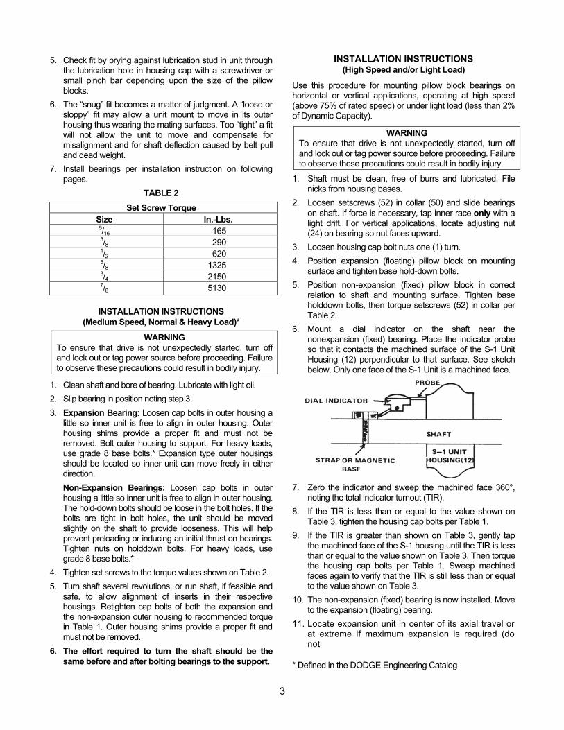
6. Mount a dial indicator on the shaft near the nonexpansion (fixed) bearing. Place the indicator probe so that it contacts the machined surface of the S-1 Unit Housing (12) perpendicular to that surface. See sketch below. Only one face of the S-1 Unit is a machined face.
7. Zero the indicator and sweep the machined face 360°, noting the total indicator turnout (TIR).
8. If the TIR is less than or equal to the value shown on Table 3, tighten the housing cap bolts per Table 1.
9. If the TIR is greater than shown on Table 3, gently tap the machined face of the S-1 housing until the TIR is less than or equal to the value shown on Table 3. Then torque the housing cap bolts per Table 1. Sweep machined faces again to verify that the TIR is still less than or equal to the value shown on Table 3.
10. The non-expansion (fixed) bearing is now installed. Move to the expansion (floating) bearing.
11. Locate expansion unit in center of its axial travel or at extreme if maximum expansion is required (do not
* Defined in the DODGE Engineering Catalog
4
preload stop pin) and torque collar setscrews (52) per Table 2.
12. Do not install external grease fittings until completion of final steps below.
13. Torque setscrews of expansion unit (Table 2).
14. Repeat Steps 6, 7, 8 and 9 for the expansion bearing.
15. The expansion (floating) bearing is now installed.
TABLE 3 Total Indicator Run-out (TIR)
Shaft Size (Inches)
TIR(Inches)
13/16 – 17/16 .0030 11/2 – 111/16 .0035 13/4 0400. 2 – 23/16 0400. 21/4 – 21/2 .0045 211/16 5500. 3 – 33/16 – 31/2 .0065 315/16 0700. 4 – 47/16 – 41/2 .0080 415/16 – 5 .0085
LUBRICATION INSTRUCTIONS Storage or Special Shutdown — If exposed to wet or dusty conditions or to corrosive vapors, extra protection is necessary. Add grease until it shows at the seals; rotate the bearing to distribute grease; cover the bearing. After storage or idle period, add a little fresh grease before running. During long idle periods, rotate shaft at least once a month. High Speed Operation — In the higher speed ranges too much grease will cause overheating. The amount of grease that the bearing will take for a particular high speed application can only be determined by experience — see “Operating Temperature” below. If excess grease in the bearing causes overheating, it will be necessary to remove grease fitting (also drain plug when furnished) to permit excess grease to escape. The bearing has been greased at the factory and is ready to run. When establishing a relubrication schedule, note that a small amount of grease at frequent intervals is preferable to a large amount at infrequent intervals. Operation in Presence of Dust, Water or Corrosive Vapors — Under these conditions the bearing should contain as much grease as speed will permit, since a full bearing with consequent slight leakage is the best protection against entrance of foreign material. In the higher speed ranges too much grease will cause overheating — see “High Speed Operation” above. In the lower speed ranges it is advisable to add extra
grease to a new bearing before putting into operation. Bearings should be greased as often as necessary (daily if required) to maintain a slight leakage at the seals. Average Operation — This bearing has been greased at the factory and is ready to run. The following table is a general guide for relubrication. However, certain conditions may require a change of lubricating periods as dictated by experience. See “High Speed Operation” and “Operation in Presence of Dust, Water or Corrosive Vapors” above. Operating Temperature — Abnormal bearing temperature may indicate faulty lubrication. Normal temperature may range from “cool to warm to the touch” up to a point “too hot to touch for more than a few seconds,” depending on bearing size and speed, and surrounding conditions. Unusually high temperature accompanied by excessive leakage of grease indicates too much grease. High temperature with no grease showing at the seals, particularly if the bearing seems noisy, usually indicates too little grease. Normal temperature and slight showing of grease at the seals indicate proper lubrication.
Lubrication Guide Read Preceding Paragraphs Before Establishing Lubrication Schedule.
Suggested Lubrication Period In Weeks HoursRun per
Day1 to 250RPM
251 to 500RPM
501 to 750RPM
751 to 1000RPM
1001 to 1500RPM
8 12 12 10 7 5 16 12 7 5 4 2 24 10 5 3 2 1
Kind of Grease — Many ordinary cup greases will disintegrate at speeds far below those at which DODGE bearings will operate successfully if proper grease is used. DODGE bearings have been lubricated at the factory with No. 2 consistency lithium complex-base grease which is suitable for normal operating conditions. Relubricate with lithium complex-base grease or a grease which is compatible with original lubricant and suitable for roller bearing service. In unusual or doubtful cases the recommendation of a reputable grease manufacturer should be secured.
Special Operating Conditions — Refer acid, chemical, extreme or other special operating conditions to DODGE, Greenville, SC 29602.
5
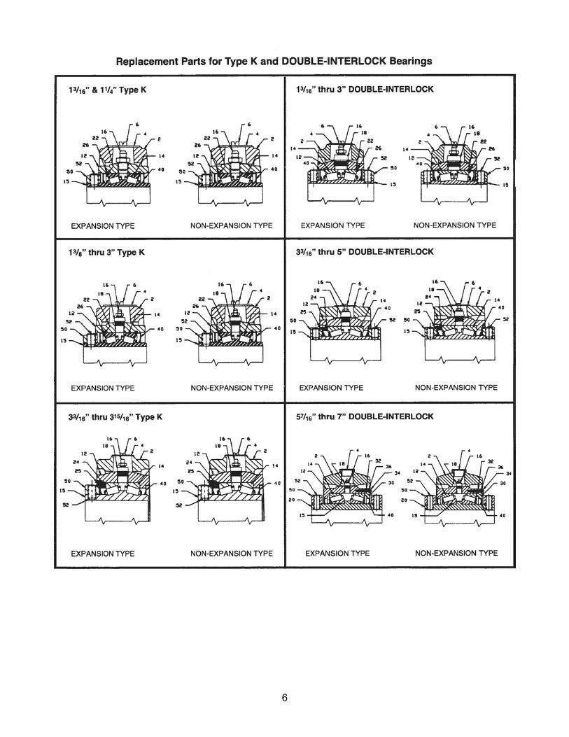
6

8
World HeadquartersP.O. Box 2400, Fort Smith, AR 72902-2400 U.S.A., Ph: (1) 479.646.4711, Fax (1) 479.648.5792, International Fax (1) 479.648.5895
Baldor - Dodge6040 Ponders Court, Greenville, SC 29615-4617 U.S.A., Ph: (1) 864.297.4800, Fax: (1) 864.281.2433
www.baldor.com
©Baldor Electric Company499798
All Rights Reserved. Printed in USA06/01/08 POD