Embed Size (px)
Citation preview
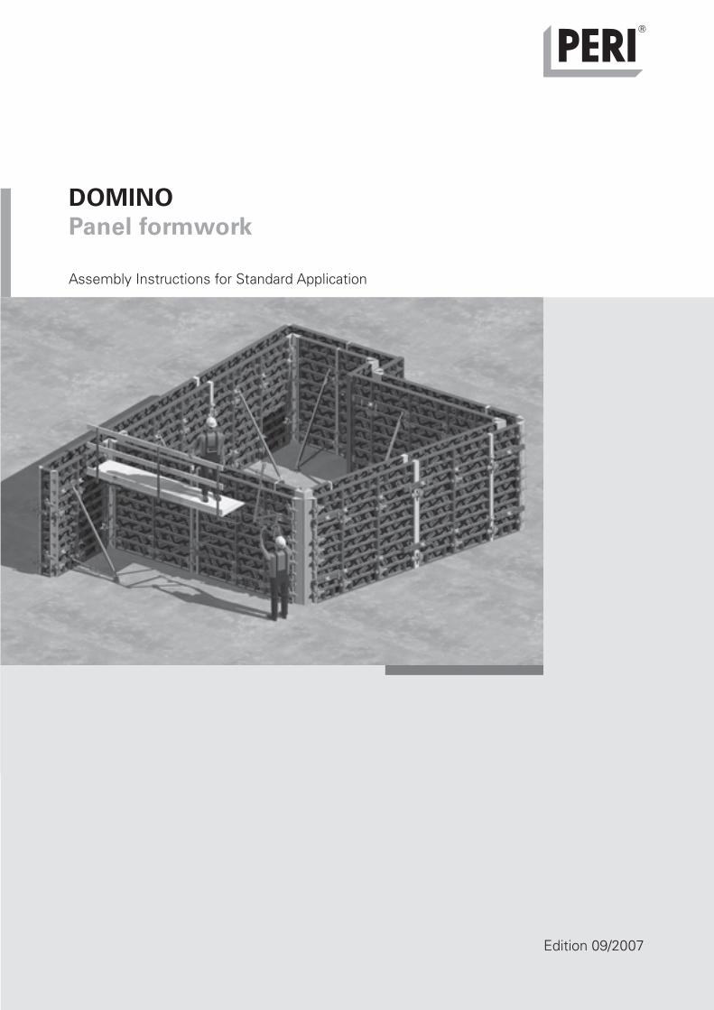
DOMINOPanel formwork
Assembly Instructions for Standard Application
Edition 09/2007
D d
09
/20
07
2m
a
Art
. N
r.:
79
219
6
© C
opyri
gh
t by P
ER
I G
mb
H
Titel_AuV_Domino mit U4.indd 2 17.09.2007 14:34:10 Uhr

Dokument 1 28.04.2005 12:48 Uhr Seite 1
Legend
Important safety Hints Visual Check Site Tipsinstructions
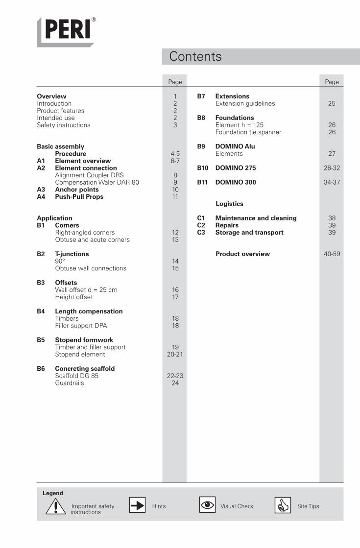
Page
B7 ExtensionsExtension guidelines 25
B8 FoundationsElement h = 125 26Foundation tie spanner 26
B9 DOMINO AluElements 27
B10 DOMINO 275 28-32
B11 DOMINO 300 34-37
Logistics
C1 Maintenance and cleaning 38C2 Repairs 39C3 Storage and transport 39
Product overview 40-59
Page
Overview 1Introduction 2Product features 2Intended use 2Safety instructions 3
Basic assemblyProcedure 4-5
A1 Element overview 6-7A2 Element connection
Alignment Coupler DRS 8Compensation Waler DAR 80 9
A3 Anchor points 10A4 Push-Pull Props 11
ApplicationB1 Corners
Right-angled corners 12Obtuse and acute corners 13
B2 T-junctions90° 14Obtuse wall connections 15
B3 OffsetsWall offset d = 25 cm 16Height offset 17
B4 Length compensationTimbers 18Filler support DPA 18
B5 Stopend formworkTimber and filler support 19Stopend element 20-21
B6 Concreting scaffoldScaffold DG 85 22-23Guardrails 24
Contents
1
A4
A3A2A1
B1
B2
B3
B4
B5
B6
B7
B5
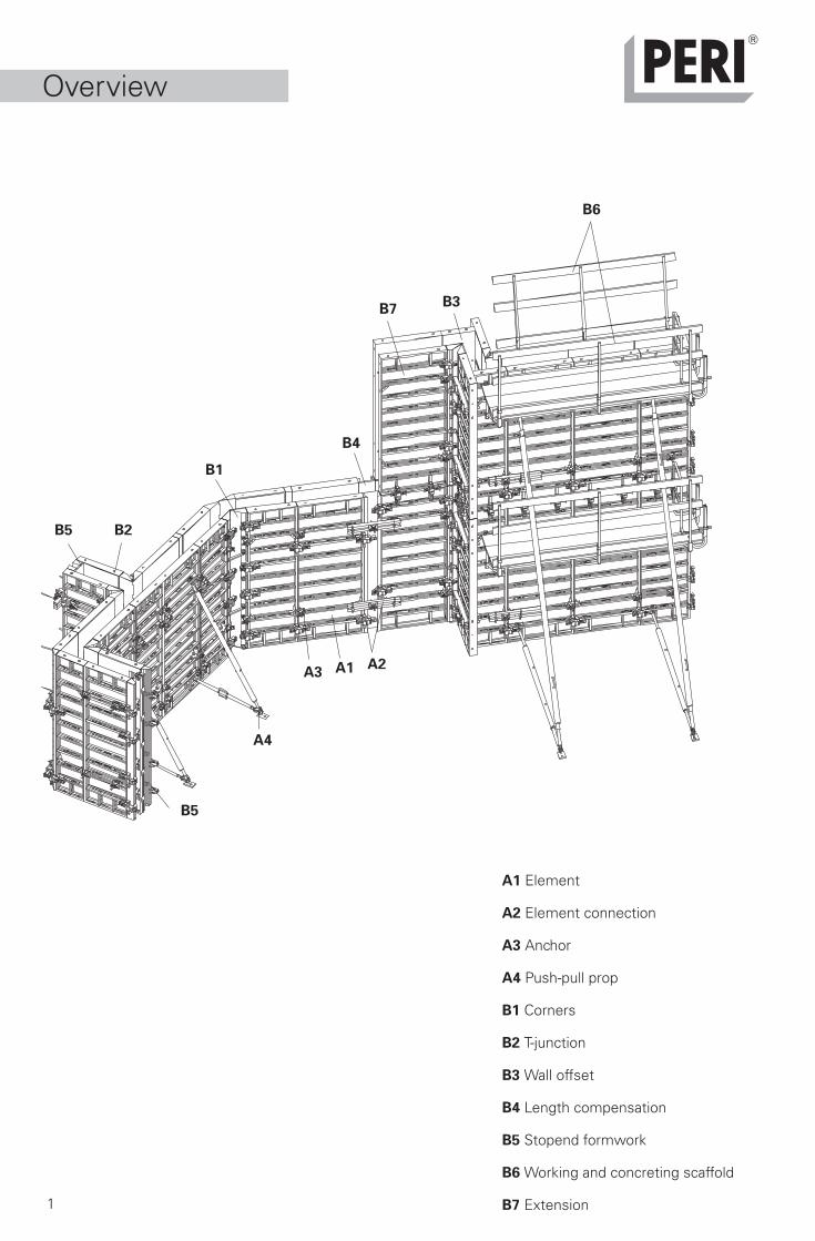
Overview
A1 Element
A2 Element connection
A3 Anchor
A4 Push-pull prop
B1 Corners
B2 T-junction
B3 Wall offset
B4 Length compensation
B5 Stopend formwork
B6 Working and concreting scaffold
B7 Extension
2
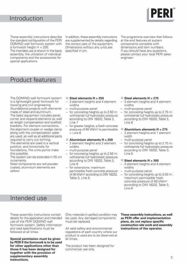
These assembly instructions describethe standard configuration of the PERIDOMINO wall formwork system witha formwork height H = 250.The intended use is shown in the basicassembly, the utilization of individualcomponents and the accessories forspecial applications.
Introduction
These assembly instructions containdetails for the application and intendeduse of the PERI DOMINO wallformwork system. Safety informationand load specifications must befollowed at all times.
Special permission must be givenby PERI if the formwork is to be usedfor other applications other thanthose it has been designed fortogether with the provision ofsupplementary assemblyinstructions.
Product features
In addition, these assembly instructionsare supplemented by details regardingthe correct care of the equipment.Dimensions without any units arespecified in cm.
The programme overview that followsat the end features all systemcomponents complete withdimensions and item numbers.If you should have any questions,please contact your local PERI salesengineer.
Intended use
Only materials in perfect condition maybe used. Any damaged componentsmust be replaced.
All valid safety and environmentalregulations of each country where ourproduct is used are to be observed atall times.
The product has been designed forcommercial use only.
These assembly instructions, as wellas PERI offer and implementationplans, do not replace specificconstruction site work and assemblyinstructions of the operator.
The DOMINO wall formwork systemis a lightweight panel formwork forhousing and civil engineering(foundations) projects with elementsmade of steel and aluminium.The basic equipment includes panel,corner and stopend elements as wellas length compensation and scaffoldbrackets. For element connections,the alignment coupler or wedge clampalong with the compensation walerare used, as well as all additional partsrequired to carry out forming.The elements are used in a verticalposition, and horizontally forfoundations. The units points makethis possible.The system can be extended in 25 cmincrements.Steel components are red powder-coated, aluminium elements areyellow.
Steel elements H = 250– 3 element heights and 4 element
widths– multi-purpose panel– for concreting heights up to 2.50 m:
withstands full hydrostatic pressureaccording to DIN 18202, Table 3,Line 7
– for greater heights, a fresh concretepressure of 60 kN/m2 is permissible= Line 6
Aluminium elements H = 250– 2 element heights and 2 element
widths– multi-purpose panel– for concreting heights up to 2.50 m:
withstands full hydrostatic pressureaccording to DIN 18202, Table 3,Line 6
– for extensions: maximumpermissible fresh concrete pressureof 50 kN/m2 according to DIN 18202,Table 3, Line 5
Steel elements H = 275– 3 element heights and 4 element
widths– multi-purpose panel– for concreting heights up to 2.75 m:
withstands full hydrostatic pressureaccording to DIN 18202, Table 3,Line 6
Aluminium elements H = 275– 2 element heights and 1 element
width– multi-purpose panel– for concreting heights up to 2.75 m:
withstands full hydrostatic pressureaccording to DIN 18202, Table 3,Line 6
Steel elements H = 300– 3 element heights and 4 element
widths– multi-purpose panel– for concreting heights up to 3.00 m:
maximum permissible freshconcrete pressure of 60 kN/m2
according to DIN 18202, Table 3,Line 6

Dokument 1 28.04.2005 12:48 Uhr Seite 1
3
Safety instructions
These assembly instructions aredirected at site personnel who workwith the DOMINO wall formworksystem.Non-observance of assemblyguidelines and safety informationcan lead to accidents and damageto materials.
Obligations of the operator:
1. The operator must ensure that allinstructions required for theduration of the project are at theuser´s disposal (includes the PERIassembly instructions).
2. All persons working with theproduct must be familiar with thecontent of these instructions andsafety information.
3. Persons who cannot or have greatdifficulty in reading andunderstanding these instructionsmust inform and then be fullybriefed by the operator.
4. The operator has to ensure thatassembly, adjusting anddismantling, moving as well asstandard use of the product issupervised by trained andauthorized personnel.
5. The operator is obliged to provideall prerequisites to ensurecompliance with applicable safetyregulations.
Safety instructions:
1. DOMINO components are to bechecked before every use to makesure they are in perfect condition!Damaged parts are to be replacedby PERI original components!
2. DOMINO is to be erected accordingto the assembly instructions toensure that all load effects are safelytransferred!
3. Ensure stability during all buildingphases!
4. Provide safe working areas forassembly, adjusting anddismantling, as well as moving!(See safety information valid foreach individual country)
5. Safe access ways must be providedfor site personnel to reach allworking areas!
6. Safety barriers must be installedon all working areas to prevent sitepersonnel from falling!
7. Avoid using areas of risk duringunfavourable weather conditions!
8. Striking only takes place when theconcrete is hard enough and sitemanagement has given the go-ahead!
9. Use suitable tools and equipmentduring striking and moving! Do nottear away formwork elements fromthe concreted wall with the crane!
10.Do not put the stability of thestructural elements, scaffolding andformwork components at riskduring striking!
11. Only transport formworkcomponents with hoisting and load-carrying equipment if suitableattachment possibilities areavailable!
12.The weight of the componentsmust not exceed the permissibleload capacity of the lifting gear!
13.Remove any loose parts or secureaccordingly to prevent them fallingoff!
14.Remove lifting accessories from alowered formwork component orunit only when it is in a stableposition!
15.Formwork elements are to beguided with ropes during strongwind conditions! Avoid anycollisions with other objects!
16.Components must be stored andtransported in a stable position toavoid any unintentional movement!
Care instructions for the formlining
An immersion vibrator complete withrubber cap minimizes any damage tothe formlining.
Spacers with large support plates forreinforcement reduce indentations
Additional regulations:
Currently, the following is of particularimportance:– German Health and Safety at Work
Regulations (BetrSichV)– Technical Guidelines for Health and
Safety at Work (TRBS)
Further applicablePERI product information
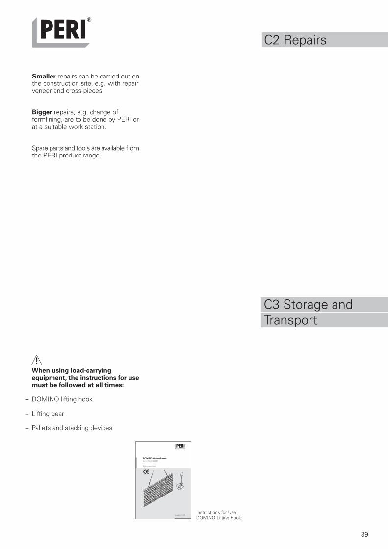
Instructions for Use:DOMINO Lifting HookPallets and Stacking Devices
Technical dataFormwork Tables
4
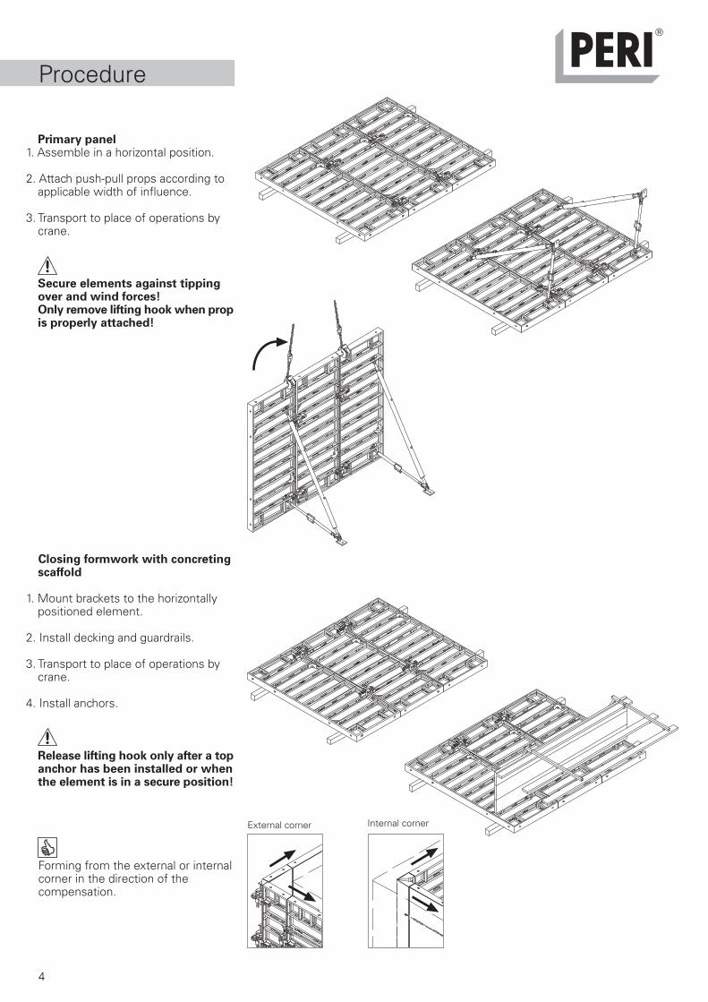
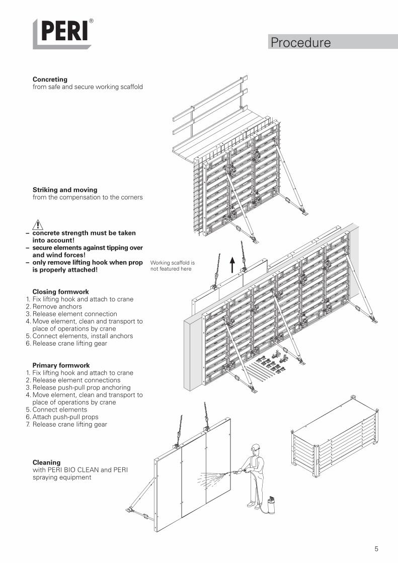
Procedure
Primary panel1. Assemble in a horizontal position.
2. Attach push-pull props according toapplicable width of influence.
3. Transport to place of operations bycrane.
Secure elements against tippingover and wind forces!Only remove lifting hook when propis properly attached!
Closing formwork with concretingscaffold
1. Mount brackets to the horizontallypositioned element.
2. Install decking and guardrails.
3. Transport to place of operations bycrane.
4. Install anchors.
Release lifting hook only after a topanchor has been installed or whenthe element is in a secure position!
Forming from the external or internalcorner in the direction of thecompensation.
External corner Internal corner
5
Procedure
Concretingfrom safe and secure working scaffold
Striking and movingfrom the compensation to the corners
– concrete strength must be takeninto account!
– secure elements against tipping overand wind forces!
– only remove lifting hook when propis properly attached!
Closing formwork1. Fix lifting hook and attach to crane2. Remove anchors3. Release element connection4. Move element, clean and transport to
place of operations by crane5. Connect elements, install anchors6. Release crane lifting gear
Primary formwork1. Fix lifting hook and attach to crane2. Release element connections3. Release push-pull prop anchoring4. Move element, clean and transport to
place of operations by crane5. Connect elements6. Attach push-pull props7. Release crane lifting gear
Cleaningwith PERI BIO CLEAN and PERIspraying equipment
Working scaffold isnot featured here
6
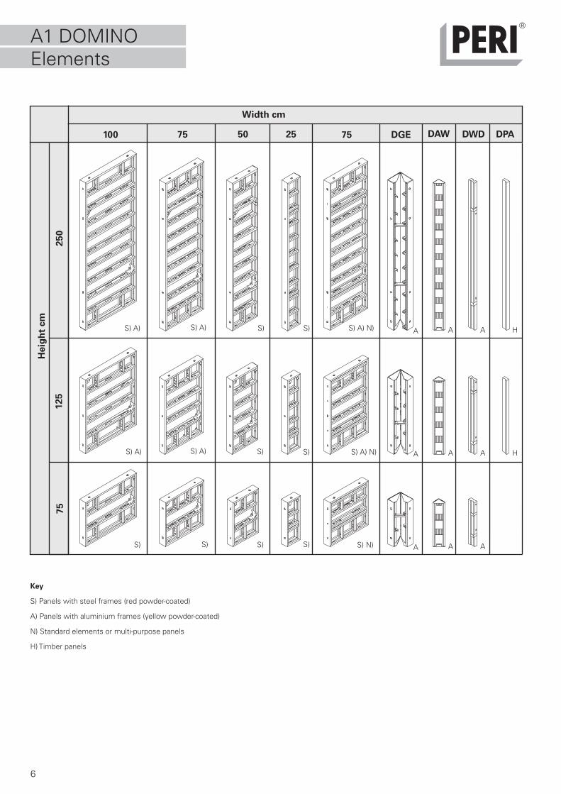
A1 DOMINOElements
Key
S) Panels with steel frames (red powder-coated)
A) Panels with aluminium frames (yellow powder-coated)
N) Standard elements or multi-purpose panels
H) Timber panels
75100 50 7525 DGE DAW DWD
250
125
75
Heig
ht
cm
S)S)S) A)
S) A) S) A)
S) A)
DPA
S) S)
S) A) N)
S) A) N) A A A H
S) N)
A A A H
A A AS)S)S)S)
Width cm
7
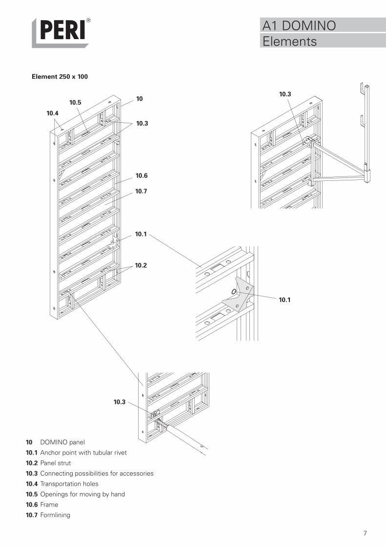
10.1
10
10.2
10.3
10.4
10.6
10.3
10.7
10.3
10.1
10.5
Element 250 x 100
A1 DOMINOElements
10 DOMINO panel
10.1 Anchor point with tubular rivet
10.2 Panel strut
10.3 Connecting possibilities for accessories
10.4 Transportation holes
10.5 Openings for moving by hand
10.6 Frame
10.7 Formlining
8
20
20.3
20
20.4
20.2
20.1
1
3
2
20
A2 ElementConnection
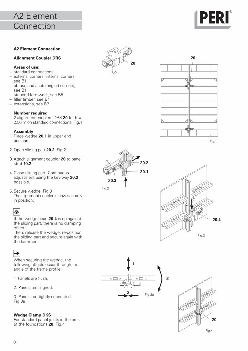
A2 Element Connection
Alignment Coupler DRS
Areas of use:– standard connections– external corners, internal corners,
see B1– obtuse and acute-angled corners,
see B1– stopend formwork, see B5– filler timber, see B4– extensions, see B7
Number required2 alignment couplers DRS 20 for h =2.50 m on standard connections, Fig.1
Assembly1. Place wedge 20.1 in upper end
position.
2. Open sliding part 20.2. Fig.2
3. Attach alignment coupler 20 to panelstrut 10.2.
4. Close sliding part. Continuousadjustment using the key-way 20.3possible.
5. Secure wedge, Fig.3The alignment coupler is now securelyin position.
If the wedge head 20.4 is up againstthe sliding part, there is no clampingeffect!Then: release the wedge, re-positionthe sliding part and secure again withthe hammer.
When securing the wedge, thefollowing effects occur through theangle of the frame profile:
1. Panels are flush.
2. Panels are aligned.
3. Panels are tightly connected.Fig.3a
Wedge Clamp DKSFor standard panel joints in the areaof the foundations 20, Fig.4
Fig.1
Fig.2
Fig.3
Fig.4
Fig.3a
9
21
10.3
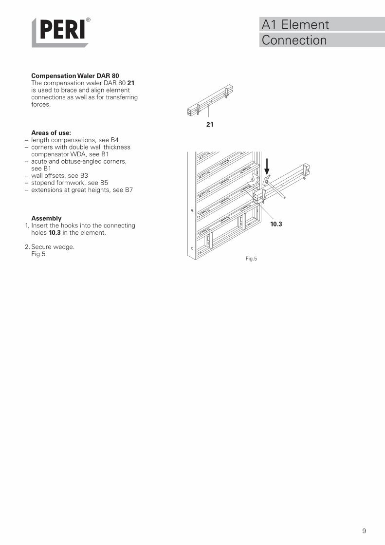
Compensation Waler DAR 80The compensation waler DAR 80 21is used to brace and align elementconnections as well as for transferringforces.
Areas of use:– length compensations, see B4– corners with double wall thickness
compensator WDA, see B1– acute and obtuse-angled corners,
see B1– wall offsets, see B3– stopend formwork, see B5– extensions at great heights, see B7
Assembly1. Insert the hooks into the connecting
holes 10.3 in the element.
2. Secure wedge.Fig.5
Fig.5
A1 ElementConnection
34
30
10
35
31
32
33
A3 Anchor points
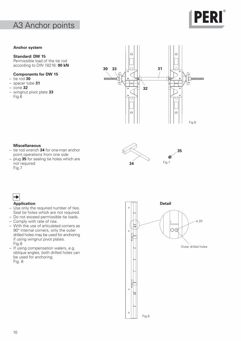
Anchor system
Standard: DW 15Permissible load of the tie rodaccording to DIN 18216: 90 kN
Components for DW 15– tie rod 30– spacer tube 31– cone 32– wingnut pivot plate 33
Fig.6
Miscellaneous– tie rod wrench 34 for one-man anchor
point operations from one side– plug 35 for sealing tie holes which are
not requiredFig.7
Application– Use only the required number of ties. Seal tie holes which are not required.– Do not exceed permissible tie loads.– Comply with rate of rise.– With the use of articulated corners as
90° internal corners, only the outerdrilled holes may be used for anchoringif using wingnut pivot plates.Fig.8
– If using compensation walers, e.g.oblique angles, both drilled holes canbe used for anchoring.Fig. 8
Fig.6
Fig.7
Fig.8
Outer drilled holes
ø 20
Detail
11
41
x =
y =
4.0 5.0
1.82
5.0
1.2
1.2
1.0
1.41
5.0
1.2
1.6
1.2
1.12
5.0
1.2
2.0
1.5
3.0
h
y
x
FAV
FRS
0.5
kN/m
2
60°
40
41
42
40
43 44
45
A4 Push-Pull Props
Push-pull props and kicker braces areto be installed for aligning the DOMINOformwork as well as providing stabilityand to counter the effects of windloads. The choice of push-pull prop andkicker brace depends on the formworkheight.
Assembly
Push-Pull Prop Connector DRAFig. 9
Push-pull props and kicker braces areattached to the elements by means ofthe push-pull prop connector 41.Connections are also possible usingthe horizontal panel struts.Fig.10a
1. Place the cam lock 42 in a vertical position.
2. Insert the push-pull prop connectorfrom below through the connecting hole.
3. Turn the cam lock to a horizontalposition and secure.
Push-pull props and kicker bracesFig.10
1. Attach push-pull prop 40 or kicker braceto the connecting plate 43 using pinsand cotter pins 44. Fig.10b
2. Fix base plate, e.g. with PERIMulti Monti 45. Fig.10c
Fig.9
Permissible push-pull prop spacings
For the given widths of influence, a maximum forceof 11.3 kN is transferred into the building at the footof the push-pull prop.Perm. F (all directions) Hilti HKD M20 x 80 (B25)5.8 kN.Recommended F (all directions) anchor bolt MMS20x130 for concrete
with ß w > 20N/mm2 11.3 kNWind loads: h < 8m = 0.5 kN/m2
8m< h < 20m = 0.8 kN/m2
For formwork heights up to 8.0 m:If the dynamic pressure deviates from 0.5 kN/m2,the widths of influence can be changedproportionately from the existing dynamic pressureto 0.5 kN/m2.
Fig.10a
Fig.10c
Fig.10b
Formwork height h [m]
Max. width of influence [m]
Actual prop load FRS
at maximum prop spacing
Actual kicker brace load FAV
[kN]at maximum prop spacing
distance of base plate [m]from rear edge of formwork
distance of top connectionpoint [m] from top of formwork
Fig.10
12
11
18
12
20
1320 13.1
13.1
50
18
18 18
18
18
50
20 24
3035
50
50
50
50
50
50
50
50
50
50
50 50
25
36,5
50
50
B1 Corners
Fig.11a - 11f
Fig.12
Fig.13
5050
90°
DWD 5 Filler timber 1 cm
DWD 5
DWD 5 2 DWD 5
2 DWD 5
2 DWD 5
Timber 11,5 cm
Filler timber 1,5 cm
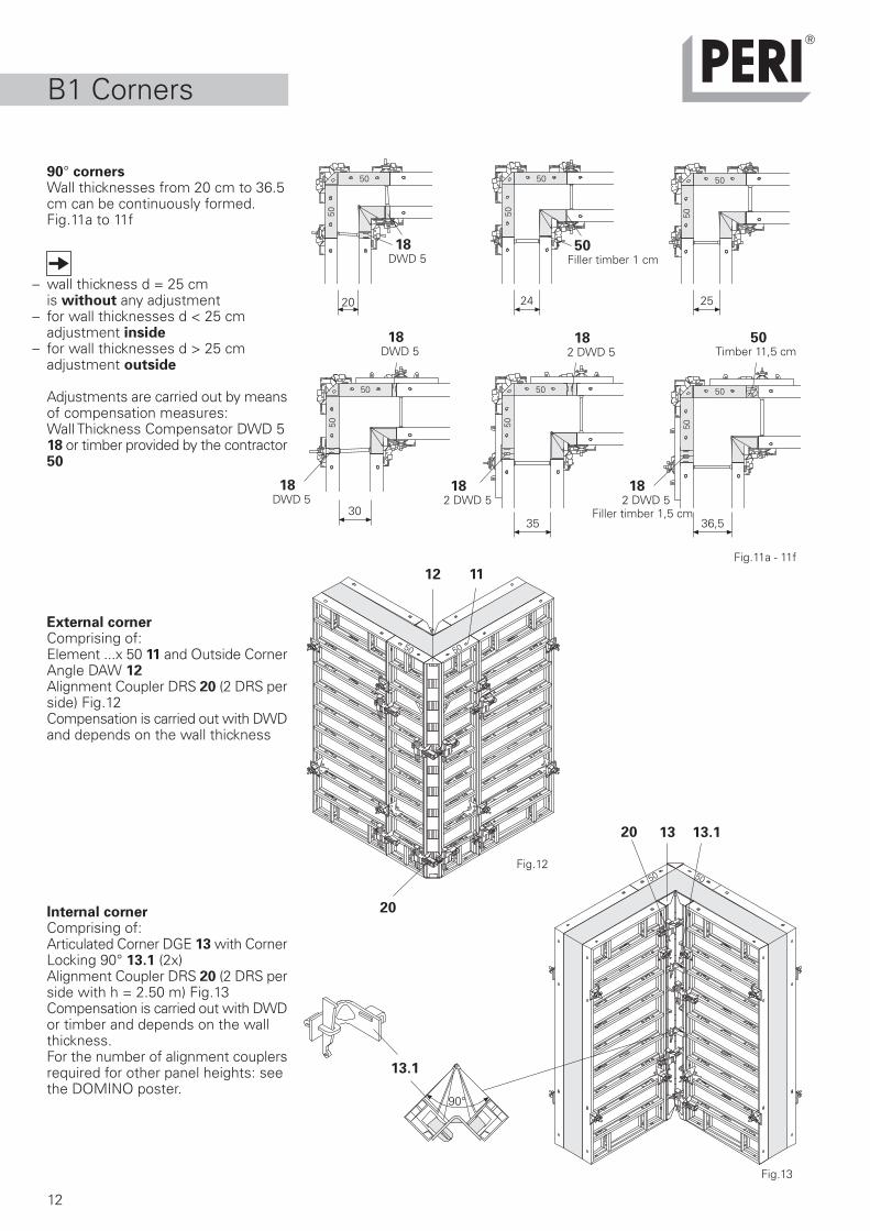
90° cornersWall thicknesses from 20 cm to 36.5cm can be continuously formed.Fig.11a to 11f
– wall thickness d = 25 cm is without any adjustment– for wall thicknesses d < 25 cm adjustment inside– for wall thicknesses d > 25 cm
adjustment outside
Adjustments are carried out by meansof compensation measures:Wall Thickness Compensator DWD 518 or timber provided by the contractor50
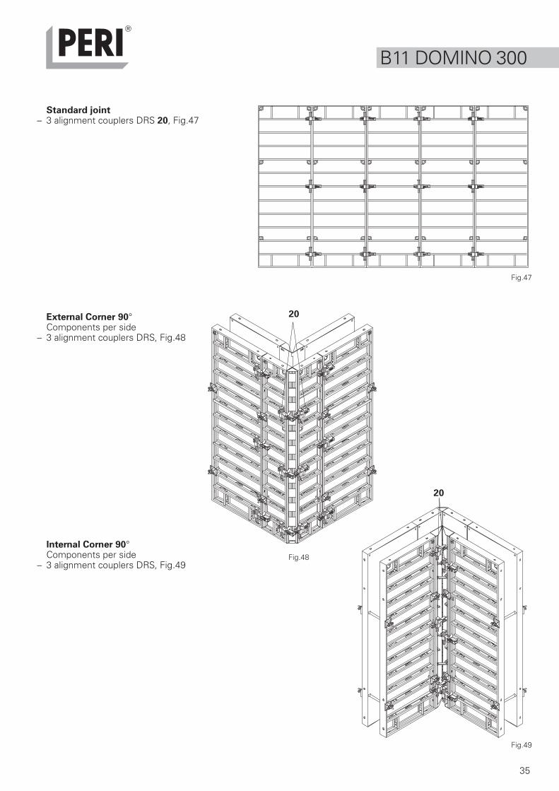
External cornerComprising of:Element ...x 50 11 and Outside CornerAngle DAW 12Alignment Coupler DRS 20 (2 DRS perside) Fig.12Compensation is carried out with DWDand depends on the wall thickness
Internal cornerComprising of:Articulated Corner DGE 13 with CornerLocking 90° 13.1 (2x)Alignment Coupler DRS 20 (2 DRS perside with h = 2.50 m) Fig.13Compensation is carried out with DWDor timber and depends on the wallthickness.For the number of alignment couplersrequired for other panel heights: seethe DOMINO poster.
13
13 20
13.1
23
13 13.1
135°
135°
13.1
B1 Corners
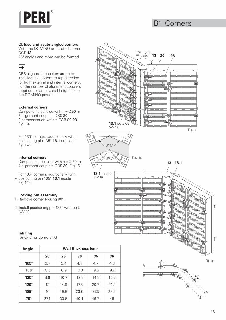
Obtuse and acute-angled cornersWith the DOMINO articulated cornerDGE 1375° angles and more can be formed.
DRS alignment couplers are to beinstalled in a bottom to top directionfor both external and internal corners.For the number of alignment couplersrequired for other panel heights: seethe DOMINO poster.
External cornersComponents per side with h = 2.50 m
– 5 alignment couplers DRS 20– 2 compensation walers DAR 80 23
Fig. 14
For 135° corners, additionally with:– positioning pin 135° 13.1 outside
Fig.14a
Internal cornersComponents per side with h = 2.50 m
– 4 alignment couplers DRS 20, Fig.15
For 135° corners, additionally with:– positioning pin 135° 13.1 inside
Fig.14a
Locking pin assembly1. Remove corner locking 90°.
2. Install positioning pin 135° with bolt,SW 19.
Fig.14
Infillingfor external corners (X)
min 75°max 165°
Fig.15
Wall thickness (cm)Angle
150° 5.6 6.9 8.3 9.6 9.9
135° 8.6 10.7 12.8 14.8 15.2
120° 12 14.9 17.8 20.7 21.2
165° 2.7 3.4 4.1 4.7 4.8
105° 16 19.8 23.6 27.5 28.2
75° 27.1 33.6 40.1 46.7 48
SW 19
Fig.14a
75
75
75
75
SW 19
x
x
20 25 30 35 36
inside
outside
14
50
13
18
15
13
13
15
13 5013
15
13
18
13
15
13
18
13
15
13 13
15
13
18
2455
75
B2 T-junctions
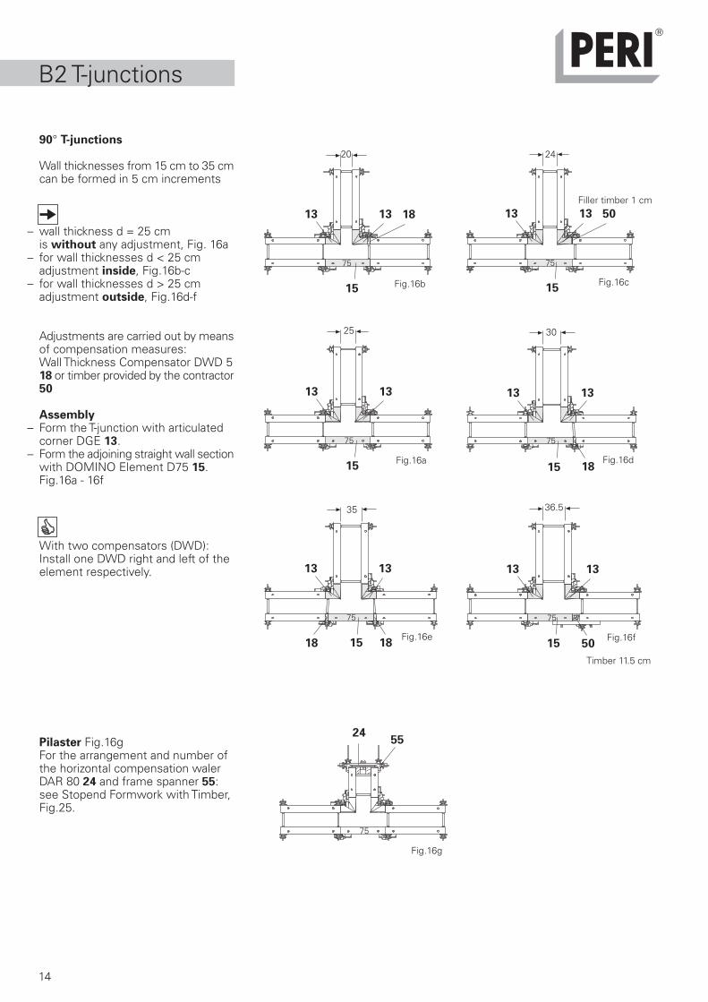
90° T-junctions
Wall thicknesses from 15 cm to 35 cmcan be formed in 5 cm increments
– wall thickness d = 25 cm is without any adjustment, Fig. 16a– for wall thicknesses d < 25 cm adjustment inside, Fig.16b-c– for wall thicknesses d > 25 cm adjustment outside, Fig.16d-f
Adjustments are carried out by meansof compensation measures:Wall Thickness Compensator DWD 518 or timber provided by the contractor50
Assembly– Form the T-junction with articulated
corner DGE 13.– Form the adjoining straight wall section
with DOMINO Element D75 15.Fig.16a - 16f
With two compensators (DWD):Install one DWD right and left of theelement respectively.
Pilaster Fig.16gFor the arrangement and number ofthe horizontal compensation walerDAR 80 24 and frame spanner 55:see Stopend Formwork with Timber,Fig.25.
Fig.16a
20 24
25 30
35 36.5
75
75 75
75
75 75
Fig.16b Fig.16c
Fig.16d
Fig.16e Fig.16f
Filler timber 1 cm
Timber 11.5 cm
Fig.16g
15
19
18
B2 T-junctions
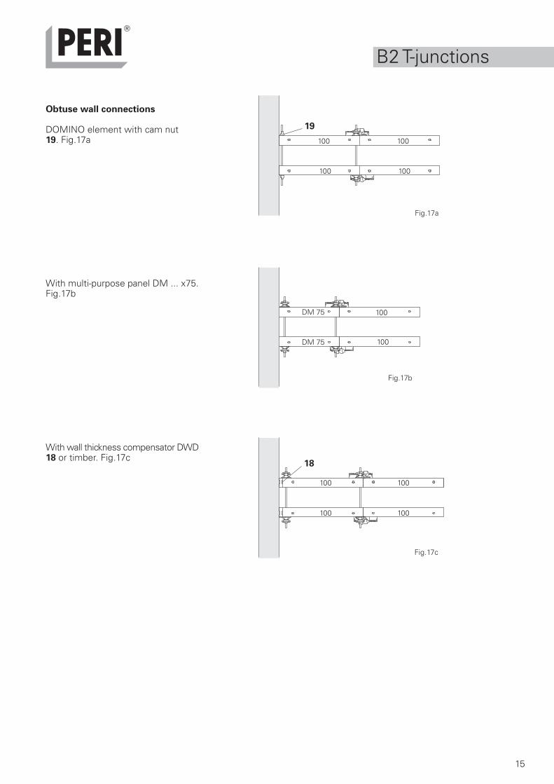
Obtuse wall connections
DOMINO element with cam nut19. Fig.17a
With multi-purpose panel DM ... x75.Fig.17b
With wall thickness compensator DWD18 or timber. Fig.17c
Fig.17a
100
100
100
100
100 100
100 100
DM 75
100
100
Fig.17b
Fig.17c
DM 75
16
21
2129 512050
21 2951 20 50
10
25
10
21
25
12
21
50
12
50
21
13
17
17
8313
13
13
25-3
7
B3 Offsets
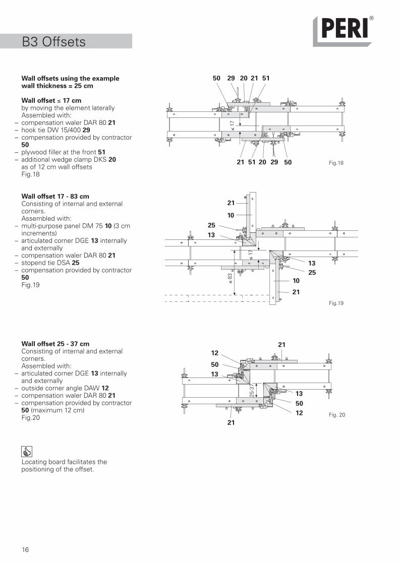
Wall offsets using the examplewall thickness = 25 cm
Wall offset 17 cmby moving the element laterallyAssembled with:
– compensation waler DAR 80 21– hook tie DW 15/400 29– compensation provided by contractor
50– plywood filler at the front 51– additional wedge clamp DKS 20
as of 12 cm wall offsetsFig.18
Wall offset 17 - 83 cmConsisting of internal and externalcorners.Assembled with:
– multi-purpose panel DM 75 10 (3 cmincrements)
– articulated corner DGE 13 internallyand externally
– compensation waler DAR 80 21– stopend tie DSA 25– compensation provided by contractor
50Fig.19
Wall offset 25 - 37 cmConsisting of internal and externalcorners.Assembled with:
– articulated corner DGE 13 internallyand externally
– outside corner angle DAW 12– compensation waler DAR 80 21– compensation provided by contractor
50 (maximum 12 cm)Fig.20
Locating board facilitates thepositioning of the offset.
Fig.18
Fig. 20
Fig.19
17
20
20
B3 Offsets
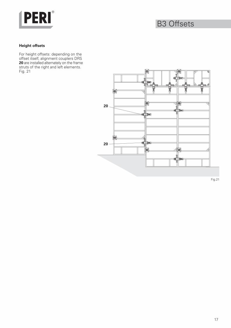
Height offsets
For height offsets: depending on theoffset itself, alignment couplers DRS20 are installed alternately on the framestruts of the right and left elements.Fig. 21
Fig.21
18
5020
53
51 21
B4 LengthCompensation
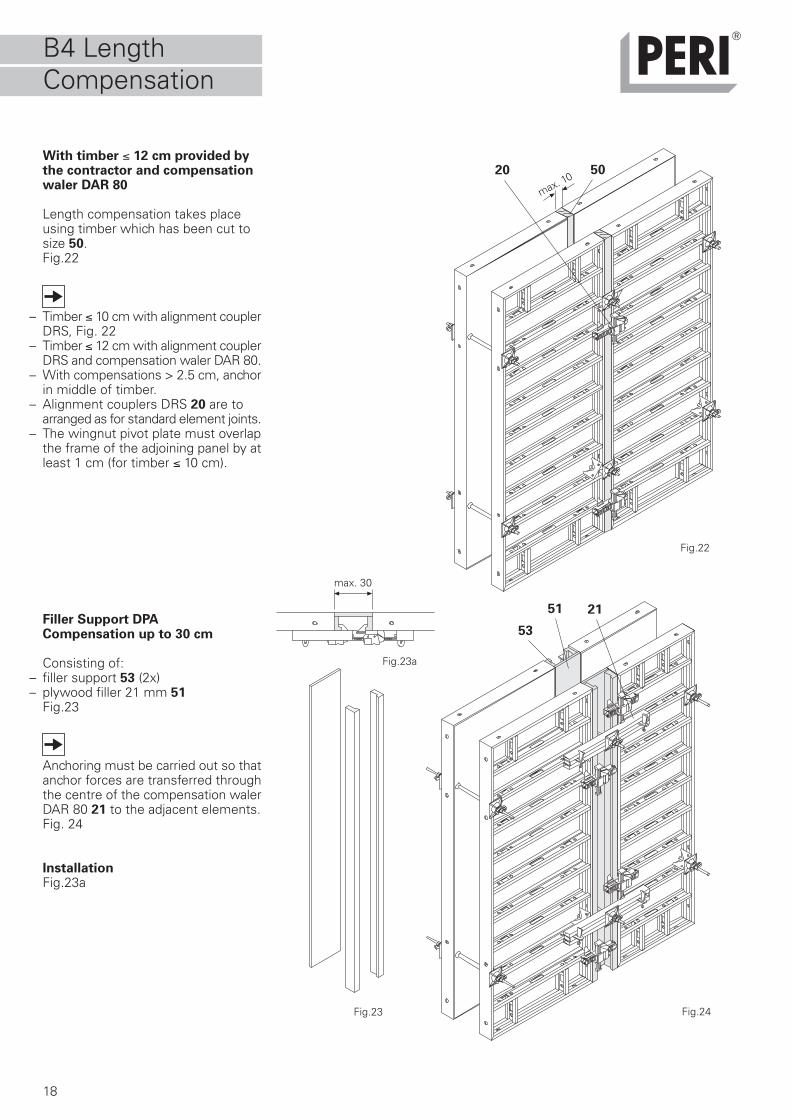
With timber 12 cm provided bythe contractor and compensationwaler DAR 80
Length compensation takes placeusing timber which has been cut tosize 50.Fig.22
– Timber 10 cm with alignment couplerDRS, Fig. 22
– Timber 12 cm with alignment couplerDRS and compensation waler DAR 80.
– With compensations > 2.5 cm, anchorin middle of timber.
– Alignment couplers DRS 20 are toarranged as for standard element joints.
– The wingnut pivot plate must overlapthe frame of the adjoining panel by atleast 1 cm (for timber 10 cm).
Fig.22
Fig.23
Filler Support DPACompensation up to 30 cm
Consisting of:– filler support 53 (2x)– plywood filler 21 mm 51
Fig.23
Anchoring must be carried out so thatanchor forces are transferred throughthe centre of the compensation walerDAR 80 21 to the adjacent elements.Fig. 24
InstallationFig.23a
max. 30
Fig.23a
Fig.24
max. 10
19
24
25
55
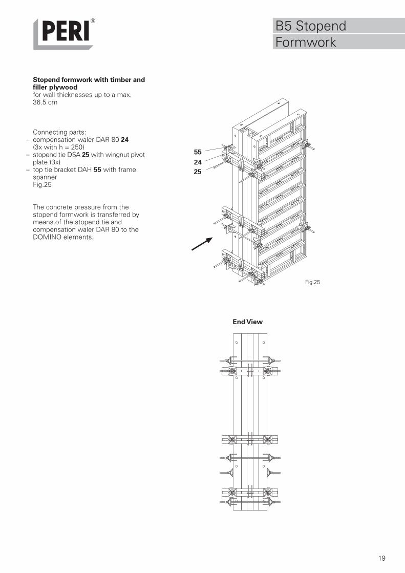
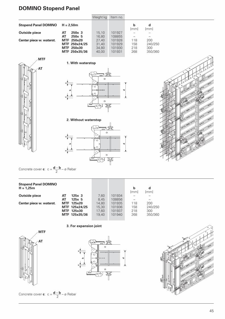
Stopend formwork with timber andfiller plywoodfor wall thicknesses up to a max.36.5 cm
Connecting parts:– compensation waler DAR 80 24
(3x with h = 250)– stopend tie DSA 25 with wingnut pivot
plate (3x)– top tie bracket DAH 55 with frame
spannerFig.25
The concrete pressure from thestopend formwork is transferred bymeans of the stopend tie andcompensation waler DAR 80 to theDOMINO elements.
Fig.25
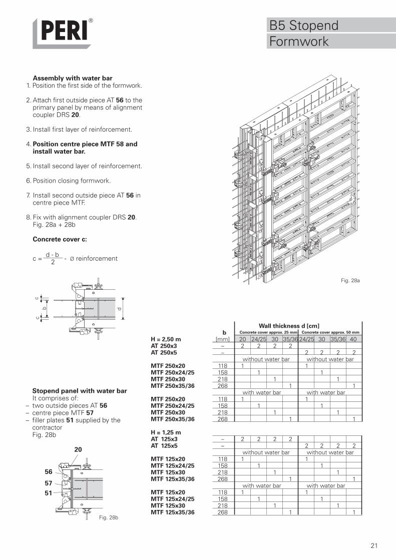
B5 StopendFormwork
End View
20
20
56.1 MTF
AT
MTF
AT56
57
56 57
57
56.1
56
B5 StopendFormwork
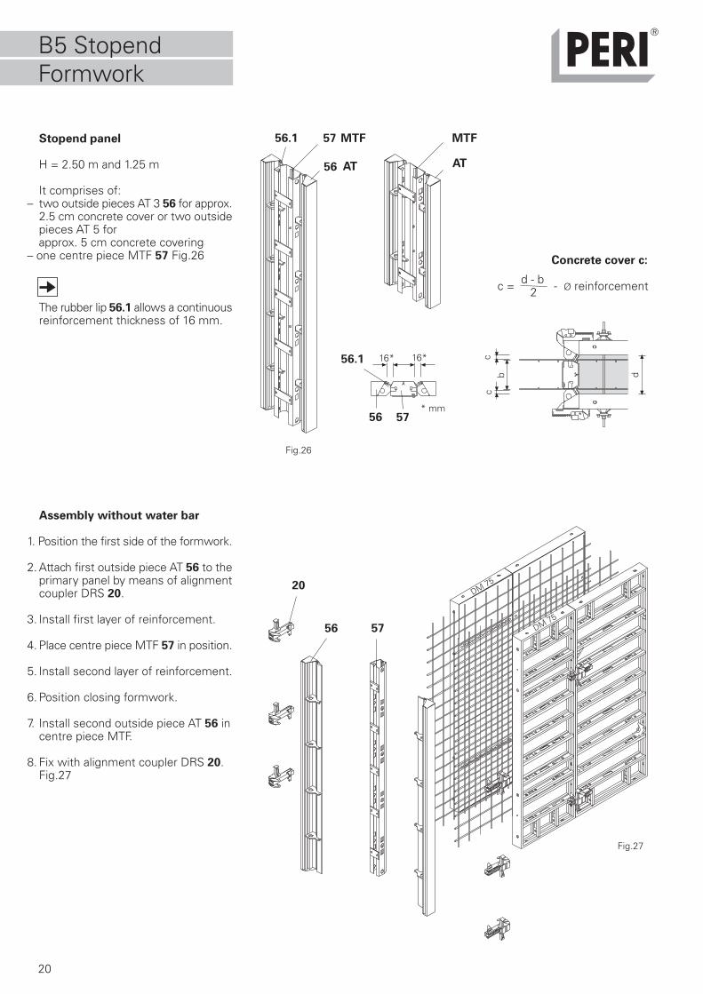
Stopend panel
H = 2.50 m and 1.25 m
It comprises of:– two outside pieces AT 3 56 for approx.
2.5 cm concrete cover or two outsidepieces AT 5 forapprox. 5 cm concrete covering
– one centre piece MTF 57 Fig.26
The rubber lip 56.1 allows a continuousreinforcement thickness of 16 mm.
Assembly without water bar
1. Position the first side of the formwork.
2. Attach first outside piece AT 56 to theprimary panel by means of alignmentcoupler DRS 20.
3. Install first layer of reinforcement.
4. Place centre piece MTF 57 in position.
5. Install second layer of reinforcement.
6. Position closing formwork.
7. Install second outside piece AT 56 incentre piece MTF.
8. Fix with alignment coupler DRS 20.Fig.27
Fig.26
Fig.27
Concrete cover c:
dbc
c
c = d - b - Ø reinforcement2
* mm
16* 16*
DM 75
DM 75
21
dbc
cB5 StopendFormwork
Assembly with water bar1. Position the first side of the formwork.
2. Attach first outside piece AT 56 to theprimary panel by means of alignmentcoupler DRS 20.
3. Install first layer of reinforcement.
4. Position centre piece MTF 58 andinstall water bar.
5. Install second layer of reinforcement.
6. Position closing formwork.
7. Install second outside piece AT 56 incentre piece MTF.
8. Fix with alignment coupler DRS 20.Fig. 28a + 28b
Concrete cover c:
Fig. 28a
c = d - b - Ø reinforcement2
Stopend panel with water barIt comprises of:
– two outside pieces AT 56– centre piece MTF 57– filler plates 51 supplied by the
contractorFig. 28b
51
57
20
56
Fig. 28b
Wall thickness d [cm]b Concrete cover approx. 25 mm Concrete cover approx. 50 mm
H = 2,50 m [mm] 20 24/25 30 35/36 24/25 30 35/36 40AT 250x3 – 2 2 2 2AT 250x5 – 2 2 2 2
without water bar without water barMTF 250x20 118 1 1MTF 250x24/25 158 1 1MTF 250x30 218 1 1MTF 250x35/36 268 1 1
with water bar with water barMTF 250x20 118 1 1MTF 250x24/25 158 1 1MTF 250x30 218 1 1MTF 250x35/36 268 1 1
H = 1,25 mAT 125x3 – 2 2 2 2AT 125x5 – 2 2 2 2
without water bar without water barMTF 125x20 118 1 1MTF 125x24/25 158 1 1MTF 125x30 218 1 1MTF 125x35/36 268 1 1
with water bar with water barMTF 125x20 118 1 1MTF 125x24/25 158 1 1MTF 125x30 218 1 1MTF 125x35/36 268 1 1
22
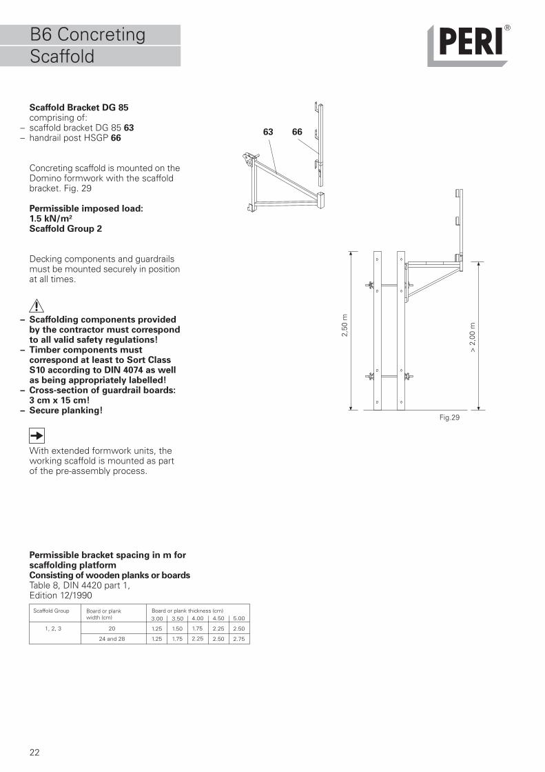
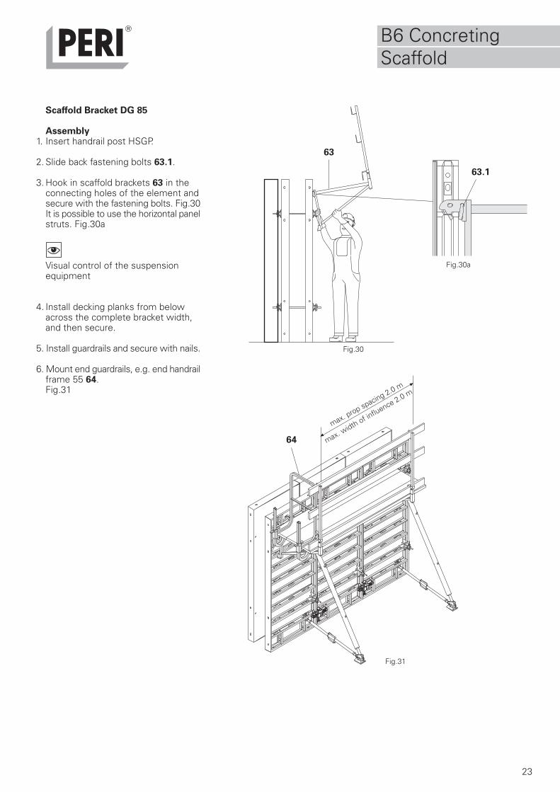
63 66
Scaffold Bracket DG 85comprising of:
– scaffold bracket DG 85 63– handrail post HSGP 66
Concreting scaffold is mounted on theDomino formwork with the scaffoldbracket. Fig. 29
Permissible imposed load:1.5 kN/m2
Scaffold Group 2
Decking components and guardrailsmust be mounted securely in positionat all times.
– Scaffolding components providedby the contractor must correspondto all valid safety regulations!
– Timber components mustcorrespond at least to Sort ClassS10 according to DIN 4074 as wellas being appropriately labelled!
– Cross-section of guardrail boards: 3 cm x 15 cm!
– Secure planking!
With extended formwork units, theworking scaffold is mounted as partof the pre-assembly process.
Permissible bracket spacing in m forscaffolding platformConsisting of wooden planks or boardsTable 8, DIN 4420 part 1,Edition 12/1990
3.00
1.25
1.25
4.00
1.75
2.25
1, 2, 3 20
24 and 28
3.50
1.50
1.75
4.50
2.25
2.50
5.00
2.50
2.75
Fig.29
2,50
m
> 2
,00
m
Board or plank thickness (cm)Board or plankwidth (cm)
Scaffold Group
B6 ConcretingScaffold
23
63
63.1
64
Scaffold Bracket DG 85
Assembly1. Insert handrail post HSGP.
2. Slide back fastening bolts 63.1.
3. Hook in scaffold brackets 63 in the connecting holes of the element andsecure with the fastening bolts. Fig.30It is possible to use the horizontal panelstruts. Fig.30a
Visual control of the suspensionequipment
4. Install decking planks from belowacross the complete bracket width,and then secure.
5. Install guardrails and secure with nails.
6. Mount end guardrails, e.g. end handrailframe 55 64.Fig.31
Fig.30
Fig.30a
Fig.31
max. prop spacing 2.0 m
max. width of in
fluence 2.0 m
B6 ConcretingScaffold
24
66
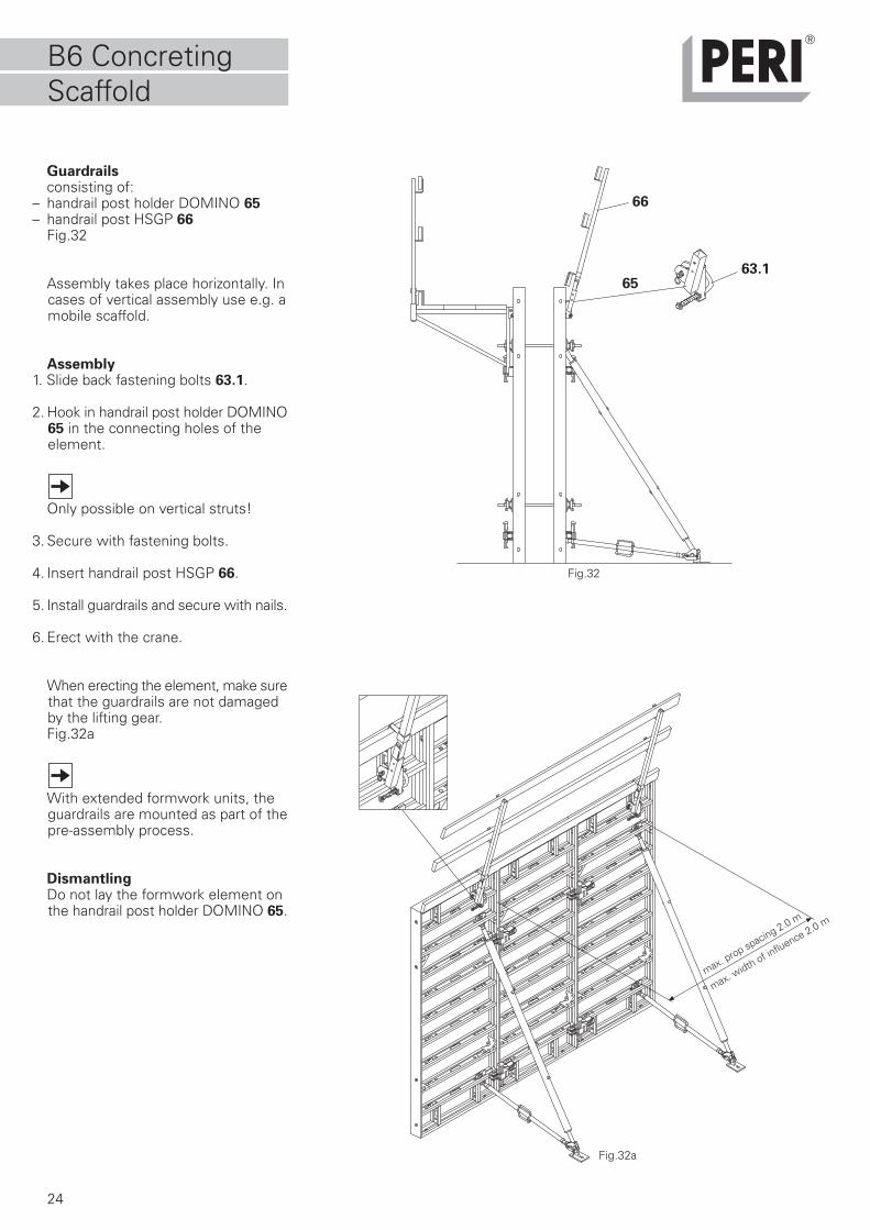
6563.1
Guardrailsconsisting of:
– handrail post holder DOMINO 65– handrail post HSGP 66
Fig.32
Assembly takes place horizontally. Incases of vertical assembly use e.g. amobile scaffold.
Assembly1. Slide back fastening bolts 63.1.
2. Hook in handrail post holder DOMINO65 in the connecting holes of theelement.
Only possible on vertical struts!
3. Secure with fastening bolts.
4. Insert handrail post HSGP 66.
5. Install guardrails and secure with nails.
6. Erect with the crane.
When erecting the element, make surethat the guardrails are not damagedby the lifting gear.Fig.32a
With extended formwork units, theguardrails are mounted as part of thepre-assembly process.
DismantlingDo not lay the formwork element onthe handrail post holder DOMINO 65.
Fig.32
Fig.32a
max. prop spacing 2.0 m
max. width of in
fluence 2.0 m
B6 ConcretingScaffold
25
20
DOMINO VersetzhakenArt.-Nr. 066091
Ausgabe 01/1996
Bedienungsanleitung
B7 Extensions
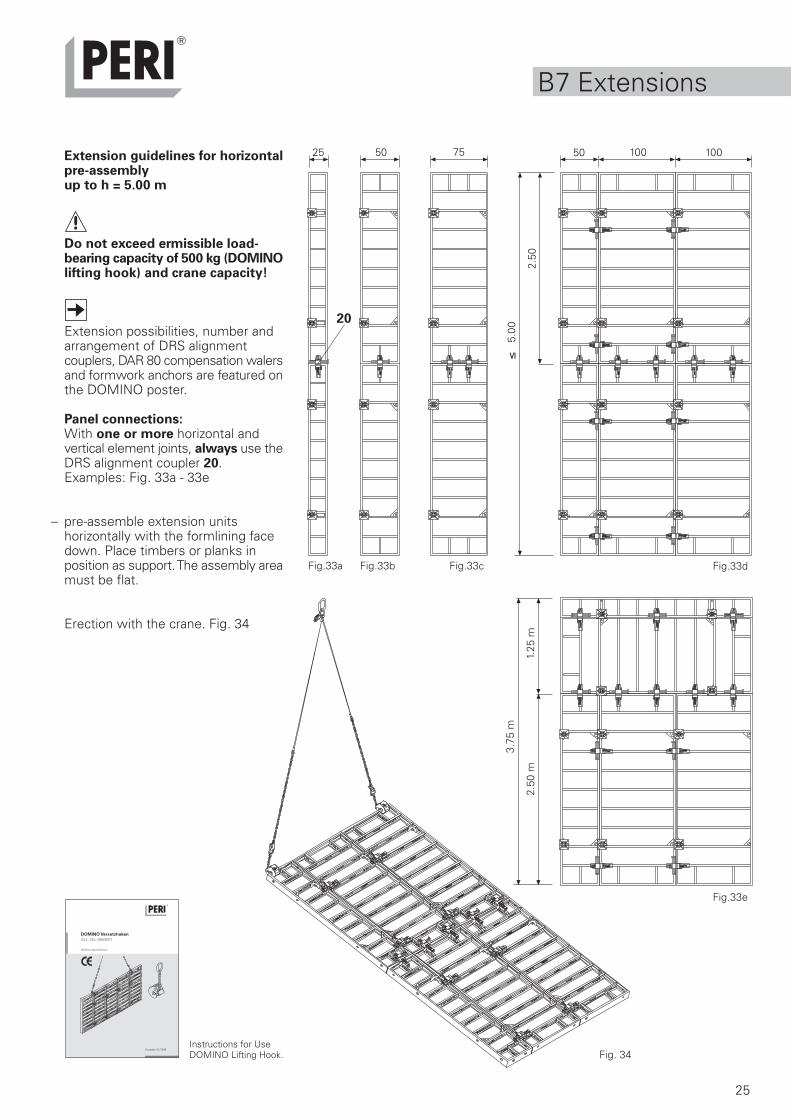
Extension guidelines for horizontalpre-assemblyup to h = 5.00 m
Do not exceed ermissible load-bearing capacity of 500 kg (DOMINOlifting hook) and crane capacity!
Extension possibilities, number andarrangement of DRS alignmentcouplers, DAR 80 compensation walersand formwork anchors are featured onthe DOMINO poster.
Panel connections:With one or more horizontal andvertical element joints, always use theDRS alignment coupler 20.Examples: Fig. 33a - 33e
– pre-assemble extension unitshorizontally with the formlining facedown. Place timbers or planks inposition as support. The assembly areamust be flat.
Erection with the crane. Fig. 34
Fig.33c
Fig. 34
Fig.33bFig.33a
7550 50 100 100
3.75
m
1.25
m2.
50 m
Fig.33d
25
Fig.33e
5.00
2.50
Instructions for UseDOMINO Lifting Hook.
26
85
8685.1
85.2
85
86
B8 Foundations
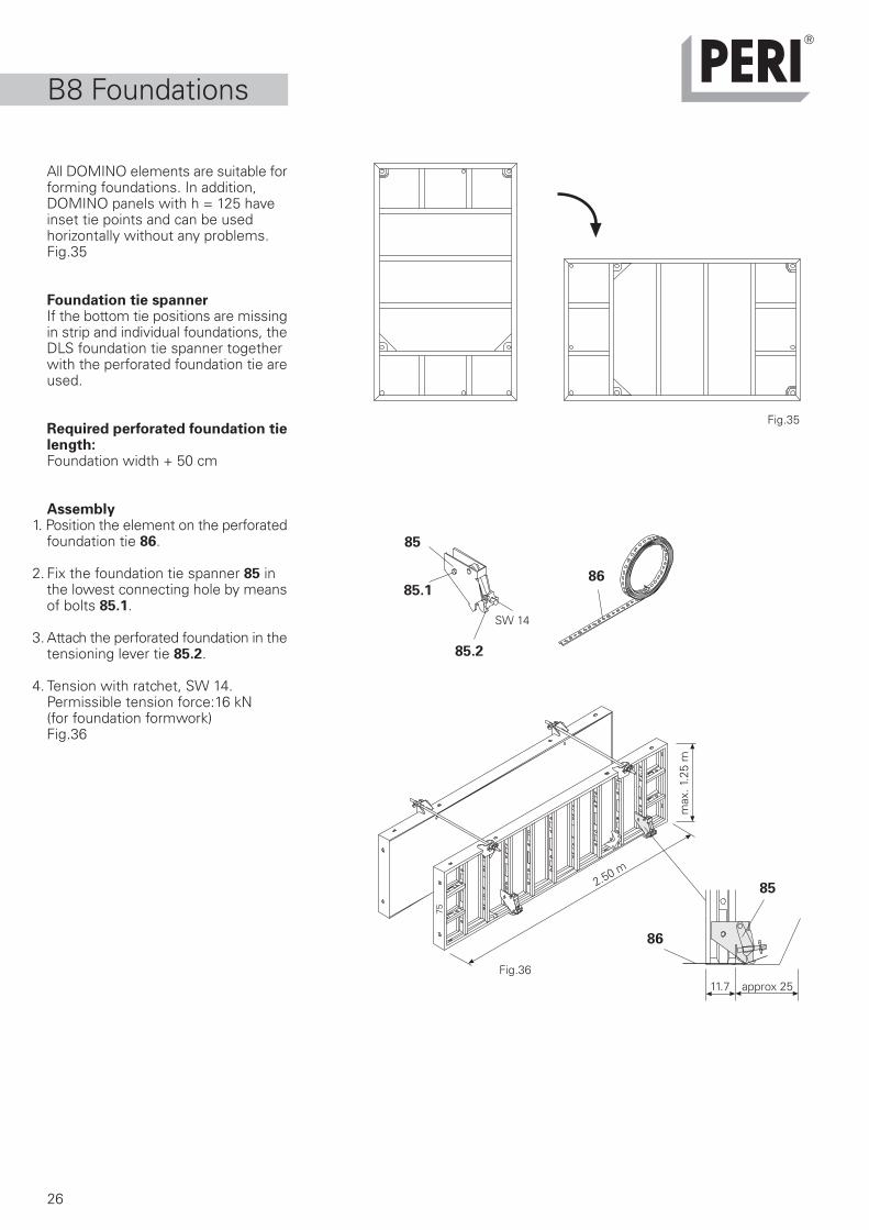
All DOMINO elements are suitable forforming foundations. In addition,DOMINO panels with h = 125 haveinset tie points and can be usedhorizontally without any problems.Fig.35
Foundation tie spannerIf the bottom tie positions are missingin strip and individual foundations, theDLS foundation tie spanner togetherwith the perforated foundation tie areused.
Required perforated foundation tielength:Foundation width + 50 cm
Assembly1. Position the element on the perforated
foundation tie 86.
2. Fix the foundation tie spanner 85 inthe lowest connecting hole by meansof bolts 85.1.
3. Attach the perforated foundation in thetensioning lever tie 85.2.
4. Tension with ratchet, SW 14.Permissible tension force:16 kN(for foundation formwork)Fig.36
Fig.35
2.50 m
max
. 1.2
5 m
75
Fig.36
SW 14
approx 2511.7
27
B9 DOMINO Alu
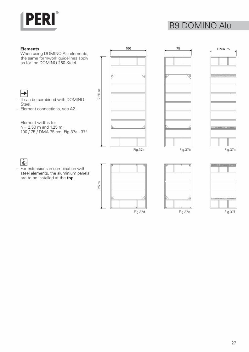
ElementsWhen using DOMINO Alu elements,the same formwork guidelines applyas for the DOMINO 250 Steel.
– It can be combined with DOMINOSteel.
– Element connections, see A2.
Element widths forh = 2.50 m and 1.25 m:100 / 75 / DMA 75 cm, Fig.37a - 37f
– For extensions in combination withsteel elements, the aluminium panelsare to be installed at the top.
Fig.37a
75
2.50
m
DMA 75
1.25
m
Fig.37b Fig.37c
Fig.37fFig.37eFig.37d
100
28
75100 50 7525 DGE DAW DWD
275
125
75
S)S)S) A)
S) S) A)
S) A)
DPA
S) S)
S) A) N)
S) A) N) A A A H
S) N)
A A A H
A A AS)S)S)S)
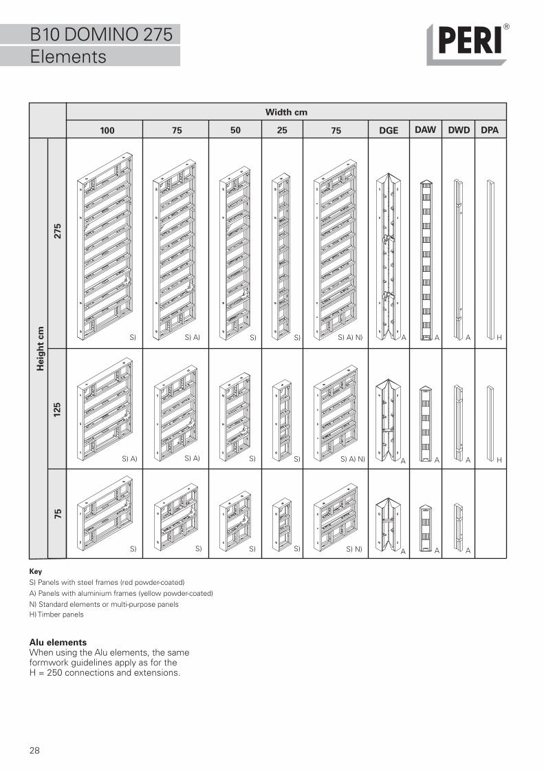
B10 DOMINO 275Elements
Key
S) Panels with steel frames (red powder-coated)A) Panels with aluminium frames (yellow powder-coated)N) Standard elements or multi-purpose panelsH) Timber panels
Alu elementsWhen using the Alu elements, the sameformwork guidelines apply as for theH = 250 connections and extensions.
Heig
ht
cm
Width cm
29
20
20
20
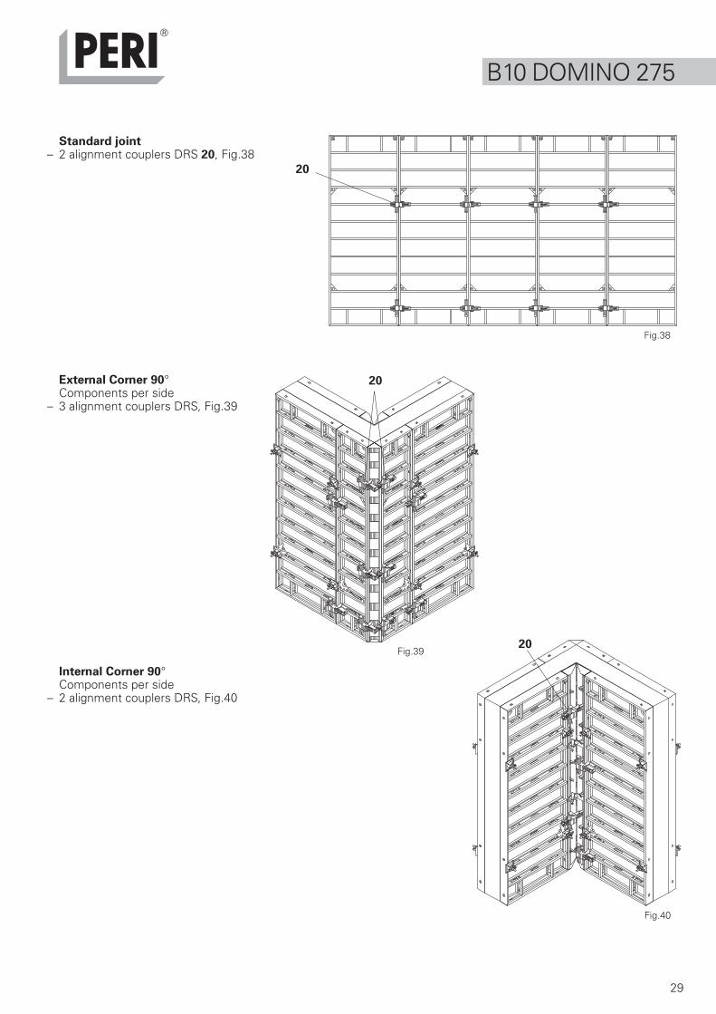
B10 DOMINO 275
Standard joint– 2 alignment couplers DRS 20, Fig.38
External Corner 90°Components per side
– 3 alignment couplers DRS, Fig.39
Internal Corner 90°Components per side
– 2 alignment couplers DRS, Fig.40
Fig.38
Fig.39
Fig.40

30
23
13.1
13.1
24
25
55
B10 DOMINO 275
Stopend formwork with timber andplywood fillersFor wall thicknesses up to max. 36 cmConnecting parts:
– compensation waler DAR 80 24(3x for h = 275)
– stopend tie DSA 25 withwingnut pivot plate (3x)
– top tie bracket DAH 55 with framespannerFig.43
Fig.42
Fig.41
Internal articulated cornersComponents per side
– 4 alignment couplers DRSFor 135° corners, in addition to:
– 2 positioning pins 135° 13.1 inside,Fig.41
External articulated cornersComponents per side
– 5 alignment couplers DRS– 2 compensation walers DAR 80 23
For 135° corners, in addition to:– 2 positioning pins 135° 13.1 outside,
Fig.42
min 75°max 165°
Fig.43
56.1 MTF
AT56
57
31
57
56.1
56
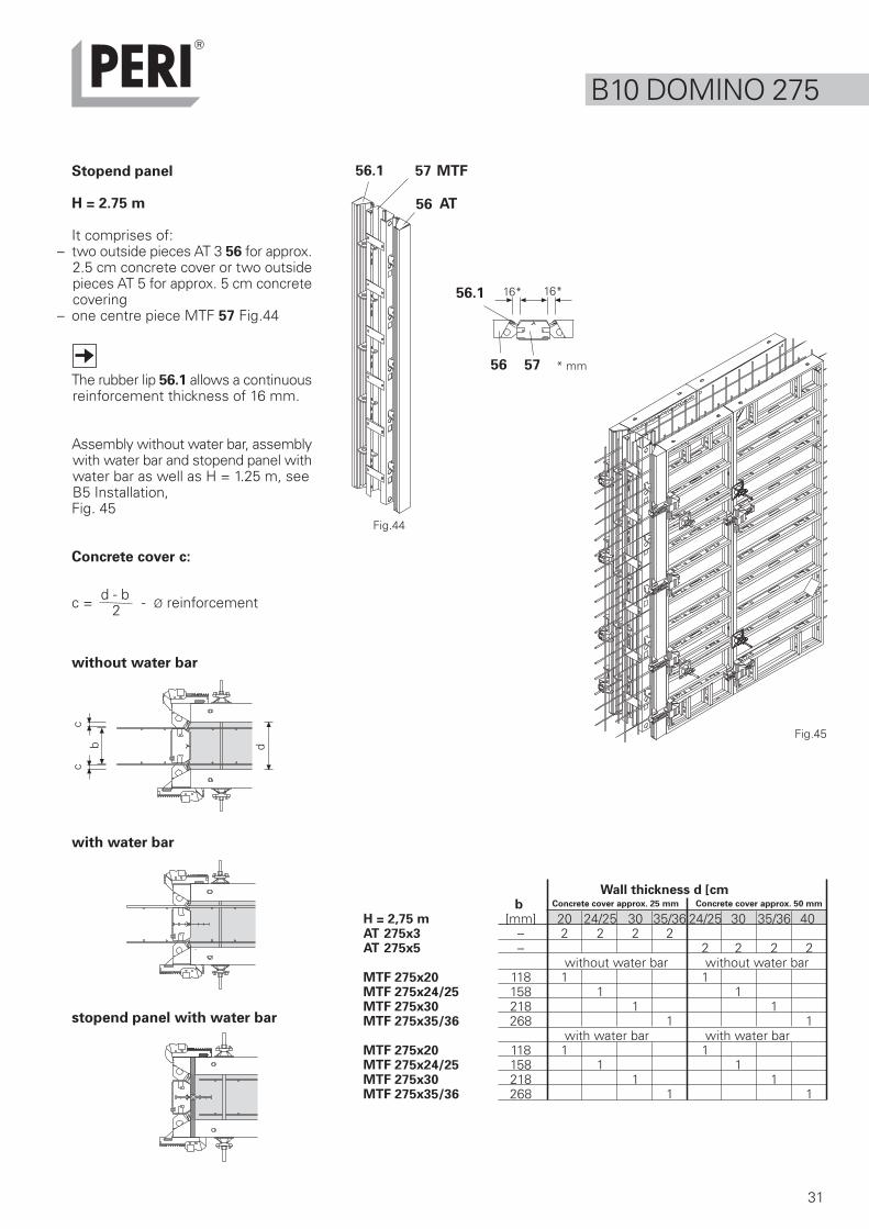
Stopend panel
H = 2.75 m
It comprises of:– two outside pieces AT 3 56 for approx.
2.5 cm concrete cover or two outsidepieces AT 5 for approx. 5 cm concretecovering
– one centre piece MTF 57 Fig.44
The rubber lip 56.1 allows a continuousreinforcement thickness of 16 mm.
Assembly without water bar, assemblywith water bar and stopend panel withwater bar as well as H = 1.25 m, seeB5 Installation,Fig. 45
Concrete cover c:
Fig.44
Fig.45
dbc
c = d - b - Ø reinforcement2
* mm
16* 16*
Wall thickness d [cm b Concrete cover approx. 25 mm Concrete cover approx. 50 mm
H = 2,75 m [mm] 20 24/25 30 35/36 24/25 30 35/36 40AT 275x3 – 2 2 2 2AT 275x5 – 2 2 2 2
without water bar without water barMTF 275x20 118 1 1MTF 275x24/25 158 1 1MTF 275x30 218 1 1MTF 275x35/36 268 1 1
with water bar with water barMTF 275x20 118 1 1MTF 275x24/25 158 1 1MTF 275x30 218 1 1MTF 275x35/36 268 1 1
B10 DOMINO 275
without water bar
with water bar
stopend panel with water bar
c
32
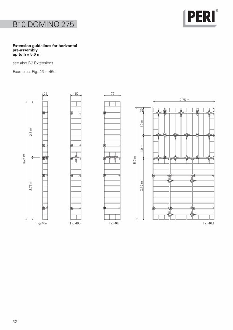
Extension guidelines for horizontalpre-assemblyup to h = 5.0 m
see also B7 Extensions
Examples: Fig. 46a - 46d
Fig.46a Fig.46dFig.46b Fig.46c
B10 DOMINO 2755.
25 m
2.75
m2.
5 m
5.0
m
2.75
m1.
0 m
1.0
m
75
2.75 m
5025
25

33
34
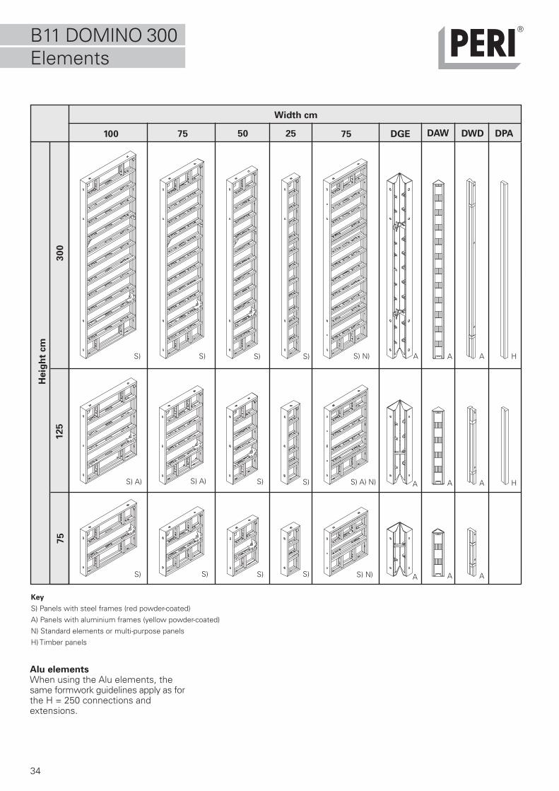
B11 DOMINO 300Elements
Key
S) Panels with steel frames (red powder-coated)A) Panels with aluminium frames (yellow powder-coated)N) Standard elements or multi-purpose panelsH) Timber panels
75100 50 7525 DGE DAW DWD
30
0125
75
Heig
ht
cm
S)S)S) A)
S) S)
S) A)
DPA
S) S)
S) A) N)
S) N) A A A H
S) N)
A A A H
A A AS)S)S)S)
Alu elementsWhen using the Alu elements, thesame formwork guidelines apply as forthe H = 250 connections andextensions.
Width cm
35
20
20
B11 DOMINO 300
Standard joint– 3 alignment couplers DRS 20, Fig.47
External Corner 90°Components per side
– 3 alignment couplers DRS, Fig.48
Internal Corner 90°Components per side
– 3 alignment couplers DRS, Fig.49
Fig.47
Fig.48
Fig.49
36
23
13.1
13.1
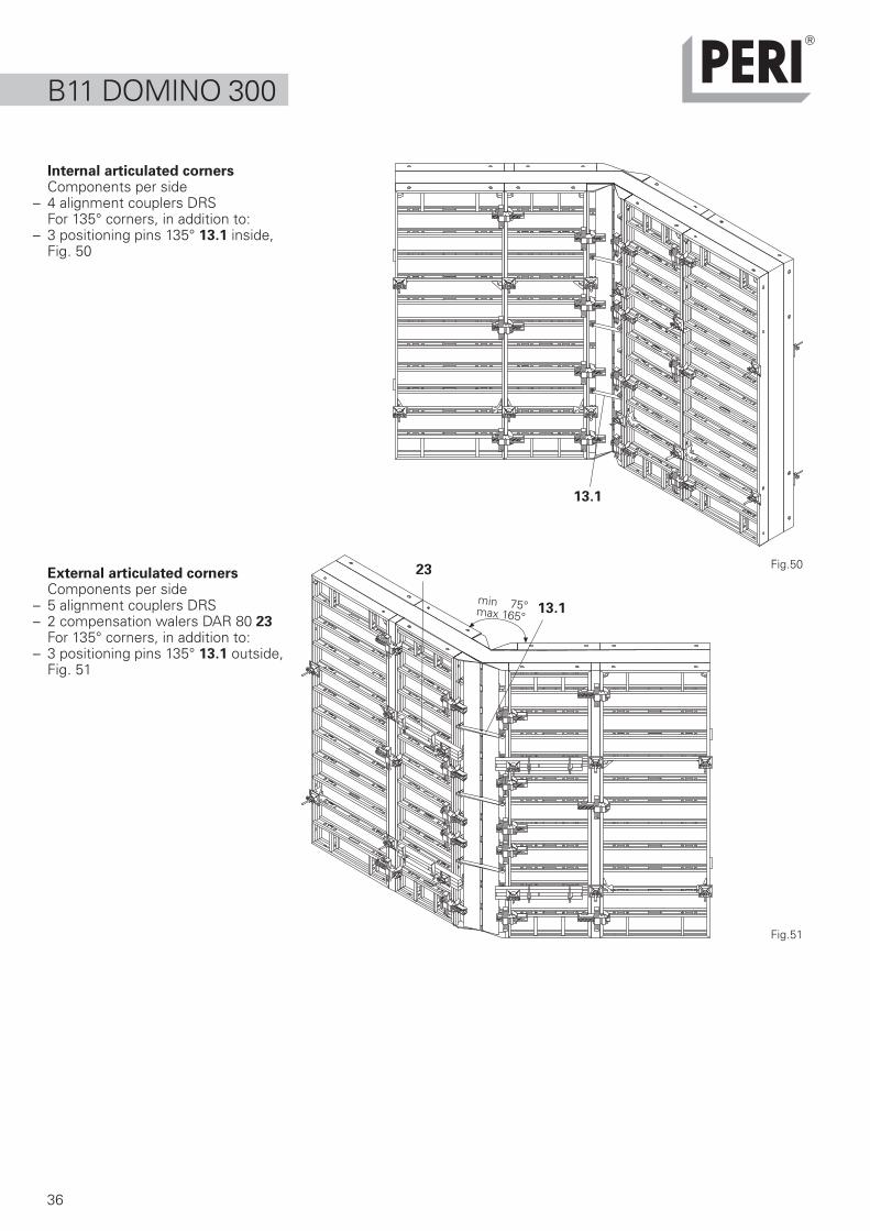
Internal articulated cornersComponents per side
– 4 alignment couplers DRSFor 135° corners, in addition to:
– 3 positioning pins 135° 13.1 inside,Fig. 50
External articulated cornersComponents per side
– 5 alignment couplers DRS– 2 compensation walers DAR 80 23
For 135° corners, in addition to:– 3 positioning pins 135° 13.1 outside,
Fig. 51
B11 DOMINO 300
Fig.50
min 75°max 165°
Fig.51
37
24
25
55
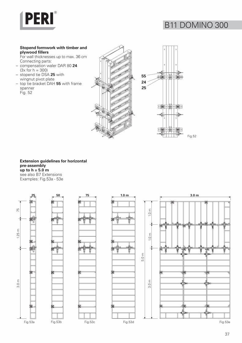
Extension guidelines for horizontalpre-assemblyup to h = 5.0 msee also B7 ExtensionsExamples: Fig.53a - 53e
Fig.53eFig.53a Fig.53cFig.53b
B11 DOMINO 300
Fig.53d
Stopend formwork with timber andplywood fillersFor wall thicknesses up to max. 36 cmConnecting parts:
– compensation waler DAR 80 24(3x for h = 300)
– stopend tie DSA 25 withwingnut pivot plate
– top tie bracket DAH 55 with framespannerFig. 52
Fig.52
5.0
m
3.0
m1.
0 m
1.0
m
3.0 m1.0 m7550
3.0
m1.
25 m
75
25
38
What needs to be done?
Maintenance tips1. Spray formwork on all sides before first use with
a release agent e.g. PERI BIO Clean.
2. Spray formlining every time after striking with PERIBio Clean, then clean.
3. For longer storage periods, e.g. bad weather, storeformwork materials in clean condition and sprayed.
4. Spray (grease if necessary) all moving parts regularlywith a release agent.
5. Transport elements with suitable, as well as safe,transportation and lifting gear.
6. Ensure elements and accessories are properlystored.
7. Do not throw or drop accessories.
8. Never use unnecessary force during assemblyand dismantling.
Cleaning tips
Ensure elements are in a secure position duringcleaning!Cleaning of elements to the crane (without contactto the ground) is not allowed!Remove concrete surplus!
1. Immediately after concreting, spray the rear sideof the formwork with water.
2. After striking has taken place, spray formwork allover with PERI Bio Clean.
3. Remove nails, battens etc. from the plywood beforeany mechanical cleaning.
4. Mechanically clean the elements using suitableequipment e.g. scraper.
5. Brush clean the elements after mechanical cleaning.Remove dust and loosened concrete surplus.
6. After shuttering, element may require sprayingagain.
Why?
Provides good protection against sticking andcorrosion before first dirt accumulation. Preventscomplete moistening with a release agent.
Helps to remove concrete surplus and makes cleaningeasier. Removing by force or scraping off is notnecessary. Formlining and paintwork remain intact.
The frame is protected against corrosion andweathering.
Removes rust, prevents corrosion and keeps partsin good working order.
Avoids damage through improper transportation.
Prevents damage to the element frame andaccessories. Damage to the formlining throughindentations is avoided.
Maintains the functionality of the parts.
Maintains the functionality of the parts.
Concrete has not yet hardened and can easily beremoved. This reduces the amount of cleaningrequired.
Penetrates the concrete surplus, breaks it up andmakes subsequent mechanical cleaning much easier.
Unnecessary enlargement of nail holes and damageto the formlining is avoided. No damage to cleaningequipment.
Formlining surface is clean for the next use.
C1 Maintenanceand cleaning
39
DOMINO VersetzhakenArt.-Nr. 066091
Ausgabe 01/1996
Bedienungsanleitung
C2 Repairs
Smaller repairs can be carried out onthe construction site, e.g. with repairveneer and cross-pieces
Bigger repairs, e.g. change offormlining, are to be done by PERI orat a suitable work station.
Spare parts and tools are available fromthe PERI product range.
C3 Storage andTransport
When using load-carryingequipment, the instructions for usemust be followed at all times:
– DOMINO lifting hook
– Lifting gear
– Pallets and stacking devices
Instructions for UseDOMINO Lifting Hook.
160 120 16056 56
117
50 125 125 125 125
160 16056 56
125 125 125 125
160 100
160
250
5656
125
120
ø 2040
2500
250
1000
250 250
250
250
750
250 250
500
250 250
250
250
530
1440
530
250
250
250
250
250
2500
500
1440
530
750
250 250
250
250
250
250
250
500
250
530
ø 20
41 34
30
30
160 120 16056 56
117
50 125 125 125 125
x
40
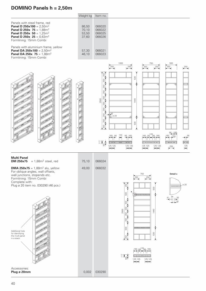
Panels with steel frame, redPanel D 250x100 = 2,50m2 86,50 066020Panel D 250x 75 = 1,88m2 70,10 066022Panel D 250x 50 = 1,25m2 53,50 066025Panel D 250x 25 = 0,63m2 37,60 066026Formlining: 15mm Combi
Panels with aluminium frame, yellowPanel DA 250x100 = 2,50m2 57,30 066021Panel DA 250x 75 = 1,88m2 46,10 066023Formlining: 15mm Combi
Multi PanelDM 250x75 = 1,88m2 steel, red 75,10 066024
DMA 250x75 = 1,88m2 alu, yellow 49,00 066032For oblique angles, wall offsets,wall junctions, stopends etc.Formlining: 15mm CombiComplete with:Plug ø 20 item no. 030290 (46 pcs.)
Accessories:Plug ø 20mm 0,002 030290
Weight kg Item no.
Additional holefor identifyingthe multi panelin a stack.
Detail x
DOMINO Panels h = 2,50m
470135°
320135°90
°
120
12012
0 60
492
2500
240
250
250
530
1440
530
203
250
250
260
298
250
250
246
x ø 20
30 40
75°
25011
7
250
117
117
250
250
250
2500
250
250
250
250
250
250
250
430
117
527
2500
25
53343
040
50
2490
93
36 50
117
27
100
280
530
355
2500
355
40
41
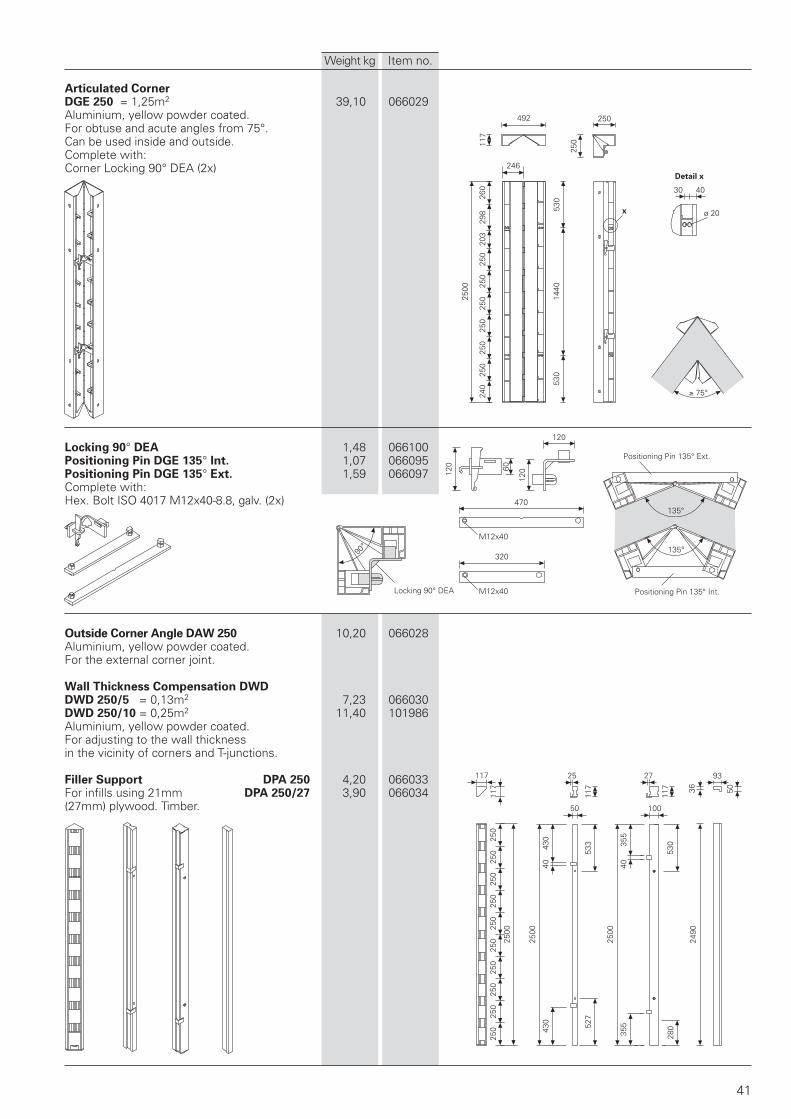
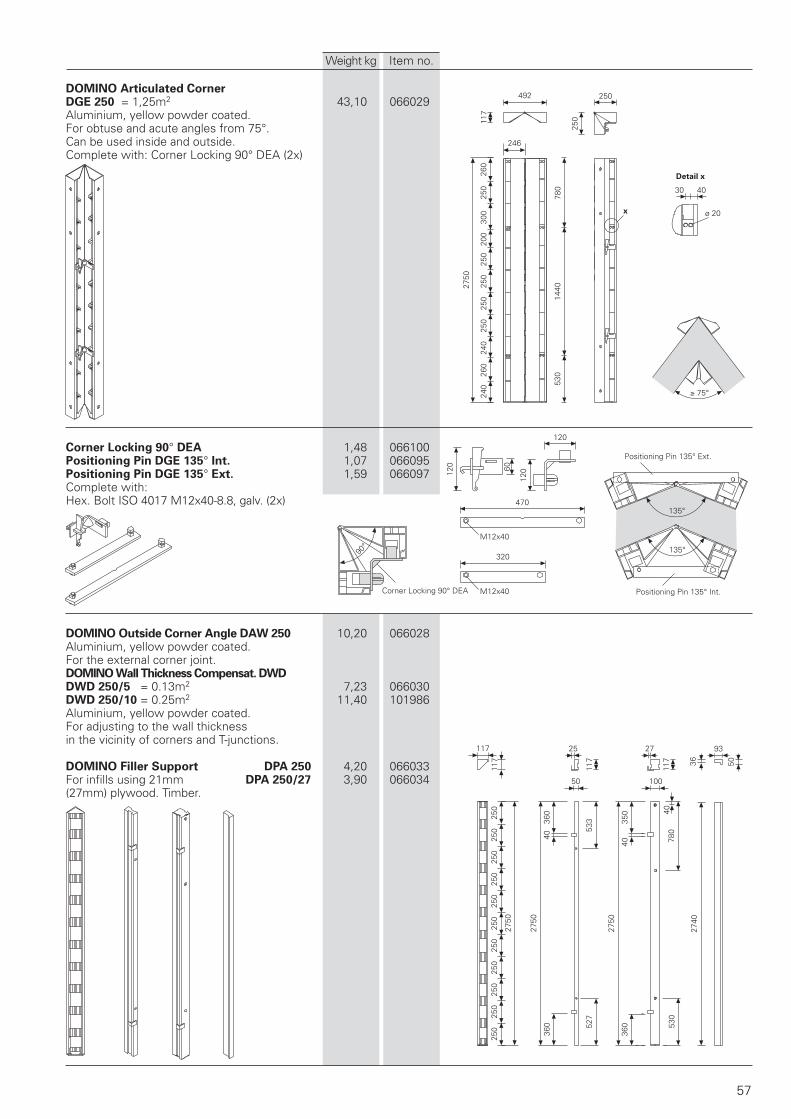
Articulated CornerDGE 250 = 1,25m2 39,10 066029Aluminium, yellow powder coated.For obtuse and acute angles from 75°.Can be used inside and outside.Complete with:Corner Locking 90° DEA (2x)
Locking 90° DEA 1,48 066100Positioning Pin DGE 135° Int. 1,07 066095Positioning Pin DGE 135° Ext. 1,59 066097Complete with:Hex. Bolt ISO 4017 M12x40-8.8, galv. (2x)
Outside Corner Angle DAW 250 10,20 066028Aluminium, yellow powder coated.For the external corner joint.
Wall Thickness Compensation DWDDWD 250/5 = 0,13m2 7,23 066030DWD 250/10 = 0,25m2 11,40 101986Aluminium, yellow powder coated.For adjusting to the wall thicknessin the vicinity of corners and T-junctions.
Filler Support DPA 250 4,20 066033For infills using 21mm DPA 250/27 3,90 066034(27mm) plywood. Timber.
Weight kg Item no.
Locking 90° DEA M12x40
M12x40
Positioning Pin 135° Ext.
Positioning Pin 135° Int.
Detail x
1250
250
240
930
40
1000
250 250
250
250
ø 2040
160 120 16056 56
117
50 125 125 125 125
160 16056 56
125 125 125 125
160 100
160
250
5656
125
750
250 250
500
250 250
250
250
120
40 280 40
280
930
40
1250
500
250
280
930
40
750
250 250
250
250
ø 20
41 34
30
30
160 120 16056 56
117
50 125 125 125 125
x
42
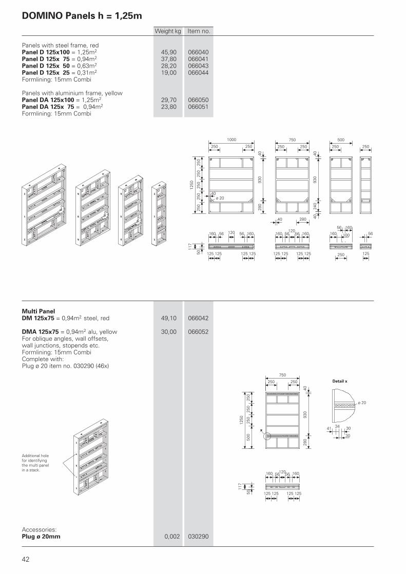
Panels with steel frame, redPanel D 125x100 = 1,25m2 45,90 066040Panel D 125x 75 = 0,94m2 37,80 066041Panel D 125x 50 = 0,63m2 28,20 066043Panel D 125x 25 = 0,31m2 19,00 066044Formlining: 15mm Combi
Panels with aluminium frame, yellowPanel DA 125x100 = 1,25m2 29,70 066050Panel DA 125x 75 = 0,94m2 23,80 066051Formlining: 15mm Combi
Multi PanelDM 125x75 = 0,94m2 steel, red 49,10 066042
DMA 125x75 = 0,94m2 alu, yellow 30,00 066052For oblique angles, wall offsets,wall junctions, stopends etc.Formlining: 15mm CombiComplete with:Plug ø 20 item no. 030290 (46x)
Accessories:Plug ø 20mm 0,002 030290
Weight kg Item no.
Additional holefor identifyingthe multi panelin a stack.
Detail x
DOMINO Panels h = 1,25m
90°
470135°
320135°
120
12012
0 60
1250
253
260
238
280
930
40
250
250
246
x
75°
ø 20
30 40
492
25011
7
250
117
117
250
250
250
1250
250
250
117
25
175
40
50
277
1250
175
43
1240
93
36 50
117
27
100
4328
0
355
40
1250
355
43
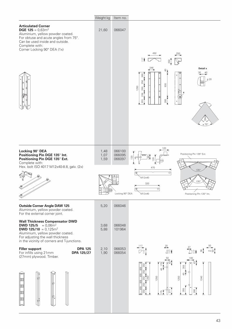
Articulated CornerDGE 125 = 0,63m2 21,60 066047Aluminium, yellow powder coated.For obtuse and acute angles from 75°.Can be used inside and outside.Complete with:Corner Locking 90° DEA (1x)
Locking 90° DEA 1,48 066100Positioning Pin DGE 135° Int. 1,07 066095Positioning Pin DGE 135° Ext. 1,59 066097Complete with:Hex. bolt ISO 4017 M12x40-8.8, galv. (2x)
Outside Corner Angle DAW 125 5,20 066046Aluminium, yellow powder coated.For the external corner joint.
Wall Thickness Compensator DWDDWD 125/5 = 0,06m2 3,68 066048DWD 125/10 = 0,125m2 5,88 101964Aluminium, yellow powder coated.For adjusting the wall thicknessin the vicinity of corners and T-junctions.
Filler support DPA 125 2,10 066053For infills using 21mm DPA 125/27 1,90 066054(27mm) plywood. Timber.
Locking 90° DEA M12x40
M12x40
Positioning Pin 135° Int.
Positioning Pin 135° Ext.
Detail x
Weight kg Item no.
250
250
250
750
750
250
280
430
40
1000
250 250
250
250
ø 2040
160 120 16056 56
117
50 125 125 125 125
160 120 16056 56
125 125 125 125
160 100
160
250
56
56
125
750
250 250
500
250 250
750
500
250
280
430
40
750
250 250
ø 20
41 34
30
30
160 120 16056 56
117
50 125 125 125 125
117
117
117
25
50
4327
7
175
175
40
750
x
250
250
ø 20
30 40
750
253
280
430
40
238
260
246
x
75°
492
117
44
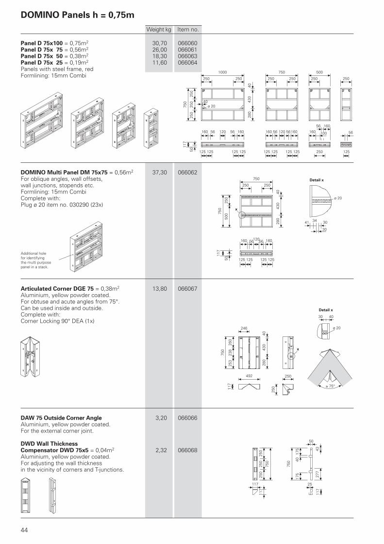
Panel D 75x100 = 0,75m2 30,70 066060Panel D 75x 75 = 0,56m2 26,00 066061Panel D 75x 50 = 0,38m2 18,30 066063Panel D 75x 25 = 0,19m2 11,60 066064Panels with steel frame, redFormlining: 15mm Combi
DOMINO Multi Panel DM 75x75 = 0,56m2 37,30 066062For oblique angles, wall offsets,wall junctions, stopends etc.Formlining: 15mm CombiComplete with:Plug ø 20 item no. 030290 (23x)
Articulated Corner DGE 75 = 0,38m2 13,80 066067Aluminium, yellow powder coated.For obtuse and acute angles from 75°.Can be used inside and outside.Complete with:Corner Locking 90° DEA (1x)
DAW 75 Outside Corner Angle 3,20 066066Aluminium, yellow powder coated.For the external corner joint.
DWD Wall ThicknessCompensator DWD 75x5 = 0,04m2 2,32 066068Aluminium, yellow powder coated.For adjusting the wall thicknessin the vicinity of corners and T-junctions.
Detail x
Weight kg Item no.
Detail x
Additional holefor identifyingthe multi purposepanel in a stack.
DOMINO Panels h = 0,75m
d
b
cc
cc
b
d
cc
b
d
45
Stopend Panel DOMINO H = 2,50m b d[mm] [mm]
Outside piece AT 250x 3 15,10 101927 – –AT 250x 5 16,80 108855 – –
Center piece w. waterst. MTF 250x20 27,40 101928 118 200MTF 250x24/25 31,40 101929 158 240/250MTF 250x30 34,80 101930 218 300MTF 250x35/36 40,00 101931 268 350/360
1. With waterstop
2. Without waterstop
Concrete cover c: c = d – b – ø Rebar2
Stopend Panel DOMINOH = 1,25m b d
[mm] [mm]Outside piece AT 125x 3 7,60 101934 – –
AT 125x 5 8,45 108856 – –Center piece w. waterst. MTF 125x20 14,80 101935 118 200
MTF 125x24/25 15,30 101936 158 240/250MTF 125x30 17,60 101937 218 300MTF 125x35/36 19,40 101940 268 350/360
3. For expansion joint
Concrete cover c: c = d – b – ø Rebar2
Weight kg Item no.
AT
MTF
MTF
AT
DOMINO Stopend Panel
52 61 241
288
132
5824
790
30
32
30
60
165
60
110
195
505
80137
30°
134
140
121
50
25
46
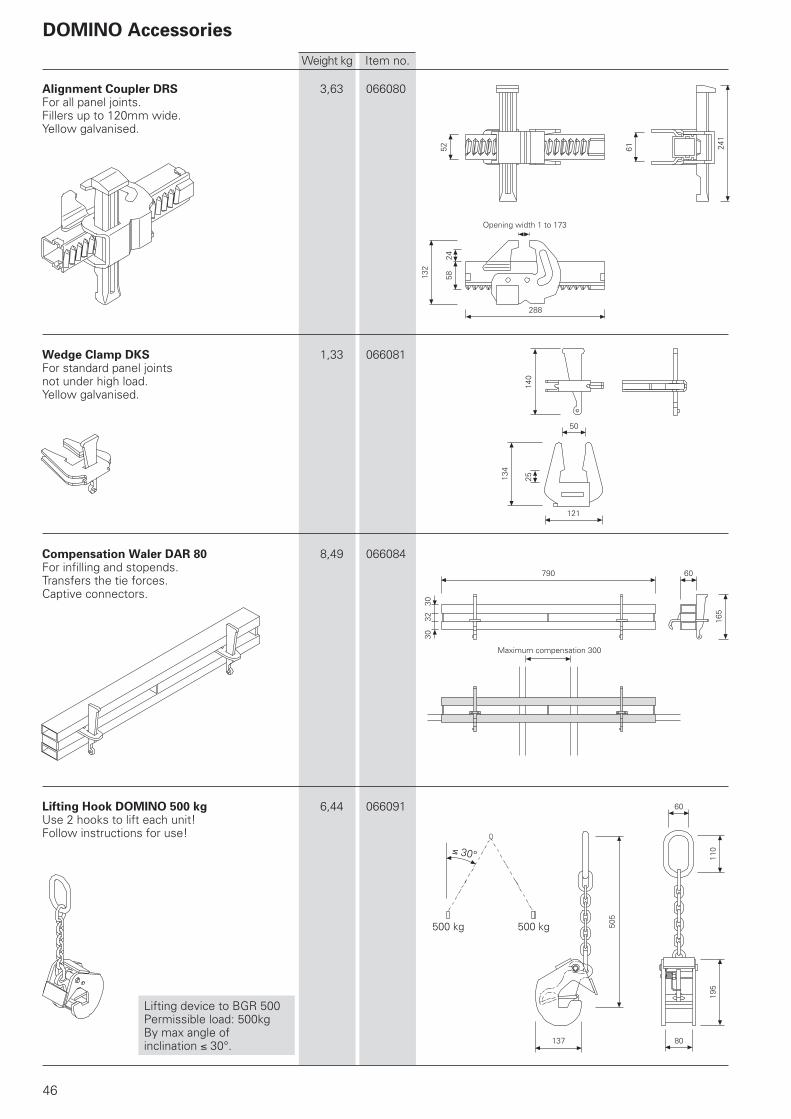
Alignment Coupler DRS 3,63 066080For all panel joints.Fillers up to 120mm wide.Yellow galvanised.
Wedge Clamp DKS 1,33 066081For standard panel jointsnot under high load.Yellow galvanised.
Compensation Waler DAR 80 8,49 066084For infilling and stopends.Transfers the tie forces.Captive connectors.
Lifting Hook DOMINO 500 kg 6,44 066091Use 2 hooks to lift each unit!Follow instructions for use!
Lifting device to BGR 500Permissible load: 500kgBy max angle ofinclination 30°.
Maximum compensation 300
Opening width 1 to 173
Weight kg Item no.
500 kg 500 kg
DOMINO Accessories
850
40
600
42
30
35
120
560
1050
1300
39
1020
1645
550
739
1230 400
322
160
135
261
21330
47
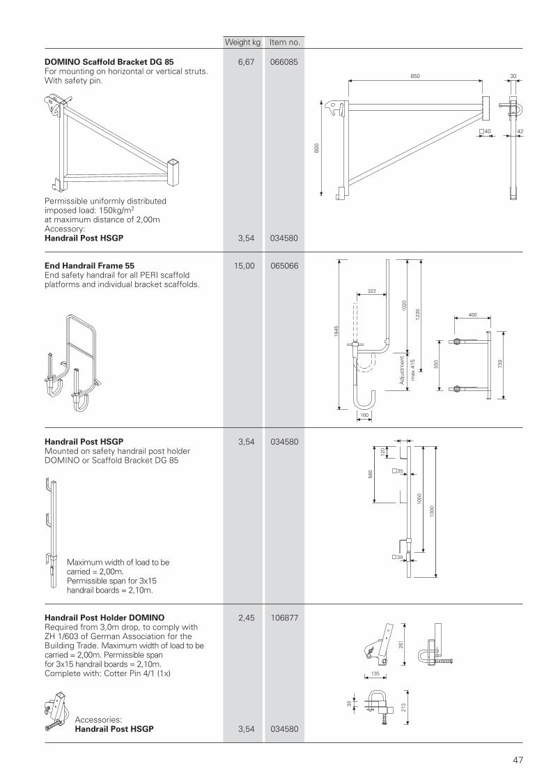
DOMINO Scaffold Bracket DG 85 6,67 066085For mounting on horizontal or vertical struts.With safety pin.
Permissible uniformly distributedimposed load: 150kg/m2
at maximum distance of 2,00mAccessory:Handrail Post HSGP 3,54 034580
End Handrail Frame 55 15,00 065066End safety handrail for all PERI scaffoldplatforms and individual bracket scaffolds.
Handrail Post HSGP 3,54 034580Mounted on safety handrail post holderDOMINO or Scaffold Bracket DG 85
Maximum width of load to becarried = 2,00m.Permissible span for 3x15handrail boards = 2,10m.
Handrail Post Holder DOMINO 2,45 106877Required from 3,0m drop, to comply withZH 1/603 of German Association for theBuilding Trade. Maximum width of load to becarried = 2,00m. Permissible spanfor 3x15 handrail boards = 2,10m.Complete with: Cotter Pin 4/1 (1x)
Accessories:Handrail Post HSGP 3,54 034580
Weight kg Item no.
Adj
ustm
ent
max
415
90
134
53
95
443
502
58
20
30102
68
120
82
68
14
ø 21
ø 23
48
Weight kg Item no.
Female threadDW15
Thread DW15
Thread DW15
ø 16x42FS 4/1
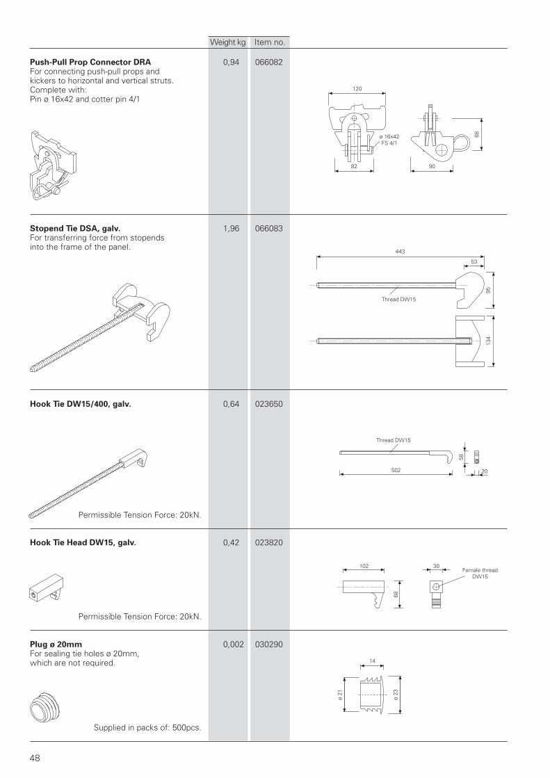
Push-Pull Prop Connector DRA 0,94 066082For connecting push-pull props andkickers to horizontal and vertical struts.Complete with:Pin ø 16x42 and cotter pin 4/1
Stopend Tie DSA, galv. 1,96 066083For transferring force from stopendsinto the frame of the panel.
Hook Tie DW15/400, galv. 0,64 023650
Permissible Tension Force: 20kN.
Hook Tie Head DW15, galv. 0,42 023820
Permissible Tension Force: 20kN.
Plug ø 20mm 0,002 030290For sealing tie holes ø 20mm,which are not required.
Supplied in packs of: 500pcs.

167
34
90
20
40
100
38
26
88
100
ø 20
1150
146
150
100
152
22
50
15
49
Foundation Tie Clamp DOMINO DLS 2,89 066090For tying foundation formwork incombination with perforated foundation tie.
Perforated Foundation Tie, 25m roll 16,90 023020For use with foundation tieclamp DOMINO DLS.
Permissible Tension Force: 12,9kN.
Top Tie Bracket DAH, galv. 1,10 066086For tying at any position alongthe frame, particularly for foundations.
Stacking Device DOMINO, galv. 8,44 066094For stacking and lifting 2 to 8 DOMINOpanels of each size. Allows the panels tobe moved with the crane or fork-lift truck.4 devices needed for each stack.Follow instructions for use!
Lifting device to BGR 500 Permissible load: 250kg/device or 1000kg per stack.
2nd to 8th panelwith formliningfacing up
1st panel with formliningfacingdown
Clamping travel 55mm
SW 14
Weight kg Item no.
55
ø 30
ø 20
50
50
ø 30
24
24
141
141
2500
50
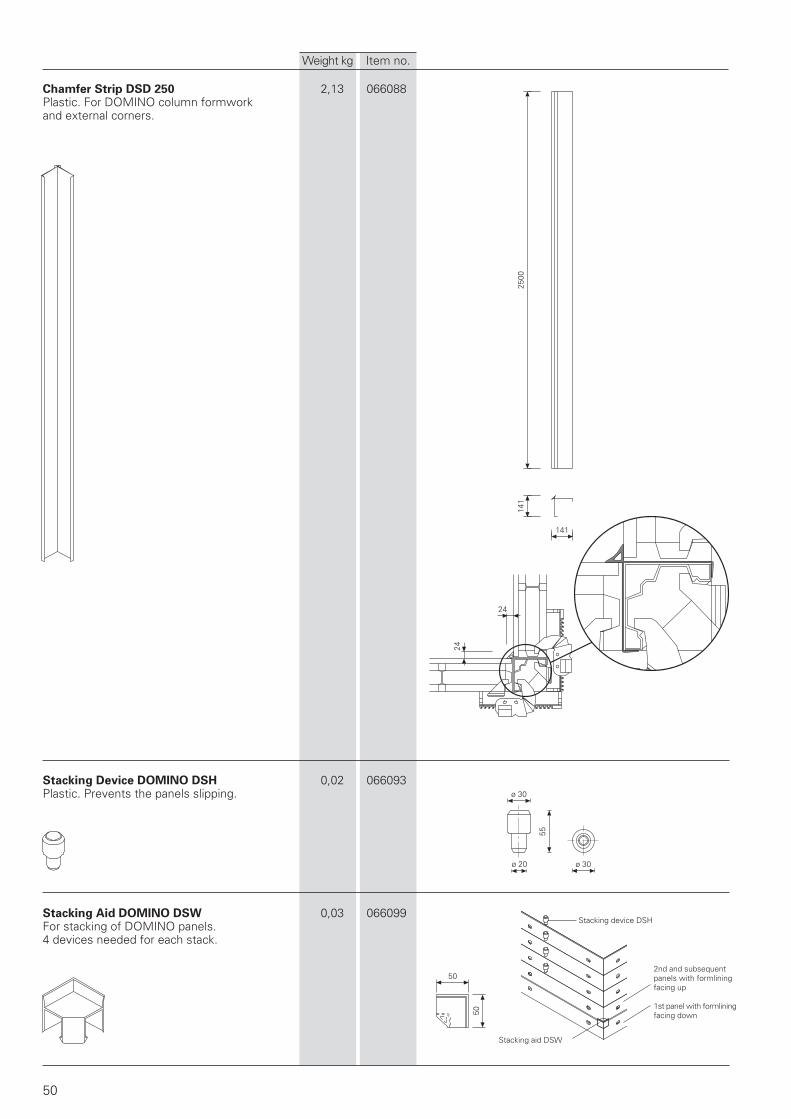
Chamfer Strip DSD 250 2,13 066088Plastic. For DOMINO column formworkand external corners.
Stacking Device DOMINO DSH 0,02 066093Plastic. Prevents the panels slipping.
Stacking Aid DOMINO DSW 0,03 066099For stacking of DOMINO panels.4 devices needed for each stack.
Stacking aid DSW
2nd and subsequentpanels with formliningfacing up
1st panel with formliningfacing down
Stacking device DSH
Weight kg Item no.

51
52
71
RSS I 1915RSS II 2775
10
40ø 16
36
15
ø 16
ø 70
980
134
40
ø 38
10
971
1036
ø 7
0
ø 16
ø 16
20
130
60
67
80
30 12150
100
10
ø 21 ø 11
40 65 20
ø 11
100
10
ø 21
70 30
ø 11
60
65
RS, RSS Push-Pull Props and Accessories
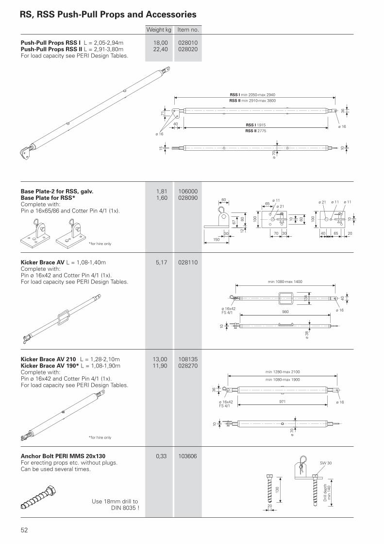
Weight kg Item no.
Push-Pull Props RSS I L = 2,05-2,94m 18,00 028010Push-Pull Props RSS II L = 2,91-3,80m 22,40 028020For load capacity see PERI Design Tables.
Base Plate-2 for RSS, galv. 1,81 106000Base Plate for RSS* 1,60 028090Complete with:Pin ø 16x65/86 and Cotter Pin 4/1 (1x).
*for hire only
Kicker Brace AV L = 1,08-1,40m 5,17 028110Complete with:Pin ø 16x42 and Cotter Pin 4/1 (1x).For load capacity see PERI Design Tables.
Kicker Brace AV 210 L = 1,28-2,10m 13,00 108135Kicker Brace AV 190* L = 1,08-1,90m 11,90 028270Complete with:Pin ø 16x42 and Cotter Pin 4/1 (1x).For load capacity see PERI Design Tables.
*for hire only
Anchor Bolt PERI MMS 20x130 0,33 103606For erecting props etc. without plugs.Can be used several times.
Use 18mm drill toDIN 8035 !
ø 16x42FS 4/1
ø 16x42FS 4/1
SW 30
Dril
l dep
thm
in 1
40
min 1080-max 1400
RSS I min 2050-max 2940RSS II min 2910-max 3800
min 1280-max 2100
min 1080-max 1900
53
ø 83
41 4434
1571
1048
ø 16ø 16
1915
4010
ø 7
0
ø 16
57 4
100ø 16
4812
90
ø 21ø 13ø 21
40 55 30 25
60
150
65
80
60
40 10
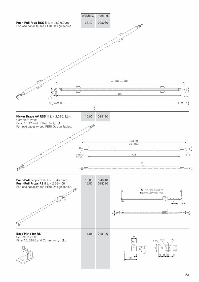
Push-Pull Prop RSS III L = 4,60-6,00m 38,40 028030For load capacity see PERI Design Tables.
Kicker Brace AV RSS III L = 2,03-2,92m 16,90 028120Complete with:Pin ø 16x42 and Cotter Pin 4/1 (1x).For load capacity see PERI Design Tables.
Push-Pull Props RS I L = 1,84-2,94m 13,00 028210Push-Pull Props RS II L = 2,56-4,06m 16,80 028220For load capacity see PERI Design Tables.
Base Plate for RS 1,86 028100Complete with:Pin ø 16x65/86 and Cotter pin 4/1 (1x).
min 4600-max 6000
Weight kg Item no.
min 2030max 2920
ø 16x42FS 4/1
RS I min 1840-max 2940RS II min 2560-max 4060
54
27
120
76
110
ø 9
50
106
50
120
25
15
ø 20
2796
8° 8°
DW 15 ø 34
110
L
ø 25
1096
7413
0
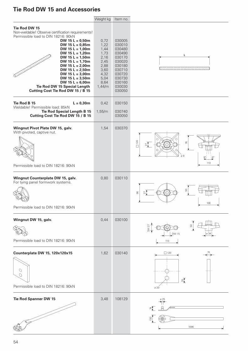
Tie Rod DW 15 and Accessories
Tie Rod DW 15Non-weldable! Observe certification requirements!Permissible load to DIN 18216: 90kN
DW 15 L = 0,50m 0,72 030005DW 15 L = 0,85m 1,22 030010DW 15 L = 1,00m 1,44 030480DW 15 L = 1,20m 1,73 030490DW 15 L = 1,50m 2,16 030170DW 15 L = 1,70m 2,45 030020DW 15 L = 2,00m 2,88 030180DW 15 L = 2,50m 3,60 030710DW 15 L = 3,00m 4,32 030720DW 15 L = 3,50m 5,04 030730DW 15 L = 6,00m 8,64 030160
Tie Rod DW 15 Special Length 1,44/m 030030Cutting Cost Tie Rod DW 15 / B 15 030050
Tie Rod B 15 L = 0,30m 0,42 030150Weldable! Permissible load: 85kN
Tie Rod Special Length B 15 1,55/m 030740Cutting Cost Tie Rod DW 15 / B 15 030050
Wingnut Pivot Plate DW 15, galv. 1,54 030370With pivoted, captive nut.
Permissible load to DIN 18216: 90kN
Wingnut Counterplate DW 15, galv. 0,80 030110For tying panel formwork systems.
Permissible load to DIN 18216: 90kN
Wingnut DW 15, galv. 0,44 030100
Permissible load to DIN 18216: 90kN
Counterplate DW 15, 120x120x15 1,62 030140
Permissible load to DIN 18216: 90kN
Tie Rod Spanner DW 15 3,48 108129
Weight kg Item no.
SW
27
55
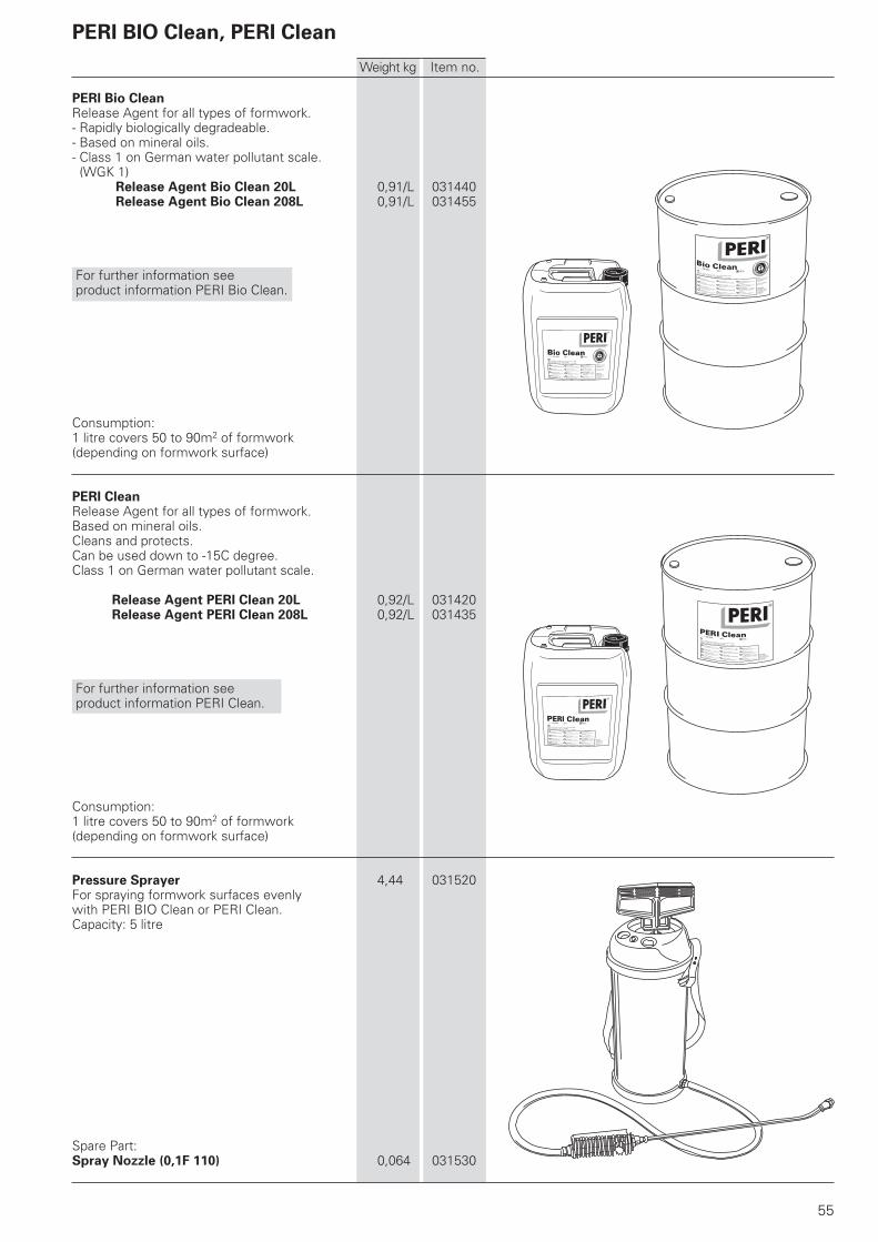
PERI Bio CleanRelease Agent for all types of formwork.- Rapidly biologically degradeable.- Based on mineral oils.- Class 1 on German water pollutant scale. (WGK 1)
Release Agent Bio Clean 20L 0,91/L 031440Release Agent Bio Clean 208L 0,91/L 031455
For further information see product information PERI Bio Clean.
Consumption:1 litre covers 50 to 90m2 of formwork(depending on formwork surface)
PERI CleanRelease Agent for all types of formwork.Based on mineral oils.Cleans and protects.Can be used down to -15C degree.Class 1 on German water pollutant scale.
Release Agent PERI Clean 20L 0,92/L 031420Release Agent PERI Clean 208L 0,92/L 031435
For further information see product information PERI Clean.
Consumption:1 litre covers 50 to 90m2 of formwork(depending on formwork surface)
Pressure Sprayer 4,44 031520For spraying formwork surfaces evenlywith PERI BIO Clean or PERI Clean.Capacity: 5 litre
Spare Part:Spray Nozzle (0,1F 110) 0,064 031530
Weight kg Item no.
PERI BIO Clean, PERI Clean
56
2750
500
1440
740
750
250 250
250
250
250
250
250
500
250
530
ø 20
41 34
30
30
160 120 16056 56
117
50 125 125 125 125
x
160 120 16056 56
117
50 125 125 125 125
160 16056 56
125 125 125 125
160 100
160
250
5656
125
120
2750
250
1000
250 250
250
250
750
250 250
500
250 250
250
250
530
1440
740
250
250
250
250
250
250
40
40
250
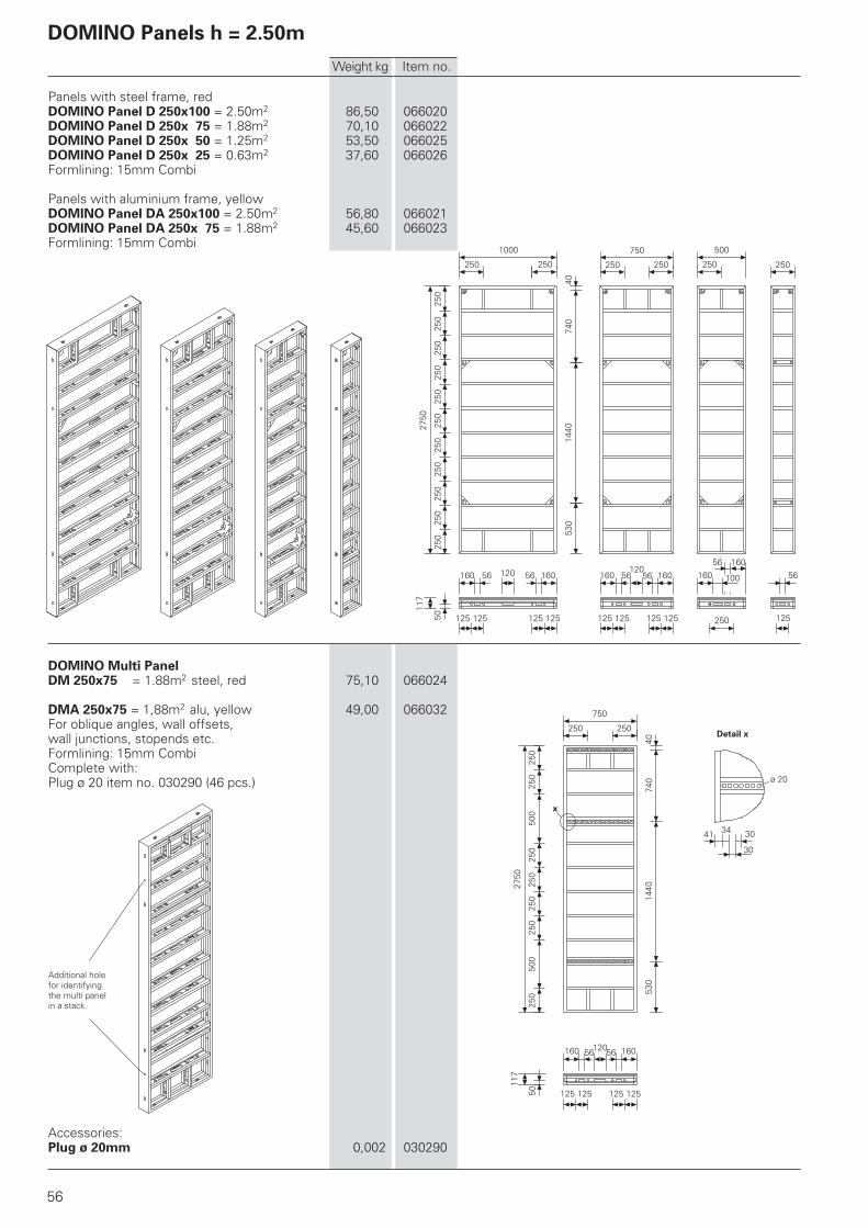
Panels with steel frame, redDOMINO Panel D 250x100 = 2.50m2 86,50 066020DOMINO Panel D 250x 75 = 1.88m2 70,10 066022DOMINO Panel D 250x 50 = 1.25m2 53,50 066025DOMINO Panel D 250x 25 = 0.63m2 37,60 066026Formlining: 15mm Combi
Panels with aluminium frame, yellowDOMINO Panel DA 250x100 = 2.50m2 56,80 066021DOMINO Panel DA 250x 75 = 1.88m2 45,60 066023Formlining: 15mm Combi
DOMINO Multi PanelDM 250x75 = 1.88m2 steel, red 75,10 066024
DMA 250x75 = 1,88m2 alu, yellow 49,00 066032For oblique angles, wall offsets,wall junctions, stopends etc.Formlining: 15mm CombiComplete with:Plug ø 20 item no. 030290 (46 pcs.)
Accessories:Plug ø 20mm 0,002 030290
DOMINO Panels h = 2.50m
Weight kg Item no.
Additional holefor identifyingthe multi panelin a stack.
Detail x
57
470135°
320135°90
°
120
12012
0 60
492
2750
240
250
260
530
1440
780
200
250
250
250
300
240
250
246
x ø 20
30 40
75°
25011
7
250
117
117
250
250
250
2750
250
250
250
250
250
250
250
360
117
527
2750
25
53336
040
50
2740
93
36 50
117
27
100
530
780
360
2750
350
40
260
250 40
DOMINO Articulated CornerDGE 250 = 1,25m2 43,10 066029Aluminium, yellow powder coated.For obtuse and acute angles from 75°.Can be used inside and outside.Complete with: Corner Locking 90° DEA (2x)
Corner Locking 90° DEA 1,48 066100Positioning Pin DGE 135° Int. 1,07 066095Positioning Pin DGE 135° Ext. 1,59 066097Complete with:Hex. Bolt ISO 4017 M12x40-8.8, galv. (2x)
DOMINO Outside Corner Angle DAW 250 10,20 066028Aluminium, yellow powder coated.For the external corner joint.DOMINO Wall Thickness Compensat. DWDDWD 250/5 = 0.13m2 7,23 066030DWD 250/10 = 0.25m2 11,40 101986Aluminium, yellow powder coated.For adjusting to the wall thicknessin the vicinity of corners and T-junctions.
DOMINO Filler Support DPA 250 4,20 066033For infills using 21mm DPA 250/27 3,90 066034(27mm) plywood. Timber.
Weight kg Item no.
Corner Locking 90° DEA M12x40
M12x40
Positioning Pin 135° Ext.
Positioning Pin 135° Int.
Detail x
160 120 16056 56
117
50 125 125 125 125
ø 20
41 34
30
30
3000
750
250 250
500
250
250
250
530
1440
990
500
250
250
250
250
250
40
160 120 16056 56
117
50 125 125 125 125
160 16056 56
125 125 125 125
160 100
160
250
5656
125
120
ø 2040
3000
250
1000
250 250
250
250
750
250 250
500
250 250
250
250
530
1440
990
250
250
250
250
250
250
250
40
x
58
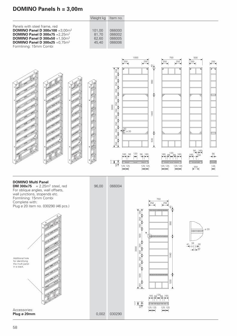
Panels with steel frame, redDOMINO Panel D 300x100 =3,00m2 101,00 066000DOMINO Panel D 300x75 =2,25m2 81,70 066002DOMINO Panel D 300x50 =1,50m2 62,60 066005DOMINO Panel D 300x25 =0,75m2 45,40 066006Formlining: 15mm Combi
DOMINO Multi PanelDM 300x75 = 2.25m2 steel, red 96,00 066004For oblique angles, wall offsets,wall junctions, stopends etc.Formlining: 15mm CombiComplete with:Plug ø 20 item no. 030290 (46 pcs.)
Accessories:Plug ø 20mm 0,002 030290
Weight kg Item no.
DOMINO Panels h = 3,00m
Additional holefor identifyingthe multi panelin a stack.
3000
238
246
263
240
250
250
530
1440
990
203
250
250
250
297
260
250
40
ø 20
30 40
x
492
25011
7
250
75°
117
117
250
250
250
3000
250
250
250
250
250
250
250
250
250
117
3000
25
50
430 527
430
40
1033
470135°
320135°
3000
90°
120
12012
0 60
935036
59
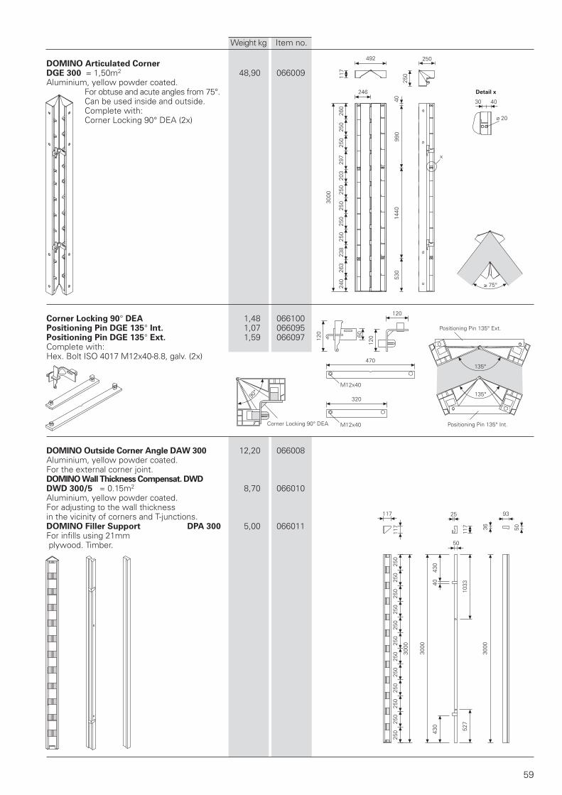
DOMINO Articulated CornerDGE 300 = 1,50m2 48,90 066009Aluminium, yellow powder coated.
For obtuse and acute angles from 75°.Can be used inside and outside.Complete with:Corner Locking 90° DEA (2x)
Corner Locking 90° DEA 1,48 066100Positioning Pin DGE 135° Int. 1,07 066095Positioning Pin DGE 135° Ext. 1,59 066097Complete with:Hex. Bolt ISO 4017 M12x40-8.8, galv. (2x)
DOMINO Outside Corner Angle DAW 300 12,20 066008Aluminium, yellow powder coated.For the external corner joint.DOMINO Wall Thickness Compensat. DWDDWD 300/5 = 0.15m2 8,70 066010Aluminium, yellow powder coated.For adjusting to the wall thicknessin the vicinity of corners and T-junctions.DOMINO Filler Support DPA 300 5,00 066011For infills using 21mm plywood. Timber.
Weight kg Item no.
Detail x
M12x40
M12x40Corner Locking 90° DEA
Positioning Pin 135° Ext.
Positioning Pin 135° Int.

60
PERI_International.indd 32 17.09.2007 14:29:57 Uhr

61
PERI_International.indd 33 17.09.2007 14:29:57 Uhr
62
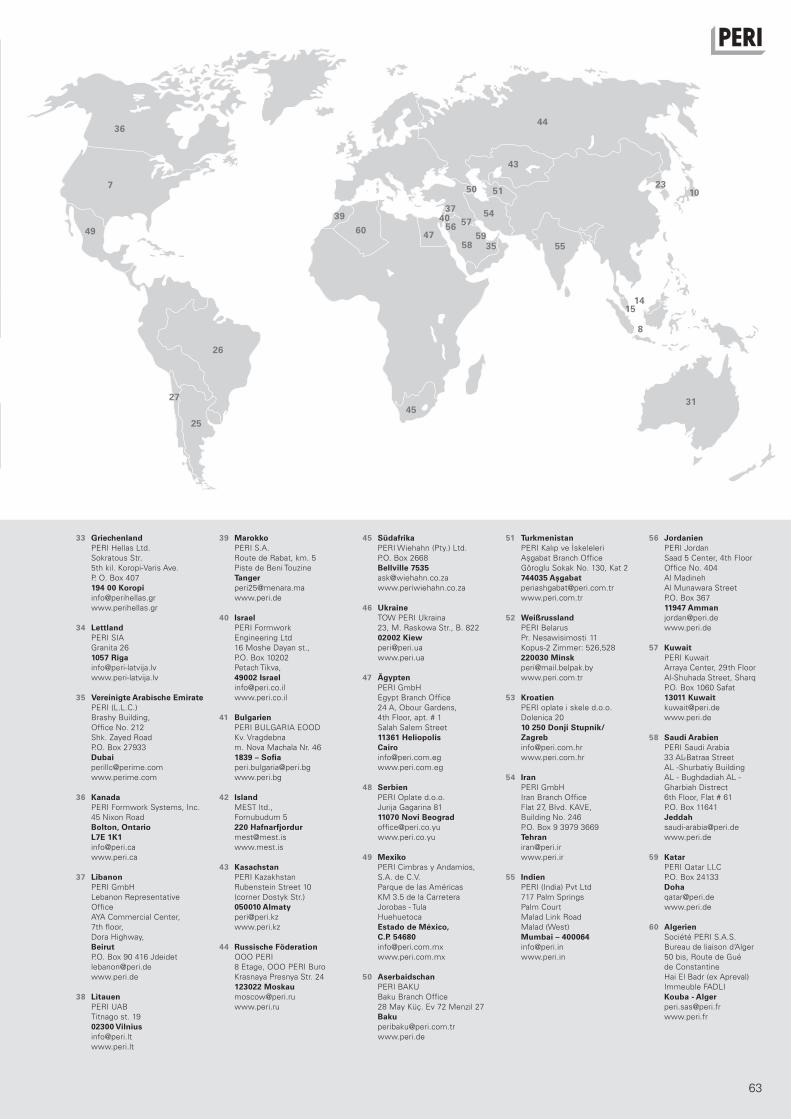
02 PERI S.A.S.
Zone Industrielle Nord
34-36 rue des Frères Lumière
77109 Meaux Cedex [email protected]
www.peri.fr
03 PERI AG
Aspstraße 17
8472 Ohringen [email protected]
www.peri.ch
04 PERI S.A. Sociedad
Unipersonal
Ctra. Paracuellos -
Fuente el Saz km. 18,9
Camino de Malatones, km. 0,5
28110 Algete/Madrid [email protected]
www.peri.es
05 N.V. PERI S.A.
Industriepark
Nijverheidsstraat 6 PB 54
1840 Londerzeel [email protected]
www.peri.be
06 PERI B.V.
v. Leeuwenhoekweg 23
Postbus 304
5480 AH-Schijndel [email protected]
www.peri.nl
07 PERI Formwork Systems, Inc.
7135 Dorsey Run Road
Elkridge, MD 21075 [email protected]
www.peri-usa.com
08 PT Beton Perkasa Wijaksana
P.O. Box 3737
Jakarta 10210 [email protected]
www.peri.de
09 PERI S.p.A.
Via G. Pascoli, 4
20060 Basiano (MI) [email protected]
www.peri.it
10 PERI Japan K.K.
7F Hakozaki 314 Building,
31-4 Hakozaki-cho,
Nihonbashi Chuo-ku
Tokyo 103-0015 [email protected]
www.perijapan.jp
11 PERI Ltd.
Market Harborough Road
Clifton upon Dunsmore
Rugby, CV23 0AN [email protected]
www.peri.ltd.uk
12 PERI Kalıp ve İskeleleri
San. ve Tic. Ltd. Sti.
Çakmaklı Mahallesi
Akçaburgaz Cad.
72. Sokak No: 23
Kıraç - Büyükçekmece/ Istanbul 34500 [email protected]
www.peri.com.tr
13 PERI Kft.
Zádor u. 4.
1181 Budapest [email protected]
www.peri.hu
14 PERI Formwork Malaysia
Sdn. Bhd.
Unit 19-07-4, Level 7
PNB Damansara
19 Lorong Dungun
Damansara Heights
50490 Kuala Lumpur [email protected]
www.perimalaysia.com
15 PERI ASIA Pte. Ltd
Formwork Pte. Ltd.
No. 1 Sims Lane # 06-10
Singapore 387355 [email protected]
www.periasia.com
16 PERI Ges.mbH
Traisenstraße 3
3134 Nußdorf ob der Traisen [email protected]
www.peri.at
17 PERI spol. s r.o.
Průmyslová 392
252 42 Jesenice [email protected]
www.peri.cz
18 PERI Danmark A/S
forskalling og stillads
Greve Main 26
2670 Greve [email protected]
www.peri.dk
19 PERI Suomi Ltd. Oy
Hakakalliontie 5
05460 Hyvinkää [email protected]
www.perisuomi.fi
20 PERI NORGE AS
Kobbervikdalen 156
3036 Drammen [email protected]
www.peri.no
21 PERI Polska Sp. z o.o.
ul. Stołeczna 62
05-860 Płochocin [email protected]
www.peri.pl.pl
22 PERIform SVERIGE AB
Montörgatan 4-6
Box 9073
30013 Halmstad [email protected]
www.periform.se
23 PERI (Korea) Ltd.
8-9th Fl., Yuseong Bldg.
830-67, Yeoksam-dong,
Kangnam-ku,
Seoul 135-080 [email protected]
www.perikorea.com
24 PERIcofragens Lda.
Cofragens e Andaimes
Rua Cesário Verde,
nº 5 - 3º Esq.
Linda-a-Pastora 2790-326 Queijas [email protected]
www.peri.pt
25 PERI S.A.
Ruta Nacional N°. 9, km 47,5
(Panamericana Ramal Escobar)
(1625) Escobar/Prov. Bs. As. [email protected]
www.peri.com.ar
26 PERI Formas e
Escoramentos Ltda.
Rodovia Raposo Tavares,
km 41
Colinas Bandeirante
CEP 06730-000 Vargem Grande Paulista São Paulo [email protected]
www.peribrasil.com.br
27 PERI Chile Ltda.
C/José de San Martin N° 104
Parque Industrial Los
Libertadores
Colina, Santiago de Chile [email protected]
www.peri.cl
28 PERI România SRL
Calea Bucureşti nr. 2B
077015 Baloteşti - ILFOV [email protected]
www.peri.ro
29 PERI SLOWENIEN
Goran Opalic
Obrežna 137
2000 Maribor [email protected]
www.peri.de
30 PERI spol. s r.o.
Šamorínska 18
903 01 Senec [email protected]
www.peri.sk
31 PERI Australia Pty. Ltd.
116 Glendenning Road
Glendenning NSW 2761 [email protected]
www.periaus.com.au
32 PERI AS
Valdmäe 8
Tänassilma Tehnopark
76401 Saku vald Harjumaa
www.peri.ee
2
1
3
4
5
6
9
11
12
1316
17
18
19
20
22
21
24
2829
30
32
33
34
38
41
42
46
48
52
53
01 PERI GmbH Rudolf-Diesel-Straße
89264 Weißenhorn
www.peri.de
Frankreich
Schweiz
Spanien
Belgien/Luxemburg
Niederlande
USA
Indonesien
Italien
Japan
Großbritannien/Irland
Türkei
Ungarn
Malaysia
Singapur
Österreich
Tschechische Republik
Dänemark
Finnland
Norwegen
Polen
Schweden
Korea
Portugal
Argentinien
Brasilien
Chile
Rumänien
Slowenien
Slowakei
Australien
Estland
PERI International
PERI_International.indd 32 17.09.2007 14:28:40 Uhr
63
33 PERI Hellas Ltd.
Sokratous Str.
5th kil. Koropi-Varis Ave.
P. O. Box 407
194 00 Koropi [email protected]
www.perihellas.gr
34 PERI SIA
Granita 26
1057 Riga [email protected]
www.peri-latvija.lv
35 PERI (L.L.C.)
Brashy Building,
Office No. 212
Shk. Zayed Road
P.O. Box 27933
Dubai [email protected]
www.perime.com
36 PERI Formwork Systems, Inc.
45 Nixon Road
Bolton, Ontario L7E 1K1 [email protected]
www.peri.ca
37 PERI GmbH
Lebanon Representative
Office
AYA Commercial Center,
7th floor,
Dora Highway,
Beirut P.O. Box 90 416 Jdeidet
www.peri.de
38 PERI UAB
Titnago st. 19
02300 Vilnius [email protected]
www.peri.lt
39 PERI S.A.
Route de Rabat, km. 5
Piste de Beni Touzine
Tanger [email protected]
www.peri.de
40 PERI Formwork
Engineering Ltd
16 Moshe Dayan st.,
P.O. Box 10202
Petach Tikva,
49002 Israel [email protected]
www.peri.co.il
41 PERI BULGARIA EOOD
Kv. Vragdebna
m. Nova Machala Nr. 46
1839 – Sofia [email protected]
www.peri.bg
42 MEST ltd.,
Fornubudum 5
220 Hafnarfjordur [email protected]
www.mest.is
43 PERI Kazakhstan
Rubenstein Street 10
(corner Dostyk Str.)
050010 Almaty [email protected]
www.peri.kz
44 OOO PERI
8 Etage, OOO PERI Buro
Krasnaya Presnya Str. 24
123022 Moskau [email protected]
www.peri.ru
45 PERI Wiehahn (Pty.) Ltd.
P.O. Box 2668
Bellville 7535 [email protected]
www.periwiehahn.co.za
46 TOW PERI Ukraina
23, M. Raskowa Str., B. 822
02002 Kiew [email protected]
www.peri.ua
47 PERI GmbH
Egypt Branch Office
24 A, Obour Gardens,
4th Floor, apt. # 1
Salah Salem Street
11361 Heliopolis Cairo [email protected]
www.peri.com.eg
48 PERI Oplate d.o.o.
Jurija Gagarina 81
11070 Novi Beograd [email protected]
www.peri.co.yu
49 PERI Cimbras y Andamios,
S.A. de C.V.
Parque de las Américas
KM 3.5 de la Carretera
Jorobas - Tula
Huehuetoca
Estado de México, C.P. 54680 [email protected]
www.peri.com.mx
50 PERI BAKU
Baku Branch Office
28 May Küç. Ev 72 Menzil 27
Baku [email protected]
www.peri.de
51 PERI Kalıp ve İskeleleri
Aşgabat Branch Office
Göroglu Sokak No. 130, Kat 2
744035 Aşgabat [email protected]
www.peri.com.tr
52 PERI Belarus
Pr. Nesawisimosti 11
Kopus-2 Zimmer: 526,528
220030 Minsk [email protected]
www.peri.com.tr
53 PERI oplate i skele d.o.o.
Dolenica 20
10 250 Donji Stupnik/ Zagreb [email protected]
www.peri.com.hr
54 PERI GmbH
Iran Branch Office
Flat 27, Blvd. KAVE,
Building No. 246
P.O. Box 9 3979 3669
Tehran [email protected]
www.peri.ir
55 PERI (India) Pvt Ltd
717 Palm Springs
Palm Court
Malad Link Road
Malad (West)
Mumbai – 400064 [email protected]
www.peri.in
56 PERI Jordan
Saad 5 Center, 4th Floor
Office No. 404
Al Madineh
Al Munawara Street
P.O. Box 367
11947 Amman [email protected]
www.peri.de
57 PERI Kuwait
Arraya Center, 29th Floor
Al-Shuhada Street, Sharq
P.O. Box 1060 Safat
13011 Kuwait [email protected]
www.peri.de
58 PERI Saudi Arabia
33 AL-Batraa Street
AL -Shurbatiy Building
AL - Bughdadiah AL -
Gharbiah Distrect
6th Floor, Flat # 61
P.O. Box 11641
Jeddah [email protected]
www.peri.de
59 PERI Qatar LLC
P.O. Box 24133
Doha [email protected]
www.peri.de
60 Société PERI S.A.S.
Bureau de liaison d‘Alger
50 bis, Route de Gué
de Constantine
Hai El Badr (ex Apreval)
Immeuble FADLI
Kouba - Alger [email protected]
www.peri.fr
7
8
10
1415
23
25
26
27 31
35
36
3739 40
43
44
45
4749
50 51
54
595558
5760 56
Griechenland
Lettland
Vereinigte Arabische Emirate
Kanada
Libanon
Litauen
Marokko
Israel
Bulgarien
Island
Kasachstan
Russische Föderation
Südafrika
Ukraine
Ägypten
Serbien
Mexiko
Aserbaidschan
Turkmenistan
Weißrussland
Kroatien
Iran
Indien
Jordanien
Kuwait
Saudi Arabien
Katar
Algerien
PERI_International.indd 33 17.09.2007 14:28:41 Uhr
D e
09
/20
07
2m
a
Art
. N
r.:
79
219
6
© C
opyri
gh
t by P
ER
I G
mb
H
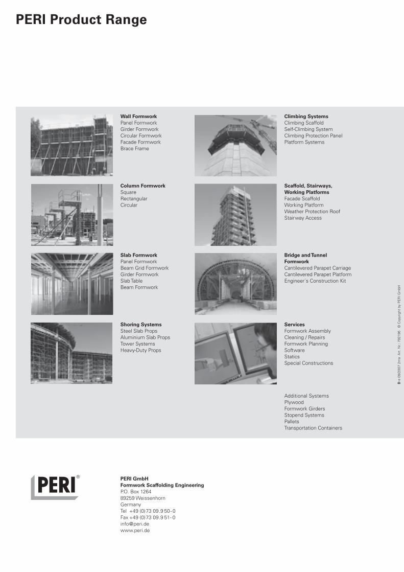
Wall FormworkPanel Formwork
Girder Formwork
Circular Formwork
Facade Formwork
Brace Frame
Column FormworkSquare
Rectangular
Circular
Slab FormworkPanel Formwork
Beam Grid Formwork
Girder Formwork
Slab Table
Beam Formwork
Shoring SystemsSteel Slab Props
Aluminium Slab Props
Tower Systems
Heavy-Duty Props
Climbing SystemsClimbing Scaffold
Self-Climbing System
Climbing Protection Panel
Platform Systems
Scaffold, Stairways, Working PlatformsFacade Scaffold
Working Platform
Weather Protection Roof
Stairway Access
Bridge and Tunnel FormworkCantilevered Parapet Carriage
Cantilevered Parapet Platform
Engineer´s Construction Kit
ServicesFormwork Assembly
Cleaning / Repairs
Formwork Planning
Software
Statics
Special Constructions
Additional Systems
Plywood
Formwork Girders
Stopend Systems
Pallets
Transportation Containers
PERI GmbHFormwork Scaffolding EngineeringP.O. Box 1264
89259 Weissenhorn
Germany
Tel +49 (0)73 09.9 50- 0
Fax +49 (0)73 09.9 51- 0
www.peri.de
PERI Product Range
Titel_AuV_Domino mit U4.indd 1 24.09.2007 15:52:55 Uhr