Embed Size (px)
Citation preview
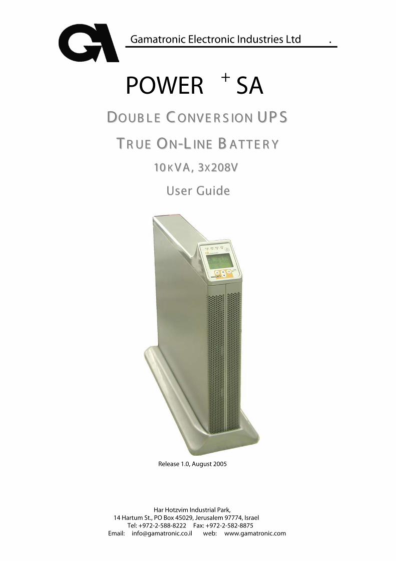
Gamatronic Electronic Industries Ltd .
Har Hotzvim Industrial Park, 14 Hartum St., PO Box 45029, Jerusalem 97774, Israel
Tel: +972-2-588-8222 Fax: +972-2-582-8875 Email: [email protected] web: www.gamatronic.com
POWER + SA DDOO UU BB LL EE CC OO NNVV EE RR SS IIOO NN UU PP SS
TT RR UU EE OO NN--LL IINNEE BB AA TT TT EE RR YY 1010 KK VV AA ,, 33XX 220088VV
User Guide
Release 1.0, August 2005
Gamatronic Electronic Industries Ltd.
Page ii POWER+ SA User GuideRelease 1.0
Gamatronic Electronic Industries Ltd. Har Hotzvim Industrial Park 14 Hartum St. PO Box 45029 Jerusalem 97774 Israel Tel: +972-2-588-8222 Fax: +972-2-582-8875 Email: [email protected] Website: www.gamatronic.com This UPS has been designed for commercial/industrial use only, and is not for use in any life support application. Copyright by Gamatronic Electronic Industries Ltd., 2005. All rights reserved worldwide. The information contained in this document is proprietary and is subject to all relevant copyright, patent and other laws protecting intellectual property, as well as any specific agreement protecting Gamatronic Electronic Industries Ltd. rights in the aforesaid information. Neither this document nor the information contained herein may be published, or reproduced, in whole or in part, without the express, prior, written permission of Gamatronic Electronic Industries Ltd. In addition, any use of this document or the information contained herein for any purposes other than those for which it was disclosed is strictly forbidden. Gamatronic Electronic Industries Ltd. reserves the right, without prior notice or liability, to make changes in equipment design or specifications. Information supplied by Gamatronic Electronic Industries Ltd. is believed to be accurate and reliable. However, no responsibility is assumed by Gamatronic Electronic Industries Ltd. for the use thereof nor for the rights of third parties which may be affected in any way by the use thereof. Any representation(s) in this document concerning performance of Gamatronic Electronic Industries Ltd. product(s) are for informational purposes only and are not warranties of future performance, either express or implied. Gamatronic Electronic Industries Ltd. standard limited warranty, available upon request, stated in its sales contract or order confirmation form, is the only warranty offered by Gamatronic Electronic Industries Ltd. in relation thereto. This document may contain flaws, omissions or typesetting errors; no warranty is granted nor liability assumed in relation thereto unless specifically undertaken in Gamatronic Electronic Industries Ltd. sales contract or order confirmation. Information contained herein is periodically updated and changes will be incorporated into subsequent editions. If you have encountered an error, please notify Gamatronic Electronic Industries Ltd. All specifications are subject to change without prior notice.
Gamatronic Electronic Industries Ltd.
POWER+ SA User Guide Release 1.0
Page iii
TABLE OF CONTENTS SAFETY CONSIDERATIONS............................................................................................................. V
Do’s ...................................................................................................................................v Don’ts ................................................................................................................................v
1. INTRODUCTION ................................................................................................................... 6 Major Parts of the POWER+ SA ...................................................................................... 7 Control Panel.................................................................................................................... 7 Charger............................................................................................................................. 7 Inverter ............................................................................................................................. 8 Static Switch (ST/SW) ...................................................................................................... 8 Battery .............................................................................................................................. 8
2. OPERATING MODES............................................................................................................ 9 Normal Mode.................................................................................................................... 9 Battery Mode .................................................................................................................. 10 Bypass Mode.................................................................................................................. 10
3. USER INTERFACE.............................................................................................................. 11 Control Panel.................................................................................................................. 11 On/Off Button.................................................................................................................. 12 Navigation Keypad ......................................................................................................... 12 Indicators ........................................................................................................................ 12 The POWER+ Display Screen ....................................................................................... 13 The Main Screen ............................................................................................................ 13 Normal Mode.................................................................................................................. 15 Battery Mode .................................................................................................................. 17 Bypass Mode.................................................................................................................. 20 UPS Off .......................................................................................................................... 21 Status Screens ............................................................................................................... 23 UPS Profile screens ....................................................................................................... 23 AC Output screen........................................................................................................... 24 AC Input screen.............................................................................................................. 24 Bypass screen................................................................................................................ 25 Inverter SCREEn............................................................................................................ 25 Battery SCREEN ............................................................................................................ 26 The Power+ SA Main Menu ............................................................................................ 27
4. DAILY OPERATION ............................................................................................................ 28 POWER+ SA Start-up .................................................................................................... 28 POWER+ SA Shutdown................................................................................................. 29
5. THE EVENT LOG............................................................................................................... 30 Alarms ............................................................................................................................ 30 Navigating to the event log............................................................................................. 30 Active Alarm display ....................................................................................................... 30 Event log entries............................................................................................................. 31 Resetting the event log................................................................................................... 31
6. BATTERY TESTS............................................................................................................... 35 Automatic battery test..................................................................................................... 35 Manual battery test......................................................................................................... 35
7. FIRST-TIME SETUP ........................................................................................................... 36 Cable Connections......................................................................................................... 36 Installation and Start-Up Sequence ............................................................................... 40 To start the UPS: ............................................................................................................ 40 Set the output voltage .................................................................................................... 40 Set the system clock ...................................................................................................... 40 Modify the screen contrast (optional) ............................................................................. 40 Set Automatic Restart mode (optional) .......................................................................... 40 Operation........................................................................................................................ 41
8. SETTING SYSTEM PARAMETERS ........................................................................................ 42 Setting the system clock ................................................................................................ 42 Setting screen contrast .................................................................................................. 43
Gamatronic Electronic Industries Ltd.
Page iv POWER+ SA User GuideRelease 1.0
Setting the output voltage............................................................................................... 44 9. AUTOMATIC RESTART....................................................................................................... 45
Determining the current automatic restart setting .......................................................... 45 Changing the automatic restart status ........................................................................... 45
10. MISCELLANEOUS FUNCTIONS............................................................................................ 47 Manually entering or leaving Bypass Mode ................................................................... 47
11. IN THE EVENT OF AN AC POWER OUTAGE........................................................................... 49 12. TROUBLESHOOTING.......................................................................................................... 52
Alarm sounds and/or Alarm LED lights up ..................................................................... 52 Electricity returned but UPS remains in Battery Mode................................................... 52 Battery Test failed .......................................................................................................... 52 The UPS remains in Bypass mode ................................................................................ 52 Sync Fault ...................................................................................................................... 52
13. RS232 INTERFACE........................................................................................................... 53 14. SNMP AGENT (OPTIONAL)................................................................................................. 54 15. WIRELESS CONTROL (OPTIONAL) ...................................................................................... 55
WING Configurations ..................................................................................................... 56 16. POWER+ SA SPECIFICATIONS ........................................................................................ 58
Gamatronic Electronic Industries Ltd.
POWER+ SA User Guide Release 1.0
Page v
SAFETY CONSIDERATIONS
The POWER+ SA UPS system is designed for industrial applications and harsh environments. Nevertheless the POWER+ SA UPS system is a sophisticated power system and should be handled with appropriate care, following these guidelines.
Do’s • Read this manual carefully before starting installation and operation of the
UPS. • Review the safety precautions described below to avoid injury to users or
damaging equipment. • All power connections must be completed by a licensed electrician who is
experienced in wiring this type of equipment, and who is knowledgeable about all federal, state, and local electrical codes and regulations. Improper wiring may cause damage to the equipment or injury to personnel.
• Pay attention to the warning signs, labels and marks on the unit. A warning sign signals the presence of a possibly serious, life-threatening condition.
• Keep the surroundings clean, uncluttered and free from excess moisture. • Allow only qualified technicians to service the UPS. There are no user-
serviceable components. Do not try to repair it yourself! • Use the UPS only for its intended purpose.
WARNING - RISK OF LETHAL ELECTRIC SHOCK: The battery drawer contains a series of 12-Volt batteries that provide high voltage and energy in the UPS body even when the UPS is not connected to the AC input. Appropriate precautions should be taken during installation, inspection and servicing.
Don’ts • Do not open the cover of the UPS or the battery cabinets under any
circumstances. All UPS panels and doors should be closed. • Do not insert any objects through the ventilation holes. • Do not put objects on the UPS. • Do not move the UPS while it is operating. • Do not use the UPS outdoors. • Do not turn the UPS upside down during transportation. • Do not connect or disconnect the cable to the battery cabinet before the battery
circuit breaker is turned OFF. • Do not turn ON the battery circuit breaker when the battery cabinet is
disconnected from the UPS. • Do not install next to any gas or electrical heaters. A restricted location is
recommended in order to prevent access by unauthorized personnel.
Gamatronic Electronic Industries Ltd.
POWER+ SA User Guide Release 1.0
Page 6
1. INTRODUCTION
Thank you for purchasing a POWER+ SA UPS system. POWER+ SA is one of the most sophisticated UPSs on the market today. In general, an Uninterruptible Power Supply (UPS) provides backup power for use when the utility AC electric power mains fail or drop to an unacceptable voltage level. POWER+ SA answers this critical need, and more.
POWER+ SA is designed to protect your data and equipment and minimize downtime and other adverse effects normally incurred by power irregularities and failures.
POWER+ SA continually eliminates surges, spikes and sags that are inherent in commercial utility power. Over time, these irregularities shorten the life of equipment and components. The efficiency of POWER+ SA thus helps to extend the life of your equipment, even during normal use when the input power is constant and continuous. POWER+ SA is unique because it • Is a true on-line battery design according to IEC 62040-31.
• Is a "green" power solution thanks to THD of 5% at the input, and provides
“clean” power to your loads.
• Has an overall efficiency of up to 96% and backup efficiency of 98%.
• Is relatively light and small.
POWER+ SA requires little attention or intervention during normal operation; however, you should read and understand the procedures described in this manual to ensure trouble-free operation.
1 IEC 62040-3 is a standard for UPSs, authored by the International Electrotechnical Commission (IEC). The IEC is the leading global organization that prepares and publishes international standards for all electrical, electronic and related technologies. These serve as a basis for national standardization and as references when drafting international tenders and contracts.
Gamatronic Electronic Industries Ltd.
POWER+ SA User Guide Release 1.0
Page 7
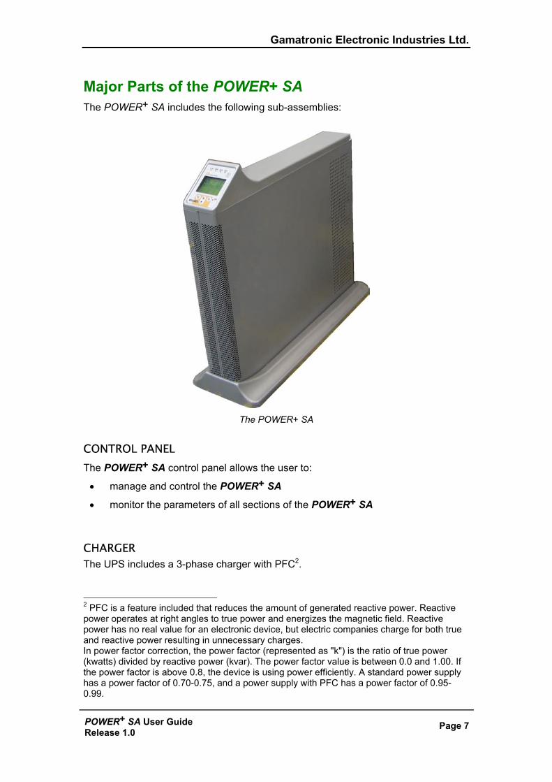
Major Parts of the POWER+ SA The POWER+ SA includes the following sub-assemblies:
The POWER+ SA
CONTROL PANEL The POWER+ SA control panel allows the user to:
• manage and control the POWER+ SA
• monitor the parameters of all sections of the POWER+ SA
CHARGER The UPS includes a 3-phase charger with PFC2.
2 PFC is a feature included that reduces the amount of generated reactive power. Reactive power operates at right angles to true power and energizes the magnetic field. Reactive power has no real value for an electronic device, but electric companies charge for both true and reactive power resulting in unnecessary charges. In power factor correction, the power factor (represented as "k") is the ratio of true power (kwatts) divided by reactive power (kvar). The power factor value is between 0.0 and 1.00. If the power factor is above 0.8, the device is using power efficiently. A standard power supply has a power factor of 0.70-0.75, and a power supply with PFC has a power factor of 0.95-0.99.
Gamatronic Electronic Industries Ltd.
Page 8 POWER+ SA User GuideRelease 1.0
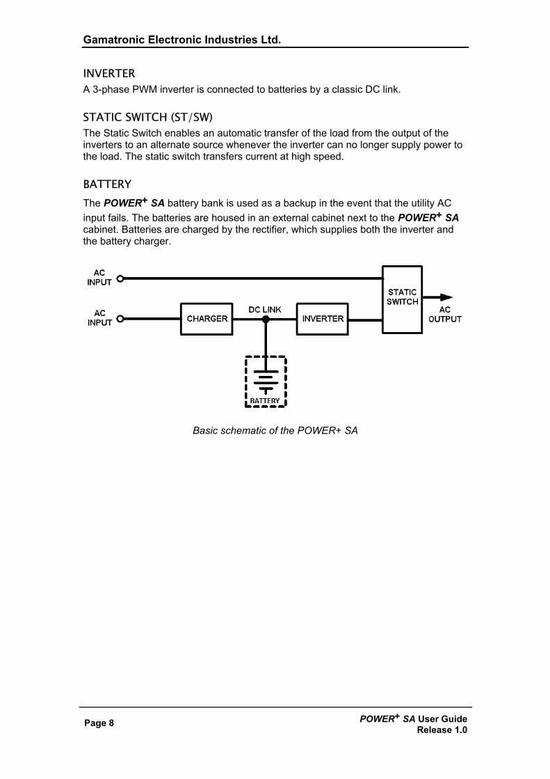
INVERTER A 3-phase PWM inverter is connected to batteries by a classic DC link.
STATIC SWITCH (ST/SW) The Static Switch enables an automatic transfer of the load from the output of the inverters to an alternate source whenever the inverter can no longer supply power to the load. The static switch transfers current at high speed.
BATTERY The POWER+ SA battery bank is used as a backup in the event that the utility AC input fails. The batteries are housed in an external cabinet next to the POWER+ SA cabinet. Batteries are charged by the rectifier, which supplies both the inverter and the battery charger.
Basic schematic of the POWER+ SA
Gamatronic Electronic Industries Ltd.
POWER+ SA User Guide Release 1.0
Page 9
2. OPERATING MODES
The POWER+ SA is installed between the power mains and your load devices, and supplies AC electrical power to your equipment. The POWER+ SA has three automatic modes of operation:
• Normal mode • Battery mode • Bypass mode
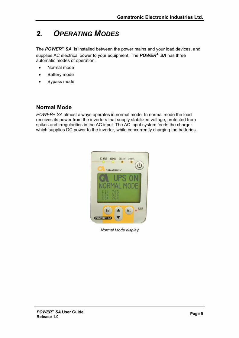
Normal Mode POWER+ SA almost always operates in normal mode. In normal mode the load receives its power from the inverters that supply stabilized voltage, protected from spikes and irregularities in the AC input. The AC input system feeds the charger which supplies DC power to the inverter, while concurrently charging the batteries.
Normal Mode display
Gamatronic Electronic Industries Ltd.
Page 10 POWER+ SA User GuideRelease 1.0
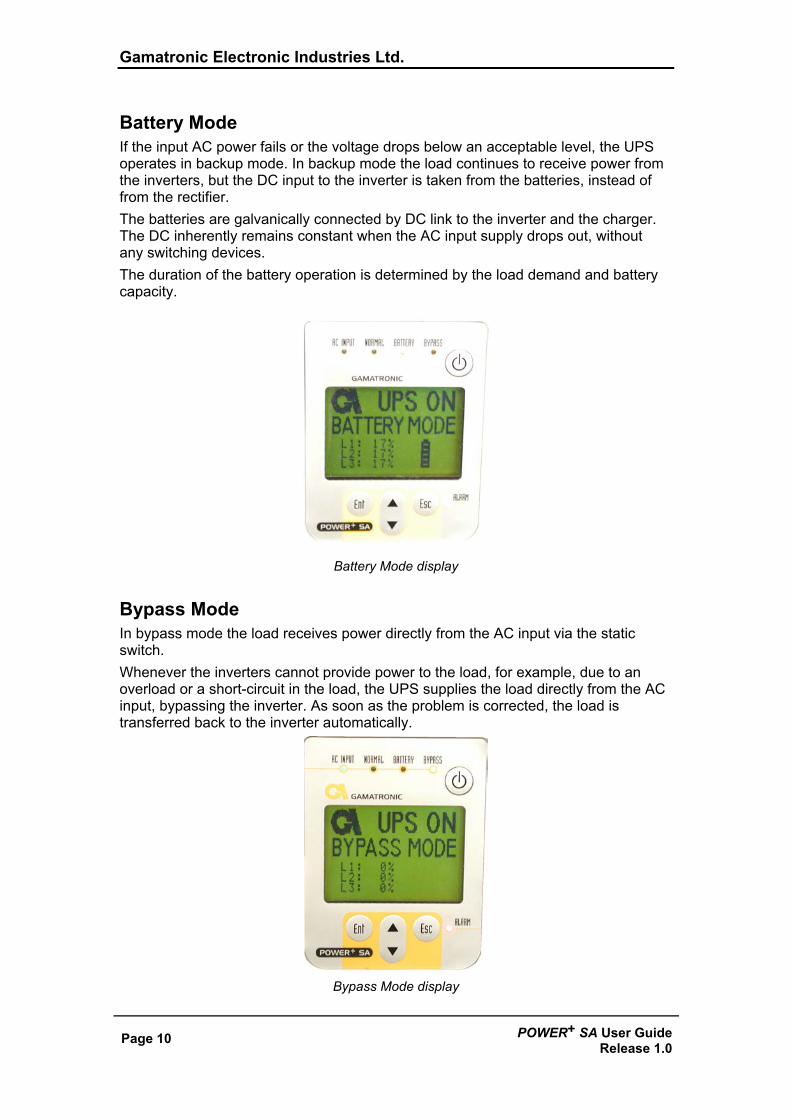
Battery Mode If the input AC power fails or the voltage drops below an acceptable level, the UPS operates in backup mode. In backup mode the load continues to receive power from the inverters, but the DC input to the inverter is taken from the batteries, instead of from the rectifier. The batteries are galvanically connected by DC link to the inverter and the charger. The DC inherently remains constant when the AC input supply drops out, without any switching devices. The duration of the battery operation is determined by the load demand and battery capacity.
Battery Mode display
Bypass Mode In bypass mode the load receives power directly from the AC input via the static switch. Whenever the inverters cannot provide power to the load, for example, due to an overload or a short-circuit in the load, the UPS supplies the load directly from the AC input, bypassing the inverter. As soon as the problem is corrected, the load is transferred back to the inverter automatically.
Bypass Mode display
Gamatronic Electronic Industries Ltd.
POWER+ SA User Guide Release 1.0
Page 11
3. USER INTERFACE
This section describes the buttons and indicators used to operate the POWER+ SA.
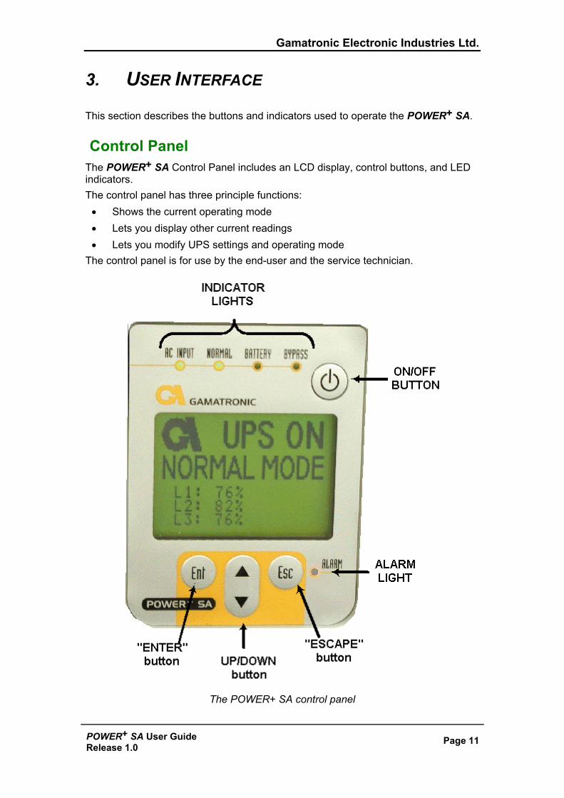
Control Panel The POWER+ SA Control Panel includes an LCD display, control buttons, and LED indicators. The control panel has three principle functions:
• Shows the current operating mode • Lets you display other current readings • Lets you modify UPS settings and operating mode
The control panel is for use by the end-user and the service technician.
The POWER+ SA control panel
Gamatronic Electronic Industries Ltd.
Page 12 POWER+ SA User GuideRelease 1.0
On/Off Button
To turn the UPS on, press the button twice.
To turn the UPS off, press the button twice.
Navigation Keypad The control panel’s keypad consists of three buttons.
• The UP/DOWN key is used to navigate through screens and browse the Event Log.
• The Ent (Enter) key is used to select an item or apply a change.
• The Esc (Escape) key returns you to the Main Screen. During an active alarm condition, pressing the Esc button from the Main Screen silences the audible alarm.
Indicators The top of the control panel contains four LCD indicators. The status indicators show what is running and how the UPS is providing power to the load. The table shows the color and meaning of the LCD status indicators when lit.
AC INPUT Green – AC input is present and within normal range.
NORMAL Green – The UPS is in normal mode.
BATTERY Yellow – The UPS is in Battery mode
BYPASS Yellow – The UPS is in Bypass mode
ALARM Red – Indicates an alarm condition. To determine the nature of the alarm: From the Main Screen press Ent to display the main menu, press Ent again to see the Alarm Status, press Ent once more to see the Event Log.
Gamatronic Electronic Industries Ltd.
POWER+ SA User Guide Release 1.0
Page 13
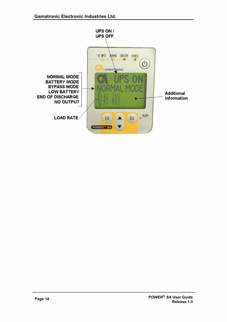
The POWER+ Display Screen The display screen on the POWER+ SA control panel shows the current operating mode and related critical data. There are several distinct data screens that can be shown on the POWER+ SA display screen.
The Main Screen The POWER+ SA Main Screen is the default display on the POWER+ SA screen. From any other screen, if the keyboard is not used for 45 seconds, the POWER+ SA returns to the Main Screen. The Main Screen shows the UPS’s current operating mode and other critical data. Other screens describing current operating conditions can be seen by navigating “upwards” or “downward” with the UP/DOWN key. The first line of the Main Screen shows whether the UPS is currently on or off. The second line tells you the most important information about the UPS’s current status. Most of the time it will read “NORMAL MODE”. The UPS can also automatically transfer to:
• BATTERY MODE • BYPASS MODE • UPS OFF
The L1, L2, and L3 numbers in the Main Screen show the current load rate as a percent of maximal AC load at each phase.
Gamatronic Electronic Industries Ltd.
Page 14 POWER+ SA User GuideRelease 1.0
Gamatronic Electronic Industries Ltd.
POWER+ SA User Guide Release 1.0
Page 15
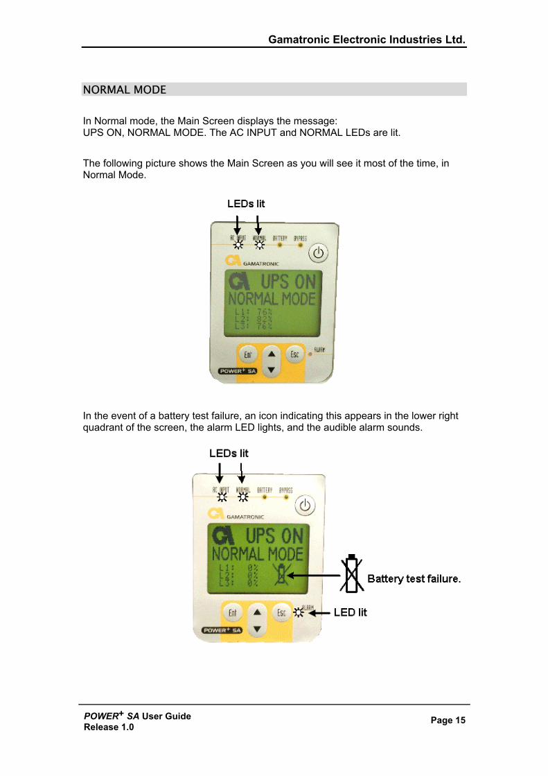
NORMAL MODE In Normal mode, the Main Screen displays the message: UPS ON, NORMAL MODE. The AC INPUT and NORMAL LEDs are lit. The following picture shows the Main Screen as you will see it most of the time, in Normal Mode.
In the event of a battery test failure, an icon indicating this appears in the lower right quadrant of the screen, the alarm LED lights, and the audible alarm sounds.
Gamatronic Electronic Industries Ltd.
Page 16 POWER+ SA User GuideRelease 1.0
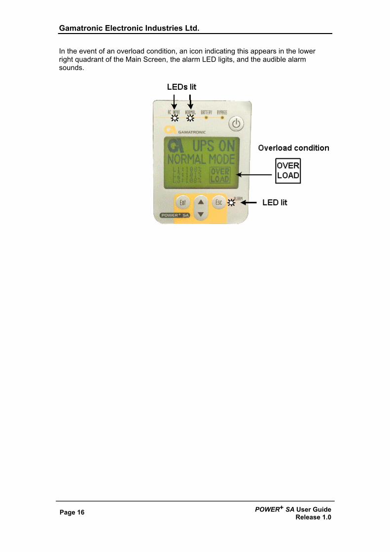
In the event of an overload condition, an icon indicating this appears in the lower right quadrant of the Main Screen, the alarm LED ligits, and the audible alarm sounds.
Gamatronic Electronic Industries Ltd.
POWER+ SA User Guide Release 1.0
Page 17
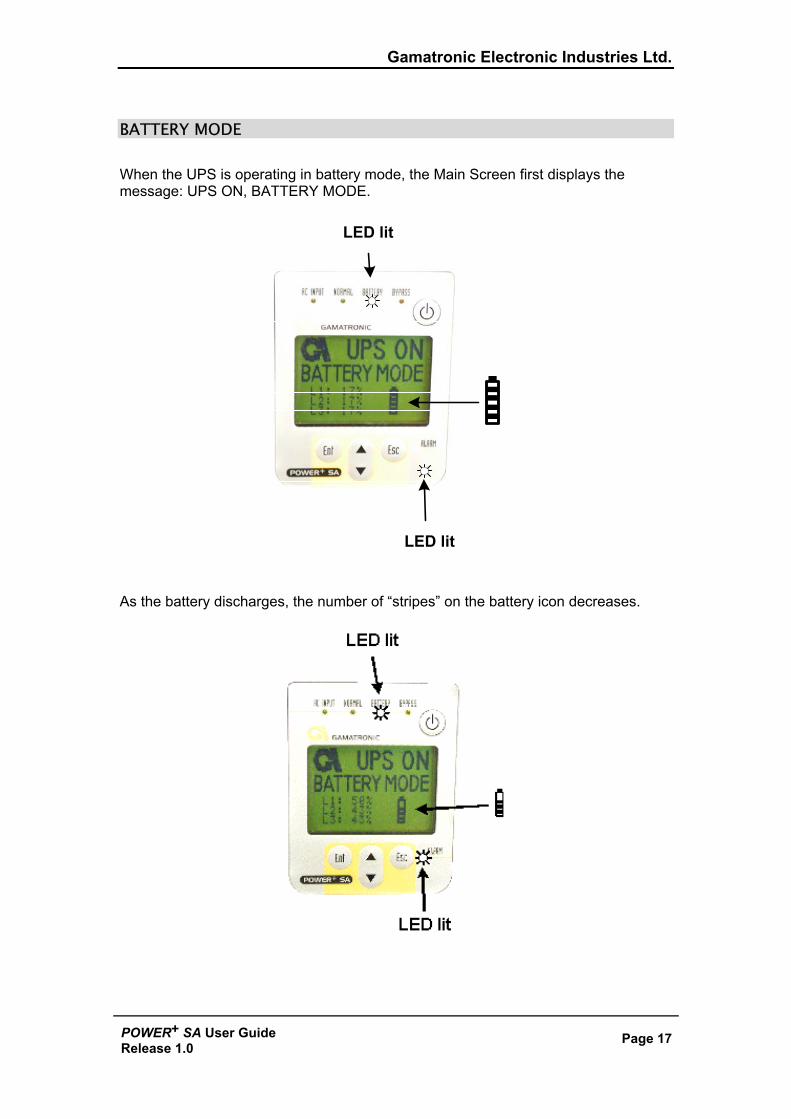
BATTERY MODE When the UPS is operating in battery mode, the Main Screen first displays the message: UPS ON, BATTERY MODE.
LED lit
LED lit
As the battery discharges, the number of “stripes” on the battery icon decreases.
Gamatronic Electronic Industries Ltd.
Page 18 POWER+ SA User GuideRelease 1.0
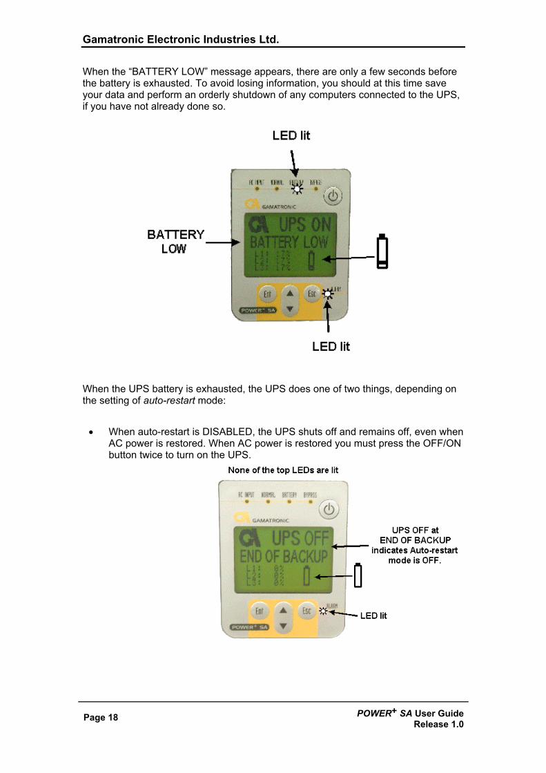
When the “BATTERY LOW” message appears, there are only a few seconds before the battery is exhausted. To avoid losing information, you should at this time save your data and perform an orderly shutdown of any computers connected to the UPS, if you have not already done so.
When the UPS battery is exhausted, the UPS does one of two things, depending on the setting of auto-restart mode:
• When auto-restart is DISABLED, the UPS shuts off and remains off, even when AC power is restored. When AC power is restored you must press the OFF/ON button twice to turn on the UPS.
Gamatronic Electronic Industries Ltd.
POWER+ SA User Guide Release 1.0
Page 19
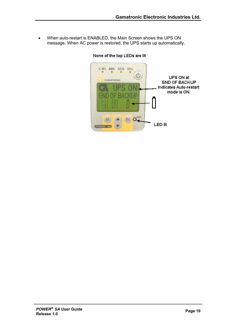
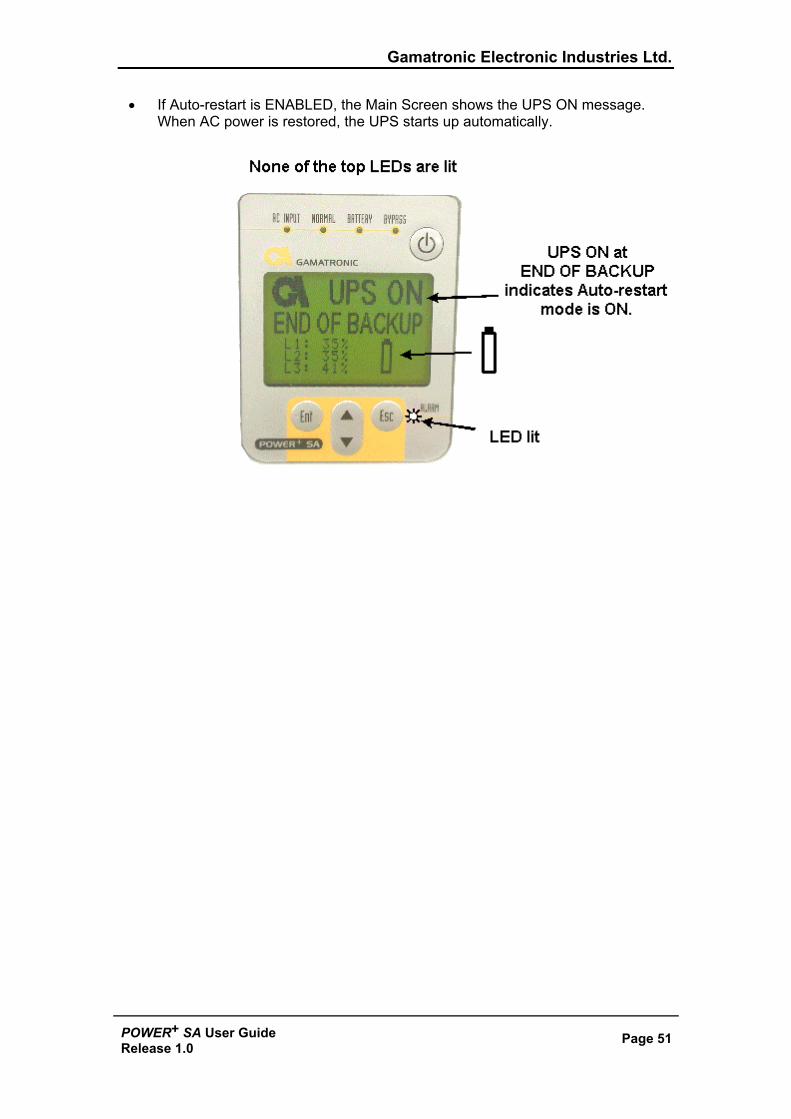
• When auto-restart is ENABLED, the Main Screen shows the UPS ON
message. When AC power is restored, the UPS starts up automatically.
Gamatronic Electronic Industries Ltd.
Page 20 POWER+ SA User GuideRelease 1.0
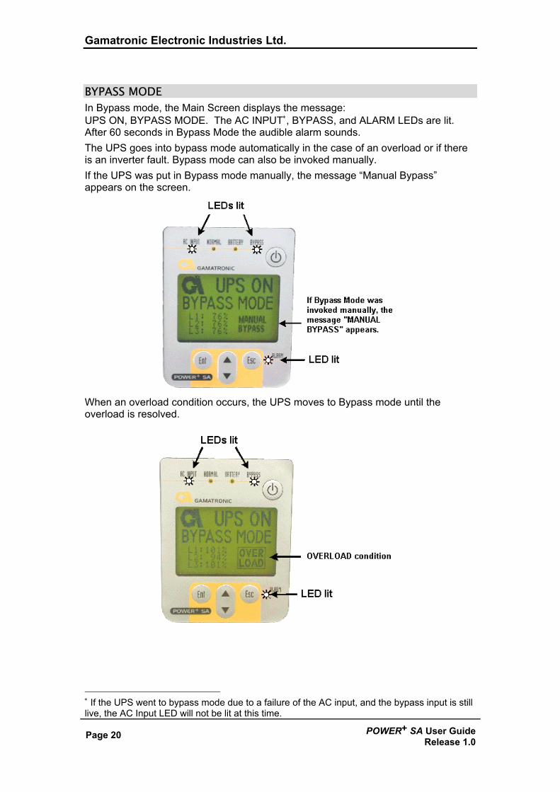
BYPASS MODE In Bypass mode, the Main Screen displays the message: UPS ON, BYPASS MODE. The AC INPUT∗, BYPASS, and ALARM LEDs are lit. After 60 seconds in Bypass Mode the audible alarm sounds. The UPS goes into bypass mode automatically in the case of an overload or if there is an inverter fault. Bypass mode can also be invoked manually. If the UPS was put in Bypass mode manually, the message “Manual Bypass” appears on the screen.
When an overload condition occurs, the UPS moves to Bypass mode until the overload is resolved.
∗ If the UPS went to bypass mode due to a failure of the AC input, and the bypass input is still live, the AC Input LED will not be lit at this time.
Gamatronic Electronic Industries Ltd.
POWER+ SA User Guide Release 1.0
Page 21
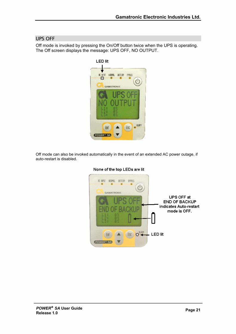
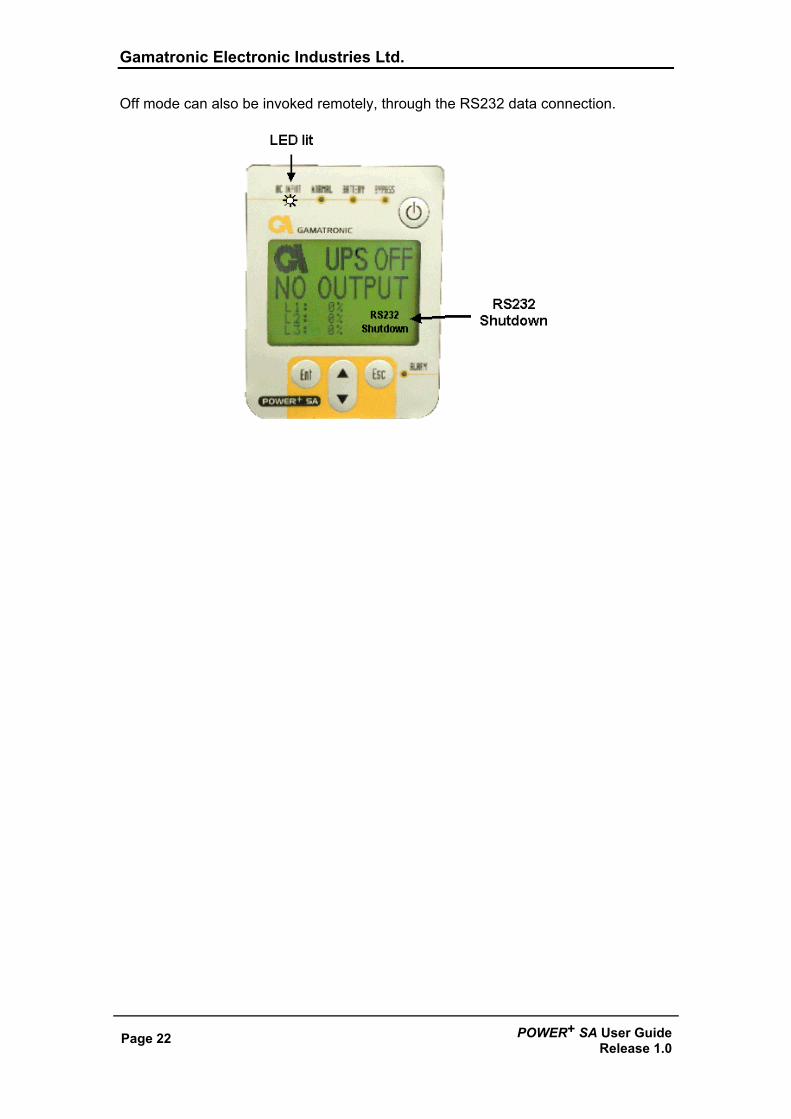
UPS OFF Off mode is invoked by pressing the On/Off button twice when the UPS is operating. The Off screen displays the message: UPS OFF, NO OUTPUT.
Off mode can also be invoked automatically in the event of an extended AC power outage, if auto-restart is disabled.
Gamatronic Electronic Industries Ltd.
Page 22 POWER+ SA User GuideRelease 1.0
Off mode can also be invoked remotely, through the RS232 data connection.
Gamatronic Electronic Industries Ltd.
POWER+ SA User Guide Release 1.0
Page 23
Status Screens
From the Main Screen, by means of the button, you can access several screens that provide current UPS status information:
• UPS Profile screen • AC Output screen • AC Input screen • Bypass screen • Inverter screen • Battery screen
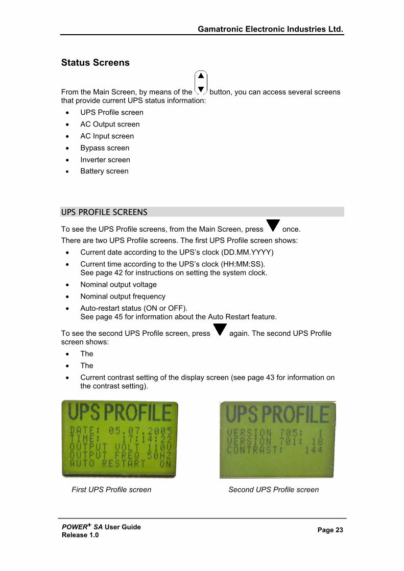
UPS PROFILE SCREENS
To see the UPS Profile screens, from the Main Screen, press once. There are two UPS Profile screens. The first UPS Profile screen shows:
• Current date according to the UPS’s clock (DD.MM.YYYY) • Current time according to the UPS’s clock (HH:MM:SS).
See page 42 for instructions on setting the system clock. • Nominal output voltage • Nominal output frequency • Auto-restart status (ON or OFF).
See page 45 for information about the Auto Restart feature.
To see the second UPS Profile screen, press again. The second UPS Profile screen shows:
• The • The • Current contrast setting of the display screen (see page 43 for information on
the contrast setting).
First UPS Profile screen Second UPS Profile screen
Gamatronic Electronic Industries Ltd.
Page 24 POWER+ SA User GuideRelease 1.0
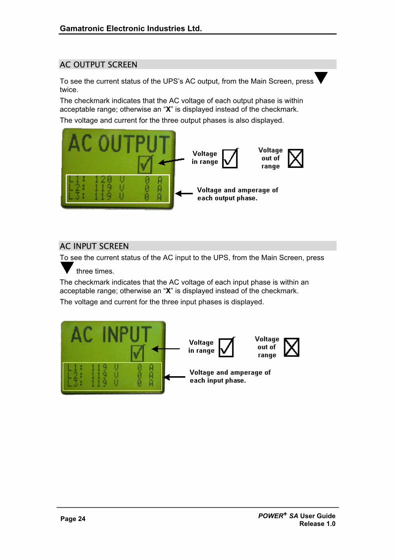
AC OUTPUT SCREEN
To see the current status of the UPS’s AC output, from the Main Screen, press twice. The checkmark indicates that the AC voltage of each output phase is within acceptable range; otherwise an “X” is displayed instead of the checkmark. The voltage and current for the three output phases is also displayed.
AC INPUT SCREEN To see the current status of the AC input to the UPS, from the Main Screen, press
three times. The checkmark indicates that the AC voltage of each input phase is within an acceptable range; otherwise an “X” is displayed instead of the checkmark. The voltage and current for the three input phases is displayed.
Gamatronic Electronic Industries Ltd.
POWER+ SA User Guide Release 1.0
Page 25
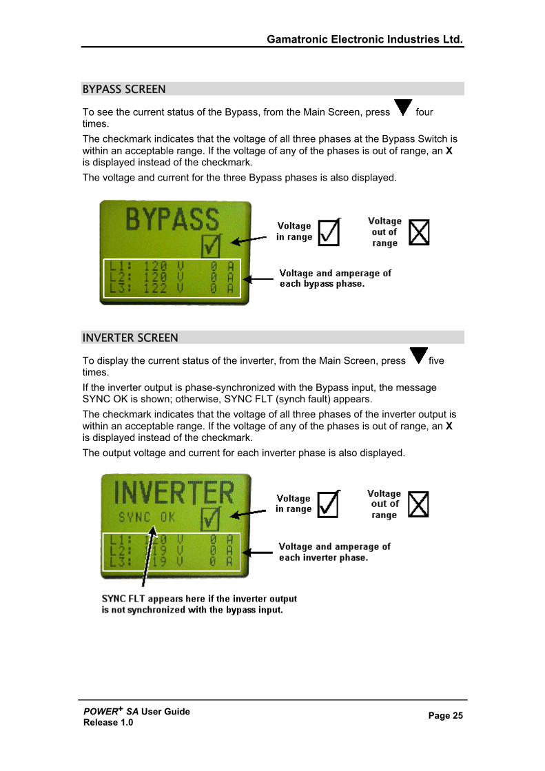
BYPASS SCREEN
To see the current status of the Bypass, from the Main Screen, press four times. The checkmark indicates that the voltage of all three phases at the Bypass Switch is within an acceptable range. If the voltage of any of the phases is out of range, an X is displayed instead of the checkmark. The voltage and current for the three Bypass phases is also displayed.
INVERTER SCREEN
To display the current status of the inverter, from the Main Screen, press five times. If the inverter output is phase-synchronized with the Bypass input, the message SYNC OK is shown; otherwise, SYNC FLT (synch fault) appears. The checkmark indicates that the voltage of all three phases of the inverter output is within an acceptable range. If the voltage of any of the phases is out of range, an X is displayed instead of the checkmark. The output voltage and current for each inverter phase is also displayed.
Gamatronic Electronic Industries Ltd.
Page 26 POWER+ SA User GuideRelease 1.0
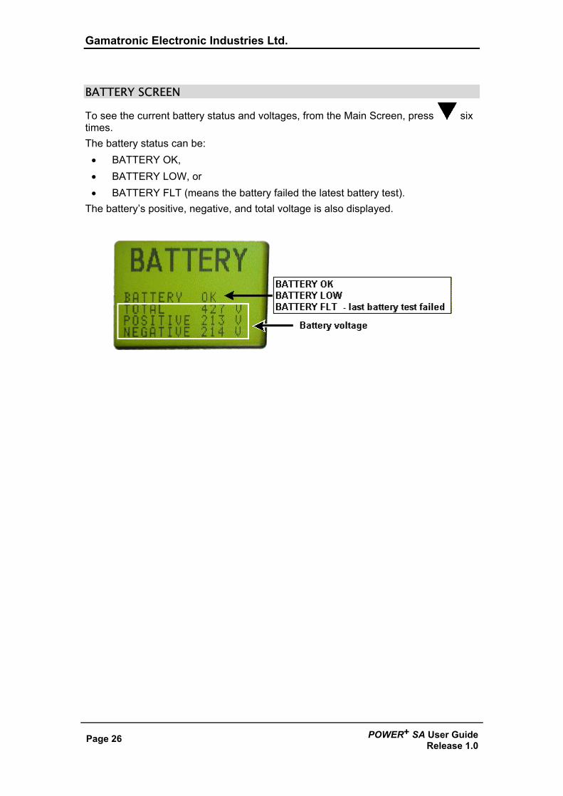
BATTERY SCREEN
To see the current battery status and voltages, from the Main Screen, press six times. The battery status can be:
• BATTERY OK, • BATTERY LOW, or • BATTERY FLT (means the battery failed the latest battery test).
The battery’s positive, negative, and total voltage is also displayed.
Gamatronic Electronic Industries Ltd.
POWER+ SA User Guide Release 1.0
Page 27
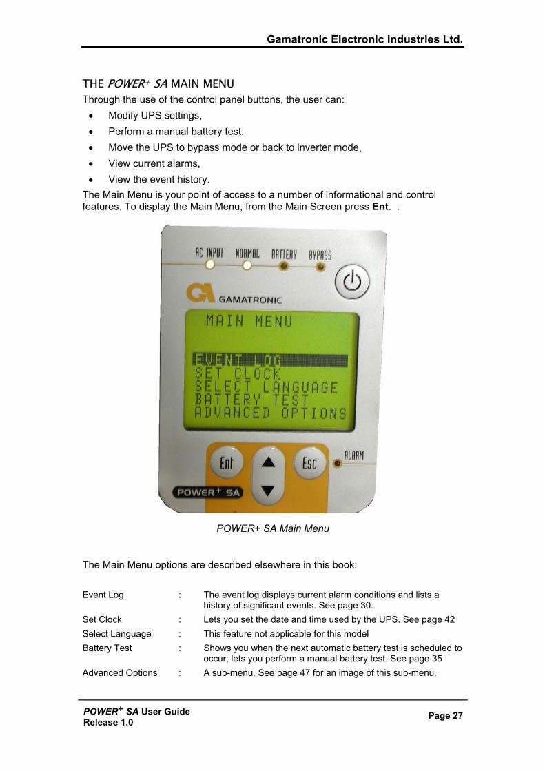
THE POWER+ SA MAIN MENU Through the use of the control panel buttons, the user can:
• Modify UPS settings, • Perform a manual battery test, • Move the UPS to bypass mode or back to inverter mode, • View current alarms, • View the event history.
The Main Menu is your point of access to a number of informational and control features. To display the Main Menu, from the Main Screen press Ent. .
POWER+ SA Main Menu The Main Menu options are described elsewhere in this book: Event Log : The event log displays current alarm conditions and lists a
history of significant events. See page 30. Set Clock : Lets you set the date and time used by the UPS. See page 42 Select Language : This feature not applicable for this model Battery Test : Shows you when the next automatic battery test is scheduled to
occur; lets you perform a manual battery test. See page 35 Advanced Options : A sub-menu. See page 47 for an image of this sub-menu.
Gamatronic Electronic Industries Ltd.
Page 28 POWER+ SA User GuideRelease 1.0
4. DAILY OPERATION
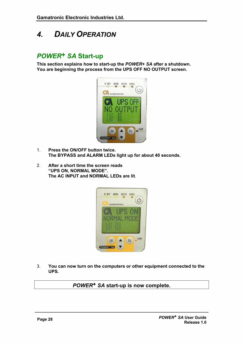
POWER+ SA Start-up This section explains how to start-up the POWER+ SA after a shutdown. You are beginning the process from the UPS OFF NO OUTPUT screen.
1. Press the ON/OFF button twice. The BYPASS and ALARM LEDs light up for about 40 seconds.
2. After a short time the screen reads “UPS ON, NORMAL MODE”. The AC INPUT and NORMAL LEDs are lit.
3. You can now turn on the computers or other equipment connected to the UPS.
POWER+ SA start-up is now complete.
Gamatronic Electronic Industries Ltd.
POWER+ SA User Guide Release 1.0
Page 29
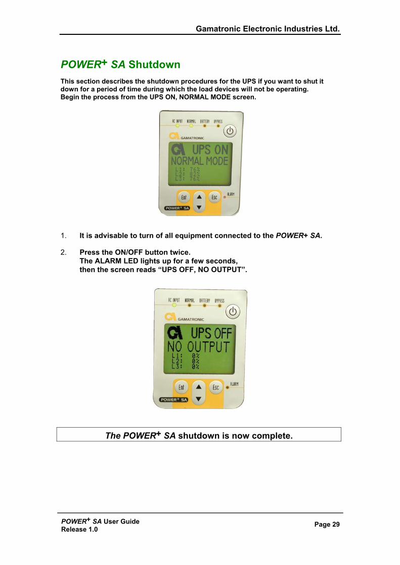
POWER+ SA Shutdown This section describes the shutdown procedures for the UPS if you want to shut it down for a period of time during which the load devices will not be operating. Begin the process from the UPS ON, NORMAL MODE screen.
1. It is advisable to turn of all equipment connected to the POWER+ SA.
2. Press the ON/OFF button twice. The ALARM LED lights up for a few seconds, then the screen reads “UPS OFF, NO OUTPUT”.
The POWER+ SA shutdown is now complete.
Gamatronic Electronic Industries Ltd.
Page 30 POWER+ SA User GuideRelease 1.0
5. THE EVENT LOG The Event Log is really a combination of two functions:
• A display of active alarms • A history of important events that occurred to the UPS.
Alarms In the event of an alarm (the audible alarm sounds or the red alarm light on the POWER+ SA console lights up), go to the Event Log to determine the nature of the problem. (Pressing the Esc key from the Main Screen silences the audible alarm.)
Navigating to the event log To see the event log: 1. From the Main Screen, press the Ent button to display the Main Menu. 2. On the Main Menu, press Ent again.
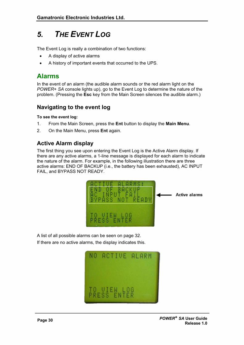
Active Alarm display The first thing you see upon entering the Event Log is the Active Alarm display. If there are any active alarms, a 1-line message is displayed for each alarm to indicate the nature of the alarm. For example, in the following illustration there are three active alarms: END OF BACKUP (i.e., the battery has been exhausted), AC INPUT FAIL, and BYPASS NOT READY.
A list of all possible alarms can be seen on page 32. If there are no active alarms, the display indicates this.
Gamatronic Electronic Industries Ltd.
POWER+ SA User Guide Release 1.0
Page 31
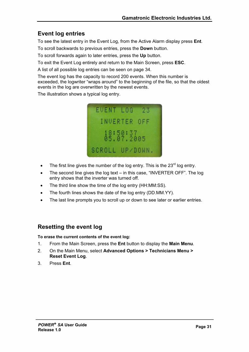
Event log entries To see the latest entry in the Event Log, from the Active Alarm display press Ent. To scroll backwards to previous entries, press the Down button. To scroll forwards again to later entries, press the Up button. To exit the Event Log entirely and return to the Main Screen, press ESC. A list of all possible log entries can be seen on page 34. The event log has the capacity to record 200 events. When this number is exceeded, the logwriter “wraps around” to the beginning of the file, so that the oldest events in the log are overwritten by the newest events. The illustration shows a typical log entry.
• The first line gives the number of the log entry. This is the 23rd log entry. • The second line gives the log text – in this case, “INVERTER OFF”. The log
entry shows that the inverter was turned off. • The third line show the time of the log entry (HH:MM:SS). • The fourth lines shows the date of the log entry (DD.MM.YY). • The last line prompts you to scroll up or down to see later or earlier entries.
Resetting the event log To erase the current contents of the event log: 1. From the Main Screen, press the Ent button to display the Main Menu. 2. On the Main Menu, select Advanced Options > Technicians Menu >
Reset Event Log. 3. Press Ent.
Gamatronic Electronic Industries Ltd.
Page 32 POWER+ SA User GuideRelease 1.0
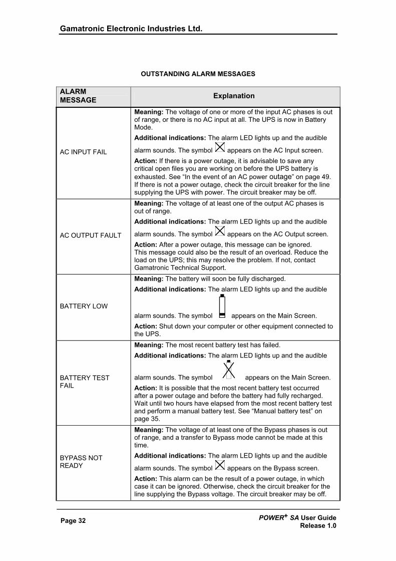
OUTSTANDING ALARM MESSAGES ALARM MESSAGE Explanation
AC INPUT FAIL
Meaning: The voltage of one or more of the input AC phases is out of range, or there is no AC input at all. The UPS is now in Battery Mode. Additional indications: The alarm LED lights up and the audible
alarm sounds. The symbol appears on the AC Input screen. Action: If there is a power outage, it is advisable to save any critical open files you are working on before the UPS battery is exhausted. See “In the event of an AC power outage” on page 49. If there is not a power outage, check the circuit breaker for the line supplying the UPS with power. The circuit breaker may be off.
AC OUTPUT FAULT
Meaning: The voltage of at least one of the output AC phases is out of range. Additional indications: The alarm LED lights up and the audible
alarm sounds. The symbol appears on the AC Output screen. Action: After a power outage, this message can be ignored. This message could also be the result of an overload. Reduce the load on the UPS; this may resolve the problem. If not, contact Gamatronic Technical Support.
BATTERY LOW
Meaning: The battery will soon be fully discharged. Additional indications: The alarm LED lights up and the audible
alarm sounds. The symbol appears on the Main Screen. Action: Shut down your computer or other equipment connected to the UPS.
BATTERY TEST FAIL
Meaning: The most recent battery test has failed. Additional indications: The alarm LED lights up and the audible
alarm sounds. The symbol appears on the Main Screen. Action: It is possible that the most recent battery test occurred after a power outage and before the battery had fully recharged. Wait until two hours have elapsed from the most recent battery test and perform a manual battery test. See “Manual battery test” on page 35.
BYPASS NOT READY
Meaning: The voltage of at least one of the Bypass phases is out of range, and a transfer to Bypass mode cannot be made at this time. Additional indications: The alarm LED lights up and the audible
alarm sounds. The symbol appears on the Bypass screen. Action: This alarm can be the result of a power outage, in which case it can be ignored. Otherwise, check the circuit breaker for the line supplying the Bypass voltage. The circuit breaker may be off.
Gamatronic Electronic Industries Ltd.
POWER+ SA User Guide Release 1.0
Page 33
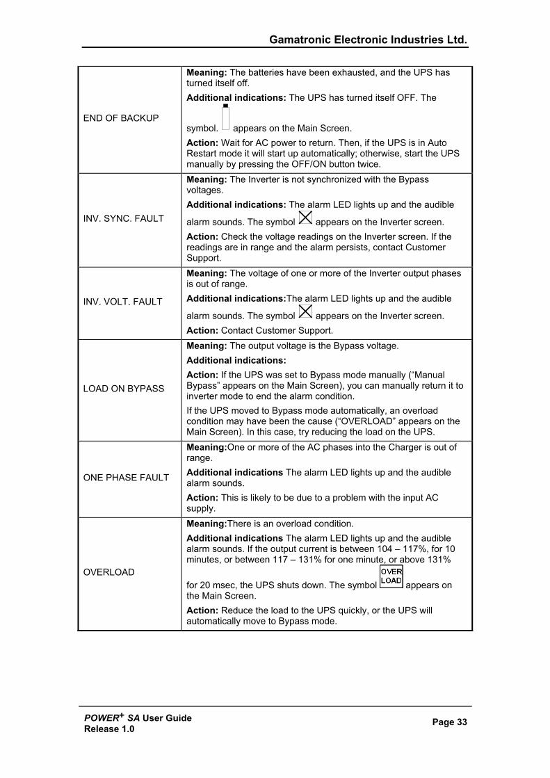
END OF BACKUP
Meaning: The batteries have been exhausted, and the UPS has turned itself off. Additional indications: The UPS has turned itself OFF. The
symbol. appears on the Main Screen. Action: Wait for AC power to return. Then, if the UPS is in Auto Restart mode it will start up automatically; otherwise, start the UPS manually by pressing the OFF/ON button twice.
INV. SYNC. FAULT
Meaning: The Inverter is not synchronized with the Bypass voltages. Additional indications: The alarm LED lights up and the audible
alarm sounds. The symbol appears on the Inverter screen. Action: Check the voltage readings on the Inverter screen. If the readings are in range and the alarm persists, contact Customer Support.
INV. VOLT. FAULT
Meaning: The voltage of one or more of the Inverter output phases is out of range. Additional indications:The alarm LED lights up and the audible
alarm sounds. The symbol appears on the Inverter screen. Action: Contact Customer Support.
LOAD ON BYPASS
Meaning: The output voltage is the Bypass voltage. Additional indications: Action: If the UPS was set to Bypass mode manually (“Manual Bypass” appears on the Main Screen), you can manually return it to inverter mode to end the alarm condition. If the UPS moved to Bypass mode automatically, an overload condition may have been the cause (“OVERLOAD” appears on the Main Screen). In this case, try reducing the load on the UPS.
ONE PHASE FAULT
Meaning:One or more of the AC phases into the Charger is out of range. Additional indications The alarm LED lights up and the audible alarm sounds. Action: This is likely to be due to a problem with the input AC supply.
OVERLOAD
Meaning:There is an overload condition. Additional indications The alarm LED lights up and the audible alarm sounds. If the output current is between 104 – 117%, for 10 minutes, or between 117 – 131% for one minute, or above 131%
for 20 msec, the UPS shuts down. The symbol appears on the Main Screen. Action: Reduce the load to the UPS quickly, or the UPS will automatically move to Bypass mode.
Gamatronic Electronic Industries Ltd.
Page 34 POWER+ SA User GuideRelease 1.0
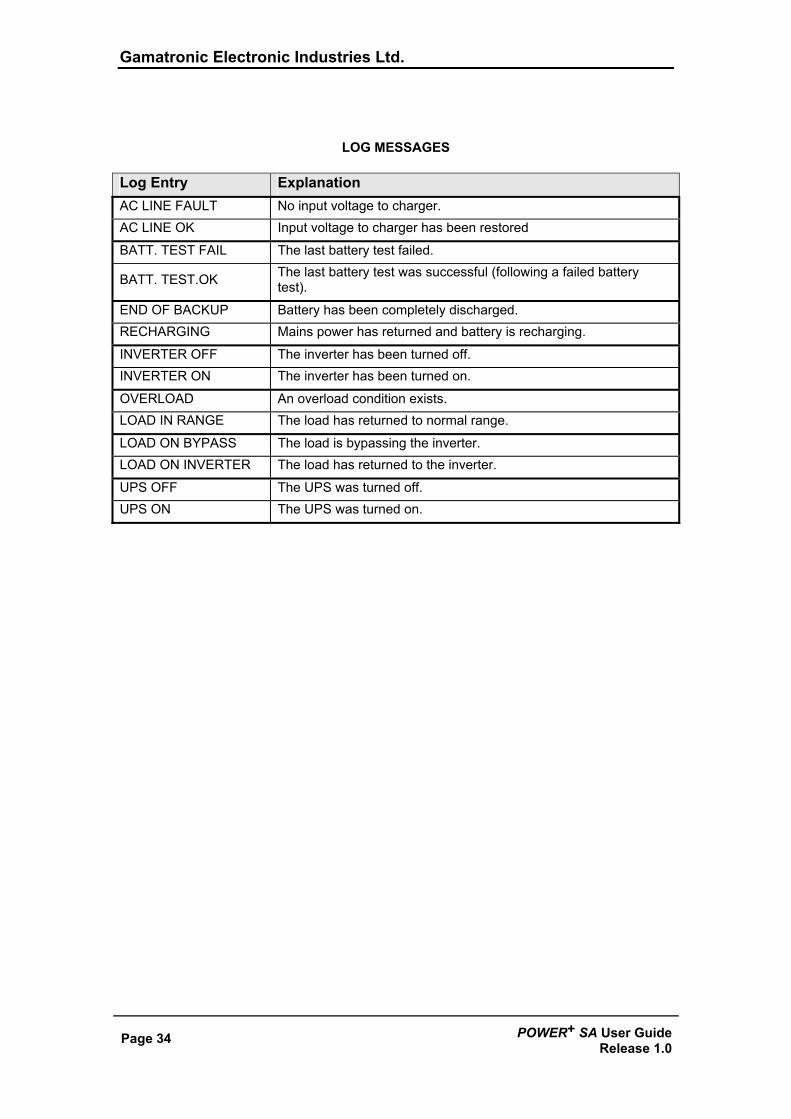
LOG MESSAGES Log Entry Explanation AC LINE FAULT No input voltage to charger. AC LINE OK Input voltage to charger has been restored
BATT. TEST FAIL The last battery test failed.
BATT. TEST.OK The last battery test was successful (following a failed battery test).
END OF BACKUP Battery has been completely discharged. RECHARGING Mains power has returned and battery is recharging.
INVERTER OFF The inverter has been turned off. INVERTER ON The inverter has been turned on.
OVERLOAD An overload condition exists. LOAD IN RANGE The load has returned to normal range.
LOAD ON BYPASS The load is bypassing the inverter. LOAD ON INVERTER The load has returned to the inverter.
UPS OFF The UPS was turned off. UPS ON The UPS was turned on.
Gamatronic Electronic Industries Ltd.
POWER+ SA User Guide Release 1.0
Page 35
6. BATTERY TESTS
Automatic battery test The POWER+ SA is programmed to perform a battery test automatically every two weeks.
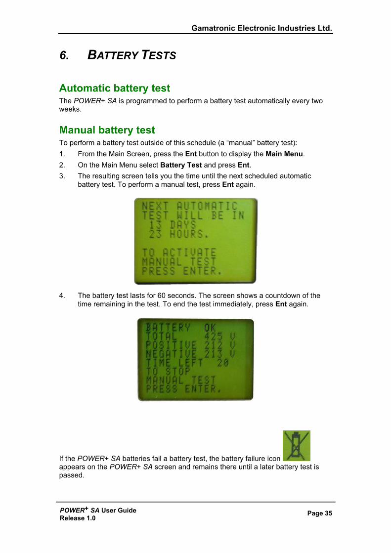
Manual battery test To perform a battery test outside of this schedule (a “manual” battery test): 1. From the Main Screen, press the Ent button to display the Main Menu. 2. On the Main Menu select Battery Test and press Ent. 3. The resulting screen tells you the time until the next scheduled automatic
battery test. To perform a manual test, press Ent again.
4. The battery test lasts for 60 seconds. The screen shows a countdown of the time remaining in the test. To end the test immediately, press Ent again.
If the POWER+ SA batteries fail a battery test, the battery failure icon appears on the POWER+ SA screen and remains there until a later battery test is passed.
Gamatronic Electronic Industries Ltd.
Page 36 POWER+ SA User GuideRelease 1.0
7. FIRST-TIME SETUP
Cable Connections
Only an authorized electrician may wire the UPS power connections. Do not attempt to wire any of the power connections on your own.
To connect the required cables to the UPS: 1. Ensure that the lines coming into the UPS are equipped with circuit breakers of
the following capacity or greater: UPS output: 32A Bypass output: 32A AC input: 25A The following table gives the required cable diameters that must be used when connecting the UPS. The table states the cable diameters in mm2. AC output Neutral wire and Bypass input Neutral wire
AC output Gnd,R,S,T
Bypass input Gnd,R,S,T
AC input Gnd,N,R,S,T Battery input
6 mm2 4 mm2 4 mm2 4 mm2 6 mm2
(Use the battery cable supplied by Gamatronic.)
Gamatronic Electronic Industries Ltd.
POWER+ SA User Guide Release 1.0
Page 37
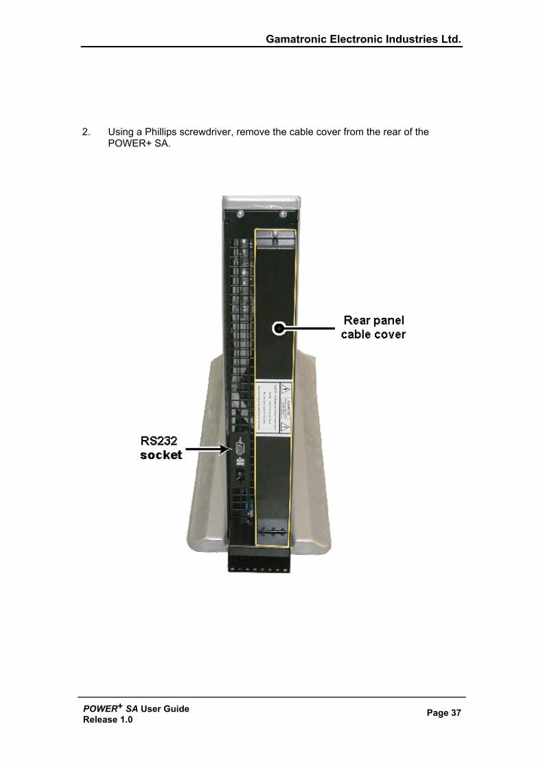
2. Using a Phillips screwdriver, remove the cable cover from the rear of the
POWER+ SA.
Gamatronic Electronic Industries Ltd.
Page 38 POWER+ SA User GuideRelease 1.0
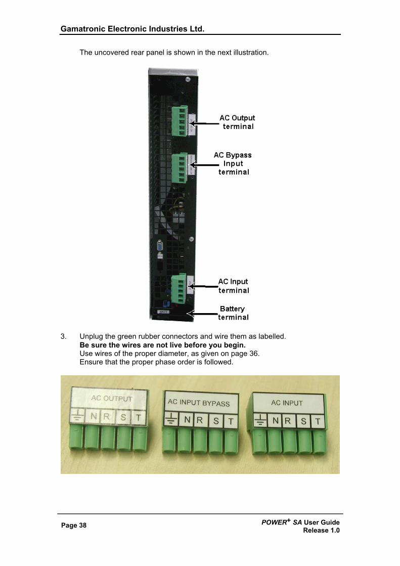
The uncovered rear panel is shown in the next illustration.
3. Unplug the green rubber connectors and wire them as labelled. Be sure the wires are not live before you begin. Use wires of the proper diameter, as given on page 36. Ensure that the proper phase order is followed.
Gamatronic Electronic Industries Ltd.
POWER+ SA User Guide Release 1.0
Page 39
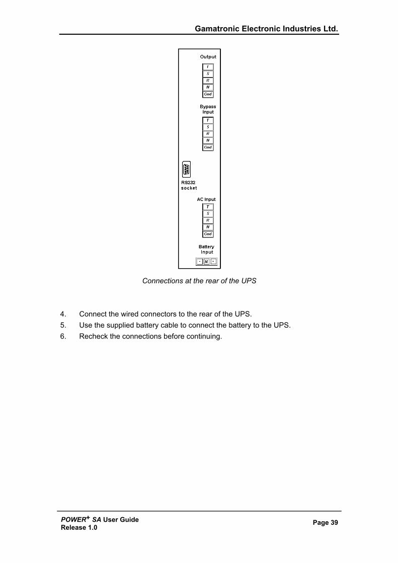
Connections at the rear of the UPS
4. Connect the wired connectors to the rear of the UPS. 5. Use the supplied battery cable to connect the battery to the UPS. 6. Recheck the connections before continuing.
Gamatronic Electronic Industries Ltd.
Page 40 POWER+ SA User GuideRelease 1.0
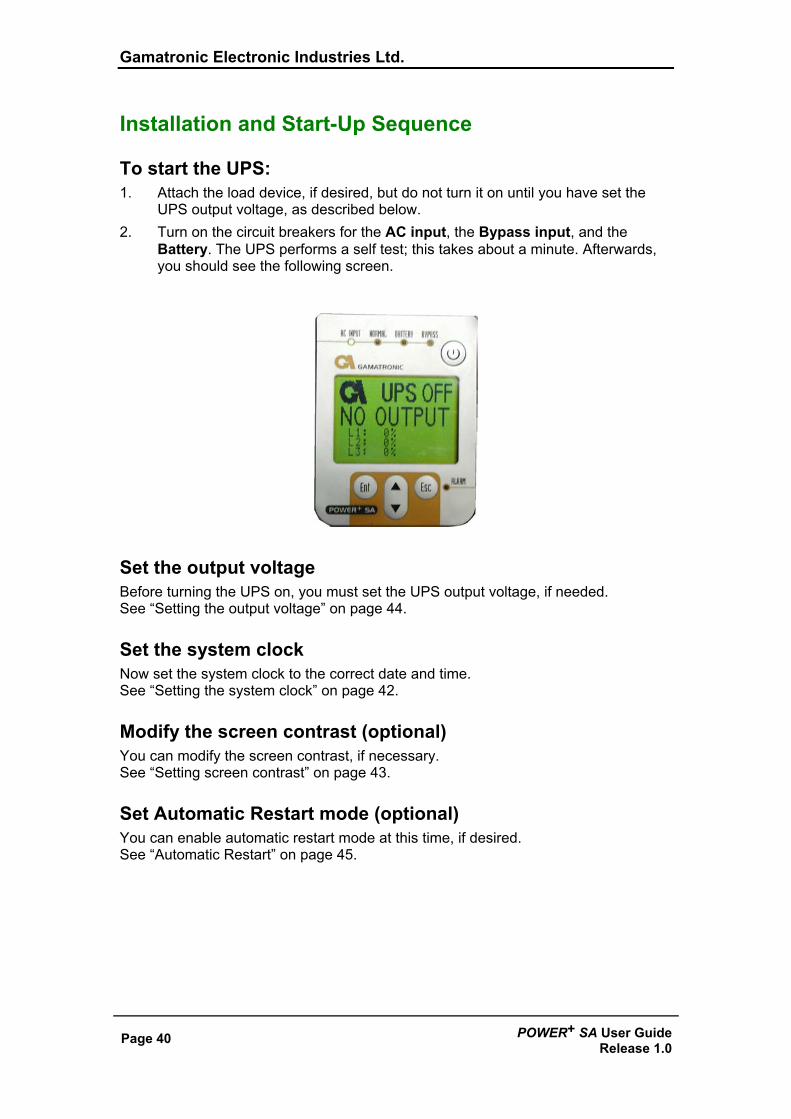
Installation and Start-Up Sequence
To start the UPS: 1. Attach the load device, if desired, but do not turn it on until you have set the
UPS output voltage, as described below. 2. Turn on the circuit breakers for the AC input, the Bypass input, and the
Battery. The UPS performs a self test; this takes about a minute. Afterwards, you should see the following screen.
Set the output voltage Before turning the UPS on, you must set the UPS output voltage, if needed. See “Setting the output voltage” on page 44.
Set the system clock Now set the system clock to the correct date and time. See “Setting the system clock” on page 42.
Modify the screen contrast (optional) You can modify the screen contrast, if necessary. See “Setting screen contrast” on page 43.
Set Automatic Restart mode (optional) You can enable automatic restart mode at this time, if desired. See “Automatic Restart” on page 45.
Gamatronic Electronic Industries Ltd.
POWER+ SA User Guide Release 1.0
Page 41
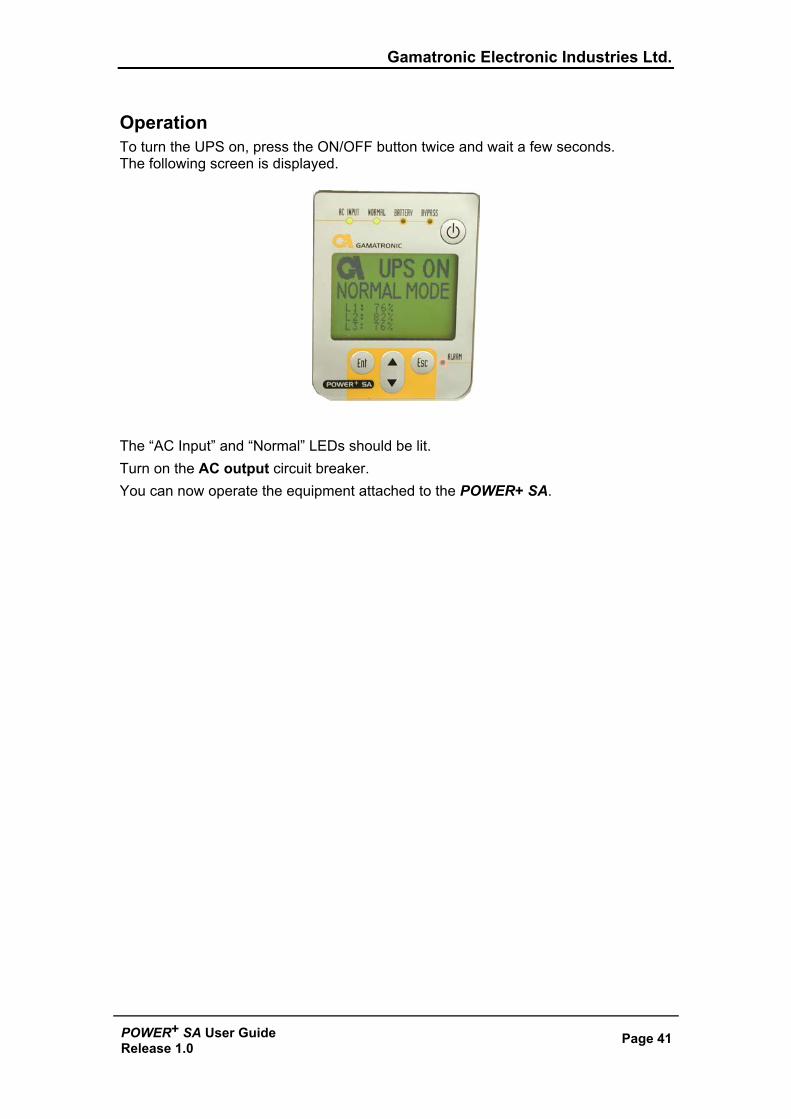
Operation To turn the UPS on, press the ON/OFF button twice and wait a few seconds. The following screen is displayed.
The “AC Input” and “Normal” LEDs should be lit. Turn on the AC output circuit breaker. You can now operate the equipment attached to the POWER+ SA.
Gamatronic Electronic Industries Ltd.
Page 42 POWER+ SA User GuideRelease 1.0
8. SETTING SYSTEM PARAMETERS There are several system parameters that can be modified as needed. In general, you only need set these parameters once, during the first-time setup of the POWER+ SA.
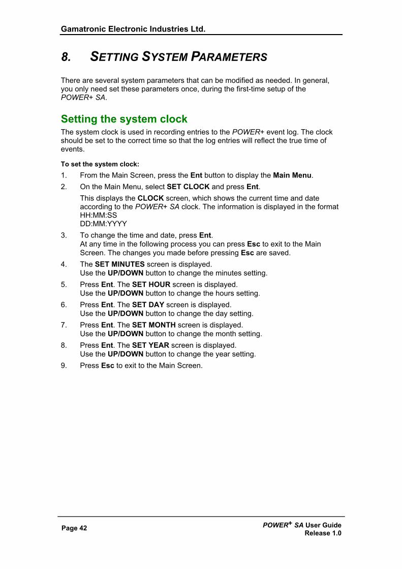
Setting the system clock The system clock is used in recording entries to the POWER+ event log. The clock should be set to the correct time so that the log entries will reflect the true time of events.
To set the system clock: 1. From the Main Screen, press the Ent button to display the Main Menu. 2. On the Main Menu, select SET CLOCK and press Ent.
This displays the CLOCK screen, which shows the current time and date according to the POWER+ SA clock. The information is displayed in the format HH:MM:SS DD:MM:YYYY
3. To change the time and date, press Ent. At any time in the following process you can press Esc to exit to the Main Screen. The changes you made before pressing Esc are saved.
4. The SET MINUTES screen is displayed. Use the UP/DOWN button to change the minutes setting.
5. Press Ent. The SET HOUR screen is displayed. Use the UP/DOWN button to change the hours setting.
6. Press Ent. The SET DAY screen is displayed. Use the UP/DOWN button to change the day setting.
7. Press Ent. The SET MONTH screen is displayed. Use the UP/DOWN button to change the month setting.
8. Press Ent. The SET YEAR screen is displayed. Use the UP/DOWN button to change the year setting.
9. Press Esc to exit to the Main Screen.
Gamatronic Electronic Industries Ltd.
POWER+ SA User Guide Release 1.0
Page 43
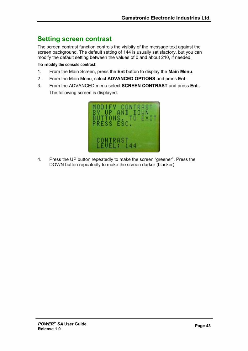
Setting screen contrast The screen contrast function controls the visibity of the message text against the screen background. The default setting of 144 is usually satisfactory, but you can modify the default setting between the values of 0 and about 210, if needed. To modify the console contrast: 1. From the Main Screen, press the Ent button to display the Main Menu. 2. From the Main Menu, select ADVANCED OPTIONS and press Ent. 3. From the ADVANCED menu select SCREEN CONTRAST and press Ent..
The following screen is displayed.
4. Press the UP button repeatedly to make the screen “greener”. Press the DOWN button repeatedly to make the screen darker (blacker).
Gamatronic Electronic Industries Ltd.
Page 44 POWER+ SA User GuideRelease 1.0
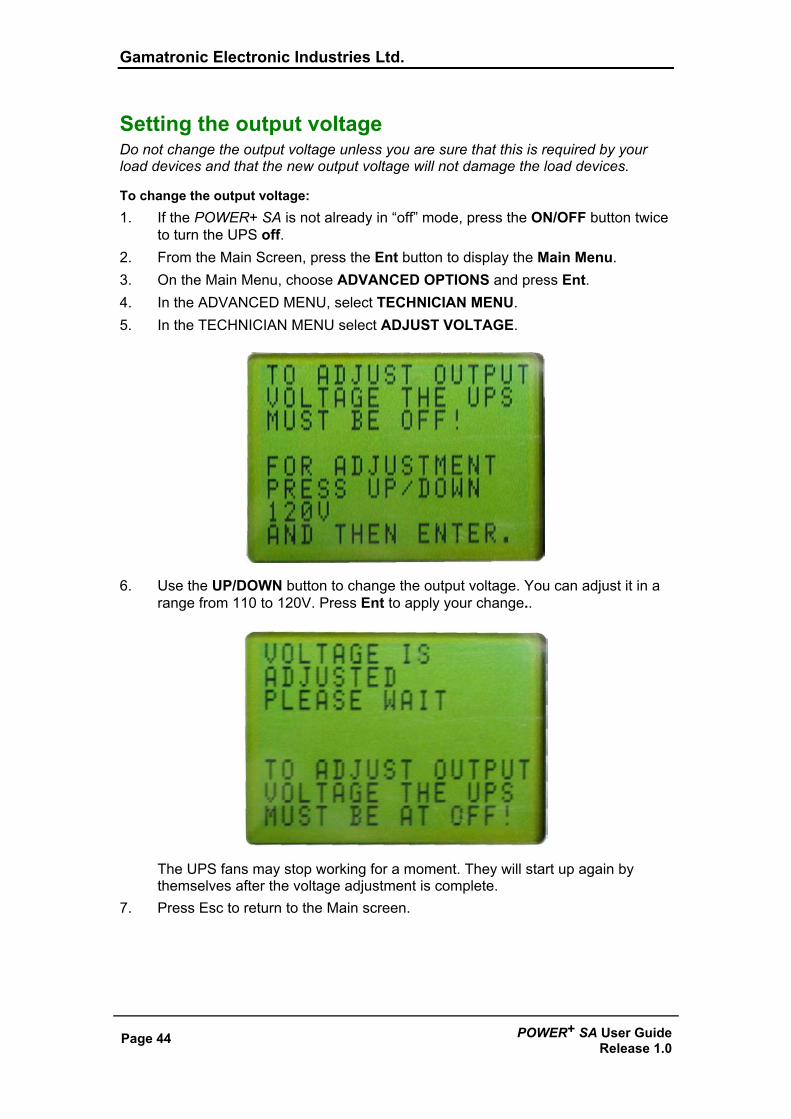
Setting the output voltage
Do not change the output voltage unless you are sure that this is required by your load devices and that the new output voltage will not damage the load devices.
To change the output voltage: 1. If the POWER+ SA is not already in “off” mode, press the ON/OFF button twice
to turn the UPS off. 2. From the Main Screen, press the Ent button to display the Main Menu. 3. On the Main Menu, choose ADVANCED OPTIONS and press Ent. 4. In the ADVANCED MENU, select TECHNICIAN MENU. 5. In the TECHNICIAN MENU select ADJUST VOLTAGE.
6. Use the UP/DOWN button to change the output voltage. You can adjust it in a range from 110 to 120V. Press Ent to apply your change..
The UPS fans may stop working for a moment. They will start up again by themselves after the voltage adjustment is complete.
7. Press Esc to return to the Main screen.
Gamatronic Electronic Industries Ltd.
POWER+ SA User Guide Release 1.0
Page 45
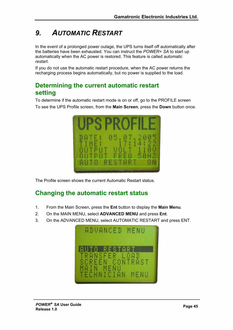
9. AUTOMATIC RESTART In the event of a prolonged power outage, the UPS turns itself off automatically after the batteries have been exhausted. You can instruct the POWER+ SA to start up automatically when the AC power is restored. This feature is called automatic restart. If you do not use the automatic restart procedure, when the AC power returns the recharging process begins automatically, but no power is supplied to the load.
Determining the current automatic restart setting To determine if the automatic restart mode is on or off, go to the PROFILE screen To see the UPS Profile screen, from the Main Screen, press the Down button once.
The Profile screen shows the current Automatic Restart status.
Changing the automatic restart status 1. From the Main Screen, press the Ent button to display the Main Menu. 2. On the MAIN MENU, select ADVANCED MENU and press Ent. 3. On the ADVANCED MENU, select AUTOMATIC RESTART and press ENT.

Gamatronic Electronic Industries Ltd.
Page 46 POWER+ SA User GuideRelease 1.0
4. Press Ent to change the automatic restart status.
5. The new automatic restart status is displayed. Press Esc to return to the Main Screen.
Gamatronic Electronic Industries Ltd.
POWER+ SA User Guide Release 1.0
Page 47
10. MISCELLANEOUS FUNCTIONS This section describes infrequently used but important features.
Manually entering or leaving Bypass Mode When the AC input power is normal, it is handled by the UPS in one of two ways:
• The input AC power is sent to the inverter, where it is regulated and passed on to the load. This is called Normal Mode or Inverter Mode.
• The input AC power bypasses the inverter entirely and goes directly to the load with no regulation. This is called Bypass Mode.
Usually only a technician will need to manually switch the UPS to Bypass mode.
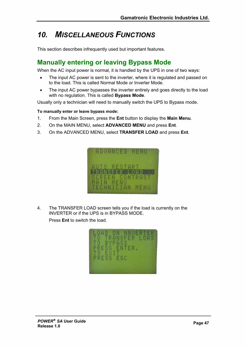
To manually enter or leave bypass mode: 1. From the Main Screen, press the Ent button to display the Main Menu. 2. On the MAIN MENU, select ADVANCED MENU and press Ent. 3. On the ADVANCED MENU, select TRANSFER LOAD and press Ent.
4. The TRANSFER LOAD screen tells you if the load is currently on the
INVERTER or if the UPS is in BYPASS MODE. Press Ent to switch the load.
Gamatronic Electronic Industries Ltd.
Page 48 POWER+ SA User GuideRelease 1.0
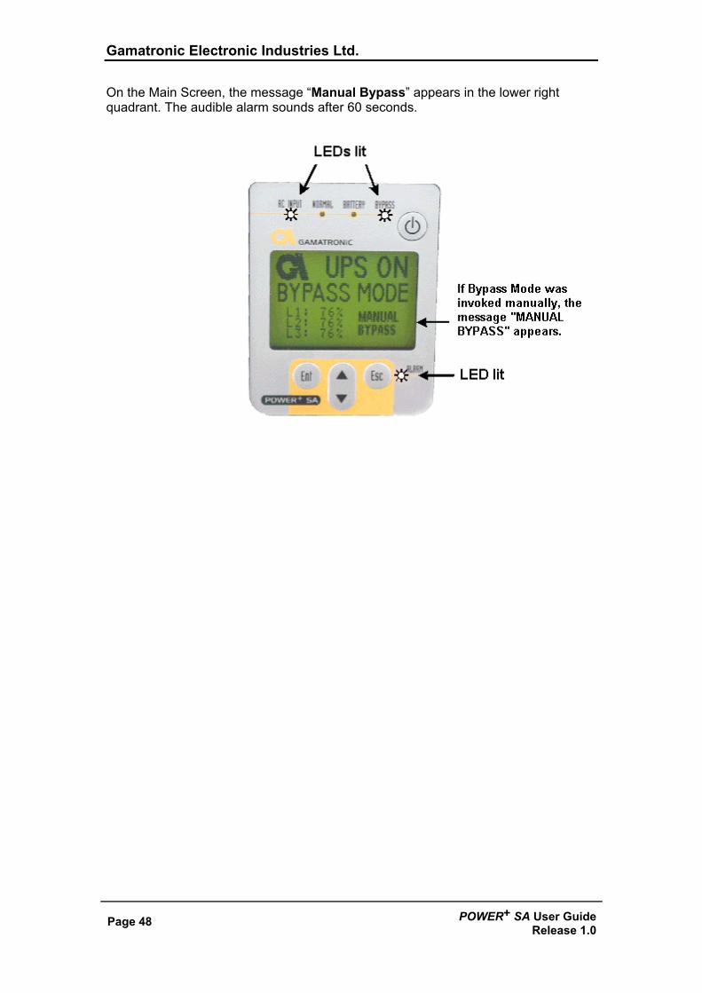
On the Main Screen, the message “Manual Bypass” appears in the lower right quadrant. The audible alarm sounds after 60 seconds.
Gamatronic Electronic Industries Ltd.
POWER+ SA User Guide Release 1.0
Page 49
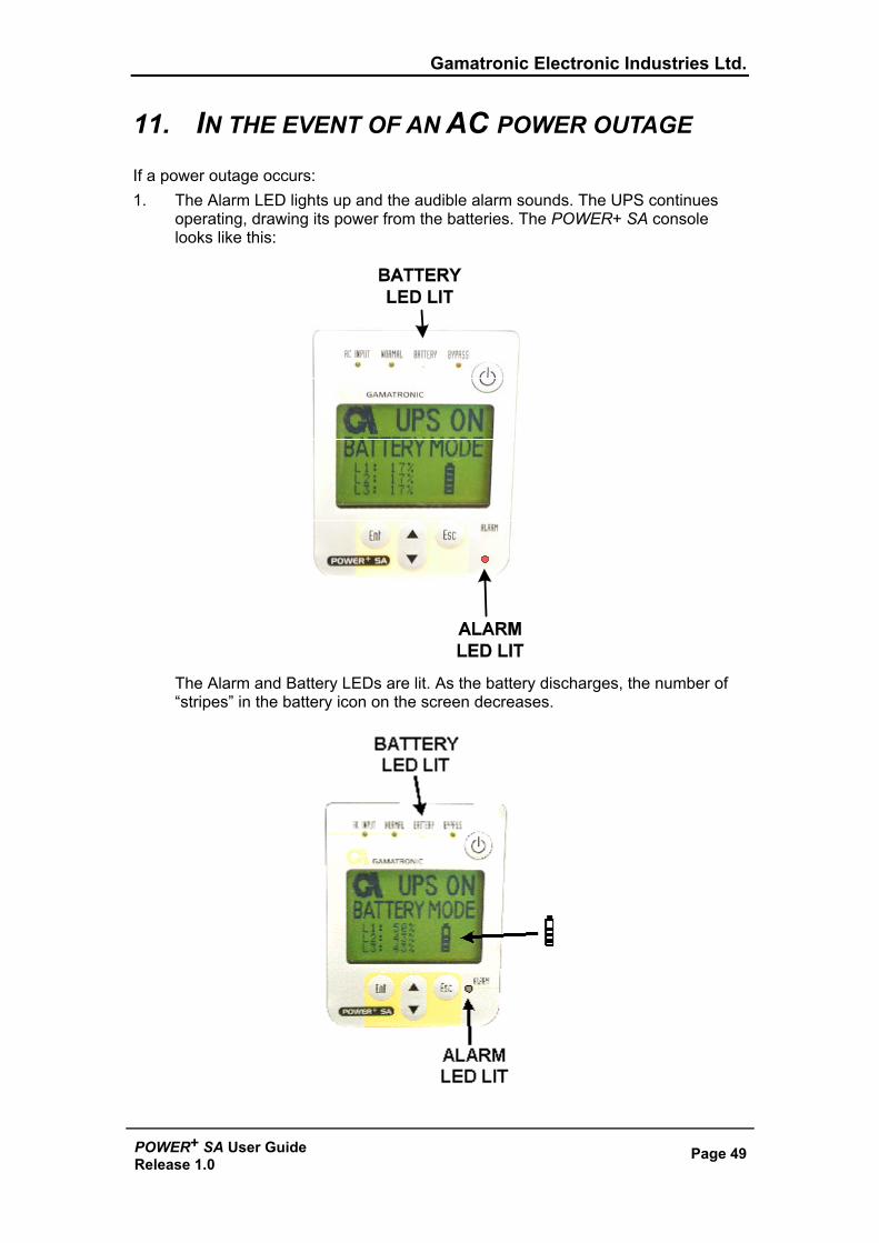
11. IN THE EVENT OF AN AC POWER OUTAGE If a power outage occurs: 1. The Alarm LED lights up and the audible alarm sounds. The UPS continues
operating, drawing its power from the batteries. The POWER+ SA console looks like this:
The Alarm and Battery LEDs are lit. As the battery discharges, the number of “stripes” in the battery icon on the screen decreases.
Gamatronic Electronic Industries Ltd.
Page 50 POWER+ SA User GuideRelease 1.0
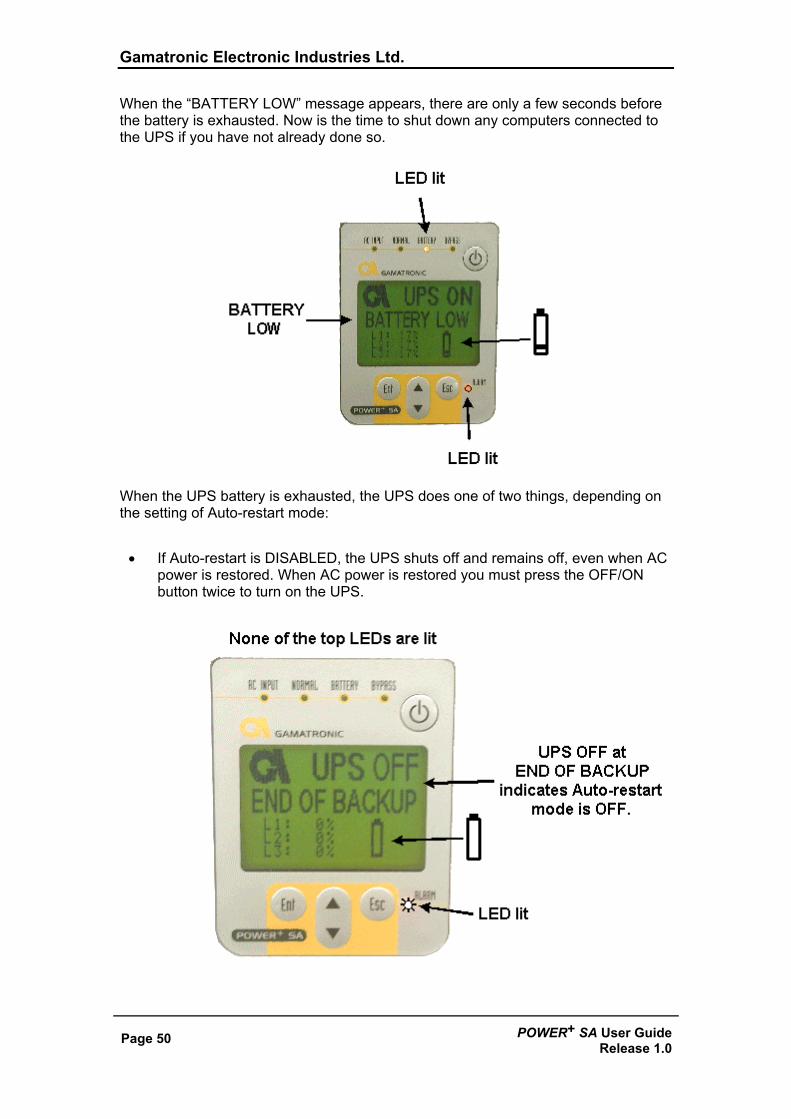
When the “BATTERY LOW” message appears, there are only a few seconds before the battery is exhausted. Now is the time to shut down any computers connected to the UPS if you have not already done so.
When the UPS battery is exhausted, the UPS does one of two things, depending on the setting of Auto-restart mode:
• If Auto-restart is DISABLED, the UPS shuts off and remains off, even when AC power is restored. When AC power is restored you must press the OFF/ON button twice to turn on the UPS.
Gamatronic Electronic Industries Ltd.
POWER+ SA User Guide Release 1.0
Page 51
• If Auto-restart is ENABLED, the Main Screen shows the UPS ON message. When AC power is restored, the UPS starts up automatically.
Gamatronic Electronic Industries Ltd.
Page 52 POWER+ SA User GuideRelease 1.0
12. TROUBLESHOOTING This section explains what to do in the event of an alarm condition, or when any other “out of the ordinary” event occurs on the UPS.
Alarm sounds and/or Alarm LED lights up 1. Go to the Event Log and look at the Active Alarm Display to determine the
nature of the alarm. See “Navigating to the event log” and “Active Alarm display” on page 30.
2. Look for the appropriate heading below according to the nature of the alarm, and follow the instructions.
Electricity returned but UPS remains in Battery Mode Check the external circuit breaker for the AC line. The circuit breaker may be off.
Battery Test failed It may be that an automatically scheduled battery test was executed shortly after the end of a power outage, when the battery was still charging. Wait until about two hours after the return of the AC power and perform a manual battery test. This should clear the alarm.
The UPS remains in Bypass mode The UPS may have been put in Bypass mode manually. In such a case, the lower left quadrant of the Main Screen says “Manual Bypass”. To manually return the UPS to Normal mode, see “Manually entering or leaving Bypass Mode” on page 47
Sync Fault Verify that the AC Input and the Bypass Input lines are connected to the UPS in proper phase sequence. Verify that AC of the proper frequency (Hz) is being used. (See on page 58.)
Gamatronic Electronic Industries Ltd.
POWER+ SA User Guide Release 1.0
Page 53
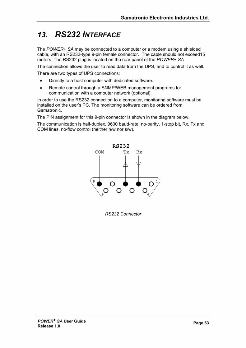
13. RS232 INTERFACE The POWER+ SA may be connected to a computer or a modem using a shielded cable, with an RS232-type 9-pin female connector. The cable should not exceed15 meters. The RS232 plug is located on the rear panel of the POWER+ SA. The connection allows the user to read data from the UPS, and to control it as well. There are two types of UPS connections:
• Directly to a host computer with dedicated software. • Remote control through a SNMP/WEB management programs for
communication with a computer network (optional). In order to use the RS232 connection to a computer, monitoring software must be installed on the user’s PC. The monitoring software can be ordered from Gamatronic. The PIN assignment for this 9-pin connector is shown in the diagram below. The communication is half-duplex, 9600 baud-rate, no-parity, 1-stop bit, Rx, Tx and COM lines, no-flow control (neither h/w nor s/w).
RS232 Connector
15
69
RxTxCOMRS232
Gamatronic Electronic Industries Ltd.
Page 54 POWER+ SA User GuideRelease 1.0
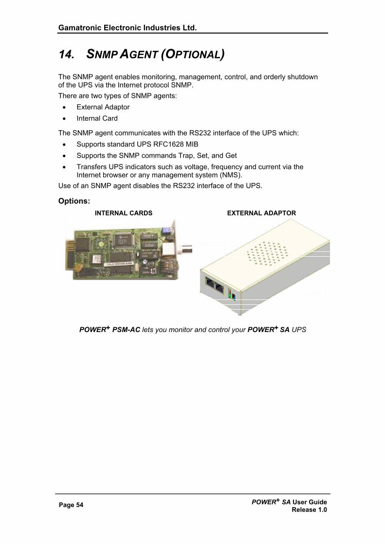
14. SNMP AGENT (OPTIONAL) The SNMP agent enables monitoring, management, control, and orderly shutdown of the UPS via the Internet protocol SNMP. There are two types of SNMP agents:
• External Adaptor • Internal Card
The SNMP agent communicates with the RS232 interface of the UPS which: • Supports standard UPS RFC1628 MIB • Supports the SNMP commands Trap, Set, and Get • Transfers UPS indicators such as voltage, frequency and current via the
Internet browser or any management system (NMS). Use of an SNMP agent disables the RS232 interface of the UPS.
Options: INTERNAL CARDS EXTERNAL ADAPTOR
POWER+ PSM-AC lets you monitor and control your POWER+ SA UPS
Gamatronic Electronic Industries Ltd.
POWER+ SA User Guide Release 1.0
Page 55
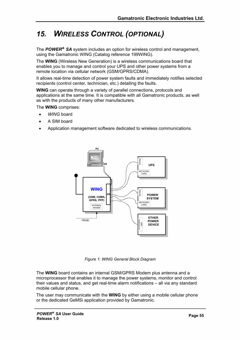
15. WIRELESS CONTROL (OPTIONAL)
The POWER+ SA system includes an option for wireless control and management, using the Gamatronic WING (Catalog reference 199WING). The WING (Wireless New Generation) is a wireless communications board that enables you to manage and control your UPS and other power systems from a remote location via cellular network (GSM/GPRS/CDMA). It allows real-time detection of power system faults and immediately notifies selected recipients (control center, technician, etc.) detailing the faults. WING can operate through a variety of parallel connections, protocols and applications at the same time. It is compatible with all Gamatronic products, as well as with the products of many other manufacturers. The WING comprises:
• WING board • A SIM board • Application management software dedicated to wireless communications.
WING(GSM, CDMA,GPRS, PPP)
D9
UPS
NETWORKCARD
NETWORKCARD
POWERSYSTEM
RS
232R
S232
INTERNALMODEM
+9vdc
PC
D9
OTHERPOWER DEVICE
DR
YC
ON
TAC
TS
Figure 1: WING General Block Diagram
The WING board contains an internal GSM/GPRS Modem plus antenna and a microprocessor that enables it to manage the power systems, monitor and control their values and status, and get real-time alarm notifications – all via any standard mobile cellular phone. The user may communicate with the WING by either using a mobile cellular phone or the dedicated GeMSi application provided by Gamatronic.
Gamatronic Electronic Industries Ltd.
Page 56 POWER+ SA User GuideRelease 1.0
A service technician can perform the following activities using his mobile phone: • Specify the code or command appropriate to the specific needs • Send a message via SMS to the system ID
The system replies, informing the sender whether the command was performed. The board can filter the received messages by authorizations (complete management/monitoring only/none). The WING scans the remote power system every three seconds and alerts all the predefined recipients. (up to 10 recipients) whenever a malfunction occurs. The WING enables you to protect your system by 2 levels of passwords (administrator, technician) and broadcast a message in the case of an alarm.
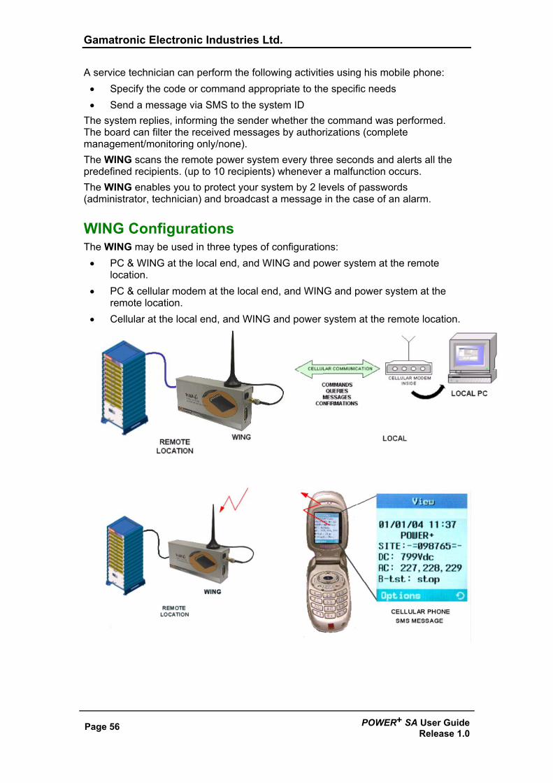
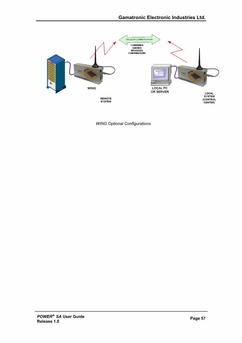
WING Configurations The WING may be used in three types of configurations:
• PC & WING at the local end, and WING and power system at the remote location.
• PC & cellular modem at the local end, and WING and power system at the remote location.
• Cellular at the local end, and WING and power system at the remote location.
Gamatronic Electronic Industries Ltd.
POWER+ SA User Guide Release 1.0
Page 57
WING Optional Configurations
Gamatronic Electronic Industries Ltd.
Page 58 POWER+ SA User GuideRelease 1.0
This page deliberately left blank.
Gamatronic Electronic Industries Ltd.
POWER + SA User Guide Release 1.0
Page 59
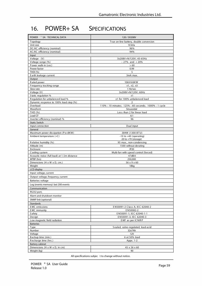
16. POWER+ SA SPECIFICATIONS POWER + SA TECHNICAL DATA 120 / 3X208V
noisrevnoc elbuod ,yrettab enil-no eurT ygolopoTUnit size 10 kVa
%69 )lanimon( ycneiciffe CA/CD %49 )lanimon( ycneiciffe CA/CA
Input zH56-54 ;V021/N+V802x3 )V( egatloV
%02 + dna %72 – )%( egnar egatloV 06 > )ces( ni-klaw rewoP
Power factor 0.99 THDI (%) 5
.xam Am3 tnerruc egakael htraEOutput
WK6/AVk10 rewop detaR 3± ,2± ,1± egnar gnikcart ycneuqerF
Slew rate 1 Hz/sec zH06 ;V021/N+V802x3 )V( egatloV
1± % noitaluger citatS daol decnalabnu %001 rof 1± % daol decnalabnu rof noitalugeR
2 )%( pets daol %001 ot esnopser cimanyD elcyc 1 : %0001 ;sdnoces 06 : %521 ;setunim 01 : %011 daolrevO
Waveform Sinusoidal daol raenil rof 2 naht sseL )%( DHT
Load CF 6:1 69 % )lanimon( ycneiciffe retrevnI
Static Switch tupni lauD noitcennoc tupnI
General )UTB 0031( W483 )WK8=oP( noitapissid rewop mumixaM
)gnitarepo( 04+ ot 01- )C÷( erutarepmet tneibmA-20 to +70 (storage)
gnisnednoc-non ,.xam 59 )%( ytidimuh evitaleR gnitared tuohtiw 0051 )m( edutitlA
Enclosure IP20 )decrof( lortnoc deeps htiw naf-itluM metsys gnilooC
ABd74 ecnatsid m5.1 ta )daol lluf( esion citsuocAMTBF (hrs) 250,000
06 x 9 x 65 ).mc ,D x W x H( snoisnemiDWeight 18kg LCD display Input: voltage, current
Output: voltage, frequency, current
Batteries: voltage
Log (events memory): last 200 events
Communication RS232 port,
Alarm and shutdown monitor
SNMP link (optional)
Standards 2-04026 CEI ;A ssalC 2-19005NE snoissime CME
2-28005NE ytinummi CME 1-1-04026 CEI ;1-19005NE ytefaS
3-04026 CEI ;3-19005NE ngiseD PRINCI rep sa FME noitaidar dleif citengam woL
Batteries dica-dael ,detaluger-evlav ,delaeS epyT
Number 32x7Ah Voltage 12V
daol %05 ta 6 ).nim( emit pukcaB 2-1 .xppA ).srh( emit egrahceR
Battery cabinet 06 x 62 x 54 )mc ni ,D x W x H( snoisnemiD
Weight (kg) 90
All speci�cations subjec t to change without notice.
Gamatronic Electronic Industries Ltd.
Page 60 POWER+ SA User GuideRelease 1.0
For a full company profile, please visit out website at www.gamatronic.com.
Gamatronic Building, Jerusalem, Israel
Gamatronic’s product range: UPS Systems
Power systems for Telecom
DC-to-AC Inverters
DC-to-DC Converters
Frequency Changers
Battery Chargers
Power Management Solutions
Headquarters and Factory 14 Hartom Street, Science-Based Industries Park, POB 45029, Jerusalem 97774, Israel Tel-Aviv Sales Office 34 Habarzel Street, Ramat Hachayal, Tel-Aviv Tel: +972-3-6499940 Fax +972-3-6449791 Gamatronic (UK) Ltd. Gamatronic House, Stephenson Court, Priory Business Park, Bedford MK44 3US, United Kingdom Tel: +44 (0)1234 831111 Fax: +44 (0)1234 831114 email: [email protected] Gamatronic Singapore Sales Office email: [email protected]